
On-orbit Experiment Plan of Loop Heat Pipe and the Test ...
12
48th International Conference on Environmental Systems ICES-2018-327 8-12 July 2018, Albuquerque, New Mexico Copyright © 2018 JAXA Figure 1. Schematic of LHP. On-orbit Experiment Plan of Loop Heat Pipe and the Test Results of Thermal Vacuum Test Atsushi Okamoto 1 , Takeshi Miyakita 2 Japan Aerospace Exploration Agency (JAXA), Tsukuba, Ibaraki, 305-8505, Japan Koki Sato 3 and Hosei Nagano 4 Nagoya University, Nagoya, Aichi, 464-8603, Japan It is becoming increasingly difficult to meet the challenging thermal control requirements of modern spacecraft missions with only existing thermal control devices such as conventional heat pipes. A loop heat pipe (LHP) is an effective method to overcome some of these thermal control constraints. The LHP is a passive two-phase heat transfer device that utilizes the evaporation and condensation of a working fluid to transfer heat and capillary force to circulate the fluid. The LHP can transport much heat for a long distance against gravity and has many other excellent characteristics, such as high controllability of operating temperature and a shutdown function. In this study, LHPs for space application have been developing. As a part of the study, bread board model (BBM) of LHP was designed and fabricated. As a result of on-ground test of BBM, it was confirmed that BBM fulfilled all requirement (e.g. maximum transport rate, minimum required heat load for start-up, operating temperature control and shutdown function). To adopt the LHP as a heat transfer device in practical spacecraft mission, the thermal characteristics under the micro- gravity condition should be examined in advance. On-orbit experiment of a LHP radiator system is planned. This paper describes the test plan of on-orbit experiment of a LHP radiator system on International Space Station (ISS) and the results of thermal vacuum test of flight model for on-orbit experiment on ground. I. Introduction T has recently become difficult to meet the increasing thermal control requirement of spacecraft with only existing thermal control devices. A loop heat pipe (LHP) is an effective method to satisfy the requirement. An LHP is a two-phase heat transfer device that utilizes the evaporation and condensation of a working fluid to transfer heat and capillary force to circulate the fluid. 1-3 Figure 1 shows a schematic of an LHP. It consists of an evaporator, a vapor transport line, a condenser, a liquid transport line, and a reservoir (also called a compensation chamber or a hydro-accumulator). The evaporator contains a porous wick that develops a capillary force to circulate the fluid. The operating principle of the LHP is as follows: As heat load is applied to the evaporator, the working fluid is vaporized and a meniscus is formed at the vapor/liquid interface in the evaporator wick. The meniscus develops capillary force and the capillary force circulates the working fluid. The vapor enters the condenser through the vapor line and condenses in the condenser by dissipating the heat to the heat sink. The liquid is subcooled and goes back to the evaporator through the liquid line and bayonet tube. 1 Associate Senior Engineer, Research and Development Directorate, 2-1-1 Sengen, Tsukuba 2 Engineer, Research and Development Directorate, 2-1-1 Sengen, Tsukuba 3 Student, Department of Aerospace Engineering, Furo-cho, Chikusa-ku, Nagoya 4 Professor, Department of Mechanical Engineering, Furo-cho, Chikusa-ku, Nagoya I
Transcript of On-orbit Experiment Plan of Loop Heat Pipe and the Test ...

48th International Conference on Environmental Systems ICES-2018-327 8-12 July 2018, Albuquerque, New Mexico
Copyright © 2018 JAXA
Figure 1. Schematic of LHP.
On-orbit Experiment Plan of Loop Heat Pipe and the Test Results of Thermal Vacuum Test
Atsushi Okamoto1, Takeshi Miyakita2 Japan Aerospace Exploration Agency (JAXA), Tsukuba, Ibaraki, 305-8505, Japan
Koki Sato3 and Hosei Nagano4 Nagoya University, Nagoya, Aichi, 464-8603, Japan
It is becoming increasingly difficult to meet the challenging thermal control requirements of modern spacecraft missions with only existing thermal control devices such as conventional heat pipes. A loop heat pipe (LHP) is an effective method to overcome some of these thermal control constraints. The LHP is a passive two-phase heat transfer device that utilizes the evaporation and condensation of a working fluid to transfer heat and capillary force to circulate the fluid. The LHP can transport much heat for a long distance against gravity and has many other excellent characteristics, such as high controllability of operating temperature and a shutdown function. In this study, LHPs for space application have been developing. As a part of the study, bread board model (BBM) of LHP was designed and fabricated. As a result of on-ground test of BBM, it was confirmed that BBM fulfilled all requirement (e.g. maximum transport rate, minimum required heat load for start-up, operating temperature control and shutdown function). To adopt the LHP as a heat transfer device in practical spacecraft mission, the thermal characteristics under the micro-gravity condition should be examined in advance. On-orbit experiment of a LHP radiator system is planned. This paper describes the test plan of on-orbit experiment of a LHP radiator system on International Space Station (ISS) and the results of thermal vacuum test of flight model for on-orbit experiment on ground.
I. Introduction T has recently become difficult to meet the increasing thermal control requirement of spacecraft with only existing thermal control devices. A loop heat pipe (LHP) is an effective method to satisfy the requirement. An
LHP is a two-phase heat transfer device that utilizes the evaporation and condensation of a working fluid to transfer heat and capillary force to circulate the fluid.1-3 Figure 1 shows a schematic of an LHP. It consists of an evaporator, a vapor transport line, a condenser, a liquid transport line, and a reservoir (also called a compensation chamber or a hydro-accumulator). The evaporator contains a porous wick that develops a capillary force to circulate the fluid. The operating principle of the LHP is as follows: As heat load is applied to the evaporator, the working fluid is vaporized and a meniscus is formed at the vapor/liquid interface in the evaporator wick. The meniscus develops capillary force and the capillary force circulates the working fluid. The vapor enters the condenser through the vapor line and condenses in the condenser by dissipating the heat to the heat sink. The liquid is subcooled and goes back to the evaporator through the liquid line and bayonet tube. 1 Associate Senior Engineer, Research and Development Directorate, 2-1-1 Sengen, Tsukuba 2 Engineer, Research and Development Directorate, 2-1-1 Sengen, Tsukuba 3 Student, Department of Aerospace Engineering, Furo-cho, Chikusa-ku, Nagoya 4 Professor, Department of Mechanical Engineering, Furo-cho, Chikusa-ku, Nagoya
I

International Conference on Environmental Systems
2
The excess liquid is stored in the reservoir. The LHP can transport much heat for a long distance against gravity and has many other excellent characteristics, such as high controllability of operating temperature and a shutdown function. Due to its excellent characteristics, the LHP has gained great acceptance as an essential thermal control device among spacecraft thermal engineers and is being applied to many U.S., Russian, and European satellites.4-5 A double-condenser-type LHP was used on the Monitor of All-sky X-ray Image (MAXI) in the Japanese Experiment Module (JEM) on the International Space Station (ISS), but it was not manufactured in Japan.6 Although research and development of LHPs has been conducted for a long time in Japan, a Japanese LHP has not yet been employed in a practical mission. Two types of LHP are under development: One is a normal LHP and the other is a Reservoir Embedded LHP (RELHP). In the RELHP, a reservoir is not connected to the evaporator, and the evaporator core is used as the reservoir. The RELHP is in the space demonstration phase and an on-orbit experiment of an RELHP-based deployable radiator is being conducted.7 Meanwhile, the normal LHP, in which the reservoir is connected to the evaporator, is in the BBM development phase. So far, development of hardware (primary wick, secondary wick and laboratory model) was performed and the simulation model for the prediction of the behavior of LHP was also built. As a part of the development, visualization of the working fluid inside LHP using neutron radiography technology was conducted for the better understanding of LHP.8 Since the technology is matured, on-orbit experiment is planned. This paper describes the on-orbit test plan and the results of thermal vacuum test of flight model (FM) of LHP radiator system for on-orbit experiment.
II. On-orbit Experiment Plan As described in previous chapter, the thermal performance of LHP BBM under 1-g condition was successfully
evaluated. And the effect of the gravity on the thermal performance of LHP was also experimentally investigated by changing the orientation of the test article relative to the gravity direction. However, in order to adopt LHPs in the thermal control system of spacecraft, the thermal characteristics under the micro-gravity condition should be examined in advance to confirm that LHP can operate as expected also in -g condition. On-orbit experiment of a LHP radiator system is planned. On-orbit experiment will be carried out on ISS/JEM. Experimental apparatus mainly consists of LHP radiator (“LHP Box” in Figure 3) and the electric component (“Elec Box” in Figure 3). LHP radiator will be installed on MPEP (Multi-Purpose Experiment Platform) which is grabbed by JEM/RMS (Remote Manipulator System) as shown in Figure 2. Piping layout of LHP is designed so that all components of LHP are able to be fit into the LHP Box as shown in Figure 4 and upper panel of the LHP box is used as a radiator panel. In orbit experiment, heat is applied to the evaporator saddle by electric heaters and the heat is transferred by LHP to the radiator and is radiated from the surface of radiator to space. Behavior of LHP will be evaluated based on the temperature data. And pressure inside reservoir will be also measured for the NCG (Non-Condensable Gas) evaluation. Major test parameters are heat load to the evaporator saddle and a radiator condition. Maximum heat load to evaporator saddle is 50W. As for radiator condition, orientation of LHP is controlled so that there is no incident solar on radiator surface. Major heat input to radiator surface are radiation from earth, albedo and radiation from surface of surrounding structures of ISS. Total heat input to radiator is around 10~15W on orbit. In addition to this heat input, heat is applied to radiator panel by heaters which are attached on inner surface of radiator panel. The range of heat load to radiator panel by heaters is 0~30W. After the launch, start-up test, stepwise heating test, operating temperature control test and shut-down test are planned. Major on-orbit experiment plan is summarized in Table 1.
Robot manipulator
LHP radiator on MPEP
JEM/RMS
JEM
Figure 2. JEM/RMS posture during LHPR mission.

International Conference on Environmental Systems
3
Table 1. Major on-orbit experiment plan. Test Objective 1 Start-up test and
stepwise heating test To evaluate the start-up characteristics at low heat load and heat transfer characteristics when heat load to evaporator saddle is increased stepwise.
2 Operating temperature control test under sudden change in heat load to evaporator saddle
To check if operating temperature can be controlled at set point temperature with a high degree of accuracy under the sudden change in heat load to evaporator saddle which simulate the heat dissipation of the component. The radiator condition is kept at constant during this test.
3 Operating temperature control test under sudden change in radiator condition
To check if operating temperature can be controlled at set point temperature with a high degree of accuracy under the sudden change in radiator condition. Radiator condition is changed by changing the heat load to radiator panel by heaters. The heat load to evaporator saddle is kept at constant during this test.
4 Shut-down test To check if LHP which is operating stably can be shut down by heating a reservoir using TEC.
LHP radiator boxRadiator
MPEP Electrical I/FThermal I/F
Figure 4. LHP box for on-orbit experiment.
LAN extender(Communication I/F) LHP Box
Elec Box(Power supply)
MPEP
Figure 3. Installation configuration of LHP radiator on MPEP.
Evaporator Liquid line Reservoir
Vapor line
Radiator panel LHP box

International Conference on Environmental Systems
4
III. Description of FM LHP for On-orbit Experiment Figure 5 shows a picture of FM LHP. The major design parameters of FM LHP are summarized in Table 2. FM LHP consists of an evaporator, a vapor line, a condenser, a liquid line, and a reservoir. The evaporator casing is made of stainless steel and houses a stainless-steel wick with a pore radius of 1.4 m. Aluminum evaporator saddle is attached to the evaporator to be able to obtain good thermal conductance between heat source and the evaporator. Heaters capable of delivering 50W are attached to the evaporator saddle to provide heat load to the evaporator. The vapor line and liquid line, each 1500 mm long, are made of stainless tubes with an I. D. of 4.57mm and 1.735mm respectively. The condenser is made of stainless steel tube of 4.57 mm in I. D. and 1150 mm in length. A radiator plate is attached to the condenser pipe by soldering. On the surface of radiator panel, silvered FEP whose infrared emissivity is high are attached. Propylene is employed as a working fluid. For the practical mission, ammonia will be a prime candidate for a working fluid. However, for this on-obit experiment, ammonia was not chosen as a working fluid. LHP box will be carried into pressurized module where astronauts are staying. Considering the risk to astronauts when leakage happened, propylene was chosen as a working fluid instead of ammonia from the point of toxicity and safety. The reservoir is 25.0 mm in I. D. and 130 mm in length. TEC (Thermoelectric Converter) is attached on the reservoir for the control of operating temperature and shut-down operation. Pressure of the vapor inside reservoir is measured using pressure sensor to detect the generation of NCG because the pressure inside reservoir will increase by a partial pressure of NCG if NCG generates in the loop. The LHP have a secondary wick for supplying enough amount of working fluid from reservoir to the evaporator core under any conditions. All components are insulated by MLI (Multi-Layer Insulation) or VDA (Vacuum Deposited Aluminum) tape.
Table 2. Major specifications of FM LHP.
Evaporator O.D.:13.8mm, I.D.: 12.0mm, Length:10cm
Primary Wick Sintered stainless steel pore radius: 1.4 m, porosity: 40%
Vapor line I.D.:4.57mm, Length:1.5m
Condenser line I.D.:4.57mm, Length:1.15m Liquid line I.D.:1.735mm, Length:1.5m
Working fluid Propylene (freezing point: -185.2C)
Figure 5. Appearance of FM LHP. Figure 6. LHP inside LHP box
(View from back side of radiator panel, Insulation material is not shown.)
Radiator panel
Liquid line
Evaporator saddle
Vapor line Condenser line
Reservoir
LHP box (Upper panel is a radiator)
Elec box

International Conference on Environmental Systems
5
IV. Thermal Vacuum Test of FM LHP
A. Overview A comprehensive ground testing of FM LHP was performed for design verification. As a part of the test, thermal
vacuum test was performed using space simulation chamber. Objectives of the thermal vacuum test are to confirm specified requirements are fulfilled and to acquire the date which will be used for the comparison with an on-orbit experiment data. In this paper, representative results of thermal vacuum testing are shown.
B. Test Configuration Test specimens were LHP Box and Elec box. They were set on base plate as shown in Figure 7. Insulation spacer
were inserted between the specimens and base plate for insulation. In thermal vacuum test, all parts of LHP except for radiator panel are wrapped with the insulation material. Shroud wall was cooled below 100K using liquid Nitrogen. Heat was applied to the evaporator saddle by electrical heaters. The heat was transferred to the radiator by LHP and was radiated to the shroud wall by radiation. To simulate on-orbit thermal environment, IR panel was employed as shown in Figure 7. IR panel consists of an aluminum panel and electrical heaters. By changing the set point temperature of IR panel, radiator sink condition was controlled during the test. In addition to heat input from IR panel, heat was applied to radiator panel by electrical heaters to change the radiator condition. Locations of temperature sensors and heaters are shown in Figure 8.
EVA_TMP1
VL_TMP1A
VL_TMP2
CON_TMP1CON_TMP3
CON_TMP5
CON_TMP7
RAD_TMP
CC_TMP1LL_TMP2 LL_TMP1
EVA_HTR
RAD_HTR
Figure 8. Locations of temperature sensors and heaters.
Shroud wall
IR panel Radiator panel
Base plate
Insulation spacer(GFRP plate)
LHP Box Elec Box
Elec Box
Shroud wall
IR panel
LHP Box Base plate
Figure 7. Test set-up of thermal vacuum test of FM LHP.
International Conference on Environmental Systems
6
V. Test Conditions of Thermal Vacuum Test of FM LHP
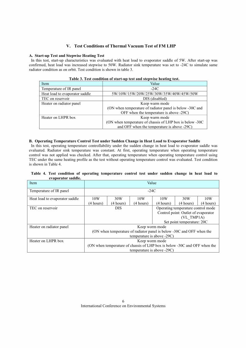
A. Start-up Test and Stepwise Heating Test In this test, start-up characteristics was evaluated with heat load to evaporator saddle of 5W. After start-up was
confirmed, heat load was increased stepwise to 50W. Radiator sink temperature was set to -24C to simulate same radiator condition as on orbit. Test condition is shown in table 3.
Table 3. Test condition of start-up test and stepwise heating test.
Item Value Temperature of IR panel -24C Heat load to evaporator saddle 5W/10W/15W/20W/25W/30W/35W/40W/45W/50W TEC on reservoir DIS (disabled) Heater on radiator panel Keep warm mode
(ON when temperature of radiator panel is below -30C and OFF when the temperature is above -29C)
Heater on LHPR box Keep warm mode (ON when temperature of chassis of LHP box is below -30C
and OFF when the temperature is above -29C)
B. Operating Temperature Control Test under Sudden Change in Heat Load to Evaporator Saddle In this test, operating temperature controllability under the sudden change in heat load to evaporator saddle was
evaluated. Radiator sink temperature was constant. At first, operating temperature when operating temperature control was not applied was checked. After that, operating temperature when operating temperature control using TEC under the same heating profile as the test without operating temperature control was evaluated. Test condition is shown in Table 4.
Table 4. Test condition of operating temperature control test under sudden change in heat load to
evaporator saddle. Item Value
Temperature of IR panel -24C
Heat load to evaporator saddle 10W (4 hours)
30W (4 hours)
10W (4 hours)
10W (4 hours)
30W (4 hours)
10W (4 hours)
TEC on reservoir DIS Operating temperature control mode Control point: Outlet of evaporator
(VL_TMP1A) Set point temperature: 20C
Heater on radiator panel Keep worm mode (ON when temperature of radiator panel is below -30C and OFF when the
temperature is above -29C) Heater on LHPR box Keep worm mode
(ON when temperature of chassis of LHP box is below -30C and OFF when the temperature is above -29C)

International Conference on Environmental Systems
7
C. Operating Temperature Control Test under Sudden Change in Radiator Condition In this test, operating temperature controllability under the sudden change in radiator condition was evaluated. Heat
load to evaporator saddle was constant. At first, operating temperature when operating temperature control was not applied was checked. After that, operating temperature when operating temperature control using TEC under the same test condition as the test without operating temperature control was evaluated. Test condition is shown in Table 5.
Table 5. Test condition of operating temperature control test under sudden change in radiator condition.
Item Value Temperature of IR panel -24C Heat load to evaporator saddle 15W TEC on reservoir DIS Operating temperature control mode
Control point: Outlet of evaporator (VL_TMP1A)
Set point temperature: 20C Heater on radiator panel Heating mode
10W (4 hours)
30W (4 hours)
10W (4 hours)
10W (4 hours)
30W (4 hours)
10W (4 hours)
Heater on LHPR box Keep warm mode (ON when temperature of chassis of LHP box is below -30C and OFF when
the temperature is above -29C)
D. Shut-down Test In this test, reservoir was heated using TEC when LHP was operating at heat load to evaporator of 15W to
evaluate the shut-down function. If shut-down was confirmed, heating of reservoir was stopped. After it was confirmed that LHP started up again, reservoir was heated again with same heat load to shut-down the LHP and it was evaluated if LHP could be shut-down three times consecutively.
Table 6. Test condition of shut-down test.
Item Value
Temperature of IR panel -45C
Heat load to evaporator saddle 15W
Heater on radiator panel Keep worm mode (ON when temperature of radiator panel is below -30C and
OFF when the temperature is above -29C) TEC on reservoir DIS ENA DIS ENA DIS ENA DIS
Input power to TEC N/A 5W N/A 5W N/A 5W N/A
Heater on LHPR box Keep warm mode (ON when temperature of chassis of LHP box is below -30C
and OFF when the temperature is above -29C)

International Conference on Environmental Systems
8
VI. Test Results and Discussions
A. Start-up Test and Stepwise Heating Test To evaluate the start-up characteristics at low heat load and the steady-state performance, experiment applying a
stepwise heat load was conducted under the test condition shown in Table 3. Initial temperature of LHP is about -30C. During the test, temperature of IR panel was controlled at -24C and the heat input from IR panel to LHP radiator was about 22W. Test result is shown in Figure 9. The LHP successfully started up at 5 W and operated stably at every heat load up to 50W.
Figure 9. Test results of start-up test and stepwise heating test.
B. Operating Temperature Control Test under Sudden Change in Heat Load to Evaporator Saddle To evaluate the controllability of operating temperature control using TEC, two kinds of tests were conducted. In
this test, temperature controllability under sudden change in heat load to evaporator saddle was evaluated. This test was conducted to check if LHP could control the temperature of a component of spacecraft even if heat dissipation from the component changed due to a change in operation mode. As shown in Table 4, heat load to evaporator saddle was changed cyclically between 10W and 30W, while radiator condition was constant. Heat input from IR panel to radiator panel by radiation was about 22W. Test result are shown in Figure 10. Figure 11 is a same graph as Figure 10, but only operating temperature is shown for clear vision. In the first half, TEC was disabled and operating temperature was not controlled. In the latter half, reservoir was heated or cooled by TEC to keep the operating temperature (temperature of evaporator outlet, “VL_TEMP1A” in Figure 8). Without TEC control, operating temperature changed about 15C in accordance with the change in heat load to evaporator saddle. When TEC control was applied, operating temperature was controlled at set point temperature (20C) with an error of ± 0.5degC.

International Conference on Environmental Systems
9
Figure 10. Results of operating temperature control test under sudden change in heat load
to evaporator saddle (1/2).
Figure 11. Results of operating temperature control test under sudden change in heat load
to evaporator saddle (2/2).

International Conference on Environmental Systems
10
C. Operating Temperature Control Test under Sudden Change in Radiator Condition To evaluate the controllability of operating temperature control using TEC, two kinds of tests were conducted. In
this test, temperature controllability under sudden change in radiator condition was evaluated. This test was conducted to check if LHP could control the temperature of a component of spacecraft even if radiator condition changed in orbit. As shown in Table 5, heat load to evaporator saddle was constant at 15W, while radiator condition changed cyclically. In addition to heat input from IR panel by radiation (22W), heat load were applied to radiator panel by electrical heaters attached on radiator panel as shown in Figure 8. Test result are shown in Figure 12. In the first half, TEC was disabled and operating temperature was not controlled. In the latter half, reservoir was heated or cooled by TEC to keep the operating temperature (temperature of evaporator outlet, “VL_TEMP1A” in Figure 8). Without TEC control, operating temperature changed about 10C in accordance with the change in radiator condition. When TEC control was applied, operating temperature was eventually controlled at set point temperature (20C) with an error of ± 0.5degC.
As described above, operating temperature was controlled with high accuracy eventually, but temperature overshoot of about 25C was confirmed right after TEC control was applied as shown in Figure 12. This is because parameters which were used in PID control to determine an input power to TEC were not proper. To check if operating temperature could be controlled without temperature overshoot by changing the PID parameters, reevaluation test was conducted. Test condition except for PID parameters was same as the test conducted from 16:00 to 19:00 in Figure 12. Test result is shown in Figure 13. It was confirmed that operating temperature could be controlled at set point temperature without temperature overshoot by setting proper PID parameters.
Figure 12. Results of operating temperature control test under sudden change in radiator condition (1/2).

International Conference on Environmental Systems
11
Figure 13. Results of operating temperature control test under sudden change in radiator condition (2/2).
D. Shut-down Test In this test, shut-down function of LHP was evaluated. This test was conducted to check if heat transfer of LHP
could be stopped intentionally by applying heat to reservoir by TEC. As shown in Table 6, 5W was input to TEC and reservoir was heated by TEC when LHP was operating at heat load to evaporator saddle of 15W. Test result is shown in Figure 14. Before applying power to TEC, LHP was operating stably. Right after reservoir was heated by TEC, vapor front went backward and vapor generated at evaporator flew back to liquid line. These phenomena indicate circulation of working fluid is stopped. In addition to these phenomena, the temperature of evaporator, which was around 5C when LHP was operating, suddenly increased right after heating of reservoir started. This indicates heat which had been transferred to radiator started being used to increase the temperature of evaporator. Judging from these phenomena, it was confirmed that LHP could be successfully shut down by applying heat to reservoir by TEC. After confirming LHP was shut down, heating of reservoir was stopped. Right after heating of reservoir was stopped, LHP started up and the circulation of working fluid was resumed. By repeating same procedure, three times consecutive shut-down and re-start were confirmed.

International Conference on Environmental Systems
12
Figure 14. Results of shut-down test.
VII. Conclusion Before adopting LHPs in thermal control system of practical spacecraft mission, on-orbit experiment of LHP
radiator is planned to confirm the thermal performance and thermal characteristics under -g condition. On-orbit experiment plan of LHP radiator system was introduced. And the results of thermal vacuum test of FM LHP were also introduced. It was confirmed that FM LHP fulfilled all specified requirements and FM LHP showed good performance in 1-g condition. FM LHP will be launched in autumn in 2018 by H-IIA rocket and transported to ISS by HTV-7 (H-II Transfer Vehicle). On-orbit experiment will be conducted by the end of 2018.
References 1J. Ku, “Operating Characteristics of Loop Heat Pipes”, SAE Paper No.1999-01-2007, 1999. 2Y.F. Maidanik and Y.G. Fershtater, “Theoretical Basis and Classification of Loop Heat Pipes and Capillary Pumped Loops”, Proc. 10th International Heat Pipe Conference, X-7, pp.1-15, 1997. 3T.T. Hoang and J. Ku, “Heat and Mass Transfer in Loop Heat Pipes”, Proceedings of 2003 ASME Summer Heat Transfer Conference, July 21–23, 2003, Las Vegas, Nevada, USA. 4S. Oost, M. Dubois, G. Bedaert, B. Moschetti and M. Amidies, “High Performance Capillary Loop, Operation Mapping and Applications on STENTOR”, SAE Paper No.961565, 1996. 5E.W. Grob, “System Accommodation of Propylene Loop Heat Pipes for the Geoscience Laser Altimeter System (GLAS) Instrument”, SAE Paper No.2001-01-2263, 2001. 6H. Nagai and S. Ueno, “Performance Evaluation of Double-condenser Loop Heat Pipe onboard Monitor of All-sky X-ray Image (MAXI) in Thermal Vacuum Testing”, SAE Paper No.2005-01-2939, 2005. 7H. Kawasaki, T. Yabe, A. Okamoto, H. Ishikawa, T. Nomura, and Y. Saito, ”Characteristics of Reservoir Embedded Loop Heat Pipe in an Orbital Environment in the First Year”, SAE Paper No.2009-01-2518, 2009. 8A. Okamoto, R. Hatakenaka and M. Murakami, “Visualization of a Loop Heat Pipe Using Neutron Radiography”, Heat Pipe Science and Technology 21-4), pp.161-172, 2011.