On Board Computers - ULiege · December 2017 Avionics Overview for ULG 26 MilBus Basics Bus...
49
On Board Computers December 2017
Transcript of On Board Computers - ULiege · December 2017 Avionics Overview for ULG 26 MilBus Basics Bus...

On Board Computers
December 2017

December 2017 Avionics Overview for ULG 2
Avionics
• The Avionics Embedded System (AES) includes the hardware
(processor, communication buses, equipments, instruments) and software required for the command & control of the spacecraft, its telecommand and telemetry handling, its failure detection, isolation and recovery and all the mission and vehicle management functions including all functional chains. The AES is the brain of the spacecraft and therefore is a vital organ for the execution of onboard functions. It represents today between 30 and 70 % of the platform non-recurrent development costs (50% in average for an ESA mission).
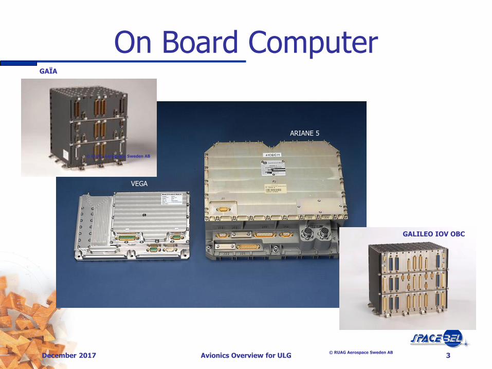
On Board Computer
December 2017 Avionics Overview for ULG 3
VEGA
ARIANE 5
GALILEO IOV OBC
© RUAG Aerospace Sweden AB
GAÏA
© RUAG Aerospace Sweden AB

Payload Data Handling Unit
December 2017 Avionics Overview for ULG 4
© EADS Astrium
PDHU
© EADS Astrium

Advanced Data & Power Mgt System
December 2017 Avionics Overview for ULG 5
The LEON processor board (unfolded)
ADPMS under test
1,5 Watt
300 gram

Avionics
December 2017 Avionics Overview for ULG 6

CCSDS
Avionics: Overview
Ground Segment
Platform Equipments
Payload Instruments
Command (CMD)
Control (CTRL)
PCDU
Telecommand (TC)
Telemetry (TM)
Downlink (DL)
Uplink (UL)
Spacelink
Reception (Rx)
Transmission (Tx)
Command (CMD) Control
(CTRL) Data (DAT)
•AOCS Sensors •PWR System •THERM System •RF System •…
•Optical •Scientific •Telecom •Radionavigation •…
OBC
OBSW
December 2017 7 Avionics Overview for ULG

December 2017 Avionics Overview for ULG 8
Avionics: Overview (cont.)
CDMU
Ground Segment
Platform Equipments
Payload Instruments
PCDU
MM
Low Throughput (e.g. S Band)
High Throughput (e.g. X Band)
PDHU/ MMFU
Remote Terminal
Unit

Avionics: Redundancy
December 2017 Avionics Overview for ULG 9

Avionics: Redundancy
December 2017 Avionics Overview for ULG 10
Nominal Equipment
ON
Hot Redundancy
Cold Redundancy
Lukewarm Redundancy
Nominal Equipment
ON
Nominal Equipment
ON
Redundant Equipment
ON
Redundant Equipment
OFF
Redundant Equipment STANDBY
Context Memory
Both nominal and redundant equipment are On and running in parallel Mandatory if no way to select redundant equipment Advantage: no service interruption Drawback: reliability, consumption
wd cmd
Periodic save Last saved
Reconfiguration Emergency
Module
Nominal equipment is On and running while Redundant equipment if Off and not running Advantage: higher reliability Drawback: failover time
Nominal equipment is On and running while Redundant equipment if On but Halted and not running Typical of On Board Computer

December 2017 Avionics Overview for ULG 11
Avionics: Hostile Environment
• Temperature: extreme conditions
• Temperature range solar cells -150 +100 °C
• Packaging, isolation and heaters: reduction to -20 +50 °C
• Commercial electronics don’t fit the bill : 0 70 °C (mil range -55 +125 °C)
• Ion radiation : electron, proton, heavy ion (solar flare, van Allen belts)
• Cumulated Effect:
• Modification of the component characteristics
• Single Event Effects:
• SET: Single Event Transient (glitches) non destructive
• SEU: Single Event Upset (swap) non destructive
• SEL: Single Event Latchup (CMOS)
• SEB: Single Event Burnout (MOSFET) destructive
• SEGR: Single Event Gate Rupture destructive

December 2017 Avionics Overview for ULG 12
• Radiation Protections • Shielding • Box design • Positioning in the S/C • Technology choices • Build in electronic protection
• Fault Tolerance • Ability to support temporary or definitive modification or suppression of
functionality • Redondancy
• Processing: Spatial or Temporal Redundancy and Majority Voting • Duplicate the system: when a system is faulty, switch on the other one • Permit to eliminate the faulty system from the decision path (TMR technology) • Data Redundancy through coding, (RS, CRC, etc)
• Error Detection and Correction (EDAC) on memory • Memory scrubbing to “clean” changed memory
Avionics: Protection Means

ON BOARD PROCESSORS
December 2017 Avionics Overview for ULG 13
December 2017 Avionics Overview for ULG 14
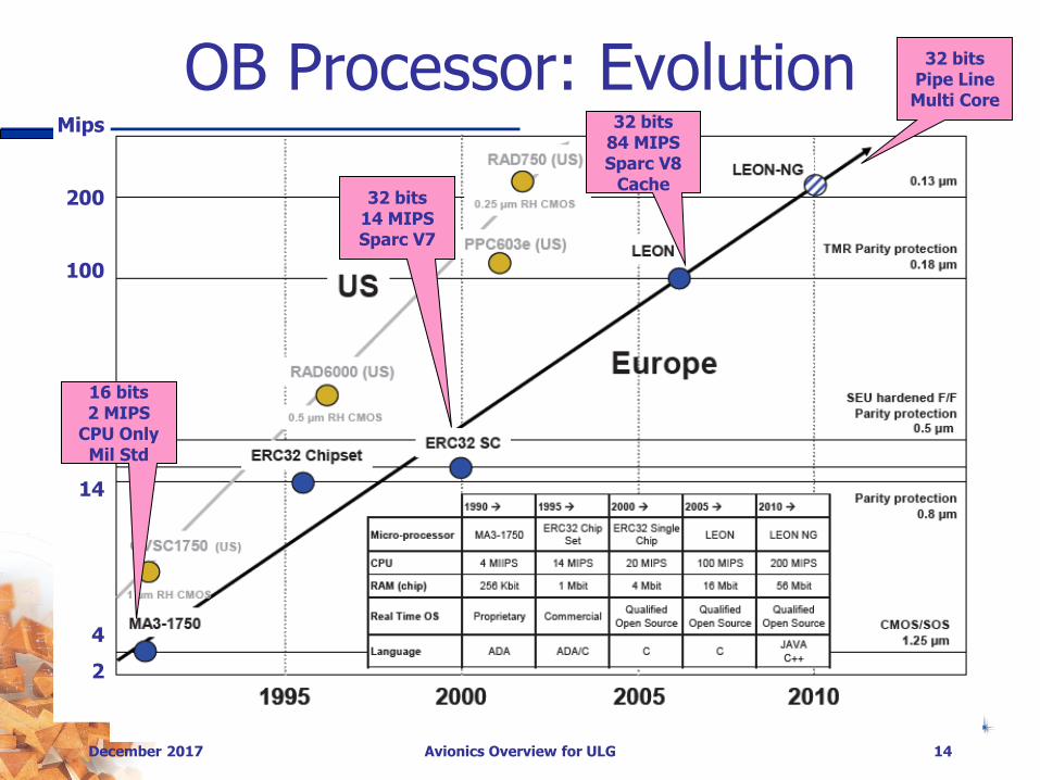
OB Processor: Evolution Mips
200
100
50
14
4
2
16 bits 2 MIPS
CPU Only Mil Std
32 bits 14 MIPS Sparc V7
32 bits 84 MIPS Sparc V8
Cache
32 bits Pipe Line Multi Core

OB Processor: Frequency Increase
December 2017 Avionics Overview for ULG 15
Increase of the processor clock frequency is a method of achieving higher performance. This however leads to increase of processor power dissipation figure.

OBP: Multi Core
December 2017 Avionics Overview for ULG 16
Multi-core architecture is an alternative architectural solution that has the main advantage to increase the platform performance without increasing the power consumption

OBP: Multi Processor
December 2017 Avionics Overview for ULG 17
Multi-processor architecture is yet another alternative architectural solution that allows for distributing the processing (e.g. image processing, complex gnc algorithms), on specialized, dedicated hardware (e.g. µp, dsp, fpga)

Processors vs Cores
December 2017 Avionics Overview for ULG 18
Memory
Processor
Memory
Processor
Memory
Processor Core
Memory
Core Core
Memory
Processor
Memory
Processor
Memory
Processor Core
Memory
Core Core
Cache Cache Cache Cache Cache Cache
Cache Coherency Issue
Bus Bottleneck Issue

SMP vs AMP
December 2017 Avionics Overview for ULG 19
Core Core Core
RTOS
Thread Thread Thread Thread
Core Core Core
RTOS
Thread Thread Thread
RTOS RTOS
Thread Thread Thread
Thread Thread Thread
Core Core Core
RTOS
Thread Thread Thread
Thread Thread Thread
Thread Thread Thread
Symmetric Multi Processing Asymmetric Multi Processing Supervised Asymmetric Multi Processing

OB MEMORY
December 2017 Avionics Overview for ULG 20

December 2017 Avionics Overview for ULG 21
On Board Computer Memory • Memory types
• PROM (Programmable Read Only Memory)
16 – 256 KB Board boot and init SW
• EEPROM (Electrically Erasable Programmable Read Only Memory)
2 – 8 MB the mission SW boot container, also used for safeguard
• SRAM (Static Random Access Memory)
4 – 16 MB; the workplace that contains executing SW and variables
• SDRAM (Synchronous Dynamic Random Access Memory) 16 to 512 MB slower RAM typically used for mass storage
SRAM: data bit is stored in the state of a flip-flop (transistor logic - No power for Data Retention)
DRAM: data bit is stored in the electric charge of a nano capacitor (Frequent Refresh Cycles, Volatile)
ROM: uses a metal mask to permanently enable/disable selected transistors instead of storing a charge in them FLASH: a kind of EEPROM erased and written in large blocks, read in a random access fashion (Non Volatile)
MRAM: Magnetoresistive Random Access Memory (non-volatile magnetic storage)
SDRAM, DDR SDRAM, FeRAM, MRAM, CRAM, PRAM

December 2017 Avionics Overview for ULG 22
On Board Data Storage
• Playing Tapes Storage (Till 2000) • Mass Memory based on back and forward magnetic tapes.
• Record in forward and play back in reverse (no time to rewind)
• Robust to power failures
• Solid State Mass Memory (Nowadays) • Processor board can have 512 MB SDRAM Mass memory
• Extra board could hold a GB (with battery back-up)
• Very big Mass Memory units with almost unlimited size can be made in a very compact way (SDRAM or flash EPROM)
• Interface through fast serial links (E.g. SpaceWire)
• Mostly used for high resolution image satellites (e.g. 12 TB at EOL for Sentinel 2)
Storage Capacity, Transfer Data Rate,
Power for Data Retention, Power for Data Access, Write Endurance, Sensitivity to Single Event Effects
High Speed Error Detection, High Speed Error Correction, File Management System, Hardware Software Partitioning, Simultaneous Accesses

OB COMMUNICATIONS
December 2017 Avionics Overview for ULG 23

December 2017 Avionics Overview for ULG 24
On Board Communications Budget Flow (Proba 2) From -> To Mbps
TC segments Ground Spacecraft 2
TM/TC CLCW protocol feedback TC/TM channels 0,01
TM Packets TM ground 2 x 66
AOCS control OBSW Eqts 0,1
AOCS telemetry Eqts OBSW 0,1
Payload control OBSW Payload 0,1
Payload Telemetry Payload OBSW 0,01
Spacecraft SW housekeeping Eqts OBSW 0,01
REM context writing OBSW REM 0,01
REM Watchdog kicking REM OBSW 0,01
PCM/PDM control OBSW PCM/PDM 0,01
PCM/PDM Telemetry PCM/PDM OBSW 0,01
Spacecraft HW housekeeping Eqts OBSW 0,01
REM housekeeping REM (TM) ground 0,01
Payload Data TM packets Payload TM 20

December 2017 Avionics Overview for ULG 25
On Board Communication On Board Communications
Digital Analog
Multi Drop Buses Point-to-Point Links Point-to-point
Spacewire* Mil-Bus*
Serial Line Digital Converter Switchable Outputs Statuses
I2C CanBus*
On going studies investigate on board wireless communications
Total harness weight (cables and connectors) may reach 6 to 10% of total satellite mass
Single Master Multi Master
OBDH RS-422 RS- 485
*may be redundant
PacketWire
Trade offs to be made: •Power consumption •Silicon surface, board surface •Connectors and wiring harness (6 to 10 % of weight of a satellite) •Performance (throughput, response time) •Isolation and fault propagation •Intelligence required at slave end •Required processing overhead

December 2017 Avionics Overview for ULG 26
MilBus Basics
Bus Controller
Remote Terminal
Remote Terminal
Equipment
Equipment Equipment Equipment
Nominal
Redundant • From aircraft industry • Mil-Std-1553-B Standard • Multi Drop Bus • Master/Slave • Single cable • Half Duplex • Asynchronous • Redundant (cross strapping) • 1 Mbps (650 Kbps effective) • Manchester Bi Phase Coding
Rx Cmd Data Word Data Word …………… Data Word Status Word BC RT Answer Time
12 µs Inter Msg
4 µs
Answer Time 12 µs Tx Cmd Data Word …………… Data Word RT BC
Inter Msg 4 µs Data Word Status Word
Answer Time 12 µs Tx Cmd …………… Data Word RT RT
Inter Msg 4 µs Data Word Rx Cmd Status Word Status Word
Answer Time 12 µs
1 Msg = 1 to 32 Words
1 Word = 16 Bits
1 2 3 4 5 6 7 8 9 10 11 12 13 14 15 16 17 18 19 20
P
P Data
RT @ T/R Sub @ / Mode Code # Words
RT @ Err Inst Svc Reserved Bsy P
CMD
DAT
STS

December 2017 Avionics Overview for ULG 27
Spacewire Basics
• High Speed Serial Link • Fairly Simple • High data rate (up to 400 Mbps) • Low power consumption
• Promoted by ESA, based on IEEE 1533, DS
Link, Transputer Technology • Physical interface requires LVDS-tranceivers
• Packet based <Destination
Address><Cargo><End_of_Packet>
• SpaceWire Router connects a number of SpaceWire link interfaces (receiver to transmitter ports)
• Group Adaptive Routing: group of links may be configure to increase throughput (bandwidth sharing) or fault tolerance
• Allow for different topologies following use needs

December 2017 Avionics Overview for ULG 28
CAN Bus Basic
• Controller Area Network (CAN)
• Automotive
• Bosch / Intel

December 2017 Avionics Overview for ULG 29
Ethernet Basics
• Deterministic Ethernet
• AFDX (Avionics Full Duplex Switched Ethernet)
• TT Ethernet (Time Trigered Ethernet)

December 2017 Avionics Overview for ULG 30
Space Link Basic
• Radio Frequency
• L-Band, S-Band, X-Band (Science Data)
• Delay and Disruption Tolerant
• Tracking and Ranging
• Telecommand Uplink
• Telemetry Downlink

GND COMMUNICATION
December 2017 Avionics Overview for ULG 31

December 2017 Avionics Overview for ULG 32
TC Telecommands
• Receives TC bitstream from antenna/receiver • Hardware decoding of TC data streams:
• Decoding bitstreams, error detection and correction, de-randomisation, overrun detection
• Isolation of CLTU Command link Transmission Unit (which can contain several TC’s)
• Generate FAR Frame Analysis Report for CLCW, send to TM module (COP-1 protocol)
• Sends emergency TC’s directly to associated pulse generators
• Sending of TC’s to SW decoder
• Pulse generation (Pulse Distribution Unit) • Generates and distributes pulses without
software intervention (reliability, precision)

December 2017 Avionics Overview for ULG 33
TM Telemetry - Sources
• Sources of Telemetry allocated to separate VC Virtual Channels • Hardware generated TM’s:
• Emergency telemetry: reporting of essential Telemetry: SW independent – low bandwidth <0,2 Kbps
• Context memory (REM) dumps - < 6Kbps
• Processor generated TM • Event driven TM’s, housekeeping, off-line and Mass Memory
data… See SW design
• TM from other sources (payloads, instruments) that inject directly TM without OBSW intervention
• Idle packet generation: to keep the space link operational and synchronised if no real TM is available
• VCM (Virtual Channels Multiplexer): • Time multiplexes VC’s according to BAT (Bandwidth
Allocation Table) on a per frame basis

December 2017 Avionics Overview for ULG 34
Telemetry Encoder
• Handles the serialised TM frames:
• Addition of Reed-Solomon Error Detection and Correction symbols
• Pseudo-randomisation (to ensure bit transition density and avoid Tx DC components)
• Optional Non-Return-to-Zero Mark encoding
• Convolutional Encoding, such as Viterbi (doubles the bit rate)
• Optional Split-Phase Level modulator (doubles bit rate)
• Feed bitstream to radio amplifier/transmitter

December 2017 Avionics Overview for ULG 35
OBC: System on Chip • Saab Space, available in 2008 in Atmel ATC18RHA
radiation hard 180 nm standard cell ASIC technology
• LEON2-FT Fault Tolerant SPARC V8 processor, 86 MIPS@100 MHz + FPU
• SPARC V8 Reference Memory Management Unit (MMU)
• Caches: 32 KB instruction, 16 KB data cache
• Extended Debug Support Unit (E-DSU) with 4096 trace lines
• EDAC and automatic scrubbing on large SDRAM, Memory Copy Controller
• 3 High-Speed UART’s
• Three MIL-STD-1553B bus interfaces
• OBDH bus Central Terminal
• 3 PacketWire Receivers & Transmitters
• 8 ECSS-E-50-12A SpaceWire Interfaces capable up to 200 MHz/160 Mbps, Hardware support for Remote Memory Access Protocol.
• 2 Controller Area Network (CAN) interfaces supporting up to 1 Mbps

December 2017 Avionics Overview for ULG 36
Reconfiguration Module
• Manages:
• The watchdog and associated computer reset and switch-over logic • The active and cold standby computer • The OBSW version to be loaded at start-up
• It can as well contain:
• Context memory: • Serves as memory for time stamped logs of reconfiguration
module, boot and application SW • Is not reset by a computer boot and regularly transferred to
the ground. • Emergency TC hardware decoder and pulse generator • Central date and time system

OBP EXAMPLES
December 2017 Avionics Overview for ULG 37

December 2017 Avionics Overview for ULG 38
OBP : LEON2 • Synthesisable Open Source VHDL
model of a 32-bit SPARC V8
• Caches: 16 KB Data, 32 KB instructions
• Self standing computer: need only external clock and memory
• 2 timers + watchdog
• 2 UART, 32 parallel I/O
• Fault tolerant (parity, EDAC, TMR)
• Separate DSU (Debug Serial Unit) with normal serial line interface and transaction/instruction trace buffer with 512 entries
• Integrated PCI interface (50 % of chip)
• Virtual latchup free (70 MeV.cm2/mg)
• Radiation up to 300 Krads (Si)
SPARC = Scalable Processor ARChitecture = RISC (Reduced Instruction Set Computer) – 32 bit RISC = Simple instruction set, simple CPU, target = 1 instruction per cycle (without memory R/W)
simple compiler, but needs 40 % bigger code size, better code optimisation SUN SPARC strong points: One of the best performance & power figures per gate
SPARC architecture is no longer evolving but still holds up against other CPU designs

OBP: Dual Core LEON3
December 2017 Avionics Overview for ULG 39
GR712RC Architecture © Aeroflex Gaisler AB

OBP: Quad Core LEON4
December 2017 Avionics Overview for ULG 40
NGMP Architecture © Aeroflex Gaisler AB

AVIONICS EXAMPLES
December 2017 Avionics Overview for ULG 41

December 2017 Avionics Overview for ULG 42
PROBA 1
DHS
AOCS I/F
Reaction Wheels
(4)
Magnetometers
(2)
Magnetotorquers
(4)
PCS
GPS Receiver
Star Tracker (2)
Head
Head
Receivers (2)Transmitters
(2)
SREM
DEBIE
PPU
CHRIS
Imagers
Other
Payloads
BatterySolar
Array
Power line
Digital Control line
Proba 1
•Centralized (star) architecture
+ Simple design, direct connection with the OBC
+ Well adapted to off the shelf equipment integration
- Modularity
- Harness
• Mass:
•Structure
•Instruments
•Power
•AOCS
•Avionic & data
processing
8.5kg8.5kg
• Harness
• RF6kg6kg
8kg8kg
29kg29kg
24kg24kg
9.5kg9.5kg
12kg12kg

December 2017 Avionics Overview for ULG 43
Bus architecture:
+ std protocol and communication schemes for all nodes
+ modularity/ testablity
+ Bus traffic solved with central arbitration (CAN, 1553) or protocal arbitration (CAN,
Ethernet)
-I/F component must be developped
- Bus redundancy

December 2017 Avionics Overview for ULG 44
PROBA 2 Architecture
Nominal PCI BUS
DATA
ACQUISITION
MODULE
TELEMETRY &
TELECOMMAND
MODULE
SPACECRAFT
INTERFACE
MODULE
MAIN
PROCESSOR
MODULE
CAMERA &
MASS MEMORY
MODULE
PCI
ARBITER
Redundant PCI BUS
DATA
ACQUISITION
MODULE
TELEMETRY &
TELECOMMAND
MODULE
SPACECRAFT
INTERFACE
MODULE
MAIN
PROCESSOR
MODULE
CAMERA &
MASS MEMORY
MODULE
PCI
ARBITER
I/O BUS
EMERGENCY
TELECOMMAND
MODULE
•Proba 2
• Internal busses (industrial standards)
• Main Boards/ generic communication (analog/
digital I/Os, serial lines)

December 2017 Avionics Overview for ULG 45
Backplane data throughput
up to 1 GBps
Multi processor support
Processor board - 100MIPS - 64 Mbyte SDRAM - 4 Mbyte SRAM - 4 Mbyte Flash - 256 kByte Prom Telecommand
- 2 Mbps uplink capability - 4 virtual channels or more - configurable N° of MAP-ID
- 56 CPDU channels
Telemetry - 100 Mbps downlink - 5 virtual channels - 2 packetwire inputs - full encoding
Mass memory - 4 Gbit - with EDAC
Context memory - 128 kbyte - with EDAC
Communication Interfaces - Up to 25 UART channels - Up to 6 TTC-B-01 channels - a camera interface with frame grabber - 2 packetwires
Analogue Interfaces - Up to 80 analogue inputs - Up to 32 temperature inputs
Time interfaces - 8 programmable clock outputs - 3 clock datation inputs
Power conditioning - Up to 300W satellite peak power - Up to 6 solar sections
Power distribution - 24 outputs of 28V / 50W - current protected with auto restart - switchable or non-switchable - battery undervoltage protected with auto switch off
H/W generated emergency telemetry
Centralised time
synchronisation
H/W recovery
TC decoder
Budgets: Mass 13 kg Volume 455x160x267mm Power 17 W
1 failure tolerant system
Proba2: Main Facts & Figures

Avionics : Proba V
December 2017 Avionics Overview for ULG 46

December 2017 Avionics Overview for ULG 47
Avionics : Proba 3 PROPULSION
Nominal
AOCS & FF ADPMS
DWI+FLS
ULLIS
Comms
Payload
Coronagraph
electronics
Primary Tx
Primary Rx
RF
DU
Redundant Tx
Redundant Rx
S-b
an
d a
nte
nn
as
Power
Li-ion Battery
Solar arrays
Umbilical to launcher
Umbilical to Occulter
Power & Data Test I/F
Mechanisms
Solar array release mechanism (primary)
SO 28V
SO 28V
TC I/F RS422 UART
NSO 28V
TC I/F RS422 UART
Clock RS422 UART
TM I/F RS422 UART
SO 28V
NSO 28V
Clock
TM I/F RS422 UART
ImageWire
RS422 UART (TBC)Coronagraph
optics & telescope
DMS
PMS
Primary
DMS
MPM
MCPM
TTM
SIM
DAM0
DAM1
REM
PSM
PDM0
PCM
Redundant
DMS
MPM
MCPM
TTM
SIM
DAM0
DAM1Temp sensors 1 to 12 (TBC) on optical bench
Heaters 1 to 6 (TBC) on optical bench
RS422 UART
MIL-STD-1553
SO 28V
SO 28V
ASC
CHU1
CHU2
CHU3
DPU
CPU1
Cro
ss c
ou
plin
g
CPU1SO 28V
RS422 UART
Clock
SO 28V
RS422 UART
Clock
SO 28V
RS422 UART
SO 28V
RS422 UART
RS422 UART
RS422 UART
SO 28V
Coronagraph spacecraft
initial date
C:\Documents and Settings\bja\Mina dokument\PROBA-3_Avionics_block_diagram.VSD
page 1 of 2
CSC Diagram
Avionics Concept for PROBA3
print date
last change07-11-08 09:25
07-11-08 09:25
07-11-08 09:25
dd.mm.yyAllA
datechangesissue EN PM PA
Alex Palacioscreator
Dump resistor
SO 28V
SO 28V
SO 28V
RS422 UART
Thermal
I/F boxSO 28V
RS422 UART
1N 3DOF - Monoprop (HPGP)
Valve 8
Valve 1
...
10mN 6DOF - Marotta
Valve 16
Valve 1
...
SO 28V
RS422 UART
SO 28V
RS422 UART
SO 28V
RS422 UART
Solar array release mechanism (redundant)Safe & Arm
Safe & Arm
Propulsion DAM
DAM2 DAM2
RS422 UART
PDM1
PDM2
PDM3
PDM4
PDM5
Body panel x 6X 6
RF Metrology
Primary RF metrology
BB
Tx
Rx
Rf s
witc
h
Redundant RF metrology
...
BB
Tx
Rx
Rf s
witc
h
7 S
-ba
nd
an
ten
na
s
RS422 UART
SO 28V
RS422 UART
RS422 UART
SO 28V
RS422 UART
X 3
X 3
X 4
X 4
X 3
X 3
PowerLow speed data linkHigh speed data linkAnalog signalDigital signalClock
Mission-Critical Item
X 2
X 2
500µN EP 2DOF - MiDGITS
RF Supply
PCCS XFCU
RF Supply
neutraliser
RS422 UART
X 4
X 6
Thermal control
Heater branches x 2 (for redundancy)
ASSG-RTU
Acc I/F
electronics
SAS I/F
electronics
SPS I/F
electronics
Redundant
Acc I/F
electronics
SAS I/F
electronics
SPS I/F
electronics
Accelerometers
Acc1
Acc5
...
Sun sensor 1*4
SPS
Sensors
1 to 4Amplifier
GRW-RTU
Nominal
Redundant
Gyros
Gyro1
Gyro5
...
Gyro I/F
electronics
Gyro I/F
electronics
RW1
RW4
...
RW I/F
electronics
RW I/F
electronics
RS422 UART
Nom GPS
receiverLNA
Red GPS
receiverLNA
PROP-RTU
Nominal
Redundant
I/F electronics
I/F electronics
PROP-RTU
Nominal
Redundant
I/F electronics
I/F electronics
EP-RTU
Nominal
Redundant
I/F electronics
I/F electronics
SO 28V
RS422 UART
PTC-RTU
Redundant
Quick-nut
Pyro
22 Thermistor
I/F electronics
4 LED drivers
18 Heaters
I/F electronics
Nominal
Quick-nut
Pyro
22 Thermistor
I/F electronics
4 LED drivers
18 Heaters
I/F electronics
SO 28V
RS422 UART
SO 28V
RS422 UART
Nom GPS PPS
RS422 UART
RS422 UART
Red GPS PPS
2 x 4 LEDs for
RDW
Courtesy QinetiQ Space

December 2017 Avionics Overview for ULG 48
PROBA 3: PROPULSION
AOCS & FF ADPMS
Comms
Payload
DARA
Primary Tx
Primary Rx
RF
DU
Redundant Tx
Redundant Rx
S-b
an
d a
nte
nn
as
Umbilical to Coronagraph
Power & Data Test I/F
SO 28V
SO 28V
TC I/F RS422 UART
NSO 28V
TC I/F RS422 UART
Clock RS422 UART
TM I/F RS422 UART
SO 28V
NSO 28V
Clock
TM I/F RS422 UART
RS422 UART (TBC)
DMS
PMS
Primary
DMS
MPM
MCPM
TTM
SIM
DAM0
DAM1
REM
PSM
PDM0
PCM
Redundant
DMS
MPM
MCPM
TTM
SIM
DAM0
DAM1
Occulter spacecraft
initial date
C:\Documents and Settings\bja\Mina dokument\PROBA-3_Avionics_block_diagram.VSD
page 2 of 2
OSC Diagram
Avionics Concept for PROBA3
print date
last change07-11-08 09:25
07-11-08 09:25
07-11-08 09:26
dd.mm.yyAllA
datechangesissue EN PM PA
Alex Palacioscreator
10mN 6DOF - Marotta
Valve 8
Valve 1
...
Propulsion DAM
PDM1
PDM2
PDM3
PDM4
PDM5
RF Metrology
Primary RF metrology
BB
Tx
Rx
Rf s
witc
h
Redundant RF metrology
...
BB
Tx
Rx
Rf s
witc
h
7 S
-ba
nd
an
ten
na
s
RS422 UART
SO 28V
RS422 UART
RS422 UART
SO 28V
RS422 UART
X 4
X 4
X 3
X 3
X 2
X 2
NSO 28V (thermal)
2 x 4 LEDs for
OPS
10-1000µN 6DOF - Nanospace Coldgas
Pod 1
Pod 4
...
DAM2 DAM2
RS422 UART RS422 UART
Power
Li-ion Battery
Solar arrays
Dump resistor
X 3
X 3
X 6
Body panel x 6X 6 PowerLow speed data linkHigh speed data linkAnalog signalDigital signalClock
Mission-Critical Item
SO 28V
RS422 UART
SO 28V
RS422 UART
SO 28V
RS422 UART
SO 28V
RS422 UART
PROP-RTU
Nominal
Redundant
I/F electronics
I/F electronics
PROP-RTU
Nominal
Redundant
I/F electronics
I/F electronics
Thermal control
Heater branches x 2 (for redundancy)
PTC-RTU
Redundant
Quick-nut
Pyro
22 Thermistor
I/F electronics
4 LED drivers
18 Heaters
I/F electronics
Nominal
Quick-nut
Pyro
22 Thermistor
I/F electronics
4 LED drivers
18 Heaters
I/F electronics
ASC
CHU1
CHU2
CHU3
DPU
CPU1
Cro
ss c
ou
plin
g
CPU1SO 28V
RS422 UART
Clock
SO 28V
RS422 UART
Clock
RS422 UART
SO 28V
SO 28V
SO 28V
RS422 UART
ASSG-RTU
Nominal
Acc I/F
electronics
SAS I/F
electronics
SPS I/F
electronics
Redundant
Acc I/F
electronics
SAS I/F
electronics
SPS I/F
electronics
Accelerometers
Acc1
Acc5
...
Sun sensor 1*4
GRW-RTU
Nominal
Redundant
Gyros
Gyro1
Gyro5
...
Gyro I/F
electronics
Gyro I/F
electronics
RW1
RW4
...
RW I/F
electronics
RW I/F
electronics
RS422 UART
Nom GPS
receiverLNA
Red GPS
receiverLNA
RS422 UART
SO 28V
Nom GPS PPS
RS422 UART
RS422 UART
Red GPS PPS
SO 28V
RS422 UART
SO 28V
RS422 UART
Courtesy QinetiQ Space

December 2017 Avionics Overview for ULG 49