An Isolated Multiport DC - DC Converter for Simultaneous ...

ISSN (Online) : 2319 - 8753 ISSN (Print) : 2347 - 6710
International Journal of Innovative Research in Science, Engineering and Technology
Volume 3, Special Issue 3, March 2014
2014 International Conference on Innovations in Engineering and Technology (ICIET’14)
On 21st & 22nd March Organized by
K.L.N. College of Engineering, Madurai, Tamil Nadu, India
Copyright to IJIRSET www.ijirset.com 2713 M.R. Thansekhar and N. Balaji (Eds.): ICIET’14
Integration and Distribution of Renewable Sources in
DC Micro Grid With Energy Storage System Ramji Tiwari
1, M. Anantha Kumar
2
1PG Student, Sri Krishna College Of Engineering And Technology,Coimbatore, India.
2Assistant Professor, Sri Krishna College Of Engineering And Technology,Coimbatore, India.
ABSTRACT--This Paper presents a dynamic modelling
of a DC Micro grid which has an Solar and Wind as an
Distributed Energy Sources (DES).A Multi Port DC –DC
converter is used to integrate the renewable sources to the
DC bus. A Direct Driven Permanent Magnet Synchronous
Generator is used with a variable speed control technique
so that it can extract high wind energy below the rated
speed of the wind. The both solar and wind changes
according to the load requirement and also the
availability. An Energy Storage Element such as Battery
is also integrated with the DC bus so that it can store
energy when present in excess.
INDEX TERMS – DC Micro grid, Photovoltaic power
systems, power conversions , wind power generations.
I-INTRODUCTION
DC Distributed energy system (DES) has the
advantage to interact with Renewable Energy source due
to simplicity and efficiency. Distributed energy resources
include PV and fuel cell, which generates DC voltage and
wind turbine and internal combustion engine which
produces AC voltage. All of these resources have to be
interfaced with a DC bus and feed power to the load,
therefore dc-dc or ac-dc converters are used. The Bus can
balance the voltage between the energy storage system
and the DC load. Power Electronics Converter is used to
interface the load and the Renewable Source. A common
DC Bus is shared between the loads and to store the
energy.
The conventional electrical system in place today sees
our electrical devices powered by AC mains. But as
renewable technologies such as solar photovoltaic and
wind power become more prevalent at a household level,
DC Micro grid could be a cheaper and more efficient
alternative.
DC-DC converters are essential in DC Distribution
Systems since they connect not only Dc sources but also
DC energy storage Elements.This Paper focus on
developing a DC bus for a Distributed PV and Wind
Applications.
In this system the energy sources are Solar and Wind
for a Distributed Energy system, and energy storage
elements such as Batteries. In this system a Multi port DC
converter is used such that it can interface PV and Wind
with their respective MPPT to the DC bus and also to the
battery. By using such kind of converters the efficiency
of the DES is increased
and it is cost effective. The converter consists of a Bi –
Directional port for the batteries so that it can charge and
discharge randomly.
II-PROPOSED MICROGRID ARCHITECTURE
Fig. 1 shows the overall architecture of the proposed
Micro grid with wind and PV sources [1]. The main
sources, of wind and solar radiation are converted into
electrical energy by wind generator and the array of PV
modules. To combine these input sources a Multiport DC
Converter is used. Multiport DC Converter is used
because it has effective MPP tracking in PV System and
effective control of input current in grid connection
system. They provide a cost effective and flexible method

Integration and Distribution of Renewable Sources in DC Micro grid with Energy
Copyright to IJIRSET www.ijirset.com 2714 M.R. Thansekhar and N. Balaji (Eds.): ICIET’14
to interface many such Renewable sources since they have multiple ports [3].
Fig:1 overall architecture of the proposed Micro grid system
In addition, DC system is used because it is present in
abundant and efficiency is higher than the AC system. An
Energy Storage System (ESS) is also connected to main
DC bus in order to support the local loads for the
uninterrupted power supply.
Depending upon applications the local loads requires
different voltage levels which is obtained by the using DC
– DC converters. The Converter either buck or boost the
voltage obtained from the DC bus and it is given as an
input to the load.
III. MODELLING OF PROPOSED MICROGRID
Modelling of various components of proposed system
are as follows.
A. PV Model
The study of PV modelling is proposed in Fig. 2
[4].
Fig. 2 : solar panel equivalent circuit

Integration and Distribution of Renewable Sources in DC Micro grid with Energy
Copyright to IJIRSET www.ijirset.com 2715 M.R. Thansekhar and N. Balaji (Eds.): ICIET’14
The parameters required by the PV module are
number of PV modules, PV array open circuit voltage
(Voc), Short Circuit Current (Isc) [4]. The input Parameters
of the PV module is an Solar irradiance. It gives an
Variation in temperature which is common in day time.
The solar irradiance value given here is 1 kW / m2.
Solar Panel current equation can be expressed by (1)-
(3)
𝐼𝑝𝑣 = 𝑛𝑝𝐼𝑝ℎ − 𝑛𝑝 𝐼𝑟𝑠𝑒𝑥𝑝 𝑞
𝑘𝑇𝐴
𝑉𝑝𝑣
𝑛𝑠
− 1 1
Where Vpv is output voltage of solar panels, Ipv is
output current of solar panels, ns is number of solar panels
in series , np is number of solar panels in parallel, k is the
Boltzmann constant(1.38 × 10- 2 3 J/K), q is electron
charge (1.6 × 10⁻¹ 9 C), A isidealityfactor (1–2), T is
surface temperature of the solar panels(K), and Irs is
reverse saturation current.
𝐼𝑟𝑠 = 𝐼𝑟𝑟 𝑇
𝑇𝑟
𝑒𝑥𝑝 𝑞𝐸𝑔
𝑘𝐴
1
𝑇𝑟
−1
𝑇 2
Tr is the reference temperature of solar panel.Irr is
reverse saturation current of solar panel at temperature Tr
and Eg is energy band gap of semiconductor material.
𝐼𝑝ℎ = 𝐼𝑠𝑐𝑟 +∝ 𝑇 − 𝑇𝑟 𝑆
100 3
Where Iscr is the short circuit current at reference
temperatureTr and illumination intensity 1 kW/m2, is the
short circuit current temperature coefficient and S is the
illumination intensity.
B. Wind Turbine Modelling
Wind Turbine operated in standalone system is very
important and popular renewable energy. A Permanent
Magnet Synchronous Generator (PMSG) based variable
speed wind turbine (VSWT) is gathering much attention
because of simplicity, less maintenance, high efficiency
and high power factor operation [2].
The wind generator used here is Direct Driven PMSG,
which is gearless. It doesn’t require frequent maintenance
because they don’t have any gear system connected
between wind blades and the generator. It also eliminates
the DC link excitation circuit thus reducing its
complications.
In order to simulate the spatial effects of wind energy
variations such as gusting, change in voltage and the back
ground noise, the wind model is defined by
𝑉𝑤𝑖𝑛𝑑 = 𝑉𝑏𝑎𝑠𝑒 + 𝑉𝑔𝑢𝑠𝑡 + 𝑉𝑟𝑎𝑚𝑝 + 𝑉𝑛𝑜𝑖𝑠𝑒 1
𝑉𝑤𝑖𝑛𝑑 is the wind velocity, 𝑉𝑏𝑎𝑠𝑒 is the constant wind
velocity, 𝑉𝑔𝑢𝑠𝑡 is the gust wind components which can
beimplemented by cosine function, 𝑉𝑟𝑎𝑚𝑝 is the
components which is used during rapid changes, and
𝑉𝑛𝑜𝑖𝑠𝑒 is the background noise of the wind.Fig.3. shows
the wind model used for study for simulation.
Fig. 3. Wind model used for the simulation study.
A wind turbine in the proposed Microgrid application
is modelled by an aerodynamic input torque which drives
a wind generator. The mechanical power 𝑃𝑚 captured by
blades of a wind turbine is given as[7]:

Integration and Distribution of Renewable Sources in DC Micro grid with Energy
Copyright to IJIRSET www.ijirset.com 2716 M.R. Thansekhar and N. Balaji (Eds.): ICIET’14
𝑃𝑚 =1
2𝐶𝑝 𝛽,⋋ 𝜌𝜋𝑅2𝑉𝑤𝑖𝑛𝑑
3 2
Where 𝐶𝑝 is a rotor power coefficient , 𝛽 is blade pitch
angle, ⋋ is a tip speed ratio, 𝜌 is air density, 𝑅 is radius of
wind turbine blade and 𝑉𝑤𝑖𝑛𝑑 is the wind speed. The rotor
power coefficient is defined by the fraction of available
wind power that can be transformed to mechanical power
rotor [8]. 𝐶𝑝depends on the blade aerodynamics, which is
the function of 𝛽 and [9],[7]. The type of a wind
turbine rotor may also be another factor affecting the 𝐶𝑝 .
However ,𝐶𝑝 [7] in which a general blade type was
assumed is used in this simulation for simplicity[9].
𝐶𝑝 = 0.44 − 0.0167𝛽 𝑠𝑖𝑛𝜋 ⋋ −2
13 − 0.3𝛽
− 0.00184 ⋋ −2 𝛽 3
The TSR ( ) can be defined as the function of a
wind speeds [9], [7],
⋋=𝜔𝑚𝑅
𝑉𝑤𝑖𝑛𝑑
4
Where 𝜔𝑚 is the rotor speed of a wind turbine.
Then from (2) and (4) and considering that 𝑇𝑚 =𝑃𝑚
𝜔𝑚 ,
the aerodynamics input torque 𝑇𝑚 by which a wind
generator is driven can be obtained [9].
C.DC-DC Converter Modelling
Fig. 3 shows the proposed integrated three-port dc–dc
converter topology. A three-phase DAB converter is
applied to realize the bidirectional power flow function
and the Y-Y connected high-frequency transformers can
provide galvanic isolation and voltage-level matching
between low voltage energy sources and high-voltage dc
bus [5]. The leakage inductances Ls1 − Ls3 of the
transformer are used as energy storage elements to
transfer the power between two sides, and the power flow
is mainly controlled by a phase-shift angle ϕ. The middle
points of three legs in the LVS are connected to one
energy source port through three dc inductors Ldc1 −
Ldc3, and duty cycle D is another control variable to
adjust the power distribution between the two ports of the
LVS. In the application of a PV system on dc distribution
bus, the converter is applied to interface with PV panels,
BU, and dc bus or load. The BU is connected to the LVS
dc link. The voltage of the battery changes slowly with
different SOCs, so the primary-side dc-link voltage can be
treated as almost constant. The PV panels are connected
to the current source port. The output voltage and current
of PV change in a large range due to different solar
irradiation and ambient temperature. Three-phase dc
inductors and primary-side switches are used to boost the
PV voltage and MPPT can be realized by the duty cycle
control. With the help of dc inductors, the ZVS is
guaranteed in all the operation modes, even though the
battery’s voltage changes with different SOCs. Compared
to the single phase topology, the three-phase interleaved
topology can reduce the current and voltage ripples to
reduce the inductor and capacitor’s size.
Fig. 3. Proposed three-port integrated bidirectional dc–dc converter.

Integration and Distribution of Renewable Sources in DC Micro grid with Energy
Copyright to IJIRSET www.ijirset.com 2717 M.R. Thansekhar and N. Balaji (Eds.): ICIET’14
The control unit of converter has an MPPT algorithm.
The MPPT can be realised by controlling the duty cycle
D. There are 12 switching frequency system. Fig
5.Shows the control unit of converter.
Fig. 5. Control system diagram
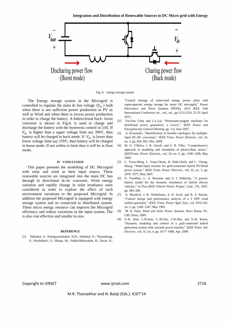
D.Energy Storage System
This study considers batteries as energy storage
devices.However, these batteries may require a dc-dc
power converterin order to step up their voltage (Vbatt )to
the main dc busvoltage (VDC )because their nominal
voltage whose level is 240V in this microgrid is typically
lower than the main dc busvoltage [6].
One reason for using a lower battery voltage is to
improvetheir reliability and life-time by avoiding issues
found in higher voltage configurations, such as cell
voltage equalization.For this purpose, a bidirectional
boost/buck converter shown in Fig. 6.is considered in
the proposed microgrid. If the powergeneration from the
renewable micro-energy sources is insufficientfor the
demand power at the load side, this bidirectional
converter operates in a boost mode in order to
discharge energyfrom batteries to the main dc bus as
depicted in Fig. 6. But,when the renewable power
production exceeds the load-sidedemand power, this
power converter works in a buck mode inwhich power
flows from the main dc bus to charge the batterieswith the
extra local power production.
Integration and Distribution of Renewable Sources in DC Micro grid with Energy
Copyright to IJIRSET www.ijirset.com 2718 M.R. Thansekhar and N. Balaji (Eds.): ICIET’14
Fig. 6: energy storage system
The Energy storage system in the Microgrid is
controlled to regulate the main dc bus voltage 𝑉𝑑𝑐 both
when there is not sufficient power production in PV as
well as Wind and when there is excess power production
in order to charge the battery. A bidirectional buck- boost
converter is shown in Fig.6. is used to charge and
discharge the battery with the hysteresis control in [10]. If
𝑉𝑑𝑐 is higher than a upper voltage limit say 390V, then
battery will be charged in buck mode. If 𝑉𝑑𝑐 is lower than
lower voltage limit say 370V, then battery will be charged
in boost mode. If not within in limit then it will be in float
mode.
IV CONCLUSION
This paper presents the modelling of DC Microgrid
with solar and wind as their input source. These
renewable sources are integrated into the main DC bus
through bi directional dc-dc converter. Wind energy
variation and rapidly change in solar irradiance were
considered in order to explore the effect of such
environment variations to the proposed Microgrid. In
addition the proposed Microgrid is equipped with energy
storage system and its connected to distributed system.
These micro energy resource can improve the Microgrid
efficiency and reduce variations in the input system. The
is also cost effective and smaller in size.
REFERENCE
[1] Sikkabut, S.; Fuengwarodsakul, N.H.; Sethakul, P.; Thounthong,
P.; Pierfederici, S.; Hinaje, M.; Nahid-Mobarakeh, B.; Davat, B.,
"Control strategy of solar/wind energy power plant with
supercapacitor energy storage for smart DC microgrid," Power
Electronics and Drive Systems (PEDS), 2013 IEEE 10th
International Conference on , vol., no., pp.1213,1218, 22-25 April
2013.
[2] Tze-Fun Chan and L.L.Lai, “Permanent-magnet machines for
distributed power generation: a review”, IEEE Power and
EnergySociety General Meeting, pp. 1-6, June 2007.
[3] A. Kwasinski, “Identification of feasible topologies for multiple-
input DC-DC converters,” IEEE Trans. Power Electron., vol. 24,
no. 3, pp. 856–861, Mar. 2009.
[4] M. G. Villalva, J. R. Gazoli, and E. R. Filho, “Comprehensive
approach to modeling and simulation of photovoltaic arrays,”
IEEETrans. Power Electron., vol. 24, no. 5, pp. 1198–1208, May
2009.
[5] C. Yaow-Ming, L. Yuan-Chuan, H. Shih-Chieh, and C. Chung-
Sheng, “Multi-input inverter for grid-connected hybrid PV/Wind
power system,” IEEE Trans. Power Electron., vol. 22, no. 3, pp.
1070–1077, May 2007.
[6] O. Tremblay, L. A. Dessaint, and A. I. Dekkiche, “A generic
battery model for the dynamic simulation of hybrid electric
vehicles,” in Proc.IEEE Vehicle Power Propul. Conf., TX, 2007,
pp. 284–289.
[7] A. Murdoch, J. R. Winkelman, S. H. Javid, and R. S. Barton,
“Control design and performance analysis of a 6 MW wind
turbine-generator,” IEEE Trans. Power Appl. Syst., vol. PAS-102,
no. 5, pp. 1340–1347, May 1983.
[8] M. R. Patel, Wind and Solar Power Systems. Boca Raton, FL:
CRC Press, 1999.
[9] S.-K. Kim, J.-H.Jeon, C.-H.Cho, J.-B.Ahn, and S.-H. Kwon,
“Dynamic modeling and control of a grid-connected hybrid
generation system with versatile power transfer,” IEEE Trans. Ind.
Electron., vol. 55, no. 4, pp. 1677–1688, Apr. 2008.