On: 16 June 2014, At: 01:13 third-party piping and drain ...repository.um.edu.my/39365/1/10589759...
12
This article was downloaded by: [University of Malaya] On: 16 June 2014, At: 01:13 Publisher: Taylor & Francis Informa Ltd Registered in England and Wales Registered Number: 1072954 Registered office: Mortimer House, 37-41 Mortimer Street, London W1T 3JH, UK Nondestructive Testing and Evaluation Publication details, including instructions for authors and subscription information: http://www.tandfonline.com/loi/gnte20 Non-destructive testing and assessment of dynamic incompatibility between third-party piping and drain valve systems: an industrial case study Keen Kuan Kong a , Siamak Noroozi b , Abdul Ghaffar Abdul Rahman c , Mihai Dupac b , Hoe Cheng Eng d , Zhi Chao Ong a , Shin Yee Khoo a & John E. Vinney b a Department of Mechanical Engineering, University of Malaya, 50603 Kuala Lumpur, Malaysia b School of Design, Engineering and Computing, Bournemouth University, Talbot Campus, Fern Barrow, Poole, Dorset BH12 5BB, UK c Mechanical Engineering Faculty, Universiti Malaysia Pahang, 26600 Pekan, Malaysia d Quadrant 2 Technologies Sdn. Bhd, Kuala Lumpur, Malaysia Published online: 16 Apr 2014. To cite this article: Keen Kuan Kong, Siamak Noroozi, Abdul Ghaffar Abdul Rahman, Mihai Dupac, Hoe Cheng Eng, Zhi Chao Ong, Shin Yee Khoo & John E. Vinney (2014) Non-destructive testing and assessment of dynamic incompatibility between third-party piping and drain valve systems: an industrial case study, Nondestructive Testing and Evaluation, 29:2, 154-163, DOI: 10.1080/10589759.2014.904313 To link to this article: http://dx.doi.org/10.1080/10589759.2014.904313 PLEASE SCROLL DOWN FOR ARTICLE Taylor & Francis makes every effort to ensure the accuracy of all the information (the “Content”) contained in the publications on our platform. However, Taylor & Francis, our agents, and our licensors make no representations or warranties whatsoever as to the accuracy, completeness, or suitability for any purpose of the Content. Any opinions and views expressed in this publication are the opinions and views of the authors, and are not the views of or endorsed by Taylor & Francis. The accuracy of the Content should not be relied upon and should be independently verified with primary sources of information. Taylor and Francis shall not be liable for any losses, actions, claims, proceedings, demands, costs, expenses, damages, and other liabilities whatsoever
-
Upload
truonghanh -
Category
Documents
-
view
214 -
download
0
Transcript of On: 16 June 2014, At: 01:13 third-party piping and drain ...repository.um.edu.my/39365/1/10589759...

This article was downloaded by: [University of Malaya]On: 16 June 2014, At: 01:13Publisher: Taylor & FrancisInforma Ltd Registered in England and Wales Registered Number: 1072954 Registeredoffice: Mortimer House, 37-41 Mortimer Street, London W1T 3JH, UK
Nondestructive Testing and EvaluationPublication details, including instructions for authors andsubscription information:http://www.tandfonline.com/loi/gnte20
Non-destructive testing and assessmentof dynamic incompatibility betweenthird-party piping and drain valvesystems: an industrial case studyKeen Kuan Konga, Siamak Noroozib, Abdul Ghaffar Abdul Rahmanc,Mihai Dupacb, Hoe Cheng Engd, Zhi Chao Onga, Shin Yee Khooa &John E. Vinneyb
a Department of Mechanical Engineering, University of Malaya,50603 Kuala Lumpur, Malaysiab School of Design, Engineering and Computing, BournemouthUniversity, Talbot Campus, Fern Barrow, Poole, Dorset BH12 5BB,UKc Mechanical Engineering Faculty, Universiti Malaysia Pahang,26600 Pekan, Malaysiad Quadrant 2 Technologies Sdn. Bhd, Kuala Lumpur, MalaysiaPublished online: 16 Apr 2014.
To cite this article: Keen Kuan Kong, Siamak Noroozi, Abdul Ghaffar Abdul Rahman, MihaiDupac, Hoe Cheng Eng, Zhi Chao Ong, Shin Yee Khoo & John E. Vinney (2014) Non-destructivetesting and assessment of dynamic incompatibility between third-party piping and drain valvesystems: an industrial case study, Nondestructive Testing and Evaluation, 29:2, 154-163, DOI:10.1080/10589759.2014.904313
To link to this article: http://dx.doi.org/10.1080/10589759.2014.904313
PLEASE SCROLL DOWN FOR ARTICLE
Taylor & Francis makes every effort to ensure the accuracy of all the information (the“Content”) contained in the publications on our platform. However, Taylor & Francis,our agents, and our licensors make no representations or warranties whatsoever as tothe accuracy, completeness, or suitability for any purpose of the Content. Any opinionsand views expressed in this publication are the opinions and views of the authors,and are not the views of or endorsed by Taylor & Francis. The accuracy of the Contentshould not be relied upon and should be independently verified with primary sourcesof information. Taylor and Francis shall not be liable for any losses, actions, claims,proceedings, demands, costs, expenses, damages, and other liabilities whatsoever

or howsoever caused arising directly or indirectly in connection with, in relation to orarising out of the use of the Content.
This article may be used for research, teaching, and private study purposes. Anysubstantial or systematic reproduction, redistribution, reselling, loan, sub-licensing,systematic supply, or distribution in any form to anyone is expressly forbidden. Terms &Conditions of access and use can be found at http://www.tandfonline.com/page/terms-and-conditions
Dow
nloa
ded
by [
Uni
vers
ity o
f M
alay
a] a
t 01:
13 1
6 Ju
ne 2
014

Non-destructive testing and assessment of dynamic incompatibilitybetween third-party piping and drain valve systems:
an industrial case study
Keen Kuan Konga, Siamak Noroozib, Abdul Ghaffar Abdul Rahmanc, Mihai Dupacb*,
Hoe Cheng Engd, Zhi Chao Onga, Shin Yee Khooa and John E. Vinneyb
aDepartment of Mechanical Engineering, University of Malaya, 50603 Kuala Lumpur, Malaysia;bSchool of Design, Engineering and Computing, Bournemouth University, Talbot Campus, FernBarrow, Poole, Dorset BH12 5BB, UK; cMechanical Engineering Faculty, Universiti MalaysiaPahang, 26600 Pekan, Malaysia; dQuadrant 2 Technologies Sdn. Bhd, Kuala Lumpur, Malaysia
(Received 17 July 2013; accepted 11 March 2014)
This paper presents the outcome of an industrial case study that involved conditionmonitoring of piping system that showed signs of excess fatigue due to flow-inducedvibration. Due to operational requirements, a novel non-destructive assessmentstratagem was adopted using different vibration analysis techniques – such asexperimental modal analysis and operating deflection shapes – and complemented byvisual inspection. Modal analysis carried out near a drain valve showed a dynamicweakness problem (several high-frequency flow-induced vibration frequency peaks),hence condition-based monitoring was used. This could easily be linked to designproblem associated with the dynamic incompatibility due to dissimilar stiffnessbetween two third-party supplied pipe and valve systems. It was concluded that this isthe main cause for these problem types especially when systems are supplied by thirdparties, but assembled locally, a major cause of dynamic incompatibility. It is the localassembler’s responsibility to develop skills and expertise needed to sustain theoperation of these plants. This paper shows the technique used as result of one suchinitiative. Since high amplitude, low-frequency displacement can cause low cyclefatigue, attention must be paid to ensure flow remains as steady state as possible. Theability to assess the level of design incompatibility and the level of modificationrequired using non-destructive testing is vital if these systems are to work continuously.
Keywords: modal analysis; non-destructive testing; ODS; pipe; stress; vibrations
1. Introduction
Vibration loading, typically mechanical or flow-induced, is the most common cause of
high cycle fatigue.[1] In a recent survey,[2] pipe cracking was identified as the most
frequently recurring problem, the most significant cause of which was determined to be
piping vibration. Mechanical vibration was one of the major causes of all reportable
occurrences involving pipes and fittings.[2] Failure of piping systems can have disastrous
effects, leading to injuries and even fatalities as well as creating a substantial additional
cost to industry and the environment. Piping vibration problems in operating plants have
resulted in costly unscheduled outages.[3] Piping vibration failures have been one of the
major causes of downtime, fires and explosions in industrial plant over the past 30 years.
For example, one piping failure at a petrochemical plant in 1974 caused over
$114,000,000 in property damage due to an explosion.[4] In nuclear pressurised water
q 2014 Taylor & Francis
*Corresponding author. Email: [email protected]
Nondestructive Testing and Evaluation, 2014
Vol. 29, No. 2, 154–163, http://dx.doi.org/10.1080/10589759.2014.904313
Dow
nloa
ded
by [
Uni
vers
ity o
f M
alay
a] a
t 01:
13 1
6 Ju
ne 2
014

reactor power plants, over 80 cases of cracks or leaks occurred in the piping systems of
charging pumps over a 2-year period.[5] Therefore, it is vitally important that piping
vibration amplitudes in a system be evaluated to determine whether the levels are
acceptable. If the vibration levels are judged to be excessive, the piping configuration,
support structure, span length or material may have to be modified to make the system
acceptable.[6–8]
Detecting, monitoring and predicting vibration [9] are important and cost-effective
ways to identify issues associated with structures such as general wear and tear, possible
imbalance problems or incompatible structural stiffness. However, vibration monitoring
can only pinpoint the root causes of failures which are usually triggered by poor design,
poor assembly, miss-alignment or imbalance of whole structure of associated components.
This incompatible structural stiffness is usually due to the presence of sub-optimal
structures that lacks dynamic compatibility due to non-uniform mass distribution or miss-
match stiffness such as fluid momentum greater than the stiffness of the pipe. In such
cases, the overall dynamic response is no longer the expected one and the system behaves
in a completely different or unpredictable manner.
One of the main causes of the unpredictable behaviour of pipes is the induced
vibrations due to the interaction between the structure (walls of the pipe as well as the pipe
supports) and the fluid flowing through the pipe. Generally, the fluid behaves as a turbulent
flow and exerts random pressures on the pipe walls.[10,11] Due to the fluid–structure
interaction including flow turbulent fluctuations and unsteady pressure on the pipe walls, a
random response will be induced to the pipe structure which may result in resonant
vibrations. The pipe response can be unstable undergoing large structural vibrations once a
critical threshold value is exceeded by the turbulent flow. It has been proved that the fluid–
structure interaction (FSI) phenomenon induces a significant response of the structure [12]
and alters the fluid force acting on the walls. The fluid-induced vibration of simply
supported and clamped pipelines was studied in [13], where parameters such as liquid
mass density to pipe-wall mass density ratio, pipe radius to pipe-wall thickness ratio, fluid
velocity and fluid pressure are considered. A vibration analysis of a three-dimensional
piping system composed of curved and straight sections is carried out in [14] using the
wave approach while the obtained results are compared with those obtained from a finite
element method (FEM) formulation.
Other causes of the unpredictable behaviour of pipes is the fluid high internal velocity
which can induce buckling on a pipe supported at both ends and high instability at on a
pipe supported at one end. A structured and systematic assessment approach of the
vibration of pipes was considered in [15], The study conveys that some of main problems
in the existing vibrating piping systems are due to poor supporting systems.
The general stability problem of vibrating pipes conveying fluid has been studied
extensively in [10,11,16], The nonlinear dynamics of a pulsatile pipe conveying fluid was
studied in [17] while the nonlinear dynamics of a curved pipe conveying fluid subject
harmonic excitation was studied in [18].
The phase-shift effects of resonant vibrating pipes due to various imperfections are
discussed in [19,20] and their dynamic structural response in [21]. The perturbation
analysis used provides direct insight into how the non-uniform mass, stiffness, the non-
proportional damping or weak imperfections affect the phase shift. The post-buckling
effect in vibrating pipes which permit axial sliding and do not deflect transversely was
discussed in [22]. Traditionally, modal parameters, such as that presented above, are
extracted by conducting experimental modal analysis (EMA) on a static pipe structure.
However sometimes extracting modal parameters while the system is in operation is
Nondestructive Testing and Evaluation 155
Dow
nloa
ded
by [
Uni
vers
ity o
f M
alay
a] a
t 01:
13 1
6 Ju
ne 2
014

highly desirable. A method named operational modal analysis (OMA) has been introduced
in order analyse structures subjected to excitation generated by their own operation.[23]
System identification methods are efficient OMA tools to estimate modal parameters from
ambient vibrations. A review of in operation identification for modal analysis that is
stochastic system identification (SSI) has been fully reviewed in [24]. The method
described in [25] was successfully used to identify damages during the operation of the
pipes of a gas compressor due to operating equipment as well as the flowing fluid. When
classical condition monitoring is not possible, in-service operating deflection shape
(ODS), a non-invasive and non-destructive approach to monitor and visualise the motion
of the system while in operation,[26–31] can be successfully used.
To assess possible structural damage, fatigue crack initiation, growth behaviour and
resistance of cracked pipes under cyclic loading have been studied in [32]. A failure
analysis of a hydraulic pipe due to resonance condition as a form of energy dissipation
resulting from viscous friction has been presented in [33], where a crack structural damage
was assessed due to the corrosion of the pipe and the reach of maximal admissible stress.
A failure analysis of a natural gas pipe adjacent to a source of vibration, based on pipe
material characterisation, dynamic stress, modal analysis and metallurgical assessment,
was studied in [34]. The main factor leading to failure (a crack was initiated) was
considered the huge energy level due to an increase in the amplitude of a vibrating valve
leading to the development of the pipe dynamic stress.
This paper presents the outcome of an industrial case study that involved condition
monitoring of a piping system that showed signs of excess fatigue due to flow-induced
vibration. Due to operational requirement, a novel non-destructive assessment stratagem
was adopted using different vibration analysis techniques – such as EMA and ODS – and
complemented by visual inspection. Modal analysis carried out near a drain valve showed
a dynamic weakness problem (several high-frequency flow-induced vibration frequency
peaks), hence initiated condition-based monitoring. The analysis reveals a dynamic
weakness problem of a drain valve along the piping system, due to a design problem and
dynamic incompatibility of the supplied pipe and valve systems. This could easily be
linked to design problem associated with the dynamic incompatibility due to dissimilar
stiffness between two third-party supplied pipe and valve systems. It was concluded that
this is the main cause for these types of problem especially when systems are supplied by
third parties and assembled locally.
2. Problem formulation
Condition monitoring of an industrial piping system shown in Figure 1 is considered in this
section. Due to the operational requirements, a non-destructive assessment stratagem to
carry out a vibration diagnostic and analysis was considered using the EMA and the ODSs
analysis techniques described in the following sections.
The non-destructive technique is based on a measurement procedure and vibration
criteria to evaluate whether or not the high recorded vibrations of the industrial piping
system introduced highly vibratory stress into the piping by its running conditions.
2.1 EMA and ODSs analysis
EMA: It is an investigation on vibration characteristics of elastic structures. EMA requires
the system to be in a complete ‘shutdown’ state, which means no unaccounted excitation
force induced into the system. Measurable impacts or random forces are used to excite the
K.K. Kong et al.156
Dow
nloa
ded
by [
Uni
vers
ity o
f M
alay
a] a
t 01:
13 1
6 Ju
ne 2
014

system. The responses of the system are cross-correlated with the measured inputs. Transfer
functions are later obtained by considering the Fourier transform of the cross-correlated
functions. This procedure is repeated with a discrete set of geometrical positions which are
sufficient todescribe the structure.Various curve-fitting algorithmsare thenused to extract the
three parameters: namely, natural frequencies, mode shapes and modal damping.
EMAwith single-input single-output (SISO), single-input multiple-output (SIMO) and
multiple-input multiple-output (MIMO) modal identification algorithms in time,
frequency and spatial domain has been widely used in troubleshooting, structural
dynamic modification, analytical model updating, optimal dynamic design, passive and
active vibration control, as well as vibration-based structural health monitoring in
aerospace, mechanical and civil engineering. In applications, the extracted modal
parameters from EMA have been widely used to detect damage on beams and beam-like
structures [35–39] as well as rotor systems.[40,41] These are the methods used for damage
detection based on dynamic characteristics of structures such as natural frequencies,
dynamic mode shapes and structural damping. These methods have taken advantage of the
present-day development of modal analysis techniques with accurate measurements of
modal parameters. When damage event occurs, the structural dynamic characteristics
changes and this may be used as an indicator of damage.
ODSs analysis: A very attractive solution named ODS can measure the deflection of
structures while in-service. Generally, an ODS can be defined as ‘any forced motion of two
or more points on a structure’ [26] and can be planar, orbital or three dimensional. As ODS
represents a linear combination of the mode shapes of a structure, ODS measurement
should be carried out under constant and stable operating conditions in order to obtain
accurate results. The measurement should be carried out in such a way so that the
measurement equipment does not affect the answer of the system, that is, a high signal-to-
noise ratio. In the measurement process, the constant and stable operating condition
depends on the system complexity and whether all degrees of freedom (DOF) are
measured simultaneously, while the ‘simultaneous’ condition depends on the number of
data acquisition channels and DOFs to be measured.
There are basically three types of ODS, named Time ODS which measure measures
the vibration of a structure as a function of time, or Spectral ODS and Run-up/down ODS
Figure 1. Industrial piping system.
Nondestructive Testing and Evaluation 157
Dow
nloa
ded
by [
Uni
vers
ity o
f M
alay
a] a
t 01:
13 1
6 Ju
ne 2
014
which measure the vibration pattern of an equipment (typically a rotating machinery) at a
discrete operating frequency. For a pipe operating structure when no rotating equipment is
used along the pipe, the measured time signal obtained from the ODS can be processed to
show the pipe behaviour over time.
2.2 Measurement procedure description
A non-invasive measurement and evaluation procedure applied to a piping system
that showed signs of excess fatigue was considered based on the ‘need to know’ whether
and how the stress induced into the piping by its running conditions, i.e. flow-induced
high-amplitude vibrations, affect the overall structural integrity of the piping system.
The measurement and evaluation procedure have been devised using a state-of-the-art
MDT-Q2 data acquisition system (Quadrant & Technologies SDN. BHD.) based on a 4-
channel real-time machinery analyser, tri-axial (measurement locations were taken in the
principal directions) and uni-axis accelerometers, modally tuned impact hammer and
related equipment and ME’scope software (Vibrant Technology, Inc., USA) used to
analyse the motion and the excessive vibration levels of the piping system. It has been
observed that the flow-induced vibrations may not cause excessive stresses in the main
pipe but to the adjacent systems that are attached to the vibrating pipe.
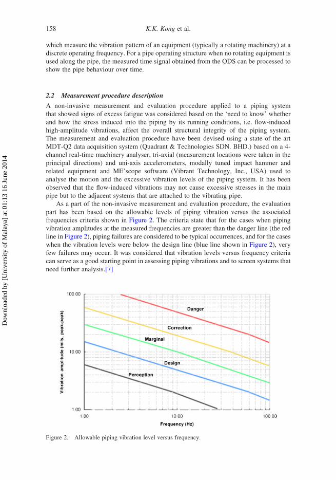
As a part of the non-invasive measurement and evaluation procedure, the evaluation
part has been based on the allowable levels of piping vibration versus the associated
frequencies criteria shown in Figure 2. The criteria state that for the cases when piping
vibration amplitudes at the measured frequencies are greater than the danger line (the red
line in Figure 2), piping failures are considered to be typical occurrences, and for the cases
when the vibration levels were below the design line (blue line shown in Figure 2), very
few failures may occur. It was considered that vibration levels versus frequency criteria
can serve as a good starting point in assessing piping vibrations and to screen systems that
need further analysis.[7]
Figure 2. Allowable piping vibration level versus frequency.
K.K. Kong et al.158
Dow
nloa
ded
by [
Uni
vers
ity o
f M
alay
a] a
t 01:
13 1
6 Ju
ne 2
014

3. Results
Modal analysis was carried out during non-operating condition to obtain the natural
frequencies of industrial piping system and structure. Figure 3 shows the results for
different locations.
Modal analysis carried out on the structure does not show any peak at the flow-induced
frequencies region (5–15Hz). All the vibration measurements on the structure are low
compared to the vibration level of the pipe indicating no structural dynamics weakness.
This indicates that there is no structural dynamics weakness issue of the structure.
The pipe dynamics weakness situation was assessed along the pipe. The detailed
locations are described as follows: modal analysis along the pipes shows some natural
frequencies at 5–15Hz region which might indicate the pipe dynamics weakness for six
locations named L1, L2, . . . , L6. Cracks have been observed at the connections L3, L5 and
L6 (between the drain valve and main pipe) and high vibrations were recorded at those
locations. It was also observed that the vibration level increases when increasing the flow
rate. As cyclic excitation (and not random vibration) generates resonance situation, it was
supposed that the high vibration of the pipe was probably due to flow-induced excitation
which is a stiffness-controlled situation rather than a pipe dynamics weakness. As a result,
it was concluded that the high vibration of the pipe is probably due to the process and
design problem.
The evaluation of whether or not the high vibration levels represent a problem has to be
based primarily on the vibratory stresses introduced into the piping. Many times,
apparently high vibration may not cause excessive stresses in the piping, but could cause
excessive stresses to piping system that is attached to the vibrating pipe. As cracks were
found at the connection between the drain valve and main pipe, vibration measurements
have been carried out on the kicker line drain valve shown in Figure 4(a) in order to assess
the vibration levels. The recorded vibrations for kicker line drain valve are shown in
Figure 4(b) with the high vibration level dominant frequency at 47Hz in x-axis caused
mainly by the unsuitable design or selection of the drain valve.
In order to observe whether there is any excessive stress in the piping caused by the
valve, the effect of the valve on the vibrations levels by vibration measurement was
Figure 3. Modal analysis on locations L1–L6 are ahown in (a)–(f).
Nondestructive Testing and Evaluation 159
Dow
nloa
ded
by [
Uni
vers
ity o
f M
alay
a] a
t 01:
13 1
6 Ju
ne 2
014

analysed after removing the valve as shown in Figure 5(a). It can be observed that the 47-
Hz frequency component has been eliminated as shown in Figure 5(b).
The cracks in kicker drain valve have proved that the improper design and unsuitable
drain valve location affect the piping system. In this case, the designed drain valves are too
long and heavy; therefore, fatigue failure is easily to occur for this kind of design. To
evaluate the vibration of the pipe due to operation condition and the risk of apparently high
vibration which may induce excessive stress to piping system that are attached to the
vibrating pipe, an ODS analysis have been carried out for different testing conditions
(decided based on the pipe operating conditions) as shown in Figure 6.
In Figures 2 and 6, we can observe that the vibration amplitudes of the pipe at the
measured frequencies do not overlay the danger line and therefore no failures of the pipe
are expected. However, two vibration tests carried out at a maximal flow rate
(350mmscfd) show highest vibration levels for the pipe and a possible contribution in
increasing the levels of stress to piping system that are attached to the vibrating pipe,
especially when, as resulting from the modal analyses, these systems which are supplied
by third parties and assembled locally suffer from dynamic incompatibility. Therefore,
Figure 4. Before modification: (a) kicker line drain valve and (b) valve vibration level versusfrequency.
Figure 5. After modification: (a) kicker line drain valve and (b) valve vibration level versusfrequency.
K.K. Kong et al.160
Dow
nloa
ded
by [
Uni
vers
ity o
f M
alay
a] a
t 01:
13 1
6 Ju
ne 2
014

these vibrations versus frequency criteria can serve as a good starting point in evaluating
piping vibrations in screening those systems that need further analysis.
4. Conclusions
In this paper, an investigation into the application of non-destructive evaluation of in-
service pipe has been presented. The modal analyses applied to the piping structure do not
Figure 6. ODS analysis for the pipe for different testing conditions.
Nondestructive Testing and Evaluation 161
Dow
nloa
ded
by [
Uni
vers
ity o
f M
alay
a] a
t 01:
13 1
6 Ju
ne 2
014

show any indication of a structural dynamics weakness issue. Modal analysis along the
pipes shows that there are few natural frequencies at 5–15Hz region which may be an
indication of the pipe dynamics weakness. Some of the modal analyses which have been
carried out near a drain valve showed a design problem due to dissimilar stiffness –
dynamic incompatibility – between the supplied pipe and valve systems.
It was concluded that this was the main cause for these types of problem especially
when these systems are supplied by third parties, but assembled locally. Moreover, since
the high vibration response of the pipe was mainly due to the flow-induced excitation as
shown by the ODS analysis, a combined further analysis on the pipe design and flow
(including a dynamical stress analysis and FSI) is needed in order to (a) understand the
process flow inside the pipe, (b) understand the flow-induced vibration/stresses for the
entire system, (c) optimise piping production and (d) run the system under allowable
endurance stress limit and safe condition.
References
[1] Agency ONE. Nuclear power plant operating experiences from the IAEA/NEA incidentreporting system. 2002–2005. p. 1–56. France: OECD Publication; 2006.
[2] Rao KR, David E Olson. Companion Guide to the ASME boiler and pressure vessel code,Volume 2, Third Edition, Pipe vibration testing and analysis 2009; 10.1115/1.802700.ch37.
[3] Olson DE. Pipe vibration testing and analysis. Companion guide to the ASME boiler &pressure vessel code (Vol. Chapter 37). New York, NY: ASME; 2002.
[4] Garison WG. Major fires and explosions analyzed for 30-year period, Hydrocarbon Process.1988;67:115–120.
[5] Olson DE. Piping vibration experience in power plants, pressure vessel and piping technology,a decade of progress. Book No. H0030. New York: ASME; 1985.
[6] Wachel JC, Morton SJ, Atkins KE. Piping vibration analysis. 19th TurbomachinerySymposium; 1990 Sep; Texas A&M University.
[7] Wachel JC. Piping vibration and stress, vibration institute, machinery vibration monitoring andanalysis seminar; 1981 Apr; New Orleans, LA. p. 1–20.
[8] Wachel JC. Displacement method for determining acceptable piping vibration amplitudes,PVP-Vol. 313-2. Vol. 2, International pressure vessels and piping codes and standards. NewYork: ASME; 1995.
[9] Rao SS. Mechanical vibration. SI ed. London: Prentice Hall; 2005.[10] Blevins RD. Flow induced vibration. 2nd ed. New York, NY: Van Nostrand Reinhold; 1990.[11] Chen SS. Flow-induced vibration of circular cylindrical structures. Washington, DC:
Hemisphere Publishing Corporation; 1987.[12] Dai HL, Wang L, Qian Q, Gan J. Vibration analysis of three-dimensional pipes conveying fluid
with consideration of steady combined force by transfer matrix method, Appl Math Comput.2012;219:2453–2464.
[13] Zou GP, Cheraghi N, Taheri F. Fluid-induced vibration of composite natural gas pipelines. IntJ Solids Struct. 2005;42:1253–1268.
[14] Koo GH, Park YS. Vibration analysis of a 3-dimensional piping system conveying fluid bywave approach. Int J Pres Ves Pip. 1996;67:249–256.
[15] Sukaih N. A practical, systematic and structured approach to piping vibration assessment. IntJ Pres Ves Pip. 2002;79:597–609.
[16] Chen SS. Flow-induced vibration of circular cylindrical structures. Washington, DC:Hemisphere Publishing Corporation; 1987.
[17] Panda LN, Kar RC. Nonlinear dynamics of a pipe conveying pulsating fluid with combination,principal parametric and internal resonances. J Sound Vib. 2008;309:375–406.
[18] Lin W, Qiao N, Yuying H. Dynamical behaviours of a fluid-conveying curved pipe subjected tomotion constraints and harmonic excitation. J Sound Vib. 2007;306:955–967.
[19] Enz S, Thomsen JJ. Predicting phase shift effects for vibrating fluid-conveying pipes due toCoriolis forces and fluid pulsation. J Sound Vib. 2011;330:5096–5113.
[20] Thomsen JJ, Dahl J. Analytical predictions for vibration phase shifts along fluid-conveyingpipes due to Coriolis forces and imperfections. J Sound Vib. 2010;329:3065–3081.
K.K. Kong et al.162
Dow
nloa
ded
by [
Uni
vers
ity o
f M
alay
a] a
t 01:
13 1
6 Ju
ne 2
014

[21] Semke WH, Bibel GD, Jerath S, Gurav SB, Webster AL. Efficient dynamic structural responsemodelling of bolted flange piping systems. Int J Pres Ves Pip. 2006;83:767–776.
[22] Plaut RH. Postbuckling and vibration of end-supported elastica pipes conveying fluid andcolumns under follower loads. J Sound Vib. 2006;289:264–277.
[23] Mohanty P, Rixen DJ. A modified Ibrahim time domain algorithm for operational modalanalysis including harmonic excitation. J Sound Vib. 2004;275(1–2):375–390.
[24] Peeters B, De Roeck G. Stochastic system identification for operational modal analysis: areview. J Dyn Syst Meas Control. 2001;123(4):659–667.
[25] Trebuna F, Simcak F, Hunady R, Pastor M. Identification of pipes damages on gas compressorstations by modal analysis methods. Eng Fail Anal. 2013;27:213–224.
[26] Devriendt C, Steenackers G, DeSitter G, Guillaume P. From operating deflection shapestowards mode shapes using transmissibility measurements. Mech Syst Signal Process.2010;24:665–677.
[27] Dossing O, Staker CH. Operational deflection shapes: background. measurement andapplications. Proceedings of the 5th International Modal Analysis Conference; 1987 April 6-9;London, Imperial College of Science & Technology (UK): Union College, Graduate andContinuing Studies; 1987.
[28] Marscher WD, Jen CW. Use of operating deflection and mode shapes for machinerydiagnostics. Proc. SPIE Vol. 3727, Bethel, CT, USA. Proceedings of the 17th InternationalModal Analysis Conference; 1999; Florida (USA).
[29] McHargue PL, Richardson MH. Operating detection shapes from time versus frequencydomain measurements. IMAC-XI The 11th International Modal Analysis Conference andExposition; 1993; Florida (USA): SEM Proceedings, Bethel, CT, USA, 1993.
[30] Pascual R, Golinval JC, Razeto M. On-line damage assessment using operating detectionshapes. In: Wicks, AL, DeMichele, DJ Proceedings of 17th International Modal AnalysisConference; 1999 February 8–11; Florida: Society of Photo-optical InstrumentationEngineers, Society for Experimental Mechanics (U.S.) 1999.
[31] Tongue BH. Principles of vibration. 2nd ed. Oxford: Oxford University Press; 2002.[32] Singha PK, Vazea KK, Bhasina V, Kushwahaa HS, Gandhib P, Ramachandra Murthy DS.
Crack initiation and growth behaviour of circumferentially cracked pipes under cyclic andmonotonic loading. Int J Pres Ves Pip. 2003;80:629–640.
[33] Rouabeh K, Schmitt C, Elaoud S, Hadj-Taıeb E, Pluvinage G. Failure of grey cast iron waterpipe due to resonance phenomenon. Eng Fail Anal. 2012;26:120–128.
[34] Ashrafizadeh H, Karimi M, Ashrafizadeh F. Failure analysis of a high pressure natural gas pipeunder split tee by computer simulations and metallurgical assessment. Eng Fail Anal.2013;32:188–201.
[35] Fayyadh MM, Razak HA, Ismail Z. Combined modal parameters-based index for damageidentification in a beamlike structure: theoretical development and verification. Arch CivilMech Eng. 2011;11:587–609.
[36] Ismail Z, Ong ZC. Honeycomb damage detection in a reinforced concrete beam usingfrequency mode shape regression. Measurement. 2012;45:950–959.
[37] Ismail Z. Application of residuals from regression of experimental mode shapes to locatemultiple crack damage in a simply supported reinforced concrete beam. Measurement. 2012;45(6):1455–1461.
[38] Ismail Z, Ibrahim Z, Ong AZC, Rahman AGA. Approach to reduce the limitations of modalidentification in damage detection using limited field data for nondestructive structural healthmonitoring of a cable-stayed concrete bridge. J Bridge Eng. 2012;17(6):867–875.
[39] Dilena M, Morassi A. Experimental modal analysis of steel concrete composite beams withpartially damaged connection. J Vib Control. 2004;10(6):897–913.
[40] Ong ZC, Rahman AGA, Ismail Z. Determination of damage severity on rotor shaft due to crackusing damage index derived from experimental modal data, Exp Techniques. Forthcoming2012.
[41] Rahman AGA, Ismail Z, Noroozi S, Ong ZC. Study of open crack in rotor shaft using changesin phase of frequency response function (FRF). Int J Damage Mech. 2013;22:791–807.
Nondestructive Testing and Evaluation 163
Dow
nloa
ded
by [
Uni
vers
ity o
f M
alay
a] a
t 01:
13 1
6 Ju
ne 2
014