OmegaCAM OmegaCAM Data Flow System - CALIBRATION … · CAP sections updated to re°ect the use of...
101
NOVA - Kapteyn Institute USM – OaPd OmegaCAM CalPlan ID VST-PLA-OCM-23100-3090 Issue Version 2.2 Date 13 Apr 2006 Page 1 OmegaCAM OmegaCAM Data Flow System - CALIBRATION PLAN Implementation of Calibration Requirements Issue: Version 2.2 Date: 13 Apr 2006 Prepared by: Valentijn, Begeman, Boxhoorn, Deul, Rengelink , Vermey Purpose of printout: TEMPLATE NAME UPDATE Approved by: Konrad Kuijken, OmegaCAM PI. Edwin Valentijn, NOVA programme manager. www.astro.rug.nl/∼omegacam This document is prepared by the Odoco Document Control System.
Transcript of OmegaCAM OmegaCAM Data Flow System - CALIBRATION … · CAP sections updated to re°ect the use of...

NOVA - Kapteyn Institute
USM – OaPd
OmegaCAM
CalPlan
ID VST-PLA-OCM-23100-3090
Issue Version 2.2
Date 13 Apr 2006
Page 1
OmegaCAM
OmegaCAM Data Flow System - CALIBRATION PLANImplementation of Calibration Requirements
Issue: Version 2.2
Date: 13 Apr 2006
Prepared by: Valentijn, Begeman, Boxhoorn, Deul, Rengelink , Vermey
Purpose of printout: TEMPLATE NAME UPDATE
Approved by:
Konrad Kuijken, OmegaCAM PI.
Edwin Valentijn, NOVA programme manager.
www.astro.rug.nl/∼omegacam
This document is prepared by the Odoco Document Control System.

NOVA - Kapteyn Institute
USM – OaPd
OmegaCAM
CalPlan
ID VST-PLA-OCM-23100-3090
Issue Version 2.2
Date 13 Apr 2006
Page 2
Version 1.0 has been delivered at the FDR. Following comments at FDR version 1.1 has beenprepared, which has been approved by FDR board.
Thus version 1.1 is the FDR formal version.
Changes between Version 1.0–FINAL DESIGN REVIEW and Version 1.1–FINAL DESIGN RE-VIEW
AdditionsNew section on 2-3 day cycle specifications – 2.2 DFS requirements.Specify all three levels of TSF’s, as given in VST-SPE-OCM-23100-3064, in requirements.Detailed estimates of observing times for photometric checks – 2.2 DFS requirements,req.562, req.563, req.564.Include tilt determination – req. 571 Camera focus/tilt.CalFile– 562S Sky brightness – req.562.Reference to req.563 in CA – req.564.OmegaCAM DID – 1.2 Applicable documents.Once/year dark dome test – req.533.Processing of calibration data follows telescope schedule – 2.2 DFS requirements, 6.1 Datareduction software requirements. Expanded the glossary with all term used in the docu-ment.
UpdatesClarify fast recipe for Technical Specifications conformance – req.562, req.563.Erroneous references to darkcurrent check for req. 547 Quick detector responsivity checkremoved.Nonexistent CalFile– 561 removed – req.533.Stars have to be observed during the night – req.525.req. 571 Camera focus/tilt is no longer a workhorse/doit – 1.4 Abbreviations andAcronyms, 5.10 On site quick look analysis.Exposure times TBC during commissioning – req.561.More accurate description of the algorithm – req.523.Lamp procedure TBC. – 5.4 Detectors operational specific calibrations.Removed reference to QCO – seq.– 631.Mention acceptance of multi-extension FITS files – seq.– 631.Target-related template parameters (only) where applicable – 4.4 Observing Templates.Reworded sentence about DFS-pipeline – 5.10 On site quick look analysis.Reworded sentence about modules – 6.1 Data reduction software requirements.Rotator offset angle – 4.4 Observing Templates.Use plots for analysis – req. 571 Camera focus/tilt.Rephrased in terms of provided functionality instead of needed functionality – 7 FUNC-TIONALITIES.

NOVA - Kapteyn Institute
USM – OaPd
OmegaCAM
CalPlan
ID VST-PLA-OCM-23100-3090
Issue Version 2.2
Date 13 Apr 2006
Page 3
Changes between Version 1.1–FINAL DESIGN REVIEW and Version 2.0–PAE
Major changes since FDR- settling the key bands u’,g’,r’ and i’ and filter sets
Minor changes since FDR- req 534, 535 - uses r’filter- req 562 - Calfile 562S is split up in its separate photometric bands- req 569 - Calfile 569 secondary standards, internal now- req 561 - Emphasize two shutter directions
AdditionsCalFile– 548F Illumination correction fit coefficients – req.548.CalFile– 562Su Sky brightness-u’ ,CalFile– 562Sg Sky brightness-g’ ,CalFile– 562Sr Sky brightness-r’ ,CalFile– 562Si Sky brightness-i’ – req.562.Cross-calibration of composite vs. monolithic key filters CalFile– 565C composite ->monolithic – req.565.Recipe– PhotCal Monitoring Sky for on-line sky spectrum measurement – req.562.INT-La Palma preparatory programme for one square degree secondary standard fields .Added Appendix A6: sky grid of pointing positions, also used for pixel grid in co-addition
UpdatesThe composite filter is created by a different company from the one that created themonolithic filters – req.565.Alternative analysis method for CCD Charge Transfer Efficiency – req.534.CalFile– 533 replaced by CalFile– 533P CCD Linearity Plot , CalFile– 533M CCDLinearity map – req.533.CalFile– 563Z,I renamed CalFile– 563– req.563.Further specifications of focus/tilt analysis – req.571.
RemovedCalFile– 546W Weightmap – req.546.On-site on sky health check monitoring using standard fields. This activity, thoughemphasized at FDR by ESO, was removed on request of ESO. req. 562 Monitoring.
Following these changes CP Version 2.0 has been prepared for PAE.

NOVA - Kapteyn Institute
USM – OaPd
OmegaCAM
CalPlan
ID VST-PLA-OCM-23100-3090
Issue Version 2.2
Date 13 Apr 2006
Page 4
Changes between Version 2.0–PAE and Version 2.1–PAE
AdditionsCalibration Verification Matrix added as Appendix A7.Figure 3a containing only parts of the data model relevant to ESO-DFS – section 3.The command-line syntax for each Recipe. Clarify which parameters are mandatory andwhich are optional.A complete description of each parameter of a Recipe.Valid values or a range of valid values for each parameter of a Recipe.Check reproducibility of filter exchange mechanism – req. 542 Flat-field - dome keybands + user bands - doit.Typical exposure time added – req. 543 Flat-field - twilight.Telescope should be tracking – req. 543 Flat-field - twilight.Jittered observation should be used to remove stars – req. 543 Flat-field - twilight.In each req. where stacking is used, explained why and how this is done.Recipe– Illumination Correction Verify in req. 548 Illumination correction Fully au-tomated recipe to determine illumination correction- description of procedure and recipe.Recipe– PhotCal Monitoring Sky used in req. 562 Photometric Calibration - moni-toring .Recipe– PhotCal Extract Resulttable used in req.562, req.563 and req.564.Documentation for CAT III recipes - req. 554 PSF anisotropy req. 562 Photometricmonitoring- Sky Brightness monitoring req. 548 Illumination correction- Quick veri-ficationA description of the reference hardware used for processing has been given.Suggested QC parameters in CAP section.Output plot for Recipe– PSF Anisotropy included – req. 554 PSF Anisotropy.
UpdatesMade names of calfiles in all figures consistent with the nomenclature used in the require-ments.Consistently used the “master” prefix in CalFile– name throughout the documentation.Read noise value and gain are single numbers in the ESO context, not CalFile– ’s .Clarified illumination correction procedure – req. 548 Illumination Correction.Use ADU in output units – req. 521 CCD read noise - doit, req. 532 CCD ParticleEvent Rate.TSF section did not refer to read noise template – req. 532 CCD Particle Event Rate.Changed default values for cold pixel threshold in the text – req. 535 CCD Cold Pixels.Mention astrometric pre-solution procedure to determine approximate pixel scale and po-sition of reference pixel – req. 551 Position of Camera in focal plane.Detailed clarification of the objective – req.553Telescope and Field Rotator tracking.In req.562, req.563 and req.564 catalogue derivation and processing of catalogues have

NOVA - Kapteyn Institute
USM – OaPd
OmegaCAM
CalPlan
ID VST-PLA-OCM-23100-3090
Issue Version 2.2
Date 13 Apr 2006
Page 5
been separated, resulting in a new dataflow. The text of the requirements, the figures,analysis descriptions and data reduction procedures have been updated accordingly.CalFile– 562u, CalFile– 562g, CalFile– 562r, CalFile– 562i replaced by genericCalFile– 562T Photom + Sky.Full re-write of data reduction using MIDAS procedure – req.571.Perform regridding without co-addition in Recipe– Stare in seq.– 632.Ordered requirement sections by requirement number, rather than by category.Made each requirement start at the top of a page.Processing times updated following measurements with the specified reference hardware.CAP sections updated to reflect the use of Recipe parameters.Replaced references to “image pipeline” to “image part of the pipeline”.Changed the order of items in each requirement.Grid on the sky has been fine-tuned – Appendix A6.
RemovedText related to automatic trend-analysis and verification of pipeline products in all re-quirements.Text suggesting that reminiscence can be removed by CCD read out – req. 536 CCDHysteresis, strong signal.Text about reminiscence short than 60 seconds – req. 536 CCD Hysteresis, strong signal.
Following these changes CP Version 2.1 has been prepared for PAE.

NOVA - Kapteyn Institute
USM – OaPd
OmegaCAM
CalPlan
ID VST-PLA-OCM-23100-3090
Issue Version 2.2
Date 13 Apr 2006
Page 6
Changes between Version 2.1–PAE and Version 2.11–PAE
AdditionsIncluded mandatory raw domeflats in inputs section – req. 523 CCD gain.Note added about cold restart of FIERA – req. 541 Bias - doit.Copied over number of stars for photometric accuracy, magnitude accuracy and re-sponse to SExtractor automatic aperture concerns from Photometric progress report –req. 562 Photometric Calibration - monitoring, req. 569 Secondary Standards.Values included for SExtractor, LDAC and Swarp configuration parameters if they differfrom the defaults for each of these packages – req.531, seq.– 632, seq.– 633, seq.–634, seq.– 636.
UpdatesRenamed Recipe– Stare to Recipe– Reduce and renamed Recipe– Dither to Recipe–Coadd because they do not correspond to Mode– Stare N= and Mode– Dither N= re-spectively – 6 DATA REDUCTION SOFTWARE SPECIFICS.Corrected units of particle event rate – req. 531 CCD Dark Current - doit, req. 532 CCDParticle Event Rate.Some CCD’s will have worse CTE than the required accuracy – req. 534 CCD ChargeTransfer Efficiency.Made roles of optical axis and the mechanical rotator axis more clear – req. 551 Positionof Camera in focal plane.Text about use of guide stars for pointing tests made more explicit – req. 552 Telescopeand Field Rotator tracking.Explained role of the ADC in the text – req. 566 Dependency on angle - ADC, rota-tor/reproducibility.Clarified that regridding takes place in Recipe– Reduce for observations done in Mode–Stare – 6.3 The Image Pipeline, seq. 632 Trim, de-bias, flatfield, seq. 636 Dedither-ing/dejittering.Corrected titles of seq.– 633 and seq.– 634 to reflect that the seeing is determined inseq.– 634.Rephrased and removed references to trend-analysis – 2 Manual, Modules, Recipes.
RemovedReferences to Paranal and QC1 removed from figure 3b – 3 Data Flow.
Following these changes CP Version 2.11 has been prepared for PAE.

NOVA - Kapteyn Institute
USM – OaPd
OmegaCAM
CalPlan
ID VST-PLA-OCM-23100-3090
Issue Version 2.2
Date 13 Apr 2006
Page 7
Changes between Version 2.11–PAE and Version 2.2–Template Name Update
AdditionsAppendix ”TSFs and DPR keys” detailing changes to templates.
UpdatesChanges regarding template name updates:
Names of templates starting with OCM ... are renamed to OCAM ... to be consis-tent with the Instrument Software Template Manual.In req. 534 CCD Charge Transfer Efficiency: Template OCAM img cal cte is with-drawnIn req. 562 Photometric Calibration - monitoring: Template OCAM img obs monit re-named to OCAM img cal monit.In req. 563 Photometric Calibration - zeropoint keybands: Template OCAM img obs zpkeyrenamed to OCAM img cal zp.In req. 564 Photometric Calibration - zeropoint user bands: Template OCAM img obs zpuserrenamed to OCAM img cal zp.In section 4 where applicable: template name changes as in above.
Other changes:
In req. 522 Hot pixels: The pseudo-code was improved to handle induced charge struc-tures.In req. 523 CCD Gain: An error in the pseudo-code was fixed.In req. 544 Flat-field: night sky: An error in the pseudo-code was fixed.In req. 547 Quick detector responsivity check: The inputs and pseudo-code of Recipe–Quick Check have changed.
Following these changes CP Version 2.2 has been prepared for Template Name Update.

NOVA - Kapteyn Institute
USM – OaPd
OmegaCAM
CalPlan
ID VST-PLA-OCM-23100-3090
Issue Version 2.2
Date 13 Apr 2006
Page 8
TABLE of CONTENTS
1 INTRODUCTION . . . . . . . . . . . . . . . . . . . . . . . . . . . . . . . . . . . . . . . . . . . . . . . . . . . . . . . . . . . . . . . . . . . 111.1 Context . . . . . . . . . . . . . . . . . . . . . . . . . . . . . . . . . . . . . . . . . . . . . . . . . . . . . . . . . . . . . . . . . . . . . . . . .111.2 Applicable documents . . . . . . . . . . . . . . . . . . . . . . . . . . . . . . . . . . . . . . . . . . . . . . . . . . . . . . . . . . . 111.3 Reference documents . . . . . . . . . . . . . . . . . . . . . . . . . . . . . . . . . . . . . . . . . . . . . . . . . . . . . . . . . . . . 111.4 Abbreviations and Acronyms . . . . . . . . . . . . . . . . . . . . . . . . . . . . . . . . . . . . . . . . . . . . . . . . . . . . . 12
2 SCIENTIFIC REQUIREMENTS -see URD . . . . . . . . . . . . . . . . . . . . . . . . . . . . . . . . . . . . . . . . . . . . 143 INSTRUMENT CONCEPT- Summary -see URD . . . . . . . . . . . . . . . . . . . . . . . . . . . . . . . . . . . . . . 144 OBSERVING MODES and STRATEGIES -see URD . . . . . . . . . . . . . . . . . . . . . . . . . . . . . . . . . . 14
4.4 Observing Templates . . . . . . . . . . . . . . . . . . . . . . . . . . . . . . . . . . . . . . . . . . . . . . . . . . . . . . . . . . . . 145 BASELINE CALIBRATION REQUIREMENTS . . . . . . . . . . . . . . . . . . . . . . . . . . . . . . . . . . . . . . . . 16
5.0 Documentation system, Odoco . . . . . . . . . . . . . . . . . . . . . . . . . . . . . . . . . . . . . . . . . . . . . . . . . . . 165.1 Functional Checks . . . . . . . . . . . . . . . . . . . . . . . . . . . . . . . . . . . . . . . . . . . . . . . . . . . . . . . . . . . . . . .225.2 Detector Electronics specific Calibrations . . . . . . . . . . . . . . . . . . . . . . . . . . . . . . . . . . . . . . . . . 22
5.2.1 Req.– CCD read noise - doit . . . . . . . . . . . . . . . . . . . . . . . . . . . . . . . . . . . . . . . . . . . . . . 225.2.2 Req.– hot pixels . . . . . . . . . . . . . . . . . . . . . . . . . . . . . . . . . . . . . . . . . . . . . . . . . . . . . . . . . . . 235.2.3 Req.– CCD gain . . . . . . . . . . . . . . . . . . . . . . . . . . . . . . . . . . . . . . . . . . . . . . . . . . . . . . . . . . 245.2.4 Req.– Electromagnetic Compatibility . . . . . . . . . . . . . . . . . . . . . . . . . . . . . . . . . . . . . . . 255.2.5 Req.– Electrical cross talk . . . . . . . . . . . . . . . . . . . . . . . . . . . . . . . . . . . . . . . . . . . . . . . . . 26
5.3 Detectors specific calibrations . . . . . . . . . . . . . . . . . . . . . . . . . . . . . . . . . . . . . . . . . . . . . . . . . . . . 275.3.1 Req.– CCD Dark Current - doit . . . . . . . . . . . . . . . . . . . . . . . . . . . . . . . . . . . . . . . . . . . 275.3.2 Req.– CCD Particle Event Rate . . . . . . . . . . . . . . . . . . . . . . . . . . . . . . . . . . . . . . . . . . . 285.3.3 Req.– CCD Linearity . . . . . . . . . . . . . . . . . . . . . . . . . . . . . . . . . . . . . . . . . . . . . . . . . . . . . 285.3.4 Req.– CCD Charge Transfer Efficiency . . . . . . . . . . . . . . . . . . . . . . . . . . . . . . . . . . . . 295.3.5 Req.– CCD Cold Pixels . . . . . . . . . . . . . . . . . . . . . . . . . . . . . . . . . . . . . . . . . . . . . . . . . . . 305.3.6 Req.– CCD Hysteresis, strong signal . . . . . . . . . . . . . . . . . . . . . . . . . . . . . . . . . . . . . . . 31
5.4 Detectors operational specific calibrations . . . . . . . . . . . . . . . . . . . . . . . . . . . . . . . . . . . . . . . . 335.4.1 Req.– Bias - doit . . . . . . . . . . . . . . . . . . . . . . . . . . . . . . . . . . . . . . . . . . . . . . . . . . . . . . . . . 365.4.2 Req.– Flat-field - dome key bands + user bands - doit . . . . . . . . . . . . . . . . . . . . . . 375.4.3 Req.– Flat-field - twilight . . . . . . . . . . . . . . . . . . . . . . . . . . . . . . . . . . . . . . . . . . . . . . . . . . 395.4.4 Req.– Flat-field - night sky . . . . . . . . . . . . . . . . . . . . . . . . . . . . . . . . . . . . . . . . . . . . . . . . 415.4.5 Req.– Flat-field - Fringing . . . . . . . . . . . . . . . . . . . . . . . . . . . . . . . . . . . . . . . . . . . . . . . . . 425.4.6 Req.– Flat-field - master flat and weight map . . . . . . . . . . . . . . . . . . . . . . . . . . . . . . 435.4.7 Req.– Quick detector responsivity check - doit . . . . . . . . . . . . . . . . . . . . . . . . . . . . . . 445.4.8 Req.– Illumination correction . . . . . . . . . . . . . . . . . . . . . . . . . . . . . . . . . . . . . . . . . . . . . 45
5.5 Astrometric Calibration . . . . . . . . . . . . . . . . . . . . . . . . . . . . . . . . . . . . . . . . . . . . . . . . . . . . . . . . . . 475.5.1 Req.– Position of Camera in focal plane . . . . . . . . . . . . . . . . . . . . . . . . . . . . . . . . . . . 485.5.2 Req.– Telescope Pointing . . . . . . . . . . . . . . . . . . . . . . . . . . . . . . . . . . . . . . . . . . . . . . . . . . 495.5.3 Req.– Telescope and Field Rotator tracking . . . . . . . . . . . . . . . . . . . . . . . . . . . . . . . . 495.5.4 Req.– PSF Anisotropy . . . . . . . . . . . . . . . . . . . . . . . . . . . . . . . . . . . . . . . . . . . . . . . . . . . . 51

NOVA - Kapteyn Institute
USM – OaPd
OmegaCAM
CalPlan
ID VST-PLA-OCM-23100-3090
Issue Version 2.2
Date 13 Apr 2006
Page 9
5.5.5 Req.– The astrometric solution for templates - doit . . . . . . . . . . . . . . . . . . . . . . . . 515.5.6 Req.– The astrometric solution for Guide CCD’s . . . . . . . . . . . . . . . . . . . . . . . . . . 51
5.6 Photometric Calibration . . . . . . . . . . . . . . . . . . . . . . . . . . . . . . . . . . . . . . . . . . . . . . . . . . . . . . . . . 535.6.1 Req.– Shutter Timing . . . . . . . . . . . . . . . . . . . . . . . . . . . . . . . . . . . . . . . . . . . . . . . . . . . . . 575.6.2 Req.– Photometric Calibration - monitoring . . . . . . . . . . . . . . . . . . . . . . . . . . . . . . 585.6.3 Req.– Photometric Calibration - zeropoint key bands -doit . . . . . . . . . . . . . . . . . 605.6.4 Req.– Photometric Calibration - zeropoint user bands . . . . . . . . . . . . . . . . . . . . . . 635.6.5 Req.– Filter band passes - user bands vs key bands . . . . . . . . . . . . . . . . . . . . . . . . . 645.6.6 Req.– Dependency on angle - ADC, rotator/ reproducability . . . . . . . . . . . . . . . . 655.6.7 Req.– Linearity (as a function of flux) . . . . . . . . . . . . . . . . . . . . . . . . . . . . . . . . . . . . . 665.6.8 Req.– Detection limit and ETC calibrations . . . . . . . . . . . . . . . . . . . . . . . . . . . . . . . . 675.6.9 Req.– Secondary Standards . . . . . . . . . . . . . . . . . . . . . . . . . . . . . . . . . . . . . . . . . . . . . . . . 67
5.7 Internal alignments, optics etc . . . . . . . . . . . . . . . . . . . . . . . . . . . . . . . . . . . . . . . . . . . . . . . . . . . 705.7.1 Req.– Camera focus/tilt . . . . . . . . . . . . . . . . . . . . . . . . . . . . . . . . . . . . . . . . . . . . . . . . . . . 705.7.2 Req.– Ghosts - ADC . . . . . . . . . . . . . . . . . . . . . . . . . . . . . . . . . . . . . . . . . . . . . . . . . . . . . 70
5.8 Effect of Telescope . . . . . . . . . . . . . . . . . . . . . . . . . . . . . . . . . . . . . . . . . . . . . . . . . . . . . . . . . . . . . . 715.9 Workhorses and End to end tests . . . . . . . . . . . . . . . . . . . . . . . . . . . . . . . . . . . . . . . . . . . . . . . . .715.10 On-site quick look analysis . . . . . . . . . . . . . . . . . . . . . . . . . . . . . . . . . . . . . . . . . . . . . . . . . . . . . .72
6 DATA REDUCTION SPECIFICS- see URD and DRS . . . . . . . . . . . . . . . . . . . . . . . . . . . . . . . . . 747.0 PREPARATORY PROGRAMMES . . . . . . . . . . . . . . . . . . . . . . . . . . . . . . . . . . . . . . . . . . . . . . . . . 75
7.1 Photometric Programme . . . . . . . . . . . . . . . . . . . . . . . . . . . . . . . . . . . . . . . . . . . . . . . . . . . . . . . . .757.2 Planning Photometric programmes . . . . . . . . . . . . . . . . . . . . . . . . . . . . . . . . . . . . . . . . . . . . . . . 80
A1 LIST of CALIBRATION REQUIREMENTS . . . . . . . . . . . . . . . . . . . . . . . . . . . . . . . . . . . . . . . . . . 82A2 LIST of RAW CALIBRATION DATA . . . . . . . . . . . . . . . . . . . . . . . . . . . . . . . . . . . . . . . . . . . . . . . 83A3 LIST of DFS I/O CALIBRATION FILES . . . . . . . . . . . . . . . . . . . . . . . . . . . . . . . . . . . . . . . . . . . . 84A4 LIST of DFS INPUT REFERENCE CATALOGUES . . . . . . . . . . . . . . . . . . . . . . . . . . . . . . . . . . 85A5 CALIBRATION TIME TABLES . . . . . . . . . . . . . . . . . . . . . . . . . . . . . . . . . . . . . . . . . . . . . . . . . . . . 86A6 SKYGRID of PROJECTION CENTRES . . . . . . . . . . . . . . . . . . . . . . . . . . . . . . . . . . . . . . . . . . . . 88A7 CALIBRATION VERIFICATION MATRIX . . . . . . . . . . . . . . . . . . . . . . . . . . . . . . . . . . . . . . . . . . 89A8 TSFs and DPR keys . . . . . . . . . . . . . . . . . . . . . . . . . . . . . . . . . . . . . . . . . . . . . . . . . . . . . . . . . . . . . . . 94
NOVA - Kapteyn Institute
USM – OaPd
OmegaCAM
CalPlan
ID VST-PLA-OCM-23100-3090
Issue Version 2.2
Date 13 Apr 2006
Page 10
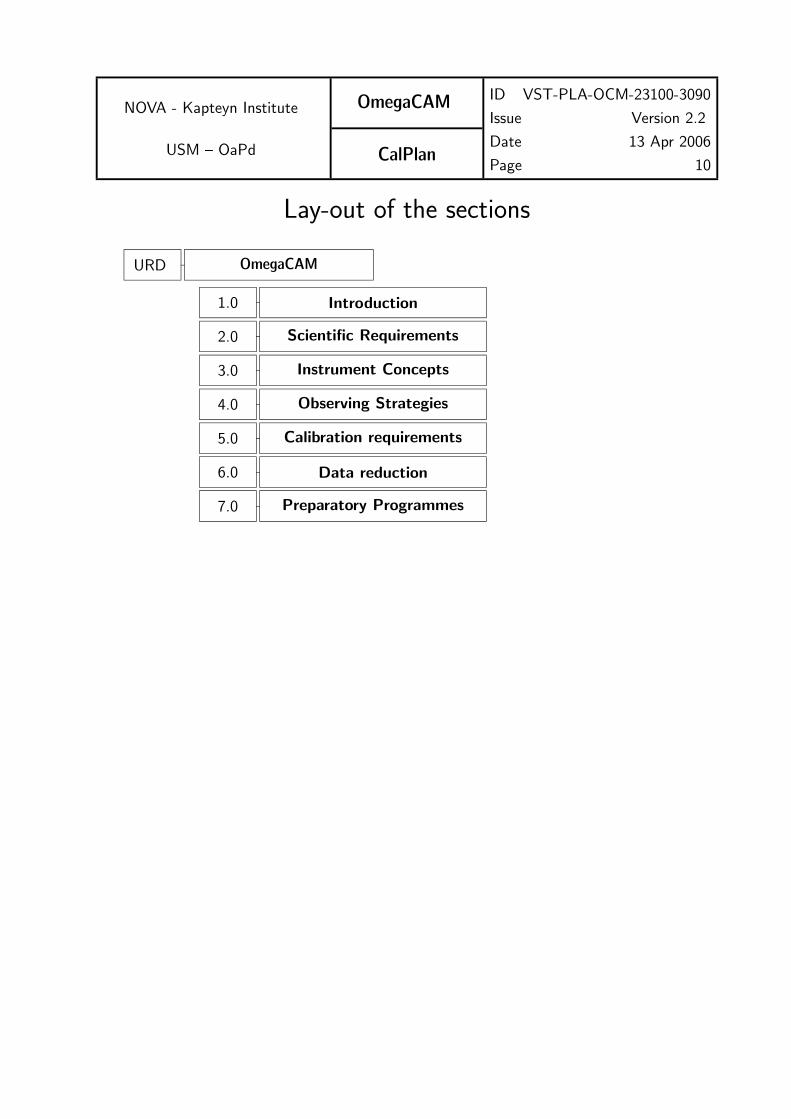
Lay-out of the sections
7.0 Preparatory Programmes
6.0 Data reduction
5.0 Calibration requirements
4.0 Observing Strategies
3.0 Instrument Concepts
2.0 Scientific Requirements
1.0 Introduction
URD OmegaCAM

NOVA - Kapteyn Institute
USM – OaPd
OmegaCAM
CalPlan
ID VST-PLA-OCM-23100-3090
Issue Version 2.2
Date 13 Apr 2006
Page 11
1 INTRODUCTION
1.1 Context
This document describes the implementations of the calibration procedures. The Baselinerequirements for the Calibrations are given in the URD, while requirements and specificationsof the data reduction of both science and calibration data are given in the Data ReductionSpecification document (DRS v1.1).
Further implementations and code descriptions are given in Users and Programmers Manual(VST-MAN-OCM-23100-3126).
1.2 Applicable documents
The following documents, of the exact issue shown, form a part of this document to the extentspecified herein. In the event of conflict between the documents referenced herein and thecontents of this document, the contents of this document shall be considered as a supersedingrequirement.
[] VST-PLA-OCM-23100-3090 OmegaCAM Calibration Plan V2.0
[] VST-PLA-OCM-23100-3051 OmegaCAM Data Reduction Specifications V1.1
[] VST-PLA-OCM-23100-3100 OmegaCAM Commissioning Plan
[] VST-PLA-OCM-23100-3010 Project Management Plan and Project Plan and Schedule
[] VST-PLA-OCM-23100-3020 Product Assurance Plan
[] VST-PLA-OCM-23100-3080 Technical Operations and Maintenance Plan
S/W deliverables depending on the URD
[] OmegaCAM Data Interface Dictionary
[] OmegaCAM Template Signature Files
[] OmegaCAM Exposure Time Calculator
1.3 Reference documents
The following documents are referenced in this document.
[] VLT-SPE-ESO-19000-1618 1.0 21/04/1999 — VLT Data flow for the VLT instru-ments Requirement Specification
[] MoU OmegaCAM - ESO

NOVA - Kapteyn Institute
USM – OaPd
OmegaCAM
CalPlan
ID VST-PLA-OCM-23100-3090
Issue Version 2.2
Date 13 Apr 2006
Page 12
[] VST-PLA-OCM-23100-3030 Safety Analysis and Compliance Assessment[] VST-TRE-OCM-23100-3040 Design Analysis, Performance Report[] VST-TRE-OCM-23100-3041 Design Analysis, Performance Report: Mechanical[] VST-ESO-OCM-23100-3042 Design Analysis, Performance Report: Detector System[] VST-TRE-OCM-23100-3043 Design Analysis, Performance Report: Electronic[] VST-SPE-OCM-23100-3050 Data Flow System User Requirements[] VST-SPE-OCM-23100-3060 Instrument Software[] VST-SPE-OCM-23100-3064 OmegaCAM Observation Software Design Description[] VST-PLA-OCM-23100-3070 MAIT and Alignment Plan[] VLT-MAN-ESO-19000-2050 FTU FITS Translation Utility User Manual[] SExtractor v2.3 User’s manual[] Eclipse User’s Guide - April 1, 2002[] FFTW manual 3.0.1[] The LDACTools Library v1.2 User’s guide[] Pipeline Documentation Ver. 1.3[] SWarp v2.0 User’s guide
1.4 Abbreviations and AcronymsAbbreviations and Acronyms used in this document
A/D Analog/digitalACS-dbase Astronomical Calibration Source databaseADC Atmospheric Dispersion CorrectorADU Analog to Digital UnitAGN Active Galactic NucleusBRD Baseline Requirements DocumentCA Calibration AnalysisCAP Calibration Analysis ProcedureCCD Charge Coupled DeviceCO Calibration ObservationCP Calibration PlanCTE Charge Transfer EfficiencyCVS Code Version SystemDFS Data Flow SystemESO European Southern ObservatoryETC Exposure Time CalculatorFOV Field of ViewFWHM Full Width at Half MaximumGRB Gamma Ray BurstGT Garanteed Time

NOVA - Kapteyn Institute
USM – OaPd
OmegaCAM
CalPlan
ID VST-PLA-OCM-23100-3090
Issue Version 2.2
Date 13 Apr 2006
Page 13
HZSS High Redshift Supernova SearchICS Instrument Control SoftwareIWS Instrument WorkstationISO Infrared Space ObservatoryIST Instrument Science TeamKBO Kuiper Belt ObjectMoU Memorandum of UnderstandingNOVA (Dutch) Nederlandse Onderzoekschool Voor AstronomieOaPd Astronomical Observatory of PaduaOB Observation blockOD Observation DescriptionOPC Observing Programme CommitteeOT Optical TransientOT Observing TemplatePPP Photometry Preparatory ProgrammePSF Point Spread FunctionQC0 Quality Control zeroQC1 Quality Control oneQSO Quasi-Stellar ObjectRPE Relative Pointing ErrorRP Routine PhaseRSRF Relative Spectral Response FunctionRTD Real Time DisplaySCP Supernova Cosmology ProjectSED Spectral Energy DistributionSSO Solar System ObjectS/N Signal/NoiseS/W SoftwareTBC To Be ConfirmedTBD To Be DefinedTBW To Be WrittenTCS Telescope Control SystemTP Target PackageTSF Template Signature FileURD User Requirement DocumentUSM Universitats Sternwarte MunchenVLT Very Large TelescopeVST VLT Survey [email protected] Wide Field Imager at the ESO 2.2m telescope

NOVA - Kapteyn Institute
USM – OaPd
OmegaCAM
CalPlan
ID VST-PLA-OCM-23100-3090
Issue Version 2.2
Date 13 Apr 2006
Page 14
2 SCIENTIFIC REQUIREMENTS -see URD
3 INSTRUMENT CONCEPT- Summary -see URD
4 OBSERVING MODES and STRATEGIES -see URD
Observing modes, observing strategies and the list of required science data observing templatesare given in the URD. The CP specifies, in addition, the OTs required for calibration purposes(Section 4.4).
4.4 Observing Templates
The Observing Templates for OmegaCAM are defined in Instrument Software Functional Spec-ifications (VST-SPE-OCM-23100-3064). The following calibration Templates are used.
- TSF– OCAM img cal biasAcquire N bias exposures, with opaque filter in optical path and shutter closed.
- TSF– OCAM img cal readnoiseBias exposures with N = 2
- TSF– OCAM img cal darkAcquire N dark exposures, with opaque filter in optical path and shutter closed.
- TSF– OCAM img cal skyflatAcquire N sky (twilight) flats, through a given filter.
- TSF– OCAM img cal domeflatAcquire N dome flats. Telescope is preset to point towards the flat-field screen (withouttracking), lamps must be switched on.
- TSF– OCAM img cal gainDomeflat exposures with texp = 2, 60, 50, 4, ..., 4, 50, 60, 2
- TSF– OCAM img cal quickDomeflat exposure with N = 1 and filter=composite
- TSF– OCAM img cal shutterDomeflat exposures with texp = 10, 0.1, 0.1, 10
In addition the following science templates are used
- TSF– OCAM img obs stare

NOVA - Kapteyn Institute
USM – OaPd
OmegaCAM
CalPlan
ID VST-PLA-OCM-23100-3090
Issue Version 2.2
Date 13 Apr 2006
Page 15
- TSF– OCAM img cal monitStare observations with N = 1, filter=composite
- TSF– OCAM img cal zpStare observations with N = 1, filter=key band
- TSF– OCAM img cal zpStare observations with N = 1, filter=user band

NOVA - Kapteyn Institute
USM – OaPd
OmegaCAM
CalPlan
ID VST-PLA-OCM-23100-3090
Issue Version 2.2
Date 13 Apr 2006
Page 16
5 BASELINE CALIBRATION REQUIREMENTS
5.0 Documentation system, Odoco
The trajectory of the data through the DFS shall be guided by the OmegaCAM documentationsystem, Odoco. The set-up of the specifications of the calibrations and its data reduction isdone in purely requirement driven fashion.
The calibration documentation system (Odoco) is a collection of files which contains a de-scription of both the requirements on OmegaCAM calibrations, as well as detailed descriptionsof the envisaged Calibration Observations (CO’s) and their analysis and data-reduction. TheOdoco is meant to avoid unnecessary duplication of work for the documentation of the vari-ous stages of the project; from the definition of basic requirements, to implementations andfinal operation and user manuals. It should also aid the documentation of development work.The Odoco was originally developed for ISO and provided a full uplink system (IOCD). Thepresent version, adapted for OmegaCAM, contains essentially only the part which deals withtext, pseudo code, recipe’s and automatic document creation. The Odoco system is essentiallya set of TeX macros, with LaTeX emulation, together with some supporting C routines. Thewhole present document is generated by Odoco, but particularly this section, listing the baselinecalibration requirements, uses some more advanced Odoco options.
The very strict document control of the original IOCD will not be maintained, but CVS (Concur-rent Versions System) will be used for local versioning control. Official versions of documentsshall be filed separately.
The contents of the Odoco will be continuously evolving and fonts are chosen for optimalreading on a computer monitor screen.
In Odoco, calibrations are specified under requirement subsections (req.’s) which are labeledwith 3-digit numbers. Each subsection contains a number of items: e.g. the objective of therequirement, a description of a specific Calibration Observation or a cross-reference to the useof a CO that has been defined under another requirement. Also, the end-results have beenspecified and the text contains various descriptions for both Template Signature Files (TSF’s)which define the creation of the observation blocks (OB) and for the off-line data analysis.Overall priorities have been defined (essential, very important, desirable) and are specified underthe item priority.
The chosen items for the descriptions of the requirements (req.’s) match well to the itemsneeded for the recipes for DFS data reductions. In section 6.1 complete listings of both thereq. items and the recipe items are given. The req.’s as listed in the Odoco will eventuallyevolve into the deliverable recipe’s.

NOVA - Kapteyn Institute
USM – OaPd
OmegaCAM
CalPlan
ID VST-PLA-OCM-23100-3090
Issue Version 2.2
Date 13 Apr 2006
Page 17
The Odoco is designed to provide a comprehensive and accessible documentation system of thevarious activities that relate to the OmegaCAM calibrations. It serves a variety of purposes,and facilitates the extraction of text from the Odoco data base into complete documents. TheOdoco can provide the following documents:
1. A listing of the Baseline OmegaCAM Calibration Requirements. Odoco containsan up-to-date listing of all the baseline requirements for the OmegaCAM calibrations,i.e. for each requirement (req.) the text under the items: Objective, When per-formed/frequency, Required accuracy, Priority. See section 5 of the URD.
2. Full documentation of the OmegaCAM calibration plan. A detailed description ofall the OmegaCAM calibration requirements and their implementations. See Section 5of the Calibration Plan. Summary sections (two digit sections) have been introducedfor a variety of calibration activities: e.g. detector specific calibrations, photometriccalibrations etc. A general overview of the OmegaCAM calibrations can be obtained byprinting the summary sections of the Odoco. In order to further ease the readability ofthis document, both each requirement and each calibration analysis procedure text itembegins with a ’one-liner’ stating the overall idea.
3. A description of the Template Signature File necessary to produce observationblocks, TSF’s. When a requirement can not be fulfilled by means of data analysis ofobservations made for another requirement, Odoco contains a detailed description of theinstrument configuration and procedures under the items Sources, observations andTSF, (TSF, Template Signature File). Note, the term selfstanding has an importantmeaning: when a requirement is selfstanding, it will normally propagate as a singlededicated calibration observation, with a single dedicated data reduction task. Conversely,non-selfstanding requirements will have more complex dependencies and often involve adata reduction of data taken for another selfstanding requirement.Under the item TSF the hierarchical structure of observation specifications is detailed(when applicable) on different lines:
– first line: observing Strategy–
– second line: observing Mode– N=
– third line: generic/base TSF–
– fourth line: specific/dependent == TSF–
4. Description of Calibration Analysis (CA). For each requirement, a specification of thedata analysis related to the requirement is given under the item CA. Standard function-alities can be quoted in the optional item Needed functionalities for CA. A detaileddescription of the implementation, which could include guidelines for the data analysis orpseudo code is given under the items CAP (Calibration Analysis Procedure). Inputs andOutputs defines the various calibration tables. Thus a document listing all the text of theitems CA, CAP and Inputs and Outputs gives a complete overview of the Calibrationdata reduction analysis.

NOVA - Kapteyn Institute
USM – OaPd
OmegaCAM
CalPlan
ID VST-PLA-OCM-23100-3090
Issue Version 2.2
Date 13 Apr 2006
Page 18
5. A reference document for timelining OmegaCAM Calibration observations. Theitems When performed/frequency and Estimated time needed can be used to designa detailed Schedule of calibration observations both in the commissioning phase (CP)and during the Routine Phase (RP).
6. A listing of the various requirements for an Astronomical Calibration Source database, (ACS-dbase).
7. The recipes belonging to the execution of requirements.
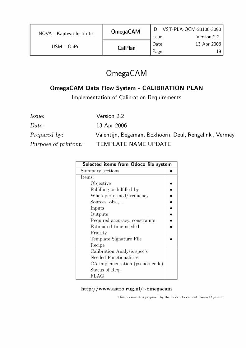
As Odoco can provide various documents with a different filtering of the source of information,each printout contains a table, listing the selection criteria. Also, the status of the printout ismarked (formal issue, or private workcopy). Each printout contains this section.
On the following pages a print-out is included which is believed to be relevant for the presentdocument.
NOVA - Kapteyn Institute
USM – OaPd
OmegaCAM
CalPlan
ID VST-PLA-OCM-23100-3090
Issue Version 2.2
Date 13 Apr 2006
Page 19
OmegaCAM
OmegaCAM Data Flow System - CALIBRATION PLAN
Implementation of Calibration Requirements
Issue: Version 2.2
Date: 13 Apr 2006
Prepared by: Valentijn, Begeman, Boxhoorn, Deul, Rengelink , Vermey
Purpose of printout: TEMPLATE NAME UPDATE
Selected items from Odoco file system
Summary sections •Items:
Objective •Fulfilling or fulfilled by •When performed/frequency •Sources, obs.,. . . •Inputs •Outputs •Required accuracy, constraints •Estimated time needed •PriorityTemplate Signature File •RecipeCalibration Analysis spec’sNeeded FunctionalitiesCA implementation (pseudo code)Status of Req.FLAG
http://www.astro.rug.nl/∼omegacam
This document is prepared by the Odoco Document Control System.
NOVA - Kapteyn Institute
USM – OaPd
OmegaCAM
CalPlan
ID VST-PLA-OCM-23100-3090
Issue Version 2.2
Date 13 Apr 2006
Page 20
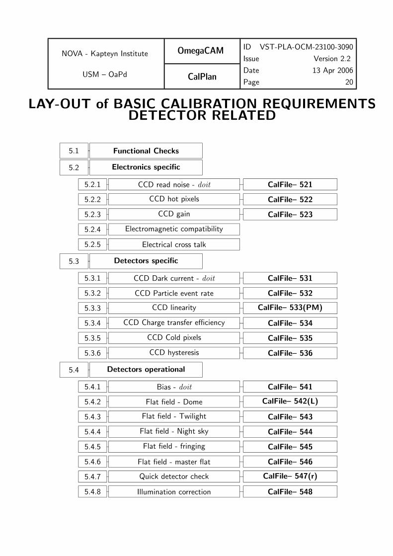
LAY-OUT of BASIC CALIBRATION REQUIREMENTSDETECTOR RELATED
5.1 Functional Checks
5.2 Electronics specific
5.2.1 CCD read noise - doit CalFile– 521
5.2.2 CCD hot pixels CalFile– 522
5.2.3 CCD gain CalFile– 523
5.2.4 Electromagnetic compatibility
5.2.5 Electrical cross talk
5.3 Detectors specific
5.3.1 CCD Dark current - doit CalFile– 531
5.3.2 CCD Particle event rate CalFile– 532
5.3.3 CCD linearity CalFile– 533(PM)
5.3.4 CCD Charge transfer efficiency CalFile– 534
5.3.5 CCD Cold pixels CalFile– 535
5.3.6 CCD hysteresis CalFile– 536
5.4 Detectors operational
5.4.1 Bias - doit CalFile– 541
5.4.2 Flat field - Dome CalFile– 542(L)
5.4.3 Flat field - Twilight CalFile– 543
5.4.4 Flat field - Night sky CalFile– 544
5.4.5 Flat field - fringing CalFile– 545
5.4.6 Flat field - master flat CalFile– 546
5.4.7 Quick detector check CalFile– 547(r)
5.4.8 Illumination correction CalFile– 548

NOVA - Kapteyn Institute
USM – OaPd
OmegaCAM
CalPlan
ID VST-PLA-OCM-23100-3090
Issue Version 2.2
Date 13 Apr 2006
Page 21
LAY-OUT OF BASIC CALIBRATION REQUIREMENTScont’d
5.5 Astrometric
5.5.1 Focal plane position of camera
5.5.2 Telescope Pointing
5.5.3 Telescope and rotator tracking
5.5.4 PSF anisotropy CalFile– 554
5.5.5 The astrometric solution - doit SeqFile– 634(CR)
5.5.6 Astrometry - Guide CCD’s CalFile– 556
5.6 Photometric
5.6.1 Shutter timing
5.6.2 Photometric monitoring CalFile– 562(T)
5.6.3 Zeropoint key bands doit CalFile– 563
5.6.4 Zeropoint user bands CalFile– 564
5.6.5 Filter band pass - user− >key CalFile– 565(C)
5.6.6 Rotation angle - ADC, rotator
5.6.7 Linearity
5.6.8 Detection limit
5.6.9 Secondary standards CalFile– 569
5.7 Alignment
5.7.1 Camera focus/tilt
5.7.2 Ghosts - ADC
5.8 Telescope
5.9 End to end tests

NOVA - Kapteyn Institute
USM – OaPd
OmegaCAM
CalPlan
ID VST-PLA-OCM-23100-3090
Issue Version 2.2
Date 13 Apr 2006
Page 22
5.1 Functional ChecksThe commissioning plan [VST-PLA-OCM-23100-3100] lists a large set of acceptance tests.Most of these test are engineering tests and are not repeated here. Those engineering testswhich can be executed with requirements from the URD/CP contain the proper reference tothe URD in the commissioning plan.
The technical operations and maintenance plan [VST-PLA-OCM-23100-3080] describes activ-ities during Routine Phase (RP). Both the URD, CP and the DRS specifies the requirementsand the activities for fulfilling these requirements during RP. The label RP always points toactivities that shall be followed in the technical operations and maintenance plan.
5.2 Detector Electronics specific CalibrationsSection 5.2 contains the requirements for the characterization of the detector system on elec-tronics level, while Section 5.3 lists more detector specific calibrations. The separation betweenthese Sections is somewhat artificial. In Section 5.4 more daily characterizations are listed,which involve the flatfielding and de-biasing. Requirements which are foreseen to become‘workhorses’ are labeled with doit, e.g. a quick daily evaluation of the read noise serves as adaily health check.
The CCD’s are operated at one port; electrical cross talk is not expected to significantlyaffect the observations. However, as a check, the absence of significant cross-talk is verified(req.525).
The hot pixel (req.522) and cold pixel (req.535) characterization are combined in the indi-vidual weight maps (seq.– 633).
As the standard read-out time of the arrays is already very fast, ∼ 40 sec , no extra fastread-out mode is supported in the characterization.
CCD rebinning mode and windowing mode are not supported in the calibration and datareduction procedures.
5.2.1 Req. — CCD read noise - doit
Objective:Measure the CCD read noise (in ADU’s) as a standard health check.The read noise is measured from pairs of bias exposures. The rms scatter of the differencesbetween two exposures is computed and divided by
√2. Monitor variations. This is the first
order daily health check.
Fulfilling or fulfilled by:Selfstanding
Required accuracy, constraints:Readout noise less than 5e−.Variation in readout noise w.r.t. reference value less than 0.5e−.

NOVA - Kapteyn Institute
USM – OaPd
OmegaCAM
CalPlan
ID VST-PLA-OCM-23100-3090
Issue Version 2.2
Date 13 Apr 2006
Page 23
These are lab values. The corresponding limits in ADU can be calculated using the e−/ADUconversion factor from req.523.
When performed/frequency:
daytime- Commissioning, during all operations: daily health check.
Estimated time needed:
Observation: 5 min. Reduction: 5 sec/CCD.
Inputs:
2 raw bias framesCalFile– 521 Readout noise previous version
Outputs:
CalFile– 521 Readout noise in ADU’sThe CalFile correponds to QC parameter read noise (a single number).
TSF:
Mode– Stare N=2(TSF– OCAM img cal bias, N=2)= TSF– OCAM img cal readnoise
5.2.2 Req. — hot pixels
Objective:
Determine CCD bad/hot pixels.
Use the master bias frame (req.541) to determine bad/hot pixels. Calculate a backgroundmap of the master bias frame and subtract it. This is done e.g. to avoid detecting inducedcharge structures as hot pixels. 5σ outliers in the background-subtracted master bias frameare bad-hot pixels. These pixels should be recorded and ignored (assigned a weight of 0)in dedithering and dejittering, as well as source extraction. For this purpose the bad/hotpixel map is used to assign a weight of zero to the affected pixels in the weight map (seq.–633). The search for hot pixels would also identify traps.
Fulfilling or fulfilled by:
Additional data reduction of CalFile– 541 Master Bias frame to determine hot pixels
Required accuracy, constraints:
Number of hot pixels to be determined by experience/lab values.The total number of bad pixels (hot pixels + cold pixels) is less than 80000 (checked inreq. 535 Cold pixelsDifference in number of hot pixels w.r.t. reference value, less than 100.
When performed/frequency:
daytime- Commissioning, in RP twice per week.

NOVA - Kapteyn Institute
USM – OaPd
OmegaCAM
CalPlan
ID VST-PLA-OCM-23100-3090
Issue Version 2.2
Date 13 Apr 2006
Page 24
Estimated time needed:Observation: None. Reduction: < 20 sec./CCD.
Inputs:CalFile– 541 Master Bias frameCalFile– 522 Bad/hot pixel map previous version
Outputs:CalFile– 522 Bad/hot pixel map, number of hot pixels
TSF:Use master bias (req.541)
5.2.3 Req. — CCD gain
Objective:Determine CCD gain and variation with timeDetermine the conversion factor between the signal in ADU’s supplied by the readout elec-tronics and the detected number of photons (in units e−/ADU) and monitor variations intime.The gain factors are needed to convert ADU’s in raw bias-corrected frames to the numberof electrons, i.e. detected photons.Take two series of 10 dome flatfield exposures with wide range of exposure times. De-rive the rms of the differences of two exposures taken with similar exposure (integrationtime). Exposure differences of pairs should not exceed 4%. The regression of the square ofthese values with the median level yields the conversion factor in e−/ADU (assuming noisedominated by photon shot noise).
Fulfilling or fulfilled by:Selfstanding, also measures detector linearity (req.533).
Sources, observations, instrument configurations:Dome flat field exposures on lamp, with texp= 2, 60, 50, 4, 8, 40, 30, 1, 16, 24, 24, 16, 1,30, 40, 8, 4, 50, 60 and 2 seconds. Use r’ filter.
Required accuracy, constraints:Accuracy: In units of e−/ADU, from lab values or found empirically. Variation in time lessthan 1%.
When performed/frequency:daytime- Commissioning, in RP once week.
Estimated time needed:Observations: 1 hour. Reduction: 3 min./CCD.
Inputs:Number of raw domeflats such that for each exposure time there are two different rawdomeflats. The total number of raw domeflats has to be larger than 4.A raw domeflat with a short exposure time.

NOVA - Kapteyn Institute
USM – OaPd
OmegaCAM
CalPlan
ID VST-PLA-OCM-23100-3090
Issue Version 2.2
Date 13 Apr 2006
Page 25
A raw domeflat with a long exposure time.CalFile– 541 Master Bias frameCalFile– 523 Conversion factor e−/ADU older versions.
Outputs:CalFile– 523 Conversion factor e−/ADUThe CalFile– 523 corresponds to the QC parameter gain (single number).
TSF:Mode– Stare N=20(TSF– OCAM img cal domeflat, texp= 2, 60, 50, 4, 8, 40, 30, 1, 16, 24, 24, 16, 1, 30,40, 8, 4, 50, 60, 2 s.).= TSF– OCAM img cal gain
5.2.4 Req. — Electromagnetic Compatibility
Objective:Verify whether any external source (e.g. dome drives, control systems) is not interfering inthe CCD overall detector system, leading to additional, mostly non-white noise.Technical specifications require less than 20% effect on read-out noise, for external interfer-ence and less than 10% effect on read-noise for internal OmegaCAM interference.If electronic interference occurs then this will put constraints on the operation of the instru-ment. For example, if interference occurs during movement of the telescope, one cannotread the CCDs and move the telescope at the same time,.Interference is detected by measuring the read noise (req.521) under operational conditions.This means doing bias measurements while the telescope and/or dome are moving.
Fulfilling or fulfilled by:repetition of CCD read noise calibrations req.521.
Sources, observations, instrument configurations:Raw bias frames obtained while the telescope/dome are moving.
Required accuracy, constraints:Difference between read noise under operational conditions and the standard read noisemeasurement should be smaller than 20% for external and 10% for internal causes of inter-ference.
When performed/frequency:Day time; Commissioning; once a year; every time a major system change has been made;To be determined by experience
Estimated time needed:Observations: 4 hours. Reduction: 1 min./CCD.
Inputs:raw bias frames, obtained when telescope/dome were moving.CalFile– 521 CCD read noise

NOVA - Kapteyn Institute
USM – OaPd
OmegaCAM
CalPlan
ID VST-PLA-OCM-23100-3090
Issue Version 2.2
Date 13 Apr 2006
Page 26
Outputs:OK/non-conformance flag.
TSF:Mode– Stare N=2(TSF– OCAM img cal bias, N=2)= TSF– OCAM img cal readnoise while telescope and/or dome are moving.
5.2.5 Req. — Electrical cross talk
Objective:Although crosstalk is not detectable in the WFI, and only one part per CCD is used, thesharing of one FIERA by 16 CCD’s opens up the possibility of cross talk.Observe a bright (mag 5-8) star at 16 different chips (1 FIERRA serves 16 chips).
Fulfilling or fulfilled by:Selfstanding
Sources, observations, instrument configurations:Bright star, mag 5-8
Required accuracy, constraints:10−5
When performed/frequency:Nighttime. Commissioning.
Estimated time needed:1 hour
Outputs:Conformance flag
TSF:Mode– Stare N=1(TSF– OCAM img obs stare, N=1, filter=key band)

NOVA - Kapteyn Institute
USM – OaPd
OmegaCAM
CalPlan
ID VST-PLA-OCM-23100-3090
Issue Version 2.2
Date 13 Apr 2006
Page 27
5.3 Detectors specific calibrations
5.3.1 Req. — CCD Dark Current - doit
Objective:Measure CCD dark current (in ADU/pixel/hour) for qualification purposes of the detectorchain (qualification and trend analysis). The particle event rate will be determined on thefly.Repeating the test with the dome lights on will provide information on possible light leaks.Three one hour exposures are taken with the shutter closed. After rejection of the cosmicray events, the signal above the bias level is the dark signal.For the reduction of the science observations the subtraction of the sky brightness willinclude the dark current, and a separation of both contributions is normally not required.Do a trend analysis.
Fulfilling or fulfilled by:Selfstanding, also used to compute the particle event rate.
Sources, observations, instrument configurations:Three 1 hour exposures with shutter closed. Dome lights either on or off for all exposures.
Required accuracy, constraints:Dark count rate should be less than the equivalent of 3 e−/pixel/hour in ADUs excludingbad pixels. (This corresponds to 1.5 ADU/pixel/hour for nominal gain.)Accuracy of determining particle event rate 1 particle/cm2/hour.Particle event rates should be identical for each chip.
When performed/frequency:Daytime (if dome and camera are proven to be light tight enough) - Commissioning; onceper week. Alternatively, one dark frame per day could be taken, followed by a trend analysisonce/month.
Estimated time needed:Observation: 3 hours. Reduction: < 1 min./CCD.
Inputs:3 raw dark framesCalFile– 541 Master Bias frameLab valuesCalFile– 531 Dark count rate for each CCD older versions.CalFile– 532 Particle event rate older version.
Outputs:CalFile– 531 Dark count rate for each CCD in ADU/pixel/hourCalFile– 532 Particle event rate in particles/cm2/hourIn ESO DFS terminology these outputs are not a CalFile, but a single number.

NOVA - Kapteyn Institute
USM – OaPd
OmegaCAM
CalPlan
ID VST-PLA-OCM-23100-3090
Issue Version 2.2
Date 13 Apr 2006
Page 28
TSF:
Mode– Stare N=3TSF– OCAM img cal dark exposure time 1 hour each, shutter closed. Dome lamp eitheron or off for all exposures
5.3.2 Req. — CCD Particle Event Rate
Objective:
Determine CCD particle event rate by evaluating dark current measurements.
Verify the absence of a local radiation source affecting the detector. The data will beinspected for significant differences of the rates on different chips, and will be screened forlocal effects.
Fulfilling or fulfilled by:
Data reduction of req. 531 Dark current
Required accuracy, constraints:
better than 1 particle/cm2/hour
When performed/frequency:
Commissioning and when dark current is measured.
Outputs:
CalFile– 532 Particle event rate in particles/cm2/hour
5.3.3 Req. — CCD Linearity
Objective:
Characterize the linearity of the system over the full dynamic range of the A/D converter.
Both the overall absolute linearity of the system and the pixel-to-pixel variation in linearityare of interest.
The overall linearity of the system can be obtained by measuring the counts as a functionof exposure time for a series of dome flats. The data to use for this can be the same as forthe measurement of the Gain (req.523, q.v.)
The pixel-to-pixel variation in the linearity is obtained by dividing a flatfield with a meanexposure level of more than 30000 ADU by a flatfield with an exposure level of less than1000 ADU. Pixels that deviate more than 5σ from the mean, in this divided image, havean anomalously high nonlinearity. This map of nonlinear pixels may be used in conjunctionwith the hot and cold pixel maps to produce a map of bad pixels. One can use suitable longand short exposures from the measurements of the Gain (req.523, q.v.) for this.
In addition, during a cloudy night, once per year, the linearity will be checked by takingvarious exposures with a variety of exposure times on the dome screen. These data will besubject to interactive analysis.
Fulfilling or fulfilled by:
Data reduction of req. 523 CCD Gain

NOVA - Kapteyn Institute
USM – OaPd
OmegaCAM
CalPlan
ID VST-PLA-OCM-23100-3090
Issue Version 2.2
Date 13 Apr 2006
Page 29
Required accuracy, constraints:better than 1% on the photometric scale
When performed/frequency:daytime- Commissioning, in RP once per month, dark dome test once/year
Estimated time needed:Observation: None
Inputs:Raw dome flatfieldsCalFile– 541 Master Bias frame
Outputs:CalFile– 533P CCD Linearity Plot A measure of the overall nonlinearity can be obtainedfrom this plot
CalFile– 533M CCD Linearity map A map of (anomalously) non-linear pixels can be usedin conjunction with hot and cold pixel maps.
TSF:Use same raw data as for req. 523 CCD gain
5.3.4 Req. — CCD Charge Transfer Efficiency
Objective:Characterize horizontal and vertical transfer efficiency (CTE) per single transfer (in units ofthe fraction of the charge actually transferred).Taken from [email protected]: Ten flatfields are taken with 50 vertical and 50 horizontal overscanpixels and a mean exposure level of about 20000 ADU’s. The mean is computed andcorrected for the bias. Average signal levels are determined in the two overscan regionsas well in the light sensitive pixels just preceeding the respective overscan pixels. Anysignal found in the overscan pixels was due to non-unity CTE lost from the neighbouringlight-sensitive pixels. The fractional charge still remaining in the light-sensitive pixels is theCTE.Note added after analysing Bias behaviour in overscan regions on OmegaCAM CCDs (seetest report Notes on OmegaCAM bias level- Nov 2003): The test report shows that thereis significant reminiscence in the detector/amplifier chain with typical time scale of abouta second. Therefore both the vertical and the horizontal overscan regions are affected bythis reminiscent signal (only the upper 50 rows of the Y-overscan region are free from thissignal). Thus the above decribed method for WFI is not expected to deliver very usefulinformation on CTE.Alternative: it might be more practical and informative to inspect the tails in X and Y ofvery bright stars.

NOVA - Kapteyn Institute
USM – OaPd
OmegaCAM
CalPlan
ID VST-PLA-OCM-23100-3090
Issue Version 2.2
Date 13 Apr 2006
Page 30
Fulfilling or fulfilled by:selfstanding but related to masks for req. 541 Bias - doit, req. 522 Hot pixels andreq. 535 CCD Cold Pixels.
Sources, observations, instrument configurations:Dome flat field- lamp. Use r’ filter.Alternative none- use req. 525 crosstalk.
Required accuracy, constraints:CTE > 0.999995 per parallel or serial shift.Note, that a small fraction of the OmegaCAMCCDs will have a CTE slightly below thesevalues.
When performed/frequency:daytime- Commissioning, in RP once half year alternative additional data reduction ofreq. 525 Cross talk
Estimated time needed:30 min.
Inputs:CalFile– 541 Master Bias frame
Outputs:CalFile– 534 charge transfer efficiency factors
TSF:template withdrawn at PAE.
5.3.5 Req. — CCD Cold Pixels
Objective:Identify cold pixels.
Cold pixels should be recorded and ignored (assigned a weight of 0) in dedithering/dejitteringand source extraction. For this purpose the bad/cold pixel map, together with the hot pixelmap (req.522) is used to assign a weight of zero to the affected pixels in the weight map(seq.– 633).Cold pixel maps are constructed from reduced dome (req.542) or twilight (req.543) flats.The flatfield is smoothed. The smoothed flat is used to flatten the flat. In this flatfieldedimage, pixels that are outside a given range (0.96-1.04) are taken to be cold pixels. Notethat this invalidates any pixel whose gain differs significantly from its immediate neighbours.In particular, this also identifies pixels that are bright relative to their neighbours as ”cold”.Note, that pixels above the threshold are formally not ”cold”, but are flagged annyway. Inthe end, hot plus cold pixel map are combined in weightmap.
Fulfilling or fulfilled by:Requires data reduction of master domeflat (req.542) or twilight (req.543) flat frames.

NOVA - Kapteyn Institute
USM – OaPd
OmegaCAM
CalPlan
ID VST-PLA-OCM-23100-3090
Issue Version 2.2
Date 13 Apr 2006
Page 31
Sources, observations, instrument configurations:
Use master dome- or twilight flat. Use r’ filter.
Required accuracy, constraints:
Quality Check: Number of hot pixels to be determined by experience/lab values. The totalnumber of bad pixels (hot pixels + cold pixels) is less than 80000. Difference in number ofcold pixels w.r.t. reference version less than 100.
When performed/frequency:
daytime- Commissioning, in RP once per 3 months.
Estimated time needed:
Observation: None. Reduction: < 20 sec./CCD.
Inputs:
CalFile– 535 Cold pixel map previous versionCalFile– 542 Dome flat or CalFile– 543 Twilight flat
Outputs:
CalFile– 535 Cold pixel map
TSF:
Use master dome- (req.542) or twilight flat (req.543)
5.3.6 Req. — CCD Hysteresis, strong signal
Objective:
Quantify the effect of CCD signal reminiscence at timescales larger than 60 sec.
Reminiscence of a strong signal (a saturated star) in subsequent observations (“ghosts”)is a potentially debilitating problem for data reduction and interpretation. The absence ofthis effect should be verified by observations of very bright objects and subsequent darkexposures.
If “sources” are detected in the dark frames at the pixel positions of bright sources in thefirst field, signal reminiscence is a problem, which can be characterized by the decay timeof a strong signal.
Fulfilling or fulfilled by:
Selfstanding
Sources, observations, instrument configurations:
Observe a field containing very bright objects followed by a few dark exposures. Number ofdark exposures to be determined by experience. Do this on more chips to be determined byexperience.
When performed/frequency:
Commissioning.
Estimated time needed:
2 hours

NOVA - Kapteyn Institute
USM – OaPd
OmegaCAM
CalPlan
ID VST-PLA-OCM-23100-3090
Issue Version 2.2
Date 13 Apr 2006
Page 32
Outputs:When significant effect is detected:CalFile– 536 CCD Hysteresis, containing the signal decay time.
TSF:Mode– stare N=2TSF– OCAM img obs stareand TSF– OCAM img cal dark

NOVA - Kapteyn Institute
USM – OaPd
OmegaCAM
CalPlan
ID VST-PLA-OCM-23100-3090
Issue Version 2.2
Date 13 Apr 2006
Page 33
5.4 Detectors operational specific calibrations
In this Section req.’s are listed which are essential related to the daily operations of theacquisition of the science data.
For all detector and photometry related calibrations each CCD is characterized independentlyof the others. (Only in the case of astrometric solutions, data of various chips is combined).
A set of calibration lamps together with a dome screen is used to monitor the health of theinstrument and to measure the fine structure of the flatfield.
The calibration lamp system contains two sets of 4 commercial 12-24V halogen lamps each.Each set is operated independently. Each set is stabilized in current supply (one unit for wholeset). Lamps are switched on/off with a gradual increase/decrease of the current over a timespanof 3-5 minutes. Implementation TBC. When operated this way, the nominal lamp instabilitiesare expected to be of the order of 0.05%/hour for a timespan of 200 hours of lamp operations(private comm. Philips Labs). For a nominal 1-2 hour/day of operations the lamp instabilityis expected to be of the order 1.5-3 % per month. The lamp instabilities are expected to bestrictly linear after 100 hours of operations. When operating two sets at different rates, say oneset 1 hour/day the other set at say 1 hour/two weeks a full characterization of the lamp stabilitycan be achieved at accuracies better than a few percent on a monthly basis. Also continuityafter failure of one lamp can be obtained. The accuracy is better than required as also otherfactors, like dust on the lamps and background light will affect the effective illumination of thescreen. Altogether, the system is expected to provide control over the illumination of the screenwith an accuracy better than 5-10%, which will be used for a daily health check on the overalthroughput/health of the detectors (req. 547 Quick detector responsivity and health check).This activity provides a deliberate redundancy with flatfield measurements on the dome screen(req. 542 Flat field – dome key bands–doit), in order to provide the necessary cross-checkin the off-line calibration analysis procedures. Next to the health checks taken during thenight, a standard health check using a photometric standard field (also providing the absolutephotometry is specified in req. 562 Photometric Calibration – Monitoring). The system oflamps, flatfields measurements, quick checks using the lamps and health checks on the skyon photometric standard fields is designed to support the photometric calibration of a SurveySystem, for many years to come. The system provides redundancy faciltating cross-checks andhas a typical maintenance/update frequency once/month.
The calibration of science data can be divided in three steps.
1 Removing the effects of bias and differential gain.
2 Relating the overall gain, and hence counts S(x, y) to a photometric scale
3 Relating the x, y coordinates to an astrometric reference system.
The raw science and standard images record S(x, y) counts in pixel x, y, that are related tothe incident photon flux I(x, y, λ) by:
S(x, y) = b(x, y) + G∫
g(x, y, λ)I(x, y, λ)dλ,

NOVA - Kapteyn Institute
USM – OaPd
OmegaCAM
CalPlan
ID VST-PLA-OCM-23100-3090
Issue Version 2.2
Date 13 Apr 2006
Page 34
with G the ADU conversion factor, g(x, y, λ) the quantum efficiency or gain as function ofposition and wavelength, and b(x, y) the bias offset.
The photometric and astrometric calibration (steps 2 and 3) are the subject of Sections 5.5and 5.6, respectively. Here we list the calibration data necessary to remove the effects of biasand gain variation over the image. These calibration data include:
• Bias to subtract residual pattern in the bias offset.
• Flatfields to correct for non-uniform gain.
• Fringe maps to remove the fringe-patterns
• Weight maps to determine the relative contribution of each pixel when image data arecombined,
A first-order approximation of the bias level in an image is provided by the median of theoverscan region. A more accurate determination of the bias offset takes into account thefollowing two effects: i) the bias level grows to its asymptotic level in the first few hundredlines, and ii) the bias level depends on the total signal in a given line. Therefore, an initialbias correction—the overscan correction, is applied by averaging the overscan pixels for eachline, and subtracting this value from that line. Also, experience with the WFI has shown thepresence of residual patterns in the bias offset over the image area. Under the assumption thatthese patterns are also present in OmegaCAM data its characterization by means of a masterbias frame is specified in req.541.
Note that the OmegaCAM calibration and image pipelines support several overscan correctionmethods (not doucumented separately in every requirement). It is imperative that all calibrationdata is derived using the same overscan correction method.
The gain, g(x, y, λ), incorporates the wavelength-dependent pixel-to-pixel variation in trans-missivity of the different lightpaths through the telescope optics, filters and detectors. Thegain can be approximated with
g(x, y, λ) = gDQE(λ)gff (x, y),
with gff (x, y) the pixel-to-pixel variation in the gain, and gDQE(λ) the overall detector quantumefficiency (zeropoint), at gff = 1, which is subject to photometric calibration (Section 5.5).
The characterization of the pixel-to-pixel variation of the gain, the flatfield, is obtained byobserving a spatially uniform source of illumination. A normalized version of such an imageprovides a measure of the relative variation of the gain over the image area, gff (x, y). Notethat this flatfield measures a combination in the pixel-to-pixel gain variation and the variationin transmissivity of the different light paths through the telescope optics and filters.
The ideal flatfield observation is:i) uniformly illuminatedii) bright, to minimize errors due to photon noise,iii) of constant color, preferably a color that is the same as the night sky.
Several methods to determine a flatfield will be operational. However, each method suffers fromdifferent drawbacks. The various characterizations of the flat field, the dome, twilight, and

NOVA - Kapteyn Institute
USM – OaPd
OmegaCAM
CalPlan
ID VST-PLA-OCM-23100-3090
Issue Version 2.2
Date 13 Apr 2006
Page 35
night sky flats, are specified under the req.542-545, while the eventual master flatfield to beapplied to science and standard field observations, is constructed from a suitable combinationof the dome, twilight and night sky flat fields (req.546).
Dome flats (req.542) are obtained by observing in telescope screen park position a fixeddomescreen relatively uniformly illuminated by the calibration lamp with a stabilizing powersupply. The illumination is not sufficiently uniform to measure large scale variations, and thecolor is very different from the night sky.
Twilight flats (req.543) are based on a bright, uniform source of illumination (twilight sky),that is unfortunately not of constant brightness and color. Unfortunately the ’twilight gradient’precludes measurement of the largest scale gain variation. Also bright objects may be visibleeven at twilight, which provides an additional complication.
Night sky flats (req.544), obtained by combining a large number of science observations, mostclosely mimic the illumination properties of the science frames themselves. These are the onlyflatfields usable for measuring the largest scale gain variations. Unfortunately, the assumptionthat the illumination is uniform (except for astronomical sources of course), has proven to beinvalid on WFI (e.g Manfroid et al, 2000). It remains to be seen how large this problem of ”skyconcentration” will be for OmegaCAM. Computing the night sky flat is also a computationallyexpensive process, both because of the large numbers of frames involved, and because the needfor a proper masking of bright objects in the field. Fortunately, this measurement may also beusable for the fringe correction.
The master flatfield (req.546), to be applied to science and standard field observations, isconstructed from a suitable combination of the dome, twilight and night sky flat.
The approximation that the pixel-to-pixel variation in the gain is independent of wavelength is infact incorrect. Interference effects, mainly in the filters and thinned silicon layers of the CCDs,introduce wavelength dependent gain variations that vary on small angular scales. Since mostsources are continuum sources, and only the convolution ∫ g(λ)I(λ)dλ is measured, this effectcan be ignored when measuring source fluxes. However, due to variable strength of several skylines, mostly apparent at the long wavelengths, the background will exhibit so-called fringingpatterns, which can change during the night. This requires an additional calibration step forbands redward of R: the construction of suitable fringed background images (req.545).
The weight map is an important auxiliary file, which is used in several image processing steps.The weight map is intimately linked to the flatfields and therefore its construction is alsoaddressed in this section.
Whenever individual pixels are combined, either in constructing source lists necessary for pho-tometric and astrometric calibration, or in the coaddition of different frames, the OmegaCAM-reduction pipeline uses variance weighting (weight= 1/σ2). The inverse variances are recordedin weight maps, which are computed as part of the image pipeline (ref. seq.– 633).
The debiased images record S(x, y) counts in pixel x, y, that are related to the photon fluxI(x, y) by:

NOVA - Kapteyn Institute
USM – OaPd
OmegaCAM
CalPlan
ID VST-PLA-OCM-23100-3090
Issue Version 2.2
Date 13 Apr 2006
Page 36
S(x, y) = GgDQEgff (x, y)I(x, y),
Since photon shot-noise is much larger than the read-out noise, the rms-noise in the raw datais given by:
σS(x, y) = G(gDQEgff (x, y)I(x, y))1/2 = (GS(x, y))1/2.
Once data has been flatfielded (S ′ = S/gff ), the counts are given by:
S′(x, y) = GgDQEI(x, y),
and the rms-noise by:
σS′(x, y) = G(gDQEgff (x, y)I(x, y))1/2)/gff = (GS′(x, y)/gff )1/2
The photon flux I(x, y) is a sum of a uniform background Iback plus sources Isrc(x, y). Since,the surface brightness of the sky is (much) larger than the surface brightness of most sources,the rms-noise is given by:
σS′(x, y) = G[gDQEIback/gff (x, y)]1/2 = (GS′
back/gff )1/2
Hence, the rms-noise in an image is the product of a factor ((GS ′
back)1/2) that is constant over
one image, but will vary between images, and a factor (g−1/2
ff ), the inverse of the square-root
of the flatfield, which varies over the image.
To account for image defects the weight map will give bad pixels a weight of zero. Bad pixelsinclude hot (req.522) and cold (req.535) pixels, as well as pixels affected by saturation, cosmicrays and satellite tracks, as determined in seq.– 633.
5.4.1 Req. — Bias - doit
Objective:Determine master bias frame.The signal in raw scientific frames contains a component that is due to a bias current.This component shows up as an offset to the signal. The bias-offset has the followingcharacteristics: i) the bias level grows to its asymptotic level in the first few hundred lines,and ii) the bias level depends on the total signal in a given line. Therefore, an initial biascorrection—the overscan correction, is applied by averaging the overscan pixels for eachline, and subtracting this value from that line. It is noted that the bias level may jumpsignificantly after a cold restart of the FIERA.In addition, the bias offset exhibits a residual pattern, which is measured by the master biasframe. To construct the master bias a series of 10 zero-second bias exposures is overscan-corrected, and then averaged, rejecting 5σ outliers (σ = dispersion of the 10 bias exposuresof individual pixels), due to particle hits during read-out. The resulting master bias frameswill be used for the correction of all frames. For each master bias frame the mean value foreach CCD chip will be determined and evaluated in a trend analysis.As the readout noise dominates the rms scatter in the bias frames, while the shotnoise ofthe sky background dominates the rms scatter on the sky images, which is nominally muchlarger than the readout noise, it is sufficient to characterize the bias value at individual pixelswith an accuracy of (readout noise/
√10).

NOVA - Kapteyn Institute
USM – OaPd
OmegaCAM
CalPlan
ID VST-PLA-OCM-23100-3090
Issue Version 2.2
Date 13 Apr 2006
Page 37
A comparison with a previous master bias frame will be done as an evaluation of the overallhealth of the instrument and the quality of the data. This will thus measure short-termvariations. Long term variations can be assessed using trend analysis.A comparison of the mean level with laboratory values will be used as an overall qualitycheck.
Fulfilling or fulfilled by:Selfstanding. Raw data are also used for req. 522 Bad/hot pixelsCalfiles used by: req. 542 Dome flat, req. 543 Twilight flat req. 544 Night sky flatseq. 632 Trim, de-bias, flatfield
Sources, observations, instrument configurations:10 observations with 0 (zero) seconds exposure time.
Required accuracy, constraints:The required accuracy per pixel in the master bias frame is “nominal read-outnoise/
√10”.
For the quality check: Since an overscan correction is performed, the deviation of the meanlevel of master bias (bias level) from zero, should be less than TBD.
When performed/frequency:daytime- Commissioning, in RP initially daily. Later the frequency is to be determined byexperience.
Estimated time needed:Observation: 15 min. Reduction: < 2 min./CCD.
Inputs:Raw data bias framesCalFile– 541 Master Bias frame previous versionsLaboratory values of bias levels.
Outputs:CalFile– 541 Master Bias frame to be used by seq. 632 de-bias flat field
TSF:Mode– Stare N=10TSF– OCAM img cal bias
5.4.2 Req. — Flat-field - dome key bands + user bands - doit
Objective:Determine master dome flat frame for both Keybands and Userbands.
Master dome flats are obtained through an average with sigma rejection procedure on astack of raw dome flats, intended to reduce photon shot noise, remove cosmic rays.During the lifetime of OmegaCAM the dome flatfields shall be measured for the 4 keybandsand the key-composite filter at least once/week. Thus at least within 3 days of the takingof science data a dome flatfield in the key passband will be available.

NOVA - Kapteyn Institute
USM – OaPd
OmegaCAM
CalPlan
ID VST-PLA-OCM-23100-3090
Issue Version 2.2
Date 13 Apr 2006
Page 38
The sequence of master dome flatfields in the keybands, acquired over periods of monthsto years will be used to perform a trend analysis on the long term stability of the instru-ment and lamp which illuminates the dome flatfield. With the exception of the effects ofthe unstability of the lamp, this trend analysis is redundant with that obtained from bothreq. 563 Photometric Calibration - zeropoint key bands - doit and that of req. 562 Photo-metric Calibration - monitoring. Thus, by combining the results of these req.’s an accuratedescription of the behaviour of the lamp is feasible. The prediction of the behaviour of thelamp is a result, which will be used as an input for req. 547 Quick detector responsivitycheck.
The dome flatfields will be used on an individual CCD chip level. The relative variations ofthe quantum efficiciency between individual CCD chips will be measured by req. 563 Pho-tometric Calibration - zeropoint key bands - doit.
The redundancy between various measurements of req. 563 Photometric Calibration -zeropoint key bands - doit and req. 542 Master Domeflat at keybands will be used toevaluate the relative chip-to-chip gain variations, and in due time, when advanced insight inthis item is achieved, this knowledge might be used to further optimize observing scenarios.
The cross-calibration/handshaking of two lamp sets will be done during a transition periodof about one week. During that week observations will be taken with both lamp sets.Template TSF–OCAM img cal domeflat has a parameter which one of the two lamp setswill be used It is anticipated that about every 3 months a new set will become operational.During this transition period of about a week both lamps sets will be observed sequentially.Also TSF-OCAM img cal quick can be used for the crosscalibration.
For the userbands the dome flatfield will only be taken in the period of the week that thatparticular passband has been used for science observations. No trend analysis will be doneon the data taken in the User pass bands.
It will be checked whether the dome flatfields are reproducable and whether artifacts appearon the same pixels. This will also serve as a check on the reproducibility of the filter exchangemechanism.
Fulfilling or fulfilled by:
Selfstanding.
Output is used by:req. 563 Photometric Calibration - zeropoint key bands - doitreq. 547 Quick detector responsivity through the characterization of the dome flat fieldlamp.req. 546 Master flatfield
Sources, observations, instrument configurations:
Domeflats with the four keyfilters and the single key composite filter. 5 observations perfilter, with approximately 20000 ADU. Adding 5 exposures of 20,000 counts satisfies the ac-curacy requirement. Each science/standard observation preferably has an associated dome-flat observed within 3 days. About 4 dome flats will be measured per day. The calibration

NOVA - Kapteyn Institute
USM – OaPd
OmegaCAM
CalPlan
ID VST-PLA-OCM-23100-3090
Issue Version 2.2
Date 13 Apr 2006
Page 39
lamps will be used and during a transition period of about one week both sets will be used.
Required accuracy, constraints:
Accurately measuring pixel-to-pixel gain variations as small as 1%. Re-insertion of the filtershall not alter the flat field stucture by more than 0.3% (rms, measured over the full detectorarea).
When performed/frequency:
Daytime, daily. For the keybands the dome flatfields will be measured at least once/week.For the Userbands the dome flatfields will be measured at least within 3 days that theUserband has been used for science observations. When filters have been changed in thecassette the presence of dust and/or scratches might require new flat field exposures. DuringComm. the reproducibility of the filter exchange mechanism will be checked.
Estimated time needed:
Observation: 10 min. Reduction: 3 min./CCD.
Inputs:
Raw dome flatfieldsCalFile– 541 Master Bias frameCalFile– 522 Hot pixel mapCalFile– 523 GainCalFile– 535 Cold pixel map
Outputs:
CalFile– 542 Master Domeflat frameCalFile– 542L Dome Lamp
TSF:
Mode– Stare N=5TSF– OCAM img cal domeflat
5.4.3 Req. — Flat-field - twilight
Objective:
Determine master twilightflat frame, using observations of the twilight sky.
Twilightflat observations will be attempted for each passband that is observed during thatnight. If insufficient twilight time is available then the twilightflat observations are takenpreferably in the previous or subsequent night. In addition twilightflats of the 4 keybandswill be taken at least once a week.
In order to minimize the spatial gradient in the sky brightness, the observations need to bemade on the solar circle, i.e. the great circle through the zenith and the sun’s position, ata zenith distance of about 20◦ in the solar antidirection. Preferably, the field of view doesnot include stars brighter than TBD magnitude.
The consortium will deliver a list a targets for twilight flats.

NOVA - Kapteyn Institute
USM – OaPd
OmegaCAM
CalPlan
ID VST-PLA-OCM-23100-3090
Issue Version 2.2
Date 13 Apr 2006
Page 40
Master twilight flats are obtained through an average with sigma rejection procedure on astack of raw twilight flats, intended to remove any contamination (including stars) presenton individual raw twilight flats and reduce photon shot noise.
Fulfilling or fulfilled by:Selfstanding
Sources, observations, instrument configurations:Twilightflat with 5 observations per filter at ‘empty’ sky, near 20◦ from zenith in solar anti-direction. It may be advisable to determine a standard target list of approximately 10-20empty fields, equally spaced in right ascension, at 20◦ from zenith. A ’standard’ target listwill be provided by consortium at commissioning.The telescope should be tracking. The maximum jitter offset allowed by the TSF shouldbe used in order to be able to remove stars. Observations should approximate 20000 ADU.Exposure time should be based on skybrightness, typically it may vary from 0.1 sec to 300sec, changing rapidly during the twilight period. No effects of shutter are expected.The Tyson and Gal technique/formula for adapting exposure time to the variations of thetwilight brightness is implemented in the observing template (similar to [email protected]). Atrend analysis of twilightflat can be used to calibrate this formula.Each science/standard observation preferably has an associated twilightflat observed within2 days. We expect a total of 10 twilightflats to be observed during each twilight period.
Required accuracy, constraints:Mean levels should be approximately 20000 ADU.
When performed/frequency:Evening twilight.An attempt will be made to observe twilightflats for all bands observed during the night.For all observed bands, twilightflats will be observed within a maximum of 2 nights. Inaddition, twilightflats for the keybands will be obtained at least once a week, irrespective ofwhether keybands were used for science observations during that week.
Estimated time needed:Observation: in total 25 min./night. Reduction: 3 min./CCD.
Inputs:Raw twilight flatfieldsCalFile– 541 Master Bias frameCalFile– 522 Hot pixel mapCalFile– 523 GainCalFile– 535 Cold pixel map
Outputs:CalFile– 543 Master Twilightflat frame
TSF:Mode– Jitter N=5

NOVA - Kapteyn Institute
USM – OaPd
OmegaCAM
CalPlan
ID VST-PLA-OCM-23100-3090
Issue Version 2.2
Date 13 Apr 2006
Page 41
TSF– OCAM img cal skyflatUse an appropriate (empty) field, exposure time determined by Tyson-Gal formula.
5.4.4 Req. — Flat-field - night sky
Objective:Create Night Sky flat frame.
The flatfield that most closely reproduces the actual gain variation of the science andstandard observation, can be obtained by averaging a large number of flat-fielded scienceand standard observations, taking care of properly masking the contaminating objects. Whilesuch a night-sky flat (aka superflat) could, in principle, improve on the quality of the twilightflat, the procedure to obtain this flat can be computationally very expensive. On the otherhand night-sky flats may also be suitable for fringe removal.It remains to be seen to what extent the problem of sky concentration, i.e. nonuniformillumination due to stray light/reflection affects the quality of the night-sky flat.Because these night-sky flats can only be obtained from actual observations, we cannotguarantee their availability for bands for which only standards were obtained. It is, therefore,not clear how routine building of the skyframes should be incorporated into our photometriccalibration scheme.A minimum of 5 images in a night in a given band is required to optimally fulfill thisrequirement. Images are stacked and a median average is calculated, intended to removeany non-systematic effects (objects, cosmic rays, satellite tracks, etc.).Check reproducibility of artifacts on flat field images in order to inspect filter exchangemechanism reproducibility and flexure of telescope.
Fulfilling or fulfilled by:Data reduction of raw data from science and photometric standard observationsThe night sky flat is used in req.546 Master flat.
Sources, observations, instrument configurations:Science and standard observations
Required accuracy, constraints:This procedure would benefit from a prior detection and masking of bright objects. If nomasks of bright objects are available, then a minimum of 15 frames should be included.
When performed/frequency:daytime, daily (flexure, reproducibility during Comm)
Estimated time needed:Observation: None. Reduction: 5 min./CCD/filter for 15 science frames.
Inputs:Raw science imagesCalFile– 541 Master Bias frame

NOVA - Kapteyn Institute
USM – OaPd
OmegaCAM
CalPlan
ID VST-PLA-OCM-23100-3090
Issue Version 2.2
Date 13 Apr 2006
Page 42
CalFile– 546 Master flatfieldCalFile– 522 Hot pixel mapCalFile– 535 Cold pixel map
Outputs:CalFile– 544 Nightsky flat frame
TSF:Raw data of science and standard star observations in jitter and dither mode is used. Avoidusing multiple exposures with the same pointing in Stare mode.This procedure benefits from first flatfielding the data, and determining the night-sky flatas a modification of this flatfield. First de-bias the science/standard frames and apply theflats, then normalize the frames and build a median average frame.
5.4.5 Req. — Flat-field - Fringing
Objective:Determine the fringe pattern of the background.Fringing due to variable strength of several skylines, mostly apparent at the long wavelengths,requires a different approach to background subtraction. Normally, after flatfielding, thebackground can be expected to be flat over the entire image, and a median of the image,excluding 5σ outliers, would in principle be sufficient to subtract the background.In images that suffer from fringing we have to deal with a background that is variable onsmall (<< 1′) scales within the image, and can not be distinguished from sources. The imageitself can, therefore, not be used to determine the background. However, given the fact thatmost observations are taken in jitter or dither mode, the information of several images canbe combined to determine a background. This average should include enough observationsto properly exclude contamination from sources, and, because the standard jitter/ditherpatterns only include 5 pointings, one background computation per jitter/dither is probablynot sufficiently accurate. On the other hand, because the fringing pattern may vary withtime and telescope position, a straight mean (the supersky) over an entire nights worth ofdata may also not be usable.A suitable strategy to construct a fringed background image, usable for subtraction, therebyremoving the fringe pattern, remains to be determined. If the fringe pattern is stable overthe night, a decomposition of the night-sky flat in an additive and multiplicative term isfeasable. The assumption that the high-frequency spatial component in the night-sky flatare fringes, while the lowest frequency components represent gain variations has been usedwith reasonable success.
Fulfilling or fulfilled by:Data reduction of science and photometric standard observations
Sources, observations, instrument configurations:Use science and standard data to determine background

NOVA - Kapteyn Institute
USM – OaPd
OmegaCAM
CalPlan
ID VST-PLA-OCM-23100-3090
Issue Version 2.2
Date 13 Apr 2006
Page 43
When performed/frequency:
Commissioning and when long wave science frames are taken.
Estimated time needed:
Observation: None. Reduction: 5 min./CCD/filter for 15 science frames.
Inputs:
Raw science imagesCalFile– 541 Master Bias frameCalFile– 546 Master flatfieldCalFile– 522 Hot pixel mapCalFile– 535 Cold pixel map
Outputs:
CalFile– 545 ff-fringe
TSF:
Use same data as for night sky flat (req.544)
5.4.6 Req. — Flat-field - master flat and weight map
Objective:
Determine the master flatfield, to be used to correct for the pixel-to-pixel gain variation inthe raw image data.
Three different measures of the variation in the gain are available: the dome flat (req.542),the twilight flat (req.543) and the night-sky flat (req.544).
A suitable choice of the final master flatfield, based on a combination of one or more ofthese flatfields, will be implemented.
A method whereby the master dome flat is used to measure the pixel-to-pixel (small-scale)variation, and the master twilight flat is used to measure the large scale variation, wouldprovide a first-order approximation of the master flatfield. These spatial frequencies areseparated using a Fourier technique. Night-sky flats are created from raw science or standarddata, flat-fielded with this master flatfield and can be used to improve the quality of themaster flat.
This master flatfield could then be used to flatfield the science and standard images in theimage pipeline.
Experience at FORS has shown that a suitable combination of twilight and night-sky flatsprovided the best determination of the gain variation.
The master flatfield is proportional to the inverse variance in the flatfielded data and cantherefore be used to build a weight image. Individual weight images (seq.– 633) assign aweight of zero to bad pixels (req.522, req.535), saturated pixels, pixels that have a relativegain outside a user defined range, cosmic-ray events and satellite tracks.
Fulfilling or fulfilled by:
Additional data reduction of flat fields obtained by req.542 543 544.

NOVA - Kapteyn Institute
USM – OaPd
OmegaCAM
CalPlan
ID VST-PLA-OCM-23100-3090
Issue Version 2.2
Date 13 Apr 2006
Page 44
When performed/frequency:
daytime, daily
Estimated time needed:
Observation: None. Reduction: 3 min./CCD.
Inputs:
CalFile– 522 Hot pixel mapCalFile– 535 Cold pixel mapCalFile– 542 Master Domeflat frameCalFile– 543 Master Twilightflat frameCalFile– 544 Nightsky flat frame
Outputs:
CalFile– 546 Master flatfield
The master flatfield is used in seq. 632 Trim, debias and flatfield and seq. 633 Constructindividual weights.
5.4.7 Req. — Quick detector responsivity check - doit
Objective:
Quickly check the overall health in terms of responsivity by observing the dome screen withthe composite filter.
Together with req. 521 Read-noise this item forms the most important day-to-day healthcheck. The expected lamp intensity is characterized in req. 542 Dome flat. This measure-ment will lead to a go/non-conformance flag and day report. The results will have to beinspected on the site, as this is a daytime health check of the instrument.
Trend analysis on the raw data will be redundant with that of req. 542 Dome flat.
The equivalent of this req. on the sky is provided by req. 562 Photometric Calibration -monitoring
Fulfilling or fulfilled by:
Selfstanding
Sources, observations, instrument configurations:
Dome flat with composite key filter
Required accuracy, constraints:
1%
When performed/frequency:
Commissioning, daytime, every day of operations both during CP and RP.
Estimated time needed:
Observation: 3 min/day. Reduction: 1 min./CCD.

NOVA - Kapteyn Institute
USM – OaPd
OmegaCAM
CalPlan
ID VST-PLA-OCM-23100-3090
Issue Version 2.2
Date 13 Apr 2006
Page 45
Inputs:1 raw dome flatfieldCalFile– 541 Master Bias frameCalFile– 547 Quick check - a previous versionCalFile– 542L Dome Lamp
Outputs:CalFile– 547 Quick checkCalFile– 547r Quick check - day report
TSF:Mode– Stare N=1(TSF– OCAM img cal domeflat, N=1, filter= composite)= TSF– OCAM img cal quick
5.4.8 Req. — Illumination correction
Objective:Characterize the illumination correction.The zeropoint is determined individually for each CCD in req. 563. The gain variation overindividual chips is characterized by the twilight and sky flatfields (req. 543 and req. 544)under the assumption of an ideal flat illumination over the field of view. In practice thisideal flat illumination can be affected by stray light (sky concentration) and a correction forthis effect has to be made.An initial verification during commissioning whether this effect is indeed present will beobtained by quickly deriving many zeropoints for individual stars in a standard field (egfrom the INT-La Palma preparatory programme). This technique, which is fully automatic,could also be used to quickly verify the effect during RP.In case the effect is found to have an amplitude over a single chip larger than 1% , it hasto be characterized using series of measurements of a standard field with 32 pointings, suchas done in req. 569 Secondary Standards.The map that results from the (interactive) characterization of the illumination correctionis used to make an illumination correction frame for every individual chip (CalFile– 548).
Fulfilling or fulfilled by:Initial verification of effect during Commissioning : selfstandingCharacterization of the effect : additional data reduction of req. 569 Secondary Standards
Sources, observations, instrument configurations:Standard equatorial field
Required accuracy, constraints:better than 1% for the amplitude over a single CCD.
When performed/frequency:First verification of effect during early commissioning. Characterization at end of Commis-sioning. During RP, once/month to be determined by experience.

NOVA - Kapteyn Institute
USM – OaPd
OmegaCAM
CalPlan
ID VST-PLA-OCM-23100-3090
Issue Version 2.2
Date 13 Apr 2006
Page 46
Estimated time needed:Verification of effect during Commissioning : 0.5 hour.
Inputs:The inputs for deriving the illumination correction frame:CalFile– 548F Illumination correction fit coefficientsThe name of the chip for which to derive the frame
The inputs for deriving a quick-fit to the effects of stray light (Category III recipe):Fully calibrated image of a equatorial standard fieldCalFile– 569E Primary Standard stars
Outputs:The output from deriving the illumination correction frame:CalFile– 548 Illumination correctionThe output from a full, interactive characterization of the effects of stray light:CalFile– 548F Illumination correction fit coefficients

NOVA - Kapteyn Institute
USM – OaPd
OmegaCAM
CalPlan
ID VST-PLA-OCM-23100-3090
Issue Version 2.2
Date 13 Apr 2006
Page 47
5.5 Astrometric Calibration
The aim of the astrometric calibration is to accurately determine the projection matrix forconverting pixel positions to sky coordinates. This will be done automatically in the datareduction pipeline.
For Mode– SSO N= the astrometric solution can be derived provided some observationallimits, restricting the curvature of the stellar track, are met. When stellar tracks becomemore curved than the limits, all astrometric quality checks will have to be relaxed. All sourcepositions will be derived using the first-order moments of the pixel distribution of the detectedobjects. The resulting positions, in such cases, will be the weighted averages of the stellartracks and that of the (than not) moving targets. The exposure time limitation is defined bythe curvature of the stellar tracks in the field, which should be less than 1% over the full track.Estimates for limitations on tracking for OmegaCAM are defined by requiring the curvature ofthe stellar tracks to be less than 0.1 FWHM of the PSF (< 0”6). Assuming tracking in Ra,a track length of less than 0.1 degree at any declination is allowed. For a track length of 0.2degree only declinations between 0 and +/-20 deg or +/-70 to +/-90 deg are within the abovelimits. For the other modes there are no such restrictions.
The astrometric calibration can be derived using two fundamentally different methods.
The first, traditional, method is to derive the full projection matrix separately for each point-ing, ignoring any detailed prior knowledge (apart from some rough initial estimates such aspointing, orientation and platescale). This method has great freedom and allows for instru-ment independent determination of the projection matrix. It can thus be used on a variety ofinstruments, but requires more input data elements to achieve an accuracy equal to that of thenext method.
The second method allows for a separate determination—and use—of instrument specific char-acteristics of the geometry that do not change (much) among different pointings and the char-acteristics that do change with pointing. Fixed characteristics are, e.g., position of the chipsrelative to each other, the position of the rotator axis, the optical deformation at the positionof the focal plane and perhaps pointing accuracy. Variable characteristics include items likethe flexure of the telecope and its instrument. The latter items need to be determined for eachpointing separately. This method can be robust and has less degrees of freedom facilitatingaccurate astrometry with a small amount of data points. It is, however, tightly fixed to theinstrumental geometry. A geometric model must be obtained and associated parameter valuesmust be determined before standard astrometric reduction can be done.
Both methods will make use of an astrometric reference catalog. Current catalogs have posi-tional accuracies that are not extremely high on the scale of the field of view of OmegaCAM. Toachieve higher positional accuracy within a given pointing set and to allow accurate co-additionwithout degrading the PSF the astrometric solution will make use of the overlap among thepointing set.

NOVA - Kapteyn Institute
USM – OaPd
OmegaCAM
CalPlan
ID VST-PLA-OCM-23100-3090
Issue Version 2.2
Date 13 Apr 2006
Page 48
The methods can be applied both to the main camera CCD chips and to the guide CCDs, asthe latter can be viewed as a auxiliary CCDs of the main camera.
The requirements outlined here determine the calibration data necessary to perform an astro-metric solution using prior knowledge of instrument specific characteristics.
The algorithm for the derivation of the astrometric solution is detailed in Section 7.3, while itsuse is detailed in seq.– 634.
5.5.1 Req. — Position of Camera in focal plane
Objective:Determine the position of the chips with respect to the optical axis of the telescope. Thisis part of the static astrometric calibration of the camera. It involves the determination ofthe chip position, scale, and orientation with respect to a perfect pixel plane. This has tobe done with the ADC in and out.This procedure produces the astrometric pre-solution, allowing for a determination of anapproximate pixel scale, distance of the reference pixel with respect to the optical axis andlocation and rotation of each CCD on the detector plate. In fact, the expected pointing errorand other a-priori positional offsets are expected to be small; hence the standard astrometricsolution can already be obtained without a pre-solution. However, a first inspection andverification of the pre-solution is a task to initialize the system.The parameters to be derived are obtained in the standard image pipeline astrometric cal-ibration procedure. These are in turn communicated to the Instrument Software, whichwrites these values as Fits headers (e.g. CDELT(2x), CRPIX (2x), CDMATRIX (4x). TheseFITS header keywords are used in the image pipeline as pre-solution/input parameters forthe automated astrometric calibration (seq.– 634).In fact, there are two important axes, and they must agree. If there is field distortion in asymmetric pattern about a point that is not the mechanical rotator axis then the instrumentrotator will introduce image distortions in the outskirts of the field. The instrument rotatoris verified in req. 566 Dependency on angle - ADC/rotator reproducability.The axes determined from this req and that of req 566 will be compared.
Fulfilling or fulfilled by:Selfstanding
Sources, observations, instrument configurations:High object density (but unconfused) areas such as open clusters. Standard areas, possiblyoverlapping with standard star fields. All filters and the two optical configurations ADC inand out should be exercised.
Required accuracy, constraints:Internal precision: 0.3 pixel. External precision limited by reference catalog
When performed/frequency:Each mechanical change of the camera. Each user supplied filter, once a year. Commis-sioning.

NOVA - Kapteyn Institute
USM – OaPd
OmegaCAM
CalPlan
ID VST-PLA-OCM-23100-3090
Issue Version 2.2
Date 13 Apr 2006
Page 49
Estimated time needed:
Observation: 2 hours
Inputs:
CalFile– in1 Astrometrical reference catalogue, e.g. US Naval, or GSC2
Outputs:
seq.– 634 Communicate relevant parameter values of FITS keywords to Instrument soft-ware.
TSF:
Mode– dither N=5TSF– OCAM img obs dither, each filter, ADC In/Out
5.5.2 Req. — Telescope Pointing
Objective:
Verify the pointing and the offsetting of the telescope for both optical configurations (ADCin and out).
The pointing model is provided independent of the OmegaCAM S/W, but a verification ofboth the pointing and the offsetting accuracy is required.Perform on-site spot checks of the pointing model. The data from the Guider CCD is alsoused for this- visual inspection.
Also in the data reduction pipeline, as a standard check in the astrometric solution, thepointing error is determined.
Fulfilling or fulfilled by:
Selfstanding.
Sources, observations, instrument configurations:
Standard field
Required accuracy, constraints:
1 arc second
When performed/frequency:
Commissioning, after each change of the pointing model, and to be determined by experi-ence.
Estimated time needed:
10 min
Inputs:
Offset Guide CCD
Outputs:
Conformance flag.
TSF:
Stare mode, dither and jitter mode. In fact all observations can be used.

NOVA - Kapteyn Institute
USM – OaPd
OmegaCAM
CalPlan
ID VST-PLA-OCM-23100-3090
Issue Version 2.2
Date 13 Apr 2006
Page 50
5.5.3 Req. — Telescope and Field Rotator tracking
Objective:
Verify that the rotator performs properly and simultaneously that the telescope is trackingcorrectly.
Up to Zenith distances of 60 degrees and wind speed of 18 m/s with a dynamical componentof 30%, the free tracking of the telescope shall be better than 0.2 arcsec rms. With closed-loop autoguiding, the rms deviation shall not exceed 0.05 arcsec
Two kinds of image deformations will be inspected.First, check at various telescope positions the global performance of the rotator plate whichis driven by the pointing model. When the rotator plate is not performing optimal, theobjects are elongated in a circular pattern (concentric rings) with the rotator plate axis atthe center. This inspection is done using req. 554 PSF Anisotropy.
Second, check for the tracking of the telescope to find functional dependency with telescopeposition. This is purely a verification. As an internal check, do this for each OmegaCAM
observing mode. This inspection is also done using req. 554 PSF Anisotropy. When thetelescope is not tracking correctly the shapes of stellar objects are systematically elongated.The amount of elongation may not exceed a certain value, corresponding to the basictracking requirements given above.
The offset information from the Guider CCD’s is another element in the functional check.When offsets for guide stars are becoming too large, rotator plate errors or telescope trackingerrors are apparent as different patterns of offsets during an exposure time.
Positional information on single objects can be determined at 0.02 arcsec rms. Thus fora minimum of 100 objects the rms deviation of 0.2 arcsec rms for open-loop tracking and0.05 arcsec for closed-loop autoguiding is readily available. A series of short exposures willgive at least such numbers of objects for analysis, but longer exposures can yield as manyas 100.000 objects for analysis allowing a higher signal to noise ratio for the determinationof rotator plate and tracking errors.
Rotator plate determination should be carried out near zenith to allow for the largest fieldrotation possible during an observation. For moderate exposure times of a few minutes thefield rotation can be sufficient (several tens of degrees equals one tenth of a full rotation)to produce detectable errors to verify the required accuracy.
Fulfilling or fulfilled by:
Data reduction of standard science observations (almost all will do).
Sources, observations, instrument configurations:
Most observations can be used.
Required accuracy, constraints:
VST requirements:free tracking better than 0.2 arcsec r.m.s.autoguiding tracking better 0.05 arcsec

NOVA - Kapteyn Institute
USM – OaPd
OmegaCAM
CalPlan
ID VST-PLA-OCM-23100-3090
Issue Version 2.2
Date 13 Apr 2006
Page 51
When performed/frequency:
Commissioning, at each change of the pointing model, in RP to be determined by experience.In CP check once with the ADC in and out.
Estimated time needed:
First method: 2 min, Second method: 0.01 sec.
Outputs:
Conformance flagsSource extraction filesSource extraction calfiles (configuration, parameters files)
5.5.4 Req. — PSF Anisotropy
Objective:
Determine the PSF anisotropy.
Detailed characterization of the Point Spread Function at various positions in the focal planeshall be provided. Monitor optical defects and possible variations in time. Do this for bothoptical configurations of the telescope, ADC in and out.
Fulfilling or fulfilled by:
Data reduction of observations of high density field, such as employed in req.551.
Sources, observations, instrument configurations:
High density fields observed with Mode– Stare N=1.
Required accuracy, constraints:
better than 1%
When performed/frequency:
CommissioningEach optical change to the telescope,Remount of the detector assembly. Once per three months.
Estimated time needed:
Few minutes per pointing. Reduction: < 3 min.
Inputs:
raw science imagesorprocessed science images
Outputs:
CalFile– 554 PSF anisotropy
TSF:
Mode– Stare N=1TSF– OCAM img obs stare

NOVA - Kapteyn Institute
USM – OaPd
OmegaCAM
CalPlan
ID VST-PLA-OCM-23100-3090
Issue Version 2.2
Date 13 Apr 2006
Page 52
5.5.5 Req. — The astrometric solution for templates - doit
5.5.6 Req. — The astrometric solution for Guide CCD’s
Objective:Perform astrometric solutions for the Guide CCD’s and hand over the solution to the In-strument S/W for locating Guide stars.Note, the Guide CCDs can be read out separately and ’stand alone’. For this task INSshould stream the FITS images of the Guide CCD’s to the hard disk.
Fulfilling or fulfilled by:Selfstanding
Sources, observations, instrument configurations:Special readout (manual command) of the Guide CCD’s into FITS files
Required accuracy, constraints:1 arcsec rms for the accuracy with respect to the external standard;External precision is driven by the position reference catalog. This is in the case of theUSNO-A2 catalog of the order 0.3” with possible systematic excursions to 1”.
When performed/frequency:Commissioning.
Estimated time needed:The images used are the Guide CCD images. For this the exposure time of the Guide CCDneeds to be comparable to the Science CCD to ensure enough (gt 40) stellar images forastrometric calibration. Total time during Comm is about 1 hour.
Inputs:Reference position catalog (see A4)
Outputs:CalFile– 556 Guide CCD guide star signal and offsetastrometry solutions inserted into the descriptors; handed over manually to instrument S/Wresponsible

NOVA - Kapteyn Institute
USM – OaPd
OmegaCAM
CalPlan
ID VST-PLA-OCM-23100-3090
Issue Version 2.2
Date 13 Apr 2006
Page 53
5.6 Photometric Calibration
The basic requirement for the photometric calibration of the broad-band filters is to achieve anaccuracy of better than 5% on the photometric scale in ‘instrumental magnitudes’ as assignedto the units of the resultant output image of the “image pipeline”. The accuracy of the colourtransformation terms of instrumental to standard systems should be better than 10% on thephotometric scale.
In order to maintain this accuracy on a routine basis over years of operation, a set of require-ments are specified in this section.
The descriptions of these requirements involve the following OmegaCAM specific ingredients:
• key passbands (X = u’, g’, r’ and i’ in Sloan system)
• two lens correctors (near Zenith, the baseline, key configuration) and an atmosphericdispersion corrector -ADC for operations in User mode at larger Zenith angles.
• a composite key filter (X = u’, g’, r’ and i’ in each quadrant),
• a standard polar field, observable throughout the year,
• 8 equatorial fields, containing both primary and secondary standard stars (Landolt fields- see section 7.1)
• a dome lamp and a fixed dome screen equipped with a stabilized current supply,
• 32 CCD’s are operated simultaneously, with the exception of the composite filter which‘feeds’ 8 CCDs simultaneously in one passband.
• data rates should stay within limits that allow processing and storing of the data withthe currently anticipated technology.
• A standard atmospheric extinction curve is adopted and all atmospheric extinction invarious passbands is taken as a scaling of this curve.
• The photometric monitoring employs observing strategy – freq which has overridingpriority on the scheduling and which employs observing mode – stare and its associatedtrend analysis.
The prime concept of the OmegaCAM photometric calibration is to continuously maintain thephotometric scale in the keybands, even when the science programme does not require theusage of these passbands during a particular night or period. This continuity is used by thedata reduction (calibration and its trend analysis) and is meant to ease the maintenance of thephotometric system on a routine basis.
The usage of a standard extinction curve results into a high rigidity of the pipeline processing,and provides a tool for error estimates, quality checks, recognizing non-conform data andprovides a framework for successful pipeline processing of incomplete data.
We model the characterization of the photometric system in terms of a series of gains, wherefor each aspect of the calibration we distinguish a gain g0 at a pre-determined fixed moment

NOVA - Kapteyn Institute
USM – OaPd
OmegaCAM
CalPlan
ID VST-PLA-OCM-23100-3090
Issue Version 2.2
Date 13 Apr 2006
Page 54
and the variation of that gain as function of time g(t), the latter being mostly analyzed by atrend analysis.
All photometry is determined on an individual CCD chip basis (N = number of chip, 1...32),apart from the atmospheric extinction which is common for all chips.
Most gains depend on passband (X), but not the variation of the atmospheric extinction, whichis assumed to scale with the standard extinction curve.
In Figure 5.6 an overview is sketched of the various requirements which form the photometriccalibration.
The fixed and variable gains of the various calibrations are defined as follows:
Atmospheric extinction: use scaling of standard extinction curve represented by gsel.e(X) :middle of the night: ge(0) × gsel.e(X) req.563during the night : ge(t), t in hours req.562
Zeropoint effective DQE - req.563middle of the night: gDQE(0, N,X)on different nights: gDQE(t, N,X), t in nights
Flat field - req.542 and othersfor period of 7 days: gff (week,N,X)different weeks: gff (t, N,X) t in weeks ; every week a new ff is assigned, replacing gff (week,N,X)
For a given star observed in passband X at a given position in the field of view, at a givenmoment (t) the relation between the output (Iobs of the detectors) and the zero-airmassintensity Iref,X is given by the general expression:
Iobs,X = ge(0)ge(t)gsel.e(X) × gdqe(0, N,X)gdqe(t, N,X) × gff (week,N,X) × Iref,X
Colour term:The primary standard stars have been measured with presumably the same filter passbands,but with CCD detectors which have a different relative spectral responsivity. This implies thatthe effective gDQE(0, N,X) when observing these primary stars depends on the colour of thesestars: gDQE(0, N,X,X − x).
The photometric calibration involves the solution of the general equation above along a differentpath, with different unknowns, and different knowns.
The initialization of photometric calibration is to carefully process backwards and forwardsthrough the basic equation. Particularly the settling of the secondary standards, which cover alarger field of view than the primary standards is tricky. On one hand the preparatory programmewill provide this information, on the other hand OmegaCAM calibrations can self-calibrate thesecondary standards, which has the advantage that it avoids the extra bootstrapping via anothertelescope and detector system.

NOVA - Kapteyn Institute
USM – OaPd
OmegaCAM
CalPlan
ID VST-PLA-OCM-23100-3090
Issue Version 2.2
Date 13 Apr 2006
Page 55
Normalizations:gff (week,N) unity at central pixel of each chip Nge(0) and ge(t) multiplication factor of standard extinction curve represented by gsel.e(X)

NOVA - Kapteyn Institute
USM – OaPd
OmegaCAM
CalPlan
ID VST-PLA-OCM-23100-3090
Issue Version 2.2
Date 13 Apr 2006
Page 56
❈
❈❈
❈
❈
❈❈
❈
❈)(
i j ?kυ υ υ υ
i j ?kυ υ υ υ
i j ?kυ υ υ υ
Eq. 1Eq. 2Eq. 3
Eq. 8
Eq. 1Eq. 2Eq. 3
Eq. 8
u’ r’i’g’
u’ g’ r’ i’ r’u’g’ i’
u’ r’i’g’
u’ g’ r’ i’ r’u’g’ i’
u’ g’ r’ i’ r’u’g’ i’
Monitoring the Photometric Calibration
Field
Polar
Eq. n
Dome
Dome
1/3Night 1 Night
❈ ❈ ❈ ❈
Run1 Week
❈ ❈
❈ ❈
❈
1 Year1 Month
❈
❈
extinctionclouds
check
per chip!zeropoint
❁
❁
❁
lamp
❈
❈
Applied filtersRequirement
5.6.4
5.6.5
5.4.2
5.4.7
5.6.2
5.6.3 Zeropoint
Zeropoint
User
Flat−field
Quick check
key
❁
Monitoring
Years
Fig 5.6. Overview of tracking the photometric calibration at various time scales. From leftto right, the figure indicates the requirement number, the requirement name, the used filtersand standard fields. The stars indicate at which frequency the measurement is done. Forfurther details, see text.
NOVA - Kapteyn Institute
USM – OaPd
OmegaCAM
CalPlan
ID VST-PLA-OCM-23100-3090
Issue Version 2.2
Date 13 Apr 2006
Page 57
5.6.1 Req. — Shutter Timing
Objective:Verify the actual timing of the shutter, monitor position dependent delays of the shuttermotion in both directions.Exposure timing has to be accurate to ±0.2% at 1 sec exposure time at any position of thefocal plane (OmegaCAM Technical Specifications). The exposure timing signal is providedby PULPO. For the following considerations we assume that the PULPO timing signal isaccurate to better than 0.1 msec (i.e. it is not the dominating source of inaccuracy).The shutter mechanism consists of a pair of chasing carbon fibre blades. Their movementis controlled by the Shutter Control Unit (Shutter CU) such that it results in an identicaleffective exposure time all over the frame. These two movements may or may not overlapin time depending on the exposure time and the blade traveling time.The opening blade starts moving immediately (µsec’s) after the falling edge of the TTLsignal (provided by PULPO). This is the beginning of the exposure procedure. The closingblade starts moving immediately (µsec’s) after the rising edge signal was detected and ends(about 1 sec later) when the closing blade completely covers the aperture, which marks theend of the exposure procedure. Therefore, the duration of an exposure procedure is always:exposure time + blade travel time (ca. 1 sec)
Two types of delays affect the effective exposure time: The delays of the start of the blademovements after the opening/closing TTL signal edge (i.e. absolute exposure time) andposition dependent delays during blade movement (i.e. exposure homogeneity).The open/close delays are up to 0.05 msecs due to signal polling of the Shutter Control Unitsoftware. These values are well within the requirements (shutter open time error: ±0.2%at 1 sec corresponding to ±2 msecs). Deviations from this occur only in case of a severeshutter failure which is detected by the Shutter CU and PULPO independently followed byoperator actions.Position dependent delays (requirement: 0.2% at 1 sec exposure time) will be monitored inregular intervals of 3 months. This will be done for both shutter movement directions.Dome flatfields of 10 sec and 0.1 sec exposure time will be taken for both shutter blademovement directions. Illumination level shall be such that the CCD’s are at about 60%to 80% full well for the 10 sec exposure. Exposure times will have to be evaluated duringCommissioning.
Fulfilling or fulfilled by:selfstanding
Sources, observations, instrument configurations:Dome flat field with a level of about 40,000 - 50,000 ADU’s
Required accuracy, constraints:Timing error less than 0.2%.
When performed/frequency:Commissioning, once per 3 month, further to determined by experience. Daytime
NOVA - Kapteyn Institute
USM – OaPd
OmegaCAM
CalPlan
ID VST-PLA-OCM-23100-3090
Issue Version 2.2
Date 13 Apr 2006
Page 58
Estimated time needed:
1 hour
Inputs:
Raw dome flatfieldsCalFile– 541 Master Bias frame
TSF:
Mode– Stare N=4(TSF– OCAM img cal domeflat, N = 4, texp = 10.0, 0.1, 0.1, 10.0)= TSF– OCAM img cal shutter
5.6.2 Req. — Photometric Calibration - monitoring
Objective:
Monitor any short term variability related to the transparency of the atmosphere (atmo-spheric extinction) or due to instrumental instabilities (e.g. effective DQE) with a minimumsampling of at least 3 times/night. This provides a daily overall health check of theinstrument and detectors. A further trend analysis has to provide information on long termstability.
The variation (r.m.s.) of the flux detected by the autoguider shall also be used as anindicator (put in the FITS header) of the sky conditions. This is to be done for each scienceobservation.
This monitoring is done on a standard polar field, which will be repeatedly observed atthe beginning, middle and end of the night with the composite key filter (u’, g’, r’ andi’ band), irrespective of the passbands used for the science observations. The observationsare done in the standard configuration, with the two-lens corrector. A comparison of themeasured intensity of the stars with reference values is used to qualify the overal condi-tions of instrument and atmosphere, the actual zeropoint (both unit airmass extinction andinstrument DQE) being determined by req.563.
The comparison of the observed signal with the expected signal from standard stars in eachof the four quadrants will lead to the determination of the product of the atmosphericextinction and the overall effective DQE of the detector system including the optics, i.e.ge(t)× ge(0)× gst.e(X)× gDQE , with gst.e(X) the gain of the standard extinction curve atpassband X, and gDQE the overall effective DQE. As req.563 solves for gDQE , a comparisonwith these measures gives ge(t)×ge(0)×gst.e(X), the variation of the gain during the night.The thus derived values of ge(t) × ge(0) × gst.e(X) at t = beginning, middle, and end ofthe night (could be more if the observer so wishes) provides the required monitoring. Notethat in this scheme, ge(t) = 1 by definition for the middle of the night (t = 0). Excursionsfrom the standard extinction curve due to extraordinary meteorological conditions, can betraced by computing the standard deviation of observed minus standard curve values in thevarious bands.

NOVA - Kapteyn Institute
USM – OaPd
OmegaCAM
CalPlan
ID VST-PLA-OCM-23100-3090
Issue Version 2.2
Date 13 Apr 2006
Page 59
The repetitive measurements on the same field and with the same filter will also be used intrend analysis to monitor the overall long term stability of the instrumentation and atmo-sphere. The redundancy of these measurements with req. 563 zeropoint and req. 542 Flatfield -dome will be used as a cross-check on the validity of the photometric system.The data taken through the composite filter will provide a simultaneous measurement ofthe sky brightness in the four different key bands; this data will thus give a spectrum of thesky with a resolution R of roughly 5. This sky spectrum shall be derived on-line from thedata. This serves as a quality check on the health of the instrument and on the clearnessof the atmosphere, as clouds or cirrus will be immediately noticable in the spectral shape.Reference tables containing the expected sky brightness (and thus colour) as function oflunar phase will be used in the evaluation of the data.Note that small differences exist between the monolithic key-band filters and the compositefilter (see req.565). This might lead to small color terms that should be taken into accountif needed.
Fulfilling or fulfilled by:Selfstanding; a corresponding requirement on detector level isreq. 547 Quick detector responsivity check-doit
Sources, observations, instrument configurations:The OmegaCAM polar field, key composite filter, two lens corrector; short (about 20 sec)integration Strategy– freq
Required accuracy, constraints:all photometry better than 1-2% on the photometric scale.
When performed/frequency:beginning, middle and end of each night; any moment atmospheric conditions are suspect.
Estimated time needed:Observation: 3 times 4 min. (100 sec preset + 100 sec integration + 42 sec readout )totalling 12 min/night each night. Reduction: 10 min./CCD.
Detailed estimate of required integration time:The secondary standard stars in the standard field have a limiting magnitude g’∼ 20. Theinternal accuracy of the present task is set on 1-2% level in order to achieve an overallend-to-end accuracy of better than 5% on the photometric scale. Clearly, for the compositefilter the desired exposure time will be dominated by the response in the u’ band. Using theWFI2.2m ETC, corrected for the VST optics and estimated CCD spectral responsivity, weestimate a S/N= 20 after 100 sec integration for a V=20 F0V star at airmass 2 (South Pole)with nominal 1.0 arcsec seeing. Thus, most secondary standard stars will have a S/N betterthan 20 in the u’ band in a 100 sec integration. This would just match to the wanted 5%overall photometric accuracy in the u’ band, but would lead simultaneously to higher S/Nin the other bands. We compute for a V=20 GoV star S/N=90 in i’ new moon, S/N=70 inr’ new moon, S/N=45 in r’ full moon and S/N =80 in g’ new moon. Thus an integration
NOVA - Kapteyn Institute
USM – OaPd
OmegaCAM
CalPlan
ID VST-PLA-OCM-23100-3090
Issue Version 2.2
Date 13 Apr 2006
Page 60
time of 100 sec for the composite filter appears reasonable, but clearly the u’ band data givelower photometric accuracy, and the final value will depend on the achieved responsivityin the u’ band. The final number has to be determined by experience and depends on thedistribution and colours of the stars in the u’ quadrant of the field of view.
Inputs:
The inputs for deriving the photometry result tables are:Fully calibrated image of the polar standard fieldCalFile– 569 Secondary Standard CatalogCalFile– 565C composite -> monolithic
The inputs for deriving the transparency of the atmosphere are (Category I recipe):List of photometry result tablesCalFile– 563 Zeropoint + extinction - keybands (gDQE and ge(0) × gst.e(X))CalFile– 564E Standard extinction curve
The inputs for the on-line monitoring of the sky spectrum are (Category III recipe):List of input raw images of the polar standard fieldList of input masterbias framesList of input masterflat framesCalFile– 562Su Sky brightness-u’ Reference values u’CalFile– 562Sg Sky brightness-g’ Reference values g’CalFile– 562Sr Sky brightness-r’ Reference values r’CalFile– 562Si Sky brightness-i’ Reference values i’
Outputs:
The output from deriving a photometry result table is:CalFile– 562T Photom + Sky
The output from deriving the transparency of the atmosphere is:CalFile– 562 Extinction - night report (ge(t) × ge(0) × gst.e(X) at var. t)
Series of output files will be used for trend analysis
TSF:
Strategy– freqMode– Stare N=1(TSF– OCAM img obs stare,N=1, filter=composite)= TSF– OCAM img cal monit

NOVA - Kapteyn Institute
USM – OaPd
OmegaCAM
CalPlan
ID VST-PLA-OCM-23100-3090
Issue Version 2.2
Date 13 Apr 2006
Page 61
5.6.3 Req. — Photometric Calibration - zeropoint key bands -doit
Objective:
Determine the zeropoint of the overall detector chain, separately for each CCD chip, inall four keybands (no composite filter) and the true atmospheric extinction at midnight bymeasuring standard stars in the 4 key passbands in one of the eight equatorial fields and thepolar field. Do this every night whatever the science programme on the telescope may be.Optionally, add one observation of another equatorial standard field with higher airmass toobtain a redundant, classical, measurement of the atmospheric extinction.
The keybands plus the two-lens corrector form the standard for this requirement, the use ofthe ADC is considered as User mode (see req.564).
The zeropoint corresponding to the DQE of each of the 32 CCD chips will be determinedon an individual chip basis gDQE(0, N,X). Thus the composite filter can not be used forthis. However, additional data will be acquired with the composite filter for redundancy. Incase the relative gain variations of individual CCD chips appear small and well characterizedby the overall flatfield (which is not really expected) then the req. might be fulfilled withonly the composite filter, substantially releaving the data rate and workload.
The combination of the data of req. 562 Monitoring taken at the middle of the night withthe present zeropoint data will be used to solve separately for the effect of the extinctionand DQE at the middle of the night. A standard extinction curve will be used as a reference,for error analysis, and to support the derivation of the solutions in the pipeline processing.
As primary standards the Landolt equatorial fields will be used, possibly extended withpreparatory programme results (Section 7 of CP). For each of the 8 equatorial fields a solu-tion for secondary standard stars will be made for a larger, one degree, field of view. Theacquisition of catalogues of secondary standards is discussed in req.569. These secondarystandards data will be used for the nightly determination of the zeropoint.
During commissioning the reproducibility of the zeropoint determination should be verifiedfor the different observing modes Mode– jitter N=5 and Mode– dither N=5. This alsoserves as an end-to-end-test.
In the case that composite filter data is used for the analysis, the transformation betweencomposite and monolithic key band filters should be taken into acount (see req. 565 Filterband passes).
Fulfilling or fulfilled by:
selfstanding, but uses data of req.562 at the middle of the night.
Sources, observations, instrument configurations:
Strategy– freq Mode– Stare N=1 OmegaCAM equatorial fields; exposures in u’, g’, r’ andi’ and composite. Two lens corrector.
Required accuracy, constraints:
1% on the photometric scale

NOVA - Kapteyn Institute
USM – OaPd
OmegaCAM
CalPlan
ID VST-PLA-OCM-23100-3090
Issue Version 2.2
Date 13 Apr 2006
Page 62
When performed/frequency:
Once in the middle of each night. The linking of external (primary) to internal (secondary)standards will be done once during commissioning, and the first year of operation for eachstandard field; after that to be determined by experience.
It is to be determined by experience (stability of the system) whether the nightly zeropointmeasurements can be relaxed as follows: in case the keyfilters are not used for scienceobservations in a particular night, it is sufficient to only take an exposure with the compositefilter.
During commissioning the Mode– dither N= and Mode– jitter N= have to be verified.
Estimated time needed:
Observation: 12 min. each night Reduction: 3 min/CCD/filter.
Detailed estimate of required integration time:
The secondary standard stars in the standard fields have a limiting magnitude g’∼ 20. Theinternal accuracy of the present task is set on the 2% level in order to achieve an overallend-to-end accuracy of better than 5% on the photometric scale. Given an airmass of 1.3and an S/N=50, we expect an integration time of:
u’ band 110 sec but S/N =45 for F0Vg’ band 60 secr’ band 75 seci’ band 115 sec
As there will be many much brighter stars (than the g’=20 limiting mag for which thiscalculation is made) in the field of view, leading to much better S/N these integration timeswill be sufficient for the goals, also at other moonphases (actually checked with ETC). Theu’ band observations are on the limit and should be carefully checked during Commissioning.Thus a total sequence would last including readout of 42 sec:preset (100), u’(110 + 42), g’(60 + 42) , r’(75 + 42), i’ (115 + 42) = 628 sec
In addition, a composite filter image should be taken (100 sec) which in the long run mightreplace the u’, g’, r’, i’ sequence with monolithic filters.
Inputs:
In pipeline data reduction, the req.563 reductions of a given night should preceed thereq. 562 Monitoring reductions.
The inputs for deriving the photometry result tables are:Fully calibrated image of equatorial standard fieldCalFile– 569 Secondary Standard Catalog

NOVA - Kapteyn Institute
USM – OaPd
OmegaCAM
CalPlan
ID VST-PLA-OCM-23100-3090
Issue Version 2.2
Date 13 Apr 2006
Page 63
The inputs for deriving the zeropoints for the night are:List of photometry result tablesCalFile– 562 Extinction night reportCalFile– 564E Standard extinction curve
Outputs:
The output from deriving a photometry result table is the same as for req. 562.
The outputs from deriving the zeropoints for the night are:CalFile– 563 Zeropoint + extinction - keybands (always) used by seq.– 636.
TSF:
Strategy– freqMode– Stare N=1(TSF– OCAM img obs stare, N=1, filter=key band)= TSF– OCAM img cal zpNote,pipeline looks at INS keyword FILT1 (Filter) to settle whether this observation con-cerns a OmegaCAMkeyband
5.6.4 Req. — Photometric Calibration - zeropoint user bands
Objective:
Determine the zeropoint of the overall detector chain and the atmosphere by measuringstandard stars in the User passbands.
The zeropoints of the photometric calibration in the User bands will only be determined forthe nights that the User bands are actually used for scientific observations. The measure-ments will be done on one of the eight equatorial fields.
The atmospheric extinction will be determined in the keybands through req. 562 monitoringon the polar field. The extinction results from req. 562 monitoring are appended here, likein req.563, with a monolithic exposure at the equatorial field at midnight. The extinctioncurve will be used to transform the measured atmospheric extinction at the keybands to theUser bands.
The transformation (colour term) of the user passband to the key passbands is determinedfor a limited set of filters and the ADC with the keybands in req.565.
By combining the extinction results in the keybands, the passband transformation coeffi-cients and the direct zeropoint measurements in the User bands, the zeropoint correspondingto the DQE of each of the 32 CCD chips will be determined on an individual chip basis.
Trend analysis on these data is not required. The instrumental magnitudes of standard starsin each of the userbands will not be solved.
Fulfilling or fulfilled by:
Selfstanding, but uses data of req.562 at the middle of the night.

NOVA - Kapteyn Institute
USM – OaPd
OmegaCAM
CalPlan
ID VST-PLA-OCM-23100-3090
Issue Version 2.2
Date 13 Apr 2006
Page 64
Sources, observations, instrument configurations:
All observations done with Mode– Stare N=1. OmegaCAM equatorial fields; always oneexposure in composite key filter and additional exposures in User bands.
Required accuracy, constraints:
2% on the photometric scale for broad bands and 5% for narrow band filters.
When performed/frequency:
Once in the middle of each night.
Estimated time needed:
2-3 minutes per User band. Reduction: 3 min./CCD/filter.
Inputs:
The inputs for deriving the photometry result tables are:Fully calibrated image of equatorial standard fieldCalFile– 569 Secondary Standard CatalogCalFile– 565 User -> key
The inputs for deriving the zeropoints for the night are:List of photometry result tablesCalFile– 562 Extinction night reportCalFile– 564E Standard extinction curve
Outputs:
The output from deriving a photometry result table is the same as for req. 562.
The outputs from deriving the zeropoints for the night are:CalFile– 564 Zeropoint - extinction - Userbands (always)
TSF:
Mode– Stare N=1(TSF– OCAM img obs stare, N=1, filter=userband)= TSF– OCAM img cal zpNote,pipeline looks at INS keyword FILT1 (Filter) to settle whether this observation con-cerns a non-OmegaCAMkeyband.
5.6.5 Req. — Filter band passes - user bands vs key bands
Objective:
Characterize the transformation coefficients, including the colour term for the OmegaCAM
user passbands to the OmegaCAM key passband.
In addition, determine the expected small colour terms between the four bands of thecomposite filter and the monolithic filters for all the key bands. The monolithic filters forthe key bands are produced by a different company than the composite filter. The colourterms of the transformation monolithic-composite filter are put in a Calfile which is used asinput in the determination of the zeropoint of the night req.563.

NOVA - Kapteyn Institute
USM – OaPd
OmegaCAM
CalPlan
ID VST-PLA-OCM-23100-3090
Issue Version 2.2
Date 13 Apr 2006
Page 65
The standard keybands are calibrated in req.563 with the two lens corrector; the character-ization of the ADC at the keybands and its transformation to the standard configuration ispart of the present requirement.
Fulfilling or fulfilled by:Selfstanding.
Sources, observations, instrument configurations:OmegaCAM equatorial fields; Mode– Stare N=1; ADC for key passbands.
Required accuracy, constraints:10% on the photometric scale (formal spec) and 2% (goal) for broad band filters1% for composite -> key
When performed/frequency:Once commissioning for user bands, once/year for composite filter
Estimated time needed:20 min/run
Inputs:Reference magnitudes and transformations:CalFile– 569 Secondary Standard CatalogCalFile– 564E Standard extinction curve
each night:CalFile– 562 Extinction night report
Outputs:CalFile– 565 User -> key - monolithicCalFile– 565C composite -> monolithic
5.6.6 Req. — Dependency on angle - ADC, rotator/ reproducability
Objective:Verify the dependency of the photometric calibration on the angle of the field rotator. Dothis for both optical configurations of the telescope, ADC in and out.Measure dome flatfield at 12 field rotator angles.Measure the polar field with 12 field rotator angles.This also verifies the reproducibility and provides an end-to-end test.
Fulfilling or fulfilled by:Selfstanding
Sources, observations, instrument configurations:Flat field on dome with the 4 key passbands.
Required accuracy, constraints:1% on the photometric scale

NOVA - Kapteyn Institute
USM – OaPd
OmegaCAM
CalPlan
ID VST-PLA-OCM-23100-3090
Issue Version 2.2
Date 13 Apr 2006
Page 66
When performed/frequency:Commissioning
Estimated time needed:Dome: day time, one daypolar field 6 hours.
Outputs:Flat fields - internal
TSF:Mode– Stare N=12TSF– OCAM img cal domeflatandMode– Stare N=12TSF– OCAM img obs stare
5.6.7 Req. — Linearity (as a function of flux)
Objective:Verify the linearity (ratio of input over output) of the overall detector amplification- datareduction chain for the three different observing modes as an end-to-end test.Compare the resultant magnitudes derived by the image pipeline by taking short and longexposures of the same standard field.
Fulfilling or fulfilled by:Selfstanding
Sources, observations, instrument configurations:Equatorial field in all the four key passbands; short 10 sec, 100 sec, 400 sec and 800 secexposure. Two lens corrector.
Required accuracy, constraints:Better than 1% on the photometric scale
When performed/frequency:Commissioning
Estimated time needed:Commissioning 6 hour
Outputs:OK flag
TSF:Mode– Stare N=2TSF– OCAM img obs stareandMode– jitter N=5

NOVA - Kapteyn Institute
USM – OaPd
OmegaCAM
CalPlan
ID VST-PLA-OCM-23100-3090
Issue Version 2.2
Date 13 Apr 2006
Page 67
TSF– OCAM img obs jitterandMode– dither N=5TSF– OCAM img obs dither
5.6.8 Req. — Detection limit and ETC calibrations
Objective:
Verify the effective detection limit/ overall througput of VST + camera and subsequentlythe parameter values used for the Exposure Time Calculator.
Fulfilling or fulfilled by:
Data analysis of req. 563 Zeropoint, req. 567 Linearity end-to-end-test
Required accuracy, constraints:
10 % in detection limit
When performed/frequency:
Commissioning
Outputs:
Values for ETC
5.6.9 Req. — Secondary Standards
Objective:
Build catalogs of secondary photometric standards by observing Landolt fields, centered oneach individual CCD.
A fundamental concept in the calibration of OmegaCAM data is the photometric calibra-tion for each separate CCD. To obtain this calibration with a single observation requiresphotometric standards covering the entire FoV of the instrument. There are currently nocatalogs of photometric standard stars satisfying this requirement. Hence, obtaining suchcatalogs of secondary standards for the equatorial fields and the polar field will be part ofthe calibration observations to be performed during operations.
Obtaining the necessary observations of secondary standards is a time-consuming operation(see below). Moreover, because these observations should cover all 8 equatorial fields (refseq.– 563),approximately two (bright) nights each month will have to be reserved for theseobservations, at least in the first year of operations.
The set of secondary standards observations will also be used to determine the illuminationcorrection (req.548). Note, that this constitutes a bootstrap problem, because determiningaccurate zeropoints of the secondary standards requires that the illumination correction isalready known.
Because of this bootstrap problem, a straightforward determination of the zeropoint requiresthat for each CCD the zeropoint and illumination correction are determined simultaneouslyusing primary standards. Therefore, obtaining measurements of secondary standards requires

NOVA - Kapteyn Institute
USM – OaPd
OmegaCAM
CalPlan
ID VST-PLA-OCM-23100-3090
Issue Version 2.2
Date 13 Apr 2006
Page 68
a sequence of observations that positions the primary standards in each CCD, i.e. 32pointings per field, per filter.
An initial determination of the illumination correction will serve as a check on the magnitudeof the effects of stray light. To do this in a quick and efficient way, a preliminary catalog ofstandard stars that cover the FoV of OmegaCAM is required. The data for constructing sucha catalog (CalFile– 569E) has been obtained. In case the effects of stray light turn out notto be negligible, the illumination correction will have to be characterized (see req. 548).
The order of priority of determining standards is first the key bands followed by the com-posite filter.
Fulfilling or fulfilled by:
Selfstanding.Initial determination of the illumination correction is used to verify presence/absence of thiseffect (see req.548).
Sources, observations, instrument configurations:
Strategy– freq Mode– Stare N=1 OmegaCAM equatorial fields and polar field.
Required accuracy, constraints:
0.02 mag in individual secondary standard stars. The sources in CalFile– 569 cover a FoVof approximately 1.2 square degree for every standard field. The density of the standardstars in a given field is such that the number of standard stars per chip is typically a fewhundred.
When performed/frequency:
Commissioning, 2 nights of bright time, each month in the first year.
Estimated time needed:
Two standard fields are observed each month, with an observing time of 5.8h each. Eachstandard field is observed with 32 pointings, in each of the key bands. Using an observingstrategy in which the filter is changed after every set of 32 pointings, the total observingtime Tobs for one field is estimated by:
Tobs =∑Nfilter
i=1[(Tint(Xi) + Tread + Tmov) × 32 + Tfilter],
with Tint(Xi) the integration time in band Xi, Tread the readout time of the full detectorblock, Tmov the movement time of the telescope, and Tfilter the filter exchange time.With a Tread=25s, a Tmov=40s, and a Tfilter=75s, the total integration time for the fourkey bands and one field will be ≈ 21000s (5.8h). The integration times for each of the fourkey bands are: Tint(u
′)=110s, Tint(g′)=60s, Tint(r
′)=75s, Tint(i′)=115s. The reduction
time of the data taken for one field is 2 hours per CCD/filter.
Inputs:
CalFile– 569E Primary Standard stars

NOVA - Kapteyn Institute
USM – OaPd
OmegaCAM
CalPlan
ID VST-PLA-OCM-23100-3090
Issue Version 2.2
Date 13 Apr 2006
Page 69
Outputs:CalFile– 569 Secondary Standard CatalogCalFile– 548 Illumination Correction
TSF:Strategy– mosaicMode– Stare N=1TSF– OCAM img obs stare

NOVA - Kapteyn Institute
USM – OaPd
OmegaCAM
CalPlan
ID VST-PLA-OCM-23100-3090
Issue Version 2.2
Date 13 Apr 2006
Page 70
5.7 Internal alignments, optics etc
5.7.1 Req. — Camera focus/tilt
Objective:Determine and verify the camera focus.In a series of exposures both M2 will be moved and charge will be moved over a single chip,so that only one read-out is nessecary (TS 3.3.12).Verify once for each filter that they have the same optical thickness (15mm physical thick-ness). Do this by measuring the ”filter focus offset”.The tilt of the detector plane with respect to the focal plane and its dependency on theorientation of the telescope shall be determined both from:CalFile– 554 PSF anisotropyand from the matrix of best focus positions provided by the present requirement.
Fulfilling or fulfilled by:Selfstanding
When performed/frequency:verify focus: CP and RP. Filter thickness and tilt only once during comissioning.
Estimated time needed:Observation:- Focus offset and tilt: 2 hours during CP- Verification filter focus offset 10-30 min/filter (Commissioning)Reduction: 1 min/CCD.
Outputs:for filter offsets:-focus offset values to be transferred to INS data base-Conformance flag for optical thickness of all filtersFor tilt during CP:-Tilt value
TSF:TSF– OCAM img tec focusseqwhich stores data for one chip. For the special occasionof the tilt determination data of all chips will be stored (a trivial mod).
5.7.2 Req. — Ghosts - ADC
Objective:Verify the absence/presence of ghosts.For each available filter inspect the presence of ghosts by making several exposures near avery bright star at various angular distances from the field center. Do this for both correctors.Bright stars should also be positioned on the edges of the baffles, filters and the dewarentrance window and on the dividing lines between segments of composite filters

NOVA - Kapteyn Institute
USM – OaPd
OmegaCAM
CalPlan
ID VST-PLA-OCM-23100-3090
Issue Version 2.2
Date 13 Apr 2006
Page 71
Various studies on expected behavour of ghosts are posted on OmegaCAMwebsite. Bottomline of these studies is that ghosts are expected to be very faint and very large, pre-cludingtheir suppresion by dithered observations and subsequent masking.The inspection will be done in first instance visually on the RTD.Off-line the images will be fed to the standard pipeline for closer inspections.
Fulfilling or fulfilled by:Selfstanding
Sources, observations, instrument configurations:Very bright star at several angular distances from the field center (0.7, 1, 2, 3 degree, to bedetermined by experience). All available filters, or when a new filter is installed.To be done for both correctors, to be determined by experience.
Required accuracy, constraints:
When performed/frequency:CP
Estimated time needed:1 hour/filter
TSF:Mode– Stare N=1TSF– OCAM img obs stare
5.8 Effect of Telescope
The various effects of the telescope on the quality of the images produced by the camera havebeen addressed by the following req.’s:
req. 524 Electromagnetic compatibilityreq. 551 Position of camera in focal planereq. 552 Telescope pointingreq. 553 Telescope and rotator trackingreq. 554 PSF anisotropyreq. 566 Dependency on rotation angle - field rotator, ADCreq. 572 Ghosts
This list appears rather complete and no additional requirements are specified.
5.9 Workhorses and End to end tests
WORKHORSES

NOVA - Kapteyn Institute
USM – OaPd
OmegaCAM
CalPlan
ID VST-PLA-OCM-23100-3090
Issue Version 2.2
Date 13 Apr 2006
Page 72
The following ‘work horses’ or ‘doit’ requirements are specified:
req. 521 CCD read noise - doitreq. 531 CCD Dark Current - doitreq. 541 Bias - doitreq. 547 Quick detector responsivity check - doitreq. 555 The astrometric solution for templates - doitreq. 563 Photometric Calibration - zeropoint keybands - doit
The following end-to-end tests (i.e. observational data which employ many different aspectsof the system and which can be used to trace reproducibility) have been specified:
req. 566 Dependency on rotation angle - ADC, rotator/ reproducibilityreq. 567 Linearity (as a function of flux)req. 562 Photometric calibration - Monitoring/ Health check
5.10 On-site quick look analysis
Requirements for the Real Time Display, essentially requirements on how to perform visualhealth checks on the acquired data, are given in the Instrument S/W User requirement docu-ment.
Here req.’s are listed which require analysis on the site.
The first list gives the requirements for which on-site analysis is essential (listed in order ofpriority).
req. 562 *Photometric calibration- Monitoring/ Skyspectrumreq. 547 *Quick detector responsivity check - doitreq. 521 *CCD read noise - doitreq. 531 *CCD Dark Current - doit
The second list gives the requirements for which on-site analysis is desirable/most practical(listed in order of priority). On-site, these activities will output go/no-go flags.
req. 571 Camera focus/tiltreq. 552 Telescope pointingreq. 553 Telescope and rotator trackingreq. 566 Dependency on rotation angle - field rotator, ADCreq. 524 Electromagnetic compatibility

NOVA - Kapteyn Institute
USM – OaPd
OmegaCAM
CalPlan
ID VST-PLA-OCM-23100-3090
Issue Version 2.2
Date 13 Apr 2006
Page 73
req. 551 *Position of camera in focal planereq. 554 *PSF anisotropyreq. 572 Ghosts
In the lists above the req.’s which produce a CalFile– are marked with a *. These req.’shave also to be processed off-line at ESO HQ (e.g. DFS pipeline, DFS operations, calibrationpipeline, QC1, Quality control, trendanalysis).
DFS-pipeline modules, extracted from the off-line ESO HQ version, (including thosee used forcalibration pipeline and QC1) could fulfill these task on-site with relative limited extra effort.Such modules will run with a stripped Calfile-date base As a desirable side effect, this createsthe possibility to also quickly verify any other req.’s with extracted DFS-pipeline modules inthe case of un-expected events.
The filling of the calibration database (CalFile– )should however be exclusively handled by theoff-line pipeline at HQ.

NOVA - Kapteyn Institute
USM – OaPd
OmegaCAM
CalPlan
ID VST-PLA-OCM-23100-3090
Issue Version 2.2
Date 13 Apr 2006
Page 74
6 DATA REDUCTION SPECIFICS- see URD and DRS
Baseline requirements are listed in the URD, specifications of implementations are given in theDRS.

NOVA - Kapteyn Institute
USM – OaPd
OmegaCAM
CalPlan
ID VST-PLA-OCM-23100-3090
Issue Version 2.2
Date 13 Apr 2006
Page 75
7.0 PREPARATORY PROGRAMMES
The Consortium undertakes several preparatory progammes which support the general scientificrequirements for OmegaCAM, but which do not form part of the deliverables as negociated inthe MoU.
In the URD, some top level statements on these programmes are given, while details etc. arepresented in the calibration plan.
ESO’s Wide-field imaging at the 2.2m telescope at La Silla ([email protected]) with the 8k × 8k cam-era will be used as a test bed for some applications and procedures of the OmegaCAM project.Unfortunately, ESO’s DFS is only implemented in a very limited way for the [email protected], whichlimits this exercise. The Preparatory photometric programme (allocated at [email protected]),meant to extend the photometric standards to a one square degree FOV, will be used to verifyand finetune the calibration procedures (and requirements) for OmegaCAM.
Since the observing conditions during the WFI runs were not very good, and because of thedifferent passbands of the WFI filters compared to OmegaCAM, the Consortium is runninganother campaign on the INT wide field imager at La Palma, extending the Landolt equatorialfields to one square degree. During 3 observing runs good observational data has been obtained,which will be processed by OmegaCAM prototype pipelines, deriving CalFile– 569 SecondaryStandard stars - external INT preparatory programme .
The consortium prepares for a LINUX parallel cluster for parallel processing, particularly for theimage pipeline.
Further, the consortium prepares for advanced object oriented databasing of the source lists thatcan be extracted from the calibrated images, following the prime objective of the VST/OmegaCAM:the finding and identifying of special targets for the VLT. This system should be designed asclosely as possible to the DFS pipeline in order to avoid duplication of work.
7.1 Photometric Programme
Request for technical time at the [email protected] telescope
UBVRI STANDARD FIELDS FOR THE PHOTOMETRIC CALIBRATION OF THEOMEGACAM IMAGES
Principal Investigator:Giampaolo Piotto,Dipartimento di Astronomia,Vicolo dell’Osservatorio, 5,I-35122 Padova, [email protected]

NOVA - Kapteyn Institute
USM – OaPd
OmegaCAM
CalPlan
ID VST-PLA-OCM-23100-3090
Issue Version 2.2
Date 13 Apr 2006
Page 76
Co-Investigators:E. Cappellaro, Padova, I; E. Held, Padova, I; K. Kuijken, Groningen, NL; E. Valentjin, Gronin-gen, NL; R. Bender, USM, D; D. Hamilton, USM, D; M. Arnaboldi, Napoli, I; D. Baade, ESO,ESO; P. Stetson, DAO, OTHER.
ABSTRACTWe propose to create a set of 60 × 60 arcmin2 equatorial standard star fields, separated by3 hours in right ascension, plus 6 cluster fields, and one polar field, in order to enable thephotometric calibration of the wide field images from the OmegaCam mounted on the VSTtelescope. We plan to provide UBVRI standard magnitudes with an accuracy of ∼ 0.01 mag-nitudes in the Johnson-Cousins photometric system down to V ∼ 20, as defined by the set ofLandolt (1992) standard stars. These fields will become the basic tools for the photometriccalibration of the OmegaCam data and for the routine mapping and daily maintenance of thephotometric capabilities of the camera and of the photometric conditions of the sky at Paranal.We plan to use the results of this survey not only for the fundamental definition of the photo-metric standards, but also for the development of the OmegaCAM procedures.
Night Request:4 nights in April 2000 (bright time)4 nights in July 2000 (bright time)4 nights in October 2000 (bright time)4 nights in January 2001 (bright time)
JustificationThe VLT survey Telescope (VST) is a 2.6m telescope which will be contructed by the NapoliObservatory and managed by ESO on Cerro Paranal. The telescope’s main purpose is to carryout long term surveys and to provide the selection of targets for VLT science. The telescopewill be equipped with a wide field CCD mosaic camera (OmegaCam), that will be built by aConsortium of Dutch, German, and Italian institutes. According to the present schedule, thecamera should be in operation in Spring 2002.
OmegaCam is a CCD mosaic camera with 16384×16384 pixels covering a field of approximatelyone square degree with very good sampling (0.21 arcsec/pixel). OmegaCam will be the onlyinstrument mounted on VST for many years and it is expected to operate for at least 10 years.
In order to: 1) make good scientific use of the camera, 2) fulfill the various photometricrequirements anticipated in the OmegaCam project, and in particular the routine operations andmaintenance of the photometric system, and 3) monitor the photometric conditions of the skyat Paranal, it is mandatory to prepare a photometrically internally consistent and homogeneousset of appropriate 60×60 arcmin2 standard fields, which can garantee a photometric calibrationat a level of 0.01 magnitudes throughout the year in the UBVRI Johnson-Cousins system. Thesebands are the ones which most need a calibration to a standard system, and it is easy to predictthat a wide variety of OmegaCam observations will take advantage of the corresponding broadband images.

NOVA - Kapteyn Institute
USM – OaPd
OmegaCAM
CalPlan
ID VST-PLA-OCM-23100-3090
Issue Version 2.2
Date 13 Apr 2006
Page 77
The most widely used set of primary standard stars for CCD photometry in the Johnson-Cousinssystem has been provided by Landolt (1992, AJ, 104, 340), who gives magnitudes for 526 starscentered on the equator and located in a set of standard regions which cover an area typicallysmaller than 30 × 30 arcmin2 and a magnitude interval 11.5 < V < 16.0. Here we propose toextend the set of standards provided by Landolt both in magnitude (most of the Landolt starshave magnitudes too bright to be observed with a 2.5m telescope) and in covered area. TheLandolt standards are too bright, and saturate even with very short exposures when observedwith a 2.5m telescope. Morover, it is of fundamental importance to set 60 × 60 arcmin2
standard fields. This will make straightforward the calibration and the routine performancechecking of OmegaCam (and other large field cameras) without multiple pointings.
In particular, we propose to create a set of 60 × 60 arcmin2 equatorial field, separated by 3hours in right ascension, centered on the 8 fields to which Landolt dedicated most of his efforts,i.e., the Selected Areas: 92, 95, 98, 101, 104, 107, 110, 113.
For a better calibration of southern hemisphere observations, we plan to extend the original setof Landolt standard fields to a group of star clusters including some off the equator (Fornax,Carina, NGC 2818, M5, Pal 5, NGC 7006), which we have already linked (on a much smallerregion) to the Landolt system. We want to prepare also a polar field, which can be pointedto any time during the year to ensure photometric homogeneity and to help to determine theextinction coefficents at the beginning of each night.
The OmegaCAM consortium believes that the current project is a necessary step to settle andunderstand the problems related to the use of multi-element wide field CCDs for photometricobservations (e.g. the handling of the variations in time of the relative gain of CCD chipswith respect to each other is yet unclear). We intend to transport this knowledge to theOmegaCAM project. Indeed, we plan to use the results of this survey not only for the stillfundamental definition of the photometric standards, but also for the development of theOmegaCAM procedures. The fact that such procedures have not crystalized yet for the 2.2mand are still subject of intense study, illustrates the need for preparations well in advance ofthe commissioning of OmegaCAM, after which the instrument is supposed to function on aroutine basis for many years.
In view of the known differences between the present filter set and the standard UBVRI bandsat the [email protected], please, note that this project can be carried out only when the new set ofstandard UBVRI filters will be available at the [email protected] camera.
ExecutionWe want to prepare a set of 60 × 60 arcmin2 equatorial standard star fields, separated by3 hours in right ascension, plus 6 cluster fields, and one polar field, in order to enable thecalibration of the wide field images from the OmegaCam. For the moment, we plan to provideUBVRI standard magnitudes in the Johnson-Cousins photometric system down to V ∼ 20, asdefined by the set of Landolt (1992) standard stars. These fields will become the basic toolsfor the photometric calibration of the OmegaCam data and for the routine mapping and dailymaintenance of the photometric capabilities of the camera.

NOVA - Kapteyn Institute
USM – OaPd
OmegaCAM
CalPlan
ID VST-PLA-OCM-23100-3090
Issue Version 2.2
Date 13 Apr 2006
Page 78
Telescope JustificationWe need to cover 60 × 60 arcmin2 fields, and the [email protected] camera, with its 30 × 30 arcmin2
field, is the only suitable instrument in the southern hemisphere.
Mode JustificationThis is a typical project which would mostly benefit from service mode observations, as it canbe carried out only during photometric nights. However, at the moment service observing isnot available at the 2.2m.
StrategyWe intend to issue a contract for one year to a person who will be fully dedicated to the reductionand analysis of the data on a dedicated workstation. We will mainly use the software specificallywritten for the treatment of photometric standards by one of us (PBS). This software has beenwidely used and tested while performing the photometric calibration of images collected in morethan 200 nights in more than 60 distinct runs. We plan to measure the magnitudes of all thestars in the covered field, and calibrate them to the Landolt system. The data will also be usedto verify prototypes of the OmegaCam pipeline and this will also allow the cross-calibration ofthe data reduction code.
BackUp ProgrammeWe need photometric nights. In case of not photometric weather we will perform an observingprogram of ours for the [email protected] camera, compatible with the moon illumination.
Lunar PhaseAs we need to measure bright stars we have no specific requirement on the moon phase, though,if gray time is available, the accuracy of the photometry would be improved.
Why NightsWe propose to observe 15 60 × 60 arcmin2 fields equally spaced in right ascension, using 5different filters (UBVRI). In each band, we propose the following exposure sequence for anextension of the Landolt standards from V ∼ 12 to V ∼ 20: 10s and 2 × 300s, in order toproperly measure the magnitudes with the proposed accuracy of all the stars down to V=20.(Possible shutter effects will be mapped during the day with the dome flat fields.) Eachsequence must be repeated 4 times to cover a 60 × 60 arcmin2 field with the 30 × 30 arcmin2
[email protected] camera, for 5 filters. Presently, the overhead for each single exposure at the [email protected] 2.5 minutes. We need to repeat each short exposure twice during the night for an accurateestimate of the extinction coefficents. The double long exposure and the short exposure repeatwill allow dithering, thus improving the photometric accuracy. And we need to repeat the shortexposure observations on each field for three nights, for a better mapping of the extinction andto reach the proposed accuracy. This means a total of 2.5 × 4× 5× 2× 3 = 300 minutes/perfield for the short exposures plus (5 + 5 + 2.5 + 2.5) × 4 × 5 = 300 minutes/field for the longexposures. This sums up to 10 hours of exposures per field. We propose to observe 4 fieldsper run, for a total of 40 hours.
We therefore request 4 runs, 4 nights each, spread over a period of 1 year.
It must be clearly stated that only with 4 night runs the project can be properly carried out.

NOVA - Kapteyn Institute
USM – OaPd
OmegaCAM
CalPlan
ID VST-PLA-OCM-23100-3090
Issue Version 2.2
Date 13 Apr 2006
Page 79
TargetsObject & Right Ascension & Declination & Equinox
SA 104 12 41 04 -00 37 11 J2000
NGC 5904 15 16 02 +02 15 51 J2000
SA 107 15 37 25 +00 18 34 J2000
Polar 00 00 00 -90 00 00 J2000
NGC 6656 18 33 21 -23 56 44 J2000
SA 110 18 40 45 +00 01 51 J2000
NGC 7099 21 37 32 -23 24 23 J2000
SA 92 00 53 14 +00 46 02 J2000
Fornax 02 39 53 -34 30 16 J2000
SA 95 03 52 40 -00 05 22 J2000
Carina 06 41 36 -50 57 58 J2000
SA 98 06 51 27 -00 15 37 J2000
NGC 2818 09 16 01 -36 37 36 J2000
SA 101 09 54 51 -00 27 28 J2000
SA 113 21 40 35 +00 41 45 J2000

NOVA - Kapteyn Institute
USM – OaPd
OmegaCAM
CalPlan
ID VST-PLA-OCM-23100-3090
Issue Version 2.2
Date 13 Apr 2006
Page 80
7.2 Planning Photometric programmes
B,V,R,i – Status of the preparatory program at the ESO2.2+WFI as of FDR date
The preparatory program at the ESO2.2+WFI was intended to provide suitable data for testingthe photometric calibration procedures of OmegaCAM. This programme is handled by the Paduagroup of the consortium. Observing time was allocated in three separate runs, for a total of12 nights (Apr 20-26,2000; July 9-13, 2000; Feb. 3-7 2001). Of these, 6 were photometric.
The original program was intended to cover 8 60×60 arcmins2 standard fields in the B,V,R,ibands. Given the field size of the WFI, this requires four pointings per field. For each pointingour aim was to obtain long and short exposures, to assure the coverage with adequate S/N ofa wide magnitude range.
The calibration was derived by observation of Landolt’s standard fields. Because of the smallsky area covered by typical Landolt fields, a determination of the chip to chip zero point andcalibration coefficent dependence required 8 separate pointings.
Because the actual observing time was ∼ 50% of the allocated one, and about 40% of theallocated time was not in photometric conditions, the program was only partly completed. Wegot complete observations for three fields, and partial coverage for 4 fields.
STD FIELD RA DEC completion
SA 101 09 55 57 -00 23 14 50%
SA 104 12 42 31 -00 38 36 75%
SA 107 15 39 36 -00 12 36 25%
SA 110 18 42 21 +00 14 52 100%
NGC 5904 15 18 33 +02 04 58 100%
SA113 21 40 35 00 41 45 50%
SA98 06 51 52 -00 19 54 100%
The first step of analysis of the data has been the computation of the individual CCD pho-tometric constant and color term. It turns out that the main limitation to the photometricaccuracy is the inhomogeneity across the mosaic area (∆mag> 0.1) which may be attributed byadditional-light pattern cause by internal reflections off the telescope corrector (cf. Capaccioliet al. The Capodimonte Deep Field: data reduction and characterisation of the ESO wide fieldimager). Work is in progress to determine the best strategy to deal with this problem.
Meanwhile we are committed to complete the analysis of the available data, to highlight theproblems which may be encountered in the different steps of the calibration process. For thethree fields for which we could obtain complete data we will produce table of B,V,R,i magnitudesfor stars in a wide range of magnitudes which can be used to monitor WFI performances andin the preliminary operation with OmegaCAM.

NOVA - Kapteyn Institute
USM – OaPd
OmegaCAM
CalPlan
ID VST-PLA-OCM-23100-3090
Issue Version 2.2
Date 13 Apr 2006
Page 81
The programme is expected to produce tables with magnitudes and positions for the stars inthe observed fields.
Sloan bands- u’, g’, r’,i’
OmegaCAM will employ the standard set of Sloan bands and secondary standards in the Sloanband, covering a 1 square degree fov, are highly wanted. The [email protected] does not have thesefilters and the preperatory programme can not provide this. In an attempt to solve this problem,the consortium, together with VISTA, has initiated another campaign at the INT wide fieldimager, La Palma (for the fields SA 104, SA 107, SA 110, SA 112 and SA 92).
Calibration of standard fields with OmegaCAM
As the OmegaCAM filters will be different from those available at the ESO2.2+WFI, it wasagreed that the actual calibration of the 1 square degree standard field will have to be donewith OmegaCAM itself (req.569 ).
In the User requirements and the Calibration plan we have specified such an activity req. 569 sec-ondary standards. Details can be found there. The programme will last at least for a year andwill require a substantial amount of observing time.
Because this activity is going to extend well after the installation and commissioning phase ofOmegaCAM, it is outside the original scope of the financing obtained by OmegaCAM. Thereforea special application will need to be presented and ESOs help might be needed.

NOVA - Kapteyn Institute
USM – OaPd
OmegaCAM
CalPlan
ID VST-PLA-OCM-23100-3090
Issue Version 2.2
Date 13 Apr 2006
Page 82
A1 LIST of CALIBRATION REQUIREMENTS
5.2.1 Req.– CCD read noise - doit . . . . . . . . . . . . . . . . . . . . . . . . . . . . . . . . . . . . . . . . . . . . . . 225.2.2 Req.– hot pixels . . . . . . . . . . . . . . . . . . . . . . . . . . . . . . . . . . . . . . . . . . . . . . . . . . . . . . . . . . . 235.2.3 Req.– CCD gain . . . . . . . . . . . . . . . . . . . . . . . . . . . . . . . . . . . . . . . . . . . . . . . . . . . . . . . . . . 245.2.4 Req.– Electromagnetic Compatibility . . . . . . . . . . . . . . . . . . . . . . . . . . . . . . . . . . . . . . . 255.2.5 Req.– Electrical cross talk . . . . . . . . . . . . . . . . . . . . . . . . . . . . . . . . . . . . . . . . . . . . . . . . . 265.3.1 Req.– CCD Dark Current - doit . . . . . . . . . . . . . . . . . . . . . . . . . . . . . . . . . . . . . . . . . . . 275.3.2 Req.– CCD Particle Event Rate . . . . . . . . . . . . . . . . . . . . . . . . . . . . . . . . . . . . . . . . . . . 285.3.3 Req.– CCD Linearity . . . . . . . . . . . . . . . . . . . . . . . . . . . . . . . . . . . . . . . . . . . . . . . . . . . . . 285.3.4 Req.– CCD Charge Transfer Efficiency . . . . . . . . . . . . . . . . . . . . . . . . . . . . . . . . . . . . 295.3.5 Req.– CCD Cold Pixels . . . . . . . . . . . . . . . . . . . . . . . . . . . . . . . . . . . . . . . . . . . . . . . . . . . 305.3.6 Req.– CCD Hysteresis, strong signal . . . . . . . . . . . . . . . . . . . . . . . . . . . . . . . . . . . . . . . 315.4.1 Req.– Bias - doit . . . . . . . . . . . . . . . . . . . . . . . . . . . . . . . . . . . . . . . . . . . . . . . . . . . . . . . . . 365.4.2 Req.– Flat-field - dome key bands + user bands - doit . . . . . . . . . . . . . . . . . . . . . . 375.4.3 Req.– Flat-field - twilight . . . . . . . . . . . . . . . . . . . . . . . . . . . . . . . . . . . . . . . . . . . . . . . . . . 395.4.4 Req.– Flat-field - night sky . . . . . . . . . . . . . . . . . . . . . . . . . . . . . . . . . . . . . . . . . . . . . . . . 415.4.5 Req.– Flat-field - Fringing . . . . . . . . . . . . . . . . . . . . . . . . . . . . . . . . . . . . . . . . . . . . . . . . . 425.4.6 Req.– Flat-field - master flat and weight map . . . . . . . . . . . . . . . . . . . . . . . . . . . . . . 435.4.7 Req.– Quick detector responsivity check - doit . . . . . . . . . . . . . . . . . . . . . . . . . . . . . . 445.4.8 Req.– Illumination correction . . . . . . . . . . . . . . . . . . . . . . . . . . . . . . . . . . . . . . . . . . . . . 455.5.1 Req.– Position of Camera in focal plane . . . . . . . . . . . . . . . . . . . . . . . . . . . . . . . . . . . 485.5.2 Req.– Telescope Pointing . . . . . . . . . . . . . . . . . . . . . . . . . . . . . . . . . . . . . . . . . . . . . . . . . . 495.5.3 Req.– Telescope and Field Rotator tracking . . . . . . . . . . . . . . . . . . . . . . . . . . . . . . . . 495.5.4 Req.– PSF Anisotropy . . . . . . . . . . . . . . . . . . . . . . . . . . . . . . . . . . . . . . . . . . . . . . . . . . . . 515.5.5 Req.– The astrometric solution for templates - doit . . . . . . . . . . . . . . . . . . . . . . . . 515.5.6 Req.– The astrometric solution for Guide CCD’s . . . . . . . . . . . . . . . . . . . . . . . . . . 515.6.1 Req.– Shutter Timing . . . . . . . . . . . . . . . . . . . . . . . . . . . . . . . . . . . . . . . . . . . . . . . . . . . . . 575.6.2 Req.– Photometric Calibration - monitoring . . . . . . . . . . . . . . . . . . . . . . . . . . . . . . 585.6.3 Req.– Photometric Calibration - zeropoint key bands -doit . . . . . . . . . . . . . . . . . 605.6.4 Req.– Photometric Calibration - zeropoint user bands . . . . . . . . . . . . . . . . . . . . . . 635.6.5 Req.– Filter band passes - user bands vs key bands . . . . . . . . . . . . . . . . . . . . . . . . . 645.6.6 Req.– Dependency on angle - ADC, rotator/ reproducability . . . . . . . . . . . . . . . . 655.6.7 Req.– Linearity (as a function of flux) . . . . . . . . . . . . . . . . . . . . . . . . . . . . . . . . . . . . . 665.6.8 Req.– Detection limit and ETC calibrations . . . . . . . . . . . . . . . . . . . . . . . . . . . . . . . . 675.6.9 Req.– Secondary Standards . . . . . . . . . . . . . . . . . . . . . . . . . . . . . . . . . . . . . . . . . . . . . . . . 675.7.1 Req.– Camera focus/tilt . . . . . . . . . . . . . . . . . . . . . . . . . . . . . . . . . . . . . . . . . . . . . . . . . . . 705.7.2 Req.– Ghosts - ADC . . . . . . . . . . . . . . . . . . . . . . . . . . . . . . . . . . . . . . . . . . . . . . . . . . . . . 70

NOVA - Kapteyn Institute
USM – OaPd
OmegaCAM
CalPlan
ID VST-PLA-OCM-23100-3090
Issue Version 2.2
Date 13 Apr 2006
Page 83
A2 LIST of RAW CALIBRATION DATA
volume per req.run and per yearRawData– 523 CCD gain 10Gb 0.52TbRawData– 531 Dark current 0.75Gb 40GbRawData– 541 Raw Bias frame 5Gb 0.51TbRawData– 542 Dome flat frame 2Gb 0.66TbRawData– 543 Twilightflat frame 10Gb 3.3TbRawData– 547 Quick check 0.5Gb 115GbRawData– 562 Monitor 0.5Gb 0.5TbRawData– 563 Zeropoint- Key 2.5Gb 0.8TbRawData– 564 Zeropoint - User 2.5Gb 0.8TbRawData– 565 User -> key 25Gb 25GbRawData– 569 Secondary Standards 64 Gb 1.5Tb
NOVA - Kapteyn Institute
USM – OaPd
OmegaCAM
CalPlan
ID VST-PLA-OCM-23100-3090
Issue Version 2.2
Date 13 Apr 2006
Page 84
A3 LIST of DFS I/O CALIBRATION FILES
volume per file and per yearCalFile– 521 QC-parameter read noise 2 kb, 1 MbCalFile– 522 bad/hot pixel map 0.25Gb 25GbCalFile– 523 QC parameter gain e−/ADU 2kb .1MbCalFile– 531 Dark count rate for each CCD 2kb .1MbCalFile– 532 Particle event rate 2kb .1MbCalFile– 533P CCD Linearity Plot 2kb .1MbCalFile– 533M CCD Linearity Map 0.25Gb 0.3TbCalFile– 534 charge transfer efficiency factors .2Mb .4MbCalFile– 535 Cold pixel map .25Gb 1GbCalFile– 536 CCD Hysteresis 2kb 2kbCalFile– 541 Master Bias frame 1Gb 104GbCalFile– 542 Master Domeflat frame 1Gb 0.330TbCalFile– 542L Dome Lamp 2kb 1MbCalFile– 543 Master Twilightflat frame 4Gb 1.3TbCalFile– 544 Nightsky flat frame 1Gb 1TbCalFile– 545 ff-fringe 1Gb 0.3TbCalFile– 546 Master flatfield 1Gb 0.3TbCalFile– 547 Quick check 1Gb 0.33TbCalFile– 547r Quick check - day report 3kb 1MbCalFile– 548F Illumination correction fit coefficients 15kb 180kbCalFile– 548 Illumination correction 1Gb 10GbCalFile– 554 PSF anisotropy .1Mb 1 MbCalFile– 556 Astrometric solution - Guide CCD 2 kb 1 MbCalFile– 562Su Sky brightness-u’ 1 kb 1 kbCalFile– 562Sg Sky brightness-g’ 1 kb 1 kbCalFile– 562Sr Sky brightness-r’ 1 kb 1 kbCalFile– 562Si Sky brightness-i’ 1 kb 1 kbCalFile– 562 Extinction-night report 2 kb 1 MbCalFile– 562T Photom + Sky 5Mb 2GbCalFile– 563 Zeropoint - key bands 4kb 1.2MbCalFile– 564 zeropoint - User bands 4kb 1.2MbCalFile– 565 User -> key 4kb 1MbCalFile– 565C composite -> monolithic 4kb 1MbCalFile– 569 Secondary Standard Catalog 1 Mb 1 Gb
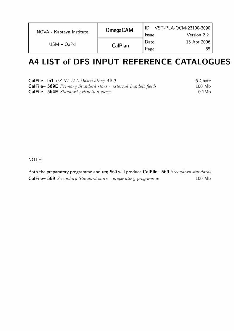
NOVA - Kapteyn Institute
USM – OaPd
OmegaCAM
CalPlan
ID VST-PLA-OCM-23100-3090
Issue Version 2.2
Date 13 Apr 2006
Page 85
A4 LIST of DFS INPUT REFERENCE CATALOGUES
CalFile– in1 US-NAVAL Observatory A2.0 6 GbyteCalFile– 569E Primary Standard stars - external Landolt fields 100 MbCalFile– 564E Standard extinction curve 0.1Mb
NOTE:
Both the preparatory programme and req.569 will produce CalFile– 569 Secondary standards.
CalFile– 569 Secondary Standard stars - preparatory programme 100 Mb
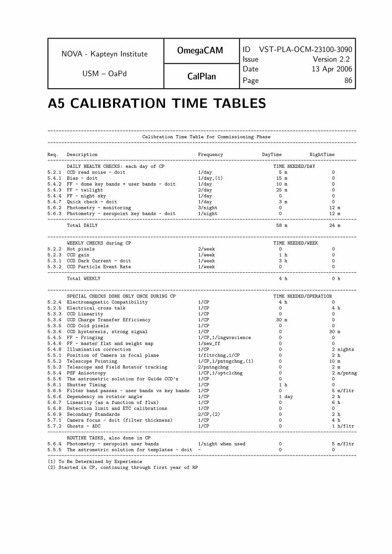
NOVA - Kapteyn Institute
USM – OaPd
OmegaCAM
CalPlan
ID VST-PLA-OCM-23100-3090Issue Version 2.2Date 13 Apr 2006
Page 86
A5 CALIBRATION TIME TABLES
---------------------------------------------------------------------------------------------------------------Calibration Time Table for Commissioning Phase
---------------------------------------------------------------------------------------------------------------
Req. Description Frequency DayTime NightTime---------------------------------------------------------------------------------------------------------------
DAILY HEALTH CHECKS: each day of CP TIME NEEDED/DAY5.2.1 CCD read noise - doit 1/day 5 m 05.4.1 Bias - doit 1/day,(1) 15 m 05.4.2 FF - dome key bands + user bands - doit 1/day 10 m 05.4.3 FF - twilight 2/day 25 m 05.4.4 FF - night sky 1/day 0 05.4.7 Quick check - doit 1/day 3 m 05.6.2 Photometry - monitoring 3/night 0 12 m5.6.3 Photometry - zeropoint key bands - doit 1/night 0 12 m---------------------------------------------------------------------------------------------------------------
Total DAILY 58 m 24 m
---------------------------------------------------------------------------------------------------------------WEEKLY CHECKS during CP TIME NEEDED/WEEK
5.2.2 Hot pixels 2/week 0 05.2.3 CCD gain 1/week 1 h 05.3.1 CCD Dark Current - doit 1/week 3 h 05.3.2 CCD Particle Event Rate 1/week 0 0---------------------------------------------------------------------------------------------------------------
Total WEEKLY 4 h 0 h
---------------------------------------------------------------------------------------------------------------SPECIAL CHECKS DONE ONLY ONCE DURING CP TIME NEEDED/OPERATION
5.2.4 Electromagnetic Compatibility 1/CP 4 h 05.2.5 Electrical cross talk 1/CP 0 4 h5.3.3 CCD Linearity 1/CP 0 05.3.4 CCD Charge Transfer Efficiency 1/CP 30 m 05.3.5 CCD Cold pixels 1/CP 0 05.3.6 CCD hysteresis, strong signal 1/CP 0 30 m5.4.5 FF - Fringing 1/CP,1/lngwvscience 0 05.4.6 FF - master flat and weight map 1/new_ff 0 05.4.8 Illumination correction 1/CP 0 2 nights5.5.1 Position of Camera in focal plane 1/fltrchng,1/CP 0 2 h5.5.2 Telescope Pointing 1/CP,1/pntngchng,(1) 0 10 m5.5.3 Telescope and Field Rotator tracking 2/pntngchng 0 2 m5.5.4 PSF Anisotropy 1/CP,1/optclchng 0 2 m/pntng5.5.6 The astrometric solution for Guide CCD’s 1/CP 0 05.6.1 Shutter Timing 1/CP 1 h 05.6.5 Filter band passes - user bands vs key bands 1/CP 0 5 m/fltr5.6.6 Dependency on rotator angle 1/CP 1 day 2 h5.6.7 Linearity (as a function of flux) 1/CP 0 6 h5.6.8 Detection limit and ETC calibrations 1/CP 0 05.6.9 Secondary Standards 2/CP,(2) 0 2 h5.7.1 Camera focus - doit (filter thickness) 1/CP 0 4 h5.7.2 Ghosts - ADC 1/CP 0 1 h/fltr---------------------------------------------------------------------------------------------------------------
ROUTINE TASKS, also done in CP5.6.4 Photometry - zeropoint user bands 1/night when used 0 5 m/fltr5.5.5 The astrometric solution for templates - doit - 0 0---------------------------------------------------------------------------------------------------------------(1) To Be Determined by Experience(2) Started in CP, continuing through first year of RP

NOVA - Kapteyn Institute
USM – OaPd
OmegaCAM
CalPlan
ID VST-PLA-OCM-23100-3090
Issue Version 2.2
Date 13 Apr 2006
Page 87
{\begin{verbatim}---------------------------------------------------------------------------------------------------------------
Calibration Time Table for Routine PHASE for OPERATIONS AND MAINTENANCE---------------------------------------------------------------------------------------------------------------Req. Description Frequency DayTime NightTime---------------------------------------------------------------------------------------------------------------
DAILY CHECKS / also after each maintenance activity TIME NEEDED/DAY5.2.1 CCD read noise - doit 1/day 5 m 05.4.1 Bias - doit 1/day,(1) 15 m 05.4.2 FF - dome key bands + user bands - doit 1/day 10 m 05.4.3 FF - twilight 1/day 25 m 05.4.4 FF - night sky 1/day 0 05.4.5 FF - Fringing use fringed science data 0 05.4.6 FF - master flat and weight map use data for 5.4.2 and 5.4.3 0 05.4.7 Quick check - doit 1/day 3 m 05.6.2 Photometry - monitoring 3/night 0 12 min5.6.3 Photometry - zeropoint key bands - doit 1/night 0 12 min5.6.4 Photometry - zeropoint user bands 1/night 0 5 m/fltr---------------------------------------------------------------------------------------------------------------
Total daily 58 m 24 min---------------------------------------------------------------------------------------------------------------
WEEKLY CHECKS TIME NEEDED/WEEK5.2.2 Hot pixels 2/week 0 05.2.3 CCD gain 1/week 1 h 05.3.1 CCD Dark Current - doit 1/week 3 h 05.3.2 CCD Particle Event Rate 1/week 0 05.3.3 CCD Linearity 1/month 0 0---------------------------------------------------------------------------------------------------------------
Total weekly 4 h 0 h---------------------------------------------------------------------------------------------------------------
QUARTERLY - YEARLY CHECKS TIME NEEDED/OPERATION5.3.4 CCD Charge Transfer Efficiency 2/year 30 m 05.3.5 CCD Cold pixels 4/year 0 05.3.6 CCD hysteresis, strong signal - 0 05.4.8 Illumination correction- quick verification 1/month 0 30 m5.5.1 Position of Camera in focal plane 1/year,user supplied filter 0 2 h5.5.2 Telescope Pointing 1/year,1/pntngchng,(1) 0 10 m5.5.3 Telescope and Field Rotator tracking (1) 0 2 m5.5.4 PSF Anisotropy 4/year,1/optclchng 0 10 m5.2.4 Electromagnetic Compatibility 1/year,1/syschng,(1) 4 h 05.6.1 Shutter Timing 4/year,(1) 1 h 05.5.5 The astrometric solution for templates - doit - 0 05.5.6 The astrometric solution for Guide CCD’s - 0 05.6.5 Filter band passes - user bands vs key bands - 0 05.6.6 Dependency on angle ADC, rotator - 0 05.6.7 Linearity (as a function of flux) - 0 05.6.8 Detection limit and ETC calibrations - 0 05.6.9 secondary standards first year of operations 0 2 bright nights/month---------------------------------------------------------------------------------------------------------------(1) To Be Determined by Experience\end{verbatim}}
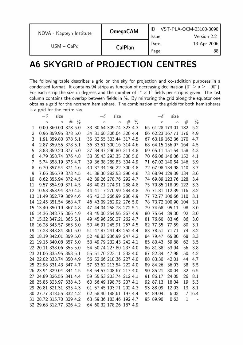
NOVA - Kapteyn Institute
USM – OaPd
OmegaCAM
CalPlan
ID VST-PLA-OCM-23100-3090
Issue Version 2.2
Date 13 Apr 2006
Page 88
A6 SKYGRID of PROJECTION CENTRES
The following table describes a grid on the sky for projection and co-addition purposes in acondensed format. It contains 94 strips as function of decreasing declination (0◦ ≥ δ ≥ −90◦).For each strip the size in degrees and the number of 1◦ × 1◦ fields per strip is given. The lastcolumn contains the overlap between fields in %. By mirroring the grid along the equator oneobtains a grid for the northern hemisphere. The combination of the grids for both hemispheresis a grid for the entire sky.
−δ size −δ size −δ size◦ ◦ # % ◦ ◦ # % ◦ ◦ # %
1 0.00 360.00 378 5.0 33 30.64 309.74 323 4.3 65 61.28 173.01 182 5.22 0.96 359.95 378 5.0 34 31.60 306.64 320 4.4 66 62.23 167.71 176 4.93 1.91 359.80 378 5.1 35 32.55 303.44 317 4.5 67 63.19 162.36 170 4.74 2.87 359.55 378 5.1 36 33.51 300.16 314 4.6 68 64.15 156.97 164 4.55 3.83 359.20 377 5.0 37 34.47 296.80 311 4.8 69 65.11 151.54 158 4.36 4.79 358.74 376 4.8 38 35.43 293.35 308 5.0 70 66.06 146.06 152 4.17 5.74 358.19 375 4.7 39 36.38 289.83 304 4.9 71 67.02 140.54 146 3.98 6.70 357.54 374 4.6 40 37.34 286.22 300 4.8 72 67.98 134.98 140 3.79 7.66 356.79 373 4.5 41 38.30 282.53 296 4.8 73 68.94 129.39 134 3.6
10 8.62 355.94 372 4.5 42 39.26 278.76 292 4.7 74 69.89 123.76 128 3.411 9.57 354.99 371 4.5 43 40.21 274.91 288 4.8 75 70.85 118.09 122 3.312 10.53 353.94 370 4.5 44 41.17 270.99 284 4.8 76 71.81 112.39 116 3.213 11.49 352.79 369 4.6 45 42.13 266.99 280 4.9 77 72.77 106.66 110 3.114 12.45 351.54 368 4.7 46 43.09 262.92 276 5.0 78 73.72 100.90 104 3.115 13.40 350.19 367 4.8 47 44.04 258.78 272 5.1 79 74.68 95.11 98 3.016 14.36 348.75 366 4.9 48 45.00 254.56 267 4.9 80 75.64 89.30 92 3.017 15.32 347.21 365 5.1 49 45.96 250.27 262 4.7 81 76.60 83.46 86 3.018 16.28 345.57 363 5.0 50 46.91 245.91 257 4.5 82 77.55 77.59 80 3.119 17.23 343.84 361 5.0 51 47.87 241.48 252 4.4 83 78.51 71.71 74 3.220 18.19 342.01 359 5.0 52 48.83 236.99 247 4.2 84 79.47 65.80 68 3.321 19.15 340.08 357 5.0 53 49.79 232.43 242 4.1 85 80.43 59.88 62 3.522 20.11 338.06 355 5.0 54 50.74 227.80 237 4.0 86 81.38 53.94 56 3.823 21.06 335.95 353 5.1 55 51.70 223.11 232 4.0 87 82.34 47.98 50 4.224 22.02 333.74 350 4.9 56 52.66 218.36 227 4.0 88 83.30 42.01 44 4.725 22.98 331.43 347 4.7 57 53.62 213.54 222 4.0 89 84.26 36.03 38 5.526 23.94 329.04 344 4.5 58 54.57 208.67 217 4.0 90 85.21 30.04 32 6.527 24.89 326.55 341 4.4 59 55.53 203.74 212 4.1 91 86.17 24.05 26 8.128 25.85 323.97 338 4.3 60 56.49 198.75 207 4.1 92 87.13 18.04 19 5.329 26.81 321.31 335 4.3 61 57.45 193.71 202 4.3 93 88.09 12.03 13 8.130 27.77 318.55 332 4.2 62 58.40 188.61 197 4.4 94 89.04 6.02 7 16.431 28.72 315.70 329 4.2 63 59.36 183.46 192 4.7 95 89.90 0.63 1 -32 29.68 312.77 326 4.2 64 60.32 178.26 187 4.9

NOVA - Kapteyn Institute
USM – OaPd
OmegaCAM
CalPlan
ID VST-PLA-OCM-23100-3090
Issue Version 2.2
Date 13 Apr 2006
Page 89
A7 CALIBRATION VERIFICATION MATRIX
5.2.1 Req.– Cat I: CCD read noise - doit . . . . . . . . . . . . . . . . . . . . . . . . . . . . . . . . . . . . . .⊔
Required accuracy, constraints:
Readout noise less than 5e−.Variation in readout noise w.r.t. reference value less than 0.5e−.
5.2.2 Req.– Cat I: Hot pixels . . . . . . . . . . . . . . . . . . . . . . . . . . . . . . . . . . . . . . . . . . . . . . . . . .⊔
Required accuracy, constraints:
Number of hot pixels to be determined by experience/lab values.The total number of bad pixels (hot pixels + cold pixels) is less than 80000 (checked inreq. 535 Cold pixelsDifference in number of hot pixels w.r.t. reference value, less than 100.
5.2.3 Req.– Cat I: CCD gain . . . . . . . . . . . . . . . . . . . . . . . . . . . . . . . . . . . . . . . . . . . . . . . . . .⊔
Required accuracy, constraints:
Accuracy: In units of e−/ADU, from lab values or found empirically. Variation in time lessthan 1%.
5.2.4 Req.– Cat III: Electromagnetic Compatibility . . . . . . . . . . . . . . . . . . . . . . . . . . . .⊔
Required accuracy, constraints:
Difference between read noise under operational conditions and the standard read noise mea-surement should be smaller than 20% for external and 10% for internal causes of interference.
5.2.5 Req.– Cat III: Electrical cross talk . . . . . . . . . . . . . . . . . . . . . . . . . . . . . . . . . . . . . . .⊔
Required accuracy, constraints:
10−5
5.3.1 Req.– Cat I: CCD Dark Current - doit . . . . . . . . . . . . . . . . . . . . . . . . . . . . . . . . . .⊔
Required accuracy, constraints:
Dark count rate should be less than the equivalent of 3 e−/pixel/hour in ADUs excluding badpixels.Accuracy of determining particle event rate 1 ADU/cm2/hour.Particle event rates should be identical for each chip.

NOVA - Kapteyn Institute
USM – OaPd
OmegaCAM
CalPlan
ID VST-PLA-OCM-23100-3090
Issue Version 2.2
Date 13 Apr 2006
Page 90
5.3.2 Req.– Cat I: CCD Particle Event Rate . . . . . . . . . . . . . . . . . . . . . . . . . . . . . . . . . .⊔
Required accuracy, constraints:
better than 1 ADU/cm2/hour
5.3.3 Req.– Cat I: CCD Linearity . . . . . . . . . . . . . . . . . . . . . . . . . . . . . . . . . . . . . . . . . . . . .⊔
Required accuracy, constraints:
better than 1% on the photometric scale
5.3.4 Req.– Cat III: CCD Charge Transfer Efficiency . . . . . . . . . . . . . . . . . . . . . . . . . .⊔
Required accuracy, constraints:
CTE > 0.999995 per parallel or serial shift.
5.3.5 Req.– Cat I: CCD Cold Pixels . . . . . . . . . . . . . . . . . . . . . . . . . . . . . . . . . . . . . . . . . . .⊔
Required accuracy, constraints:
Quality Check: Number of hot pixels to be determined by experience/lab values. The totalnumber of bad pixels (hot pixels + cold pixels) is less than 80000. Difference in number ofcold pixels w.r.t. reference version less than 100.
5.3.6 Req.– Cat III: CCD Hysteresis, strong signal . . . . . . . . . . . . . . . . . . . . . . . . . . . .⊔
5.4.1 Req.– Cat I: Bias - doit . . . . . . . . . . . . . . . . . . . . . . . . . . . . . . . . . . . . . . . . . . . . . . . . .⊔
Required accuracy, constraints:
The required accuracy per pixel in the master bias frame is “nominal read-outnoise/√
10”.
For the quality check: Since an overscan correction is performed, the deviation of the meanlevel of master bias (bias level) from zero, should be less than TBD.
5.4.2 Req.– Cat I: Flat-field - dome key bands + user bands - doit . . . . . . . . . . . . .⊔
Required accuracy, constraints:
Accurately measuring pixel-to-pixel gain variations as small as 1%. Re-insertion of the filtershall not alter the flat field stucture by more than 0.3% (rms, measured over the full detectorarea).
5.4.3 Req.– Cat I: Flat-field - twilight . . . . . . . . . . . . . . . . . . . . . . . . . . . . . . . . . . . . . . . . .⊔
Required accuracy, constraints:
Mean levels should be approximately 20000 ADU.

NOVA - Kapteyn Institute
USM – OaPd
OmegaCAM
CalPlan
ID VST-PLA-OCM-23100-3090
Issue Version 2.2
Date 13 Apr 2006
Page 91
5.4.4 Req.– Cat I: Flat-field - night sky . . . . . . . . . . . . . . . . . . . . . . . . . . . . . . . . . . . . . . . .⊔
Required accuracy, constraints:
This procedure would benefit from a prior detection and masking of bright objects. If no masksof bright objects are available, then a minimum of 15 frames should be included.
5.4.5 Req.– Cat I: Flat-field - fringing . . . . . . . . . . . . . . . . . . . . . . . . . . . . . . . . . . . . . . . . .⊔
5.4.6 Req.– Cat I: Flat-field - master flat . . . . . . . . . . . . . . . . . . . . . . . . . . . . . . . . . . . . . .⊔
5.4.7 Req.– Cat I: Quick detector responsivity check-doit . . . . . . . . . . . . . . . . . . . . . . .⊔
Required accuracy, constraints:
1%
5.4.8 Req.– Cat II: Illumination correction . . . . . . . . . . . . . . . . . . . . . . . . . . . . . . . . . . . .⊔
Required accuracy, constraints:
better than 1% for the amplitude over a single CCD.
5.5.1 Req.– Cat III: Position of Camera in focal plane . . . . . . . . . . . . . . . . . . . . . . . . .⊔
Required accuracy, constraints:
Internal precision: 0.3 pixel. External precision limited by reference catalog
5.5.2 Req.– Cat III: Telescope Pointing and offsetting . . . . . . . . . . . . . . . . . . . . . . . . .⊔
Required accuracy, constraints:
1 arc second
5.5.3 Req.– Cat III: Telescope and Field Rotator tracking . . . . . . . . . . . . . . . . . . . . . .⊔
Required accuracy, constraints:
VST requirements:free tracking better than 0.2 arcsec r.m.s.autoguiding tracking better 0.05 arcsec
5.5.4 Req.– Cat III: PSF Anisotropy . . . . . . . . . . . . . . . . . . . . . . . . . . . . . . . . . . . . . . . . . .⊔
Required accuracy, constraints:
better than 1%

NOVA - Kapteyn Institute
USM – OaPd
OmegaCAM
CalPlan
ID VST-PLA-OCM-23100-3090
Issue Version 2.2
Date 13 Apr 2006
Page 92
5.5.5 Req.– Cat I: The astrometric solution for templates - doit -see 6.3.4 . . . . . .⊔
5.5.6 Req.– Cat III: The astrometric solution for Guide CCD’s . . . . . . . . . . . . . . . .⊔
Required accuracy, constraints:
1 arcsec rms for the accuracy with respect to the external standard;
External precision is driven by the position reference catalog. This is in the case of the USNO-A2 catalog of the order 0.3” with possible systematic excursions to 1”.
5.6.1 Req.– Cat III: Shutter Timing . . . . . . . . . . . . . . . . . . . . . . . . . . . . . . . . . . . . . . . . . . .⊔
Required accuracy, constraints:
Timing error less than 0.2%.
5.6.2 Req.– Cat I: Photometric Calibration - monitoring . . . . . . . . . . . . . . . . . . . . . .⊔
Required accuracy, constraints:
all photometry better than 1-2% on the photometric scale.
5.6.3 Req.– Cat I: Photometric Calibration - zeropoint keybands - doit . . . . . . . . .⊔
Required accuracy, constraints:
1% on the photometric scale
5.6.4 Req.– Cat I: Photometric Calibration - zeropoint user bands . . . . . . . . . . . . . .⊔
Required accuracy, constraints:
2% on the photometric scale for broad bands and 5% for narrow band filters.
5.6.5 Req.– Cat I: Filter band passes - user bands vs key bands . . . . . . . . . . . . . . . . .⊔
Required accuracy, constraints:
10% on the photometric scale (formal spec) and 2% (goal) for broad band filters1% for composite -> key
5.6.6 Req.– Cat III: Dependency on angle - ADC, rotator/reproducibility . . . . . . .⊔
Required accuracy, constraints:
1% on the photometric scale
5.6.7 Req.– Cat III: Linearity (as a function of flux) . . . . . . . . . . . . . . . . . . . . . . . . . .⊔
Required accuracy, constraints:
Better than 1% on the photometric scale

NOVA - Kapteyn Institute
USM – OaPd
OmegaCAM
CalPlan
ID VST-PLA-OCM-23100-3090
Issue Version 2.2
Date 13 Apr 2006
Page 93
5.6.8 Req.– Cat III: Detection limit and ETC calibrations . . . . . . . . . . . . . . . . . . . . .⊔
Required accuracy, constraints:
10 % in detection limit
5.6.9 Req.– Cat I: Secondary Standards . . . . . . . . . . . . . . . . . . . . . . . . . . . . . . . . . . . . . . .⊔
Required accuracy, constraints:
0.02 mag in individual secondary standards stars. The sources in CalFile– 569 should cover aFoV of approximately 1.2 square degree.
5.7.1 Req.– Cat III: Camera focus/tilt . . . . . . . . . . . . . . . . . . . . . . . . . . . . . . . . . . . . . . . .⊔
5.7.2 Req.– Cat III: Ghosts - ADC . . . . . . . . . . . . . . . . . . . . . . . . . . . . . . . . . . . . . . . . . . .⊔
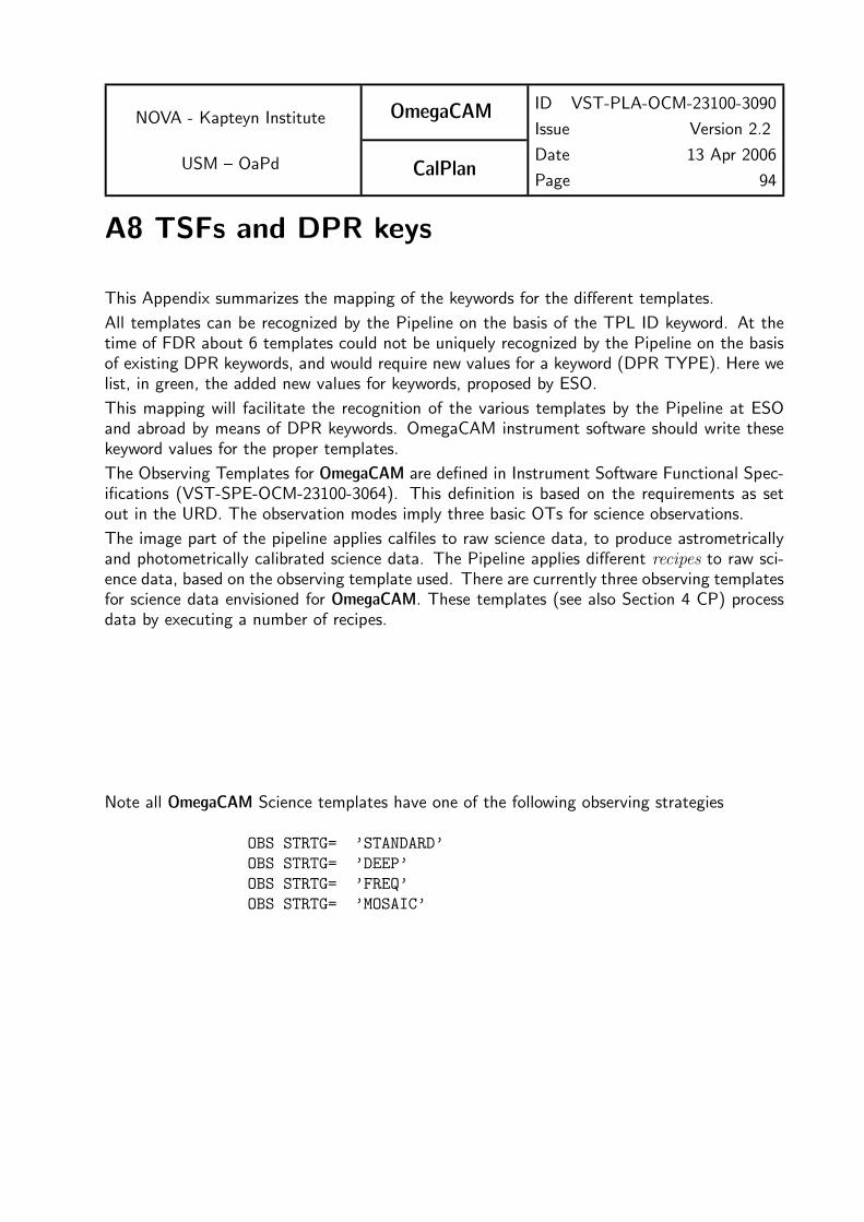
NOVA - Kapteyn Institute
USM – OaPd
OmegaCAM
CalPlan
ID VST-PLA-OCM-23100-3090
Issue Version 2.2
Date 13 Apr 2006
Page 94
A8 TSFs and DPR keys
This Appendix summarizes the mapping of the keywords for the different templates.
All templates can be recognized by the Pipeline on the basis of the TPL ID keyword. At thetime of FDR about 6 templates could not be uniquely recognized by the Pipeline on the basisof existing DPR keywords, and would require new values for a keyword (DPR TYPE). Here welist, in green, the added new values for keywords, proposed by ESO.
This mapping will facilitate the recognition of the various templates by the Pipeline at ESOand abroad by means of DPR keywords. OmegaCAM instrument software should write thesekeyword values for the proper templates.
The Observing Templates for OmegaCAM are defined in Instrument Software Functional Spec-ifications (VST-SPE-OCM-23100-3064). This definition is based on the requirements as setout in the URD. The observation modes imply three basic OTs for science observations.
The image part of the pipeline applies calfiles to raw science data, to produce astrometricallyand photometrically calibrated science data. The Pipeline applies different recipes to raw sci-ence data, based on the observing template used. There are currently three observing templatesfor science data envisioned for OmegaCAM. These templates (see also Section 4 CP) processdata by executing a number of recipes.
Note all OmegaCAM Science templates have one of the following observing strategies
OBS STRTG= ’STANDARD’
OBS STRTG= ’DEEP’
OBS STRTG= ’FREQ’
OBS STRTG= ’MOSAIC’

NOVA - Kapteyn Institute
USM – OaPd
OmegaCAM
CalPlan
ID VST-PLA-OCM-23100-3090
Issue Version 2.2
Date 13 Apr 2006
Page 95
Science templates
• TSF– OCAM img obs stare N=:Observe N (default 1) exposures with one fixed pointing position.Recipe– Split, Recipe– Reduce
TPL ID = OCAM_img_obs_stare
TPL NEXP = N
DPR CATG = ’SCIENCE’
DPR TYPE = ’OBJECT’
DPR TECH = ’IMAGE, DIRECT’
• TSF– OCAM img obs jitter N=:Observe with N pointings (≥ 2) in the sky, with small offsets (≈ 5 pixels) betweenexposures.Recipe– Split, Recipe– Reduce, Recipe– Coadd
TPL ID = OCAM_img_obs_jitter
TPL NEXP = N
DPR CATG = ’SCIENCE’
DPR TYPE = ’OBJECT’
DPR TECH = ’IMAGE, JITTER’
• TSF– OCAM img obs dither N=:Observe with N pointings (default 5) in the sky, with offsets > maximum gap betweendetectors (> 390 pixels) between exposures.Recipe– Split, Recipe– Reduce, Recipe– Coadd
TPL ID = OCAM_img_obs_dither
TPL NEXP = N
DPR CATG = ’SCIENCE’
DPR TYPE = ’OBJECT’
DPR TECH = ’IMAGE, DITHER’
+ TSF– OCAM img obs offset N=:Observe with N pointings in the sky, with user-defined offsets between exposures.Recipe– Split, Recipe– Reduce, Recipe– Coadd
TPL ID = OCAM_img_obs_offset
TPL NEXP = N
DPR CATG = ’SCIENCE’
DPR TYPE = ’OBJECT’
DPR TECH = ’IMAGE, OFFSET’

NOVA - Kapteyn Institute
USM – OaPd
OmegaCAM
CalPlan
ID VST-PLA-OCM-23100-3090
Issue Version 2.2
Date 13 Apr 2006
Page 96
The following calibration Templates are used.
• TSF– OCAM img cal bias(N=)Acquire N bias exposures, with opaque filter in optical path and shutter closed.Recipe– Biasdone daily in the beginning, later at much lower frequency
TPL ID = OCAM_img_cal_bias
TPL NEXP = N
DPR CATG = ’CALIB’
DPR TYPE = ’BIAS’
DPR TECH = ’IMAGE’
OBS STRTG= ’STANDARD’
- TSF– OCAM img cal readnoiseBias exposures with N = 2Recipe– Read NoiseDone daily throughout operations- daily healthcheck.
TPL ID = OCAM_img_cal_readnoise
TPL NEXP = 2
DPR CATG = ’CALIB’
DPR TYPE = ’BIAS, READNOISE’
DPR TECH = ’IMAGE’
OBS STRTG= ’STANDARD’
• TSF– OCAM img cal dark(N=)Acquire N dark exposures, with opaque filter in optical path and shutter closed.Recipe– Dark Current
TPL ID = OCAM_img_cal_dark
TPL NEXP = N
DPR CATG = ’CALIB’
DPR TYPE = ’DARK’
DPR TECH = ’IMAGE’
OBS STRTG= ’STANDARD’

NOVA - Kapteyn Institute
USM – OaPd
OmegaCAM
CalPlan
ID VST-PLA-OCM-23100-3090
Issue Version 2.2
Date 13 Apr 2006
Page 97
Flat Fields
• TSF– OCAM img cal skyflatAcquire N sky (twilight) flats, through a given filter.Recipe– Twilight Flat
TPL ID = OCAM_img_cal_skyflat
TPL NEXP = N
DPR CATG = ’CALIB’
DPR TYPE = ’FLAT, SKY’
DPR TECH = ’IMAGE, JITTER’
OBS STRTG= ’STANDARD’
• TSF– OCAM img cal domeflat(N=)Acquire N dome flats. Telescope is preset to point towards the flat-field screen (withouttracking), lamps must be switched on.Recipe– Dome Flatonce/week for each filter
TPL ID = OCAM_img_cal_domeflat
TPL NEXP = N
DPR CATG = ’CALIB’
DPR TYPE = ’FLAT, DOME’
DPR TECH = ’IMAGE’
OBS STRTG= ’STANDARD’
- TSF– OCAM img cal gainDomeflat exposures with texp = 2, 60, 50, 4, ..., 4, 50, 60, 2 r’ filterRecipe– Gainonce per week one filter (later perhaps once per month)
TPL ID = OCAM_img_cal_gain
TPL NEXP = 20
DPR CATG = ’CALIB’
DPR TYPE = ’FLAT, DOME, DETGAIN’
DPR TECH = ’IMAGE’
OBS STRTG= ’STANDARD’
- TSF– OCAM img cal quickDaily Health check throughout operations. Domeflat exposure with N = 1 ,filter=composite, tint fixedRecipe– Quick Check
TPL ID = OCAM_img_cal_quick
TPL NEXP = 1
DPR CATG = ’CALIB’
DPR TYPE = ’FLAT, DOME, LIFETEST’
DPR TECH = ’IMAGE’

NOVA - Kapteyn Institute
USM – OaPd
OmegaCAM
CalPlan
ID VST-PLA-OCM-23100-3090
Issue Version 2.2
Date 13 Apr 2006
Page 98
OBS STRTG= ’STANDARD’
- TSF– OCAM img cal shutterDomeflat exposures with texp = 10, 0.1, 0.1, 10Once per three monthRecipe– Shutter Delay
TPL ID = OCAM_img_cal_shutter
TPL NEXP = 4
DPR CATG = ’CALIB’
DPR TYPE = ’FLAT, DOME, SHUTTERTEST’
DPR TECH = ’IMAGE’
OBS STRTG= ’STANDARD’
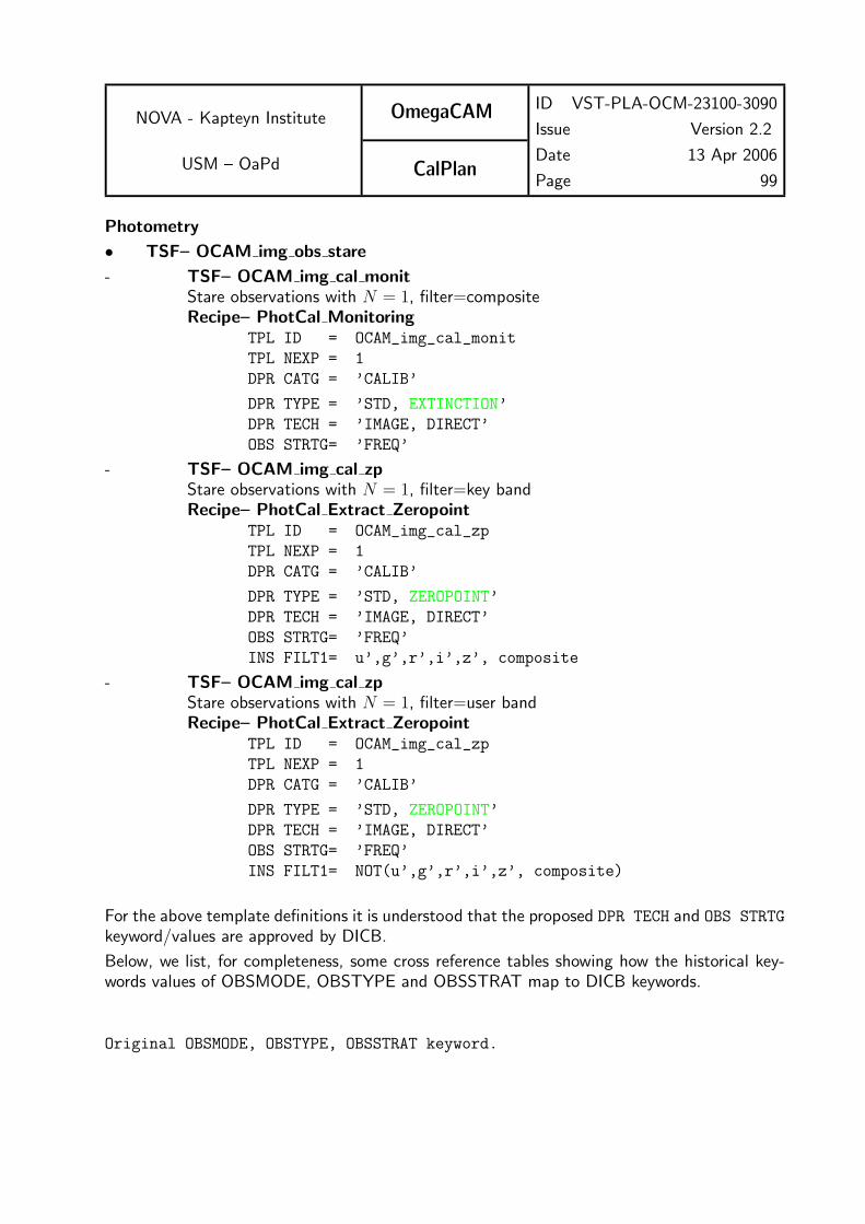
NOVA - Kapteyn Institute
USM – OaPd
OmegaCAM
CalPlan
ID VST-PLA-OCM-23100-3090
Issue Version 2.2
Date 13 Apr 2006
Page 99
Photometry
• TSF– OCAM img obs stare
- TSF– OCAM img cal monitStare observations with N = 1, filter=compositeRecipe– PhotCal Monitoring
TPL ID = OCAM_img_cal_monit
TPL NEXP = 1
DPR CATG = ’CALIB’
DPR TYPE = ’STD, EXTINCTION’
DPR TECH = ’IMAGE, DIRECT’
OBS STRTG= ’FREQ’
- TSF– OCAM img cal zpStare observations with N = 1, filter=key bandRecipe– PhotCal Extract Zeropoint
TPL ID = OCAM_img_cal_zp
TPL NEXP = 1
DPR CATG = ’CALIB’
DPR TYPE = ’STD, ZEROPOINT’
DPR TECH = ’IMAGE, DIRECT’
OBS STRTG= ’FREQ’
INS FILT1= u’,g’,r’,i’,z’, composite
- TSF– OCAM img cal zpStare observations with N = 1, filter=user bandRecipe– PhotCal Extract Zeropoint
TPL ID = OCAM_img_cal_zp
TPL NEXP = 1
DPR CATG = ’CALIB’
DPR TYPE = ’STD, ZEROPOINT’
DPR TECH = ’IMAGE, DIRECT’
OBS STRTG= ’FREQ’
INS FILT1= NOT(u’,g’,r’,i’,z’, composite)
For the above template definitions it is understood that the proposed DPR TECH and OBS STRTG
keyword/values are approved by DICB.
Below, we list, for completeness, some cross reference tables showing how the historical key-words values of OBSMODE, OBSTYPE and OBSSTRAT map to DICB keywords.
Original OBSMODE, OBSTYPE, OBSSTRAT keyword.

NOVA - Kapteyn Institute
USM – OaPd
OmegaCAM
CalPlan
ID VST-PLA-OCM-23100-3090
Issue Version 2.2
Date 13 Apr 2006
Page 100
Keyword as recommended by DICB.
Terminology used in the User Manual.
Historical DICB Keyword User Manual
OBSMODE DPR TECH Offsetting Mode
---------------------------------------------------
STARE IMAGE,DIRECT STARE
DITHER IMAGE,DITHER DITHER
JITTER IMAGE,JITTER JITTER
SSO IMAGE,SSO SOLARSYSTEM
IMAGE,OFFSET *)
MOSAIC IMAGE,MOSAIC *)
*) Not mentioned in the User Manual in section 3.1.1 Offsetting Mode.
Historical DICB Keyword
OBSTYPE DPR TYPE
-----------------------------
BIAS BIAS
DARK DARK
DFLAT FLAT,DOME
TFLAT FLAT,SKY
OBS OBJECT
OBS STD
OBSTYPE is absent from the User Manual.
New values for DICB keyword DPR TYPE
------------------------------------
READNOISE
DETGAIN
LIFETEST
SHUTTERTEST
EXTINCTION
ZEROPOINT
Historical DICB Keyword User Manual
OBSSTRAT OBS STRTG Observing Strategy
------------------------------------------------

NOVA - Kapteyn Institute
USM – OaPd
OmegaCAM
CalPlan
ID VST-PLA-OCM-23100-3090
Issue Version 2.2
Date 13 Apr 2006
Page 101
STANDARD STANDARD STANDARD
DEEP DEEP DEEP
FREQ FREQ FREQ
MOSAIC MOSAIC MOSAIC