OMEGA-IFx for UML/SysML v2.0 Profile and Toolset User - IRIT
43
OMEGA-IFx for UML/SysML v2.0 Profile and Toolset User Manual Document version : 1.1b Date : 15/05/13
Transcript of OMEGA-IFx for UML/SysML v2.0 Profile and Toolset User - IRIT

OMEGA-IFx for UML/SysML v2.0 Profile and Toolset User Manual
Document version : 1.1b
Date : 15/05/13

OMEGA-IFx for UML/SysML v2.0
Profile and Toolset User Manual
Version : 1.1b Date : 15/05/13
2
Table of Contents REFERENCE DOCUMENTS......................................................................................................................................................5
1 DOCUMENT STRUCTURE .................................................................................................................................................6
2 OMEGA2 PROFILE ..............................................................................................................................................................6
2.1 COVERED UML/SYSML SUBSET ........................................................................................................................................6 2.2 OVERVIEW OF THE EXECUTION SEMANTICS........................................................................................................................7
2.2.1 Execution model..........................................................................................................................................................7 2.2.1.1 Activity groups and concurrency..............................................................................................................................................7 2.2.1.2 Operations, signals and state machines ....................................................................................................................................7
2.2.2 Observers ....................................................................................................................................................................8 2.3 EXTENSIONS AND WELL-FORMEDNESS RULES DEFINED IN OMEGA2 ...............................................................................8
2.3.1 Simple class models (Block Definition Diagrams) .....................................................................................................8 2.3.2 Composite structures (Internal Block Diagrams).......................................................................................................9
2.3.2.1 Simple composite structures .....................................................................................................................................................9 2.3.2.2 Routing composite structures .................................................................................................................................................11 2.3.2.3 Default port behavior and user-defined port behavior............................................................................................................16 2.3.2.4 Impact of composite structures on the action language..........................................................................................................18
2.3.3 Behaviour..................................................................................................................................................................19 2.3.4 Extensions and rules for the concurrency model......................................................................................................19
2.3.4.1 Active and passive classes ......................................................................................................................................................19 2.3.4.2 Protected classes .....................................................................................................................................................................20 2.3.4.3 Concurrency and composite structures...................................................................................................................................20
2.3.5 Extensions and rules for object and system initialization.........................................................................................21 2.3.6 Extensions and rules for observers ...........................................................................................................................22 2.3.7 OMEGA action language syntax changes ................................................................................................................22
3 THE SOFTWARE PACKAGE ...........................................................................................................................................24
3.1 WHAT DO YOU NEED IN ORDER TO RUN IFX-OMEGA......................................................................................................24 3.2 OTHER AVAILABLE COMPONENTS.....................................................................................................................................24 3.3 PLATFORM REQUIREMENTS ..............................................................................................................................................25 3.4 IFX INSTALLATION INSTRUCTIONS ...................................................................................................................................25 3.5 IFX-OMEGA INSTALLATION INSTRUCTIONS ...................................................................................................................26
4 OMEGA2 MODELING TUTORIAL (WITH IBM RHAPSODY) .................................................................................27
4.1 ATM PROBLEM STATEMENT.............................................................................................................................................27 4.2 BASIC MODELING IN OMEGA2 ........................................................................................................................................27 4.3 COMMUNICATION MODELING ...........................................................................................................................................29 4.4 BEHAVIOR MODELING.......................................................................................................................................................31 4.5 PROPERTY MODELING.......................................................................................................................................................32
5 HOW TO USE THE IFX2 TOOLSET ...............................................................................................................................34

OMEGA-IFx for UML/SysML v2.0
Profile and Toolset User Manual
Version : 1.1b Date : 15/05/13
3
5.1 OVERALL ARCHITECTURE.................................................................................................................................................34 5.2 OVERALL WORKFLOW ......................................................................................................................................................34 5.3 EXPORT OMEGA2 MODEL AS XMI 2.0............................................................................................................................35 5.4 UML2IF : COMPILING THE OMEGA2 MODEL ....................................................................................................................36 5.5 DFA : AUTOMATIC ABSTRACTIONS ....................................................................................................................................37 5.6 IF2GEN : COMPILING THE IF MODEL ..................................................................................................................................37 5.7 AUTOMATIC VERIFICATION (MODEL.EXE) ........................................................................................................................38 5.8 IF2GUI: INTERACTIVE SIMULATION ...................................................................................................................................38
5.8.1 Running principle .....................................................................................................................................................38 5.8.2 Main components of the interface.............................................................................................................................38 5.8.3 Simulation actions.....................................................................................................................................................39 5.8.4 Structured views........................................................................................................................................................39 5.8.5 Stop conditions..........................................................................................................................................................40 5.8.6 Other functions .........................................................................................................................................................40
5.9 USING THE EXAMPLES ......................................................................................................................................................40 6 FREQUENT PROBLEMS AND SOLUTIONS.................................................................................................................42
6.1 MODELING........................................................................................................................................................................42 6.2 SIMULATION: ....................................................................................................................................................................42 6.3 VERIFICATION: .................................................................................................................................................................42

OMEGA-IFx for UML/SysML v2.0
Profile and Toolset User Manual
Version : 1.1b Date : 15/05/13
4
Table of Figures Figure 1. Association used as type for a link.................................................................................................9 Figure 2.Example of simple composite structure ........................................................................................10 Figure 3. Class structure equivalent to the composite structure in Figure 2................................................10 Figure 4. Interface definition .......................................................................................................................11 Figure 5. Interface I defines port type .........................................................................................................11 Figure 6. Port declaration with type I and required interface J (not supported in OMEGA2) ....................12 Figure 7. Delegation links in OMEGA2......................................................................................................14 Figure 8. Assembly links in OMEGA2 .......................................................................................................16 Figure 9. Simple port behavior ....................................................................................................................17 Figure 10. Non-default port behavior ..........................................................................................................17 Figure 11. Associating behaviour to ports in Rhapsody..............................................................................18 Figure 12. Definition of a protected class....................................................................................................20 Figure 13. Forbidden composite structure ...................................................................................................21 Figure 14. Sound composite structure formed of active/protected objects .................................................21 Figure 15. OMEGA UML 1.x syntax for Signal input (deprecated)...........................................................23 Figure 16. OMEGA2 syntax for Signal input..............................................................................................23 Figure 17. Active class definition................................................................................................................28 Figure 18. “Root” stereotype .......................................................................................................................28 Figure 19. Ports and links model .................................................................................................................29 Figure 20. “portType” stereotype ................................................................................................................29 Figure 21. Reversed port example ...............................................................................................................30 Figure 22. Behavior port example ...............................................................................................................30 Figure 23. Signal parameters accessed through reception...........................................................................31 Figure 24. Console’s statechart....................................................................................................................32 Figure 25. A property of ATM formalized by an observer .........................................................................33 Figure 26. IFx toolset architecture...............................................................................................................34 Figure 27. IFx2 workflow............................................................................................................................35 Figure 28. Rhapsody XMI export ................................................................................................................36 Figure 29. XMI export options ....................................................................................................................36 Figure 30. if2gui runtime architecture .........................................................................................................38 Figure 31. if2gui interface ...........................................................................................................................39

OMEGA-IFx for UML/SysML v2.0
Profile and Toolset User Manual
Version : 1.1b Date : 15/05/13
5
Reference Documents [1] UML 2.2 Superstructure Specification. OMG document formal//09-02-02.
http://www.omg.org/spec/UML/2.2/Superstructure
[2] A. Burns et A. Wellings, Real-Time Systems and Programming Languages. Addison Wesley; 3 edition, 2001.
[3] Rhapsody 7.4 User Manual. IBM, 2008. [4] OMEGA syntax for users. OMEGA project deliverable D2.2.2 annex 1.
[5] I. Ober, S. Graf and I. Ober. Validating timed UML models by simulation and verification. International Journal of Software Tools for Technology Transfer (STTT), Volume 8, Number 2, pages 128-145, April, 2006. Springer Verlag.
OMEGA-IFx for UML/SysML v2.0
Profile and Toolset User Manual
Version : 1.1b Date : 15/05/13
6
1 Document structure
This user guide is organized as follows:
• Section 2 provides a description of the OMEGA2 profile, including the covered UML/SysML subset, an overview of the execution semantics, and the list of extensions and well formedness rules defined by the profile.
• Section 3 describes the contents of the software package, the system requirements and the installation instructions.
• Section 4 explains the modeling constructs available in the OMEGA 2.0 UML/SysML profile on the basis of an example.
• Section 5 describes the workflow with the tool and its main functionalities.
• Section 6 lists the most frequently encountered problems and their possible solutions.
2 OMEGA2 Profile
The purpose of this section is to define the general principles of the new OMEGA profile for UML 2.2 / SysML 1.1 (henceforth called OMEGA2). It describes:
- the subset of UML 2.2 / SysML covered by the profile,
- the general structure to which OMEGA2 models have to conform,
- the syntactic extensions in the form of stereotypes
- the informal operational semantics for the covered constructs (when differing from the standard semantics prescribed by the UML 2.2 or SysML 1.1 standard)
The following text applies to both UML and SysML. To simplify the presentation, we sometimes refer only to the UML concepts (e.g., classes), but the support for the corresponding SysML concepts (e.g., blocks) is implicit.
2.1 Covered UML/SysML subset
OMEGA2 is an executable UML/SysML profile dedicated to the formal specification and validation of critical real-time systems. It is based on a subset of UML 2.2 / SysML 1.1 containing the main constructs for defining:
1. System structure:
a. Class diagrams (UML): classes and their relationships, interfaces, basic types, signals, composite structures (ports, parts, connectors)
b. Block diagrams (SysML):
o Block Definition Diagram (BDD): blocks and their relationships (ReferenceAssociation, PartAssociation, Generalization), interfaces, basic types, signals

OMEGA-IFx for UML/SysML v2.0
Profile and Toolset User Manual
Version : 1.1b Date : 15/05/13
7
o Internal Block Diagram (IBD): Parts, Standard Ports, Connectors
2. Class/Block behavior
a. State machines (excluding: history states, entry point, exit point, junction, state activities)
b. Actions: the profile defines a concrete syntax for UML 2.2 actions. This syntax is used for example to define operation bodies and transition effects in state machines. The textual action language is compatible with the UML 2.2 action metamodel and implements its main elements: object creation and destruction, operation calls, expression evaluation, variable assignment, signal output, return action as well as control flow structuring statements (conditionals and loops, which in UML are part of the activity metamodel).
OMEGA2 models can be edited with any UML 2.2 or SysML 1.1 editor supporting profiling and export in the standard XMI 2.0 format.
2.2 Overview of the execution semantics
A particular executable semantics is defined for these modeling constructs by specializing the semantic variation points left open by the UML or SysML standard. In addition, OMEGA2 provides means for formalizing the properties of the system, in particular timing properties, in the form of observers. This section overviews these notions, more details are provided in [4],[5].
2.2.1 Execution model 2.2.1.1 Activity groups and concurrency
There are two kinds of classes: active and passive ones. At execution, each instance of an active class defines a concurrency unit called activity group. Each instance of a passive class belongs to exactly one activity group, the one of the instance that has created it.
Apart from defining the partition of the system into activity groups, there is no difference between how active and passive classes (and instances) are defined and handled. Both kinds of classes are defined by their attributes, relationships, operations and state machine, and their operational semantics is identical.
Different activity groups are considered as concurrent, and each activity group treats external requests (all signals and operation calls from outside the group) one by one in a run-to-completion fashion. During a step, the above-mentioned external requests are deferred and stored in the activity groups' request queue as long as the activity group is not stable.
An activity group is stable when all its objects are. An object is stable if it has no enabled spontaneous transition (that is a transition which is guarded only by a boolean condition and not triggered by an event) and no pending operation call from inside its group. The motivation for making activity groups working in run-to-completion steps is to be able to consider such a step as atomic from the point of view of the environment of the group. This interpretation of activity groups implies that every activity group has a single control thread, and the atomicity of steps allows preemptive scheduling at run-time.
2.2.1.2 Operations, signals and state machines Operation calls are synchronous: the caller (and its group) is blocked in a suspended state until the completion of the call. The UML model distinguishes syntactically between two kinds of operations: triggered and primitive ones. The body of triggered operations is described directly in the state machine of a class: the operation call is seen as a special kind of transition trigger. Triggered operations differ from asynchronous signals in that they may have a return value. Primitive operations are closer to methods in usual object oriented programming language. They have a body described by an action. Their handling is more delicate since they may be overridden in the inheritance hierarchy and they are dynamically bound, like in all object-oriented models. When a call for a primitive operation is sent to an object, the
OMEGA-IFx for UML/SysML v2.0
Profile and Toolset User Manual
Version : 1.1b Date : 15/05/13
8
appropriate operation implementation with respect to the actual type of the called object in the inheritance hierarchy has to be executed.
With respect to call initiation, when an object having the control in its activity group calls an operation on an(other) object from the same group, the call is handled immediately (i.e. on the same control thread), like in usual programming languages. Notice that in case of triggered operation calls, the dynamic call graph should be acyclic, since an object that is already waiting for the termination of a call --- made from within a statemachine transition --- is in a suspended state in which it is not able to handle any new calls.
Calls received from other activity groups are, independently of the type of operation call, queued by the receiving group and handled in a subsequent run-to-completion step. Signals are always put in the target object's group queue for handling in a later run-to-completion step, regardless of whether the target is in the same group as the sender or not. This choice is made in order to be able to distinguish triggering an action within the same step (an operation call) and triggering an action in a later step (signal trigger). It has also the effect that concurrency within an activity group cannot be created by sending asynchronous signals.
2.2.2 Observers For specifying and verifying dynamic properties of models, OMEGA uses the notion of observers. Observers are special classes/blocks monitoring run-time state and events. Observers are defined by classes / blocks stereotyped with <<observer>>. They may have local memory (attributes) and a state machine describes their behaviour. Sates are classified as <<error>> states to express properties and hypotheses.
The main issue in defining observers is the choice of events which trigger their transitions, and which must include specific UML event types. The IFx version of OMEGA uses the following event types:
- Events related to signal exchange: send, receivesignal, acceptsignal. - Events related to operation calls: invoke, receive (reception of call), accept (start of
actual processing of call -- may be different from receive), invokereturn (sending of a return value), receivereturn (reception of the return value), acceptreturn (actual consumption of the return value).
- Informal events explicitly specified by the modeler using the informal action.
The trigger of an observer transition is a match clause specifying the type of event (e.g., receive), some related information (e.g., the operation name) and observer variables that may receive related information (e.g., variables receiving the values of operation call parameters). Besides events, an observer may access any part of the state of the UML model: object attributes and state, signal queues. In order to express quantitative timing properties, observers may use the concepts available in the OMEGA profile such as timers.
2.3 Extensions and Well-formedness Rules defined in OMEGA2
2.3.1 Simple class models (Block Definition Diagrams) UML 2.x provides similar class models to those of UML 1.4. For these models, the OMEGA2 profile covers in the same way the constructs of the previous version:
- classes with structural and behavioural features (attributes and operations)
- associations (with aggregation as a variant)
- inheritance

OMEGA-IFx for UML/SysML v2.0
Profile and Toolset User Manual
Version : 1.1b Date : 15/05/13
9
Additionally, the notion of Interface, is supported (since it is used for defining composite structures, see next section). An Interface is handled like a Class, and interface realization is handled like inheritance.
WFR-1. OMEGA2 specific well-formedness constraints: 1. An Interface can only inherit from other Interfaces.
2. There can be no associations outgoing from an Interface.
3. An Interface can only define Operations and signal Receptions (i.e. Attributes, StateMachines, etc. are forbidden). Operations in an interface cannot have associated bodies.
2.3.2 Composite structures (Internal Block Diagrams) Composite structures are introduced in UML 2.x to allow specifying “structures of interconnected elements that are created within an instance of a containing classifier”. Composite structures are a powerful mechanism to increase the expressivity of UML class models. However, their implications on the semantic level are huge and not completely defined by the UML standard. For this reason, the OMEGA2 profile imposes some constraints on the usage of composite structures, considered meaningful for our application domain.
We distinguish two levels of use of composite structures: simple structures and routing structures, the difference coming from the absence or the use of the concept of Port.
2.3.2.1 Simple composite structures Simple composite structures allow just simplifying the way in which object structures are initialized. They do not increase the expressive power of “classical” UML 1.x class models (§2.3.1), as the same structures can be built using aggregations and explicitly coded constructors.
They are however important since initialization of object structures has proved to be one of the most tedious tasks when building OMEGA models – manly due to the specificity of embedded systems which are structured as hierarchical block models, with classes often having a fixed number of instances with pre-defined roles.
Consider the following classes:
A
ab1 1itsA itsB
ab1 1itsA itsB
B
ab1 1itsA itsB
ab1 1itsA itsB
Figure 1. Association used as type for a link
The following model shows a simple composite structure in OMEGA2:

OMEGA-IFx for UML/SysML v2.0
Profile and Toolset User Manual
Version : 1.1b Date : 15/05/13
10
C
b:B1a:A1link1
itsA itsB
Figure 2.Example of simple composite structure
The same object structure can be obtained using the old UML 1.x notation in the following way:
• First, the relationship between C and contained objects has to be modelled using aggregation:
A
ab1 1itsA itsB
ab1 1itsA itsB
B
ab1 1itsA itsB
ab1 1itsA itsB
1
1a
1
1a
C
1
1a
1
1b
1
1b
1
1b
Figure 3. Class structure equivalent to the composite structure in Figure 2
• Then the structure has to be initialized in C’s constructor, like in the following code snippet: a := new A(); b := new B(); a.itsB := b; b.itsA := a;
WFR-2. OMEGA2 specific well-formedness constraints: 4. In a composite structure a link between two components has to be typed by a 1-to-1 association.
2.3.2.1.1 Semantics
There is no particular semantics attached to simple composite structures beyond the initialization semantics (i.e., the example in Figure 2 is fully equivalent with the one in Figure 3 plus the constructor). In particular, the composite neither provides nor controls the access to its components, and the concurrency model is defined orthogonally to the composition model (by the active/passive status of the involved classes, here A, B and C).

OMEGA-IFx for UML/SysML v2.0
Profile and Toolset User Manual
Version : 1.1b Date : 15/05/13
11
2.3.2.2 Routing composite structures UML 2.x also allows the definition of composite structures where the composite provides/controls access to the components. This is realized using the Port construct. The following quote from [1] summarizes the notion of Port :
“Ports […] provide mechanisms for isolating a classifier from its environment. This is achieved by providing a point for conducting interactions between the internals of the classifier and its environment. This interaction point is referred to as a “port.” Multiple ports can be defined for a classifier, enabling different interactions to be distinguished based on the port through which they occur. By decoupling the internals of the classifier from its environment, ports allow a classifier to be defined independently of its environment, making that classifier reusable in any environment that conforms to the interaction constraints imposed by its ports.”
2.3.2.2.1 Declaring ports
Ports are declared at class level. An instance of the class has an instance of every port declared at class level.
In SysML models, only StandardPorts are considered.
A port bears a type. In OMEGA2, the type of a port must be an Interface (this is not enforced by Rhapsody v7.4 [3], which accepts Classes as port types). The type specifies the set of requests (operation calls and/or signals) that can come in to the class instances though this port instance.
In the following example, interface I defines an operation op1, and a signal reception for sig1.
sig1(p1:int)´Eventª I
´Interfaceª
op1(p1:int):intsig1(p1:int)
Figure 4. Interface definition
The interface then can be used as type for a port:
Aport_0
I
Figure 5. Interface I defines port type
In UML, a port is bidirectional, i.e. it can also specify the set of requests outgoing though the port. In standard UML this is done by defining one or more Interfaces containing the requests, and then placing a Dependency stereotyped with <<Usage>> between the port type and these Interface(s). In Rhapsody however, the required interfaces are all the interfaces connected by an Association to the port type. The <<Usage>> dependency is therefore not necessary (but recommended for compatibility with standard UML 2.x).

OMEGA-IFx for UML/SysML v2.0
Profile and Toolset User Manual
Version : 1.1b Date : 15/05/13
12
The use of bidirectional ports raises typing problems that are not addressed by the UML standard, and therefore they are not supported in OMEGA2. Consider the declaration in Figure 6. The typing problems are apparent in the following situations:
• If port_0 is used by A to send out requests conforming to interface J by an action such as port_0 ! op2() (in this case, port_0 has to be treated like an entity of type J, although its declared type is I).
• If the (forwarding) behavior of port_0 is described by a state machine, then the state machine has to handle requests coming from both directions, i.e. requests conforming both to I and J.
I´Interfaceª
op1(p1:int):int
´Usageª
J´Interfaceª
op2():void
´Usageª
1
1
itsI
itsJ
1
1
itsI
itsJ
1
1
itsI
itsJ
AI
J
port_0
Figure 6. Port declaration with type I and required interface J (not supported in OMEGA2)
The absence of bidirectional ports is enforced in OMEGA2 by rule 2 on page 9, together with the following rule:
WFR-3. OMEGA2 specific well-formedness constraints:
5. <<Usage>> dependecies between interfaces are not supported.
Uni-directional outgoing ports (i.e. ports with a required interface and no provided interface) are supported using the reversed port mechanism of Rhapsody (tagged value IsReversed of stereotype RhpPort, modifiable from the port’s Features dialog in the Rhapsody GUI). The declared type of a port is then considered to be the required interface of that port. For models constructed with a tool different from Rhapsody, we introduce the following OMEGA2 stereotype:
EXT-1. OMEGA2 extensions:
1) Stereotype <<reversed>> Applied on : Port
In UML 2.x ports are characterized by two attributes: isService and isBehavior (see §9.3.11 of [1] for further detail). Service ports (isService=true) are not supported in OMEGA2 models (nor by Rhapsody). Behaviour ports are used in OMEGA2, like in standard UML, to specify that the requests arriving at the port are directed to the behaviour (state machine) of the class owning the port (isBehavior=true), or that the port delegates (forwards) the requests to its parts (isBehavior=false).
WFR-4. OMEGA2 specific well-formedness constraints: 6. Only ports with isService=false are supported
It is sometimes necessary to declare several (provided or required) interfaces for one port. The solution in UML for this is to declare a new interface that inherits from these interface, and to use this new interface

OMEGA-IFx for UML/SysML v2.0
Profile and Toolset User Manual
Version : 1.1b Date : 15/05/13
13
as the port type. Such interfaces should not be taken into account for link type compatibility (see next section); they have to be designated using the following stereotype:
EXT-2. OMEGA2 extensions:
2) Stereotype <<portType>> Applied on : Interface
2.3.2.2.2 Port connection rules
Composite structures define connections between inner components, or between inner components and the outside environment of the composite. The connections are modelled by links (also called connectors). A link has two end points. An end point can be either an inner component or a Port (of the composite, or of an inner component). UML introduces the following terminology for connectors: delegation connectors are connectors between a (port of a) part and a port of its containing composite structure, and assembly connectors are link between (ports of) two parts of the same composite structure.
The type compatibility rules for links are not fully detailed in UML. A link is in some cases the realization of (and is typed by) an Association, but Rhapsody v7.4 forbids in some cases to type a link when one end of the link is a port. In the following, we define link typing and type compatibility rules for OMEGA2, according to different possible cases.
2.3.2.2.2.1 Set of transported interfaces
Before describing the rules, we need the following:
Definition 1 [set of transported interfaces]: For each (delegation or assembly) link we define the set of transported interfaces to be the intersection between the two sets of interfaces provided respectively required at each end of the link.
Since the end of a link can be either a port or a component, we define the meaning of provided/required interfaces in each case:
- For a Port, the set of required/provided interfaces is the set of all direct or indirect ancestors of the Port’s type, minus all the interfaces stereotyped <<portType>>
- For a component, the set of provided interfaces is the set of all interfaces directly or indirectly realized by the component’s class.
- For a component, the set of required interfaces is the set of all interfaces i for which there exist an association between the component’s class and i.
2.3.2.2.2.2 General rules for links
In order for the routing structure defined by links to be unambiguous, the sets of requests transported by each link starting from the same port have to be pairwise disjoint.
This yields the following rules:
WFR-5. OMEGA2 specific well-formedness constraints: 7. If several links not typed with associations start from one port, then the sets of interfaces
transported by each link have to be pairwise disjoint.
8. Two different Interfaces cannot define receptions for a same Signal.

OMEGA-IFx for UML/SysML v2.0
Profile and Toolset User Manual
Version : 1.1b Date : 15/05/13
14
Note that rule 7 together with rules for default port behaviour (Section 2.3.2.3) implicitly define what happens when there is more than one path for a request starting from a port. The default behaviour is that the request is forwarded only through one of the connectors, the one that is not typed with an association; however, if the intended behaviour is multicast, this can be explicitly modelled in the port behaviour.
2.3.2.2.2.3 Rules for inbound delegation links
An inbound delegation link is a link between a port with provided interface of the composite structure, and either (1) a port with provided interface of one of its components or (2) a component itself.
We take as running example the model in Figure 7.
A
d:D1 e:E1
K
rK
J
pJ
A_K, K
rA_K
itsK
A_I_J, I, J
pIJ
deleg_I
deleg_J
itsK
deleg_I
deleg_J
D
td:Timer
I´Interfaceª
J´Interfaceª
E
te:Timer
K
rK
JpJ
class without behavior port
class withbehavior port
1itsK
K´Interfaceª
1itsK
Figure 7. Delegation links in OMEGA2
Composite structure A has one inbound port pIJ providing interfaces I and J (A_I_J is an <<portType>> subsuming the two), and two inbound delegation links (from pIJ to d and pJ)
Inbound delegation links can link an inbound port either directly with a part (like d) or with an inbound port of a part (like the port pJ of part e). As defined before, for each delegation link, the transported interfaces are only interfaces that are provided by both the composite’s port (here pIJ) and the inner component or its port (here, d or pJ). In order for the model to be coherent, the set of transported interfaces (the intersection) should be non-void, but this is not enforced by OMEGA2. Note that no inclusion relationship is required between these sets of interfaces: the composite can provide more interfaces than its component (in this case, the difference interfaces should be delegated to other components), and the component can provide more interfaces than the composite (in this case, requests corresponding to these interfaces could be for example transported by other links ending in the same component or its port). In Figure 7, the link between pIJ and d transports interface I (since d realizes I) and the link between pIJ and pJ transports interface J (since pJ only offers J). These links are not typed by any association. Annotations deleg_I and deleg_J in Figure 7 are mere comments, the set of transported interfaces is derived from the component and port types.

OMEGA-IFx for UML/SysML v2.0
Profile and Toolset User Manual
Version : 1.1b Date : 15/05/13
15
This yields the following rules:
WFR-6. OMEGA2 specific well-formedness constraints: 9. Delegation links from a provided port of a composite structure must either end in components or
in provided ports of components, never in required ports of components.
10. Delegation links from a provided port of a composite structure are not typed by any association.
Note that in addition, rules 7 and 8 on page 13 also apply to inbound connections.
2.3.2.2.2.4 Rules for outbound delegation links
An outbound delegation link is a link between either (1) a component or (2) a port with required interface of a component, and a port with required interface of the composite structure containing the component.
Again, we take as running example the model in Figure 7.
Composite structure A has one outbound port rA_K requiring interfaces K (A_K is an <<portType>> introduced to add port behaviour, irrelevant for the moment), and two outbound delegation links (with d and respectively rK).
Outbound delegation links can link an outbound port either directly with a part (like d) or with an outbound port of a part (like the port rK of part e). Like for inbound links, each outbound delegation link transports only interfaces that are required by both the composite’s port (here rA_K) and the inner component or its port (here, d or rK). The notion of required interface is however defined differently according to the two cases, as explained in Section 2.3.2.2.2.1:
- for an outbound port of a component (case of rK), the required interface is the type of the port (K), as usual
- for a component (case of d), its required interfaces are all the interfaces to which the component’s class has associations. An outbound delegation link has therefore to be typed by the respective association (here, itsK)1.
In order for the model to be coherent, the intersection between the set of interfaces required by the composite’s port (here, rA_K) and the set of interfaces required by an internal required port (here, rK) should be non-void, but this is not enforced by OMEGA2.
This yields the following rules:
WFR-7. OMEGA2 specific well-formedness constraints: 11. Delegation links from a required port of a composite structure must either end in components or in
required ports of components, never in provided ports of components.
12. Delegation links going from a required port of a composite structure to a required port of a component are not typed by any association.
13. Delegation links going from a required port of a composite structure directly to a component have to be typed by an association.
Note that in addition, rules 7 and 8 on page 13 also apply to outbound connections: if several outbound links start from an internal component’s port (here, rK) then the sets of interfaces transported by each link have to be pairwise disjoint.
1 This is also essential for expressing behaviour: in d, in order to send a signal through the outbound link, one would have to write itsK ! sigK(), while in e the communication would go through e’s port : rK ! sigK(). If there were no association from D to K, there would be no way to use the link.

OMEGA-IFx for UML/SysML v2.0
Profile and Toolset User Manual
Version : 1.1b Date : 15/05/13
16
2.3.2.2.2.5 Rules for assembly links
An assembly link connects either two ports, or a port and a component, or two components. Connections linking two components are covered by section 2.3.2.1. The example in Figure 8 shows the other two kinds of connections.
X´rootª
b:B1
I_J, I, JrIJ
pL
L
a:A1
A_K, K
rA_K
A_I_J, I, J pIJ
c:C1
K
pK
0
itsL
0
itsL
Figure 8. Assembly links in OMEGA2
The following rules are necessary to obtain coherent models:
WFR-8. OMEGA2 specific well-formedness constraints: 14. Assembly links between two ports should always connect a required port to a provided one, and
should not be typed by an association.
15. Assembly links between a component and a provided port should be typed by an association (directed, starting from the component’s class)
The last rule above cannot be followed in Rhapsody v7.4 due to an issue with the editor. In this case, we require that the name of the link be equal to the name of the association end that should type the link (here, itsL).
2.3.2.2.3 Semantics
The only semantics attached to routing composite structures concerns (1) initialization and (2) forwarding of signals and operation calls by the ports. The concurrency model is defined orthogonally to the composition model (by the active/passive status of the involved classes).
2.3.2.3 Default port behavior and user-defined port behavior The default behaviour of a port is to forward inbound/outbound messages (depending on the port direction) from one side to the other. This section discusses the OMEGA2 mechanisms that allow to explicitly describe the forwarding behaviour of a port.
The forwarding behaviour can be defined by a state machine attached to the port’s interface. According to the rules defined previously, every port can have as many inner and outer connections as there are interfaces provided/required by the port. In order for the behaviour to be able to refer to these connections, in OMEGA2, for each provided (required) interface I of the port, the inbound (respectively outbound) connection is accessible through the attribute name deleg_I. For example, the default forwarding behaviour of port A::pIJ from Figure 7 can be described with the following state machine (attached to A_I_J):

OMEGA-IFx for UML/SysML v2.0
Profile and Toolset User Manual
Version : 1.1b Date : 15/05/13
17
state_0sI/deleg_I ! sI
sJ/deleg_J ! sJ
sI/deleg_I ! sI
sJ/deleg_J ! sJ
Figure 9. Simple port behavior
The following example shows a port behaviour that is different from the default one:
state_0
sK
state_1
sKsK/deleg_K ! sKsK/deleg_K ! sK
e.g. : let go every second sK()
Figure 10. Non-default port behavior
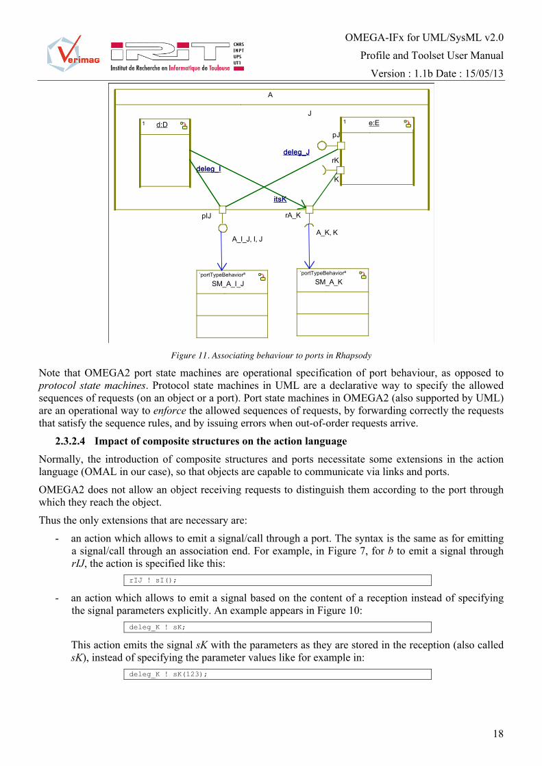
As Rhapsody v7.4 does not correctly export in XMI the state machines associated to interfaces, an alternative solution is provided for specifying port state machines. The behaviour is associated to a new class stereotyped <<portTypeBehavior>>, which is then linked to the port by a dependency, as shown in Figure 11.
EXT-3. OMEGA2 extensions:
3) Stereotype <<portTypeBehavior>> Applied on : Class Constraints: There has to be a Dependency connecting the concerned Port and the Class stereotyped <<portTypeBehavior>>.
OMEGA-IFx for UML/SysML v2.0
Profile and Toolset User Manual
Version : 1.1b Date : 15/05/13
18
A
d:D1 e:E1
K
rK
J
pJ
A_K, K
rA_K
itsK
A_I_J, I, J
pIJ
deleg_I
deleg_J
itsK
deleg_I
deleg_J
SM_A_I_J´portTypeBehaviorª
SM_A_K´portTypeBehaviorª
Figure 11. Associating behaviour to ports in Rhapsody
Note that OMEGA2 port state machines are operational specification of port behaviour, as opposed to protocol state machines. Protocol state machines in UML are a declarative way to specify the allowed sequences of requests (on an object or a port). Port state machines in OMEGA2 (also supported by UML) are an operational way to enforce the allowed sequences of requests, by forwarding correctly the requests that satisfy the sequence rules, and by issuing errors when out-of-order requests arrive.
2.3.2.4 Impact of composite structures on the action language Normally, the introduction of composite structures and ports necessitate some extensions in the action language (OMAL in our case), so that objects are capable to communicate via links and ports.
OMEGA2 does not allow an object receiving requests to distinguish them according to the port through which they reach the object.
Thus the only extensions that are necessary are:
- an action which allows to emit a signal/call through a port. The syntax is the same as for emitting a signal/call through an association end. For example, in Figure 7, for b to emit a signal through rIJ, the action is specified like this:
rIJ ! sI();
- an action which allows to emit a signal based on the content of a reception instead of specifying the signal parameters explicitly. An example appears in Figure 10:
deleg_K ! sK;
This action emits the signal sK with the parameters as they are stored in the reception (also called sK), instead of specifying the parameter values like for example in:
deleg_K ! sK(123);

OMEGA-IFx for UML/SysML v2.0
Profile and Toolset User Manual
Version : 1.1b Date : 15/05/13
19
2.3.2.4.1 Optional extensions
To achieve full power when using composite structures, the action language should also allow the dynamic creation of such structures. Object creation and direct assembly link creation is already supported by OMAL. An additional action type would be necessary in order to be able to initialize delegation links and assembly links involving ports.
This issue is not covered in the present project. 2.3.3 Behaviour
The behaviour description facilities of OMEGA2 are not changed with respect to the previous version. The behaviour is defined via state machines and primitive operations. Objects communicate by exchanging primitive operation calls, triggered operation calls and asynchronous signals (the two latter are handled by the state machine of the destination object).
OMEGA2 requires alignment with the UML 2.x standard for using these elements. This implies for example the definition of a Reception for every Signal used by a class, etc. Defining the well formedness rules for UML 2.x models is outside the scope of this document and we refer the reader to [1].
Note: The notions of primitive/triggered operation are natively supported by Rhapsody v7.4 (using the Rhapsody profile, which is applied by default to all models produced with the tool). For compatibility with other tools, we define the following extensions, which are optional in Rhapsody models:
EXT-4. OMEGA2 extensions:
4) Stereotype <<primitive>> Applied on : Operation
5) Stereotype <<triggered>> Applied on : Operation Constraints : Operation cannot have a body (action).
We are currently studying possible extensions to the OMEGA behavioural models (in particular extensions of state machines with concurrent states, etc.). These issues are left open in the current document.
2.3.4 Extensions and rules for the concurrency model The concurrency model is left open in UML. The previous version of OMEGA defined a particular concurrency model (see §2). The model is reused in OMEGA2 with some extensions and with additional constraints to maintain coherence with the use of composite structures (see §2.3.2).
2.3.4.1 Active and passive classes OMEGA2 makes the same distinction between passive and active classes as the previous version. An instance of an active class defines an activity group with its own thread of control. All passive objects created (directly or indirectly) by an active object belong to its activity group, and requests to all objects in the group (including the active one) are executed sequentially on the group’s thread of control in a run-to-completion fashion.
Note: The active/passive attribute of a class is a standard feature of the UML 2.x metamodel supported by Rhapsody v7.4. Visually, active classes and their instances are represented with thick border. In the previous version of the profile, passive classes could define a state machine. This unnecessarily complicates the semantics (in particular due to run-to-completion) and was not found to be useful in practice. We therefore impose the following:
WFR-9. OMEGA2 specific well-formedness constraints:

OMEGA-IFx for UML/SysML v2.0
Profile and Toolset User Manual
Version : 1.1b Date : 15/05/13
20
16. Only active classes may define a state machine.
17. The behavior of passive classes consists only of primitive operations.
Since the introduction of protected classes (next section) renders unnecessary the sharing of references to passive objects, passive objects in OMEGA2 are private to their activity group. This means that there can be no communication (signals/call) from outside an activity group directly to a passive object.
2.3.4.2 Protected classes In addition to this distinction, in order to overcome the problem of modelling shared objects in the previous version of OMEGA, a new kind of passive class can be defined in OMEGA2 using the stereotype <<protected>>. Protected objects are passive objects (i.e. they do not have their own thread of control) that do not belong to one activity group but rather are shared between the groups. They work in the same way as Ada protected objects [2].
Like in Ada, protected objects are a synchronization mechanism. They provide functions (which may only read but not modify object attributes) that can be executed concurrently, and entries that are executed in mutual exclusion from each other and from functions. This corresponds to the classical readers-writers pattern. An entry also has an associated guard; a call to an entry from a thread (activity group) will wait until the guard is true before beginning execution.$
Protected classes can be used to implement various synchronization patterns, like rendez-vous or semaphores.
EXT-5. OMEGA2 extensions:
6) Stereotype <<protected>> Applied on : Class Constraints : Class must be passive (isActive = false)
7) Stereotype <<function>> Applied on : Operation Constraints : Operation must be a primitive operation defined in a <<protected>> Class
8) Stereotype <<entry>> Applied on : Operation Tagged values : guard : String Constraints : Operation must be a primitive operation defined in a <<protected>> Class
The following figure shows the definition of a protected class.
X´protectedª
i:int
´functionª query():int´entryª modify(p:int):boolean
Figure 12. Definition of a protected class
2.3.4.3 Concurrency and composite structures In order to maintain coherence with the use of composite structures, some rules are imposed:
WFR-10. OMEGA2 specific well-formedness constraints: 18. A class that defines a composite structure (parts and/or ports) must be active.

OMEGA-IFx for UML/SysML v2.0
Profile and Toolset User Manual
Version : 1.1b Date : 15/05/13
21
19. The set of parts of a composite structure must either contain only passive elements, or a mixture of active/protected elements.
Rule 19 is introduced in order to avoid confusing configurations. For example, the composite structure in Figure 13 shows on a same level active objects b and c (which have their own activity group) and passive object d which belongs to the group of its creator (a). This kind of structure is forbidden.
A
b:B1 c:C1
d:D1
Figure 13. Forbidden composite structure
A composite structure can instead define a mixture of active and protected objects, as protected objects are not owned but shared between activity groups. Figure 14 is therefore legal.
A
b:B1 c:C1
d:D1 ´protectedª
Figure 14. Sound composite structure formed of active/protected objects
2.3.5 Extensions and rules for object and system initialization Composite structures offer an alternative (sometimes more convenient) to constructors for defining the initialization of a structure of objects. The constructor notion is also preserved in OMEGA2.
EXT-6. OMEGA2 extensions:
9) Stereotype <<constructor>> Applied on: Operation Constraints: Operation must be a primitive operation
Note : Rhapsody v7.4 offers a construct called Initializer, which is a sub-type of primitive operation. OMEGA2 models can use either “normal” primitive operations or initializers as constructors. The <<constructor>> stereotype is optional for initializers, and is defined only for compatibility with other UML 2.x tools. System initialization is defined by marking one of the active classes as the root system class. An object of this class (together with its internal composite structure) is created by default at system initialization.

OMEGA-IFx for UML/SysML v2.0
Profile and Toolset User Manual
Version : 1.1b Date : 15/05/13
22
EXT-7. OMEGA2 extensions:
10) Stereotype <<root>> Applied on: Class Constraints: the Class must be active
Systems in OMEGA2 are closed, i.e., they must contain a model of the environment, and therefore have no open connections. We therefore also impose the following:
WFR-11. OMEGA2 specific well-formedness constraints:
20. The system root Class cannot declare any ports.
2.3.6 Extensions and rules for observers Observers are defined in the same way as in OMEGA UML 1.4.
An observer is specified in the UML model by a class stereotyped with <<Observer>>. The automaton defining the observer property is the UML state machine of that class.
EXT-8. OMEGA2 extensions:
11) Stereotype <<observer>> Applied on: Class Constraints: The Class must be active. The class cannot declare any Ports.
An observer can define a simple composite structure according to the rules in section 2.3.2.1. In this case, the sub-components have also to be observers. The following rules apply:
WFR-12. OMEGA2 specific well-formedness constraints: 21. If a Class stereotyped <<observer>> defines a composite structure, the components must also
be instances of classes stereotyped <<observer>>.
22. Globally within a model there cannot be more than one instance of a Class stereotyped <<observer>>.
The state machine of an <<observer>> class may react either to Boolean conditions (based on variables in the model), or to events. The event types to which an observer may react are a subset of the ones defined in the OMAL grammar (see [4]) by the <EventMatchingStatement> non-terminal. More specifically, OMEGA2 supports the following event types: informal events and interaction events.
Note: as these event types are not supported by Rhapsody v7.4, the event specification is included in the action part of transitions, separated by a “//” from the actual transition effect (action). In order to obtain a property specification, the user has to classify some states of the observer as error states.
EXT-9. OMEGA2 extensions:
12) Stereotype <<error>> Applied on: State Constraints: none.
2.3.7 OMEGA action language syntax changes The OMEGA action language defined in [4] remains unchanged, with the exception of one minor syntactic change is induced by the changes in how Signals are declared and used in UML 2.x. In OMEGA for UML 1.x a signal input had a particular syntax, which specified the signal name, and a list of variables in which the actual signal parameters were stored when the input was triggered, like in Figure 15 (here,

OMEGA-IFx for UML/SysML v2.0
Profile and Toolset User Manual
Version : 1.1b Date : 15/05/13
23
x,y, and z are attributes of the class owning this state machine). As this syntax was not supported by Rhapsody, it had to be fitted in the action part of a transition.
state_0
/Signal1(x, y) // z := x + y
state_1
/Signal1(x, y) // z := x + y
Figure 15. OMEGA UML 1.x syntax for Signal input (deprecated)
In UML 2.x, for every Signal handled by a class, the class has to define a Reception. The reception can therefore be used as a reference to the actual instance of the Signal that is received. Based on this reference, signal parameters can then be accessed as any object attribute. The reception can be used as a trigger using the standard Rhapsody syntax. Here is an example (arg1 and arg2 are the names of the formal parameters defined in Signal1) :
state_0
Signal1/z := Signal1.arg1 + Signal1.arg2
state_1
Signal1/z := Signal1.arg1 + Signal1.arg2
Figure 16. OMEGA2 syntax for Signal input
This syntax necessitates a rule that is not enforced by Rhapsody:
WFR-13. OMEGA2 specific well-formedness constraints: 23. A Reception cannot have the same name as an Attribute of a Class.

OMEGA-IFx for UML/SysML v2.0
Profile and Toolset User Manual
Version : 1.1b Date : 15/05/13
24
3 The software package
3.1 What do you need in order to run IFx-OMEGA
o A binary version of IFx for a supported platform. Binary distributions of IFx can be obtained at http://www-if.imag.fr/download.php . A distribution is an archive named according to the following syntax: IFx-2.0.(platform_name).(build_date).tgz See section 3.3 for the platforms codes.
o A binary distribution of IFx-OMEGA, which is composed of 2 JAR files (ifsimgui.jar and uml2if.jar). The IFx-OMEGA JAR files have to be installed in a working copy of IFx, under $IF/bin. Binary distributions of IFx can be obtained at http://irit.fr/ifx/download.html .
3.2 Other available components
Other components are included in the IFx-OMEGA distribution or available on the website (http://irit.fr/ifx/download.html) :
o The Rhapsody packages for OMEGA2 profile and the OMEGA2Predefined library (OMEGA2.sbs and OMEGA2Predefined.sbs), to be included in all UML/SysML models.
o 2 example models:
ATM : A model of a simple Automated Teller Machine (and its environment). The model is used as a running example in Section 4.
ATM with error in property : The same model as ATM, but with a bug. This allows to see how the verifier finds the bug, to simulate the error scenario, etc.
o A set of binary libraries (C++ and Java) on which IFx2 depends. These files are provided for convenience only. They are the property of their respective owners and may be used subject to the respective license agreement.
o Eclipse EMF/UML2: The files can be obtained from the Eclipse project website (www.eclipse.org), or, alternatively, from the IFx site (www.irit.fr/ifx). Files that are needed (be sure to get the exact versions listed here) :
org.eclipse.emf.common_2.6.0.v20100914-1218.jar
org.eclipse.uml2.common_1.5.0.v201005031530.jar
org.eclipse.emf.ecore.xmi_2.5.0.v20100521-1846.jar
org.eclipse.uml2.uml.resources_3.1.1.v201008191505.jar
org.eclipse.emf.ecore_2.6.1.v20100914-1218.jar
org.eclipse.uml2.uml_3.1.1.v201008191505.jar
org.eclipse.uml2.common.edit_1.5.0.v201005031530.jar
org.eclipse.uml2_3.0.0.v201005031530.jar
The Eclipse Public Licence applies, see http://www.eclipse.org/org/documents/epl-v10.php.
o Xerces-C 3.1. The Apache License applies, see http://www.apache.org/licenses

OMEGA-IFx for UML/SysML v2.0
Profile and Toolset User Manual
Version : 1.1b Date : 15/05/13
25
3.3 Platform requirements
This software runs on the following platforms with the respective version of GCC2:
o x86_64: Linux 64bit on Intel x86_64 / GCC 4.4.7 (or compatible)
o Mac_iX86: Mac OS X 10.6 (or compatible) 64bit on Intel x86_64 / GCC 4.2.1 (or compatible)
In addition, the toolset requires the following components to function correctly:
o Java version 1.6.0_04 (or compatible)
o Xerces-C 3.1 (see section 3.2)
o Eclipse EMF and UML libraries (see section 3.2)
3.4 IFx Installation instructions
This section reviews the installation procedure for UNIX-like environments (Linux, Mac OS X). Differences exist for Windows/Cygwin, see INSTALL file included in IFx-2.0.*.*.tgz.
In order to install IFx2 toolkit you need to follow these instructions:
• Create a new directory (for example /usr/local/if2 )
• Extract the archive IFx-2.0.*.*.tgz in the new directory
• Set the $IF environment variable to refer the directory where IF software is installed. The syntax is depending on the shell your are using, for example:
o bash : export IF=/usr/local/if2
o csh/tcsh : setenv IF /usr/local/if2
• Check that the architecture is correctly detected by executing $IF/com/arch This should display the same architecture string that appears in the name of the tarball (here, x86_64)
• Add into your $PATH variable the $IF/com and $IF/bin/`arch` directories. o bash : export PATH=$IF/com:$PATH
export PATH=$IF/bin/`arch`:$PATH
o csh : setenv PATH $IF/com:$PATH setenv PATH $IF/bin/`arch`:$PATH
• Some execution rights might not be correctly preserved when opening the tarball. Correct them using:
chmod 755 $IF/com/*
• If you are behind a proxy server for Internet access (used by uml2if for validating XMI schemas) than the following variables must be set:
o export proxyHost=<DNS name or IP address of your proxy server>
o export proxyPort=<proxy server port number>
2 The version provided here correspond to our validation environments. Other versions may function correctly.
OMEGA-IFx for UML/SysML v2.0
Profile and Toolset User Manual
Version : 1.1b Date : 15/05/13
26
• If you are behind a proxy server for Internet access (used by uml2if for validating XMI schemas) than the following variables must be set:
• Installation of Apache Xerces-C XML parser
o Download the parser from http://xml.apache.org/
o Set the variable XERCESLIB to point at the directory containing the xerces-c parser libraries (libxerces-c.so or xerces-c_2.lib)
bash : export XERCESLIB=<dir>
csh : setenv XERCESLIB <dir>
o On UNIX/Linux/MaxOS; add $XERCESLIB to the $LD_LIBRARY_PATH bash : export LD_LIBRARY_PATH=${XERCESLIB}:${LD_LIBRARY_PATH}
csh : setenv LD_LIBRARY_PATH ${XERCESLIB}:${LD_LIBRARY_PATH}
3.5 IFx-OMEGA Installation instructions
The binary distribution of IFx-OMEGA is composed of 2 JAR files (ifsimgui.jar and uml2if.jar). Simply copy the JAR files in a working copy of IFx, under $IF/bin.
All Eclipse EMF-UML JAR dependencies listed in section 3.2 have to be copied also under $IF/bin.

OMEGA-IFx for UML/SysML v2.0
Profile and Toolset User Manual
Version : 1.1b Date : 15/05/13
27
4 OMEGA2 modeling tutorial (with IBM Rhapsody)
In this section we present the modeling of a simple system, an automated teller machine (ATM) with OMEGA2.
4.1 ATM problem statement
The system to be designed will control a simulated automated teller machine (ATM) having a magnetic stripe reader for reading an ATM card, a customer console (keyboard and display) for interaction with the customer and a dispenser for cash. The ATM will communicate with the bank's computer over an appropriate communication link.
The ATM will service one customer at a time. A customer will be required to insert an ATM card and enter a personal identification number (PIN). The customer will then be able to perform one or more transactions. The card will be retained in the machine until the transaction is completed.
The ATM must be able to provide the following services to the customer:
1. A customer must be able to make a cash withdrawal from any suitable account linked to the card. Approval must be obtained from the bank before cash is dispensed.
2. A customer must be able to make a transfer of money between any two accounts linked to the card.
3. A customer must be able to make a balance inquiry of any account linked to the card.
The ATM will communicate each transaction to the bank and obtain verification that it was allowed by the bank. Ordinarily, a transaction will be considered complete by the bank once it has been approved or disapproved.
If the card unit determines that the customer's PIN is invalid, the customer will be required to re-enter the PIN before a transaction can proceed. If a transaction fails for any reason other than an invalid PIN, the ATM will display an explanation of the problem and end the transaction.
4.2 Basic modeling in OMEGA2
Note: To create OMEGA2 UML models we use Rhapsody Developer v7.4. OMEGA2 models use a profile and a predefined library provided with the tool (OMEGA2.sbs and OMEGA2Predefined.sbs). To use them in Rhapsody, select "File/Add to model…" and open files OMEGA2.sbs and OMEGA2Predefined.sbs. From the problem statement, we can deduce the existence of two composite structures: System which contains as objects a user, a bank and the atm we want to model, and ATM which contains as objects a controller, a reader, a console and a dispenser. Each of these two classes must be added using the Composite class (or Block for SysML models) button from Rhapsody palette.
For each of the components mentioned before, we need to add the corresponding classes (blocks). We have identified the following ones: User, Bank, Controller, CardReader, CashDispenser and Console.
Finally, from the problem statement we identify that all classes defined previously (simple or composite) are active. To define a class (block) as active we need to set the corresponding attribute Concurrency in Features, as in Figure 17.

OMEGA-IFx for UML/SysML v2.0
Profile and Toolset User Manual
Version : 1.1b Date : 15/05/13
28
Figure 17. Active class definition
The class System must be stereotyped with root, since it is the class defining the overall system structure. To use this stereotype in Features, we have to select root from the Stereotype combo-box:
Figure 18. “Root” stereotype

OMEGA-IFx for UML/SysML v2.0
Profile and Toolset User Manual
Version : 1.1b Date : 15/05/13
29
4.3 Communication modeling
Figure 19. Ports and links model
The overall structure of the system is given in Figure 19. Keep in mind that in OMEGA2 ports are unidirectional, meaning that we can only send messages through the port or receive messages through the port. If a component can send and receive messages we have to model this with at least two ports.
Every port has to define a contract. A contract is an interface containing operations’ definition (without the body) and signals’ reception for which the class and/or the port knows how to react. If we have two or more interfaces defining the needed requests, we need to define a new interface that inherits from the others. This interface has to be stereotyped with portType.
Figure 20. “portType” stereotype
A Port’s usual behavior is to forward messages according to its direction. A required port may be modeled either using the stereotype reversed or, in Rhapsody, using the reversed checkbox in the port

OMEGA-IFx for UML/SysML v2.0
Profile and Toolset User Manual
Version : 1.1b Date : 15/05/13
30
properties as shown in Figure 21 (which adds a Rhapsody stereotype equivalent to reversed). If the port is owned by a class and has to forward the messages to the class, the port must be set declares as behavior port, like in Figure 22.
Figure 21. Reversed port example
Figure 22. Behavior port example

OMEGA-IFx for UML/SysML v2.0
Profile and Toolset User Manual
Version : 1.1b Date : 15/05/13
31
Ports are connected with other ports and/or classes by connectors. More information about rules for connectors can be found in Section 2.
4.4 Behavior modeling
In OMEGA2, state machines can be defined for classes and ports. To define a state machine for a class, in the Model View right click on the class, select Add new and from the new pop-up menu select Statechart. For a port, a new Interface must be defined. The port must be connected to the interface with a Dependency connection. This interface should be stereotyped with <<portTypeBehavior>> and it contains the state machine for the port.
The syntax of actions on state machines should conform with the OMEGA Action Language (OMAL [4]). OMEGA2 offers a simpler use of signals. If a reception is defined for a signal with parameters, than these can be accessed directly through the reception. An example is shown in the Figure 23.
Figure 23. Signal parameters accessed through reception
A complete statemachine is presented for Console class that forwards signals received from the ATM Controller to the User and vice-versa.

OMEGA-IFx for UML/SysML v2.0
Profile and Toolset User Manual
Version : 1.1b Date : 15/05/13
32
Figure 24. Console’s statechart
4.5 Property modeling
For specifying and verifying dynamic properties of UML models, OMEGA uses the notion of UML observers. Observers are special objects monitoring run-time state and events. Observers are defined by classes stereotyped with <<observer>>. They may have local memory (attributes) and a state machine describes their behavior. Sates are classified as <<error>> states to express properties and hypotheses.
The trigger of an observer transition is a match clause specifying the type of event (e.g., receive), some related information (e.g., the operation name) and observer variables that may receive related information (e.g., variables receiving the values of operation call parameters). Besides events, an observer may access any part of the state of the UML model: object attributes and state, signal queues. In order to express quantitative timing properties, observers may use the concepts available in the OMEGA profile such as clocks.
The observer in Figure 25 specifies the following property about the ATM : If a withdrawal succeeds, the delivered amount is always equal to the requested amount.

OMEGA-IFx for UML/SysML v2.0
Profile and Toolset User Manual
Version : 1.1b Date : 15/05/13
33
Figure 25. A property of ATM formalized by an observer

OMEGA-IFx for UML/SysML v2.0
Profile and Toolset User Manual
Version : 1.1b Date : 15/05/13
34
5 How to use the IFx2 toolset
5.1 Overall architecture
OMEGA2 models can be simulated and properties can be verified using the IFx2 toolset. We use the following terminology:
- Verification designates the automatic process of verifying whether an OMEGA2 UML/SysML model satisfies (some of) the properties (observers) defined on it. The verification method employed in IFx is based on systematic exploration of the system state space (a.k.a., enumerative model checking).
- Simulation designates the interactive execution of an OMEGA2 UML/SysML model. The execution can be performed step-by-step, random, or guided by a simulation scenario (for example an error scenario generated during a verification activity).
The IFx toolset relies on a translation of UML/SysML models towards a simple specification language based on an asynchronous composition of extended timed automata (IF), and on the use of simulation and verification tools available for IF. The translation takes in input models in XMI 2.0 format; it has been designed to work in conjunction with IBM Rhapsody (version 7.4 or later) but functions correctly with other XMI-compliant tools.
The architecture of the tool is shown in Figure 26. The OMEGA2-specific tools are depicted in the upper half of the figure, while the lower part shows the various components of the IF layer.
Figure 26. IFx toolset architecture
5.2 Overall workflow
The overall workflow with the OMEGA2 profile and IFx2 is shown in Figure 27.

OMEGA-IFx for UML/SysML v2.0
Profile and Toolset User Manual
Version : 1.1b Date : 15/05/13
35
Figure 27. IFx2 workflow
The activities shown in this workflow are detailed in the following.
5.3 Export OMEGA2 model as XMI 2.0
This step depends on the UML editor that is used. For IBM Rhapsody version 7.4:
1. Select menu “Tools/Export XMI from Rhapsody”
2. In the dialog, make sure to select Format “UML 2.2” and XMI Version “XMI 2.1” (see Figure 28)
3. In menu “Window/Options”, make sure every model element type is selected (see Figure 29)
4. “Select” button explores file system tree until one output is selected.
5. Finally, “Proceed” button must be pressed to generate the XMI file.

OMEGA-IFx for UML/SysML v2.0
Profile and Toolset User Manual
Version : 1.1b Date : 15/05/13
36
Figure 28. Rhapsody XMI export
Figure 29. XMI export options
5.4 uml2if : compiling the OMEGA2 model
uml2if is a command line tool located in directory $IF/com.
Syntax: uml2if [options] OMEGA2-model-filename.xml
where options are:
o -rhapsody : informs compiler that the XMI file was generated by Rhapsody
o -o <filename.if> : output file name
o -nqn : generate unqualified names for UML entities. By default, every UML entity is compiled to an IF process whose name is prefixed with the names of all namespaces from the root (model package) to the entity.
o -val : deprecated
o -nc : deprecated

OMEGA-IFx for UML/SysML v2.0
Profile and Toolset User Manual
Version : 1.1b Date : 15/05/13
37
o -now : force generation of 'now' clock in IF code
o -eager : eager time model. Specifies that the semantics of the model is such that any transition is fired as soon as it is enabled, without idle waiting. It is suggested to use this option at first for model verification, as it generates much smaller state spaces. However, positive verification results (i.e., no error found) should be carefully considered since this semantics yields only a subset of all possible executions of a system.
o -insist : continue as much as possible upon errors
o -ignore <element> : ignore model element and items contained therein. Element is a qualified name in the UML model namespace hierarchy.
o -ignf <filename> : ignore model elements listed one per line in file <filename>
Output: The output of uml2if is either a list of error messages or, if there is no error, an IF file containing the translation.
N.B.: There are errors which are not detected by uml2if and can be detected later by the IF compiler (for example, UML entity names which are IF keywords).
5.5 dfa : automatic abstractions
dfa is a command line tool located in directory $IF/bin/<architecture>.
The most common usage of dfa is to add dead variable reductions to the model. This is a conservative abstraction which can be used fully automatically on any model without loss of precision.
Syntax: dfa –live model1.if > model2.if
Output: The command creates an IF model (model2.if) which is semantically identical to model1.if (i.e., it
allows the same execution sequences) but which has a smaller state space and so is more efficient for verification.
5.6 if2gen : compiling the IF model
if2gen is a command line tool located in directory $IF/com
Syntax: if2gen [-tdiscrete | -tdbm] model.if
Options: o -tdiscrete signifies that a discrete time model is used for timers (i.e., timers have integer values at
any moment, and time progresses in ticks).
o -tdbm signifies that a continuous time model if used for timers (i.e. timers have real values and state exploration is done symbolically using timer inequations).

OMEGA-IFx for UML/SysML v2.0
Profile and Toolset User Manual
Version : 1.1b Date : 15/05/13
38
Discrete time is a non-conservative abstraction. However, it is recommended in a first time for verification, as it yields smaller state spaces.
Output: The output of if2gen is either a list of error messages or, if there is no error, an executable file containing the IF model and the simulation/verification functions.
The name of the executable is model.exe for Windows architectures, and model.x for other architectures.
5.7 Automatic verification (model.exe)
The executables generated by if2gen are used to perform both automatic verification and interactive simulation. For automatic verification, the main options concern:
The exploration order. The state space of a model can be seen as a large graph. It can be explored either in breadth-first (-bfs) or in depth-first (-dfs) order.
Error handling. If errors are found, the user can ask that error scenarios are generated using the –me option. Option –ce allows to stop exploration of successors of any error states.
N.B. error scenarios can only be generated if the search order is DFS. Every scenario is generated in a separate file named e<number>.scn. Partial order reduction. This is a conservative form of abstraction that can be applied on any model during state space search to yield smaller state spaces. The option –po is used in order to activate it.
5.8 if2gui: interactive simulation
if2gui is a graphical user interface that can be launched from command line (the if2gui command is located under $IF/com).
Syntax: if2gui [model.exe]
5.8.1 Running principle if2gui relies on the generated model executable (see if2gen) in order to simulate the model, cf. Figure 30.
Figure 30. if2gui runtime architecture
The model executable can be launched separately (e.g. on a different machine) and the if2gui can connect to it (menu “Simulate/Attach to IF simulator”). Alternatively, if2gen can launch the model executable, either from the menus (menu “Simulate/Run IF simulator”) or at startup if the name of the model executable is specified as a parameter to the if2gui command (cf. Syntax above).
5.8.2 Main components of the interface The main components of the GUI are identified in Figure 31.

OMEGA-IFx for UML/SysML v2.0
Profile and Toolset User Manual
Version : 1.1b Date : 15/05/13
39
Figure 31. if2gui interface
5.8.3 Simulation actions The following actions are available (either from the menu or from the toolbar):
- bring the system to the initial state (again)
- trigger the selected transition. This can also be done by double-clicking on a transition in the enabled transitions view.
- Load a scenario from a file. That may be a scenario generated from verification. N.B. in this case, the system must be in the initial state when the scenario is loaded.
- Save the current scenario (sequence of executed transitions) in a file for later replay.
- Step forward/backwards in the current scenario (if such a step is available)
- Go to beginning/end of current scenario
- Go to a step specified by a number
5.8.4 Structured views Every tree view in the interface (system state view in the left pane, enabled transitions in the right pane) is the representation of an XML document. The elements are represented in black; the attributes are represented in blue.

OMEGA-IFx for UML/SysML v2.0
Profile and Toolset User Manual
Version : 1.1b Date : 15/05/13
40
5.8.5 Stop conditions Below every tree view, there is a panel called “Stop conditions”, where the user may write an Xpath query to be executed over the XML document represented in the view. This query is executed every time the simulator reaches a new state (in interactive or random simulation), and a message is displayed when the query evaluates to true (or to an Xpath value assimilated to true, such as a non-empty node set, etc.) In random mode, reaching a true condition stops the simulation.
In order to help the user write the stop conditions, a panel called “Selection” displays the Xpath expression for reaching node that is he currently selected in the XML view (content changes each time the selection changes in the XML view). This expression may be copied in the “stop conditions” panel and modified in order to obtain the desired condition.
The expression provided by the “Selection” panel is approximate, in the sense that is assumes that every element is distinguishable in its context by the (unique) combination of values of its attributes. Therefore, the selection is based on the values of the attributes of every node on the path from the root to the selected node. Note that for general XML documents, this assumption may be false, and there may be cases where two different nodes are not distinguishable at all by the means of Xpath.
Examples
Here are several examples of stop conditions, for usual cases:
- stop when variable b of the first instance of process type receiver has the value true.
In view “Configuration”, the stop condition would be:
/instances/receiver[self/pid/@name=”receiver” and self/pid/@no=”0”]/b/boolean/@value = “true”
or an equivalent form (maybe slower to evaluate)
/*/*[ self/pid/@name=”receiver” and self/pid/@no=”0”]/b/*/@value = “true”
- stop when variable b of the first instance of UML class receiver has the value true.
In view “UML objects”, the stop condition would be:
/objects/receiver[@no=0]/b/boolean/@value = “true”
- stop when the signal s is about to be output
In view “Transitions”, the stop condition would be:
starts-with( /*/*/*[@kind="OUTPUT"]/@value, "s{")
5.8.6 Other functions Information provided in the transitions view may be too detailed for certain uses, and the user may want not to see some event types. This may be obtained using the menu “View/Filter events”.
Custom views may also be added by the user (see menu “View/Add state view”). Note however that this requires a good knowledge of the XML structure used by the IF simulator, and XSLT programming skills.
5.9 Using the examples
The steps detailed above can be applied to all the examples provided with the software package.
The example in directory “ATM with error in property” allows exercising the verifier and finding error scenarios. For that, follow these steps:

OMEGA-IFx for UML/SysML v2.0
Profile and Toolset User Manual
Version : 1.1b Date : 15/05/13
41
1. compile the ATMb.xmi file using the –eager option: $ uml2if –rhapsody –eager ATMb.xmi
2. compile the generated IF file using: $ if2gen ATMb.if
3. run the verifier using: $ ATMb.x ATMb.x -dfs -po -me -ce –ln 11 error scenarios are found (ls *.scn).
The errors found in this step correspond to an error in the specification of the property (Figure 25). Indeed, after a withdrawal request made by the user (signal amount), the ATM may decline the request. Thus, the subsequent signal releaseMoney, observed in state state_1 may correspond to a different amount requested afterwards, which leads the observer to the error state. A corrected version of the observer is given in the example model ATM.rpy from the OMEGA-IFx distribution.
4. run the simulator: $ if2gui ATMb.x then load and run one of the error scenarios from the GUI.

OMEGA-IFx for UML/SysML v2.0
Profile and Toolset User Manual
Version : 1.1b Date : 15/05/13
42
6 Frequent problems and solutions
6.1 Modeling
1. I get a lot of “unknown data type” errors, but I don’t use any user-defined data types. There are three basic data types supported by OMEGA2: integer, real and boolean. They are defined in the OMEGA2Predefined.sbs package. However, the Rhapsody editor has a bug which makes it impossible to import basic types between packages, so the basic types cannot be used as such.
Instead, you should redefine integer, real and boolean in all the packages contained in your model. For example, when defining an operation parameter, write the name of the type in all letters in the space provided for this purpose: the type will be automatically created (in the current package) if it does not already exist. See also the examples provided in the software package.
6.2 Simulation:
2. GUI error: “Exception raised when executing simulator: Connection refused” This error appears occasionally when running “if2gui model.exe” with a newly created model.exe simulator executable. If this is the case, simply running the same command again would not give the same error.
In other conditions, for example if the simulator executable has been launched manually, this signifies that the host/port provided manually in the GUI is incorrect.
3. GUI error: “Protocol error” This error may appear in the GUI when the simulator executable terminates unexpectedly.
A possible cause for the simulator executable to terminate unexpectedly is when the IF code executes a faulty instruction, e.g. use an invalid instance address (equivalent to a null-pointer error in a programming language). In this case, running the model executable in verification mode (e.g. “model.exe –dfs”) will normally allow to find the source of the problem (the invalid instance address that is causing the crash).
6.3 Verification:
4. Model verification does not terminate. This is a common situation. The state space of a system may be very large for good reasons (the system is complex by nature, contains a lot of dependent parallel activities). However, the state space is sometimes very large for wrong reasons, such as: a counter variable increasing continuously, a timer variable that is not reset and continues to grow, messages accumulating in the queue of one process (the executions are unfair wrt. that process).
There are several steps that need to be taken in this case:
a) Identify the problem: when the state space is infinite because of a variable or a queue growing infinitely, this can in general be seen by in DFS verification mode.
Example of output in DFS verification: marvin[512]:~/XPSF/tests/uml22if$ ./ATM2.x -dfs

OMEGA-IFx for UML/SysML v2.0
Profile and Toolset User Manual
Version : 1.1b Date : 15/05/13
43
00:00:07 38825/s 38982/t 38824/d
The numbers printed by the verifier (every second) represent respectively the total number of states and transitions (since the beginning of the exploration) and the current DFS depth. When the depth grows at the same rate as the state number, this means that (almost) every explored state is different from the previous ones, which in general is caused by a growing variable, timer or queue.
b) Identify the source of the problem: There is no tool for automatically identifying which variable/timer/queue is causing the problem. One way to find the cause is to store the state space in a file (see option –q in verifier) and look for unusually large values or long message queues.
c) Correct the problem: Again, there is no easy or unique solution for correcting the problem. Some heuristics:
o First, make sure that the problem is not caused by an unused variable. Always use the live variable reduction (dfa –live) before simulation or verification.
o If you have counters in your model, count modulo n (using the smallest value for n which makes sense).
o If the source is a timer growing indefinitely, you may want to use a stricter timing model for your system, for example by using the uml2if –eager option, or alternatively using a symbolic time (if2gen –tdbm).
o If the source is a message queue growing indefinitely, it generally points to a logical fault in the model: for example there is no feedback loop in a producer-consumer pair, and the producer is faster than the consumer. In this case, you may want to use acknowledgements or another flow regulation protocol for the link in question.