Olympus BX60 - NRI-MCDB Microscopy Facility | UC …€“NUA – DAPI and other blue appearing...
28
Olympus BX60 Introduction to the NRI-MCDB Microscopy Facility BX60 Upright Microscope
Transcript of Olympus BX60 - NRI-MCDB Microscopy Facility | UC …€“NUA – DAPI and other blue appearing...
Olympus BX60
Introduction to the
NRI-MCDB Microscopy Facility
BX60 Upright Microscope
Contents
• Start-up
• Preparing for Imaging
– Part I – General
– Part II – Transmitted
– Part III – Fluorescence
• Shut-down

Step 1: Sign-in
• Record the following: – Date: – Your name: – Your Project Code (i.e. Index
Code): – Your Principal Investigator (PI): – Extension (Optional): – Hg On (hour listed on the
Mercury Burner): – Hg Off – (fill-in when you
finish): – Time-in (the time you arrived): – Time-off (the time you left): – Comments (any notes on
system condition)
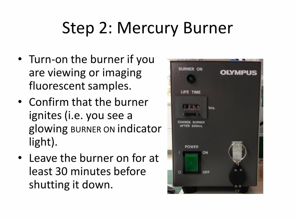
Step 2: Mercury Burner
• Turn-on the burner if you are viewing or imaging fluorescent samples.
• Confirm that the burner ignites (i.e. you see a glowing BURNER ON indicator light).
• Leave the burner on for at least 30 minutes before shutting it down.

Step 3: Turn on the Microscope
Turn on the microscope using the switch in the back. This supplies power to the tungsten-halogen light used for transmitted light imaging. You need only turn it on if you will be doing transmitted imaging (e.g. Brightfield, DIC)

Step 4: Turn Camera Power Supply
• Switch-on the power supply to the camera if you plan to image your samples.
• The power supply is located between the BX60 and the computer monitor.

Step 5: Turn-on/Set-up the computer
• Turn-on the computer, located under the counter to the far right of the microscope.
• Log-in using your ADS account name and password.
• From the start menu, select Run and then type – \\microscopy-nas1.nri.ucsb.edu – Create a shortcut for future use.

Preparing for Viewing and Imaging
• Part I General Preparation
• Part II – Transmitted Light Applications
• Part III – Fluorescence Applications Critical for Transmitted
Light Applications Critical for Transmitted
Fluorescence Applications

General Prep - Adjust the Eyepieces
• Adjust the spacing to accommodate your interpupillary distance.
• For those with vision corrected to normal, position the diopter to 0. To correct the system for your eyes adjust the diopter.

General Prep – Set the beamsplitter
• For viewing with the eyepieces position the slider all the way in.
• For transmitted light imaging the middle or all to the camera position will work.
• For imaging fluorescence pull the slider all the way out to direct all the light to the camera.

Part II: Preparing the microscope for transmitted imaging
• Direct light to the transmitted path.
• Adjust the light intensity. • For transmitted color
imaging use the neutral density filters to adjust the light intensity. At low magnification add all the ND filters and remove them as you increase magnification (because you need more light at higher magnification).
Transmitted
Reflected Path (Not available)
Light Intensity
Daylight blue filter makes light bluer
Neutral Density Filters change the light intensity without changing color tone of the light

Part II: Confirm that no extra optical components are in place
• Remove any fluorescent filter cubes from the light path
• Remove all polarizing filters and DIC components
NUA is the DAPI cube
Rotate to WU (no cube)
Polarizing filter out
Condenser is set for BF (Brightfield)
empty

Part II: Establish Kohler Illumination
Do not rotate by grabbing the objectives
Rotate using the nosepiece
• Place a slide on the stage
• Rotate the 10x objective into position using the nosepiece.
Part II: Establish Köhler Illumination continued
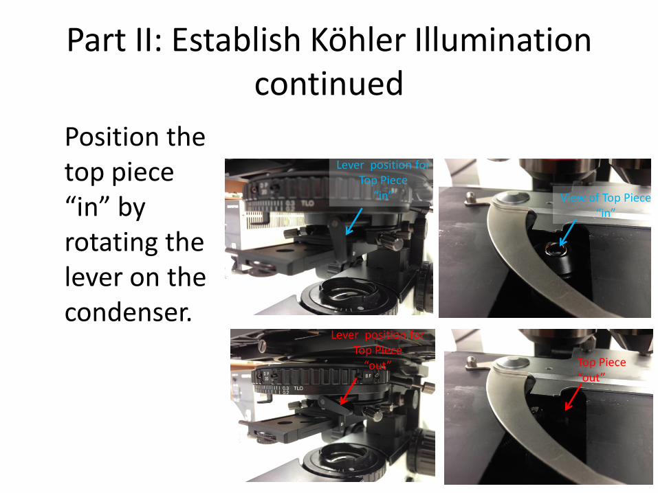
Position the top piece “in” by rotating the lever on the condenser.
View of Top Piece “in”
Top Piece “out”
Lever position for Top Piece
“in”
Lever position for Top Piece
“out”
Part II: Establish Köhler Illumination continued
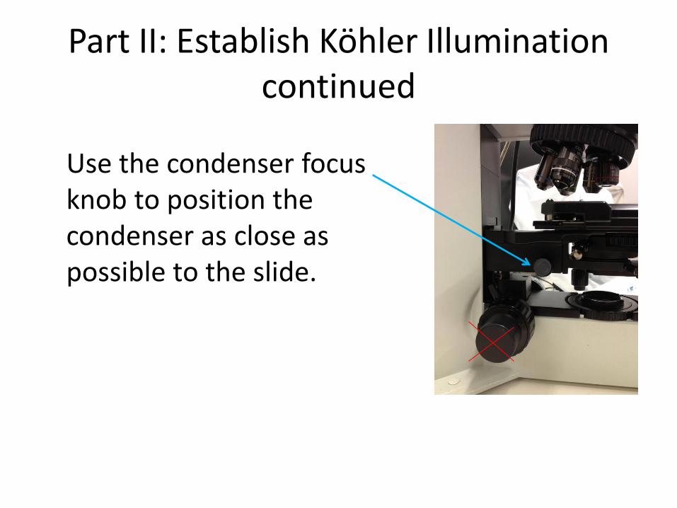
Use the condenser focus knob to position the condenser as close as possible to the slide.

Part II: Establish Köhler Illumination continued
Use the microscope focus knob to bring the sample into crisp focus.
Part II: Establish Köhler Illumination continued
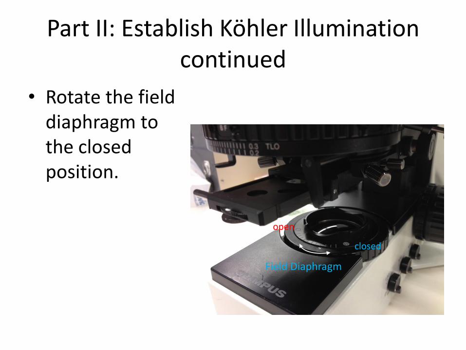
• Rotate the field diaphragm to the closed position.
Field Diaphragm
closed
open

Part II: Establish Köhler Illumination continued
Use the condenser focus knob to adjust the condenser height so that the field diaphragm appears crisply focused when viewed through the microscope.

Part II: Establish Köhler Illumination continued
• Use the centering knobs located on the left and right sides of the condenser to center the view of the field diaphragm.
Centering Knob
Centering Knob
Part II: Establish Köhler Illumination continued
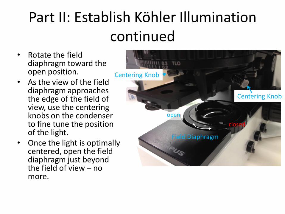
• Rotate the field diaphragm toward the open position.
• As the view of the field diaphragm approaches the edge of the field of view, use the centering knobs on the condenser to fine tune the position of the light.
• Once the light is optimally centered, open the field diaphragm just beyond the field of view – no more.
Field Diaphragm
open
closed
Centering Knob
Centering Knob

Part II: Establish Köhler Illumination continued
• Adjust the condenser diaphragm to optimize contrast – ¾ of the entire light disc
visible in the eye tube after removal of the eyepiece for stained specimens
– ½ or less for transparent specimens
– Or to taste but the more closed the diaphragm the lower the NA of the system

Part II: Reestablish Köhler Illumination
• Kohler illumination is objective specific
• Reestablish Kohler Illumination for each objective

Part III: Preparing the microscope for fluorescence imaging
• Direct transmitted illumination to the reflected path if you are alternating between transmitted and fluorescence imaging.
• Otherwise, turn-off or leave off the transmitted light using the microscope power switch on the back of the microscope.
Transmitted
Reflected Path (Not available)
Light Intensity

Part III: Filter Turret
• Position the desired filter cube in the light path. – NUA – DAPI and other blue
appearing probes excited by near UV.
– WB – FITC, Cy2, Alexa488 and other green appearing probes excited by blue light.
– WG for TRITC, Cy3 and other red appearing probes excited by green light
NUA is the DAPI cube
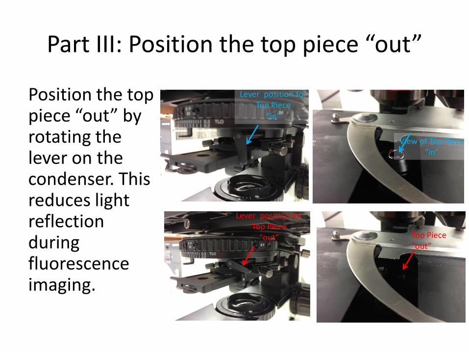
Part III: Position the top piece “out”
Position the top piece “out” by rotating the lever on the condenser. This reduces light reflection during fluorescence imaging.
View of Top Piece “in”
Top Piece “out”
Lever position for Top Piece
“in”
Lever position for Top Piece
“out”

Part III: Open the Shutter
• Push the Shutter Slider in to open the light path.
• Close the shutter whenever you are not viewing or imaging by pulling on the Shutter Slider.
• The Sliders marked FS and AS should always be open (in).

Shut-Down Procedure
• Check the online schedule – Shut-down if nobody is scheduled within the next
hour – Leave the system on if somebody is using the system
in the next hour but do the following. • Log-off the computer • Close the fluorescent shutter • Clean-up • Return to the 10x objective • Sign-off in the log.
• Adjust your online reservation end-time if you finished early

Shut-Down Procedure Continued
• To shut down – Shut off the computer
– Turn off the camera power supply
– Turn off the microscope power supply
– Shut down the mercury burner (make certain it has been on for 30 minutes before shutting down)
– Complete the paper log by filling-in • Hg Off (the hours on the bulb)
• Time you finished
• Any comments