OKLAHOMA STATE UNIVERSITY BUILDING DESIGN...
13
Section 16740 Voice/Data/Video Communications Systems Page 1 Revised 06/28/12 OKLAHOMA STATE UNIVERSITY - BUILDING DESIGN STANDARDS PART 1 - GENERAL 1.01 Intent of Document The information included in this section is intended to identify the SPECIFIC ITEMS required by Oklahoma State University (OSU) in the design and construction of facilities on the campus. Items of "normal, code, industry or standard construction practice" are not included in this section. All new construction will not differentiate between voice and data. 1.02 Definitions BBW : Building Backbone Wiring - The wiring system that connects the ER voice, data, and video equipment to the TR and/or SC equipment on each floor of the building. IT: Information Technology. DS: Distribution System - An unobstructed means of routing cable and wiring systems into and throughout the building including, but not limited to, conduit, interduct, cable trays, underfloor ducts, cellular floors, raised floors, plenums, flat wire systems, power poles, etc. EC: External Cable - An underground cable used to connect the ER voice, data, and video equipment system to the existing campus communications network. Furnished and installed by the Owner. ER: Equipment Room - A room located on the lowest floor of the building containing voice, data, and video equipment for connecting the Building Backbone Wiring (BBW) system to the Campus Wiring system. The room also serves as the Telecommunications Closet (TR) for the lowest floor. Contains active equipment. HW : Horizontal Wiring - The wiring systems (one for voice/data and one for video) which connects TR equipment to all Telecommunication Outlets (TO) and Video Outlets (VO) in each designated workstation or special room location. Net Ops: Network operations. SR: Satellite Room - One or more secondary TRs located on the same floor containing voice, data, and video equipment for connecting the BBW system to the Horizontal Wiring (HW) system to serve a portion of the floor area. (Required ONLY if HW exceeds 300 feet.) TR: Telecommunications Room - A room located on each floor above the lowest floor level containing voice, data, and video equipment for connecting the Building Backbone Wiring (BBW) system to the Horizontal Wiring (HW) system for each floor. Does not contain active equipment.
Transcript of OKLAHOMA STATE UNIVERSITY BUILDING DESIGN...

Section 16740
Voice/Data/Video Communications Systems
Page 1
Revised 06/28/12
OKLAHOMA STATE UNIVERSITY - BUILDING DESIGN STANDARDS
PART 1 - GENERAL
1.01 Intent of Document
The information included in this section is intended to identify the SPECIFIC ITEMS required
by Oklahoma State University (OSU) in the design and construction of facilities on the
campus.
Items of "normal, code, industry or standard construction practice" are not included in this
section. All new construction will not differentiate between voice and data.
1.02 Definitions
BBW : Building Backbone Wiring - The wiring system that connects the ER voice, data,
and video equipment to the TR and/or SC equipment on each floor of the building.
IT: Information Technology.
DS: Distribution System - An unobstructed means of routing cable and wiring systems
into and throughout the building including, but not limited to, conduit, interduct, cable
trays, underfloor ducts, cellular floors, raised floors, plenums, flat wire systems,
power poles, etc.
EC: External Cable - An underground cable used to connect the ER voice, data, and
video equipment system to the existing campus communications network.
Furnished and installed by the Owner.
ER: Equipment Room - A room located on the lowest floor of the building containing
voice, data, and video equipment for connecting the Building Backbone Wiring
(BBW) system to the Campus Wiring system. The room also serves as the
Telecommunications Closet (TR) for the lowest floor. Contains active equipment.
HW: Horizontal Wiring - The wiring systems (one for voice/data and one for video) which
connects TR equipment to all Telecommunication Outlets (TO) and Video Outlets
(VO) in each designated workstation or special room location. Net Ops: Network
operations.
SR: Satellite Room - One or more secondary TRs located on the same floor containing
voice, data, and video equipment for connecting the BBW system to the Horizontal
Wiring (HW) system to serve a portion of the floor area. (Required ONLY if HW
exceeds 300 feet.)
TR: Telecommunications Room - A room located on each floor above the lowest floor
level containing voice, data, and video equipment for connecting the Building
Backbone Wiring (BBW) system to the Horizontal Wiring (HW) system for each floor.
Does not contain active equipment.

Section 16740
Voice/Data/Video Communications Systems
Page 2
Revised 06/28/12
OKLAHOMA STATE UNIVERSITY - BUILDING DESIGN STANDARDS
TCA: Tie Cable - Cable used to tie ER and TR rooms to a SR room.
TO: Telecommunications Outlet - A flush or surface mounted outlet, multi-jack type
outlet where workstation voice and data equipment connects to the HW system.
1.03 Work by Owner
A. OSU will wire in Contractor provided data whips from OSU switch to patch panel set
in rack.
1.04 Design Requirements
A. Equipment Room (ER):
1. Location: Central location on the lowest floor as remote as possible from
electrical rooms or equipment and outside walls.
2. Unsuitable Locations: Do not locate ERs in any place subject to water
infiltration, steam infiltration, humidity from water or steam, corrosive
atmosphere, heat, washrooms, janitor’s closet, storage rooms, or loading
docks. Items not related to the ERs shall not pass through the room.
3. Minimum size: 8'- 0" x 10'- 0" with at least 3 usable walls.
4. Wall finishes: All walls to be faced with 3/4" 4’ wide by 8’ high fir, A-B INT-
DFPA grade plywood from 2'- 0" A.F.F. to 10'- 0" A.F.F. Remaining
exposed wall surfaces may be any type of material selected by the architect.
Portions of the wall not covered by fire rated plywood shall be painted with
non-conductive, fire retardant white paint. Walls shall be extended to the
bottom of the structural framing above and sealed at intersections with other
materials (columns, beams, conduit, sleeves, exposed structure above,
floors, etc.).
5. Wall base: Cove type rubber, 4" high.
6. Flooring: Exposed concrete (sealed) or vinyl composition tile.
7. Ceilings: Exposed structure painted with non-conductive, fire retardant
white paint.
8. Door: Single, 3'-0" x 7'- 0" outward swinging door with lock.
Section 16740
Voice/Data/Video Communications Systems
Page 3
Revised 06/28/12
OKLAHOMA STATE UNIVERSITY - BUILDING DESIGN STANDARDS
9. HVAC: Cooled with the ability to dissipate 25 BTU/HR per jack with a 50%
growth ratio (contact owner for specific BTU requirements). Smaller
systems may be installed with prior approval of the owner. All rooms
containing operational data equipment shall be provided with a backup-
cooling unit. Units need to be connected to back-up power. All rooms shall
have continuous cooling 24/7/365, if this cannot be provided, building shall
provide separate unit with independent controls to the room. Unit shall not
be placed directly in the equipment room.
10. Electrical: Provide a minimum of one 110V quad outlet and one dedicated
208V single-phase outlet for every 325 jacks with a high magnetic 30/32 a
circuit breaker. Equipment rooms need to be on an individual branch circuit,
using dedicated power feeders. Light fixture(s) shall produce a minimum of
50 Foot-candles at 3’ AFF and shall be mounted a minimum of 8'-6" A.F.F.
Provide one 12" long grounding bar attached to building earth ground
system.
11. Distribution system entrance requirements: Building EC shall be four 4"
round conduits (2 over 2 layout) from the exterior through the wall or under
and up through the floor slab. Extend into room to mid-point of the wall
designated by the owner. Install two 4" round steel pipe sleeves through the
ceiling and into the TR directly above. Install two 4" round steel pipe sleeves
through the wall into the adjacent ceiling plenum for voice, data, and video
HW distribution (and one 4" round pipe sleeve through the wall for TCA
distribution to SCs, if required.) If TR/SC are not located directly above the
ER, connect the rooms with an alternate distribution system. Systems must
be sized and designed to maintain required separation between voice and
data cable and wiring systems. All systems will be properly firestopped.
12. All conduits unless approved by Owner shall be brought into the room on
the same wall.
13. All ERs and TRs shall be built in accordance with NEC, BICSI,
ANSI/TIA/EIA, and all other industry standards.
14. For life safety reasons, all equipment rooms will need to be placed on the
emergency generator systems pertaining to voice data or alarms that will
work with the equipment room down. Estimate 1.5Kw of generator support
per data room dedicated to a specific 208v outlet in each data room.
B. Telecommunications Room (TR):
1. Location: Central location on any floor level as remote as possible
from electrical rooms and directly above the MTR.
2. Minimum size: Same as ER.
Section 16740
Voice/Data/Video Communications Systems
Page 4
Revised 06/28/12
OKLAHOMA STATE UNIVERSITY - BUILDING DESIGN STANDARDS
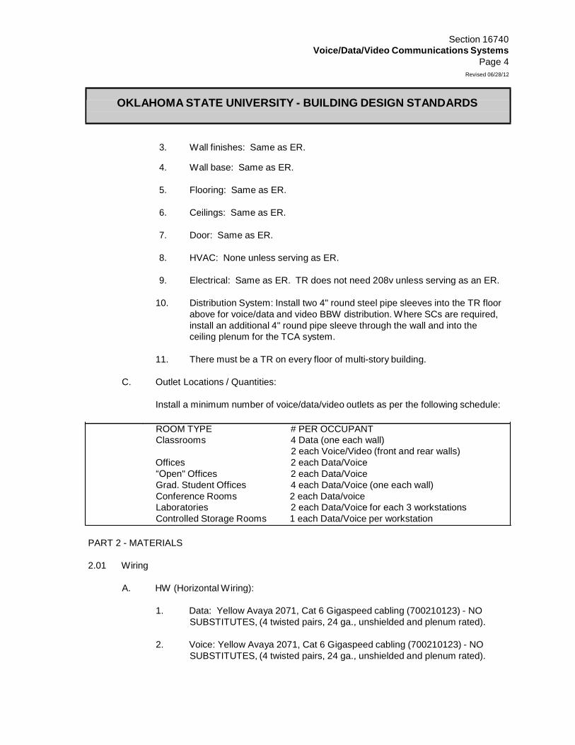
3.
Wall finishes: Same as ER.
4. Wall base: Same as ER.
5.
Flooring: Same as ER.
6.
Ceilings: Same as ER.
7.
Door: Same as ER.
8.
HVAC: None unless serving as ER.
9.
Electrical: Same as ER. TR does not need 208v unless serving as an ER.
10.
Distribution System: Install two 4" round steel pipe sleeves into the TR floor
above for voice/data and video BBW distribution. Where SCs are required,
install an additional 4" round pipe sleeve through the wall and into the
ceiling plenum for the TCA system.
11.
There must be a TR on every floor of multi-story building.
C.
Outlet
Locations / Quantities:
Install
a minimum number of voice/data/video outlets as per the following schedule:
ROOM TYPE # PER OCCUPANT
Classrooms 4 Data (one each wall)
2 each Voice/Video (front and rear walls)
Offices 2 each Data/Voice
“Open" Offices 2 each Data/Voice
Grad. Student Offices 4 each Data/Voice (one each wall)
Conference Rooms 2 each Data/voice
Laboratories 2 each Data/Voice for each 3 workstations
Controlled Storage Rooms 1 each Data/Voice per workstation
PART 2 - MATERIALS
2.01 Wiring
A. HW (Horizontal Wiring):
1. Data: Yellow Avaya 2071, Cat 6 Gigaspeed cabling (700210123) - NO
SUBSTITUTES, (4 twisted pairs, 24 ga., unshielded and plenum rated).
2. Voice: Yellow Avaya 2071, Cat 6 Gigaspeed cabling (700210123) - NO
SUBSTITUTES, (4 twisted pairs, 24 ga., unshielded and plenum rated).

Section 16740
Voice/Data/Video Communications Systems
Page 5
Revised 06/28/12
OKLAHOMA STATE UNIVERSITY - BUILDING DESIGN STANDARDS
3. Fiber: (If required): Systimax indoor/outdoor 48 singlemode fiber with
drywater block compound or equivalent. Fibers will be terminated using
Systimax SC connectors.
B. BBW and TCA (Building Backbone Wiring and Tie Cable):
1. Voice/Data: All fiber backbone will be Systimax indoor/outdoor 48
singlemode fiber with a dry water block system or equivalent. All Fibers will
be terminated using Systimax SC connectors.
C. Outlets:
1. TO: Empty, recessed, single-gang outlet box (double-gang outlet boxes
when HW fiber is required); wall or floor mounted or installed in power
poles. TOs shall be 4” X 4” x 1-3/4”.
2. Faceplates: All faceplate will be Systimax electrical ivory Triplex
(108168519) or Quadplex (108168550). All vacant positions will be covered
using the Systimax M-series dust cover (107067860).
3. Communication Jacks: Jacks will be Orange systimax MGS 400 Cat 6
jacks (700206683). Jacks will be terminated using the 568B wiring
configuration.
D. Data Racks and Terminations:
1. Rack: Data rack will be 7’ tall 19” wide freestanding rack. Rack will be
systimax (108527441) or equivalent.
2. Wire Management: All racks will have Vertical wire management and will
be Systimax GV 100A 6” W x 6.76” D x 7’ (108527560) or equivalent.
3. Patch Panel: All rack will use the Systimax Patchmax GS3 (700173776)
patch panel will use the 6 port RJ45 module (700173776) on which all
horizontal data wiring will be terminated using the 568B wiring configuration
and dressed in using Velcro. All patch panels will be located just under the
fiber termination unit on each rack.
4. Fiber Shelf: Fibers will be connected in a Systimax Fiber optic modular
shelf and can vary in size depending on number of fibers entering the shelf.
5. Data whips: Data whips will be Systimax light blue 6’ Cat 6 and will be
contractor-provided and installed by OSU.
E. Telephone Terminations:
1. All telephones will terminate in same location as data.

Section 16740
Voice/Data/Video Communications Systems
Page 6
Revised 06/28/12
OKLAHOMA STATE UNIVERSITY - BUILDING DESIGN STANDARDS
F. Data Terminations:
1. Telecom Room: All Data horizontal cabling upon entering the Telecom
room will route from the entry point to the data rack using a Cabofil cable
tray (FC54/300EZ) or equivalent.
2.02 Grounding Bar
Install copper grounding bar (12"x 1" x 1/4" with 1/4" holes at 1" on center and insulated wall
brackets) connected to the building earth ground access point for all communications
equipment. The resistance from the MTRITC/SC to the building ground shall be 5 OHM or
less. Wire shall be not be less than 4mm (0.162 inches) in diameter or #6 AWG insulated
wire. If the resistance cannot be met next larger size wire shall be used. Grounds shall not
be run on 90-degree angles. All bends shall be sweeping bends.
PART 3 - INSTALLATION & ACCEPTANCE
3.01 General
A. All power outlets in ER/SC/TR shall be grounded, on dedicated circuits, and
connected to emergency power system.
B. Conduit is not required where HW wiring is run horizontally above ceilings. Wiring
support method shall be independent of utilities such as conduits, pipes, ceiling
support systems, and shall not be laid directly on top of suspended ceiling panels or
through elevator shafts. The support system used shall adhere to all appropriate
NEC, EIA/TIA and BICSI standards.
C. Conduit, cable tray, wire, etc., must be concealed from view in occupied
areas unless approved by Oklahoma State University Architecture Services.
D. All conduit turns must be the long sweep type.
E. A pull wire equal to a #12 AWG shall be installed in all empty conduits.
F. Conduit entering equipment rooms shall have grounding bushings.
G. Above grade EC point of entries are not allowed unless approved by
Oklahoma State University Architecture Services.
H. Open ends of empty conduit or sleeves shall be capped and fireproofed
for future access.
I. Install pull boxes in all conduit runs where more than two 90-degree turns are
required. Size boxes so that the minimum bend radius specified for the fiber used
will not exceed industry standards.

Section 16740
Voice/Data/Video Communications Systems
Page 7
Revised 06/28/12
OKLAHOMA STATE UNIVERSITY - BUILDING DESIGN STANDARDS
J. Provide mechanical type sleeves in basement walls where the EC enters the
building through core-drilled openings or cast-in-place sleeves.
K. All wiring runs shall be continuous from TR or SC to TO or VO. No splices allowed.
L. All wiring penetrating any wall shall be adequately protected using some form of UL listed sleeve. The penetration shall be forestopped using an approved, tested firestop system assembly.
M. All installations shall meet the conformance standards of NEC, BICSI, ANSI/TIA/EIA
and all other industry standards.
N. All wiring of the TRs and ERs shall be through one side of the room if possible, if not
contact owner for equipment locations.
O. When running horizontal cable between floors, sleeves between floors shall be
aligned vertically.
P. All organizations pulling in wire shall have an RCDD on staff to supervise the work
being done.
Q. All contractors installing telephone and data wiring shall be required to have the
ability to provide the 20-year Systimax Warranty.
R. All Telephone and Data shall not share the same run with any other media (e.g.
Cable TV). No BAS systems shall share the communications run.
S. Cables crossing over hard ceiling of more than 15 foot shall be ran in conduit large
enough for future use by the University.
T. All J-hooks shall be installed every 48 inches. If there is sagging in the cable
between the J-hooks install additional J-hooks.
U. Accepted contractor will provide, install, and terminate all copper and fiber.
V. All communication outlets will be labeled according to what is existing. If none are
existing Telephone jacks will be labeled according to floor level and in numerical
order i.e. (4th
floor would start 401, 402, and so on). Data jacks will be labeled by
room number and then amount of jacks in room i.e. 401-1, 401-2.
3.02 Wiring
A. Horizontal Wiring (HW): Horizontal runs shall be installed using a star system
layout.
1. Wiring shall be installed with 10' - 0" pig tails at each end of each run.

Section 16740
Voice/Data/Video Communications Systems
Page 8
Revised 06/28/12
OKLAHOMA STATE UNIVERSITY - BUILDING DESIGN STANDARDS
B. Building Backbone Wiring (BBW):
1. Data cables shall be extended to the closest TR, and run from the TR to all
other TRs or SCs.
2. All Fiber backbone cabling shall feed in a continuous run from each data
room back to the Main Data room for termination. Contact owner for
specifics.
3.03 Outlets
A. Telecommunications Outlets (TO):
1. Mount with bottom of outlet box at 15” A.F.F.
2. Install one 1/2" conduit (3/4" if fiber is included) from the outlet box to an
accessible ceiling plenum.
3. Provide one 110V duplex outlet adjacent to each TO.
3.04 Outside Plant
A. Conduit:
1. The Owner will specify conduit sizes. At a minimum there will need to be
two-2” conduits.
2. All conduits containing fiber optic cabling shall be buried a minimum of 36”.
3. If a trenching method is used to install the conduit(s), the trench shall be
filled with a minimum of 12” of sand or concrete.
4. All conduits shall contain a direct burial rated tracer wire (#12 AWG
minimum) with a Mule tape pull wire.
6. All 90 degree bends shall be steel sweeps, wrapped with PVC tape.
7. Orange cut tape shall be placed at a minimum of 12 inches above all buried
cable or conduit.
B. Pull Boxes:
1. A maximum of one 90-degree bend shall be allowed between pull
boxes.
2. All boxes shall be installed with lid at grade level.
Section 16740
Voice/Data/Video Communications Systems
Page 9
Revised 06/28/12
OKLAHOMA STATE UNIVERSITY - BUILDING DESIGN STANDARDS
3. All lids shall be properly labeled to indicate the contents of the pull
box.
4. Precast concrete pull boxes: 3’-0” x 5’-0” x 3’-0” I.D., with 3’-0” x 5’-0” double
door H-20 lids. Substitutions must be approved by the Owner prior to bid.
a. Specification Criteria:
1. 4500 pound concrete with grade 60 steel.
2. HS-20 wheel load.
3. Thinwall window knockouts, each wall, bottom center.
4. 6” wall thickness.
b. Frame and Cover Specifications:
1. H-20 3’-0” x 5’-0” cover.
2. Torsion assist doors.
3. Hot dipped galvanized.
4. Bolt to the top of the box design.
c. Suggested Vendor List:
1. Hughes Supply American Industrial Pre-cast Products
3501 South Interstate 35 West
Alvarado, Texas 76009
800.536.2951
2. Oldcastle Precast
1100 Heritage Parkway
Mansfield, Texas 76063
817.477.2914
3.05 Cabling System Inspection
OSU IT will conduct periodic inspections of the cable installation prior to the completion of
project to ensure that the cabling systems meet the OSU requirements any cables that are
damaged during installation or otherwise ran inappropriately regardless of the testing will be
re-pulled at the Contractor’s expense. OSU IT will be contacted for the final inspection or
walkthrough.
Section 16740
Voice/Data/Video Communications Systems
Page 10
Revised 06/18/12
OKLAHOMA STATE UNIVERSITY - BUILDING DESIGN STANDARDS
3.06 Coordination/Review/Approval
At the end of each design phase, the work completed shall be submitted to OSU
Architecture Services for coordination of the review/approval process. The IT, TSD, Client,
and Physical Plant will furnish design standards, changes or modifications to the standards
and review/approve all submittals.
4.00 Approved contractor list to install Systimax cabling for OSU- STILLWATER campus.
SYSTIMAX Tulsa area Business Partners:
Lanlynx - Bill Morgan (918) 728-6002 [email protected] Sagenet - Jeremy Carter (918) 625-4459 [email protected] Electra Link- Mark Harrison (918) 269-2212 [email protected] Wachter- Mike Osten (918) 340-0238 [email protected]
SYSTIMAX Oklahoma City area Business Partners
Infosys - Michael Burchette (405) 525-9001 [email protected] Dane - Marty Kelso (405) 412-1828 [email protected]
Electra Link- Bruce Conley (405)305-4252 [email protected]
Telco Supply Greg Taylor (580) 221 - 3663 Lori Garland, Territory Manager CommScope, Oklahoma, Phone: 918-407-6144

Section 16740
Voice/Data/Video Communications Systems
Page 11
Revised 06/18/12
OKLAHOMA STATE UNIVERSITY - BUILDING DESIGN STANDARDS
Section 16740
Voice/Data/Video Communications Systems
Page 12
Revised 06/18/12
OKLAHOMA STATE UNIVERSITY - BUILDING DESIGN STANDARDS

Section 16740
Voice/Data/Video Communications Systems
Page 13
Revised 06/18/12
OKLAHOMA STATE UNIVERSITY - BUILDING DESIGN STANDARDS
END OF SECTION 16740