OKALOOSA COUNTY WATER AND SEWER · Okaloosa County Water and Sewer i Revision 00 Okaloosa County,...
326
OKALOOSA COUNTY WATER AND SEWER OKALOOSA COUNTY, FLORIDA STANDARD SPECIFICATIONS AND DESIGN MANUAL JUNE 2007
Transcript of OKALOOSA COUNTY WATER AND SEWER · Okaloosa County Water and Sewer i Revision 00 Okaloosa County,...

OKALOOSA COUNTY WATER AND SEWER
OKALOOSA COUNTY, FLORIDA
STANDARD SPECIFICATIONS AND DESIGN MANUAL
JUNE 2007

OKALOOSA COUNTY WATER AND SEWER
TABLE OF CONTENTS
Okaloosa County Water and Sewer Revision 00 Okaloosa County, Florida Date: June 2007
ABBREVIATIONS/DEFINITIONS ............................................................................................ i SECTION 1 INTRODUCTION 1.1 PURPOSE............................................................................................................ 1-1 1.2 DESCRIPTION OF DESIGN MANUAL ........................................................... 1-1 1.3 UPDATES TO THE ENGINEERING DESIGN MANUAL .............................. 1-1 SECTION 2 GENERAL INTRODUCTION 2.1 PURPOSE............................................................................................................ 2-1 2.2 APPLICABILITY................................................................................................ 2-1 2.3 CERTIFICATION REQUIREMENTS ............................................................... 2-1 2.3.1 Engineering Design.................................................................................. 2-1 2.3.2 Survey ...................................................................................................... 2-1 2.4 SUBMITTAL REQUIREMENTS ...................................................................... 2-1 2.5 SUBMITTAL, REVIEW AND APPROVAL ..................................................... 2-2 2.5.1 Applicability ............................................................................................ 2-2 2.5.2 Submittals ................................................................................................ 2-2 2.5.3 Restrictions .............................................................................................. 2-3 2.6 NOTIFICATION OF CONSTRUCTION ........................................................... 2-3 2.7 MAINTENANCE PERIOD................................................................................. 2-3 2.8 RESPONSIBLE CHARGE OF CONSTRUCTION............................................ 2-3 2.9 DISPUTES, ERRORS, AND OMISSIONS ........................................................ 2-3 2.10 CHANGE OF CONDITIONS/MISREPRESENTATIONS/CHANGE IN THE
WORK. ................................................................................................................ 2-4 SECTION 3 DRAFTING STANDARDS 3.1 PURPOSE............................................................................................................ 3-1 3.2 DRAWING REQUIREMENTS ......................................................................... 3-1 3.2.1 Sheet Size................................................................................................. 3-1 3.2.2 Electronic Submittals ............................................................................... 3-1 3.2.3 Title Block Information ........................................................................... 3-1 3.2.4 Horizontal and Vertical Scales................................................................. 3-2 3.2.5 Graphic Scale ........................................................................................... 3-2 3.2.6 Shading .................................................................................................... 3-2 3.2.7 Lettering................................................................................................... 3-2 3.2.8 Utility Locations ...................................................................................... 3-2 3.3 DRAWING PACKAGE ...................................................................................... 3-3 3.3.1 Title Sheet Requirements......................................................................... 3-3

TABLE OF CONTENTS
Okaloosa County Water and Sewer Revision 00 Okaloosa County, Florida Date: June 2007
3.3.2 Plat/Lotting Layout .................................................................................. 3-3 3.3.3 Plan and Profile Sheet Requirements....................................................... 3-4 3.3.4 Detail Sheet .............................................................................................. 3-6 SECTION 4 FINAL RECORD DRAWINGS/AS-BUILTS 4.1 PURPOSE............................................................................................................ 4-1 4.2 GENERAL........................................................................................................... 4-1 4.3 PROCESS ............................................................................................................ 4-1 4.4 FINAL RECORD DRAWINGS/AS-BUILT REQUIREMENTS....................... 4-1 4.5 SURVEYS ........................................................................................................... 4-2 4.6 CERTIFICATION ............................................................................................... 4-2 4.7 AUDIT OF RECORD DRAWINGS ................................................................... 4-3 SECTION 5 SURVEYING 5.1 PURPOSE............................................................................................................ 5-1 5.2 GENERAL STANDARDS.................................................................................. 5-1 5.3 HORIZONTAL AND VERTICAL CONTROL ................................................. 5-1 5.3.1 Datums ..................................................................................................... 5-1 5.3.2 Project Control Points .............................................................................. 5-1 5.4 HORIZONTAL AND VERTICAL ACCURACY .............................................. 5-2 5.5 INFORMATION SHOWN ON THE PLANS..................................................... 5-2 5.6 ADDITIONAL DATA AND INFORMATION.................................................. 5-3 5.6.1 Field Profiles............................................................................................ 5-3 5.6.2 Cross-Sections Topography and Planimetry............................................ 5-3 5.6.3 Utilities..................................................................................................... 5-3 5.6.4 Highways and Railroads .......................................................................... 5-3 5.6.5 Existing Rights-of-Way, Easements, and Property Lines........................ 5-3 5.6.6 Sanitary Service connection Survey ........................................................ 5-4 SECTION 6 EASEMENTS 6.1 PURPOSE............................................................................................................ 6-1 6.2 GENERAL........................................................................................................... 6-1 6.2.1 Acquisition............................................................................................... 6-1 6.2.2 Location ................................................................................................... 6-1 6.2.3 Certification Criteria ................................................................................ 6-1 6.2.4 Restrictions .............................................................................................. 6-1 6.2.5 Schedule................................................................................................... 6-2 6.3 EASEMENT WIDTHS........................................................................................ 6-2 6.4 PLATTED EASEMENTS ................................................................................... 6-3 6.5 DEEDED EASEMENTS BY DOCUMENT....................................................... 6-3 6.5.1 Legal Description..................................................................................... 6-3 6.5.2 Easement Location Sketch....................................................................... 6-3 6.6 EASEMENT ENCROACHMENT...................................................................... 6-4

ENGINEERING DESIGN MANUAL
Okaloosa County Water and Sewer Revision 00 Okaloosa County, Florida Date: June 2007
6.7 PROPERTY SERVICE CONNECTION EASEMENT ...................................... 6-4 6.8 FIELD VERIFICATION ..................................................................................... 6-4 SECTION 7 WATER DISTRIBUTION SYSTEMS 7.1 PURPOSE............................................................................................................ 7-1 7.2 RECLAIMED/REUSE WATER PIPING SYSTEM........................................... 7-1 7.3 GENERAL LOCATION CRITERIA.................................................................. 7-1 7.3.1 Water Main Location ............................................................................... 7-1 7.3.2 Water Lateral Location ............................................................................ 7-2 7.3.3 Fire Hydrant Location.............................................................................. 7-2 7.3.4 Valve Location......................................................................................... 7-3 7.3.5 Meter and Vault/Meter Box Location...................................................... 7-3 7.4 DESIGN CRITERIA. .......................................................................................... 7-3 7.4.1 Fire Flow Requirements........................................................................... 7-4 7.4.2 Acquisition............................................................................................... 7-4 7.4.3 Pressure and Friction Loss ....................................................................... 7-4 7.4.4 Diameter................................................................................................... 7-4 7.4.5 Allowable Deflection of Ductile-Iron Pipe Joints ................................... 7-5 7.4.6 Flanged Pipe............................................................................................. 7-5 7.4.7 Fire Hydrants ........................................................................................... 7-5 7.4.8 Dead Ends ................................................................................................ 7-6 7.4.9 Main Terminus Extensions ...................................................................... 7-6 7.4.10 Separation of Water and Sewer Mains..................................................... 7-7 7.4.11 Water Main/Sewer Crossing .................................................................... 7-8 7.4.12 Water Main/Storm Water Crossing ......................................................... 7-8 7.4.13 Laterals..................................................................................................... 7-8 7.4.14 Lateral Size and Maximum Number of Water Meters............................. 7-8 7.4.15 Thrust Restraint........................................................................................ 7-8 7.4.16 Operation of Existing Water Distribution Facilities ................................ 7-9 7.4.17 Trench Preparation................................................................................... 7-9 7.4.18 Dewatering............................................................................................. 7-10 7.4.19 Pipe Line Construction .......................................................................... 7-11 7.4.20 Encasement Requirements ..................................................................... 7-12 7.4.21 Cross Connection Control...................................................................... 7-13 7.5 MATERIAL REQUIREMENTS....................................................................... 7-13 7.5.1 Inspection of Materials .......................................................................... 7-13 7.5.2 Pipe ....................................................................................................... 7-13 7.5.3 Fittings ................................................................................................... 7-14 7.5.4 Valves .................................................................................................... 7-15 7.5.5 Backflow Prevention Devices................................................................ 7-16 7.5.6 Valve Boxes ......................................................................................... 7-16 7.5.7 Tapping Sleeves ..................................................................................... 7-17 7.5.8 Tapping Valves ...................................................................................... 7-18 7.5.9 Encasements........................................................................................... 7-18 7.5.10 Fire Hydrants ......................................................................................... 7-19
TABLE OF CONTENTS
Okaloosa County Water and Sewer Revision 00 Okaloosa County, Florida Date: June 2007
7.5.11 Corporation Stops .................................................................................. 7-19 7.5.12 Service Saddle/Sleeve (¾" through 2") ................................................. 7-20 7.5.13 Grip Joint Coulp..................................................................................... 7-20 7.5.14 Grip Pack Joint Coulp............................................................................ 7-21 7.5.15 Curb Stops.............................................................................................. 7-21 7.5.16 Straight Pipe Couplings (¾" through 2") ............................................... 7-21 7.5.17 Mechanical Restraint ............................................................................. 7-22 7.5.18 All Thread Rods and Eye Bolts ............................................................. 7-24 7.5.19 Backfill................................................................................................... 7-24 SECTION 8 WASTE WATER COLLECTION 8.1 PURPOSE............................................................................................................ 8-1 8.2 REGIONAL PLANNING AND COORDINATION .......................................... 8-1 8.3 GENERAL LOCATION CRITERIA.................................................................. 8-1 8.3.1 Gravity Sewer Alignment Criteria ........................................................... 8-3 8.3.2 Sewer Force Main Alignment Criteria..................................................... 8-4 8.4 DESIGN FLOW DETERMINATION ................................................................ 8-3 8.4.1 Drainage Map........................................................................................... 8-6 8.4.2 Design Flow . ........................................................................................... 8-6 8.4.3 Hydraulic Design Criteria ........................................................................ 8-5 8.5 DESIGN CRITERIA ........................................................................................... 8-6 8.5.1 Sewer Pipe ............................................................................................... 8-6 8.5.2 Manholes.................................................................................................. 8-7 8.5.3 Laterals..................................................................................................... 8-9 8.5.4 Flotation ................................................................................................... 8-9 8.5.5 Concrete Encasements ........................................................................... 8-10 8.5.6 Encasement Requirements ..................................................................... 8-10 8.5.7 Railroad Crossings ................................................................................. 8-11 8.5.8 Highway Crossings ................................................................................ 8-11 8.5.9 Interruption of Existing Sewer Service.................................................. 8-12 8.5.10 Trench Preparation................................................................................. 8-12 8.5.11 Pipe Line Construction .......................................................................... 8-13 8.6 MATERIAL REQUIREMENTS....................................................................... 8-14 8.6.1 Inspection of Materials .......................................................................... 8-14 8.6.2 Pipe ........................................................................................................ 8-14 8.6.3 Laterals................................................................................................... 8-15 8.6.4 Fittings ................................................................................................... 8-15 8.6.5 Couplings and Connectors ..................................................................... 8-15 8.6.6 Epoxy Coatings...................................................................................... 8-15 8.6.7 Manholes................................................................................................ 8-16 8.6.8 Encasement Requirements ..................................................................... 8-17 8.6.9 Backfill................................................................................................... 8-18 8.6.10 Valves ................................................................................................... 8-18 8.6.11 Valve Boxes ........................................................................................... 8-19
ENGINEERING DESIGN MANUAL
Okaloosa County Water and Sewer Revision 00 Okaloosa County, Florida Date: June 2007
SECTION 9 SEWER TESTING AND INSPECTION 9.1 PURPOSE............................................................................................................ 9-1 9.2 GENERAL........................................................................................................... 9-1 9.2.1 Visual Inspection ..................................................................................... 9-1 9.2.2 Low Pressure Air Test ............................................................................. 9-1 9.2.3 Vacuum Testing of Manholes.................................................................. 9-4 9.3 SEQUENCE OF TESTING................................................................................. 9-5 9.4 TEST FAILURE .................................................................................................. 9-5 9.5 MANDREL EQUIPMENT.................................................................................. 9-5 9.6 AIR/VACUUM TEST EQUIPMENT ................................................................. 9-5 NEW CONSTRUCTION INSPECTION CHECKLIST ................................................. 9-6 SECTION 10 WATER TESTING AND INSPECTION 10.1 PURPOSE.......................................................................................................... 10-1 10.2 GENERAL......................................................................................................... 10-1 10.3 VISUAL INSPECTION..................................................................................... 10-1 10.4 HYDROSTATIC TESTING.............................................................................. 10-1 10.4.1 Pressure Test Restrictions ...................................................................... 10-2 10.4.2 Air Testing of Tapping Sleeve............................................................... 10-2 10.4.3 Hydrostatic Test Procedure.................................................................... 10-2 10.5 DISINFECTION AND BACTERIOLOGICAL TESTING .............................. 10-4 10.6 FINAL INSPECTION ....................................................................................... 10-4 10.7 TEST FAILURE ................................................................................................ 10-4 10.8 PRESSURE TEST EQUIPMENT ..................................................................... 10-4 NEW CONSTRUCTION INSPECTION CHECKLIST ............................................... 10-5 SECTION 11 PUMP STATIONS 11.1 INTRODUCTION ............................................................................................. 11-1 11.2 SERVICE AREA PLANNING.......................................................................... 11-2 11.2.1 Establishing Service............................................................................... 11-2 11.2.2 Projecting Service Area Wastewater Flows........................................... 11-3 11.3 PUMP STATION DESIGN REQUIREMENTS ............................................... 11-3 11.3.1 Introduction............................................................................................ 11-3 11.3.2 Size Criteria ........................................................................................... 11-4 11.3.3 Wet Well ................................................................................................ 11-4 11.3.4 Submersible Pumps................................................................................ 11-4 11.3.5 Valve Pit................................................................................................. 11-4 11.3.6 Site Dimensions ..................................................................................... 11-5 11.4 SUBMITTALS .................................................................................................. 11-5 11.4.1 Submittal Items ...................................................................................... 11-5 11.5 GUIDELINE SPECIFICATIONS FOR CONSTRUCTION ............................ 11-7 11.5.1 Valve Housing Box................................................................................ 11-7 11.5.2 Wet Well ................................................................................................ 11-7

TABLE OF CONTENTS
Okaloosa County Water and Sewer Revision 00 Okaloosa County, Florida Date: June 2007
11.5.3 Plates, Sheets, and Shapes ..................................................................... 11-9 11.5.4 Submersible Pumping Equipment........................................................ 11-10 11.5.5 Electrical .............................................................................................. 11-12 11.5.6 General Requirements.......................................................................... 11-13 SECTION 12 VARIANCES 12.1 PURPOSE.......................................................................................................... 12-1 12.2 GENERAL......................................................................................................... 12-1 DIVISION 1 GENERAL REQUIREMENTS SECTION 01570 MAINTENANCE AND PROTECTION OF TRAFFIC SECTION 01710 CLEANING SECTION 01730 OPERATION AND MAINTENANCE DATA DIVISION 2 SITE CONSTRUCTION SECTION 02110 CLEARING SECTION 02220 EXCAVATION AND BACKFILL SECTION 02512 BITUMINOUS PAVING SECTION 02606 MANHOLES DIVISION 3 CONCRETE SECTION 03300 CONCRETE DIVISION 9 FINISHES SECTION 09900 PAINTING DIVISION 11 EQUIPMENT SECTION 11145 LIFT STATION SPECIFICATIONS DIVISION 15 MECHANICAL SECTION 15051 BURIED PIPING SECTION 15052 EXPOSED PIPING SECTION 15100 VALVES, 4-INCH AND LARGER DIVISION 16 ELECTRICAL SECTION 16600 INTEGRATED SPECIFICATION SECTION 16610 TRANSIENT VOLTAGE SURGE SUPPRESSION (TVSS)
EQUIPMENT

ENGINEERING DESIGN MANUAL
Okaloosa County Water and Sewer Revision 00 Okaloosa County, Florida Date: June 2007
DRAWINGS MISCELLANEOUS DETAILS
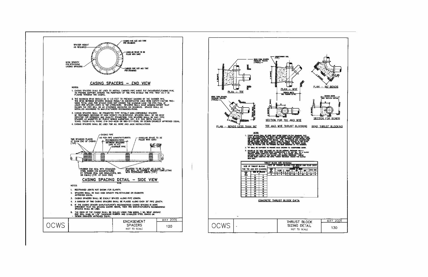
PIPE BEDDING REQUIREMENTS ..............................................................................100 TRENCH BACKFILL ABOVE PIPE ZONE .................................................................110 ENCASEMENT SPACERS ............................................................................................120 THRUST BLOCK SIZING DETAIL..............................................................................130 TYPICAL STREET LAYOUT........................................................................................160
WATER DISTRIBUTION DETAILS
FIRE HYDRANT DETAIL.............................................................................................200 DOUBLE CHECK BACKFLOW ...................................................................................230 WATER SERVICE CONNECTION...............................................................................250
SANITARY SEWER DETAILS
PRECAST CONCRETE MANHOLE.............................................................................300 PRECAST DROP MANHOLE .......................................................................................310 SHALLOW SERVICE LATERAL .................................................................................320 DEEP SERVICE LATERAL........................................................................................320A
STANDARD PUMP STATION DETAILS
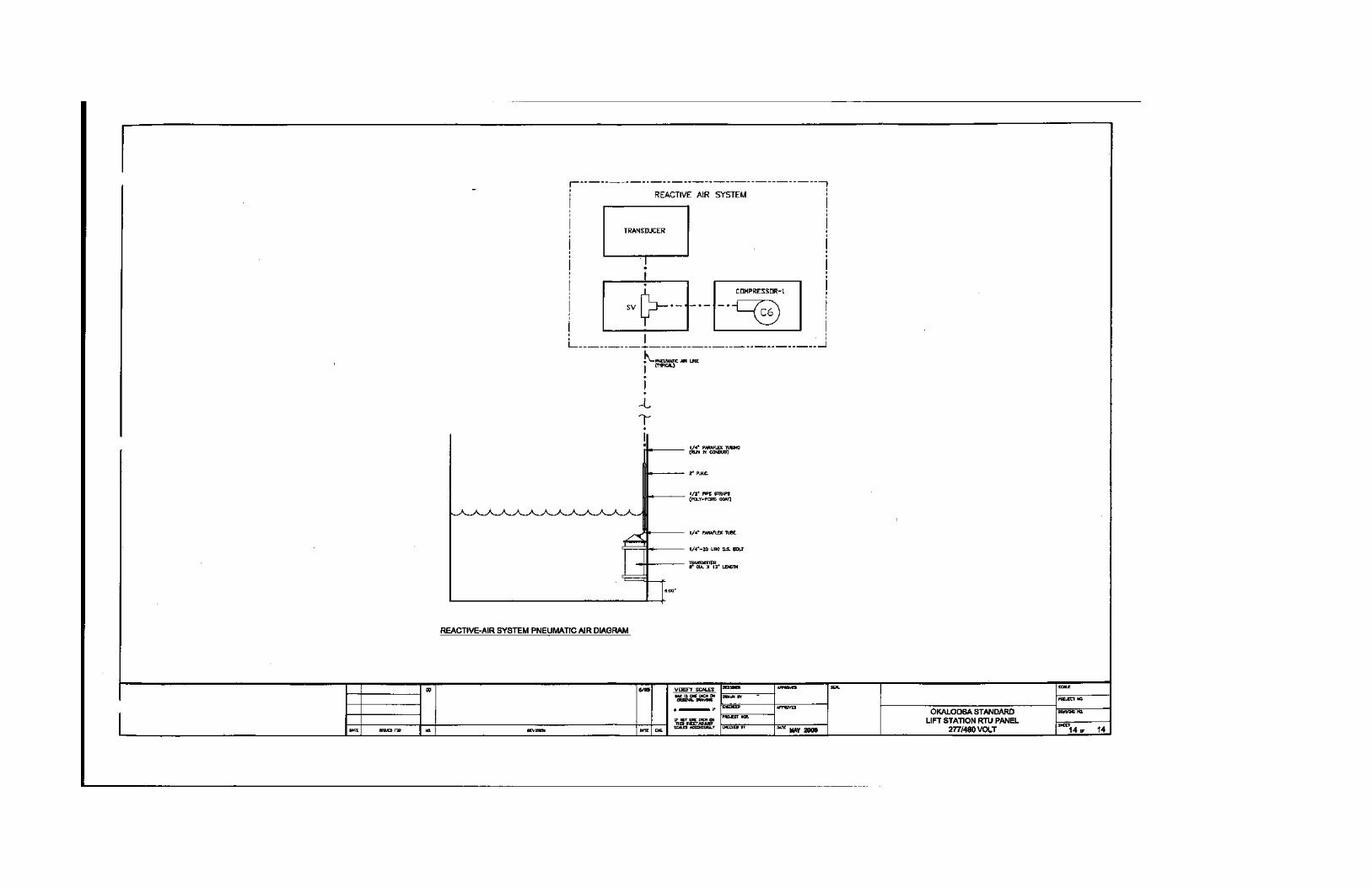
GENERAL PUMP STATION SITE PLAN........................................................................1 GENERAL PUMP STATION SECTION VIEW................................................................2 PUMP STATION RTU PANEL 120/240 VOLT................................................................3 PUMP STATION RTU PANEL 120/240 VOLT................................................................4 PUMP STATION RTU PANEL 120/240 VOLT................................................................5 PUMP STATION RTU PANEL 120/240 VOLT................................................................6 PUMP STATION RTU PANEL 120/240 VOLT................................................................7 PUMP STATION RTU PANEL 120/240 VOLT................................................................8 PUMP STATION RTU PANEL 277/480 VOLT................................................................9 PUMP STATION RTU PANEL 277/480 VOLT..............................................................10 PUMP STATION RTU PANEL 277/480 VOLT..............................................................11 PUMP STATION RTU PANEL 277/480 VOLT..............................................................12 PUMP STATION RTU PANEL 277/480 VOLT..............................................................13 PUMP STATION RTU PANEL 277/480 VOLT..............................................................14


OKALOOSA COUNTY WATER AND SEWER
ABBREVIATIONS/DEFINITIONS
Okaloosa County Water and Sewer i Revision 00 Okaloosa County, Florida Date: June 2007
ABBREVIATIONS/DEFINITIONS 1. And/Or � An option of OCWS Engineer or representative. 2. Approval � Approval of Plans - A review by OCWS Engineer of Plans, stating
that the plans are in substantial compliance with OCWS specifications. 3. ASCE � American Society of Civil Engineers. 4. ASTM � American Society for Testing and Materials. 5. AWWA � American Water Works Association. 6. Contractor � The individual, partnership, firm, corporation, or any acceptable
combination thereof contracting for the performance of the prescribed work. 7. Connection Costs – 8. Corporation Stop � A special brass valve designed for insertion in the water
mains to which can be attached to the service line of the Owner. 9. CRF – Concurrency Review Form 10. Curb Stop � A special brass valve designed for the installation between the
service line and Owner’s plumbing, and to be used only by OCWS for conveniently turning water on and off.
11. Developer - The party or parties paying for the installation of the water main and appurtenances.
12. Developer’s Engineer � the Professional Engineer (licensed in the State of Florida) employed by the Developer who is responsible for the submission of engineering plans and project development.
13. Distribution System � The pipes, mains, valves, fittings and other related appliances through which water is transmitted to customers of OCWS.
14. Drop Manholes � A precast, concrete, structure used where one sewer joins another several feet below. The lower sewer enters the manhole at the bottom in the usual manner. The upper sewer, however, turns down sharply just outside the manhole and enters it at the bottom. To permit cleaning of the upper sewer from the manhole, the upper sewer also extends to the manhole at constant slope past the sharp drop through which the sewage flows.
15. Easement � A right to use or control the property of another for designated purposes.
16. FDEP – Florida Department of Environmental Protection 17. FDOT – Florida Department of Transportation 18. Inspector � OCWS' authorized representative assigned to make detailed
inspection of contract performance. 19. Job Site � The location of the project where water mains and appurtenances are to
be installed. 20. Lateral � A sewer line that connects to the main sewer and terminates at or near
the property line or easement.
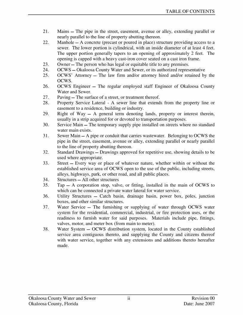
TABLE OF CONTENTS
Okaloosa County Water and Sewer ii Revision 00 Okaloosa County, Florida Date: June 2007
21. Mains � The pipe in the street, easement, avenue or alley, extending parallel or nearly parallel to the line of property abutting thereon.
22. Manhole � A concrete (precast or poured in place) structure providing access to a sewer. The lower portion is cylindrical, with an inside diameter of at least 4 feet. The upper portion generally tapers to an opening of approximately 2 feet. The opening is capped with a heavy cast-iron cover seated on a cast iron frame.
23. Owner � The person who has legal or equitable title to any premises. 24. OCWS � Okaloosa County Water and Sewer, or its authorized representative 25. OCWS’ Attorney � The law firm and/or attorney hired and/or retained by the
OCWS. 26. OCWS Engineer � The regular employed staff Engineer of Okaloosa County
Water and Sewer. 27. Paving � The surface of a street, or treatment thereof. 28. Property Service Lateral - A sewer line that extends from the property line or
easement to a residence, building or industry. 29. Right of Way � A general term denoting lands, property or interest therein,
usually in a strip acquired for or devoted to transportation purposes. 30. Service Main � The temporary supply pipe installed on streets where no standard
water main exists. 31. Sewer Main � A pipe or conduit that carries wastewater. Belonging to OCWS the
pipe in the street, easement, avenue or alley, extending parallel or nearly parallel to the line of property abutting thereon.
32. Standard Drawings � Drawings approved for repetitive use, showing details to be used where appropriate.
33. Street � Every way or place of whatever nature, whether within or without the established service area of OCWS open to the use of the public, including streets, alleys, highways, park, or other road, and all public places.
34. Structures � All other structures 35. Tap � A corporation stop, valve, or fitting, installed in the main of OCWS to
which can be connected a private water lateral for water service. 36. Utility Structures � Catch basin, drainage basin, power box, poles, junction
boxes, and other similar structures. 37. Water Service � The furnishing or supplying of water through OCWS water
system for the residential, commercial, industrial, or fire protection uses, or the readiness to furnish water for said purposes. Materials include pipe, fittings, valves, motor, and meter box (from main to meter).
38. Water System � OCWS distribution system, located in the County established service area contiguous thereto, and supplying the County and citizens thereof with water service, together with any extensions and additions thereto hereafter made.

SECTION 1
INTRODUCTION


OKALOOSA COUNTY WATER AND SEWER
SECTION 1 TABLE OF CONTENTS
Okaloosa County Water and Sewer Revision 00 Okaloosa County, Florida Date: June 2007
SECTION 1 INTRODUCTION 1.1 PURPOSE....................................................................................................1 1.2 DESCRIPTION OF DESIGN MANUAL ...................................................1
1.3 UPDATES TO THE ENGINEERING DESIGN MANUAL ......................1


OKALOOSA COUNTY WATER AND SEWER
SECTION 1 INTRODUCTION
Okaloosa County Water and Sewer 1-1 Revision 00 Okaloosa County, Florida Date: June 2007
1.1 PURPOSE
The purpose of this document is to outline Okaloosa County Water and Sewer (OCWS) minimum requirements for the design, construction, and installation of potable water distribution and wastewater collection systems within OCWS' jurisdiction.
1.2 DESCRIPTION OF DESIGN MANUAL
This manual identifies a single set of standards, submittal requirements, and approval procedures to be used in the evaluation, design, and construction of projects. This manual is not intended to serve as a step-by-step instructional handbook nor can this manual address every situation, which may arise during the course of construction. The application of sound engineering principles and judgment, combined with the information contained herein, are necessary in order to successfully design potable water distribution and wastewater collection projects.
1.3 UPDATES TO THE ENGINEERING DESIGN MANUAL
This manual is intended to be a dynamic document. As design criteria and technology evolve, the manual will require revisions and modifications. As changes are made, supplements or revisions will be forwarded to the registered holder of each manual. It will be each registered holder’s responsibility to maintain a current manual. Comments and suggestions concerning the content and format of the design manual are welcome. Please submit your comments or suggestions to: Okaloosa County Water and Sewer Engineering Department 1804 Lewis Turner Boulevard, Suite 300 Fort Walton Beach, Florida 32547 [email protected]
+++ END OF SECTION +++


SECTION 2
GENERAL INFORMATION


OKALOOSA COUNTY WATER AND SEWER
SECTION 2 TABLE OF CONTENTS
Okaloosa County Water and Sewer Revision 00 Okaloosa County, Florida Date: June 2007
SECTION 2 GENERAL INTRODUCTION
2.1 PURPOSE................................................................................................................1 2.2 APPLICABILITY ...................................................................................................1 2.3 CERTIFICATION REQUIREMENTS ...................................................................1 2.3.1 Engineering Design......................................................................................1 2.3.2 Survey ..........................................................................................................1 2.4 SUBMITTAL REQUIREMENTS ..........................................................................1 2.5 SUBMITTAL, REVIEW, AND APPROVAL ........................................................2 2.5.1 Applicability ................................................................................................2 2.5.2 Submittals ....................................................................................................2 2.5.2.1 Design Documents ...............................................................2 2.5.2.2 Preliminary Plat ...................................................................2 2.5.2.3 Subdivision Lotting and Main Layout Plans .......................2 2.5.2.4 Backflow Information..........................................................2 2.5.3 Restrictions ..................................................................................................3 2.6 NOTIFICATION OF CONSTRUCTION ...............................................................3 2.7 MAINTENANCE PERIOD.....................................................................................3 2.8 RESPONSIBLE CHARGE OF CONSTRUCTION................................................3 2.9 DISPUTES, ERRORS, AND OMISSIONS ............................................................3 2.10 CHANGE OF CONDITIONS/MISREPRESENTATIONS/CHANGE IN THE
WORK .....................................................................................................................4


OKALOOSA COUNTY WATER AND SEWER
SECTION 2 GENERAL INFORMATION
Okaloosa County Water and Sewer 2-1 Revision 00 Okaloosa County, Florida Date: June 2007
2.1 PURPOSE
The purpose of this section is to provide general information regarding applicability, certifications submittal documents, submittal review, and Okaloosa County Water and Sewer (OCWS) approval for potable water distribution and sanitary sewer collection system designs.
2.2 APPLICABILITY
The requirements of this manual are applicable to any person, company, corporation, or other entity proposing to install new or modify existing potable water distribution or sanitary sewerage collection systems connecting to or with the potential to connect to OCWS’ existing services.
2.3 CERTIFICATION REQUIREMENTS
2.3.1 ENGINEERING DESIGN
All planning and construction documents shall be prepared, certified, and submitted by a Professional Engineer licensed in the State of Florida. Non-certified documents or documents prepared by Professionals registered in States other than Florida shall not be accepted for review.
2.3.2 SURVEY
All plat and survey information provided to OCWS for record documents shall be prepared, certified, and submitted by a Professional Land Surveyor licensed in the State of Florida. Non-certified documents or documents prepared by Professionals registered in States other than Florida shall not be accepted for review.
2.4 SUBMITTAL REQUIREMENTS
The Design Engineer shall submit to OCWS for approval, all design documents as specified herein. Documents may include, but are not limited to, concept studies, calculations, construction drawings, and specifications. OCWS’ approval for the proposed design documents shall be required prior to authorization of any subsequent phase of construction. All design documents shall be prepared and sealed by a Professional Engineer licensed in the State of Florida. Submittals shall be organized and presented in an easily understandable format for review. Submittals that are not presented in an organized, neat, and easily understandable manner may be returned to the Design Engineer for clarification without review.
STANDARD SPECIFICATIONS AND DESIGN MANUAL
Okaloosa County Water and Sewer 2-2 Revision 00 Okaloosa County, Florida Date: June 2007
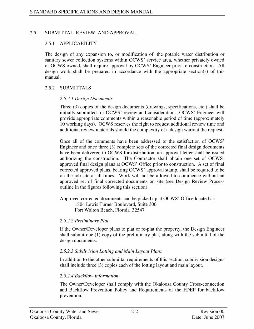
2.5 SUBMITTAL, REVIEW, AND APPROVAL
2.5.1 APPLICABILITY
The design of any expansion to, or modification of, the potable water distribution or sanitary sewer collection systems within OCWS’ service area, whether privately owned or OCWS-owned, shall require approval by OCWS’ Engineer prior to construction. All design work shall be prepared in accordance with the appropriate section(s) of this manual.
2.5.2 SUBMITTALS
2.5.2.1 Design Documents
Three (3) copies of the design documents (drawings, specifications, etc.) shall be initially submitted for OCWS’ review and consideration. OCWS’ Engineer will provide appropriate comments within a reasonable period of time (approximately 10 working days). OCWS reserves the right to request additional review time and additional review materials should the complexity of a design warrant the request. Once all of the comments have been addressed to the satisfaction of OCWS’ Engineer and once three (3) complete sets of the corrected final design documents have been delivered to OCWS for distribution, an approval letter shall be issued authorizing the construction. The Contractor shall obtain one set of OCWS-approved final design plans at OCWS’ Office prior to construction. A set of final corrected approved plans, bearing OCWS’ approval stamp, shall be required to be on the job site at all times. Work will not be allowed to commence without an approved set of final corrected documents on site (see Design Review Process outline in the figures following this section). Approved corrected documents can be picked up at OCWS’ Office located at:
1804 Lewis Turner Boulevard, Suite 300 Fort Walton Beach, Florida 32547
2.5.2.2 Preliminary Plat
If the Owner/Developer plans to plat or re-plat the property, the Design Engineer shall submit one (1) copy of the preliminary plat, along with the submittal of the design documents.
2.5.2.3 Subdivision Lotting and Main Layout Plans
In addition to the other submittal requirements of this section, subdivision designs shall include three (3) copies each of the lotting layout and main layout.
2.5.2.4 Backflow Information
The Owner/Developer shall comply with the Okaloosa County Cross-connection and Backflow Prevention Policy and Requirements of the FDEP for backflow prevention.

GENERAL INFORMATION
Okaloosa County Water and Sewer 2-3 Revision 00 Okaloosa County, Florida Date: June 2007
2.5.3 RESTRICTIONS
The Contractor shall not be allowed to begin construction on any potable water distribution or wastewater collection system without obtaining a set of OCWS-approved construction documents. Approval of the plans shall be valid for a period of 180 days. If construction has not begun by the end of the 180 days, the plans shall be declared void and a new submittal shall be required for approval. Any modifications to the plans shall be approved by all reviewing agencies.
2.6 NOTIFICATION OF CONSTRUCTION
The Developer’s Contractor shall pay all service connection costs and then notify OCWS’ Engineering Department two (2) weeks in advance of beginning the construction of any approved work to schedule a presconstruction meeting. Contractor shall notify OCWS’ engineering department 48 hours in advance of beginning the construction of any approved work for inspection services. OCWS’ Engineering Department will make periodic inspections of the proposed project while under construction. Once the water and sanitary sewer mains have been laid and successfully tested, OCWS will issue a preliminary approval letter permitting the street paving where applicable. A final letter of acceptance for the project will not be issued by OCWS until a successful field final inspection has been performed and all work is completed in accordance with these specifications. Call 609-5058 for inspections.
2.7 MAINTENANCE PERIOD
The Contractor Developer shall be responsible for the quality of all work installed for a period of not less than one (1) year after the final letter of acceptance has been issued.
2.8 RESPONSIBLE CHARGE OF CONSTRUCTION
The Developer/Owner is held to be in responsible charge of any job submitted to OCWS for construction. OCWS’ Engineering Personnel will make periodic inspection of the job site and will bring to the attention of the Contractor on the job, Engineer and the Developer any discrepancies that he may observe. This will in no way relieve the Developer, Engineer, or Contractor from their responsibility to comply with OCWS specifications.
2.9 DISPUTES, ERRORS, AND OMISSIONS
Should any portion of the plans and specifications be unclear or in dispute, they shall be brought to the attention of the individual(s) in responsible charge of construction. OCWS’ Engineering Department shall be notified as to the nature of the dispute and its proposed resolution prior to construction. It is the responsibility of the Developer/Owner to obtain approval from OCWS Engineering Department for any deviation from the original construction plans. Unless otherwise specified, OCWS’ Engineering Department will require revised plans to be submitted for approval. Construction on the disputed work shall not be allowed until the Developer obtains approval of the revised plans. Failure to obtain written approval could result in the rejection of the work and require the removal of all disputed portions of the installation at no cost to OCWS.

STANDARD SPECIFICATIONS AND DESIGN MANUAL
Okaloosa County Water and Sewer 2-4 Revision 00 Okaloosa County, Florida Date: June 2007
2.10 CHANGE OF CONDITIONS/MISREPRESENTATIONS/CHANGE IN THE WORK
Should the site conditions vary significantly from those shown on the approved set of plans or should the developer or owner modify the design, Okaloosa County and OCWS will require that the plans be corrected and resubmitted for approval. Resubmittal shall result in the stoppage of work pertaining to all of the changes in the design until such time as the plans have been reviewed and approved by Okaloosa County.
+++ END OF SECTION +++

OOKKAALLOOOOSSAA CCOOUUNNTTYY WWAATTEERR AANNDD SSEEWWEERR DDEEPPAARRTTMMEENNTT AAVVAAIILLAABBIILLIITTYY RREEVVIIEEWW PROCESS
CUSTOMER/DEVELOPER
SUBMITS SITE PLANS OR
DEVELOPER REVIEW PLANS (DRP) TO THE
DEPARTMENT OF GROWTH
MANAGEMENT (DOGM)
CUSTOMER/DEVELOPER REQUESTS OCWS
CUSTOMER SERVICE TO COMPLETE AN OCWS
WATER AND SEWER AVAILABITY REVIEW
FORM (WSARF) NO
IS SEWER SERVIC
E
DOES WATER
AND SEWER
REQUEST REQUIRE A
OCWS CUSTOMER
SERVICE SUBMITS WSARF
TO OCWS
ENGINEERING FOR REVIEW
NO
YES
CAN SEWER
SERVICE BE MADE
AVAILABLE BY OCWS?
NO
IS ONSITE SEWER
SERVICE AN
OPTION?
OCWS ENGINEERING COMPLETES
NON AVAILABITY LETTER
AND SUBMITS IT TO THE
COUNTY HEALTH DEPT.,
OCWS CUSTOMER SERVICE,
CUSTOMER, AND OCWS
ENGINEERING FILE
YES
CUSTOMER REQUESTS OCWS TO
SHARE WATER AND
SEWER
END OF PROCESS
YES
NO
OCWS MAINTENANCE AND CONSTRUCTION
PREPARES COST ESTIMATE TO
PROVIDE WATER/SEWER
AND PERFORMS A CONSTRUCTABILITY
REVIEW
CUSTOMER
AGREES TO COST SHARE
YES
NO
OCWS CUSTOMER SERVICE INITIATES
A WORK ORDER TO
YES
NO
OCWS AGREES TO COST SHARE WATER
YES
OCWS CUSTOMER SERVICE DIRECTS
DEVELOPER/CUSTOMER TO DOGM TO INITIATE A
DEVELOPMENTAL REVIEW
PLAN AND COMPLETE A CRF
CCOONNCCUURRRREENNCCYY RREEVVIIEEWW PPRROOCCEESSSS
NO
NO
IS WATER
SERVICE AVAILABLE?
NO
CAN WATER
SERVICE BE MADE
AVAILABLE
IS ONSITE WATER
SERVICE AN
OCWS ENGINEERING COMPLETES
NON AVAILABITY LETTER
AND SUBMITS IT TO THE
NWFWMD, OCWS CUSTOMER
SERVICE, CUSTOMER, AND OCWS
ENGINEERING FILE
YES
NO
YES
YES
YES
END OF PROCESS
CCOONNSSTTRRUUCCTTIIOONN//IINNSSPPEECCTTIIOONN PHASE
Figure 2-1
Revision 00 Date: June 2007

OOKKAALLOOOOSSAA CCOOUUNNTTYY WWAATTEERR AANNDD SSEEWWEERR DDEEPPAARRTTMMEENNTT CCOONNCCUURRRREENNCCYY RREEVVIIEEWW PPRROOCCEESSSS
CCOONNSSTTRRUUCCTTIIOONN//IINNSSPPEECCTTIIOONN PPHHAASSEE
CUSTOMER/DEVELOPER SUBMITS SITE PLANS OR
DEVELOPER REVIEW PLANS (DRP) TO THE
DEPARTMENT OF GROWTH
MANAGEMENT (DOGM)
DOGM SUBMITS THE DRP
AND CRF TO OCWS ENGINEERING
FOR REVIIEW
DOGM DIRECTS CUSTOMERTO
OCWS ENGINEERING
CUSTOMER SUBMITS CRF AND SITE
PLANS TO OCWS ENGINEERING
FOR REVIEW
IS CRF APPROVED?
NO
NO
NO
YES
YES
YES
OCWS ENGINEERING RETURNS CRF TO DOGM
AND COMPLETES A SERVICE CONNECTION
FORM (SCF) FOR CONSTRUCTION
SERVICES AND MAINTENANCE
OCWS ENGINEERING SUBMITS THE SCF
TO CUSTOMER SERVICE
AND MAINTENANCE
NO
YES
IS TRC
REVIEW REQUIRED ?
IS CRF APPROVED?
IS THE DRP
APPROVED BY OCWS
ENGINEERING
PLANS DENIED BY OCWS ENGINEERING OR RESUBMITTAL REQUIRED BY OTHER DEPARTMENTS AND NOTIFY ENGINEER OF
RECORD AND DOGM
PLANS APPROVED WITH NO EXCEPTIONS
PLANS APPROVED
AS NOTED OR WITH
MODIFICATIONS
DEVELOPER MODIFYS OR REVISES PLANS TO ADDRESS COMMENTS
AND RESUBMITS TO OCWS ENGINEERING
FOR REVIEW
APPROVED PLANS WITH COMMENTS,
RESUBMITTAL INFORMATION, AND
PERMITS ARE RETURNED
TO DEVELOPER OR ENGINEER OF RECORD
OCWS ENGINEERING REVIEWS THE RESUBMITTAL INFORMATION
NO YES
ARE THE DEVELOPMEN
TAL PLANS
APPROVED WITH NO
EXCEPTIONS?
OCWS ENGINEERING RETURNS CRF TO
DOGM AND COMPLETES SCF
AND SUBMITS IT TO CUSTOMER SERVICE AND MAINTENANCE
YES
NO
DEVELOPER
RESUBMITS THE DRP?
END OF PROCESS
WWAATTEERR AANNDD SSEEWWEERR AAVVAAIILLAABBIILLIITTYY RREEVVIIEEWW PPRROOCCEESSSS
IS THE DRP
APPROVED WITH NO
EXCEPTIONS
NO
YES
Revision 00 Date: June 2007 Figure 2-2
DEVELOPER RESUBMITS FINAL CONSTRUCTION
PLANS TO OCWS FOR SIGNATURE

OOKKAALLOOOOSSAA CCOOUUNNTTYY WWAATTEERR AANNDD SSEEWWEERR DDEEPPAARRTTMMEENNTT CCOONNSSTTRRUUCCTTIIOONN//IINNSSPPEECCTTIIOONN PROCESS
OCWS MAINTENANCE BEGINS CONSTRUCTION AND INSPECTION PHASE
OCWS MAINTENANCE COORDINATES WITH
DEVELOPER AND INSTALLS SERVICE
CONNECTION
CUSTOMER/DEVELOPER
EXECUTES DEVELOPER AGREEMENT WITH OCWS CUSTOMER
SERVICE AND PAYS SERVICE CONNECTION
FEES
OCWS MAINTENANCE AND CONSTRUCTION
HOLDS PRECONSTRUCTION CONFERENCE WITH
DEVELOPER AND ENGINEER
OCWS INSPECTION DEPARTMENT
INSPECTS DEVELOPER INSTALLED
INFRASTRUCTURE
NO
YES PROJEC
T PASSES
FINAL INSPECTION?
OCWS INSPECTION DEPARTMENT
PREPARES A PUNCH LIST OF
DEFECTS
DEVELOPER SUBMITS
FINAL APPROVAL CERTIFICATION
DOCUMENTS
NO
YES FINAL CERTIFICATION DOCUMENTS
DEVELOPER REVISES AND
RESUBMITS FINAL APPROVAL CERTIFICATION
DOCUMENTS
OCWS ENGINEERING PREPARES AND ISSUES
A LETTER FOR CAPACITY EXPANSION CHARGES (TAPS) AND SUBMITS
IT TO THE DEVELOPER, ENGINEER, OCWS
CUSTOMER SERVICE AND
CONSTRUCTION AND MAINTENANCE DEPT.
DEVELOPER PURCHASES CAPACITY
EXPANSION CHARGES (TAPS) AND OCWS
CUSTOMER SERVICE ISSUES WORK ORDER
TO OCWS CONSTRUCTION
AND MAINTENANCE DEPT.
TO INSTALL WATER METER
DEVELOPER APPLIES FOR BUILDING
PERMIT FROM DOGM.
CUSOMER SERVICE ISSUES WORKORDER
TO OCWS MAINTENANCE
AND CONSTRUCTION FOR SERVICE
CONNECTIONS
CCOONNCCUURRRREENNCCYY RREEVVIIEEWW PPRROOCCEESSSS
WWAATTEERR AANNDD SSEEWWEERR AAVVAAIILLAABBIILLIITTYY RREEVVIIEEWW PPRROOCCEESSSS
Revision 00 Date: June 2007 Figure 2-3
PRELIMINARY INSPECTIONS


SECTION 3
DRAFTING STANDARDS


OKALOOSA COUNTY WATER AND SEWER
SECTION 3 TABLE OF CONTENTS
Okaloosa County Water and Sewer Revision 00 Okaloosa County, Florida Date: June 2007
SECTION 3 DRAFTING STANDARDS 3.1 PURPOSE................................................................................................................1 3.2 DRAWING REQUIREMENTS .............................................................................1 3.2.1 Sheet Size.....................................................................................................1 3.2.2 Electronic Submittals ...................................................................................1 3.2.3 Title Block Information ...............................................................................1 3.2.4 Horizontal and Vertical Scales.....................................................................2 3.2.4.1 Plans and Profiles.............................................................................2 3.2.4.2 Plat ...................................................................................................2 3.2.5 Graphic Scale ...............................................................................................2 3.2.6 Shading ........................................................................................................2 3.2.7 Lettering.......................................................................................................2 3.2.8 Utility Locations ..........................................................................................2 3.3 DRAWING PACKAGE ..........................................................................................3 3.3.1 Title Sheet Requirements.............................................................................3 3.3.2 Plat/Lotting Layout ......................................................................................3 3.3.3 Plan and Profile Sheet Requirements...........................................................4 3.3.3.1 Plan View.........................................................................................4 3.3.3.2 Profile View.....................................................................................5 3.3.4 Detail Sheet ..................................................................................................6


OKALOOSA COUNTY WATER AND SEWER
SECTION 3 DRAFTING STANDARDS
Okaloosa County Water and Sewer 3-1 Revision 00 Okaloosa County, Florida Date: June 2007
3.1 PURPOSE
The intent of this section is to set forth a common format and information requirement for all construction related submittals. The following section presents the guidelines to which all construction plans shall adhere.
3.2 DRAWING REQUIREMENTS
For any connection, regardless of size, to Okaloosa County Water and Sewer’s (OCWS) water distribution or sanitary sewer collection systems, OCWS shall require construction plans to be submitted for review and approval. Construction shall not proceed until written approval by OCWS has been obtained.
3.2.1 SHEET SIZE
Full size construction plans shall be submitted on the preferred American National Standard sheet size of 22.00” X 34.00” (“D” size). OCWS may approve construction plans submitted on 11" X 17" on a case-by-case basis.
3.2.2 ELECTRONIC SUBMITTALS
All commercial projects and projects that involve more than two single family dwellings and that require TRC review shall be submitted in electronic form on a compact disk (CD) using the 2000 or later version of Auto CAD or Adobe Reader (pdf format).
3.2.3 TITLE BLOCK INFORMATION
In an effort to streamline project tracking and facilitate the review process, OCWS requires a title block (of the Design Engineer’s choosing) be located on each sheet of the drawing package. At a minimum, the title block shall contain the following information: • Engineering Firm’s Name, Address, and Telephone Number • Professional Engineer’s Seal/Signature and date of issuance • Project Title • Project Address (if available) • Drawing Title • CAD drawing file name, Engineer's Project Number, Design Engineer's Email
Address • Sheet Number (in “Sheet __ of __” Format) • Scale (indicate “NA” in block if not applicable)

STANDARD SPECIFICATIONS AND DESIGN MANUAL
Okaloosa County Water and Sewer 3-2 Revision 00 Okaloosa County, Florida Date: June 2007
3.2.4 HORIZONTAL AND VERTIICAL SCALES
3.2.4.1 Plans and Profiles
The appropriate scales for original plans are 1”= 50’ horizontal with vertical scale of 1”= 5’ and 1”= 20’ horizontal with vertical scale of 1”= 2’. For the purposes of clarity, other scales may be allowed with the approval of OCWS’ Engineer. Engineer shall use the appropriate scale to maximize the visual representation of the project. OCWS may require changes in scale or multiple scales to achieve their goal.
3.2.4.2 Plat
The appropriate scale for plat sheets shall vary to accommodate the project scope. It is recommended that the scale chosen by the Engineer be rounded to the nearest 100’ increment (i.e.; 1” = 100’, 1” = 200’, 1” = 500’, etc.).
3.2.5 GRAPHIC SCALE
A graphic scale shall be required on each sheet. The purpose of the graphic scale is to allow for the reduction of the plans while maintaining an accurate reference to scale.
3.2.6 SHADING
The use of shading to indicate areas of interest will not be allowed except that digital aerials will be allowed to be lightly shaded. Cross-hatching or dot patterns are acceptable techniques to highlight areas of interest. Shading is not permitting due in part to the difficulties in reproducing the documents for archival purposes. Shaded areas tend to produce either a dark block (obscuring items of interest) or no shading at all with the current reproducing process employed by OCWS.
3.2.7 LETTERING
Lettering shall be of a size and clarity that the document will remain legible when reduced 50%. Acceptable fonts include Roman-S for single stroke lettering and Roman - D for double stroke lettering, or similar. Drawings that are rendered illegible at 50% reduction shall be reformatted and resubmitted. Notes and title blocks shall not be adhesively applied on Drawings. All general notations shall be lettered in upper case; however, any lengthy sentence or phrase may be lettered in upper and lower case.
3.2.8 UTILITY LOCATIONS
The Engineer of Record shall utilize all existing utility locations in design considerations. Resolution of unforeseen utility conflicts during construction shall be the sole responsibility of the Engineer of Record.

DRAFTING STANDARDS
Okaloosa County Water and Sewer 3-3 Revision 00 Okaloosa County, Florida Date: June 2007
Engineer shall contact Sunshine State One-Call of Florida, Inc. at 800-432-4770 or 386-575-2009 to perform the required utility location survey during the design of the project and incorporate utility information into the design of the project.
3.3 DRAWING PACKAGE
In general, the drawing package shall consist of a Title Sheet, Plat Layout, Utility Plan, Drainage Plan, Profile Sheet(s), Detail Sheet(s), and shall address all requirements of the project including drainage utility plans and profiles.
3.3.1 TITLE SHEET REQUIREMENTS
The following information shall be supplied on the Title Sheet of the design documents submitted to OCWS for review: • Name of Project • Index of Drawings, Vicinity Map, Legend, Graphic Scale, and North Arrow • General notes applicable to the complete set of plans shall be shown on the Title
Sheet if space permits or the first sheet, if necessary • The following note shall be placed on the Title Sheet or other appropriate sheet near
the front of the plans: “CAUTION EXISTING UTILITIES: UNDERGROUND UTILITY INFORMATION SHOWN ON THESE DRAWINGS IS NOT GUARANTEED TO BE ACCURATE OR ALL INCLUSIVE. LOCATION, SIZE, AND MATERIAL TYPE WERE OBTAINED FROM AVAILABLE RECORDS SUPPLIED BY THE RESPECTIVE UTILITY COMPANY. SUNSHINE STATE ONE-CALL OF FLORIDA, INC. 386-575-2009 MUST BE NOTIFIED 48 HOURS PRIOR TO ANY EXCAVATION FOR VERIFICATION OF LOCATION.” The vicinity map should be appropriately sized to identify major and minor roadways with sufficient detail to allow driving to the project site. The location and boundaries of the site should be clearly defined.
3.3.2 PLAT/LOTTING LAYOUT
The Plat/Lotting layout shall include, but not be limited to, the following: • All existing property lines, including their corners • Bearing and distance of all proposed property lines • Proposed property corners • Lot numbers • Street names • Building offset dimensions • Location of all existing water and sewer laterals • Existing and proposed sanitary and water easements with notations • Existing and proposed utility easements • Bearing and distance to the nearest Section corner

STANDARD SPECIFICATIONS AND DESIGN MANUAL
Okaloosa County Water and Sewer 3-4 Revision 00 Okaloosa County, Florida Date: June 2007
• Coordinates • Right of way dimensions with curve data • Elevations of ditches, curbs, roadways, existing grade using the datum specified in
Section 5.
3.3.3 PLAN AND PROFILE SHEET REQUIREMENTS
All plan and profile sheets shall be provided with a revision block to identify the following: • Date of revision • Detailed explanation of changes made. Each revision shall be referenced to the
specific Drawing change using a unique note number and symbol.
3.3.3.1 Plan View
The plan view shall include, but not be limited to, the following: • Existing and proposed sewer utilities, size, direction of flow, manholes, sewer
laterals, and appurtenances. • Existing and proposed water utilities, size, valve locations, lateral locations
and appurtenances. • Existing and proposed topographic features within a 50 foot radius of the
construction. • All existing and known proposed gas, electric, telephone conduits, fiber optic
cables, and any other underground or overhead utilities within a 50 foot radius of the construction area.
• All existing pipes, culverts, conduits, and utilities of any nature crossing the proposed improvements, plotted and labeled.
• North Arrow and Graphic Scale. • Stations shall be shown above each 100-foot station on 50-scale and 20-scale
plans (i.e. 1+00, 2+00, etc.) and above each 500-foot station on 100-scale plans (i.e. 5+00, 10+00, etc.).
• Station direction shall be either south to north or west to east. • Plans covering more than one sheet shall be cross-referenced on each sheet to
identify the location of the adjacent profile or plan sheet. Match lines are acceptable in plan view with proper referencing station or adjacent sheet number.
• Centerlines of the installed water or sewer utility shall be referenced by dimensions to the easement boundary and/or associated property boundary.
• Bench marks shall be accurately plotted and labeled on the plan. • Street names, houses, fences, and drives shall be shown for a minimum of 50
feet beyond right-of-way or the fronts of the houses for lines located in the street or rights-of-way.
• Trees, steps, walks, and other topographic features shall be shown to the extent that they may be pertinent to the improvement location or construction.
• Existing property lines, lot lines, easements, and other boundary lines shall be shown a minimum of 75 feet beyond any proposed or existing right-of-way.

DRAFTING STANDARDS
Okaloosa County Water and Sewer 3-5 Revision 00 Okaloosa County, Florida Date: June 2007
In instances where additional information is required, the limit shall be extended.
• Existing ditches having a bottom width of 4 feet or less shall be indicated by drawing the centerline of the ditch. Ditches and channels having a bottom width greater than 4 feet shall be shown by Drawing each side of the ditch and noting its width.
• Street right-of-way widths shall be shown adjacent to and after the street name. For example: ROAD 50’ R/W (if uniform width). ROAD (R/W varies) - with dimension if the width is not uniform.
• The phrase, "DO NOT DISTURB," shall be used to indicate existing conditions or facilities, which are to remain in place during construction.
3.3.3.2 Profile View
The information to appear in the profile view shall include, but not be limited to, the following: • The grid shall be set up on a 1-inch square basis. The vertical scale for 50-
scale plans shall be 1” = 5’ and for 20-scale plans shall be 1” = 2’. • The limits, by station, shall be shown for all encasements, tunnels, and bored
segments. • The type of backfill used, when not identified in the general notes, shall be
placed directly above the profile grid with leader and arrow defining the limits of each type of backfield.
• The ASTM designation of pipe classification shall be shown below the pipe profile if different from the designation and classification shown in the General Notes, or Standard Specifications.
• The pipe material, size, and grade shall be indicated between all manholes. This information shall be parallel to and shown above smaller pipes; however, on pipes of sufficient diameter, this information should be placed inside the pipe. Grades shall be shown as a percent (i.e., 0.50%).
• Invert elevation shall be shown to the nearest hundredth of a foot and at the following locations: - All breaks in the grade - Breaks necessary for profile continuation onto another sheet - Center line of standard manholes with continuous grade - Conduits that are critical to the pipe gradient - Intersecting pipe - All locations necessary to substantiate the profile grade - Both pipe invert edges when there is a drop or slant inlet
• Proposed manhole rim elevation shall be shown to the nearest tenth (e.g. Rim El. 424.9+/-).
• The water surface elevations of ponding and/or 100 year flooding areas shall be shown.
• The flow line of all ditches deeper than one foot having impact on sewer depth or location shall be plotted and labeled.
• Existing/proposed ground profile.

STANDARD SPECIFICATIONS AND DESIGN MANUAL
Okaloosa County Water and Sewer 3-6 Revision 00 Okaloosa County, Florida Date: June 2007
• The finish floor elevation for the lowest point of a building to be drained via gravity flow to the sewer (i.e., basement) shall be shown on the plans. When an elevation cannot be obtained, the Engineer shall estimate an elevation and duly note this fact by using the word “ASSUMED” adjacent to the elevation.
• Drainage pipe and structures, swales, and ditches, where conflicts or crossings occur, drainage facilities should be shown.
• Any underground telephone conduit, water lines, gas lines, etc., shall be shown when crossing the proposed facility.
3.3.4 DETAIL SHEET
Standard Drawings are drawings prepared by Okaloosa County Water and Sewer and furnished to the Design Engineer to incorporate into the final construction Contract Documents. These Drawings illustrate typical items of work (e.g. hydrant installations, deadman layout, etc.) and their requirements. These Standard Drawings are typically presented on a Detail Sheet at the end of the set of drawings. It is not practical to expect a “Standard Detail” to be applicable for every situation that might arise. Therefore, for any proposed construction that is not covered in the “Standard Details,” Okaloosa County Water and Sewer shall request “Special Details.” The “Special Details” shall be produced by the Engineer and shall have sufficient detail to accurately depict the proposed construction. Junction chambers, special pipe bedding and railroad crossings are typical examples of items, which might require Special Details.
+++ END OF SECTION +++

SECTION 4
FINAL RECORD DRAWINGS/AS-BUILTS


OKALOOSA COUNTY WATER AND SEWER
SECTION 4 TABLE OF CONTENTS
Okaloosa County Water and Sewer Revision 00 Okaloosa County, Florida Date: June 2007
SECTION 4 FINAL RECORD DRAWINGS/AS-BUILTS
4.1 PURPOSE................................................................................................................1 4.2 GENERAL...............................................................................................................1
4.3 PROCESS ................................................................................................................1 4.4 FINAL RECORD DRAWINGS/AS-BUILT REQUIREMENTS...........................1 4.5 SURVEYS ...............................................................................................................2 4.6 CERTIFICATION ...................................................................................................2 4.7 AUDIT OF RECORD DRAWINGS .......................................................................3


OKALOOSA COUNTY WATER AND SEWER
SECTION 4 FINAL RECORD DRAWINGS/AS-BUILTS
Okaloosa County Water and Sewer 4-1 Revision 00 Okaloosa County, Florida Date: June 2007
4.1 PURPOSE
The intent of this section is to ensure that the Final Record Drawings/As-builts accurately depict the water and wastewater facilities as constructed.
4.2 GENERAL
A record of all deviations from Okaloosa County Water and Sewer (OCWS) approved construction drawings shall be made by the CONTRACTOR. Where “as constructed” information differs from the original proposed information, the Engineer shall mark a line through the proposed information and add the corrected information near the crossed out original data. Original data shall under no circumstances be erased from the original plans. Changes must be sufficiently dark to ensure a quality image. NO RED LINE markings will be accepted. Change identified on the Record Drawings shall be noted in the revision block and labeled as "As Constructed Changes" and further annotated as required in Section 3. The Engineer of Record or Florida Registered Surveyor shall stamp and sign ALL SHEETS verified and submitted for Final Record Drawings.
4.3 PROCESS
OCWS will notify the ENGINEER/CONTRACTOR that a particular project is ready for Final Record Drawings. The Engineer shall produce the Final Record Drawings and submit three copies of them to OCWS for review. OCWS’ Engineer will review the submittal and verify the deviations noted. NOTE: The review process is to ensure compliance with OCWS' general guidelines and requirements, is only cursory, and in no way releases the Engineer from the liability of, or the responsibility for, his design. It is the Design Engineer’s responsibility to accurately depict the facilities as constructed.
4.4 FINAL RECORD DRAWINGS/AS-BUILT REQUIREMENTS
At a minimum, Final Record Drawings/As-Builts submitted to OCWS for consideration shall consist of drawing sheets (22” X 34”) containing the following information: • Title Block (See Section 3 of this Manual) • North arrow • Graphic scale • Overall plan view of the project

STANDARD SPECIFICATIONS AND DESIGN MANUAL
Okaloosa County Water and Sewer 4-2 Revision 00 Okaloosa County, Florida Date: June 2007
• Manhole rim and invert elevations, elevations of buried valves, and fittings established by employing referenced datums (See Section 5 of this Manual)
• Pipe information (bearings and distances, depth of cover, percent slope and material type) • Lateral information (location measurements from upstream manholes, perpendicular distance
from the mainline, depth, and sizing of lateral, and measurements from property corners, lateral size, and material type)
• Casing information (Start and end points, thickness, size, material type, grade, length including beginning and endpoint, etc.)
• Property line and easement information (See Section 6 of this Manual) • X, Y, and Z coordinates in state plane coordinates, as outlined in Section 5 of this manual,
for all appurtenances installed including meters, manholes, fire hydrants, valves, etc. • Single electronic copy of the final Record Drawings shall be submitted on compact disks in
the latest version of AutoCAD (as outlined in Section 3).
Final acceptance will not be made until an approved set of record drawings is received by OCWS.
4.5 SURVEYS
All as-built surveys shall be performed in accordance with Section 5 (Surveying), and referenced to Okaloosa County GIS Horizontal and Vertical Datums. On-site project benchmarks shall be flagged during the survey. Manhole rim elevations shall be determined in reference to a marked or painted spot on the rims. Invert measurements shall be taken with a plumb rod whenever possible. Non-plumb rod measurements shall be corrected to reflect the actual vertical measurement. Horizontal positions of As-Built improvements, which vary from plan locations, shall be noted.
4.6 CERTIFICATION
The three sets of As-Builts submitted to OCWS shall be certified and bear the seal of an Engineer or Surveyor licensed in the State of Florida and shall contain the following statement:
“I, (Engineer’s Name) , A LICENSED ENGINEER OR SURVEYOR IN THE STATE OF FLORIDA, CERTIFY THAT THIS AS-BUILT PLAN(S) OF THE WATER AND/OR SANITARY SEWER MAIN INSTALLATION OF (Project Name) IS CONSTRUCTED IN COMPLIANCE WITH THE OKALOOSA COUNTY WATER AND SEWER DEPARTMENT SPECIFICATION AND IS TRUE AND CORRECT TO THE BEST OF MY KNOWLEDGE AND BELIEF.
LICENSE NO. (SEAL)

FINAL RECORD DRAWINGS/AS-BUILTS
Okaloosa County Water and Sewer 4-3 Revision 00 Okaloosa County, Florida Date: June 2007
All As-Built surveys, which include improvements within easements across private property, shall require additional certification by a Registered Land Surveyor stating that all improvements are located within the easements and that improvements and easements are located correctly as shown.
4.7 AUDIT OF RECORD DRAWINGS
OCWS reserves the right to randomly audit and confirm the accuracy of data submitted on Final Record Drawings through the use of a third party Land Surveyor. Any discrepancies revealed by the audit shall be resolved by the Engineer to the satisfaction of OCWS’ Engineer and the third party Land Surveyor at no expense to OCWS.
+++ END OF SECTION +++


SECTION 5
SURVEYING


OKALOOSA COUNTY WATER AND SEWER
SECTION 5 TABLE OF CONTENTS
Okaloosa County Water and Sewer Revision 00 Okaloosa County, Florida Date: June 2007
SECTION 5 SURVEYING 5.1 PURPOSE................................................................................................................1 5.2 GENERAL STANDARDS......................................................................................1
5.3 HORIZONTAL AND VERTICAL CONTROL .....................................................1
5.3.1 Datums .........................................................................................................1 5.3.2 Project Control Points ..................................................................................1 5.3.2.1 Project Control Point Location ................................................1 5.3.2.2 Project Control Marker ............................................................1 5.3.2.3 Horizontal Control Points ........................................................2 5.3.2.4 Vertical Control Points ............................................................2 5.4 HORIZONTAL AND VERTICAL ACCURACY ..................................................2 5.5 INFORMATION SHOWN ON THE PLANS.........................................................2 5.6 ADDITIONAL DATA AND INFORMATION......................................................3 5.6.1 Field Profiles................................................................................................3 5.6.2 Cross-Sections Topography and Planimetry................................................3 5.6.3 Utilities.........................................................................................................3 5.6.4 Highways and Railroads ..............................................................................3 5.6.5 Existing Rights-of-Way, Easements and Property Lines.............................3 5.6.6 Sanitary Service connection Survey ............................................................4


OKALOOSA COUNTY WATER AND SEWER
SECTION 5 SURVEYING
Okaloosa County Water and Sewer 5-1 Revision 00 Okaloosa County, Florida Date: June 2007
5.1 PURPOSE
This section describes the survey requirements for design, construction, and acceptance of water and wastewater system improvement project
5.2 GENERAL STANDARDS
Unless otherwise specified, all surveying activities, including the preparation of maps, plans, and other documents based on survey information, shall be performed in accordance with the “Minimum Technical Standards for Land Surveying in the State of Florida.” All data collected by the surveys shall be coordinated under the guidance and supervision of a Land Surveyor or Engineer registered in the State of Florida.
5.3 HORIZONTAL AND VERTICAL CONTROL
5.3.1 DATUMS
All projects submitted to Okaloosa County Water and Sewer (OCWS) for consideration shall be referenced to Okaloosa County Geographical Information Systems Horizontal and Vertical Datums. Horizontal datum shall be Florida State Plane Coordinate System, North Zone, NAD 83 – 90, Vertical datum shall be NAVD 1988. The source for horizontal and vertical datum shall be the established Okaloosa County GIS monuments. This information shall be obtained from the Okaloosa County GIS Department.
5.3.2 PROJECT CONTROL POINTS
5.3.2.1 Project Control Point Location
Project horizontal and vertical control points shall be established in the vicinity of the project using generally accepted survey methods. These new points shall be set within the public right-of-way or easement limits, be located so as to avoid disturbance, and generally provide coverages of the entire project area.
5.3.2.2 Project Control Marker
Project horizontal and vertical control points shall consist of semi-permanent markers or objects recoverable by conventional survey metal detectors or by location reference points.

STANDARD SPECIFICATIONS AND DESIGN MANUAL
Okaloosa County Water and Sewer 5-2 Revision 00 Okaloosa County, Florida Date: June 2007
Points set in the ground in maintained areas shall be flush with the ground. Trees are not to be used for setting control points or references except where there is no practical alternative. No spikes, nails, etc., are to driven into a tree, except under the above described circumstances. Trees shall not be “blazed” under any circumstances, and only water-based paint may be used if it is necessary to mark a tree. It shall be the responsibility of the Project Engineer or Surveyor to maintain the required horizontal and vertical control points until final acceptance.
5.3.2.3 Horizontal Control Points
Project horizontal control may be established directly on system features (such as manholes, valves, etc.), by APS observation, or by the use of traditional survey control points and/or baselines. A minimum of two inter-visible points shall be required to monument the horizontal datum.
5.3.2.4 Vertical Control Points
Project vertical control shall include a minimum of two points, one near each end of the project, or one point per 1000 feet ± for larger projects.
5.4 HORIZONTAL AND VERTICAL ACCURACY
New project horizontal control points shall be established with positional accuracies of 1:5000. New project vertical control points shall be established with level run closures of ± 0.005’ X (distance in miles)1/2 or the equivalent. Horizontal and vertical accuracies for alignment data (coordinates, bearings and distances, elevations, etc.) are the same as for control points. Horizontal locations of topographic and planimetric features shall be accurate to within ± 0.5 feet. Vertical locations of structures and map features shall be ± 0.01 ft for artificial features and ± 0.10 feet for natural features.
5.5 INFORMATION SHOWN ON THE PLANS
All horizontal, vertical, and other information critical to the design and construction of the improvements shall be shown on the plans. Such data and information shall include, but not be limited to the following: • Notes identifying the horizontal and vertical datums and monuments on which they are based
shall be shown on the plans and other applicable documents. References to other pertinent datums related to the project, such as previous survey, design, or construction datums, shall be identified by notes, including conversion factors relating to the datum.
• Locations, descriptions, coordinates and/or elevations of new project control points and associated reference points.
• Alignment data of the improvements, including coordinates, bearings and distances, elevations, final stations, offsets, and curve data.

SURVEYING
Okaloosa County Water and Sewer 5-3 Revision 00 Okaloosa County, Florida Date: June 2007
• Offset distances to parallel features (such as roads, railroads, ditches, sidewalks, R/Ws, easement limits, etc.) within 30 feet of the improvement alignment.
5.6 ADDITIONAL DATA AND INFORMATION
It may be necessary to obtain and provide additional data and information critical to the design and construction of the improvements. Such data and information may include, but not be limited to, that described in the following sections.
5.6.1 FIELD PROFILES
Profile elevations along the improvement alignment shall be obtained at approximately 50 - 100 ft intervals with intermediate grade breaks or sufficiently spaced to accurately depict the terrain. Profile drawings shall delineate all existing improvements, structures, roads, ditches, streams, etc., within 25 feet of the improvement alignment, with notes regarding size, type, and description of such feature.
5.6.2 CROSS-SECTIONS TOPOGRAPHY AND PLANIMETRY
Cross-sections or topography and planimetry may be necessary at critical locations to evaluate alignment, slope, and excavation requirements. All cross-sections, topography, and planimetry critical to the improvement design shall be shown on the plans or other documents. Topography generated from aerial photography shall be clearly identified as such, with notes regarding date of photography, original mapping scale and contour intervals, and datum references. The accuracy and completeness of this work is the sole responsibility of the Engineer or Land Surveyor even though obtained from other sources. Field checks and supplemental field topographic surveys may be required as necessary.
5.6.3 UTILITIES
Information regarding all publicly and privately owned surface and subsurface utilities affecting the proposed improvements shall be shown on the plans. This information shall be obtained by field surveys of existing utilities located by the Utility Owner and existing maps that may be supplied by the utilities.
5.6.4 HIGHWAYS AND RAILROADS
When portions of the improvements are within railroad or road right-of-ways, topography and planimetry shall be provided as necessary for the design and construction of the improvements or as required by the affected reviewing agency
5.6.5 EXISTING RIGHTS-OF-WAY, EASEMENTS, AND PROPERTY LINES
Where the location of the improvements in relation to the existing features such as rights-of-way, easements, and property lines is critical to the design or construction, sufficient information shall be shown to correctly establish the location of such features. Notes

STANDARD SPECIFICATIONS AND DESIGN MANUAL
Okaloosa County Water and Sewer 5-4 Revision 00 Okaloosa County, Florida Date: June 2007
regarding the source of such information, and the name and address of OCWS or owning agencies shall also be shown. Existing monumentation, pertinent improvements and evidences of prescriptive use within the project limits shall be shown. Where improvements are located within Florida Department of Transportation (DOT) right-of-ways, Engineer shall identify and reference on the drawings the specific DOT roadway name, stationing, and centerline offsets. Drawings shall show the station identification and offsets every 50 feet or more as needed.
5.6.6 SANITARY SERVICE CONNECTION SURVEY
Where existing housing is present along the site of a proposed sewer extension or replacement, a sanitary service connection survey shall be conducted. The survey shall determine the controlling elevations for design. The following information shall be shown. • Type of structure • Basement facilities (if present) • Size, type, and location of existing service lateral • Elevation of the lowest possible living area floor • Any additional information that may be required for design of the sewer line
All elevations should be determined by actual field measurements; however, if a unit cannot be entered, an estimated lowest living area floor elevation shall be made from a known elevation from some other point on the unit. In this case, the elevation must be clearly marked as being estimated. Should an estimated elevation control or have the potential to control the vertical elevation of the sewer, OCWS' Engineer shall arrange provisions for entry and actual determination of service elevation.
+++ END OF SECTION +++

SECTION 6
EASEMENTS


OKALOOSA COUNTY WATER AND SEWER
SECTION 6 TABLE OF CONTENTS
Okaloosa County Water and Sewer Revision 00 Okaloosa County, Florida Date: June 2007
SECTION 6 EASEMENTS
6.1 PURPOSE................................................................................................................1 6.2 GENERAL...............................................................................................................1
6.2.1 Acquisition...............................................................................................................1 6.2.2 Location .......................................................................................................1 6.2.3 Certification Criteria ....................................................................................1 6.2.4 Restrictions ..................................................................................................1 6.2.5 Schedule.......................................................................................................2 6.3 EASEMENT WIDTHS............................................................................................2 6.4 PLATTED EASEMENTS .......................................................................................3 6.5 DEEDED EASEMENTS BY DOCUMENT...........................................................3 6.5.1 Legal Description.........................................................................................3 6.5.2 Easement Location Sketch...........................................................................3 6.6 EASEMENT ENCROACHMENT..........................................................................4 6.7 PROPERTY SERVICE CONNECTION EASEMENT ..........................................4 6.8 FIELD VERIFICATION .........................................................................................4


OKALOOSA COUNTY WATER AND SEWER
SECTION 6 EASEMENTS
Okaloosa County Water and Sewer 6-1 Revision 00 Okaloosa County, Florida Date: June 2007
6.1 PURPOSE
The purpose of this section is to provide guidelines for developing easement documents required as part of a water or wastewater improvement project.
6.2 GENERAL
All proposed sanitary sewer or water distribution system improvements must be constructed in public rights-of-way, platted or deeded easements, or Okaloosa County Water and Sewer (OCWS) owned property.
6.2.1 ACQUISITION
Easements will generally be acquired by plat recorded utility easement, or by deed. In any case, it should be clear from the wording of the dedication or the description that the intent is to convey a utility easement rather than a fee parcel, and that the rights of the use include constructing, operating, maintaining, and accessing the facility or appurtenances.
6.2.2 LOCATION
Whenever possible, easements shall be strips of uniform width located along and parallel with existing boundary or easement property. Without running along a boundary, the easement should be located so as to minimize interference with other property rights. Easement widths and location shall be approved by OCWS prior to conveyance. It should also be clear as to the dimensions, length width, area, and location of the easement, as well as the specific use (water, sewer, general utilities) and whether the easement is permanent or temporary.
6.2.3 CERTIFICATION CRITERIA
All easement documents (plats or descriptions) not prepared by OCWS shall be prepared under the supervision of a Florida Registered Land Surveyor and shall be in accordance with “Minimum Technical Standards for Land Surveying in the State of Florida” and with Section 5 (Surveying) of this manual.
6.2.4 RESTRICTIONS
Proposed easements that are partially or wholly within existing easements shall not be accepted without the permission of the existing easement Owner.

STANDARD SPECIFICATIONS AND DESIGN MANUAL
Okaloosa County Water and Sewer 6-2 Revision 00 Okaloosa County, Florida Date: June 2007
No structures, either existing or proposed, shall be permitted within an easement without prior approval of OCWS. Easements shall not be vacated without a reversion clause in the original conveyance, or without an officially recorded act of abandonment by OCWS and the property Owner. Utility easements provided to serve multi-family dwellings, or a single family development that includes OCWS maintained water and sewer utilities shall stipulate in the recorded easement document that the Owner or the Developer shall be responsible for repair or restoration of pavement, sidewalks, landscaping, and drainage facilities.
6.2.5 SCHEDULE
Project schedules shall be established as to allow sufficient time for easement acquisition whether obtained by OCWS or the Developer. In the case of off site easements, approval for construction shall not be provided without the proper easements in place. Easement location and requirements shall be determined as early as possible.
6.3 EASEMENT WIDTHS
Whenever possible, the total easement width (permanent and temporary) should be sufficient to permit the Contractor to have flexibility in the method of construction. Minimum widths of Sanitary Sewer, Water Distribution, and Temporary Construction Easements using trench construction are tabulated below; however, in no case shall these guidelines be a substitute for sound engineering judgment.
Permanent Easement1 Temporary / Construction Easement1 SIZE OF
MAIN Water Distribution Sanitary Sewer Water Distribution/Sanitary
Sewer
4” - 6” 3 x depth of
pipe (15 ft. min.)
3 x depth of pipe (15 ft. min.)
8” - 12” 3 x depth of
pipe (15 ft. min.)
3 x depth of pipe (15 ft. min.)
15’ on each side of permanent easement
Other As required by OCWS
As required by OCWS As required by OCWS
1 Permanent and Temporary/Construction easement widths are subject to site conditions. Okaloosa County Water and Sewer reserves the right to request easement widths greater than the minimum illustrated in the table above if site conditions require.

EASEMENTS
Okaloosa County Water and Sewer 6-3 Revision 00 Okaloosa County, Florida Date: June 2007
6.4 PLATTED EASEMENTS
Plats shall clearly show easement widths, lengths, dimensions, areas, specific use, and location in relation to plat or lot boundary lines. A statement of dedication to OCWS shall be shown on the plat, and shall include any restrictions of use not otherwise shown.
6.5 DEEDED EASEMENTS BY DOCUMENT
Easements not obtained by platting shall be acquired by recorded utility easements or deeds. When acquired for OCWS by the Developer, OCWS shall be furnished with one original and one copy of the recorded documents. When the easements are to be acquired directly by OCWS, the Engineer shall provide OCWS with necessary owner information and shall submit a legal description and easement location sketch.
6.5.1 LEGAL DESCRIPTION
For easements not obtained by OCWS, a legal description shall be prepared by a Land Surveyor registered in the State of Florida. The legal description shall include pertinent information including but not limited to: • Project title • Creation date • Revisions dates • Name and address of grantor • Grantor’s tax parcel ID number • Recording information for parent parcel
6.5.2 EASEMENT LOCATION SKETCH
An easement location sketch shall be prepared on 8½ X 11” or 11” X 17” paper to accompany the legal description. The sketch shall include a project title, date, and revisions dates corresponding to the legal description. Also included are the following: • North arrow and graphic scale • Proposed easement widths, lengths, dimensions, areas, and locations in relation to
property lines. • Type of easement (permanent or temporary) • Specific use of easement (water, sewer, general utilities, etc.) • Parent parcel Owner’s name, address, tax parcel ID number, and recording
information (recorded utility easement or deed or plat book and page numbers) • Any existing or proposed structures within the easement • General location references to section, township and range, or recorded plats • Any existing easements or rights of way including owning agency, R/W widths, road
names, and source information • Easement location sketches should contain enough information to enable a Land
Surveyor to locate and stake the easement in the field.

STANDARD SPECIFICATIONS AND DESIGN MANUAL
Okaloosa County Water and Sewer 6-4 Revision 00 Okaloosa County, Florida Date: June 2007
6.6 EASEMENT ENCROACHMENT
On occasion, a permanent structure or landscaping is found to be encroaching upon an existing easement. In such cases, OCWS shall review each encroachment on a case-by case basis. If OCWS' Engineer deems it acceptable, the Owner shall prepare a drawing depicting the location and description of the encroachment. The Drawing shall be suitable for recording and meet the requirements of easement location sketches as outlined in this section. The Owner shall also complete the latest revision of the “Owner Information Sheet for Hold Harmless Agreement for Encroachment into OCWS Easement,” which may be obtained from OCWS.
6.7 PROPERTY SERVICE CONNECTION EASEMENT
Occasionally, a sanitary sewer may be located such that the permanent easement does not extend to the property line of an adjacent property to be served with a proposed property service connection. This occurs due to topographic or geographic considerations such as parallel streams. In these instances, a 10 foot sanitary sewer and water easement shall be provided from the proposed service facility easement to the property line at the most likely location of the property service connection. Sufficient temporary construction easement shall also be provided.
6.8 FIELD VERIFICATION
When required by OCWS, the Engineer shall field stake all existing utilities, existing and proposed easements, related property lines, and other pertinent structures to clearly establish location.
+++ END OF SECTION +++

SECTION 7
WATER DISTRIBUTION


OKALOOSA COUNTY WATER AND SEWER
SECTION 7 TABLE OF CONTENTS
Okaloosa County Water and Sewer Revision 00 Okaloosa County, Florida Date: June 2007
SECTION 7 WATER DISTRIBUTION SYSTEMS 7.1 PURPOSE................................................................................................................1 7.2 RECLAIMED/REUSE WATER PIPING SYSTEMS ............................................1 7.3 GENERAL LOCATION CRITERIA......................................................................1 7.3.1 Water Main Location ...................................................................................1 7.3.1.1 Installation in Right-of-Way....................................................1 7.3.1.2 Installation in Dedicated Easement..........................................2 7.3.1.3 Installation Along Lot Lines ...................................................2 7.3.2 Water Lateral Location ................................................................................2 7.3.3 Fire Hydrant Location..................................................................................2 7.3.4 Valve Location.............................................................................................3 7.3.4.1 Commercial and Residential Areas..........................................3 7.3.4.2 Cul-de-sac ................................................................................3 7.3.4.3 Dead End Street .......................................................................3 7.3.5 Meter and Vault/Meter Box Location..........................................................3 7.4 DESIGN CRITERIA ...............................................................................................3 7.4.1 Fire Flow Requirements...............................................................................4 7.4.2 Design Calculations .....................................................................................4 7.4.3 Pressure and Friction Loss ...........................................................................4 7.4.4 Diameter.......................................................................................................4 7.4.5 Allowable Deflection of Ductile-Iron Pipe Joints .......................................5 7.4.6 Flanged Pipe.................................................................................................5 7.4.7 Fire Hydrants ...............................................................................................5 7.4.7.1 General .....................................................................................5 7.4.7.2 Installation ...............................................................................6 7.4.7.3 Single-Family Residential........................................................6 7.4.7.4 Multi-Family Residential/Commercial ....................................6 7.4.7.5 Obstacle Clearance...................................................................6 7.4.8 Dead Ends ..................................................................................................6 7.4.9 Main Terminus Extensions ..........................................................................6 7.4.10 Separation of Water and Sewer Mains.........................................................7 7.4.10.1 Horizontal Separation ..............................................................7 7.4.10.2 Vertical Separation...................................................................7

WATER DISTRIBUTION SYSTEM
Okaloosa County Water and Sewer Revision 00 Okaloosa County, Florida Date: June 2007
7.4.11 Water Main/Sewer Crossing ........................................................................8 7.4.12 Water Main/Storm Water Crossing .............................................................8 7.4.13 Laterals.........................................................................................................8 7.4.14 Lateral Size and Maximum Number of Water Meters.................................8 7.4.15 Thrust Restraint............................................................................................8 7.4.15.1 Mechanically Restrained Pipe and Fittings..............................9 7.4.15.2 Thrust Blocks ...........................................................................9 7.4.16 Operation of Existing Water Distribution Facilities ....................................9 7.4.17 Trench Preparation.......................................................................................9 7.4.17.1 General .....................................................................................9 7.4.17.2 Excavation................................................................................9 7.4.17.3 Sheeting and Bracing .............................................................10 7.4.18 Dewatering ................................................................................................10 7.4.19 Pipe Line Construction ..............................................................................11 7.4.19.1 Pipe Laying ............................................................................11 7.4.19.2 Backfilling..............................................................................12 7.4.19.3 Valves and Fittings ................................................................12 7.4.20 Encasement Requirements .........................................................................12 7.4.20.1 General ...................................................................................12 7.4.20.2 Encasement Pipe ....................................................................12 7.4.20.3 Encasement Spacers...............................................................12 7.4.20.4 Encasement Ends ...................................................................13 7.4.21 Cross Connection Control..........................................................................13 7.5 MATERIAL REQUIREMENTS...........................................................................13 7.5.1 Inspection of Materials ..............................................................................13 7.5.2 Pipe ...........................................................................................................13 7.5.2.1 Ductile Iron Pipe ....................................................................13 7.5.2.2 Polyethylene Tubing ..............................................................14 7.5.2.3 PVC Pipe................................................................................14 7.5.2.4 HDPE Pipe .............................................................................14 7.5.3 Fittings .......................................................................................................14 7.5.3.1 Ductile Iron Pipe ....................................................................14 7.5.3.1.1 Mechanical Joint Fittings (4 through 12 inch)........14 7.5.3.1.2 Compact Fittings.....................................................14 7.5.3.1.3 Coatings ..................................................................15 7.5.3.1.4 Certificates ..............................................................15 7.5.3.2 Fittings (Less than 4 Inches) ..................................................15 7.5.4 Valves ........................................................................................................15 7.5.4.1 Resilient Wedge Gate Valves (4" -12") .................................15 7.5.4.2 Resilient Seat Gate Valves (2") .............................................16 7.5.5 Backflow Prevention Devices....................................................................16 7.5.6 Valve Boxes ...............................................................................................16 7.5.7 Tapping Sleeves .........................................................................................17 7.5.7.1 Restrainable Tapping Sleeves ................................................17 7.5.7.2 Non-Restrainable Tapping Sleeves........................................17 7.5.8 Tapping Valves ..........................................................................................17

STANDARD SPECIFICATIONS AND DESIGN MANUAL
Okaloosa County Water and Sewer Revision 00 Okaloosa County, Florida Date: June 2007
7.5.8.1 Tapping Valves (4" through 12")...........................................18 7.5.9 Encasements...............................................................................................18 7.5.9.1 Encasement Pipe ....................................................................18 7.5.9.2 Encasement Spacers...............................................................18 7.5.10 Fire Hydrants .............................................................................................19 7.5.10.1 Requirements .........................................................................19 7.5.10.2 Extensions ..............................................................................19 7.5.10.3 Coating/Painting ....................................................................19 7.5.11 Corporation Stops ......................................................................................19 7.5.11.1 Corporation Stops (¾" and 1")...............................................19 7.5.11.2 Corporation Stops (1½" and 2").............................................20 7.5.12 Service Saddle/Sleeve (¾" through 2".......................................................20 7.5.13 Grip Joint Coulp.........................................................................................20 7.5.14 Grip Pack Joint Coulp................................................................................21 7.5.15 Curb Stops ................................................................................................21 7.5.15.1 Curb Stops (¾" through 1") ...................................................21 7.5.15.2 Curb Stops (1½" through 2") .................................................21 7.5.16 Straight Pipe Couplings (¾" through 2") ...................................................21 7.5.17 Mechanical Restraint .................................................................................22 7.5.17.1 Wedge Action Restrainer Gland (for D.I. Pipe) ....................22 7.5.17.2 Wedge Action Restrainer for Push on Joints
(for D.I. Pipe).........................................................................22 7.5.17.3 Rubber Gasket Restraint for Push on Pipe (for
D.I. Pipe)................................................................................23 7.5.17.4 Rubber Gasket for Push on Pipe (for D.I. Pipe) ....................23 7.5.17.5 Pipe Bell Restraint Harness (for C900 D18 Pipe) ................23
7.5.17.6 Wedge Action Restrainer Gland (for PVC C900 DR18 Pipe) ..................................................................24
7.5.18 All Thread Rods and Eye Bolts .................................................................24 7.5.19 Backfill ................................................................................................24 7.5.19.1 Coarse Aggregate...................................................................24 7.5.19.2 Fine Aggregate.......................................................................25

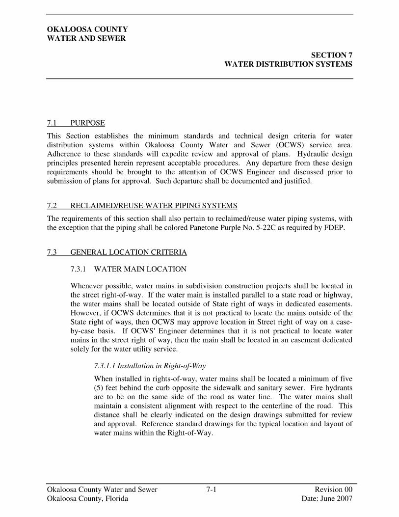
OKALOOSA COUNTY WATER AND SEWER
SECTION 7 WATER DISTRIBUTION SYSTEMS
Okaloosa County Water and Sewer 7-1 Revision 00 Okaloosa County, Florida Date: June 2007
7.1 PURPOSE
This Section establishes the minimum standards and technical design criteria for water distribution systems within Okaloosa County Water and Sewer (OCWS) service area. Adherence to these standards will expedite review and approval of plans. Hydraulic design principles presented herein represent acceptable procedures. Any departure from these design requirements should be brought to the attention of OCWS Engineer and discussed prior to submission of plans for approval. Such departure shall be documented and justified.
7.2 RECLAIMED/REUSE WATER PIPING SYSTEMS
The requirements of this section shall also pertain to reclaimed/reuse water piping systems, with the exception that the piping shall be colored Panetone Purple No. 5-22C as required by FDEP.
7.3 GENERAL LOCATION CRITERIA
7.3.1 WATER MAIN LOCATION
Whenever possible, water mains in subdivision construction projects shall be located in the street right-of-way. If the water main is installed parallel to a state road or highway, the water mains shall be located outside of State right of ways in dedicated easements. However, if OCWS determines that it is not practical to locate the mains outside of the State right of ways, then OCWS may approve location in Street right of way on a case-by-case basis. If OCWS' Engineer determines that it is not practical to locate water mains in the street right of way, then the main shall be located in an easement dedicated solely for the water utility service.
7.3.1.1 Installation in Right-of-Way
When installed in rights-of-way, water mains shall be located a minimum of five (5) feet behind the curb opposite the sidewalk and sanitary sewer. Fire hydrants are to be on the same side of the road as water line. The water mains shall maintain a consistent alignment with respect to the centerline of the road. This distance shall be clearly indicated on the design drawings submitted for review and approval. Reference standard drawings for the typical location and layout of water mains within the Right-of-Way.
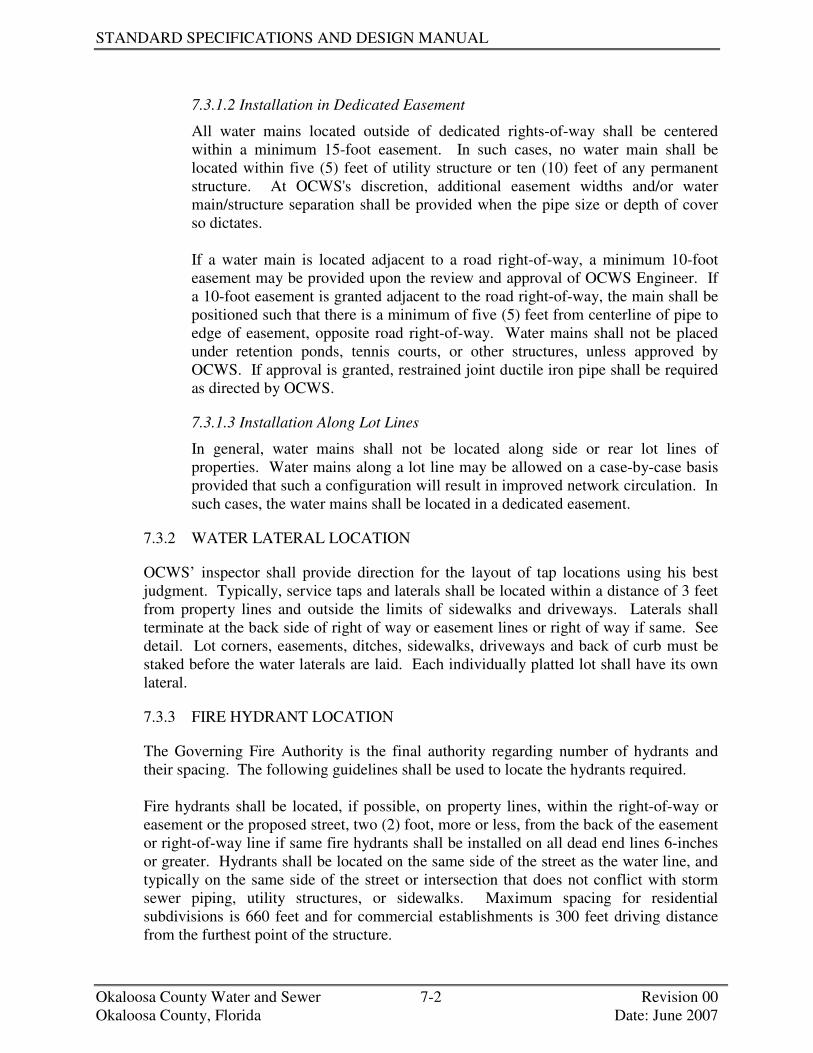
STANDARD SPECIFICATIONS AND DESIGN MANUAL
Okaloosa County Water and Sewer 7-2 Revision 00 Okaloosa County, Florida Date: June 2007
7.3.1.2 Installation in Dedicated Easement
All water mains located outside of dedicated rights-of-way shall be centered within a minimum 15-foot easement. In such cases, no water main shall be located within five (5) feet of utility structure or ten (10) feet of any permanent structure. At OCWS's discretion, additional easement widths and/or water main/structure separation shall be provided when the pipe size or depth of cover so dictates. If a water main is located adjacent to a road right-of-way, a minimum 10-foot easement may be provided upon the review and approval of OCWS Engineer. If a 10-foot easement is granted adjacent to the road right-of-way, the main shall be positioned such that there is a minimum of five (5) feet from centerline of pipe to edge of easement, opposite road right-of-way. Water mains shall not be placed under retention ponds, tennis courts, or other structures, unless approved by OCWS. If approval is granted, restrained joint ductile iron pipe shall be required as directed by OCWS.
7.3.1.3 Installation Along Lot Lines
In general, water mains shall not be located along side or rear lot lines of properties. Water mains along a lot line may be allowed on a case-by-case basis provided that such a configuration will result in improved network circulation. In such cases, the water mains shall be located in a dedicated easement.
7.3.2 WATER LATERAL LOCATION
OCWS’ inspector shall provide direction for the layout of tap locations using his best judgment. Typically, service taps and laterals shall be located within a distance of 3 feet from property lines and outside the limits of sidewalks and driveways. Laterals shall terminate at the back side of right of way or easement lines or right of way if same. See detail. Lot corners, easements, ditches, sidewalks, driveways and back of curb must be staked before the water laterals are laid. Each individually platted lot shall have its own lateral.
7.3.3 FIRE HYDRANT LOCATION
The Governing Fire Authority is the final authority regarding number of hydrants and their spacing. The following guidelines shall be used to locate the hydrants required. Fire hydrants shall be located, if possible, on property lines, within the right-of-way or easement or the proposed street, two (2) foot, more or less, from the back of the easement or right-of-way line if same fire hydrants shall be installed on all dead end lines 6-inches or greater. Hydrants shall be located on the same side of the street as the water line, and typically on the same side of the street or intersection that does not conflict with storm sewer piping, utility structures, or sidewalks. Maximum spacing for residential subdivisions is 660 feet and for commercial establishments is 300 feet driving distance from the furthest point of the structure.

WATER DISTRIBUTION SYSTEM
Okaloosa County Water and Sewer 7-3 Revision 00 Okaloosa County, Florida Date: June 2007
Hydrants shall be placed at lot lines or in general to minimize potential conflict with future building plans.
7.3.4 VALVE LOCATION
Valves shall generally be located on property lines and/or right-of-way lines and at the radius points of intersections. In general, valves shall be located behind the back of curbs or edge of pavement.
7.3.4.1 Commercial and Residential Areas
Sufficient valves shall be provided on water mains so that inconvenience and sanitary hazards can be limited during repairs. Valves shall be located at every intersection of a grid and at not more than 800-foot intervals. As a general rule, valves 8 inches and less, shall be spaced along a main a minimum distance in feet of main diameter in inches times 100 (i.e., a 6 inch main would need a valve every 600 feet).
7.3.4.2 Cul-de-sac
Isolation valves are required at the intersection of the beginning of a cul-de-sac.
7.3.4.3 Dead End Street
Valves shall be required at the end of each dead end street or road, which could be extended in the future. The valve at a dead end shall be properly restrained joint pipe in order to allow future extension without disruption of service. Thrust blocks or rodding are not acceptable. No taps or service laterals will be allowed between said valve and plug (this will prevent service disruptions when the main is extended).
7.3.5 METER AND VAULT/METER BOX LOCATION
Meters shall be centered in the vault or meter box to allow for reading and ease of removal or maintenance. Large meters, 3 inches and greater, shall be installed at a location acceptable to OCWS and adjacent to the property boundary. At a minimum, a space of 10 feet by 16 feet of graded site shall be provided to locate the meter and box. The site shall be located outside the limits of any drainage facilities or parking lots, and in a well drained accessible location.
7.4 DESIGN CRITERIA
Water distribution systems shall be designed to satisfy the ultimate tributary population’s domestic/commercial water demand and fire protection requirements for the ultimate population to be served by the proposed line.

STANDARD SPECIFICATIONS AND DESIGN MANUAL
Okaloosa County Water and Sewer 7-4 Revision 00 Okaloosa County, Florida Date: June 2007
7.4.1 FIRE FLOW REQUIREMENTS
It is the responsibility of the Developer’s Engineer to coordinate with the local authorities having jurisdiction to ensure that fire flow requirements are met.
7.4.2 DESIGN CALCULATIONS
If requested by OCWS, the Developer’s Engineer shall submit signed, sealed, and dated design calculations along with the construction plans for the water distribution projects. Calculations shall show the water mains having sufficient hydraulic capacity to transport peak hourly flows and the combination of maximum daily fire flows while meeting the requirements of this section. Designed daily flow velocities shall not exceed 5 feet per second. Peak hour maximum daily flow velocities shall not exceed 10 feet per second anywhere in OCWS’ system.
7.4.3 PRESSURE AND FRICTION LOSS
All water mains shall be designed in accordance with this Section. The system shall be designed to maintain a minimum pressure of 20 psi at all points in the distribution system under all conditions of flow. Higher pressures may be required at commercial, industrial and high-density residential areas. Design Engineer is responsible for monitoring and measuring the normal working pressure at the point of connection of the new water line. Monitoring shall be performed for a minimum of 24-hours. Contact OCWS to coordinate location of connection to the system. For pressures greater than 75 psi, the Design Engineer may need to make special provisions (e.g. pressure reducing valves).
Friction losses through water mains shall be based on the Hazen and Williams formula. In the use of Hazen and Williams formula, the value for "C" shall be 120 for ductile iron pipe and 130 for PVC pipe. "C" values greater than 130 shall not be allowed.
7.4.4 DIAMETER
Only 4”, 6”, 8”, 10”, and 12” diameter water mains shall be permitted (larger sizes shall be considered on case-by-case basis). Four (4) inch water mains shall be permitted only in dead end or cul-de-sac areas with a maximum length of 300 feet of pipe. As a minimum, six (6) inch diameter gridded or looped systems shall be required in low-density residential projects. In commercial, industrial, and high-density residential areas, eight (8) inch minimum gridded or looped mains shall be required. Larger size mains shall be required to allow the withdrawal of the required fire flow while maintaining the residual pressure specified. Fire protection water mains shall be installed as follows: No fire main servicing a fire hydrant (public or private) shall be less than six (6) inches in diameter.
For systems containing mains less than eight (8) inches in diameter, OCWS may require the Design Engineer to submit a complete hydraulic analysis of the system. This submittal does not relieve the Design Engineer of responsibility for his design. He shall

WATER DISTRIBUTION SYSTEM
Okaloosa County Water and Sewer 7-5 Revision 00 Okaloosa County, Florida Date: June 2007
be responsible for ensuring that all elements thereof that supply water to hydrants and/or building fire protection systems can supply the required fire flow without exceeding the prescribed velocity.
7.4.5 ALLOWABLE DEFLECTION OF PVC C-900 and DUCTILE-IRON PIPE JOINTS
The maximum allowable deflection for ductile iron pipe shall be as given in AWWA C600. If the alignment requires deflection in excess of the above limitations, bends shall be furnished to provide angular deflections within the limit set forth. Joining of PVC pipe should be in accordance with ASTM D2321
Typical Maximum Deflections for PVC C-900 and Ductile Iron Pipe
Maximum Recommended Deflection Size Inches
Nominal Laying Length
Feet PVC- C-900
DIP Deflection Angle
4 20 3.5 3 6 20 3.5 3 8 20 3.5 3
10 20 3.5 3 12 20 3.5 3
7.4.6 FLANGED PIPE
Flanged pipe shall only be installed above ground or with the flanges in valve pits. Bolts shall be 316 stainless steel. Gaskets shall be Toruseal or equal.
7.4.7 FIRE HYDRANTS
7.4.7.1 General
This section provides the minimum requirements with regard to spacing. The local authority having jurisdiction may establish more stringent requirements regarding placement and interval of spacing. All fire hydrants shall be located as shown on the plans. The hydrants shall be located in such manner as to provide complete accessibility and also in a manner that the possibility of damage from vehicles or injury to pedestrians will be minimized. All hydrants shall stand plum with the pumper nozzle facing the curb and the bury line of the hydrant at the finished grade. Fire hydrants installed in state highway right-of-ways shall be in accordance with any Department of Transportation requirements. All fire hydrants shall be connected to the main in the manner shown in the Water Standard Detail Sheet. Also, where present, the retaining chains and swivel clips for the fire hydrant port caps must turn freely. The chains must be untangled and the swivel serving the cap must operate without hindrance.
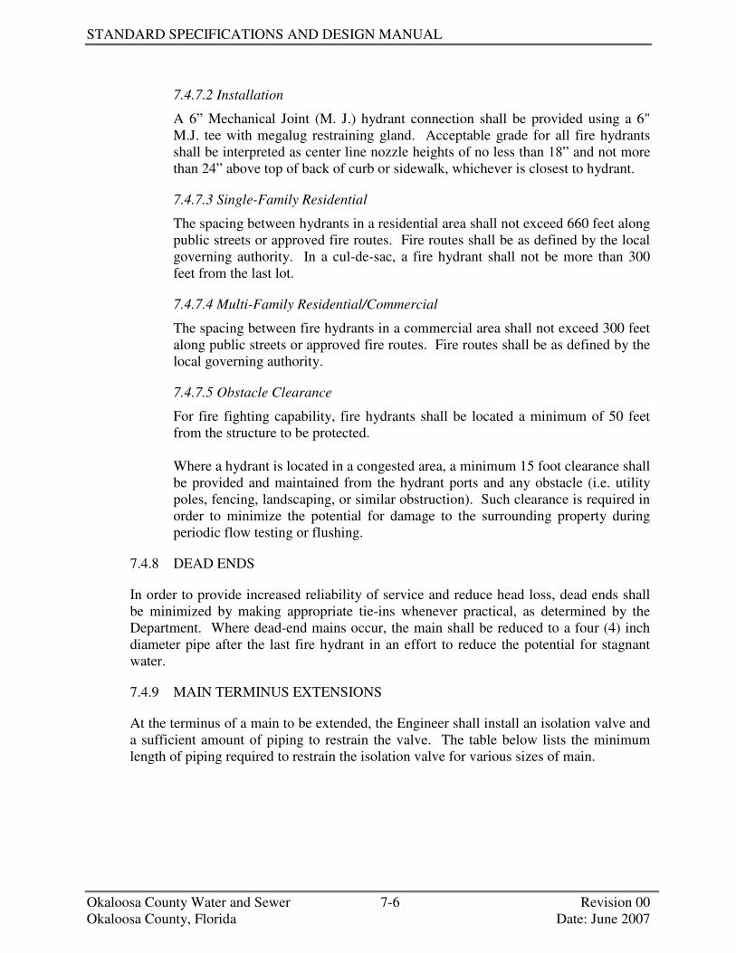
STANDARD SPECIFICATIONS AND DESIGN MANUAL
Okaloosa County Water and Sewer 7-6 Revision 00 Okaloosa County, Florida Date: June 2007
7.4.7.2 Installation
A 6” Mechanical Joint (M. J.) hydrant connection shall be provided using a 6" M.J. tee with megalug restraining gland. Acceptable grade for all fire hydrants shall be interpreted as center line nozzle heights of no less than 18” and not more than 24” above top of back of curb or sidewalk, whichever is closest to hydrant.
7.4.7.3 Single-Family Residential
The spacing between hydrants in a residential area shall not exceed 660 feet along public streets or approved fire routes. Fire routes shall be as defined by the local governing authority. In a cul-de-sac, a fire hydrant shall not be more than 300 feet from the last lot.
7.4.7.4 Multi-Family Residential/Commercial
The spacing between fire hydrants in a commercial area shall not exceed 300 feet along public streets or approved fire routes. Fire routes shall be as defined by the local governing authority.
7.4.7.5 Obstacle Clearance
For fire fighting capability, fire hydrants shall be located a minimum of 50 feet from the structure to be protected. Where a hydrant is located in a congested area, a minimum 15 foot clearance shall be provided and maintained from the hydrant ports and any obstacle (i.e. utility poles, fencing, landscaping, or similar obstruction). Such clearance is required in order to minimize the potential for damage to the surrounding property during periodic flow testing or flushing.
7.4.8 DEAD ENDS
In order to provide increased reliability of service and reduce head loss, dead ends shall be minimized by making appropriate tie-ins whenever practical, as determined by the Department. Where dead-end mains occur, the main shall be reduced to a four (4) inch diameter pipe after the last fire hydrant in an effort to reduce the potential for stagnant water.
7.4.9 MAIN TERMINUS EXTENSIONS
At the terminus of a main to be extended, the Engineer shall install an isolation valve and a sufficient amount of piping to restrain the valve. The table below lists the minimum length of piping required to restrain the isolation valve for various sizes of main.

WATER DISTRIBUTION SYSTEM
Okaloosa County Water and Sewer 7-7 Revision 00 Okaloosa County, Florida Date: June 2007
SIZE OF PIPE MINIMUM LENGTH OF PIPING REQUIRED TO RESTRAIN ISOLATION VALVE
4” - 6” 1 JOINT OF PIPING (APPROXIMATELY 20 FT.) 8” - 12” 2 JOINTS OF PIPING (APPROXIMATELY 40 FT.)
>12” AS DIRECTED BY THE OCWS ENGINEER
7.4.10 SEPARATION OF WATER AND SEWER MAINS
Water mains that are laid in the vicinity of existing or proposed pipelines designated to carry treated or untreated wastewater shall meet the horizontal and vertical separations as follows. Extreme care should be exercised when designing water mains at or near certain sites such as sewage treatment plants or industrial complexes. No water pipe shall pass through or come in contact with any part of a sanitary sewer manhole.
7.4.10.1 Horizontal Separation
NORMAL CONDITIONS: Water mains shall be located at least 10 feet horizontally from gravity and/or force mains carrying treated or untreated wastewater or current DEP Standard. The distance shall be measured from inside edge of pipe to inside edge of pipe. UNUSUAL CONDITIONS: When local conditions prevent a horizontal separation of 10 feet, a water main may be laid closer to a pipe carrying treated or untreated wastewater provided that the bottom of the water main is at least 18 inches above the top of the pipe carrying treated or untreated wastewater and the water main is laid in a separate trench or on an undisturbed earth shelf or current DEP Standard.
7.4.10.2 Vertical Separation
NORMAL CONDITIONS: Water mains shall be laid to provide a separation of at least 18 inches between the bottom of the water main and the top of the sewer or current DEP Standard. UNUSUAL CONDITIONS: When construction conditions at crossings prevent a vertical separation of 18 inches as described herein above, the sewer pipe shall be constructed of ductile iron pipe centered a minimum of 10 feet in both directions from point of crossing or current DEP Standard. The pipe joints on bottom shall be constructed to maximize spacing from crossings. Should it become necessary for the sewer to cross over the water main, special precautions will be required. Such cases shall require review and written approval by County.

STANDARD SPECIFICATIONS AND DESIGN MANUAL
Okaloosa County Water and Sewer 7-8 Revision 00 Okaloosa County, Florida Date: June 2007
7.4.11 WATER MAIN/ SEWER CROSSING
Ductile iron pipe shall be used at all line crossings. The ductile iron pipe shall extend 10 feet on either side of the crossing and shall maximize joint spacing. Whenever possible, water mains shall cross above sewer mains unless the previously described upgrades are enacted. Adequate structural support for both the water main and the sewer mains shall be provided to prevent excessive deflection of joints and settling. Ten (10) foot horizontal separation of water mains and storm drains is required, otherwise upgrade water main as previously specified until separation is regained.
7.4.12 WATER MAIN/STORM WATER CROSSING
Ductile iron pipe shall be used at all line crossings. The ductile iron pipe shall extend 10 feet on either side of the crossing and shall maximize joint spacing. Whenever possible, water mains are allowed to cross over drainage pipes as long as minimum 36” of cover from top of pipe to the finish grade (i.e., top of back of curb) and a minimum separation of 12 inches below the pipes is maintained. Where it is not possible to lay the water line go over the top of drainage pipes and maintain the required cover, the water main can be laid under drainage pipe by utilizing ductile iron mechanically restrained offset fittings. No water main shall pass through or come in contact with a storm drain pipe or manhole. A minimum separation of 12 inches or greater as prescribed by governing authority, shall be maintained between the water line and the drainage pipe. The minimum cover for the water line shall be 36 inches.
7.4.13 WATER SERVICE
With the exception of cul-de-sacs, water service shall, if at all possible, run perpendicular to the water main. Each individually platted lot shall have its own lateral.
7.4.14 WATER SERVICE SIZE AND MAXIMUM NUMBER OF WATER METERS
The maximum number of meters for 3/4 inch and 1 inch laterals is presented in the table below.
MAXIMUM NUMBER METERS SERVED LATERAL PIPE SIZE (INCHES) ¾” METERS (or) 1” METERS
¾ 1 N/A 1 2 1
7.4.15 THRUST RESTRAINT
Plugs, caps, tees and vertical or horizontal bends, on water lines 4 inches in diameter or larger, and fire/flush hydrants shall be provided with thrust restraints. Valves shall be securely anchored or shall be provided with thrust restraints to prevent movement.
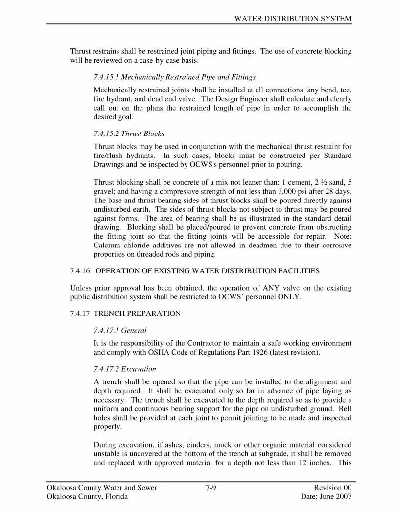
WATER DISTRIBUTION SYSTEM
Okaloosa County Water and Sewer 7-9 Revision 00 Okaloosa County, Florida Date: June 2007
Thrust restrains shall be restrained joint piping and fittings. The use of concrete blocking will be reviewed on a case-by-case basis.
7.4.15.1 Mechanically Restrained Pipe and Fittings
Mechanically restrained joints shall be installed at all connections, any bend, tee, fire hydrant, and dead end valve. The Design Engineer shall calculate and clearly call out on the plans the restrained length of pipe in order to accomplish the desired goal.
7.4.15.2 Thrust Blocks
Thrust blocks may be used in conjunction with the mechanical thrust restraint for fire/flush hydrants. In such cases, blocks must be constructed per Standard Drawings and be inspected by OCWS's personnel prior to pouring. Thrust blocking shall be concrete of a mix not leaner than: 1 cement, 2 ½ sand, 5 gravel; and having a compressive strength of not less than 3,000 psi after 28 days. The base and thrust bearing sides of thrust blocks shall be poured directly against undisturbed earth. The sides of thrust blocks not subject to thrust may be poured against forms. The area of bearing shall be as illustrated in the standard detail drawing. Blocking shall be placed/poured to prevent concrete from obstructing the fitting joint so that the fitting joints will be accessible for repair. Note: Calcium chloride additives are not allowed in deadmen due to their corrosive properties on threaded rods and piping.
7.4.16 OPERATION OF EXISTING WATER DISTRIBUTION FACILITIES
Unless prior approval has been obtained, the operation of ANY valve on the existing public distribution system shall be restricted to OCWS’ personnel ONLY.
7.4.17 TRENCH PREPARATION
7.4.17.1 General
It is the responsibility of the Contractor to maintain a safe working environment and comply with OSHA Code of Regulations Part 1926 (latest revision).
7.4.17.2 Excavation
A trench shall be opened so that the pipe can be installed to the alignment and depth required. It shall be evacuated only so far in advance of pipe laying as necessary. The trench shall be excavated to the depth required so as to provide a uniform and continuous bearing support for the pipe on undisturbed ground. Bell holes shall be provided at each joint to permit jointing to be made and inspected properly. During excavation, if ashes, cinders, muck or other organic material considered unstable is uncovered at the bottom of the trench at subgrade, it shall be removed and replaced with approved material for a depth not less than 12 inches. This

STANDARD SPECIFICATIONS AND DESIGN MANUAL
Okaloosa County Water and Sewer 7-10 Revision 00 Okaloosa County, Florida Date: June 2007
material shall be tamped in layers of 6 inches to provide a uniform and continuous bearing characteristic of that area’s soil condition. Where the bottom of the trench at subgrade consists of unstable material to such a degree that it cannot be removed and replaced with an approved material to support the pipe properly, a suitable foundation shall be constructed. Excavated material shall be piled in such manner that it will not endanger work, obstruct natural watercourse, sidewalks or driveways.
Fire hydrants and valve boxes or other utility controls shall be left unobstructed and accessible at all times. Street gutters shall be kept clear or other satisfactory provisions made for street drainage. All surface material, which is suitable for reuse in restoring the surface, shall be kept separate from the excavated materials.
7.4.17.3 Sheeting and Bracing
Open cut trenches shall be sheeted and braced as required by OSHA Code of Regulations Part 1926 (latest revision) and as may be necessary to protect life, property, or the work. Trench bracing may be removed after the backfilling has been completed or has been brought up to such an elevation as to permit its safe removal. a trenching box may e used in place of sheeting and bracing as long as said box is in compliance with above referenced OSHA Code.
7.4.18 DEWATERING
Water shall not be allowed in the trench at any time. An adequate supply of well points, headers, and pumps, all in first class operating condition, shall be used to remove the ground water. The use of gravel (angular stone/57 stone) and pumps shall also be an acceptable means of removing the water on a case-by-case basis as approved by the Department. At no time shall any pumps emit an unacceptable noise level that exceeds the County's ordinance, or the Contractor will be required to shut down pumping operations. The trench shall be excavated no more than the available pumping facilities are capable of handling. The discharge from pumps shall be routed to settling basins or other acceptable erosion and sedimentation control devices prior to discharging to natural or existing drainage channels or storm sewers. Any and all permits required for dewatering are the responsibility of the Contractor and shall be obtained prior to commencement of construction. The Department reserves the right to require the submittal of a dewatering plan in instances where complexity of the project dictates. When requested, the plan shall be designed and stamped by a Licensed Engineer registered in the State of Florida.

WATER DISTRIBUTION SYSTEM
Okaloosa County Water and Sewer 7-11 Revision 00 Okaloosa County, Florida Date: June 2007
7.4.19 PIPE LINE CONSTRUCTION
7.4.19.1 Pipe Laying
All water mains, service lines and appurtenances shall be installed as specified in these technical provisions and in accordance with the approved plans and appropriate standard detail sheets as provided herein.
The bottom of the trench shall not be excavated below the specified grade. If undercutting occurs, the bottom of the trench shall be brought up to the original grade with approved material, thoroughly compacted as directed by OCWS Engineer and/or his representative. Before placing pipe into the trench, the outside of the spigot and the inside of the bell shall be wiped clean and dry before applying lubrication. Every precaution shall be taken to prevent foreign material from entering the pipe. During laying operations, no debris, tools, clothing or other material shall be placed in the pipe. All mechanical joints shall be made up in strict accordance with the manufacturer’s specifications. Gaskets shall be evenly seated, the gland placed in position with the bolts, and evenly tightened. All slip joints shall be made up in strict accordance with the manufacturer’s specifications. The bell shall be carefully cleaned and lubricated before the gasket is inserted. After placing a length of pipe in the trench, the spigot end shall be centered in the bell, the pipe forced home, and brought to correct alignment per the manufacturer's recommended installation procedures. Water mains will be installed with 36” minimum cover. Maximum cover of 42” will be accepted. Cover depths will be determined from top of pipe to the top of finished landscaping grade as indicated on the plans. Exceptions to stated depth requirement include those portions of water main within casings or those portions that go over or under storm drains, sanitary sewers or other utilities as shown on plans. In those cases where depth differences are extreme or other circumstances prevent the use of offset fittings, properly restrained M. J. 45° bends can be used in conjunction with ductile iron pipe. Alignment and depth of pipe will e spot checked during construction and/or “As-Built” inspections. At times when pipe laying is not in progress, the open ends of the pipe shall be closed by a watertight plug or other approved means. This provision shall apply during the noon hour as well as overnight. If water is in the trench, the seal shall remain in place until the trench is pumped completely dry.

STANDARD SPECIFICATIONS AND DESIGN MANUAL
Okaloosa County Water and Sewer 7-12 Revision 00 Okaloosa County, Florida Date: June 2007
7.4.19.2 Backfilling
All backfilling material shall be free from cinders, ashes, refuse, vegetable or organic material, boulders, rocks, stones or other material which is considered unsuitable. Materials that are considered unsuitable must be disposed of off site in compliance with all pertinent codes of City State, County, and Federal regulatory agencies. The Contractor shall not backfill any fitting, thrust block restrainer gland, valve, hydrant assembly and/or meter/backflow assembly until such appurtenances have been inspected in place by a designated representative of OCWS or unless approved by OCWS. All such inspections shall be scheduled two (2) working days in advance.
7.4.19.3 Valves and Fittings
All valves and fittings shall be set and joined to the pipe in the proper location as specified in the plans. A roadway valve box shall be provided for every valve. This valve box shall not transmit shock or stress to the valve and shall be centered and plumb over the wrench nut of the valve. The box cover should be flush with surface of the finished pavement or grade level as specified in the plans. A bronze or stainless steel 2” diameter disc shall be cast into the pad for all valves 12” or larger. Valve nomenclature to be stamped into the disc shall include the valve manufacturer/model, the year produced, the valve size, type, number of turns, and direction to open the valve. The Design Engineer shall clearly label the requirement for this marker on the approved construction plans.
7.4.20 ENCASEMENT REQUIREMENTS
7.4.20.1 General
Encasement is required when crossing all railroads, and some State, County and City roadways, which have excessive traffic flow or other critical situations (such as protecting building foundations). Whenever possible, encasement and mains shall cross the roadway and/or railroad, perpendicular to the roadbed. A valve will be required on each end of the encasement. In all cases, the agency requiring the encasement shall have the final approval of the engineering design.
7.4.20.2 Encasement Pipe
Pipe to be installed under pavement where open trenching is not permitted shall be installed through steel casing, which has been jacked and bored. Casing shall extend beyond the back of slope or edge of pavement a minimum of 6 feet, whichever is greater.
7.4.20.3 Encasement Spacers
Water mains shall be pushed or pulled through the encasement piping on spacers placed no more than 10 feet apart. A minimum of two spacers/runners per joint of pipe shall be required. The spacer shall have a clearance range of 1 to 1.5 inches between the spacer and the inside of the encasement piping. Spacers shall be

WATER DISTRIBUTION SYSTEM
Okaloosa County Water and Sewer 7-13 Revision 00 Okaloosa County, Florida Date: June 2007
required in the first foot of each end of the encasement (See Miscellaneous Detail 120).
7.4.20.4 Encasement Ends
All casing ends shall be sealed with an engineered end sealing device.
7.4.21 CROSS CONNECTION CONTROL
The water purveyor (OCWS) shall require all privately maintained water systems, at their expense, to install an approved backflow prevention assembly. The selection, location, and installation of the device shall be based on OCWS’ “Cross-Connection and Backflow Prevention Policy” (latest revision), which may be obtained from OCWS.
7.5 MATERIAL REQUIREMENTS
7.5.1 INSPECTION OF MATERIALS
All materials delivered to the job site will be new and of domestic origin. All materials are subject to inspection by the Department’s representative. Any materials found during inspection or during the progress of the work to be defective or not meeting specifications shall be rejected and removed from the job site without delay. Materials and/or work not inspected by OCWS' representative prior to installation may be required by OCWS to be uncovered by the Contractor at his expense in order to verify compliance. Copies of the Packing Lists shall be furnished on demand.
7.5.2 PIPE
7.5.2.1 Ductile Iron Pipe
Ductile iron pipe shall be in accordance with ANSI A21.50/AWWA C150 and conform to requirements of A21.5/AWWA C 151. Push-on and restrained joint pipe shall have a minimum rated working pressure of 350 psi. All buried pipe shall be pressure class as follows:
SIZE (INCHES) PRESSURE CLASS
4 − 12 Class 350 >12 As Directed by Engineer
Pipe wall thickness shall be as specified in above referenced AWWA latest edition. Restrained joint ductile iron pipe shall be required for thrust restraints or for other situations that the Department deems necessary. All ductile iron pipe shall be cement-lined and seal-coated in accordance with ANSI/AWWA Standard C104/A21.4. All ductile iron pipe for underground installation shall be coated on the outside with a 1-mil thick bituminous material applied as recommended by the pipe manufacturer.

STANDARD SPECIFICATIONS AND DESIGN MANUAL
Okaloosa County Water and Sewer 7-14 Revision 00 Okaloosa County, Florida Date: June 2007
7.5.2.2 Polyethylene Tubing
Polyethylene tubing (DR 9) and fittings ¾” through 2”. All polyethylene tubing and fittings furnished shall conform to all applicable provisions and requirements of the latest revision of AWWA C901, C906, or CSA B137.1 and, by inclusion all appropriate standards referenced there in. In addition, the polyethylene tubing and fittings shall meet the requirements of NSF/ANSI Standard 14.
7.5.2.3 PVC Pipe
PVC pipe shall be in accordance with AWWA C-900 DR 18.
SIZE (INCHES) PRESSURE CLASS
4 − 12 Class 150 >12 As Directed by Engineer
7.5.2.4 HDPE Pipe
HDPE pipe shall conform to ASTM D 1248, PE 3408, Type III, Class C, Category 5 and Grade 34. The HDPE pipe shall be DR 11 with the Blue Striping @ 120 DEGREES. All connections to PVC shall be made using an MJ Adapter followed by a minimum of two DI pipe segments (restrained).
SIZE (INCHES) PRESSURE RATING
4 − 12 160 psi @ 73 F >12 As Directed by Engineer
7.5.3 FITTINGS
7.5.3.1 Ductile Iron Fittings
7.5.3.1.1 Mechanical Joint Fittings (4 through 12 inch)
All fittings shall be ductile iron mechanical joint for use with previously specified ductile-iron pipe. Cast ductile-iron fittings 4-inch through 12-inch shall be pressure rated at 350 psi minimum. All fittings shall conform to ANSI/AWWA C110/A21.10 and/or ANSI/AWWA C153/A21.53 (latest editions). All fittings shall be cast and machined allowing the bolt holes to straddle the vertical centerline. Only those fittings and accessories that are of domestic manufacture will be acceptable. All fittings shall be complete with gaskets, follower glands, alloy steel tee bolts and hex nuts.
7.5.3.1.2 Compact Fittings
Compact fittings will be allowed on 4” through 12” sizes only. All other sizes (larger than 12”) shall be full bodied.
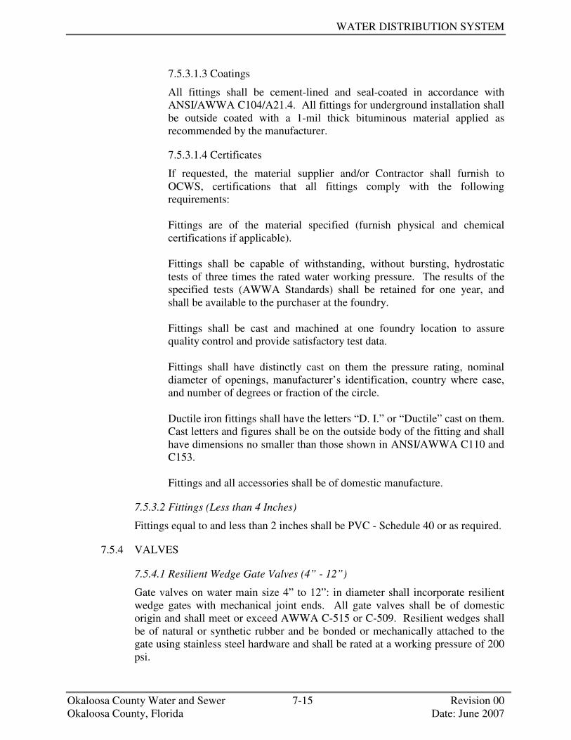
WATER DISTRIBUTION SYSTEM
Okaloosa County Water and Sewer 7-15 Revision 00 Okaloosa County, Florida Date: June 2007
7.5.3.1.3 Coatings
All fittings shall be cement-lined and seal-coated in accordance with ANSI/AWWA C104/A21.4. All fittings for underground installation shall be outside coated with a 1-mil thick bituminous material applied as recommended by the manufacturer.
7.5.3.1.4 Certificates
If requested, the material supplier and/or Contractor shall furnish to OCWS, certifications that all fittings comply with the following requirements: Fittings are of the material specified (furnish physical and chemical certifications if applicable). Fittings shall be capable of withstanding, without bursting, hydrostatic tests of three times the rated water working pressure. The results of the specified tests (AWWA Standards) shall be retained for one year, and shall be available to the purchaser at the foundry. Fittings shall be cast and machined at one foundry location to assure quality control and provide satisfactory test data. Fittings shall have distinctly cast on them the pressure rating, nominal diameter of openings, manufacturer’s identification, country where case, and number of degrees or fraction of the circle. Ductile iron fittings shall have the letters “D. I.” or “Ductile” cast on them. Cast letters and figures shall be on the outside body of the fitting and shall have dimensions no smaller than those shown in ANSI/AWWA C110 and C153. Fittings and all accessories shall be of domestic manufacture.
7.5.3.2 Fittings (Less than 4 Inches)
Fittings equal to and less than 2 inches shall be PVC - Schedule 40 or as required.
7.5.4 VALVES
7.5.4.1 Resilient Wedge Gate Valves (4” - 12”)
Gate valves on water main size 4” to 12”: in diameter shall incorporate resilient wedge gates with mechanical joint ends. All gate valves shall be of domestic origin and shall meet or exceed AWWA C-515 or C-509. Resilient wedges shall be of natural or synthetic rubber and be bonded or mechanically attached to the gate using stainless steel hardware and shall be rated at a working pressure of 200 psi.

STANDARD SPECIFICATIONS AND DESIGN MANUAL
Okaloosa County Water and Sewer 7-16 Revision 00 Okaloosa County, Florida Date: June 2007
The interior and exterior of the valve body shall be fusion-bonded epoxy coated in accordance with AWWA C-550 (latest edition) in order to provide a corrosion resistant seat, applied in a manner to withstand the action of line fluids and operation of the sealing gate under long-term service. Valve seats shall seal by compression only. Valves shall be supplied with 2” square operating nuts and shall be designed to provide a bubble or bottle tight seal regardless of direction of flow. Opening shall be in the counterclockwise direction. The following resilient wedge gate valves are accepted for installation:
MANUFACTURER MODEL NO.
American Flow Control Series 2500 Mueller A-2360
7.5.4.2 Resilient Seat Gate Valves (2”)
All 2” gate valves located below grade must be ductile iron resilient wedge meeting or exceeding AWWA C515 standards, latest edition. All 2” gate valves shall have a standard 2” operating nut and standard FPT openings. No bronze/brass type gate valves will be accepted in underground applications.
MANUFACTURER SIZE MODEL NO.
American Flow Control 2” 502 Mueller 2” A-2360
7.5.5 BACKFLOW PREVENTION DEVICES
The Owner/Developer shall comply with the Okaloosa County Cross-connection and Backflow Prevention Policy and Requirements of the FDEP for backflow prevention.
7.5.6 VALVE BOXES
Cast iron valve boxes shall be provided for all vales installed underground. The valve boxes shall be adjustable to fit the depth of earth covered over the valve and shall be designed so as to prevent the transmission of surface loads directly to the valve or piping. The valve boxes shall be manufactured of cast iron and shall be of the two piece design, screw type, including a bottom section and top section with lid cover. Only those valve boxes that are of domestic manufacture will be acceptable. The casting shall be manufactured of clean, even grain, gray cast iron with a minimum tensile strength of 21,000 psi. It shall be smooth, true to pattern, free from blowholes, sand holes, projections and other harmful defects. The seating surface of both the lid cover and the top section shall be cast so that the cover will not rock after it has been
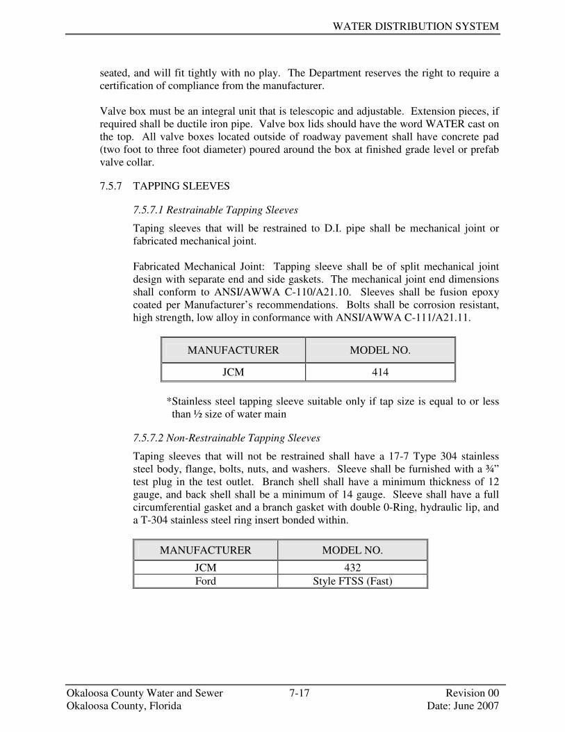
WATER DISTRIBUTION SYSTEM
Okaloosa County Water and Sewer 7-17 Revision 00 Okaloosa County, Florida Date: June 2007
seated, and will fit tightly with no play. The Department reserves the right to require a certification of compliance from the manufacturer. Valve box must be an integral unit that is telescopic and adjustable. Extension pieces, if required shall be ductile iron pipe. Valve box lids should have the word WATER cast on the top. All valve boxes located outside of roadway pavement shall have concrete pad (two foot to three foot diameter) poured around the box at finished grade level or prefab valve collar.
7.5.7 TAPPING SLEEVES
7.5.7.1 Restrainable Tapping Sleeves
Taping sleeves that will be restrained to D.I. pipe shall be mechanical joint or fabricated mechanical joint. Fabricated Mechanical Joint: Tapping sleeve shall be of split mechanical joint design with separate end and side gaskets. The mechanical joint end dimensions shall conform to ANSI/AWWA C-110/A21.10. Sleeves shall be fusion epoxy coated per Manufacturer’s recommendations. Bolts shall be corrosion resistant, high strength, low alloy in conformance with ANSI/AWWA C-111/A21.11.
MANUFACTURER MODEL NO.
JCM 414 *Stainless steel tapping sleeve suitable only if tap size is equal to or less
than ½ size of water main
7.5.7.2 Non-Restrainable Tapping Sleeves
Taping sleeves that will not be restrained shall have a 17-7 Type 304 stainless steel body, flange, bolts, nuts, and washers. Sleeve shall be furnished with a ¾” test plug in the test outlet. Branch shell shall have a minimum thickness of 12 gauge, and back shell shall be a minimum of 14 gauge. Sleeve shall have a full circumferential gasket and a branch gasket with double 0-Ring, hydraulic lip, and a T-304 stainless steel ring insert bonded within.
MANUFACTURER MODEL NO.
JCM 432 Ford Style FTSS (Fast)

STANDARD SPECIFICATIONS AND DESIGN MANUAL
Okaloosa County Water and Sewer 7-18 Revision 00 Okaloosa County, Florida Date: June 2007
7.5.8 TAPPING VALVES
7.5.8.1 Tapping Valves (4” through 12”)
Tapping valves for 4” - 12” taps shall be ductile iron resilient seating meeting AWWA C509 with a minimum working pressure of 200 psi. Valves shall be full port opening to accept full-size shell cutters and shall be provided with an alignment ring. Valves shall be non Rising Stem (NRS) with a 2” square nut. The following tapping valves are approved for use.
MANUFACTURER MODEL NO.
American Flow Control 2500 Mueller T-2360
7.5.9 ENCASEMENTS
7.5.9.1 Encasement Pipe
Where water main borings are required, the encasement pipe shall conform to the requirements of ASTM A53, Grade B steel piping (for sizes 24” and smaller). The encasement shall be set straight and true to grade as indicated on the construction plans. Each end shall be sealed. Thicknesses listed herein are minimum requirements. Borings under railroads or State highways shall meet their respective permit requirements.
Encasement size and thickness shall be as indicated below:
DIAMETER OF WATER MAIN
(INCHES)
MINIMUM CASING
DIAMETER (INCHES)
MINIMUM CASING
THICKNESS (INCHES)
ASTM / AWWA STANDARD
4 12 .25 ASTM A53 6 14 .25 ASTM A53 8 16 0.375 ASTM A53
10 18 0.375 ASTM A53 12 24 0.375 ASTM A53
7.5.9.2 Encasement Spacers
Encasement spacers shall be as manufactured by Cascade Water Works, Inc., Advanced Products and Systems, Inc., or Pipeline Seal and Insulator, Inc. Spacers for 4” - 12” piping shall be stainless steel with 8” long runners as shown on the applicable details.
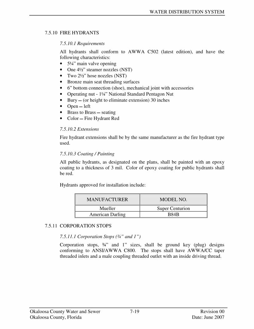
WATER DISTRIBUTION SYSTEM
Okaloosa County Water and Sewer 7-19 Revision 00 Okaloosa County, Florida Date: June 2007
7.5.10 FIRE HYDRANTS
7.5.10.1 Requirements
All hydrants shall conform to AWWA C502 (latest edition), and have the following characteristics: • 5¼” main valve opening • One 4½” steamer nozzles (NST) • Two 2½” hose nozzles (NST) • Bronze main seat threading surfaces • 6” bottom connection (shoe), mechanical joint with accessories • Operating nut - 1¼” National Standard Pentagon Nut • Bury � (or height to eliminate extension) 30 inches • Open � left • Brass to Brass � seating • Color � Fire Hydrant Red
7.5.10.2 Extensions
Fire hydrant extensions shall be by the same manufacturer as the fire hydrant type used.
7.5.10.3 Coating / Painting
All public hydrants, as designated on the plans, shall be painted with an epoxy coating to a thickness of 3 mil. Color of epoxy coating for public hydrants shall be red. Hydrants approved for installation include:
MANUFACTURER MODEL NO.
Mueller Super Centurion American Darling B84B
7.5.11 CORPORATION STOPS
7.5.11.1 Corporation Stops (¾” and 1”)
Corporation stops, ¾” and 1” sizes, shall be ground key (plug) designs conforming to ANSI/AWWA C800. The stops shall have AWWA/CC taper threaded inlets and a male coupling threaded outlet with an inside driving thread.

STANDARD SPECIFICATIONS AND DESIGN MANUAL
Okaloosa County Water and Sewer 7-20 Revision 00 Okaloosa County, Florida Date: June 2007
The following devices have been accepted for installation:
MANUFACTURER MODEL NO.
Ford FB 1000-3-G Ford FB 1000-4-G
7.5.11.2 Corporation Stops (1½” and 2”)
Corporation Stops, 1½” and 2” sizes. shall be ball corporation designs conforming to ANSI/AWWA C800. The stops shall have AWWA/CC taper threaded inlets and a female iron pipe thread outlet. Corporation stops, sizes 1½” and 2”, shall be tapped onto mains through the use of an approved service saddle. The following devices have been accepted for installation:
DESCRIPTION
MANUFACTURER CATALOG NO. VALVE INLET OUTLET
Ford FB 1600-7 2” 2” 2” Mueller B-20045 2” 2” 2”
7.5.12 SERVICE SADDLE/SLEEVE (¾” THROUGH 2”)
In an effort to eliminate problems with direct taps, such a stripped or leaking threads and split pipe, all ¾” through 2” taps shall be made through the use of approved service saddles/sleeves. The service saddle/sleeve will have a body with an AWWA/CC threaded outlet, seal, and suitable means for attachment to the main meeting the requirements of ANSI/AWWA C800. The service/saddle/sleeve shall be designed to provide a drip tight connection when used as a service connection to the main. Service saddles shall be double strapped, heavy-duty design, with a corrosion resistant finish for up to a 12” main.
The following service saddles/sleeves have been accepted for installation on ductile iron water main: • ¾” – 2” Service Saddles/Sleeves
MAIN SIZE SADDLE/SLEEVE
Less than or equal to 12” Ford 202B, JCM 406 Greater than 12” As Directed by Engineer

WATER DISTRIBUTION SYSTEM
Okaloosa County Water and Sewer 7-21 Revision 00 Okaloosa County, Florida Date: June 2007
7.5.13 GRIP JOINT COUPLING
DESCRIPTION MANUFACTURER CATALOG
NO. CORP SIZE INLET OUTLET Ford C84-33G ¾” Mip CTS Ford C84-44G 1” Mip CTS Ford C84-66G 1½” Mip CTS Ford C84-77G 2” Mip CTS
7.5.14 GRIP PACK JOINT COUPLING
DESCRIPTION MANUFACTURER CATALOG
NO. CORP SIZE INLET OUTLET Ford C14-33G ¾” Fip CTS Ford C14-44G 1” Fip CTS Ford C14-66G 1½” Fip CTS Ford C14-77G 2” Fip CTS
7.5.15 CURB STOPS
7.5.15.1 Curb Stops (¾” through 1”)
DESCRIPTION MANUFACTURER CATALOG
NO. CURB SIZE INLET OUTLET Ford B43-232WG 5/8” 3/4” 5/8” X 3/4” Ford B13-232W 5/8” ¾” 5/8” Ford B41-233WG 5/8” ¾” ¾” Ford B41-344WG ¾” 1” 1” Ford B43-344WG ¾” 1” 1” Ford B11-333W ¾” ¾” ¾”
Mueller B-20283 ¾” ¾” ¾” Ford B11-444W 1” 1” 1”
Mueller B-0283 1” 1” 1”
7.5.15.2 Curb Stops (1½" through 2")
Curb stops for services shall be bronze ball valves.
DESCRIPTION MANUFACTURER CATALOG
NO. TYPE SIZE OUTLET
Ford BF43-666WG Ball Valve 1½” Meter Flange Ford BF43-777WG Ball Valve 2” Meter Flange Ford B41-777WG Ball Valve 2” Female IP Ford B11-777W Ball Valve 2” Female IP

STANDARD SPECIFICATIONS AND DESIGN MANUAL
Okaloosa County Water and Sewer 7-22 Revision 00 Okaloosa County, Florida Date: June 2007
7.5.16 STRAIGHT PIPE COUPLINGS (¾” THROUGH 2”)
DESCRIPTION MANUFACTURER CATALOG
NO. TYPE SIZE OUTLET Ford C44-33-G Compression ¾” ¾” Ford L44-33G Compression ¾” ¾”
Mueller H-15403 Compression ¾” ¾” Ford C44-44-G Compression 1” 1” Ford L44-44G Compression 1” 1”
Mueller H-15403 Compression 1” 1” Ford C44-66-G Compression 1½” 1½” Ford L44-66G Compression 1 ½” 1 ½”
Mueller H-15403 Compression 1½” 1½” Ford C44-66-G Compression 2” 2” Ford L44-77G Compression 2” 2”
Mueller H-15403 Compression 2” 2”
7.5.17 MECHANICAL RESTRAINT
7.5.17.1 Wedge Action Restrainer Gland (for D. I. Pipe)
Restraint for standardized mechanical joint fittings shall be incorporated in the design of the follower gland and shall impart multiple wedging action against the pipe, increasing its resistance as the pressure increases. Restraining glands shall be manufactured of high strength ductile iron conforming to ASTM A536. The wedges shall be ductile iron and heat treated to a minimum hardness of 370 BHN. Dimensions of the gland shall be such that it can be used with the standardized mechanical joint bell conforming to ANSI/AWWA C111/A21.11 and ANSI/AWWA C153/A21.53.
EBAA IRON “MEGALUG” SERIES 1100
FORD “UNI-FLANGE” SERIES 1400 NOMINAL
PIPE SIZE SERIES
NUMBER
NUMBER OF
WEDGES
CATALOG NUMBER
NUMBER OF
WEDGES
RATED PRESSURE
4” 1104 2 UFR 1400-D-4 2 350 6” 1106 3 UFR 1400-D-6 3 350 8” 1107 4 UFR 1400-D-8 4 350
10” 1110 6 UFR 1400-D-10 6 350 12” 1112 8 UFR 1400-D-12 8 350
7.5.17.2 Wedge Action Restrainer for Push-on Joints (for D. I. Pipe)
Restraint for push-on bells of ductile iron pipe shall consist of a wedge action retainer gland installed on the pipe spigot, connected to a ductile iron follower

WATER DISTRIBUTION SYSTEM
Okaloosa County Water and Sewer 7-23 Revision 00 Okaloosa County, Florida Date: June 2007
gland installed behind the pipe bell. The connecting rods and nuts shall be of high strength, low alloy material meeting ANSI/AWWA C111/A21.11. The wedge action retainer assembly for push-on pipe shall be in a kit form from a single manufacturer.

STANDARD SPECIFICATIONS AND DESIGN MANUAL
Okaloosa County Water and Sewer 7-24 Revision 00 Okaloosa County, Florida Date: June 2007
EBAA IRON “MEGALUG” SERIES 1700
FORD “UNI-FLANGE” SERIES 1450
NOMINAL PIPE SIZE SERIES
NO. #OF TIE BOLTS
TIE BOLT SIZE
CATALOG NUMBER
#OF TIE
RODS
TIE ROD SIZE
RATED PRESSURE
4” 1704 4 ¾”x 13” UFR 1450-D-4 4 ¾”x 17” 350
6” 1706 6 ¾”x 13” UFR 1450-D-6 6 ¾”x 17” 350 8” 1708 6 ¾”x 13” UFR 1450-D-7 6 ¾”x 17” 350
10” 1710 8 ¾”x 18” UFR 1450-D-10 8 ¾”x 24” 350 12” 1712 8 ¾”x 18” UFR 1450-D-12 8 ¾”x 24” 350
7.5.17.3 Rubber-Gasket Restraint for Push-on Pipe (for D. I. Pipe)
Restraint for push on ductile iron pipe shall be standard, which meets all the material requirements of ANSI/AWWA C111/A21.11.
AMERICAN FAST-GRIP
GASKET U.S. PIPE FIELD
LOK 350 NOMINAL PIPE SIZE
DEFLECTION DEFLECTION
RATED PRESSURE
4” 5 5 250 6” 5 5 250 8” 5 5 250
10” 5 5 250 12” 5 5 250
7.5.17.4 Rubber-Gasket for Push-on Pipe (for D. I. Pipe)
Rubber gaskets used shall be standard per all requirements of ANSI/AWWA C111/A21.11. American’s Fastite gasket ranges in pipe size from 4 to 12 inch with maximum deflection of 5 degrees.
7.5.17.5 Pipe Bell Restraint Harness (for PVC C900 DR18 Pipe)
The use of pipe bell restraint harness systems is discouraged. Use this system only where specifically approved by OCWS. Restraint for C900 D18 Pipe Bells shall incorporate a split ring behind the pipe bell. A serrated ring shall be used to grip the pipe and a sufficient number of bolts shall be used to connect the bell ring and the gripping ring. The combination shall have a minimum working pressure rating of 150 psi. The restraint shall be approved by Factory Mutual. Restraining rings shall be manufactured of high strength ductile iron conforming to ASTM A536.

WATER DISTRIBUTION SYSTEM
Okaloosa County Water and Sewer 7-25 Revision 00 Okaloosa County, Florida Date: June 2007
EBAA IRON “MEGALUG” SERIES 1600
FORD “UNI-FLANGE” SERIES 1350
NOMINAL PIPE SIZE
SERIES NO.
# OF BOLTS
BOLT SIZE
CATALOG NUMBER
# OF RODS
ROD SIZE
RATED PRESSURE
4” 1604 2 ¾”x 13” UFR 1350-C-4 2 ¾”x 9” 150 6” 1606 2 ¾”x 18” UFR 1350-C-6 2 ¾”x 9” 150 8” 1608 2 ¾”x 18” UFR 1350-C-7 2 ¾”x 12” 150
10” 1610 4 ¾”x 22” UFR 1350-C-10 4 ¾”x 17” 150 12” 1612 4 ¾”x 22” UFR 1350-C-12 4 ¾”x 17” 150
7.5.17.6 Wedge Action Restrainer Gland (for PVC C900 DR18 Pipe)
Restraint for standardized mechanical joint fittings shall be incorporated in the design of the follower gland and shall impart multiple wedging action against the pipe, increasing its resistance as the pressure increases. Restraining glands shall be manufactured of high strength ductile iron conforming to ASTM A536. The wedges shall be ductile iron and heat treated to a minimum hardness of 370 BHN. Dimensions of the gland shall be such that it can be used with the standardized mechanical joint bell conforming to ANSI/AWWA C111/A21.11 and ANSI/AWWA C153/A21.53.
EBAA IRON “MEGALUG”
SERIES 2000PV
FORD “UNI-FLANGE” SERIES 1500C NOMINAL
PIPE SIZE SERIES
NUMBER RESTRAINT SEGMENTS
CATALOG NUMBER
RESTRAINT SEGMENTS
RATED PRESSURE
4” 2004PV 4 UFR 1500-C-4 4 150 6” 2006PV 4 UFR 1500-C-6 6 150 8” 2008PV 6 UFR 1500-C-8 6 150
10” 2010PV 6 UFR 1500-C-10 8 150 12” 2012PV 8 UFR 1500-C-12 8 150
7.5.18 ALL THREAD RODS AND EYE BOLTS
All thread rods shall be threaded ¾ inch Grade 316 stainless steel rods manufactured according to ASTM F593 treated with anti-seize compound. Tensile strength shall be a minimum of 74 ksi. Yield strength shall be minimum of 42 ksi. Stainless steel nuts and washers to match and shall be according to ASTM F594. Eye bolts shall be Grade 316 stainless steel with matching washers and nuts treated with an anti-seize compound.
7.5.19 BACKFILL
7.5.19.1 Coarse Aggregate
Coarse aggregate shall consist of naturally occurring materials such as gravel, or resulting from the crushing of parent rock, to include natural rock, slags, expanded clays and shales (lightweight aggregates), and other approved inert

STANDARD SPECIFICATIONS AND DESIGN MANUAL
Okaloosa County Water and Sewer 7-26 Revision 00 Okaloosa County, Florida Date: June 2007
materials with similar characteristics, having hard, strong, durable particles, conforming to the specific requirements of Section 901 “Course Aggregate” of FDOT’s Standard Specifications.
7.5.19.2 Fine Aggregate
Fine aggregate shall consist of natural silica sand, screenings, local materials, or subject to approval, other inert materials with similar characteristics, or combination thereof, having hard, strong, durable particles, conforming to the specific requirements of Section 902 “Fine Aggregate” of FDOT’s Standard Specifications.
+++ END OF SECTION +++

SECTION 8
WASTE WATER COLLECTION

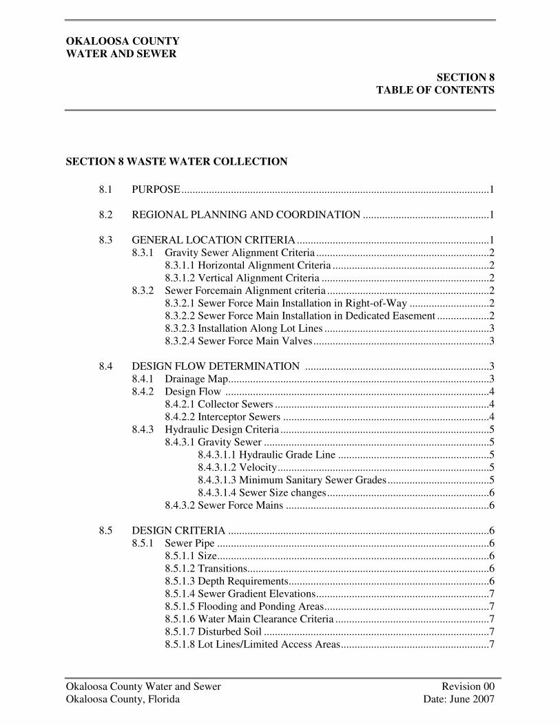
OKALOOSA COUNTY WATER AND SEWER
SECTION 8 TABLE OF CONTENTS
Okaloosa County Water and Sewer Revision 00 Okaloosa County, Florida Date: June 2007
SECTION 8 WASTE WATER COLLECTION 8.1 PURPOSE................................................................................................................1 8.2 REGIONAL PLANNING AND COORDINATION ..............................................1 8.3 GENERAL LOCATION CRITERIA......................................................................1 8.3.1 Gravity Sewer Alignment Criteria ...............................................................2 8.3.1.1 Horizontal Alignment Criteria .........................................................2 8.3.1.2 Vertical Alignment Criteria .............................................................2 8.3.2 Sewer Forcemain Alignment criteria ...........................................................2 8.3.2.1 Sewer Force Main Installation in Right-of-Way .............................2 8.3.2.2 Sewer Force Main Installation in Dedicated Easement ...................2 8.3.2.3 Installation Along Lot Lines ............................................................3 8.3.2.4 Sewer Force Main Valves................................................................3 8.4 DESIGN FLOW DETERMINATION ...................................................................3 8.4.1 Drainage Map...............................................................................................3 8.4.2 Design Flow ................................................................................................4 8.4.2.1 Collector Sewers ..............................................................................4 8.4.2.2 Interceptor Sewers ...........................................................................4 8.4.3 Hydraulic Design Criteria ............................................................................5 8.4.3.1 Gravity Sewer ..................................................................................5 8.4.3.1.1 Hydraulic Grade Line .......................................................5 8.4.3.1.2 Velocity.............................................................................5 8.4.3.1.3 Minimum Sanitary Sewer Grades.....................................5 8.4.3.1.4 Sewer Size changes...........................................................6 8.4.3.2 Sewer Force Mains ..........................................................................6 8.5 DESIGN CRITERIA ...............................................................................................6 8.5.1 Sewer Pipe ...................................................................................................6 8.5.1.1 Size...................................................................................................6 8.5.1.2 Transitions........................................................................................6 8.5.1.3 Depth Requirements.........................................................................6 8.5.1.4 Sewer Gradient Elevations...............................................................7 8.5.1.5 Flooding and Ponding Areas............................................................7 8.5.1.6 Water Main Clearance Criteria ........................................................7 8.5.1.7 Disturbed Soil ..................................................................................7 8.5.1.8 Lot Lines/Limited Access Areas......................................................7

WASTEWATER COLLECTION
Okaloosa County Water and Sewer Revision 00 Okaloosa County, Florida Date: June 2007
8.5.1.9 Encasements.....................................................................................7 8.5.2 Manholes......................................................................................................7 8.5.2.1 Manhole Locations...........................................................................7 8.5.2.2 Maximum Manhole Spacing............................................................8 8.5.2.3 Manhole Diameter ...........................................................................8 8.5.2.4 Water Tightness ...............................................................................8 8.5.2.5 Drop Inlets .......................................................................................8 8.5.2.6 Manhole Collars...............................................................................8 8.5.2.7 Manhole Inverts ...............................................................................9 8.5.3 Laterals.........................................................................................................9 8.5.3.1 Minimum Size and Grade ................................................................9 8.5.3.2 Lateral Connections .........................................................................9 8.5.3.3 Lateral Location ...............................................................................9 8.5.4 Flotation .......................................................................................................9 8.5.5 Concrete Encasements ...............................................................................10 8.5.6 Encasement Requirements .........................................................................10 8.5.6.1 General ...........................................................................................10 8.5.6.2 Encasement Pipe ............................................................................10 8.5.6.3 Encasement Spacers.......................................................................10 8.5.6.4 Encasement Ends ...........................................................................10 8.5.7 Railroad Crossings .....................................................................................11 8.5.7.1 Criteria Coordinate With Railroad Owner ....................................11 8.5.7.2 Railroad Conflict Drawings ...........................................................11 8.5.8 Highway Crossings ....................................................................................11 8.5.9 Interruption of Existing Sewer Service......................................................12 8.5.10 Trench Preparation.....................................................................................12 8.5.10.1 Excavation....................................................................................12 8.5.10.2 Sheeting and Bracing ...................................................................13 8.5.10.3 Dewatering...................................................................................13 8.5.11 Pipe Line Construction ..............................................................................13 8.5.11.1 Pipe Laying ..................................................................................13 8.5.11.2 Backfilling....................................................................................14 8.6 MATERIAL REQUIREMENTS...........................................................................14 8.6.1 Inspection of Materials ..............................................................................14 8.6.2 Pipe ............................................................................................................14 8.6.2.1 Ductile Iron Pipe ............................................................................14 8.6.2.2 Plastic Pipe (8" - 12") ....................................................................14 8.6.3 Laterals.......................................................................................................15 8.6.4 Fittings .......................................................................................................15 8.6.4.1 Iron Fittings....................................................................................15 8.6.4.2 Plastic Fittings (2" and smaller).....................................................15 8.6.5 Couplings and Connectors .........................................................................15 8.6.6 Epoxy Coatings..........................................................................................15 8.6.6.1 Concrete and Masonry ...................................................................15 8.6.6.2 Ductile Iron ....................................................................................16
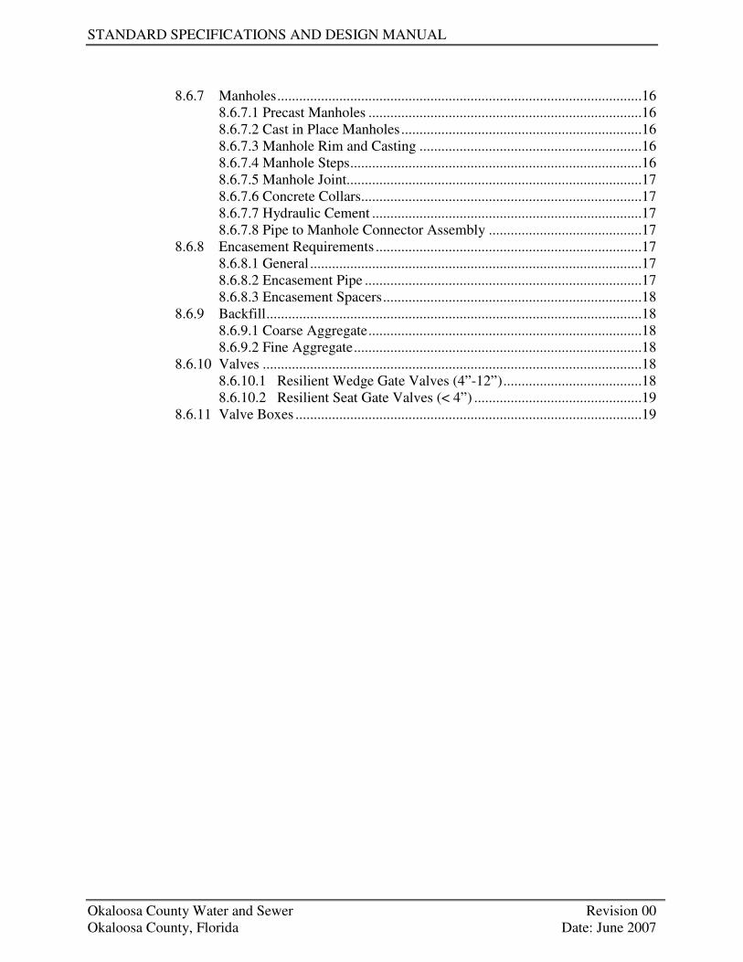
STANDARD SPECIFICATIONS AND DESIGN MANUAL
Okaloosa County Water and Sewer Revision 00 Okaloosa County, Florida Date: June 2007
8.6.7 Manholes....................................................................................................16 8.6.7.1 Precast Manholes ...........................................................................16 8.6.7.2 Cast in Place Manholes..................................................................16 8.6.7.3 Manhole Rim and Casting .............................................................16 8.6.7.4 Manhole Steps................................................................................16 8.6.7.5 Manhole Joint.................................................................................17 8.6.7.6 Concrete Collars.............................................................................17 8.6.7.7 Hydraulic Cement ..........................................................................17 8.6.7.8 Pipe to Manhole Connector Assembly ..........................................17 8.6.8 Encasement Requirements .........................................................................17 8.6.8.1 General ...........................................................................................17 8.6.8.2 Encasement Pipe ............................................................................17 8.6.8.3 Encasement Spacers.......................................................................18 8.6.9 Backfill.......................................................................................................18 8.6.9.1 Coarse Aggregate...........................................................................18 8.6.9.2 Fine Aggregate...............................................................................18 8.6.10 Valves ........................................................................................................18 8.6.10.1 Resilient Wedge Gate Valves (4”-12”)......................................18 8.6.10.2 Resilient Seat Gate Valves (< 4”) ..............................................19 8.6.11 Valve Boxes ...............................................................................................19


OKALOOSA COUNTY WATER AND SEWER
SECTION 8 WASTEWATER COLLECTION
Okaloosa County Water and Sewer 8-1 Revision 00 Okaloosa County, Florida Date: June 2007
8.1 PURPOSE
This section establishes the minimum standards and technical design criteria for sanitary sewer collection systems within Okaloosa County Water and Sewer service area. Adherence to these standards will expedite review and approval of plans. Any departure from these design requirements should be brought to the attention of Okaloosa County Water and Sewer Engineer and discussed prior to submission of plans for approval. Such departure shall be documented and justified. This section shall be coordinated and implemented with Section 11.
8.2 REGIONAL PLANNING AND COORDINATION
The County desires to address sewer system expansion on regional basis to eliminate the proliferation of small lift stations and gravity interceptors. Therefore, to maximize the efficiency of the OCWS sewer system, sewer system development shall consider the affects that future development of the surrounding areas within the draining basin could have on the design of the collective, conveyance, and pumping systems. Developers shall coordinate with OCWS to evaluate potential opportunities to upsize proposed facilities to serve future areas on a regional basis. Refer to the requirements presented in Section 11, as well as the requirements of the Okaloosa County Land Development Code.
8.3 GENERAL LOCATION CRITERIA
Sewers shall be located using sound Engineering judgment to determine the most cost-effective and environmentally sensitive alignment which best serves the needs of the entire tributary area. Additionally, it is imperative that all alternatives worthy of consideration receive maximum and equal consideration with regard to environmental impact. The cost for acquisition of easements can be significant; therefore, sewers should be located within existing easements and right-of-ways whenever feasible and practical. Whenever possible, sewers in subdivision construction projects shall be located in the street right of way. If the sewer main is installed parallel to a state road or highway, the sewers shall be located outside of State right of ways in dedicated easements. However, if OCWS determines that it is not practical to locate sewers in dedicated easements, OCWS may approve locating sewers in State right of ways on a case-by-case basis. When selecting the sewer alignment, consideration shall be given, but shall not be limited to, the following general location criteria: • Elevation requirements necessary to provide appropriate service with due consideration of
sanitary facilities in basements. • Environmentally sensitive areas and constraints such as creeks, wetlands, trees, protected
habitats, etc.
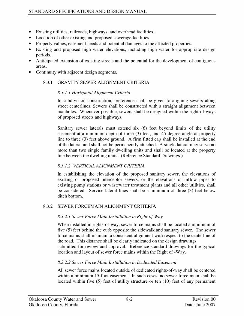
STANDARD SPECIFICATIONS AND DESIGN MANUAL
Okaloosa County Water and Sewer 8-2 Revision 00 Okaloosa County, Florida Date: June 2007
• Existing utilities, railroads, highways, and overhead facilities. • Location of other existing and proposed sewerage facilities. • Property values, easement needs and potential damages to the affected properties. • Existing and proposed high water elevations, including high water for appropriate design
periods. • Anticipated extension of existing streets and the potential for the development of contiguous
areas. • Continuity with adjacent design segments.
8.3.1 GRAVITY SEWER ALIGNMENT CRITERIA
8.3.1.1 Horizontal Alignment Criteria
In subdivision construction, preference shall be given to aligning sewers along street centerlines. Sewers shall be constructed with a straight alignment between manholes. Whenever possible, sewers shall be designed within the right-of-ways of proposed streets and highways. Sanitary sewer laterals must extend six (6) feet beyond limits of the utility easement at a minimum depth of three (3) feet, and 45 degree angle at property line to three (3) feet above ground. A firm fitted cap shall be installed at the end of the lateral and shall not be permanently attached. A single lateral may serve no more than two single family dwelling units and shall be located at the property line between the dwelling units. (Reference Standard Drawings.)
8.3.1.2 VERTICAL ALIGNMENT CRITERIA
In establishing the elevation of the proposed sanitary sewer, the elevations of existing or proposed interceptor sewers, or the elevations of inflow pipes to existing pump stations or wastewater treatment plants and all other utilities, shall be considered. Service lateral lines shall be a minimum of three (3) feet below ditch bottom.
8.3.2 SEWER FORCEMAIN ALIGNMENT CRITERIA
8.3.2.1 Sewer Force Main Installation in Right-of-Way
When installed in rights-of-way, sewer force mains shall be located a minimum of five (5) feet behind the curb opposite the sidewalk and sanitary sewer. The sewer force mains shall maintain a consistent alignment with respect to the centerline of the road. This distance shall be clearly indicated on the design drawings submitted for review and approval. Reference standard drawings for the typical location and layout of sewer force mains within the Right of -Way.
8.3.2.2 Sewer Force Main Installation in Dedicated Easement
All sewer force mains located outside of dedicated rights-of-way shall be centered within a minimum 15-foot easement. In such cases, no sewer force main shall be located within five (5) feet of utility structure or ten (10) feet of any permanent
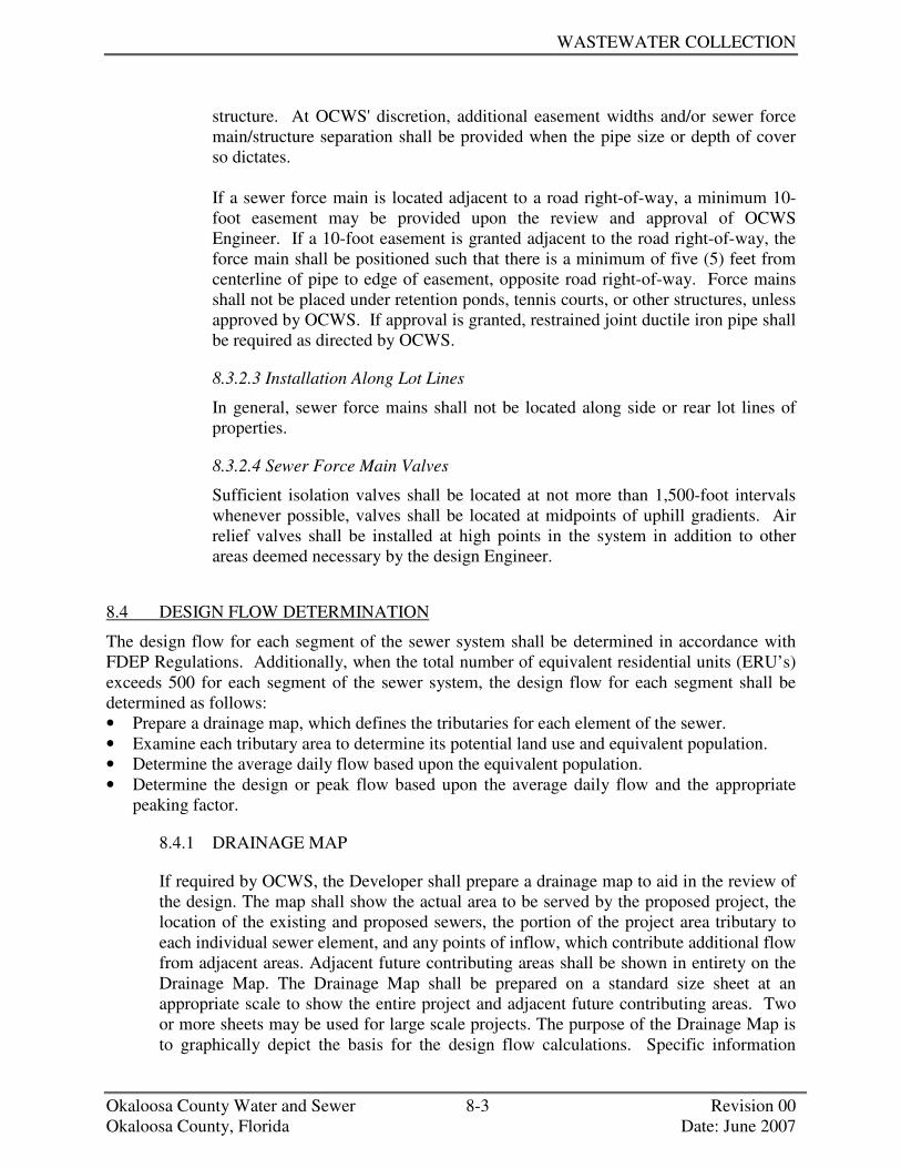
WASTEWATER COLLECTION
Okaloosa County Water and Sewer 8-3 Revision 00 Okaloosa County, Florida Date: June 2007
structure. At OCWS' discretion, additional easement widths and/or sewer force main/structure separation shall be provided when the pipe size or depth of cover so dictates. If a sewer force main is located adjacent to a road right-of-way, a minimum 10-foot easement may be provided upon the review and approval of OCWS Engineer. If a 10-foot easement is granted adjacent to the road right-of-way, the force main shall be positioned such that there is a minimum of five (5) feet from centerline of pipe to edge of easement, opposite road right-of-way. Force mains shall not be placed under retention ponds, tennis courts, or other structures, unless approved by OCWS. If approval is granted, restrained joint ductile iron pipe shall be required as directed by OCWS.
8.3.2.3 Installation Along Lot Lines
In general, sewer force mains shall not be located along side or rear lot lines of properties.
8.3.2.4 Sewer Force Main Valves
Sufficient isolation valves shall be located at not more than 1,500-foot intervals whenever possible, valves shall be located at midpoints of uphill gradients. Air relief valves shall be installed at high points in the system in addition to other areas deemed necessary by the design Engineer.
8.4 DESIGN FLOW DETERMINATION
The design flow for each segment of the sewer system shall be determined in accordance with FDEP Regulations. Additionally, when the total number of equivalent residential units (ERU’s) exceeds 500 for each segment of the sewer system, the design flow for each segment shall be determined as follows: • Prepare a drainage map, which defines the tributaries for each element of the sewer. • Examine each tributary area to determine its potential land use and equivalent population. • Determine the average daily flow based upon the equivalent population. • Determine the design or peak flow based upon the average daily flow and the appropriate
peaking factor.
8.4.1 DRAINAGE MAP
If required by OCWS, the Developer shall prepare a drainage map to aid in the review of the design. The map shall show the actual area to be served by the proposed project, the location of the existing and proposed sewers, the portion of the project area tributary to each individual sewer element, and any points of inflow, which contribute additional flow from adjacent areas. Adjacent future contributing areas shall be shown in entirety on the Drainage Map. The Drainage Map shall be prepared on a standard size sheet at an appropriate scale to show the entire project and adjacent future contributing areas. Two or more sheets may be used for large scale projects. The purpose of the Drainage Map is to graphically depict the basis for the design flow calculations. Specific information

STANDARD SPECIFICATIONS AND DESIGN MANUAL
Okaloosa County Water and Sewer 8-4 Revision 00 Okaloosa County, Florida Date: June 2007
required includes, but is not limited to, the following: • A key map showing the general location of the project area, including any areas not
within the project area but which contribute to the proposed system. • A general layout of the proposed system with the drainage area tributary to each
major element of the system defined. • The basis for determining the number of existing and future users and the equivalent
population for each drainage area, i.e., the number of single family or multi-family dwelling units; type and size of existing commercial, industrial and institutional users; and the number of acres of undeveloped land by zoning classification.
• A zoning designation for each drainage area. • A designation for each sewer line. • A numbering system for manholes, which shall be carried out to the computation
sheets. • All proposed sewer sizes. • The location of estimated or actual flow entering the proposed system from outside
areas, undeveloped or developed. These areas are to be shown in entirety on the Drainage Map and shall include the same types of information required for the proposed service area.
• An adequate number of spot elevations must be obtained in areas of undeveloped land to show the natural drainage of the area if necessary.
• An indication of the existing system's ability to receive the proposed flow with sufficient capacity.
• Identification of the boundaries of known or potential jurisdictional wetlands within the proposed development and outside areas, undeveloped and developed.
If requested, the Drainage Map and design calculations shall be presented for review with submittal of the preliminary and construction plans.
8.4.2 DESIGN FLOW
8.4.2.1 Collector Sewers
Collector sewers are primarily installed to receive wastewater directly from property service connections (laterals). A major change in land use within a tributary area can have a significant impact on the collector system’s ability to transport the necessary flow. Collector sewers should, therefore, be designed to transport the saturation population (final build out) flow, which might be expected during their service life (flowing full).
8.4.2.2 Interceptor Sewers
An interceptor sewer is a principal sewer to which collector sewers are tributary. All interceptor sewers should be designed for saturation population unless otherwise directed by OCWS. For a major industrial water user or undeveloped industrial land in the tributary area, OCWS will require the Engineer to supply an estimated average daily flow and potential wastewater constituent characterization in accordance with

WASTEWATER COLLECTION
Okaloosa County Water and Sewer 8-5 Revision 00 Okaloosa County, Florida Date: June 2007
Ordinance 98-3.
8.4.3 HYDRAULIC DESIGN CRITERIA
8.4.3.1 Gravity Sewer
Mannings equation shall be used to determine proper pipe size and slope to transport the design flow. Design shall be for full flow at saturation conditions (include a peaking factor of 3) with the following characteristics: • Roughness coefficient n = 0.013 (Sanitary Sewers Only- Ten State
(Standards)* • Minimum velocity v = 2 feet/second • Minimum pipe size D = 8 inches • Minimum acceptable grades (See 8.4.3.1.3)
* Due to potential of a slime layer build up in a sewer line, the referenced roughness
coefficient shall be the only one used in calculations.
8.4.3.1.1 Hydraulic Grade Line
The hydraulic grade line should not rise above the crown of the sewer pipe. When critical, the hydraulic grade line shall be computed to show its elevation at manholes, transition structures, and junction points of flow in pipes, and shall provide for the losses and the differences in elevation. If velocity entering a manhole is above critical, the hydraulic grade line must be computed to ensure that no service connections arc surcharged. The pipe exiting the manhole must be adjusted in elevation to ensure that the energy gradient remains level across the manhole.
8.4.3.1.2 Velocity
All gravity sanitary sewers shall be designed to carry the design flow (including any peaking factor) at a minimum velocity of 2.0 feet per second. The maximum allowable design velocity allowed shall be 15 feet per second based on the design flow. When severe topographic or other unusual conditions require a design velocity greater than 10 feet per second, the hydraulic design and pipe material must he specifically approved in writing by OCWS Engineer.
8.4.3.1.3 Minimum Sanitary Sewer Grades
The minimum acceptable grades for various sewer main sizes are indicated below:

STANDARD SPECIFICATIONS AND DESIGN MANUAL
Okaloosa County Water and Sewer 8-6 Revision 00 Okaloosa County, Florida Date: June 2007
MAIN SIZE MINIMUM ACCEPTABLE GRADE
8" 0.50% 5' per 1000 10" 0.30% 2.8' per 1000' 12" 0.22% 2.2' per 1000'
OTHER AS DIRECTED BY THE OCWS ENGINEER
8.4.3.1.4 Sewer Size Changes
When increasing the sewer size by 6 inches or less, crown elevations shall match at the centerline of the manhole.
When increasing the sewer size by more than 6 inches, the springlines of the smaller and larger sewer shall match at the centerline of the manhole. However, for the hydraulic design calculations, the Design Engineer shall match crown elevations at the centerline of the manhole by raising the elevation of the smaller sewer.
8.4.3.2 Sewer Force Mains
Hazen Williams equation shall be used to determine proper pipe size to transport the design flow. Design shall be for full flow at saturation conditions (include a peaking factor of 3) with the following characteristics: • Roughness coefficient C=120 to 140, as appropriate • Minimum velocity v = 2 feet/second • Maximum velocity v = 10 feet/second
8.5 DESIGN CRITERIA
8.5.1 SEWER PIPE
8.5.1.1 Size
The minimum allowable inside diameter for sewer pipe, other than property service connections, shall be 8 inches. All single dwelling laterals shall have a minimum inside diameter of 4 inches; however, commercial or industrial connections shall be individually considered.
8.5.1.2 Transitions
Where ductile iron or plastic composite pipe connects to another pipe material (i.e., clay, concrete, etc.) a concrete collar and an appropriate fitting for joining the two materials shall be used.
8.5.1.3 Depth Requirements
If the grade at any time (during or after) construction is less than 3 feet from the top of the sanitary sewer pipe then ductile iron pipe will also be required.

WASTEWATER COLLECTION
Okaloosa County Water and Sewer 8-7 Revision 00 Okaloosa County, Florida Date: June 2007
Composite plastic pipe can be used in areas where the cover above the pipe is in the range of 3 to 20 feet.
8.5.1.4 Sewer Gradient Elevations
All sewer gradient elevations shall be referenced to the North American Vertical Datum specified in sections. When connecting into or extending existing sewer facilities that were constructed using another datum, an election equation shall be shown on the plans. Datum shall be verified by a licensed land surveyor.
8.5.1.5 Flooding and Ponding Areas
The top of sanitary manhole elevations shall be a minimum of 2 feet above existing, proposed, or projected 100-year high water elevations. Relocate manholes when this minimum elevation causes the manhole to be above the natural ground creating obstructive mounds.
8.5.1.6 Water Main Clearance Criteria
The minimum horizontal clearance between the sewer and water mains shall be 10 feet or current FDEP Standards. The vertical clearance shall be at least 18 inches or current FDEP Standards. If at all possible, the sewer shall be located below the water main. Should it become necessary for the sewer to cross over the water main, special precautions will be required. Such cases shall require review and written approval by County.
8.5.1.7 Disturbed Soil
Ductile iron pipe shall be required in all fill areas and areas of disturbed ground.
8.5.1.8 Lot Lines/Limited Access Areas
If approved by OCWS Director, all sewer mains located along lot lines or between areas of limited access shall be D.I. from property line to property line. When it becomes necessary to run a sanitary sewer along lot lines or between adjacent streets, no offsets unless approved by OCWS will be allowed in the sanitary sewer line. Unless approved by OCWS Director, no gravity sewers or force mains may be located along lot lines or rear lot lines.
8.5.1.9 Encasements
Ductile iron pipe will be required in all encasements. Sanitary sewer mains that run through storm sewer, storm boxes, other utility mains, boxes, manholes or conduits shall be ductile iron and required to be encased.
8.5.2 MANHOLES
8.5.2.1 Manhole Locations
Manholes shall be required at the following: • Changes in sewer grades or alignment.

STANDARD SPECIFICATIONS AND DESIGN MANUAL
Okaloosa County Water and Sewer 8-8 Revision 00 Okaloosa County, Florida Date: June 2007
• Sewer junctions. • Where required not to exceed the maximum manhole spacing. • Changes in sewer diameters. • Termination points. The exact location of the terminal manhole in each sewer
line shall be based on many factors including manhole spacing, driveway locations, the position of improvements on the lots being served, and the location of present temporary sanitary facilities, such as septic tanks, etc. A definitive single policy cannot be established to cover all circumstances, although the sewer line would normally terminate a minimum of 25 feet past the lot line of the last property served. This is to allow enough room for the last lot to have a wye and lateral run into the sanitary sewer main without encroaching adjacent property.
8.5.2.2 Maximum Manhole Spacing
The maximum manhole spacing distances shall be 400 feet for all new sanitary sewer collection system construction. When certain conditions warrant, such as the elimination of a manhole, the manhole spacing can be exceeded with the approval of OCWS' Engineer.
8.5.2.3 Manhole Diameter
The minimum diameter of a manhole shall be 4 feet unless otherwise directed by OCWS' Engineer. Regardless of the recommendations offered, all manholes shall be checked to ensure that sufficient wall is supplied between pipe openings to meet all pre-cast manhole criteria.
8.5.2.4 Water Tightness
Watertight manholes, covers, and water seal inserts (rain stoppers) are to be used whenever the manhole covers may be flooded by street runoff or anticipated high water.
8.5.2.5 Drop Inlets
Where the distance between a manhole invert and the line coming into the manhole is greater than 6 inches (0.5 ft) the grade of the incoming line shall be changed to bring this distance down to 6 inches or a drop connection shall be installed (except youthful lines 10 inches or greater where invert may match crown of said youthful). The grade distance between the influent and effluent shall be 6 inches (0.5 ft) or less, except for standard drop connection construction. The minimum distance (from manhole invert to invert of incoming line) required for a drop connection is 22 inches. This is the distance needed for installing a required Memphis tee and ¼ bend.
8.5.2.6 Manhole Collars
A 6-inch collar shall be used when it is absolutely certain the manhole rim will not be lowered in the future. When it is anticipated that the manhole rim may be lowered, a 12-inch or greater collar shall be specified.

WASTEWATER COLLECTION
Okaloosa County Water and Sewer 8-9 Revision 00 Okaloosa County, Florida Date: June 2007
Manholes will be adjusted to the final grade by pre-cast extensions. Manhole extensions will not exceed more than 1.5 feet of chimney as measured from the top of the manhole rim to the point where the manhole starts to increase in size.
8.5.2.7 Manhole Inverts
8.5.3 LATERALS
Each platted lot shall have its own individual sanitary sewer connection. Laterals should serve no more than two single family owned units. Each duplex, apartment, or condominium that has the potential to be sold as an individual dwelling on its own lot shall have a separate sanitary sewer connection. If a single-family dwelling is built upon several lots, only one sanitary sewer lateral will be required.
8.5.3.1 Minimum Size and Grade
Sanitary sewer laterals shall be a minimum of 4 inches in diameter and run perpendicular to the sanitary sewer line. Laterals located in cul-de-sacs are not required to run perpendicular to the sewer main. Laterals shall have a minimum slope of 1/8-inch per foot (1%) for laterals. However, in all cases, the invert elevation of the property lateral at the easement or property line shall be equal to or higher than the crown of the sewer.
8.5.3.2 Lateral Connections
Lateral connections to the main collector pipe shall be made using a wye installed at an angle no greater than 45 degrees from the horizontal centerline. Lateral Stacks (installing wyes at 90 degrees from the horizontal centerline) are prohibited.
8.5.3.3 Lateral Location
The sanitary sewer lateral shall extend perpendicular from the main to the street right-of-way or utility easement if greater. Extend the service lateral at 45 degrees at the ROW or easement line and extend above finished grade 3.0’. At the property line, the sanitary sewer lateral shall be placed no shallower than 3 feet and no deeper than 6 feet deep with respect to final grade, unless otherwise approved by OCWS.
Sanitary sewer laterals on lots that have less than 15’ of street frontage shall be extended on to property to within 5 feet of the building line.
When a sewer main runs along a lot line, laterals shall be stubbed outside building limits to prevent any possible conflict with the building slab.
8.5.4 FLOTATION
All sewers and sewer structures to be constructed where high groundwater conditions

STANDARD SPECIFICATIONS AND DESIGN MANUAL
Okaloosa County Water and Sewer 8-10 Revision 00 Okaloosa County, Florida Date: June 2007
exist or where flooding of the trench is anticipated shall be designed to prevent flotation or excessive pipe flexing. In these conditions, ductile iron pipe shall be used.
8.5.5 CONCRETE ENCASEMENTS
Concrete encasement shall extend a minimum length of 2 feet beyond the point where a minimum 3 foot depth of cover is reached or to a point 5 feet beyond the tops of banks when crossing a ditch or stream. Encasements may be used when it is necessary to prevent floatation, when crossing streams, ditches, or existing storm drains, where soil conditions may indicate the possibility of heavy erosion, where crossing over or under utilities with less than 2-feet of clearance, or in areas where the sewer has less than the required minimum cover. Concrete encasement is not acceptable unless specifically approved by OCWS’ Engineer.
8.5.6 ENCASEMENT REQUIREMENTS
8.5.6.1 General
Encasement is required when crossing all State highways, railroad, and some County and City roadways, which have excessive traffic flow or other critical situations (such as protecting building foundations). Encasement and mains shall cross the roadway and/or railroads as near as possible perpendicular to the roadbed. In all cases the agency requiring the encasement shall have the final approval of the Engineering design. Ductile iron pipe will be required in all encasements.
8.5.6.2 Encasement Pipe
Pipe to be installed under pavement where open trenching is not permitted shall be installed through steel casing, which has been jacked and bored. Casing shall extend out past both sides of pavement a minimum of 3 feet or past toe of slope whichever is greater.
8.5.6.3 Encasement Spacers
Sewer mains shall be pushed through the encasement piping on spacers placed no more than 10 feet apart. A minimum of two spacers/runners per joint of pipe shall be required. The spacer shall have a clearance range of 1 to 1.5 inches of clearance between the spacer and the inside of the encasement piping. Spacers shall be required in the first foot of each end of the encasement.
8.5.6.4 Encasement Ends
All casing ends shall be sealed with an end seal as manufactured by Pipeline Seal and Insulators, Inc. or equal (See Miscellaneous Detail 120).

WASTEWATER COLLECTION
Okaloosa County Water and Sewer 8-11 Revision 00 Okaloosa County, Florida Date: June 2007
8.5.7 RAILROAD CROSSINGS
8.5.7.1 Criteria Coordinate with railroad owner
In addition to the individual railroad’s design requirements the following criteria shall be strictly adhered to when the planning for sewer construction affects railroad rights-of-way and facilities (railroad may specify more stringent requirements): • Sewers shall cross tracks at an angle as close to 90 degrees as practical, but
preferably never less than 45 degrees. Sewers shall not be placed under railroad bridges where there is a likelihood of restricting the required waterway area of the bridge or where there is a possibility of endangering the foundations.
• Sewer lines crossing under railroad tracks and rights-of-way shall be bored and jacked casings unless the railroad company grants written permission for open-cut construction.
• Sewer lines laid longitudinally along railroad rights-of-way shall be located as far as practical from any tracks or other important structures. If located within 25 feet of the centerline of any track, or should there be danger of damage from leakage to any bridge, building or other important structure, the sewer shall be encased.
• When placed along railroad rights-of-way, the top of the pipe shall have a minimum cover of 4 feet.
8.5.7.2 Railroad Conflict Drawings
Railroad conflict drawings shall conform to the following criteria: • Drawings shall be prepared to scale showing the relationship between the
proposed sewer and the railroad, angle of crossing, location of utilities, original survey station of the railroad (when available), right-of-way lines, topography and general layout. The profile established from a field survey shall show the sewer in relation to the actual ground and tracks. The limits of boring or tunneling by station, sewer line soundings and borings and all other pertinent information shall be shown on the drawing.
• Railroad conflict drawings shall be submitted along with a complete questionnaire, which shall be furnished by the railroad company.
8.5.8 HIGHWAY CROSSING
Sewer pipe installations under State, County, or City maintained roadways, which are designated by their governing agencies, shall meet the following requirements (more stringent criteria may be required on a project specific basis): • Sewers shall cross roadways at an angle as close to 90 degrees as practical, but
preferably never less than 45 degrees. Sewers shall not be placed under roadway bridges where there is a likelihood of restricting the required area of the bridge or where there is a possibility of endangering the foundations.
• Borings under roadways shall have a minimum depth of 4 feet from the surface elevation to the top of the boring. The top of the tunnel lining shall not be above the

STANDARD SPECIFICATIONS AND DESIGN MANUAL
Okaloosa County Water and Sewer 8-12 Revision 00 Okaloosa County, Florida Date: June 2007
invert of existing or proposed ditches. • Borings under roadways shall extend a minimum of 10 feet outside the existing
pavement, as measured at right angles to the roadway, or to the toe of the slope when the roadway is on fill and the toe of slope exceeds 10 feet outside the existing paving.
• Sewer lines laid in a longitudinal direction on highway rights-of-way shall be located a sufficient distance from the edge of the pavement to allow adequate working room and to provide maximum safety to the motorist when the roadway is to remain open to traffic. Those sewer lines within the roadway rights-of-way, but not located under paved areas, shall have no less than 5 feet of cover.
• Metallic wire shall be laid in the trench above ALL thermoplastic pipes from edge of pavement to the right-of-way line or from end of tunnel to right-of-way line on all crossings of State Right of Ways.
8.5.9 INTERRUPTION OF EXISTING SEWER SERVICE
Existing sewer customers shall not be placed out of service in order to connect or lay new sewer piping. The Contractor shall coordinate with the Board all service interruptions prior to construction. The Contractor shall be responsible for providing temporary service through by-pass pumping if necessary to all of the County's customers affected by the construction.
8.5.10 TRENCH PREPARATION
8.5.10.1Excavation
All excavation shall be done in accordance with OSHA Code of Regulation Part 1926 (latest revision). A trench shall be opened so that the pipe can be installed to the alignment and depth required. It shall be excavated only so far in advance of pipe laying as necessary. The trench shall be excavated to the depth required so as to provide a uniform and continuous bearing support for the pipe on undisturbed ground. Bell holes shall be provided at each joint to permit jointing to be made and inspected properly. During excavation, if ashes, cinders, muck or other organic material considered unstable is uncovered at the bottom of the trench at sub grade, it shall be removed and backfilled with approved material for a depth not less than 12 inches. This material shall be tamped in layers of 6 inches to provide a uniform and continuous bearing characteristic of that area’s soil condition. Where the bottom of the trench at subgrade consists of unstable material to such a degree that it cannot be removed and replaced with an approved material to support the pipe properly, a suitable foundation shall be constructed. Excavated material shall be piled in such a manner that it will not endanger work, obstruct natural watercourse, sidewalks or driveways. Fire hydrants, valve boxes, or other utility controls shall be left unobstructed and accessible at all times. Street gutters shall be kept clear or other satisfactory provisions made for street drainage. All surface materials, which are suitable for

WASTEWATER COLLECTION
Okaloosa County Water and Sewer 8-13 Revision 00 Okaloosa County, Florida Date: June 2007
reuse in restoring the surface, shall be kept separate from the excavated materials.
8.5.10.2 Sheeting and Bracing
Open cut trenches shall be sheeted and braced as required by OSHA Code of Regulations Part 1926 (latest revision) and as may be necessary to protect life, property or the work. Trench bracing may be removed after the backfilling has been completed or has been brought up to such an elevation as to permit its safe removal. The use of a trenching box may be used in place of sheeting and bracing as long as said box is in compliance with above referenced OSHA Code.
8.5.10.3 Dewatering
Water shall not be allowed in the trench at any time. An adequate supply of well points, headers and pumps, all in first class operating condition, shall be used to remove the ground water. The use of gravel and pumps shall also be an acceptable means of removing the water on a case-by-case basis as approved by the OCWS. At no time shall any pumps emit an unacceptable noise level as determined by the OCWS’ Engineer or Contractor will be required to shut down pumping operations. The trench shall be excavated no more than the available pumping facilities are capable of handling. The discharge from pumps shall be routed to settling basins or other acceptable erosion and sedimentation control devices prior to discharging to natural or existing drainage channels or storm sewers. Any and all permits required for Dewatering are the responsibility of the Contractor and shall be obtained prior to commencement of construction.
8.5.11 PIPE LINE CONSTRUCTION
8.5.11.1 Pipe Laying
All sewer mains, laterals, and appurtenances shall be installed as specified in these technical provisions, manufacturer’s recommendations, and in accordance with the approved plans and appropriate standard detail sheets as provided herein. The bottom of the trench shall not be excavated below the specified grade. If undercutting occurs, the bottom of the trench shall be brought up to the original grade with approved material, thoroughly compacted as directed by OCWS' Engineer and/or his representative. Before placing pipe into the trench, the outside of the spigot and the inside of the bell shall be wiped clean and dry before applying lubrication. Every precaution shall be taken to prevent foreign material from entering the pipe. During laying operations, no debris, tools, clothing or other material shall be placed in the pipe.
All slip joints shall be made up in strict accordance with the manufacturer's specifications. The bell shall be carefully cleaned before the gasket is inserted.

STANDARD SPECIFICATIONS AND DESIGN MANUAL
Okaloosa County Water and Sewer 8-14 Revision 00 Okaloosa County, Florida Date: June 2007
After placing a length of pipe in the trench, the spigot end shall be entered in the bell, the pipe forced home, and brought to correct alignment.
8.5.11.2 Backfilling
All backfilling material shall be free from cinders, ashes, refuse, vegetable or organic material, boulders, rocks, stones of other material which is considered unsuitable. The Contractor shall not backfill any connection or appurtenances that require OCWS’ inspection. Failure to provide the opportunity for inspection shall be grounds or the removal and replacement of all disputed items. All such inspections shall be scheduled two working days in advance.
8.6 MATERIAL REQUIREMENTS
8.6.1 INSPECTION OF MATERIALS
All materials delivered to the job site are submitted to inspection by OCWS' representative. Any materials found during inspection or during the progress of the work to be defective or not meeting specifications shall be rejected and removed from the job site without delay. Materials and/or work not inspected by the Board’s representative prior-to installation shall be uncovered by the Contractor at his expense in order to verify compliance. Copies of the Packing List shall be furnished on demand. All materials used for sanitary sewer construction shall be new and of domestic origin. No used material shall be allowed.
8.6.2 PIPE
8.6.2.1 Ductile Iron Pipe
Ductile iron sewer pipe shall be push-on joint in accordance with ASTM A 746-latest version and ANSI/AWWA Cl11/A21.l1. Pipe wall thickness shall be in accordance to bury depth as specified in above referenced AWWA latest edition. The pipe shall be protected with epoxy coatings as provided by Protecto 401 by Vulcan Painters, Birmingham, Alabama or approved equal. All ductile iron pipe for underground installation shall be outside coated with Industry Standard bituminous material applied by means of airless spray or other factory approved method. Each pipe segment shall be clearly indentified as having the Protecto 401 coating.
8.6.2.2 Plastic Composite Pipe (8”— 12”)
PVC composite pipe shall be push-on joint in accordance with ASTM D2680-90 (latest version). Minimum pipe stiffness, when measured in accordance with ASTM D24 12, shall be 200 psi. The thermoplastic material shall meet or exceed the requirements of ASTM D1784. Contech Construction Products, Inc. Truss Pipe, a PVC composite pipe, has been approved for installation.

WASTEWATER COLLECTION
Okaloosa County Water and Sewer 8-15 Revision 00 Okaloosa County, Florida Date: June 2007
8.6.3 LATERALS
Laterals shall be solid wall PVC and be 4 inch conforming to the requirements of ASTM A746 or ASTM D3034. Solid wall lateral pipe shall be SDR 23.5.
8.6.4 FITTINGS
8.6.4.1 Iron Fittings
Fittings shall be ductile iron and shall be designated and manufactured in accordance with ANSI A21.1 latest version. Fittings shall be protected with an epoxy coating (Protecto 401 or equal) in accordance with ANSI/AWWA Cl04/A21.4.
8.6.4.2 Plastic Fittings (< 4 inches)
Pipe with diameters of less than 4 inches shall have PVC composite fittings that conform to ASTM D2680-80.
8.6.5 COUPLINGS AND CONNECTORS
Couplings and connectors may be used to join similar and dissimilar materials as well as pipes of the same diameter or of different diameters. Indiana Seal Flexible Couplings or Flex-Seal Couplings (Mission Rubber Co.) using series 300 stainless steel hose clamps shall be used.
8.6.6 EPOXY COATINGS
All manholes, ductile iron pipe, and other sewer system components on interceptor/outfall lines (sewer mains with diameters of 18” and greater) shall be protected from corrosion by the use of factory applied epoxy coatings. In addition to the epoxy coating requirement as described below, OCWS may extend the use of protective coatings to include the first two segments (or 500 ft. of sewer main) of any branch sewer emanating from the interceptor/outfall lines. OCWS further reserves the right to require protective coatings on any manhole, ductile iron pipe, or component of any collector line (less than 18” in diameter) as is deemed necessary by OCWS' Engineer.
8.6.6.1 Concrete and Masonry
8.6.6.1.1 Exterior
Epoxy coatings on concrete and masonry (i.e. manholes, concrete pipes, etc.) shall be applied to the exterior with a polyamide coal tar epoxy, Series 46H-413 Hi-Build Tnemec-Tar or approved equal. A seal coat of epoxy shall be applied to the exterior of the structure per the manufacture’s recommendations.

STANDARD SPECIFICATIONS AND DESIGN MANUAL
Okaloosa County Water and Sewer 8-16 Revision 00 Okaloosa County, Florida Date: June 2007
8.6.6.1.2 Interior
Following this review, OCWS may require the interior of concrete masonry structures (i.e. manholes, concrete pipe, etc.) to be coated using Sprayroq or equal. As a minimum, all manholes receiving force main discharge flows shall be coated as described above.
8.6.6.2 Ductile Iron
Epoxy coatings on ductile iron pipe and fittings shall have a ceramic epoxy lining on the interior and a bituminous coating on the exterior except for 6” back from the spigot end. The bituminous coating shall not be applied to the first 6” of the exterior of the spigot ends. The material used for the lining shall be a two component amine cured epoxy. Epoxy shall be Protecto 401 by Vulcan Painters, Birmingham, Alabama or approved equal. The epoxy shall be applied to a thickness of at least 40 mils.
8.6.7 MANHOLES
8.6.7.1 Precast Manholes
Precast manholes shall be reinforced concrete conforming to the requirements of ASTM C478. The concrete when tested in compression shall be not less than 4000 psi.
8.6.7.2 Cast in place Manholes
Cast in place manholes, saddle type (dog houses) shall not be used unless approved otherwise by OCWS’ Director.
8.6.7.3 Manhole Rim and Casting
Ferrous casting shall be of uniform quality, free from blowholes, shrinkage, distortion or other defects. Metal used in the manufacture of castings shall conform to ASTM A-48 (latest revision) Class 35B for Gray Iron. All castings shall be manufactured true to pattern; component parts shall fit together in a satisfactory manner. Component parts of a specified design shall be interchangeable. Round frames and covers shall have continuously machined bearing surfaces to prevent rocking and rattling. Tolerances shall be accepted foundry standards as outlined in the Iron Castings Handbook published by the American Cast Metals Institute (tolerances shall not exceed +/- 1/16 inch per foot of major dimension). Castings shall be coated with bituminous asphalt coating. All manhole covers shall have the following cast on the cover: Okaloosa County Sanitary Sewer. (Refer to detail sheet.)
8.6.7.4 Manhole Steps
Manhole steps shall be copolymer polypropylene plastic with ½” diameter grade 60 reinforcements and shall conform to ASTM C478. All steps shall be built into the walls of the precast sections in straight alignment so as to form a continuous
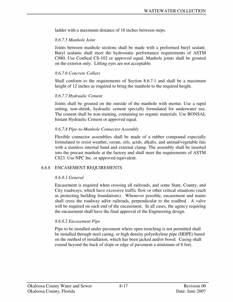
WASTEWATER COLLECTION
Okaloosa County Water and Sewer 8-17 Revision 00 Okaloosa County, Florida Date: June 2007
ladder with a maximum distance of 16 inches between steps.
8.6.7.5 Manhole Joint
Joints between manhole sections shall be made with a preformed butyl sealant. Butyl sealants shall meet the hydrostatic performance requirements of ASTM C880. Use ConSeal CS-102 or approved equal. Manhole joints shall be grouted on the exterior only. Lifting eyes are not acceptable.
8.6.7.6 Concrete Collars
Shall conform to the requirements of Section 8.6.7.1 and shall be a maximum height of 12 inches as required to bring the manhole to the required height.
8.6.7.7 Hydraulic Cement
Joints shall be grouted on the outside of the manhole with mortar. Use a rapid setting, non-shrink, hydraulic cement specially formulated for underwater use. The cement shall be non-staining, containing no organic materials. Use BONSAL Instant Hydraulic Cement or approved equal.
8.6.7.8 Pipe-to-Manhole Connector Assembly
Flexible connector assemblies shall be made of a rubber compound especially formulated to resist weather, ozone, oils, acids, alkalis, and animal/vegetable fats with a stainless internal band and external clamp. The assembly shall be inserted into the precast manhole at the factory and shall meet the requirements of ASTM C823. Use NPC Inc. or approved equivalent.
8.6.8 ENCASEMENT REQUIREMENTS
8.6.8.1 General
Encasement is required when crossing all railroads, and some State, County, and City roadways, which have excessive traffic flow or other critical situations (such as protecting building foundations). Whenever possible, encasement and mains shall cross the roadway ad/or railroads, perpendicular to the roadbed. A valve will be required on each end of the encasement. In all cases, the agency requiring the encasement shall have the final approval of the Engineering design.
8.6.8.2 Encasement Pipe
Pipe to be installed under pavement where open trenching is not permitted shall be installed through steel casing, or high density polyethylene pipe (HDPE) based on the method of installation, which has been jacked and/or bored. Casing shall extend beyond the back of slope or edge of pavement a minimum of 6 feet.

STANDARD SPECIFICATIONS AND DESIGN MANUAL
Okaloosa County Water and Sewer 8-18 Revision 00 Okaloosa County, Florida Date: June 2007
Casing size and thickness shall be as indicated below:
DIAMETER OF SEWER MAIN
(INCHES)
MINIMUM CASING
DIAMETER (INCHES)
MINIMUM CASING
THICKNESS (INCHES)
ASTM / AWWA STANDARD
4" 12" .25" ASTM A53 6" 14" .25" ASTM A53 8" 16" .25" ASTM A53
10" 18" .25" ASTM A53 12" 24" .375" ASTM A53
Larger than 12" As Approved by County Engineer
As Approved by County Engineer
As Approved by County Engineer
8.6.8.3 Encasement Spacers
Encasement spacers shall be as manufactured by Cascade Water Works Inc., Advanced Products and Systems Inc., or Pipeline Seal and Insulator Inc. Spacers to be stainless steel body with runners a minimum of 8” in length for piping under 12” in diameter.
8.6.9 BACKFILL
8.6.9.1 Coarse Aggregate
Coarse aggregate shall consist of naturally occurring materials such as gravel, or resulting from the crushing of parent rock, to include natural rock, slags, expanded clays and shales (lightweight aggregates), and other approved inert materials with similar characteristics, having hard, strong, durable particles, conforming to the specific requirements of Section 901 “Course Aggregate” of FDOT’s Standard Specifications.
8.6.9.2 Fine Aggregate
Fine aggregate shall consist of natural silica sand, screenings, local materials, or subject to approval, other inert materials with similar characteristics, or combination thereof, having hard, strong, durable particles, conforming to the specific requirements of Section 902 “Fine Aggregate” of FDOT’s Standard Specifications.
8.6.10 VALVES
8.6.10.1 Resilient Wedge Gate Valves (4” - 12”)
Gate valves on sewer force main size 4” to 12” in diameter shall incorporate resilient wedge gates with mechanical joint ends. All gate valves shall be of domestic origin and shall meet or exceed AWWA C-515 or C-509. Resilient wedges shall be of natural or synthetic rubber and be bonded or mechanically

WASTEWATER COLLECTION
Okaloosa County Water and Sewer 8-19 Revision 00 Okaloosa County, Florida Date: June 2007
attached to the gate using stainless steel hardware and shall be rated at a working pressure of 200 psi. The interior and exterior of the valve body shall be fusion-bonded epoxy coated in accordance with AWWA C-550 (latest edition) in order to provide a corrosion resistant seat, applied in a manner to withstand the action of line fluids and operation of the sealing gate under long-term service. Valve seats shall seal by compression only. Valves shall be supplied with 2” square operating nuts and shall be designed to provide a bubble or bottle tight seal regardless of direction of flow. Opening shall be in the counterclockwise direction. The following resilient wedge gate valves are accepted for installation:
MANUFACTURER MODEL NO.
American Flow Control Series 2500 Mueller A-2360
8.6.10.2 Resilient Seat Gate Valves (< 4”)
All gate valves < 4” located below grade must be ductile iron resilient wedge meeting or exceeding AWWA C515 standards, latest edition. All gate valves shall have a standard 2” operating nut and standard FPT openings. No bronze/brass type gate valves will be accepted in underground applications.
MANUFACTURER MODEL NO.
American Flow Control 502 Mueller A-2360
8.6.11 VALVE BOXES
Cast iron valve boxes shall be provided for all vales installed underground. The valve boxes shall be adjustable to fit the depth of earth covered over the valve and shall be designed so as to prevent the transmission of surface loads directly to the valve or piping. The valve boxes shall be manufactured of cast iron and shall be of the two piece design, screw type, including a bottom section and top section with lid cover. Only those valve boxes that are of domestic manufacture will be acceptable. The casting shall be manufactured of clean, even grain, gray cast iron with a minimum tensile strength of 21,000 psi. It shall be smooth, true to pattern, free from blowholes, sand holes, projections and other harmful defects. The seating surface of both the lid cover and the top section shall be cast so that the cover will not rock after it has been seated, and will fit tightly with no play. The Department reserves the right to require a certification of compliance from the manufacturer.

STANDARD SPECIFICATIONS AND DESIGN MANUAL
Okaloosa County Water and Sewer 8-20 Revision 00 Okaloosa County, Florida Date: June 2007
Valve box must be an integral unit that is telescopic and adjustable and shall house the entire valve and operator extension. Extension pieces, if required shall be ductile iron pipe. Valve box lids should have the work sewer cast on the top. All valve boxes located outside of roadway pavement shall have concrete pad (two foot to three foot diameter) poured around the box at finished grade level.
+++ END OF SECTION +++

SECTION 9
SEWER TESTING AND INSPECTION

OKALOOSA COUNTY WATER AND SEWER
SECTION 9 TABLE OF CONTENTS
Okaloosa County Water and Sewer Revision 00 Okaloosa County, Florida Date: June 2007
SECTION 9 SEWER TESTING AND INSPECTION 9.1 PURPOSE................................................................................................................1 9.2 GENERAL...............................................................................................................1 9.2.1 Visual Inspection .........................................................................................1 9.2.2 Low Pressure Air Test .................................................................................1 9.2.2.1 Air Test Procedure (Dry Conditions)...........................................2 9.2.2.2 Air Test Procedure (Wet Conditions) ..........................................3 9.2.3 Vacuum Testing of Manholes......................................................................4 9.2.3.1 Vacuum Testing Procedure............................................................4 9.3 SEQUENCE OF TESTING.....................................................................................5 9.4 TEST FAILURE ......................................................................................................5 9.5 MANDREL EQUIPMENT......................................................................................5 9.6 AIR/VACUUM TEST EQUIPMENT .....................................................................5 NEW CONSTRUCTION INSPECTION CHECKLIST .....................................................6


OKALOOSA COUNTY WATER AND SEWER
SECTION 9 SEWER TESTING AND INSPECTION
Okaloosa County Water and Sewer 9-1 Revision 00 Okaloosa County, Florida Date: June 2007
9.1 PURPOSE
This section outlines the requirements for acceptance testing of gravity sewer pipe (plastic composite and ductile iron).
9.2 GENERAL
Testing shall be accomplished through the combination of visual inspections, low pressure air tests, and leakage tests methods. Acceptance tests shall only be performed after all work adjacent to and over the pipeline has been completed. Backfilling, placement of fill, grading, initial/base layer of paving, concrete work, and any other superimposed loads shall be completed and in place prior to any testing. All testing shall be performed in the presence of OCWS representative, after the installation of all other utilities (including power poles). Tests performed in the absence of OCWS’s representative shall be considered invalid and shall be repeated at the Contractor’s expense.
9.2.1 VISUAL INSPECTION
OCWS’s representative shall visually inspect all gravity sewer pipe (plastic composite and ductile iron) installed to verify alignment and ensure the pipe is free from obstructions and debris. The Contractor shall ensure that survey staking is provided to identify easement locations, as well as, final location and grade of proposed culverts, storm drains, and ditches. Contractor shall call for a visual inspection when a maximum of 10 manholes have been installed and following installation of all laterals. The inspector shall use the sunlight or spotlight, and mirrors to “flash” the sewer pipe one section at a time. When the full diameter of the pipe is visible between adjacent manholes, the segment of piping is deemed properly aligned and free of sags and debris. If the segment of pipe fails the visual inspections, the pipe shall be cleaned and/or replaced and re-tested. Contractor shall provide a bill of materials of the installed pipeline at the time of the visual inspection. Contractor may be requested to excavate the pipe for inspection.
9.2.2 LOW-PRESSURE AIR TEST
On all sanitary sewer lines (plastic composite and ductile iron), including private sewer lines, the Contractor shall conduct a line acceptance test using low-pressure air testing. For ductile iron pipelines, test in accordance with the applicable requirements of ASTM C924. For PVC pipelines, test in accordance with ASTM F 1417-98 and UBPPA UNI-B-6.

STANDARD SPECIFICATIONS AND DESIGN MANUAL
Okaloosa County Water and Sewer 9-2 Revision 00 Okaloosa County, Florida Date: June 2007
For gasketed joint plastic composite pipe (Truss Pipe), it is often desirable to begin and finish a run with the factory bell in place (lay the upstream section of the pipe backwards) or coat the spigot ends at each manhole with a heavy bodied moisture cured urethane adhesive. Take care to coat both ends of spigot/spigot section entering the manhole. The Contractor shall furnish all labor, equipment, and any appurtenant items necessary to satisfactorily perform the vacuum test. All testing equipment shall be approved for vacuum testing manholes.
9.2.2.1 Air Test Procedure (Dry Conditions)
The following procedure shall be used during the low—pressure air testing of sewer mains located above the ground water table: • Isolate section of sewer by inflatable stoppers or other suitable test plugs. Plug
or cap the ends of all branches, laterals, tees, wyes, and stubs to be included in the test. Securely brace all plugs or caps to prevent blow-out. One of the plugs or caps should have an inlet tap, or other provision for connecting a hose to a portable air source.
(Note: Special attention should be placed on the exposed spigot end of composite plastic pipe. If not properly sealed, air can leak through the porous material in the pipe’s annulus.)
• Connect the air hose to the inlet tap. Add air slowly to the test section until the
pressure inside the pipe reaches 4.0 psig. • Allow the pressure to stabilize such that a pressure between 4.0 psig and 3.5
psig is maintained for at least two minutes. The pressure will normally drop slightly until equilibrium is obtained; however a minimum of 3.5 psig is required.
• Disconnect the air supply and decrease the pressure to 3.5 psig. before starting the test.
• Use the Time-Pressure Drop Method to determine if the segment of pipe is “Acceptable”. Determine the minimum acceptable time for a 1 psig. drop in pressure from 3.5 psig to 2.5 psig. Compare the minimum acceptable time to that actually observed in the field to determine if the rate of air loss is within acceptable limits. Minimum holding times are listed in the following table depending on length and size of mains.

SEWER INSPECTION AND TESTING
Okaloosa County Water and Sewer 9-3 Revision 00 Okaloosa County, Florida Date: June 2007
Minimum specified time required for a 1.0 psig pressure drop for size and length of pipe.
Specification Time for Length Shown (Minutes: Seconds) Pipe
Diameter (Inches) 100 ft 150 ft 200 ft 250 ft 300 ft 350 ft 400 ft 450 ft
8 7:34 7:34 7:34 7:34 7:36 8:52 10:08 9:24 10 9:26 9:26 9:26 9:53 9:52 13:51 15:49 17:48 12 9:20 9:20 9:24 14:15 17:05 19:56 22:47 25:38 15 14:10 14:10 17:48 22:15 26:42 31:09 35:35 40:04 18 17:00 19:13 25:38 32:03 38:27 44:52 51:16 57:41 21 19:50 26:10 34:54 43:37 52:21 61:00 69:48 78:31 24 22:47 34:9 45:34 56:58 68:22 79:46 91:10 102:33
9.2.2.2 Air Test Procedure (Wet Conditions)
All test procedures are measured as gage pressure, which is any pressure greater than atmospheric. Since water produces a pressure of 0.43 psig for every foot of depth over the main, air test pressures must be increased to offset the depth of groundwater over the sewer line. In areas where groundwater is known to exist, the Contractor shall install one-half inch diameter capped PVC pipe nipple, approximately 10" long, through the manhole wall on top of one of the sewer lines entering the manhole. This shall be done at the time the sewer line is installed. Immediately prior to performing the line acceptance test, the groundwater elevation shall be determined by removing the pipe cap, blowing air through the pipe nipple into the ground so as to clear it, and then connecting a clear plastic tube to the nipple. The hose shall be held vertically and a measurement of the height in feet of water over the invert of the pipe shall be taken after the water has stopped rising in the plastic tube. Multiply the height in feet above the pipe invert to the groundwater table by 0.43 psig/ft and add it to the required 3.5 psig minimum test pressure. For example, if the height of water is 9.5 feet, then the added pressure will be 0.43 psig/ft x 9.5 ft or 4.9 psig. This increases the test pressure from 3.5 psig to 8.4 psig and the 2.5 psig to 7.4 psig, respectively. The allowable drop of 1 psig for the time allowed as outlined in Table 1 still remains the same for 8.4 psig and the 2.5 psig to .4 psig, respectively. If however, the groundwater level is 2 ft or more above the top of the pipe at the upstream end, or if the air pressure required for the test calculates out to be greater than the 9 psig gage, the air test method should not be used. In this case, a visual inspection for leakage would produce a more conservative test. Before the air test method is used, the groundwater level should be lowered by pumping or dewatering.

STANDARD SPECIFICATIONS AND DESIGN MANUAL
Okaloosa County Water and Sewer 9-4 Revision 00 Okaloosa County, Florida Date: June 2007
9.2.3 VACUUM TESTING OF MANHOLES
As requested by OCWS, all sanitary sewer manholes constructed by the Contractor shall be vacuum tested for leakage in the presence of an OCWS Representative. Vacuum testing shall be performed in accordance with ASTM C 1244. The vacuum test requirement will not apply to any existing manhole, or any existing manhole that has been converted to a drop manhole by the Contractor. The Contractor shall furnish all labor, equipment, and any appurtenant items necessary to satisfactorily perform the vacuum test. All testing equipment shall be approved for vacuum testing manholes.
9.2.3.1 Vacuum Testing Procedure
All lifting holes shall be plugged with an approved non-shrink grout inside and out. Manhole joints shall be grouted from the outside only. All pipes entering the manhole shall be plugged. The Contractor shall securely brace the plugs in order to keep them from being drawn into the manhole. The test head shall be placed at the inside of the top of the cone section of the manhole and the seal inflated in accordance with the manufacturers recommendations. A vacuum of 10 inches of mercury shall be drawn and the vacuum pump shut off. With the valves closed, the time for the vacuum to drop to 9 inches of mercury shall not be less than that shown in the table below:
MANHOLE DIAMETER (INCHES) DEPTH (FEET)
48 60 72 0-8 20 26 33 10 25 33 41 12 30 39 49 14 35 46 57 16 40 52 67 18 45 59 73 20 50 65 81 22 55 72 89 24 59 78 97 26 64 85 105 28 69 91 93 30 74 98 121
(Times shown are minimum elapsed times, in seconds, for a drop in vacuum of 1 inch of mercury.)

SEWER INSPECTION AND TESTING
Okaloosa County Water and Sewer 9-5 Revision 00 Okaloosa County, Florida Date: June 2007
9.3 SEQUENCE OF TESTING
The sequence of testing shall be as follows: • Construction completed and all backfill and superimposed loads in place • Landscaping over and around sewer appurtenances is completed • Manholes completed • Lines thoroughly cleaned • Visual testing (“flashing”) • Determination of groundwater table • Air Testing or Infiltration Testing Pipe Manhole
9.4 TEST FAILURE
Should a line or manhole fail to pass any of the acceptance test as outlined, the Contractor shall, at his expense, determine the source of the failure, make any necessary repairs, and retest the segment of piping or manhole in question at no cost to the Authority.
9.5 MANDREL EQUIPMENT
Because the inside diameter of composite plastic piping varies from that of solid wall PVC, equipment systems used to perform Mandrel tests shall be specifically Designed for the pipe material being tested. Mandrels that do not specifically state the size and type of piping for which it is applicable shall not be allowed.
9.6 AIR / VACUUM TEST EQUIPMENT
Equipment systems used to perform low-pressure air tests shall be specifically Designed for this purpose. Systems approved by OCWS shall be Cherne Air-Loc Equipment, Lansas Products, or approved equal. Isolation of pipe segments shall be accomplished through the use of plugs (mechanical or pneumatic type). Pressurization of the sewer main shall be accomplished through the use of an air compressor that has an oil free air source, singular control panel, main shut-off valve, pressure—regulating valve, 9 psig pressure relief valve, input pressure gauge, and a continuous monitoring pressure gage. The continuous monitoring pressure gage shall have a pressure range from 0 psig to at least 10 psig with minimum divisions of 10 psig. The gage face shall be a minimum of 4 inches in diameter and have an accuracy of ±. 04 psig.
+++ END OF SECTION +++


NEW CONSTRUCTION INSPECTION (MINIMUM CHECKLIST, NOT ALL INCLUSIVE)
Preliminary Sewer Inspection ____Check all lots for sewer service; service should be at lot corner (within 36") and stubbed up at least 3' above
ground at rear of easement or right of way (at property line). ____Check all sewer services on each lot (use camera and save film). Look for broken, cut or crushed services. ____Check all service for caps. ____Check for trash in sewer services (video). Camera the laterals for misalignment, cracks, & defects. ____Check manholes for steps (first step should be no more than 2' below rim). ____Check invert for smooth transition. ____Flash sewer mains; look for bellies in mains and alignment (check for identity of pipe diameter versus slope
(check for minimum slope of 0.5% for 8-inch diameter pipe). ____Check manhole for voids. All cracks, holes (lifting pin holes, etc.) and seams must be grouted. ____Check for trash in manholes. ____Check seals in manholes (do not accept if infiltration detected at seams or bottoms). Smooth transition grout in
manholes. ____Check rings on top of manholes: _____ Rings should be sealed with concrete; _____ Lid should be heavy duty type; _____ Should not be stacked out more than 18". ____Force mains must be pressure checked and also have tracer wire installed. Pressure test for FM requires holding
minimum 100 psi for 2 hours with less than 5 psi drop. Force main pipe must be green. ____Check against OCWS Sanitary Sewer requirements.
PRELIMINARY LIFT STATION INSPECTION ____Coordinate with lift station crew and electricians (SCADA as required). ____Check wet well for sand or trash. ____Check size of pumps (do they meet specifications?). ____Check level system for high and low level switching devices. ____Check for valves and check valve. ____Check lids on station and valve box; (ensure ability to lock lids). ____Check control panel box; (ensure it can be locked). ____Check against OCWS lift station requirements.


SECTION 10
WATER TESTING AND INSPECTION


OKALOOSA COUNTY WATER AND SEWER
SECTION 10 TABLE OF CONTENTS
Okaloosa County Water and Sewer Revision 00 Okaloosa County, Florida Date: June 2007
SECTION 10 WATER TESTING AND INSPECTION 10.1 PURPOSE................................................................................................................1 10.2 GENERAL...............................................................................................................1 10.3 VISUAL INSPECTION...........................................................................................1 10.4 HYDROSTATIC TESTING....................................................................................1 10.4.1 Pressure Test Restrictions ............................................................................2 10.4.2 Air Testing of Tapping Sleeve.....................................................................2 10.4.3 Hydrostatic Test Procedure..........................................................................2 10.4.3.1 Flushing........................................................................................3 10.4.3.2 Filling the Line.............................................................................3 10.4.3.3 Expelling Air From Pipe Line......................................................3 10.4.3.4 Pressure Testing ...........................................................................3 10.4.3.5 Flow Test .....................................................................................3 10.4.3.6 Examination .................................................................................3 10.5 DISINFECTION AND BACTERIOLOGICAL TESTING ....................................4 10.6 FINAL INSPECTION .............................................................................................4 10.7 TEST FAILURE ......................................................................................................4 10.8 PRESSURE TEST EQUIPMENT ...........................................................................4 NEW CONSTRUCTION INSPECTION CHECKLIST .....................................................5

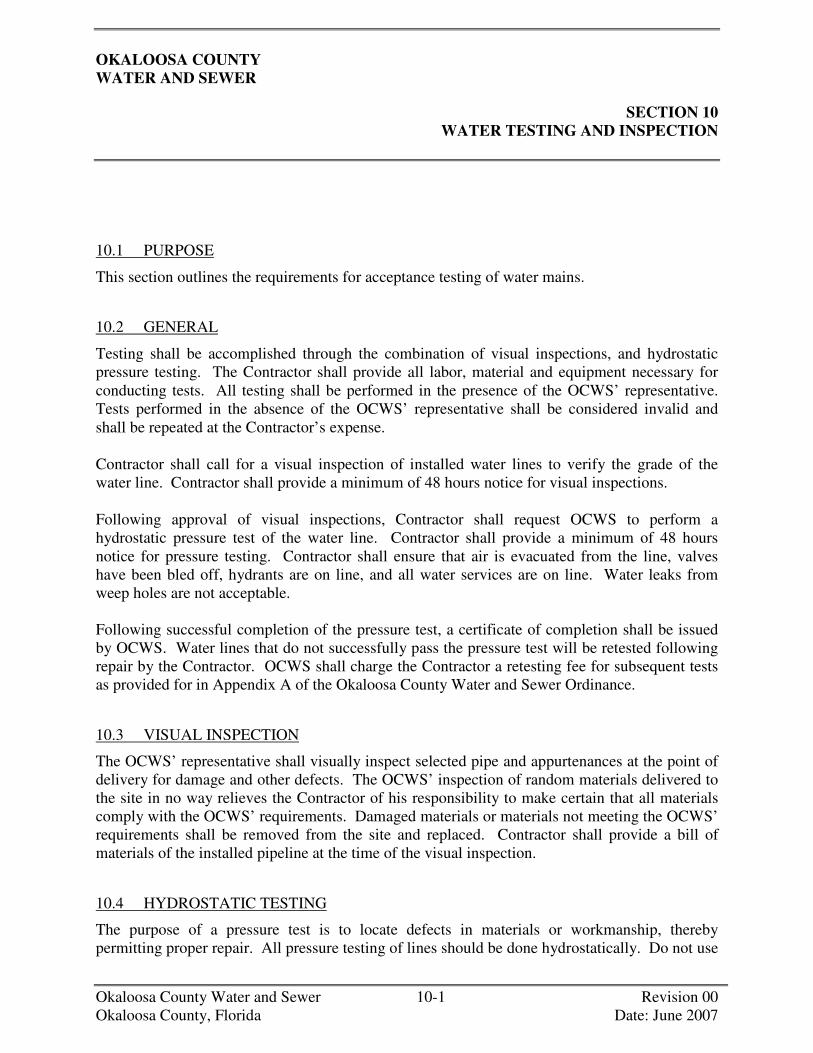
OKALOOSA COUNTY WATER AND SEWER
SECTION 10 WATER TESTING AND INSPECTION
Okaloosa County Water and Sewer 10-1 Revision 00 Okaloosa County, Florida Date: June 2007
10.1 PURPOSE
This section outlines the requirements for acceptance testing of water mains.
10.2 GENERAL
Testing shall be accomplished through the combination of visual inspections, and hydrostatic pressure testing. The Contractor shall provide all labor, material and equipment necessary for conducting tests. All testing shall be performed in the presence of the OCWS’ representative. Tests performed in the absence of the OCWS’ representative shall be considered invalid and shall be repeated at the Contractor’s expense. Contractor shall call for a visual inspection of installed water lines to verify the grade of the water line. Contractor shall provide a minimum of 48 hours notice for visual inspections. Following approval of visual inspections, Contractor shall request OCWS to perform a hydrostatic pressure test of the water line. Contractor shall provide a minimum of 48 hours notice for pressure testing. Contractor shall ensure that air is evacuated from the line, valves have been bled off, hydrants are on line, and all water services are on line. Water leaks from weep holes are not acceptable. Following successful completion of the pressure test, a certificate of completion shall be issued by OCWS. Water lines that do not successfully pass the pressure test will be retested following repair by the Contractor. OCWS shall charge the Contractor a retesting fee for subsequent tests as provided for in Appendix A of the Okaloosa County Water and Sewer Ordinance.
10.3 VISUAL INSPECTION
The OCWS’ representative shall visually inspect selected pipe and appurtenances at the point of delivery for damage and other defects. The OCWS’ inspection of random materials delivered to the site in no way relieves the Contractor of his responsibility to make certain that all materials comply with the OCWS’ requirements. Damaged materials or materials not meeting the OCWS’ requirements shall be removed from the site and replaced. Contractor shall provide a bill of materials of the installed pipeline at the time of the visual inspection.
10.4 HYDROSTATIC TESTING
The purpose of a pressure test is to locate defects in materials or workmanship, thereby permitting proper repair. All pressure testing of lines should be done hydrostatically. Do not use

STANDARD SPECIFICATIONS AND DESIGN MANUAL
air pressure to test water lines. THE USE OF AIR TO PRESSURE TEST A LINE, OR THE FAILURE TO REMOVE ALL AIR FROM A LINE PRIOR TO TESTING, CAN CAUSE EXPLOSIVE PRESSURES TO BUILD UP IN THE LINE CAUSING SERIOUS PERSONAL INJURY.
10.4.1 PRESSURE TEST RESTRICTIONS
The following restrictions shall be adhered to: • Test pressure shall not be less than 1.50 times the working pressure at the lowest
point along the test section, but not less than 150 psi. • Test pressures shall not exceed pipe or thrust-restraint design pressures. • Hydrostatic tests shall be of at least 2 hour duration. • The test pressure shall not exceed the rated pressure of the valves when the pressure
boundary of the test section includes closed, resilient-seated gate valves: Note: Resilient wedge gate valves approved by OCWS typically have a working pressure limit of 200 psig while resilient wedge gate valves incorporated with large backflow devices have a working pressure limit of 175 psig.
The following items must be considered prior to testing: • The pipe to be tested must be sufficiently backfilled (partial backfill) to prevent
movement while under pressure. • Joint restraint at fittings should be permanent and constructed to withstand test
pressure. If concrete thrust blocks are used, sufficient time must be allowed before testing to permit the concrete to cure. Cure time of seven days is recommended when Type I Portland Cement is used; three days is recommended when Type III Portland Cement is used.
• Test ends should be restrained to withstand the applicable thrusts that are developed under the test pressure.
10.4.2 AIR TESTING OF TAPPING SLEEVE
The OCWS maintenance staff will air test each tapping sleeve installed to ninety (90) psig for a period of 10 minutes. No pressure drop will be allowed. Successful testing of sleeve shall not relieve the Contractor of any leaks that may occur during the warranty period. At the Contractor's expense, the Board will repair all leaks that occur in the warranty period.
10.4.3 HYDROSTATIC TEST PROCEDURE
Construction of all service lines, fire hydrants and any/all other connections involving restrained joints and/or thrust blocking shall have been completed and inspected prior to scheduling of hydrostatic pressure test. Testing shall be in accordance with AWWA C600 hydrostatic pressure test scheduled with OCWS’ representative with a minimum of two (2) working days in advance. OCWS’ representative must be on site while flushing and testing is being performed.

WATER TESTING AND INSPECTION
Okaloosa County Water and Sewer 10-3 Revision 00 Okaloosa County, Florida Date: June 2007
10.4.3.1 Flushing
Foreign material left in the pipeline during installation often results in valve or hydrant seat leakage during pressure testing. Every effort should be made to keep lines clean during installation. Flushing shall be accomplished by partially opening and closing valves and hydrants several times under expected line pressure with adequate flow velocities to flush foreign materials out of the valves and hydrants. Mains shall be flushed to achieve a velocity of not less than 2 ft/second.
10.4.3.2 Filling the Line
The main should be filled slowly from OCWS' approved source of potable water. The water may be introduced from lines in service through valved connections, or by temporary connections to hydrants, or by taps made at the connection cap. All such connections, however, should be made at the lowest point in the line whenever possible.
10.4.3.3 Expelling Air from Pipe Line
Compressed entrapped air can greatly amplify any surges was well as pumping pressures. Furthermore, entrapped air can cause erroneous pressure test results. ALL air should be expelled from the pipeline during filling and again before making either pressure or leakage tests. Automatic air release valves located at high points are recommended for extended sections of new water main. If permanent air vents are not present at the high points, the Contractor may use corporation cocks at these points to expel the air as the line is filled with water. After the air has been expelled, the corporation cocks shall be closed and the test pressure applied. At the conclusion of the pressure test, the corporation cock shall be removed and the pipe plugged or left in place. It will be left to the Board's representative to determine if flushing alone (without the use of air vents or corporation stops) is sufficient to expel the entrapped air from the main.
10.4.3.4 Pressure Testing
All valves not required to be closed for isolation of the new main being tested shall be open during the testing including fire hydrant valves. The line shall be pumped up to no less than 150 psig and no more than 200. Once the pressure equalizes the line shall hold said pressure for a minimum of two hours. If line is not holding specified pressure at time of arrival of OCWS’ reprehensive, the test will be cancelled and rescheduled at the convenience of OCWS. This shall be repeated until the test requirements are satisfactory.
10.4.3.5 Flow Test
A minimum of 23 gpm shall be provided at each service.
10.4.3.6 Examination
The Contractor shall examine all exposed pipe, fittings, valves, hydrants, thrust blocks, restraints, and joints during the course of the hydrostatic testing. Any

STANDARD SPECIFICATIONS AND DESIGN MANUAL
damaged or defective work or material shall be repaired or replaced, and the test shall be repeated until satisfactory results are obtained.
10.5 DISINFECTION AND BACTERIOLOGICAL TESTING
Upon successful passing of the pressure test, the main(s) shall be disinfected by the Contractor who shall coordinate his testing with OCWS. The Contractor shall perform bacteriological testing of water mains. If such samples do not demonstrate satisfactory results, re-chlorination will be required. All service connections shall be made before testing and shall also be disinfected. The Contractor shall be responsible for the cost of chlorination during construction and testing.
10.6 FINAL INSPECTION
For the final inspection before acceptance by OCWS, all valve boxes shall be plumb and to grade, and curb stops shall be adjusted to the proper elevations (see standard drawing). OCWS' representative will check each valve to verify the valve is in the open position. Each curb stop shall be opened and closed. By-pass valves on meters shall be in the "closed" position. Adjustment of the by-pass valve after final inspection is prohibited. Upon completion of the project, OCWS' inspector shall verify that all valves are in the "open" position with the sole exception of the by-pass valve on larger meters. By-pass valves on large meters shall be in the "closed" position.
10.7 TEST FAILURE
Should a line fail to pass any of the acceptance tests as outlined, the Contractor shall, at his expense, determine the source of the failure, make any necessary repairs, and contact OCWS to re-test the segment of piping in question.
10.8 PRESSURE TEST EQUIPMENT
Equipment systems used to perform water pressure test shall be specifically designed for this purpose. The continuous monitoring pressure gage shall be liquid filled (glycerine) having a pressure range from 0 psig with minimum divisions of 5 psig. The gage face shall be a minimum of 4 inches in diameter and have an accuracy of ± .04 psig. The gauge shall meet or exceed Grade B ANSI-ASME B40.1.
+++ END OF SECTION +++
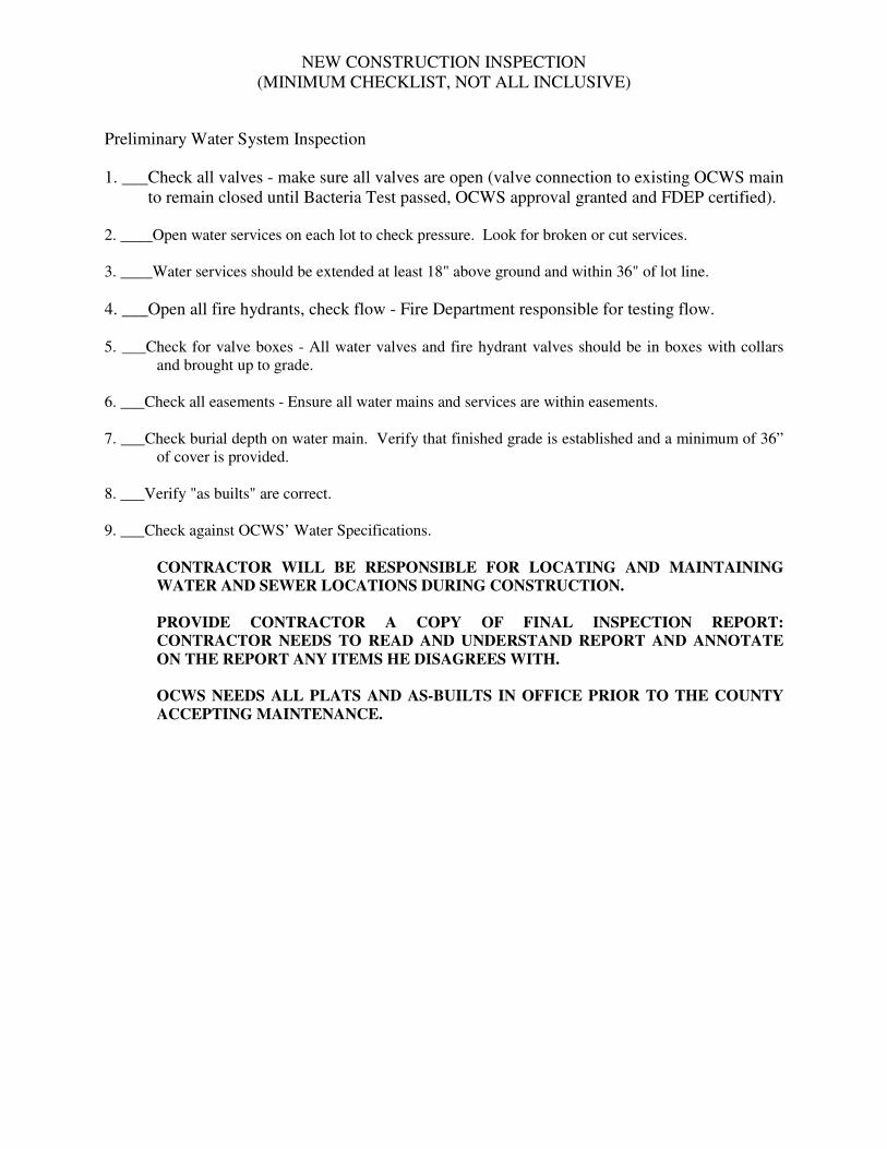
NEW CONSTRUCTION INSPECTION (MINIMUM CHECKLIST, NOT ALL INCLUSIVE)
Preliminary Water System Inspection 1. ___Check all valves - make sure all valves are open (valve connection to existing OCWS main
to remain closed until Bacteria Test passed, OCWS approval granted and FDEP certified). 2. ____Open water services on each lot to check pressure. Look for broken or cut services. 3. ____Water services should be extended at least 18" above ground and within 36" of lot line. 4. ___Open all fire hydrants, check flow - Fire Department responsible for testing flow. 5. ___Check for valve boxes - All water valves and fire hydrant valves should be in boxes with collars
and brought up to grade. 6. ___Check all easements - Ensure all water mains and services are within easements. 7. ___Check burial depth on water main. Verify that finished grade is established and a minimum of 36”
of cover is provided. 8. ___Verify "as builts" are correct. 9. ___Check against OCWS’ Water Specifications.
CONTRACTOR WILL BE RESPONSIBLE FOR LOCATING AND MAINTAINING WATER AND SEWER LOCATIONS DURING CONSTRUCTION. PROVIDE CONTRACTOR A COPY OF FINAL INSPECTION REPORT: CONTRACTOR NEEDS TO READ AND UNDERSTAND REPORT AND ANNOTATE ON THE REPORT ANY ITEMS HE DISAGREES WITH. OCWS NEEDS ALL PLATS AND AS-BUILTS IN OFFICE PRIOR TO THE COUNTY ACCEPTING MAINTENANCE.

NEW CONSTRUCTION INSPECTION (MINIMUM CHECKLIST, NOT ALL INCLUSIVE)
Preliminary Water System Inspection 1. ___Pressure test water main to not less than 150 PSI for 2 HRS with no more than 5 PSI drop in
pressure. If pressure drops more than 5 PSI in 2 HRS, conduct maximum allowable leakage test. 2. ____After 2 HRS pressure test: bleed pressure off; ensure all valves including fire hydrant valves are
open; if any valves were closed, rerun the pressure test. Preliminary Water System Inspection (After pressure test) 1 ____Check valves; make sure water mains are under pressure. 2. ____Check all water services; make sure tracer wire is installed and provides a continuous circuit. 3. ____Check all curb stops; should be locking curb stops. 4. ____Check water service taps; all taps should be 45° from vertical (taps made vertically will not be
accepted). 5. ____Open water services; make sure tap is open all the way. 6. ____Open fire hydrant(s) and check hydrant valves; check for valve boxes on hydrant(s). 7. ____Check fittings; for reinforcements around fittings, bends, hydrant, etc. 8. ____Check for tracer wire; should be 14 gauge on mains and services; should extend 18" above valve
box when uncoiled. 9. ____Make sure each lot has a service; service should be located on lot corner and should protrude at
least 18" above ground at the rear of the easement or right of way (at property line). 10. ___Fire hydrant(s) should be located on lot line with 4" pumper nozzle facing the road with at least
18" clearance above the ground. 11. ___Perform a rough check of cover over water main and proper location. 12. ___Turn water off until final inspection is complete - Inform Contractor water is off. 13. ___Get contact information:
Name: Address: 24 Hour Telephone Number: Office Number: FAX Number:
14. ___Check against OCWS’ Water Specification requirements.

SECTION 11
PUMP STATIONS


OKALOOSA COUNTY WATER AND SEWER
SECTION 11 TABLE OF CONTENTS
Okaloosa County Water and Sewer Revision 00 Okaloosa County, Florida Date: June 2007
SECTION 11 PUMP STATIONS 11.1 INTRODUCTION ...................................................................................................1 11.2 SERVICE AREA PLANNING................................................................................2 11.2.1 Establishing Service Area Boundaries.........................................................2 11.2.1.1 Physical Barriers and Topographic Limitations ........................2 11.2.1.2 Potential Wastewater Flow Rates ..............................................2 11.2.2 Projecting Service Area Wastewater Flows.................................................3 11.2.2.1 Service Area Data Collection.....................................................3 11.3 PUMP STATION DESIGN REQUIREMENTS .....................................................3 11.3.1 Introduction..................................................................................................3 11.3.2 Size Criteria .................................................................................................4 11.3.3 Wet Well ......................................................................................................4 11.3.4 Submersible Pumps......................................................................................4 11.3.5 Valve Pit.......................................................................................................4 11.3.6 Site Dimensions ...........................................................................................5 11.4 SUBMITTALS ........................................................................................................5 11.4.1 Submittal Items ............................................................................................5 11.5 GUIDELINE SPECIFICATIONS FOR CONSTRUCTION ..................................7 11.5.1 Valve Housing Box......................................................................................7 11.5.2 Wet Well ......................................................................................................7 11.5.2A Alternate West Well/Valve Box ................................................................8 11.5.3 Plates, Sheets, and Shapes ...........................................................................9 11.5.3.1 Aluminum Plates, Sheets, and Shapes .......................................9 11.5.3.2 Stainless Steel Plates, Sheets, and Shapes .................................9 11.5.3.3 Fastenings ................................................................................10 11.5.4 Submersible Pumping Equipment..............................................................10 11.5.4.1 Pumps.......................................................................................10 11.5.4.2 Manufacturing..........................................................................10 11.5.4.3 Submittal Data .........................................................................11 11.5.4.4 Pump Characteristics ...............................................................11 11.5.4.5 Controls....................................................................................11 11.5.4.6 Alternate Control Systems .......................................................12

STANDARD SPECIFICATIONS AND DESIGN MANUAL
Okaloosa County Water and Sewer Revision 00 Okaloosa County, Florida Date: June 2007
11.5.5 Electrical ....................................................................................................12 11.5.5.1 General .....................................................................................12 11.5.5.2 Materials ..................................................................................12 11.5.5.3 Installations ..............................................................................12 11.5.5.4 Stand-by Facilities ...................................................................13 11.5.5.5 Lightning Arrestor ...................................................................13 11.5.5.6 Main Disconnect ......................................................................13 11.5.6 General Requirements................................................................................13 11.5.6.1 As-Built Records......................................................................13 11.5.6.2 Nameplate ................................................................................13 11.5.6.3 Lubricants ................................................................................14 11.5.6.4 Operating Manuals and Parts Listed ........................................14 11.5.6.5 Telemetry Equipment...............................................................14 11.5.6.6 Fencing.....................................................................................14 11.5.6.7 Force Main (Thermoplastic Piping).........................................15 11.5.6.8 Water Service...........................................................................15

OKALOOSA COUNTY WATER AND SEWER
SECTION 11 PUMP STATIONS
Okaloosa County Water and Sewer 11-1 Revision 00 Okaloosa County, Florida Date: June 2007
11.1 INTRODUCTION
The purpose of this document is to present the OCWS’ guidelines and procedures regarding the planning, design, and construction of new wastewater pump stations in the OCWS’ service area. • Service area planning • Design Requirements • Design Flow Estimation • Peaking Factors • Wet Well Sizing Requirements • Controls • Control Room • Site Plans The service area planning procedures establish guidelines that developers must follow during the planning of proposed wastewater services for new developments. These procedures include: • A method for establishing the service area boundaries of the proposed wastewater facility • A procedure for performing wastewater flow rate projections using existing and projected
land use information and DEP requirements. The standard pump station design type presented in this document is limited to submersible pump stations that will serve new developing areas of the OCWS’ wastewater system. The average daily flow rate (ADF) capacities of the stations and gravity interceptors covered in this document are limited to a range of up to 1,000 gallons per minute (gpm). General specifications for materials and equipment are presented but are not intended to be used as construction specifications. Detailed construction specifications must be prepared by a professional engineer registered in the State of Florida. General pump station configurations and dimensions are presented for guidance and should be carefully reviewed to confirm that conflicts with specific equipment selection requirements do not exist. Dimensions presented in this document are intended to show relative sizing. Actual dimensions may vary and will depend on specific structural or foundation requirements of the proposed pump station. Equipment from specific manufacturers may require adjustments to the dimensions shown for proper installation.
THE DESIGN INFORMATION IN THIS REPORT SHOULD NOT BE CONSIDERED A PREDESIGN. THIS IS A GUIDANCE DOCUMENT TO USE IN PREDESIGN

STANDARD SPECIFICATIONS AND DESIGN MANUAL
Okaloosa County Water and Sewer 11-2 Revision 00 Okaloosa County, Florida Date: June 2007
PREPARATION. ALL DRAWINGS AND SPECIFICATIONS ARE PRESENTED FOR CONFORMANCE GUIDANCE AND NOT FOR USE IN CONSTRUCTION.
11.2 SERVICE AREA PLANNING
In order to plan properly for wastewater service, two important tasks must be completed by the initial developer: • Establish service area boundaries • Project the ultimate 20-year wastewater ADF for the service area
11.2.1 ESTABLISHING SERVICE AREA BOUNDARIES
The initial developer is responsible for determining the boundaries of the development area and for demonstrating how this area would best be served by a pump station. The initial developer will provide all the necessary supporting information and data to OCWS staff. The OCWS staff will review the initial developer’s planning documents to confirm that the proposed wastewater service area assumptions are acceptable.
The initial developer must consider the following criteria when determining the service area boundaries: • Physical barriers and topographic limitations that prelude the use of gravity
interceptors • The potential wastewater flow rate from future developments in the service area The importance of each of these criteria is discussed below.
11.2.1.1 Physical Barriers and Topographic Limitations
Physical barriers include major roadways, streambeds, high ridge points, and other obstacles that prevent the use of gravity interceptors. These types of barriers generally make cost effective service area boundaries. The general topography of the area is another factor to consider when establishing service area boundaries. Areas that have ground slopes in the range of 0.5 to 1.0 percent generally will provide adequate sanitary sewer pipe flow velocities at relatively shallow pipe burial depths. Ground slopes less than this generally require increased excavation (depth) to ensure adequate pipe slopes and flow velocities.
Because excavation depth increases with distance, this factor often determines the cost effectiveness of the pump station service areas boundaries. Pump station wet wells should not exceed a depth of 25 feet.
11.2.1.2 Potential Wastewater Flow Rates
The ultimate wastewater flows that will be conveyed by the interceptor or to the pump station from the areas being developed also must be considered when establishing boundaries. The design ADF of the submersible pump stations or interceptors considered in this manual must be less than 1,000 gpm. The maximum design flow limitation is required because service areas that produce

STANDARD SPECIFICATIONS AND DESIGN MANUAL
Okaloosa County Water and Sewer 11-3 Revision 00 Okaloosa County, Florida Date: June 2007
wastewater flows greater than 1,000 gpm generally will involve a more comprehensive planning effort than can be covered by this document.
The typical range of service area sizes to be considered in this document is less than 1,500 acres. This range is based upon the flow range up to 1,000 gpm and an average unit flow factor of 0.7 gpm per acre (discussed later in this section) and includes developments with an average of three single family dwellings per acre. The range decreases to 30 to 400 acres for high-density apartments or office complexes. If the physical barriers and topography indicate that an area greater than 1,500 acres can be serviced by a single pump station or interceptor, then a more comprehensive facilities planning study will be required to assess the need of a high-capacity regional pump station.
11.2.2 PROJECTING SERVICE AREA WASTEWATER FLOWS
Determining the projected wastewater flows for future growth within a service area is an essential factor when planning a pump station. This document presents a method to calculate the projected ultimate wastewater ADF based upon the type and size of the developments within the service area, unit wastewater flow factors, and the phasing of the developments.
11.2.2.1 Service Area Data Collection
The initial developer is responsible for estimating the projected ultimate wastewater ADF for his and other developer’s developments within the service area and for obtaining all necessary information about the type, size, and phasing of the developments proposed within a service area. This information must be obtained by contacting the other developers within the service area. Certified return receipt letters are required for this correspondence. The initial developer must describe to the other developers that application for the proposed pump station is being submitted and what impact it could have on them. The letters also must describe what information is requested from them and how this information will be used. Correspondence between the initial developer and the other developers must be documented and included in the wastewater service application submittal. If no response is received by the initial developer within a reasonable time, OCWS reserves the option of projecting whatever wastewater flow contribution it considers appropriate for the land parcel in question.
11.3 PUMP STATION DESIGN REQUIREMENTS
11.3.1 INTRODUCTION
This chapter presents a standard approach to the design of submersible pump stations with wastewater ADFs of up to 1,000 gpm. The sizing criteria and specifications for design and construction presented in this document are intended as guidelines for engineers and developers designing standard submersible pump stations for use in the OCWS’ wastewater system.

STANDARD SPECIFICATIONS AND DESIGN MANUAL
Okaloosa County Water and Sewer 11-4 Revision 00 Okaloosa County, Florida Date: June 2007
The standards presented in this chapter are based upon input from OCWS’ maintenance staff and on an inspection of the OCWS’ existing wastewater pump stations. OCWS’ maintenance personnel have had both positive and negative experiences with various pump station designs. As a result, they realize that certain design features can enhance or hinder the pump station’s ability to operate or the maintenance personnel’s ability to maintain these stations. Therefore, the design criteria presented in this document include design features to enhance the operation and maintenance of the OCWS’ future pump stations. Also, the use of standardized designs will help to ensure that stations designed by different engineers meet a minimum acceptable level of quality and require minimum operation and maintenance.
The OCWS will consider variations of the design standards presented in this document with proper documentation and review.
11.3.2 SIZE CRITERIA
The dimensions of the control room, wet well, valve pit, and the station site should be considered during the design of the pump station. Criteria for establishing the dimensions, as well as the importance of each of these components, are presented in the following sections. Criteria for establishing the capacity of the submersible pumps provided in the station are included also.
11.3.3 WET WELL
The wet well is a key component of a properly operating pump station. The dimensions of the wet well determine the frequency and duration of pump cycles, as well as the detention time of the wastewater at the station. As a result, a fixed volume of liquid must be retained and then pumped at a fixed rate, creating a cyclic pump operation. Presented below is a method for designing the minimum wet well volume for a submersible pump station.
11.3.4 SUBMERSIBLE PUMPS
In a duplex station, the submersible pumps shall be designed to operate at the PHF, and in a triplex station, two pumps operating in parallel shall be designed to have sufficient capacity to meet the PHF. The PHF can be calculated using PHF:ADF ratios. The minimum PHF:ADF ratio shall be 3.0 for pump stations designed based upon the criteria presented in this document. Consideration will be given to other PHF:ADF ratios only after a review, by OCWS staff, of supporting design information. Alternating LEAD/LAG pump control strategies shall be provided to control both duplex and triplex pump stations.
11.3.5 VALVE PIT
Clearance must be provided in the valve pit to allow for maintenance of the valves. The exact dimensions will be determined by discharge pipe size and specific valve assembly and disassembly clearances. The pit shall contain all check valves, gate valves, and
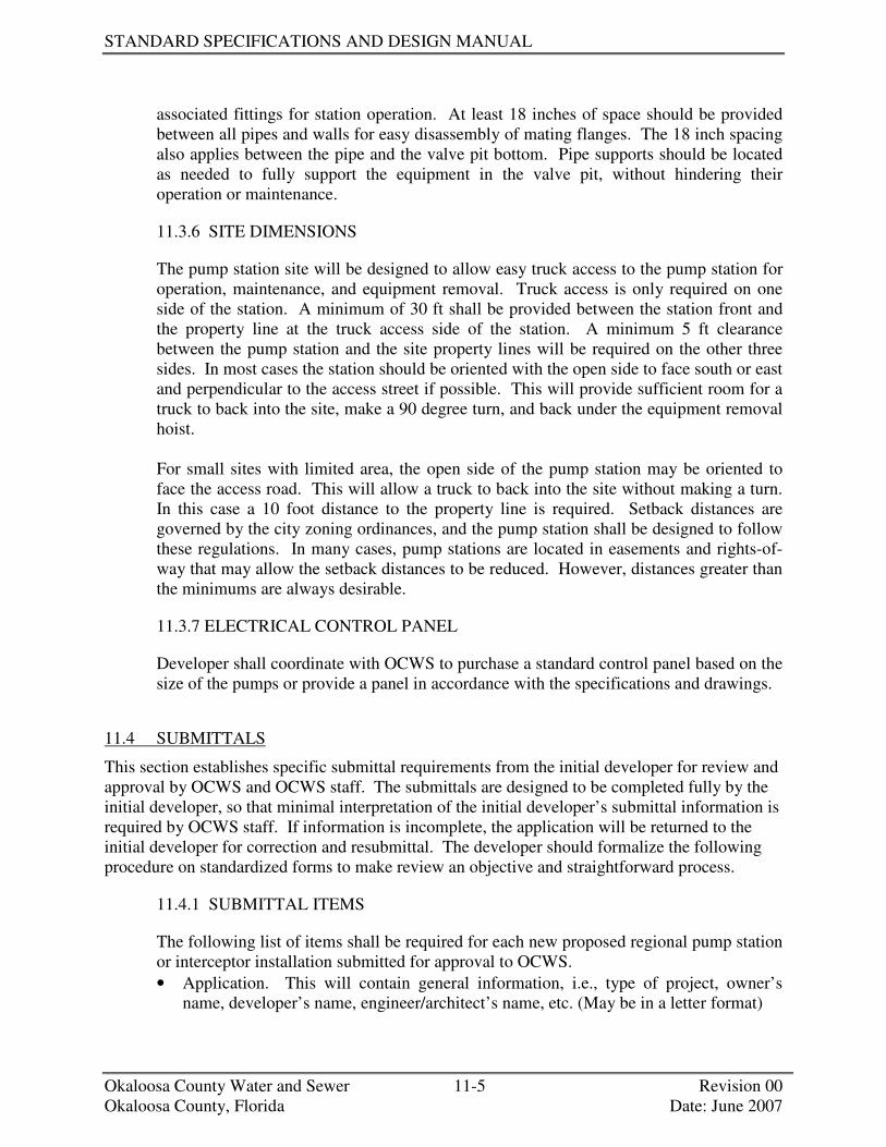
STANDARD SPECIFICATIONS AND DESIGN MANUAL
Okaloosa County Water and Sewer 11-5 Revision 00 Okaloosa County, Florida Date: June 2007
associated fittings for station operation. At least 18 inches of space should be provided between all pipes and walls for easy disassembly of mating flanges. The 18 inch spacing also applies between the pipe and the valve pit bottom. Pipe supports should be located as needed to fully support the equipment in the valve pit, without hindering their operation or maintenance.
11.3.6 SITE DIMENSIONS
The pump station site will be designed to allow easy truck access to the pump station for operation, maintenance, and equipment removal. Truck access is only required on one side of the station. A minimum of 30 ft shall be provided between the station front and the property line at the truck access side of the station. A minimum 5 ft clearance between the pump station and the site property lines will be required on the other three sides. In most cases the station should be oriented with the open side to face south or east and perpendicular to the access street if possible. This will provide sufficient room for a truck to back into the site, make a 90 degree turn, and back under the equipment removal hoist. For small sites with limited area, the open side of the pump station may be oriented to face the access road. This will allow a truck to back into the site without making a turn. In this case a 10 foot distance to the property line is required. Setback distances are governed by the city zoning ordinances, and the pump station shall be designed to follow these regulations. In many cases, pump stations are located in easements and rights-of-way that may allow the setback distances to be reduced. However, distances greater than the minimums are always desirable.
11.3.7 ELECTRICAL CONTROL PANEL
Developer shall coordinate with OCWS to purchase a standard control panel based on the size of the pumps or provide a panel in accordance with the specifications and drawings.
11.4 SUBMITTALS
This section establishes specific submittal requirements from the initial developer for review and approval by OCWS and OCWS staff. The submittals are designed to be completed fully by the initial developer, so that minimal interpretation of the initial developer’s submittal information is required by OCWS staff. If information is incomplete, the application will be returned to the initial developer for correction and resubmittal. The developer should formalize the following procedure on standardized forms to make review an objective and straightforward process.
11.4.1 SUBMITTAL ITEMS
The following list of items shall be required for each new proposed regional pump station or interceptor installation submitted for approval to OCWS. • Application. This will contain general information, i.e., type of project, owner’s
name, developer’s name, engineer/architect’s name, etc. (May be in a letter format)

STANDARD SPECIFICATIONS AND DESIGN MANUAL
Okaloosa County Water and Sewer 11-6 Revision 00 Okaloosa County, Florida Date: June 2007
• Request for Information Letters. Copies of the certified return receipt letters, return receipts, and any correspondence between the initial developer and other developers within the service area are to be included.
• Development Area Land Use Map. This map shall show land use planning using the WUFC classifications, presented in Table 3-2, of the initial developer’s development area. The scale range for the map shall be between 1” = 500’ and 1” = 100’.
• Flow Estimating Data Sheet. The data sheet shall contain the information presented in Table 4-1 of this document. Every development or parcel of land within the service area will be inventoried and included on this data sheet. The data sheet is completed by the initial developer for the development area and all future developments within the service area. The service area flows shall be estimated using the procedures presented in this document. Areas currently zoned agricultural and not likely to be rezoned within the planning period, as determined by the other developer, shall be included in the A-1 category for wastewater projection purposes.
• Service Area Land Use Map. This map shall include all land parcels within the service area. The service area shall include an area bounded by the practical limits for wastewater service using the guidelines given in the section titled “Establishing Service Area Boundaries.” OCWS staff shall be given a draft service area boundary to approve before completing the planning study and evaluation. The map shall include the following information: - List of all land parcels and current owners within the service area. - The proposed service area boundaries shall be identified. - All land parcels included within the service area boundaries, either in part or in
whole, shall be identified according to the list provided. Partial land parcels included in the service area limits should be included in the planning projection. These areas should be noted as partial inclusions on the planning map with both area inside and outside of the service area shown.
- Existing zoning district classifications used by the Okaloosa County Planning Division shall be indicated and the boundaries shown.
- Easily identifiable and legible elevation contours shall be shown. • Service Area Topographic Map. A topographic map of the service area shall include
the following information: - Contours at 5’ intervals - Streets, waterways, and drainage courses - Railroads - All other physical barriers - Limits of proposed development - Limits of final service area - Existing sanitary sewer system - Proposed location of new pump station - Proposed connection to existing system - All land parcels and their zoning classification The map scale range shall be between 1” = 500’ and 1” = 100’. Scales of 1” = 100’ are preferred.

STANDARD SPECIFICATIONS AND DESIGN MANUAL
Okaloosa County Water and Sewer 11-7 Revision 00 Okaloosa County, Florida Date: June 2007
11.5 GUIDELINE SPECIFICATIONS FOR CONSTRUCTION
The pump stations presented in this document shall be constructed to ensure long operational life with minimum operation and maintenance costs. The following section describes general conformance specifications for structural and architectural, mechanical, electrical and instrumentation, and geotechnical and civil disciplines.
11.5.1 VALVE HOUSING BOX
• The exterior of the valve housing box shall be water proofed by the manufacturer with two coats of Kopper’s Bitumastic 300-M pr approved equal type sealant to prevent ground water infiltration.
• The interior of the valve housing box shall have a smooth plastered finish, bottom section to be sloped to one corner.
• There shall be a minimum of 18 inches clearance on all sides of valves and fittings. • The check valves shall be a full body cast iron valve with external lever and spring as
manufactured by Empire Specialty Co. Inc., or approved equal. Cast Iron Body, renewable Buna N Seal, and AWWA C115 Flanged connection. The shaft, center pin, disc arm set screw, seat screws and disc arm key shall be stainless steel.
• All exposed hardware shall be of corrosion resistant, stainless steel. • The Access Hatches shall be aluminum double-door type, rated at 300 lb/sq. ft. A
minimum of 3' x 3' overall, mounted and centered on the box as shown on the drawings. Doors shall be of skid-proof design.
• All valve housing boxes shall be a solid cast in place or precast concrete box with bottom grouting of box bottom not permitted.
• The gate valves shall be AWWA C509 Compression Resilient Seated, Flanged Cast Iron Body with epoxy coated interior, and manual hand wheel actuator.
• An emergency by-pass gate valve with an Ever-tite Quick Coupling, Part "F", Female x Male iron pipe adaptor with male thread, 4" aluminum, shall be used, and installed within the valve box proceeding the in-line check and gate valve. The coupling should be located in a manner that it is accessible when the access hatch is open, with no obstructions so that a 4" suction hose can be easily attached for emergency operations.
11.5.2 WET WELL
• There shall be stainless steel pull chains fastened with stainless steel clamps to the lift rings on each pump. The stainless steel chain shall be of adequate strength to permit raising and lowering of the pumps.
• The entire internal discharge riser pipes shall be scheduled 80 P.V.C. joined with schedule 80 P.V.C. cement, or welded 304 stainless steel.
• A double door aluminum access frame and cover, rated at 300 lb/sq. ft., complete with hinged and flush locking mechanism, 316 S.S. upper guide holder and level sensor(s) cable holder shall be furnished and installed on the pump station wet well. Frame shall be securely placed, mounted above the pumps. Frame shall be provided with sliding nut rails to attach the accessories required. Lower guide bar holders shall be integral with the discharge connection. Guide bars shall be of at least 316 stainless

STANDARD SPECIFICATIONS AND DESIGN MANUAL
Okaloosa County Water and Sewer 11-8 Revision 00 Okaloosa County, Florida Date: June 2007
steel pipe. Doors shall be of skid proof design. • All lift eyes within the interior and exterior of wet well shall be cut off flush with the
existing surface, and sealed with a Bitumastic type sealant. • Steps will not be allowed inside the wet well. • Schedule 80 PVC with a flange on each end shall be used from the exterior of the wet
well into the valve box. • The discharge piping shall be intermediately supported inside the wet well by the use
of a stainless steel uni-strut bolted to the well wall, and stainless steel u-bolts and clamps secured to the discharge pipe and strut.
• All fasteners inside wet well shall be 316 stainless steel and coated with Never Sieze or equal.
• Hatch to wet well shall be as a minimum 4' x 4' in size or larger, as specified on plans. • All wet wells shall have an approved interior lining system. • Wet Well shall be 6' diameter or larger or 6' x 6' square or larger as specified on
plans. • A guide system for pump removal shall be installed inside the wet well for each
pump. The entire guide system shall be manufactured of a minimum 316 stainless steel and in accordance with the pump manufacture guidelines. All pipes for rail type guides shall have as a minimum, two (2) inches in diameter. The guide system shall not support any portion of the weight of the pump. The lower guide bracket shall be incorporated and tightly secured to the discharge connection elbow with 316 stainless steel fasteners. The entire guide system shall conform to Underwriters Laboratory (U. L.) requirements, for use in Class I, Division I, Group D environments.
• Influent piping shall be C-900 or C-905 PVC Pipe and be turned down to a level 6 inches below the lowest water level.
11.5.2. A ALTERNATE WET WELL/VALVE BOX
• Stand alone Fiberglass Structures may be used for Wet Well and Valve Pit. The FRP structures must meet and or exceed ASTM-D3753 standards. The structures must be Third Party Tested and Certified to meet the ASTM-D3753 standards. A copy of this certification must be provided with Submittal Data. Manufacturers that do not have this Third Party Certification included with the submittal data will not be approved. The structures must have labels that have serial numbers visible and states the manufacturer, date of manufacture, depth, diameter, and that structure meets ASTM-D3753 standards. If the Manufacturer is contacted they must be able to state purchaser, diameter, depth, and date that the wet well was purchased simply by providing the serial numbers. Manufacturers that do not maintain files that track serial numbers will not be accepted as warranties will not be verifiable.
• The fiberglass structures must have a standard 10 Year structural warranty. The fiberglass structures must have a printed 10 Year warranty label gel coated next to ASTM and serial number label. Copy of this warranty must be included with the submittal data. Approved Manufacturer is L.F. Manufacturing, Giddings, Texas (www.lfm-frp.com).
• Wet wells/Valve Pits shall have 12” risers with “Drop In” Aluminum Hatch Cover. Upon completion the wet well and valve pit shall have an 8” concrete slab poured

PUMP STATIONS
Okaloosa County Water and Sewer 11-9 Revision 00 Okaloosa County, Florida Date: June 2007
over top. On wet wells 8’ in diameter or larger an extra hatch cover shall be supplied on opposite side of wet well to allow installation of future equipment.
• The wet well shall include guide rail systems with SST components and fiberglass I-Beams or dual SST pipe for slide rails. The basis of design for the guide rail system is Hydromatic Pump’s Pultruded/MTM Rail System. The base elbow and sealing flange shall be constructed of Cast Iron.
• Valve pit shall include two (2) epoxy coated swing check valves with outside lever and spring, three (3) full port SST plug valves (By American), Emergency pump out connection with dust cap and all the necessary gaskets, straight pipe, brackets, elbows, tees, and fittings. Minimum valves and pipe size shall be 4”.
• All piping will be Sch. 40 SST for corrosion resistance and strength. Where piping passes through a wall sleeves shall be used with rubber link seals to make a watertight penetration. The sleeves must be large enough for flange of pipe being used to pass freely through (Example: 4” pipe would require a 10” sleeve to allow 9-1/2” O.D. diameter of 4” flange). The link seals are used so that the rubber acts as vibration isolator while pump is running.
• All piping in wet well and valve pit shall be welded Flange X Flange Sch. 40 SST. Hardware used for connections must be SST bolts with Brass nuts.
• Discharge piping in wet well must have “air release” valves (Waterman type, or equal).
• Oil filled pressure gauges rated for 1-1/2 times specified pumping pressures with ¾” SST ball valves must be provided for each discharge. Gauges must be located between check and plug valve so that static head can be observed when pump is off, TDH can be observed while pumps are running, and plug valves can be shut to observe “dead head” pressure.
• The Emergency Pump Out Connection Dust Cap must be tapped with ¼” pet cock so as to bleed off any accumulated pressure that may build up prior to removing cap.
11.5.3 PLATES, SHEETS, AND SHAPES
11.5.3.1 Aluminum Plates, Sheets and Shapes
All aluminum plates and shapes shall be of type AA 5052 alloy conforming to applicable requirements of ASTM Designation B 209-67, (latest revision). Aluminum extended shapes shall be 6061 or 6062 alloy conforming to ASTM B 221-67, (latest revision). All surfaces in contact with concrete shall be coated with Bitumastic (Kopper's 50 or equal).
11.5.3.2 Stainless Steel Plates, Sheets, and Shapes
All stainless steel plates and sheets shall be type 316 alloy conforming to the applicable requirements of ASTM Designation A-182, (latest revision). Stainless Steel pipe shall be schedule 5, Type 316 alloy conforming to the applicable requirements of ASTM-312, (latest revision).

STANDARD SPECIFICATIONS AND DESIGN MANUAL
Okaloosa County Water and Sewer 11-10 Revision 00 Okaloosa County, Florida Date: June 2007
11.5.3.3 Fastenings
Fasteners insofar as practical shall be concealed. Where exposed, fastening shall be of 316 stainless steel, where not indicated otherwise and countersunk wherever possible. All fastenings coming into contact with aluminum and /or submerged shall be of stainless steel. All hardware used to assemble ductile iron fittings shall be stainless steel. Threads shall be coated with antiseize compound. All threaded fasteners to include threaded rods shall be coated with antiseize compound.
11.5.4 SUBMERSIBLE PUMPING EQUIPMENT
11.5.4.1 Pumps
Pumps shall be submersible, heavy duty, recessed impeller type or an approved equal by the Okaloosa County Water & Sewer Engineering Department. The pumps shall be capable of handling raw, unscreened sewage. The discharge connection elbow shall be permanently installed in the wet well along with the discharge piping. The pumps shall be automatically connected to the discharge connection elbow when lowered into place, and shall be easily removed for inspection or service. There shall be no need for personnel to enter pump well. Sealing of the pumping unit to the discharge connection elbow shall be accomplished by the simple linear downward force of the pump. A sliding guide bracket shall be an integral part of the pump unit. The entire weight of the pump unit shall be guided by no less than two guide bars and pressed tightly against the discharge connection elbow with metal-to-metal contact by gravity only. Sealing of the discharge interface by means of a diaphragm, O-ring, or other devices will not be acceptable. No portion of the pump shall bear directly on the floor of the wet well. The pump, with its appurtenances and cable, shall be capable of continuous submergence underwater, without loss of water-tight integrity to a depth of 65 ft. Totally submersible design, with all electrical parts housed in an air-filled cast-iron, water tight enclosure. Thrust and radial bearings shall be of the ball type, the motor shafting shall be stainless steel and designed for extremely difficult sewage pumping service. The motors (less than 20 hp) shall be designed to operate on 3-phase, 60-cycle, 240/volt alternating current, and motors (greater than or equal to 20 hp) shall be designed to operate on 3-phase, 60-cycle, 480 volt alternating current, and each shall be non-overloading at all points on the pump curve. Alternate voltages may be considered by OCWS on a case by case basis.
11.5.4.2 Manufacturing
• Design HP of 25 or less: The duplex submersible pumps shall be as manufactured by ESSCO, Wemco, Hydromatic, or KSB. Submittal data must be reviewed and approved by Okaloosa County Water and Sewer Engineering

PUMP STATIONS
Okaloosa County Water and Sewer 11-11 Revision 00 Okaloosa County, Florida Date: June 2007
prior to final approval and purchase. • Design HP greater than 25: Pump selection for applications exceeding a
design horse power of 25 HP, shall be at the discretion and approval of Okaloosa County Water & Sewer Engineering, prior to approval of design. Submittal data must be reviewed and approved by Okaloosa County Water and Sewer Engineering prior to final approval and purchase.
11.5.4.3 Submittal Data
The contractor shall provide three (3) copies of the following submittal data for each item of pumping equipment: • Certified Dimensional Print • Typical Performance Curve • Pictorial and Schematic Wiring Prints • Parts Listed and Instructional Prints • Pump Components and Warranty
11.5.4.4 Pump Characteristics
Pumps shall furnish the following: • Pump to pass minimum sphere of 3 1/2 inch diameter. • Minimum motor size, 5 HP, unless otherwise approved by OCWS. • Recessed impellar unless otherwise approved by the OCWS Engineering
Department.
11.5.4.5 Controls
Automatic control of the duplex submersible pumps shall be by means of a system of float switches or compressed air. The switch shall by capable of starting and stopping the pumps at an adjustable differential, starting the lead pump first and then the lag pump if wet well level continues to rise, running both pumps simultaneously and automatic alternation of the lead and lag pumps. The control shall be housed in a Stainless Steel NEMA Standard 250, Type 4x enclosure with a pad lock hasp and handle. The enclosure shall include: • Dead front enclosure made of stainless steel. • Two (2) motor starters of adequate size. • 120-Volt, 20-Amp duplex receptacle. • Four (4) circuit breakers, one for each pump, one for the receptacle and one
for the control circuitry. • Two (2) HOA (hand-off automatic) switches. • Three (3) pole overload relay with one (1) heater per pole for each pump. • Pump alternating circuit. • 120 Volt AC Control Voltage. • Two (2) run lights (green), run light shall be clearly labeled. • Two (2) moisture detection relays and yellow warning lights. • Two (2) 0 to 99,999.9 hour elapsed time meters. • Phase Failure relay required (plug-in type, 8-pin).
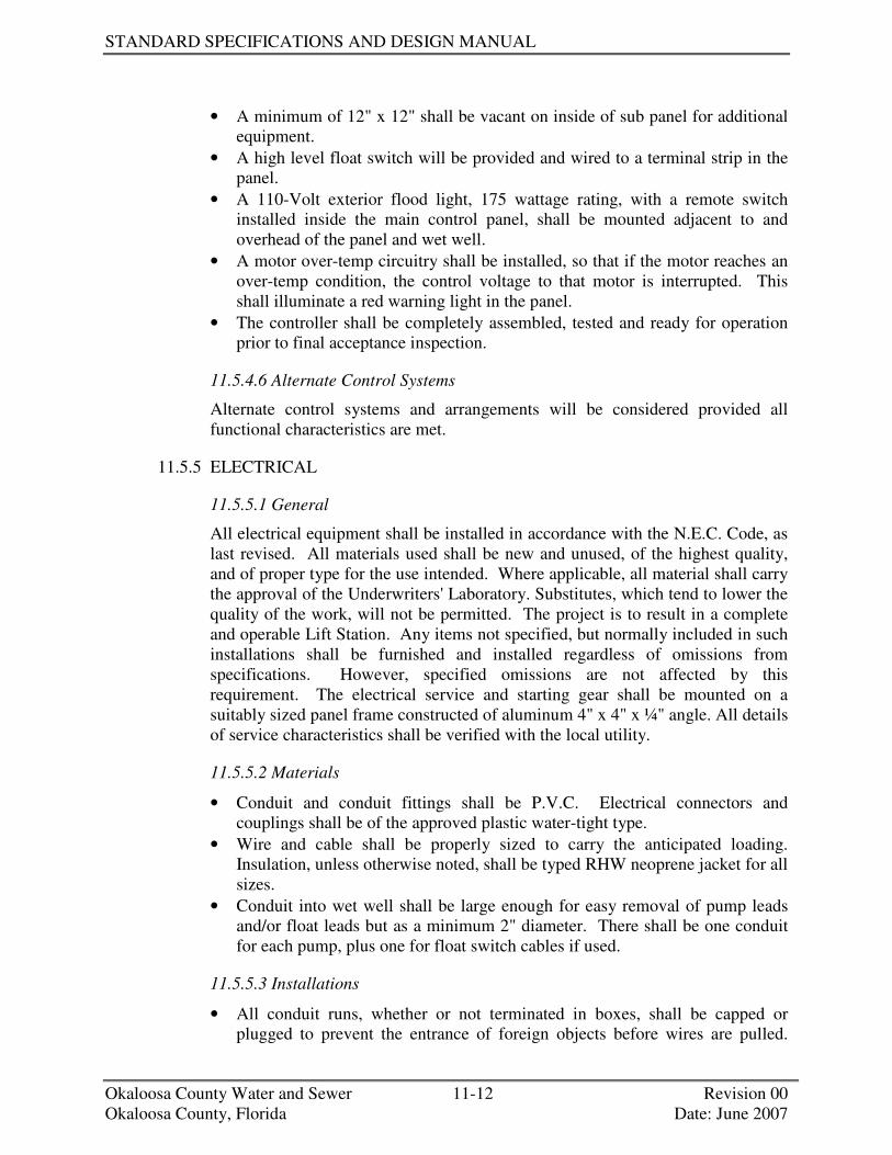
STANDARD SPECIFICATIONS AND DESIGN MANUAL
Okaloosa County Water and Sewer 11-12 Revision 00 Okaloosa County, Florida Date: June 2007
• A minimum of 12" x 12" shall be vacant on inside of sub panel for additional equipment.
• A high level float switch will be provided and wired to a terminal strip in the panel.
• A 110-Volt exterior flood light, 175 wattage rating, with a remote switch installed inside the main control panel, shall be mounted adjacent to and overhead of the panel and wet well.
• A motor over-temp circuitry shall be installed, so that if the motor reaches an over-temp condition, the control voltage to that motor is interrupted. This shall illuminate a red warning light in the panel.
• The controller shall be completely assembled, tested and ready for operation prior to final acceptance inspection.
11.5.4.6 Alternate Control Systems
Alternate control systems and arrangements will be considered provided all functional characteristics are met.
11.5.5 ELECTRICAL
11.5.5.1 General
All electrical equipment shall be installed in accordance with the N.E.C. Code, as last revised. All materials used shall be new and unused, of the highest quality, and of proper type for the use intended. Where applicable, all material shall carry the approval of the Underwriters' Laboratory. Substitutes, which tend to lower the quality of the work, will not be permitted. The project is to result in a complete and operable Lift Station. Any items not specified, but normally included in such installations shall be furnished and installed regardless of omissions from specifications. However, specified omissions are not affected by this requirement. The electrical service and starting gear shall be mounted on a suitably sized panel frame constructed of aluminum 4" x 4" x ¼" angle. All details of service characteristics shall be verified with the local utility.
11.5.5.2 Materials
• Conduit and conduit fittings shall be P.V.C. Electrical connectors and couplings shall be of the approved plastic water-tight type.
• Wire and cable shall be properly sized to carry the anticipated loading. Insulation, unless otherwise noted, shall be typed RHW neoprene jacket for all sizes.
• Conduit into wet well shall be large enough for easy removal of pump leads and/or float leads but as a minimum 2" diameter. There shall be one conduit for each pump, plus one for float switch cables if used.
11.5.5.3 Installations
• All conduit runs, whether or not terminated in boxes, shall be capped or plugged to prevent the entrance of foreign objects before wires are pulled.

PUMP STATIONS
Okaloosa County Water and Sewer 11-13 Revision 00 Okaloosa County, Florida Date: June 2007
Conduit projecting into the wet well shall be plugged to a depth no more than 2" from the control panel with non-hardening compound, after the wires are pulled to prevent corrosive gases from reaching the control panel. Compound should be easily removed for removal\replacement of wiring.
• Outlets, switches, boxes, etc., shall be rigidly secured and located properly with respect to easy accessibility.
• No electrical splices allowed except in control panel. • All work shall be tested and subject to final approval of the engineer.
11.5.5.4 Stand-by Facilities
A double throw safety switch suitable sized to carry the operating current of the station with attached emergency generator receptacle shall be installed between the main disconnect and the controller. The unit shall be housed in a NEMA 3R stainless steel enclosure. The receptacle shall be a Crouse-Hinds, rated for 100-Amp minimum, larger as required. A 45 degree angle adapter is recommended to allow for easier generator connection, and to prevent water intrusion.
11.5.5.5 Lightning Arrestor
The lightning arrestor for the main service entrance shall be Joshlin or approved equal.
11.5.5.6 Main Disconnect
The main disconnect safety switch shall be a fused, enclosed service entrance, weather-proof enclosure, 4 wire S/N, 240/480 Volt AC of sufficient size to carry all pumps operating simultaneously.
11.5.6 GENERAL REQUIREMENTS
11.5.6.1 As-Built Records
A complete set of As-Built records shall be kept by the Contractor. These records shall show all items of construction and equipment which differ in size, shape or location from those shown on the contract drawings, also any additional work, existing features or utilities revealed by construction work which are not shown on the contract drawings. These reports shall be kept up-to-date daily. They may be kept on a marked set of contract drawings to be furnished by the contractor for this purpose, or in any other form, which is approved prior to the beginning of the work. They shall be available at all times during construction for reference by the Engineer and Owner, and shall be delivered to the OCWS Engineering Department upon completion of the work.
11.5.6.2 Nameplate
Each piece of mechanical equipment and motors shall be provided with a substantial nameplate of non-corrodible metal securely fastened in place, and clearly and permanently inscribed with the manufacturer's name, model, or type designation, serial number, rated capacity, electrical or other power

STANDARD SPECIFICATIONS AND DESIGN MANUAL
Okaloosa County Water and Sewer 11-14 Revision 00 Okaloosa County, Florida Date: June 2007
characteristics, and other appropriate nameplate data. Spare nameplates shall be provided for each lift station and placed inside each control panel (one nameplate for each model pump).
11.5.6.3 Lubricants
All the equipment shall be delivered fully lubricated with oil and/or grease insofar as possible. If any point cannot be so serviced, it shall be clearly marked to the effect that it is not lubricated and requires servicing prior to operation. An adequate supply of the proper lubricant, with the instructions for its application shall be supplied with the equipment for each point not lubricated prior to shipment. The Contractor shall also provide the Owner with a sufficient amount of proper lubricants for one complete change of lubricant for all equipment furnished.
11.5.6.4 Operating Manuals and Parts Listed
The Contractor shall furnish three (3) complete, bound sets of literature giving the following information to the Okaloosa County Water and Sewer Engineering Department. • Clear and Concise instruction for operations, adjustment and lubrication and
other of the equipment. These instructions shall include a complete lubrication chart.
• A list of all parts of the equipment, with catalog number and other data necessary for ordering replacement parts.
• Such instructions and parts listed shall have been prepared specifically for the model and type of equipment furnished and shall not refer to other models and types of similar equipment.
• Complete sets of electrical schematic(s), (as built) one of which shall be encapsulated in plastic and permanently mounted to the inside of the liftstation door.
11.5.6.5 Telemetry Equipment
A telemetry fee shall be paid to: Okaloosa County Water and Sewer System 1804 Lewis Turner Boulevard, Suite 300 Fort Walton Beach, Florida 32547
This fee will cover the expense of installing telemetry equipment, at the time of purchasing other associated connection cost.
11.5.6.6 Fencing
Fence specifications will vary, subject to the requirements of the developer and the Okaloosa County Water and Sewer System.

PUMP STATIONS
Okaloosa County Water and Sewer 11-15 Revision 00 Okaloosa County, Florida Date: June 2007
11.5.6.7 Force Main (Thermoplastic piping)
A #14 copper insulated tracer wire shall be laid over the full length of the force main.
11.5.6.8 Water Service
A ¾" Potable water service with backflow preventor shall be made available at Lift Station Site.
+++ END OF SECTION +++


SECTION 12
VARIANCES

OKALOOSA COUNTY WATER AND SEWER
SECTION 12 VARIANCES
Okaloosa County Water and Sewer Revision 00 Okaloosa County, Florida Date: June 2007
SECTION 12 VARIANCES 12.1 PURPOSE................................................................................................................1 12.2 GENERAL ..............................................................................................................1


OKALOOSA COUNTY WATER AND SEWER
SECTION 12 VARIANCES
Okaloosa County Water and Sewer Revision 00 Okaloosa County, Florida Date: June 2007
12.1 PURPOSE
The purpose of this section is to provide guidelines for any deviations deemed necessary to the standard specifications and design manual.
12.2 GENERAL
If any deviations to the design standards are deemed necessary due some unique characteristics of the project topography, etc, written justification must be submitted to the Director of OCWS and written approval of the deviation obtained prior to any construction.
+++ END OF SECTION +++


DIVISIONS


OKALOOSA COUNTY WATER AND SEWER
DIVISION 1
Okaloosa County Water and Sewer Revision 00 Okaloosa County, Florida Date: June 2007
DIVISION 1 GENERAL REQUIREMENTS
SECTION 01570 MAINTENANCE AND PROTECTION OF TRAFFIC SECTION 01710 CLEANING SECTION 01730 OPERATION AND MAINTENANCE DATA


Okaloosa County Water and Sewer 01570-1 Revision 00 Okaloosa County, Florida Date: June 2007
SECTION 01570
MAINTENANCE AND PROTECTION OF TRAFFIC
1.1 GENERAL
A. All streets and trafficways shall be kept open for the passage of traffic and pedestrians during the construction period unless otherwise approved by OCWS.
B. When required to cross, obstruct or temporarily close a street or trafficway, CONTRACTOR shall provide and maintain suitable bridges, detours or other approved temporary expedient for the accommodation of traffic. Closings shall be for the shortest time practical, and passage shall be restored immediately after completion of backfill and temporary paving or bridging.
C. CONTRACTOR shall give the required advance notice to the fire and police departments of his proposed operations.
D. CONTRACTOR shall give reasonable notice to owners or tenants of private property who may be affected by his operations.
E. CONTRACTOR shall provide signs, signals, barricades, flares, lights and all other equipment, service and personnel required to regulate and protect all traffic, and warn of hazards. All such work shall conform to requirements of the OWNER or OCWS having jurisdiction. Remove temporary equipment and facilities when no longer required, restore grounds to original, or to specified conditions.
1.2 TRAFFIC SIGNALS AND SIGNS
A. Provide and operate traffic control and directional signals required to direct and maintain an orderly flow of traffic in all areas under CONTRACTOR'S control, or affected by CONTRACTOR'S operations.
B. Provide traffic control and directional signs, mounted on barricades or standard posts: 1. At each change of direction of a roadway and at each crossroad. 2. At detours and hazardous areas. 3. At parking areas.
1.3 FLAGMEN
A. Provide qualified and suitably equipped flagmen when construction operations encroach on traffic lanes, as required for regulation of traffic and in accordance with the requirements of OCWS having jurisdiction.
1.4 FLARES AND LIGHTS
A. Provide flares and lights during periods of low visibility: 1. To clearly delineate traffic lanes, to guide traffic and to warn of hazardous
areas.

Okaloosa County Water and Sewer 01570-2 Revision 00 Okaloosa County, Florida Date: June 2007
2. For use by flagmen in directing traffic. B. Provide illumination of critical traffic and parking areas.
1.5 PARKING CONTROL
A. Control all CONTRACTOR related vehicular parking within the limits of the Work to preclude interference with public traffic or parking, access by emergency vehicles, OWNER'S operations, or construction operations. Provide temporary parking facilities for the public as may be required because of construction or operations.
B. Monitor parking of all construction and private vehicles: 1. Maintain free vehicular access to and through parking areas. 2. Prohibit parking on or adjacent to access roads, or in non-designated areas.
1.6 HAUL ROUTES
A. If extensive hauling is necessary, consult with governing authorities and establish thoroughfares, which will be used as haul routes and site access.
B. Confine construction traffic to designated haul routes. C. Provide traffic control at critical areas of haul routes to expedite traffic flow, to
minimize interference with normal public traffic.

Okaloosa County Water and Sewer 01710-1 Revision 00 Okaloosa County, Florida Date: June 2007
SECTION 01710
CLEANING
PART 1 - GENERAL
1.1 REQUIREMENTS OF REGULATORY AGENCIES
A. Conduct cleaning and waste-removal operations to comply with local laws and ordinances and Federal and local environmental and anti-pollution regulations.
1.2 PROGRESS CLEANING
A. General: Clean the Site, Work areas and other areas CONTRACTOR is permitted to occupy by Laws and Regulations at least weekly. Dispose of materials lawfully according to Laws and Regulations: 1. Comply with requirements in NFPA 241, Standard for Safeguarding
Construction, Alteration and Demolition Operations, for removal of combustible waste materials and debris.
2. Do not hold other materials more than 7 days during normal weather or 3 days if the temperature is expected to rise above 80 F.
3. Provide suitable containers for storage of waste materials and debris. 4. Containerize hazardous and unsanitary waste materials separately from
other waste. Mark containers appropriately. B. Project:
1. Maintain Project free of waste materials and debris. 2. Keep exterior dust generating areas wetted down.
C. Work Areas: Clean areas where Work is in progress to the level of cleanliness necessary for proper execution of the Work. 1. Remove liquid spills promptly. 2. Where dust would impair proper execution of the Work, broom-clean or
vacuum the entire Work area, as appropriate. D. Installed Work: Keep installed Work clean. Clean installed surfaces according to
written instructions of manufacturer or fabricator of product installed, using only cleaning materials specifically recommended. If specific cleaning materials are not recommended, use cleaning materials that are not hazardous to health or property and that will not damage exposed surfaces.
E. Concealed Spaces: Remove debris from concealed spaces before enclosing the space.
F. Exposed Surfaces: Clean exposed surfaces and protect as necessary to ensure freedom from damage and deterioration at time of Substantial Completion.
G. Cutting and Patching: Clean areas and spaces where cutting and patching are performed. Completely remove paint, mortar, oils, putty, and similar materials.

Okaloosa County Water and Sewer 01710-2 Revision 00 Okaloosa County, Florida Date: June 2007
1. Thoroughly clean piping, conduit, and similar features before applying paint or other finishing materials. Restore damaged pipe covering to its original condition.
H. Waste Disposal: Burying or burning waste materials on the Site will not be permitted. Washing waste materials down sewers or into waterways will not be permitted.
I. During handling and installation, clean and protect construction in progress and adjoining materials already in place. Apply protective covering where required to ensure protection from damage or deterioration at Substantial Completion.
J. Clean and provide maintenance on completed construction as frequently as necessary through the remainder of the construction period. Adjust and lubricate operable components to ensure operability without damaging effects.
1.3 FINAL CLEANING
A. General: Provide final cleaning. 1. Complete the following cleaning and waste-removal operations before
requesting inspection for certification of Substantial Completion for entire Project or for a portion of Project: a. Clean and remove from the Project rubbish, waste material, litter, and
other foreign substances. b. Sweep paved areas broom clean. Remove petrochemical spills, stains,
and other foreign deposits. c. Hose clean sidewalks and loading areas. d. Rake grounds that are neither planted nor paved to a smooth, even-
textured surface. e. Leave water courses, gutters, and ditches open and clean. f. Clean exposed exterior and interior hard-surfaced finishes to a dirt-free
condition, free of spatter, grease, stains, fingerprints, films, and similar foreign substances.
g. Remove debris and surface dust from limited access spaces, including roofs, plenums, shafts, trenches, equipment vaults, manholes, and similar spaces.
h. Remove tags and labels that are not permanent. i. Touch up and otherwise repair and restore chipped, scratched, dented
or otherwise marred surfaces to specified finish and match adjacent surfaces. 1) Do not paint over “UL” and similar labels, including mechanical
and electrical nameplates. j. Wipe surfaces of mechanical and electrical equipment, and similar
equipment. Remove excess lubrication, paint and mortar droppings, and other foreign substances.
k. Maintain the cleaning until OWNER occupies the Project or portion thereof.
l. Leave Project clean and in a neat and orderly condition satisfactory to OCWS.

Okaloosa County Water and Sewer 01710-3 Revision 00 Okaloosa County, Florida Date: June 2007
PART 2 - PRODUCTS (NOT USED)
PART 3 - EXECUTION (NOT USED)


Okaloosa County Water and Sewer 01730-1 Revision 00 Okaloosa County, Florida Date: June 2007
SECTION 01730
OPERATION AND MAINTENANCE DATA
PART 1 GENERAL
1.1 SCOPE
A. CONTRACTOR shall provide operation and maintenance data in the form of instructional manuals for use by the OWNER’S personnel for: 1. All equipment and systems. 2. All valves, gates and related accessories. 3. All instruments and control devices. 4. All electrical gear and equipment.
B. Each manual shall be prepared specially for the Project and shall include all pertinent instructions, as-built drawings, bills of materials, listings, technical bulletins, and other printed materials required to provide fully accurate and comprehensive information for the safe and proper operation, maintenance and repair of the equipment or system supplied for the Project. The manual shall include any specific information required by the applicable Specification Section. It also shall include all data that must accompany said manual as directed by current regulations of any participating government agency.
1.2 FORMAT
A. Each operation and maintenance manual shall be bound in a durable, permanent, stiff cover binder of one or more volumes. Binders shall be of the three-ring type or three post type and shall not be overfilled. Covers shall be oil, moisture and wear resistant.
B. The contents of the manual shall be printed on 8-1/2 by 11 inches 30 pound (minimum) paper and binding holes shall be reinforced with plastic, cloth or metal.
C. All contents shall be original quality copies. That is, the material shall either be original manufacturer printed or typed materials or xerographic copies that are indistinguishable from the original. Manuals that contain copies that are not clear, not completely legible, off-center, skewed, or where text or drawings are cut by the binding holes shall be subject to disapproval. Pages that contain approval or date stamps, comments, or other markings that cover any portion of text or drawing are unacceptable. Electronically transmitted facsimile (fax) copies are also unacceptable.
D. Drawings, diagrams and illustrations up to and including 11 by 17 inches in size shall be bound into the manual. Larger size documents shall be folded and inserted into clear plastic pockets or envelopes bound into the manual and marked as to contents.

Okaloosa County Water and Sewer 01730-2 Revision 00 Okaloosa County, Florida Date: June 2007
E. Manuals shall be organized into sections or categories of information such as operating instructions, preventive maintenance, drawings, and parts list. Use dividers and indexed tabs to separate sections.
F. Provide a table of contents indicating the title of each section and a complete listing of the contents of each section in the order of presentation within the section.
G. The manuals shall be identified by labels firmly attached to the front cover and the spine. Identify each binder with the following: 1. Title “OPERATING AND MAINTENANCE INSTRUCTIONS”. 2. Name or type of equipment or system manual concerns. 3. Identity of building or structure, as applicable. 4. Title of Project. 5. Volume number, if more than one.
1.3 CONTENTS
A. Provide complete, detailed written operating instructions for each product including: function; operating characteristics; limiting conditions; operating instructions for startup, normal and emergency conditions; regulation and control; operational troubleshooting; and shutdown. Also include, as applicable, written descriptions of any alarms generated by the product and the proper responses to such alarm conditions.
B. Include written explanations of all safety considerations relating to operation and maintenance procedures.
C. Provide complete, detailed written preventive maintenance instructions including all information and instructions to keep the product properly lubricated, adjusted and maintained so that the item functions economically throughout its full design life. These instructions shall include, but are not limited to the following: 1. Written explanations with illustrations for each preventive maintenance
task such as inspection, adjustment, lubrication, calibration and cleaning. Also provide pre-startup checklists for each piece of equipment and long-term shutdown maintenance requirements.
2. Recommended schedule for each preventive maintenance task. 3. Lubrication charts indicating recommended types of lubricants, frequency
of application or change, and where each are to be used or applied. 4. Table of alternative lubricants. 5. Troubleshooting instructions. 6. List of required maintenance tools and equipment.
D. Complete bills of material or parts lists for products provided. Lists or bills of material may be provided on a per drawing or per equipment assembly basis. The bills of material shall indicate: 1. The name, address and phone number of the manufacturer. 2. The name, address and phone number of the nearest manufacturer’s rep-
resentative, parts warehouse or parts supplier. 3. The manufacturer’s shop order and/or serial number(s) for the equipment
or assembly.
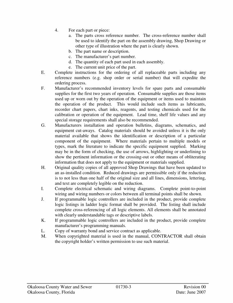
Okaloosa County Water and Sewer 01730-3 Revision 00 Okaloosa County, Florida Date: June 2007
4. For each part or piece: a. The parts cross reference number. The cross-reference number shall
be used to identify the part on the assembly drawing, Shop Drawing or other type of illustration where the part is clearly shown.
b. The part name or description. c. The manufacturer’s part number. d. The quantity of each part used in each assembly. e. The current unit price of the part.
E. Complete instructions for the ordering of all replaceable parts including any reference numbers (e.g. shop order or serial number) that will expedite the ordering process.
F. Manufacturer’s recommended inventory levels for spare parts and consumable supplies for the first two years of operation. Consumable supplies are those items used up or worn out by the operation of the equipment or items used to maintain the operation of the product. This would include such items as lubricants, recorder chart papers, chart inks, reagents, and testing chemicals used for the calibration or operation of the equipment. Lead time, shelf life values and any special storage requirements shall also be recommended.
G. Manufacturers installation and operation bulletins, diagrams, schematics, and equipment cut-aways. Catalog materials should be avoided unless it is the only material available that shows the identification or description of a particular component of the equipment. Where materials pertain to multiple models or types, mark the literature to indicate the specific equipment supplied. Marking may be in the form of checking, the use of arrows, highlighting or underlining to show the pertinent information or the crossing-out or other means of obliterating information that does not apply to the equipment or materials supplied.
H. Original quality copies of all approved Shop Drawings that have been updated to an as-installed condition. Reduced drawings are permissible only if the reduction is to not less than one half of the original size and all lines, dimensions, lettering, and text are completely legible on the reduction.
I. Complete electrical schematic and wiring diagrams. Complete point-to-point wiring and wiring numbers or colors between all terminal points shall be shown.
J. If programmable logic controllers are included in the product, provide complete logic listings in ladder logic format shall be provided. The listing shall include complete cross-referencing of all logic elements. All elements shall be annotated with clearly understandable tags or descriptive labels.
K. If programmable logic controllers are included in the product, provide complete manufacturer’s programming manuals.
L. Copy of warranty bond and service contract as applicable. M. When copyrighted material is used in the manual, CONTRACTOR shall obtain
the copyright holder’s written permission to use such material.
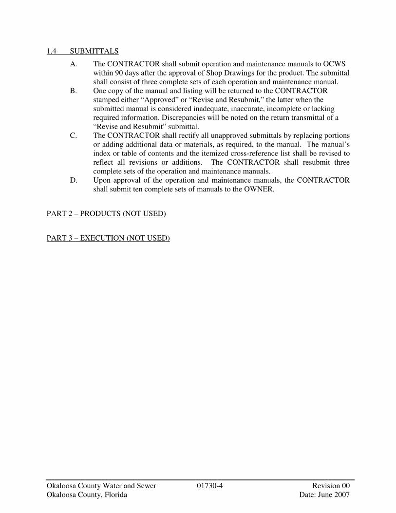
Okaloosa County Water and Sewer 01730-4 Revision 00 Okaloosa County, Florida Date: June 2007
1.4 SUBMITTALS
A. The CONTRACTOR shall submit operation and maintenance manuals to OCWS within 90 days after the approval of Shop Drawings for the product. The submittal shall consist of three complete sets of each operation and maintenance manual.
B. One copy of the manual and listing will be returned to the CONTRACTOR stamped either “Approved” or “Revise and Resubmit,” the latter when the submitted manual is considered inadequate, inaccurate, incomplete or lacking required information. Discrepancies will be noted on the return transmittal of a “Revise and Resubmit” submittal.
C. The CONTRACTOR shall rectify all unapproved submittals by replacing portions or adding additional data or materials, as required, to the manual. The manual’s index or table of contents and the itemized cross-reference list shall be revised to reflect all revisions or additions. The CONTRACTOR shall resubmit three complete sets of the operation and maintenance manuals.
D. Upon approval of the operation and maintenance manuals, the CONTRACTOR shall submit ten complete sets of manuals to the OWNER.
PART 2 – PRODUCTS (NOT USED)
PART 3 – EXECUTION (NOT USED)
OKALOOSA COUNTY WATER AND SEWER
DIVISION 2
Okaloosa County Water and Sewer Revision 00 Okaloosa County, Florida Date: June 2007
DIVISION 2 SITE CONSTRUCTION
SECTION 02110 CLEARING SECTION 02220 EXCAVATION AND BACKFILL SECTION 02512 BITUMINOUS PAVING SECTION 02606 MANHOLES


Okaloosa County Water and Sewer 02110-1 Revision 00 Okaloosa County, Florida Date: June 2007
SECTION 02110
CLEARING
PART 1 - GENERAL
1.1 DESCRIPTION
A. Scope: CONTRACTOR shall furnish all labor, materials, equipment and incidentals required to perform all clearing and grubbing as shown and specified.
B. Related Work Specified Elsewhere: 1. Section 01570, Maintenance and Protection of Traffic 2. Section 02512, Bituminous Paving 3. Section 02606, Manholes 4. Section 15051, Buried Piping Installation 5. Section 15052, Exposed Piping Installation 6. Section 15100, Valves, 4 Inch and Larger
1.2 QUALITY ASSURANCE
A. Codes and Standards: State and local laws and code requirements shall govern the hauling and disposal of trees, shrubs, stumps, roots, rubbish, debris and other matter.
1.3 JOB CONDITIONS
A. Protection: 1. Streets, roads, adjacent property and other works and structures shall be
protected throughout the entire project. CONTRACTOR shall return to original condition, satisfactory to OCWS, damaged facilities caused by the CONTRACTOR'S operations.
2. Trees, shrubs and grassed areas which are to remain shall be protected by fences, barricades, wrapping or other methods as shown, specified or approved by OCWS. Equipment, stockpiles, etc. shall not be permitted within tree branch spread. Trees shall not be removed without approval of OCWS unless shown or specified.
B. Salvable Improvements: 1. Unless specified elsewhere carefully remove items to be salvaged and
store on premises in approved location, all in accordance with recommendations of specialists recognized in the Work involved.
1.4 GUARANTEE
A. CONTRACTOR shall guarantee that Work performed under this Section will not permanently damage trees, shrubs, turf or plants designated to remain, or other

Okaloosa County Water and Sewer 02110-2 Revision 00 Okaloosa County, Florida Date: June 2007
adjacent work or facilities. If damage resulting from CONTRACTOR'S operations appears during the period up to 18 months after completion of the project he shall replace damaged items at no expense to OWNER.
PART 2 - PRODUCTS (NOT USED)
PART 3 - EXECUTION
3.1 CLEARING AND GRUBBING
A. Limits of clearing shall be all areas within the Contract limit lines except as otherwise shown. Damage outside these limits caused by the CONTRACTOR'S operations shall be corrected at the CONTRACTOR'S expense.
B. Except as noted below, CONTRACTOR shall remove from the site and satisfactorily dispose of all trees, shrubs, stumps, roots, brush, masonry, rubbish, scrap, debris, pavement, curbs, fences and miscellaneous other structures not covered under other Sections as shown, specified or otherwise required to permit construction of the new Work.
C. Burning on site shall not be done unless approved by authorities having jurisdiction.
D. All burning, on or off the site, shall be in complete accordance with rules and regulations of local authorities having jurisdiction.
E. Trees and shrubs shall be trimmed when doing so will avoid removal or damage. Trimmed or damaged trees shall be treated and repaired by persons with experience in this specialty who are approved by OCWS. Trees and shrubs intended to remain, which are damaged beyond repair or removed, shall be replaced by the CONTRACTOR.
F. Control air pollution caused by dust and dirt, and comply with governing regulations.
3.2 TOPSOIL REMOVAL
A. Topsoil is defined as friable clay loam surface soil found in a depth of not less than 4 inches. Topsoil shall be substantially free of subsoil, clay lumps, stones, and other objects over 2 inches in diameter, and without weeds, roots, and other objectionable material.
B. Strip topsoil, which is satisfactory to whatever depths are encountered, and in such manner as to prevent intermingling with the underlying subsoil or other objectionable material. Remove heavy growths of grass from areas before stripping. 1. Where trees are shown or directed to be left standing, stop topsoil
stripping a sufficient distance from such trees to prevent damage to the main root system.
C. Stockpile topsoil in storage piles in areas shown, or where otherwise approved by OCWS. Construct storage piles to freely drain surface water. Cover storage piles

Okaloosa County Water and Sewer 02110-3 Revision 00 Okaloosa County, Florida Date: June 2007
if required to prevent windblown dust. Topsoil in excess of quantity required shall remain property of OWNER.
D. Dispose of excess topsoil as waste material off site.


Okaloosa County Water and Sewer 02220-1 Revision 00 Okaloosa County, Florida Date: June 2007
SECTION 02220
EXCAVATION AND BACKFILL
PART 1 - GENERAL
1.1 DESCRIPTION
A. Scope: 1. CONTRACTOR shall provide all labor, materials, equipment and
incidentals required to perform all excavating, backfilling, filling and grading, and disposing of earth materials as shown, specified, and required for construction of structures, manholes, vaults, conduits, pipelines, roads, and other facilities required to complete the Work in every respect.
2. All necessary preparation of subgrade for slabs and pavements is included. 3. All temporary means needed to prevent discharge of sediment to water
courses from dewatering systems or erosion are included. 4. No classification of excavated materials will be made. Excavation
includes all materials regardless of type, character, composition, moisture, or condition thereof.
1.2 QUALITY ASSURANCE
A. Tests: 1. Engage the services of a qualified testing laboratory to make tests and
determine acceptability of the fill or material as listed below. Laboratory shall be acceptable to OCWS.
2. Required Tests: a. Compacted Select Fill: Compaction, ASTM D 1556 and ASTM
D 1557, and ASTM D 2922. B. Permits and Regulations:
1. Obtain all necessary permits for work in roads, rights-of-way, railroads, etc. Also obtain permits as required by local, state and federal agencies for discharging water from excavations.
2. Perform excavation work in compliance with applicable requirements of governing authorities having jurisdiction.
C. Reference Standards: Comply with applicable provisions and recommendations of the following except as otherwise shown or specified. 1. ASTM A 36, Specification for Structural Steel. 2. ASTM A 328, Specification for Steel Sheet Piling. 3. ASTM D 422, Method for Particle-Size Analysis of Soils. 4. ASTM D 1556, Test Method for Density and Unit Weight of Soil in Place
by the Sand-Cone Method. 5. ASTM D 1557, Test Method for Laboratory Compaction Characteristics
of Soil Using Modified Effort (56,000 ft 16/cu ft) (2,700 KN-m/cum).
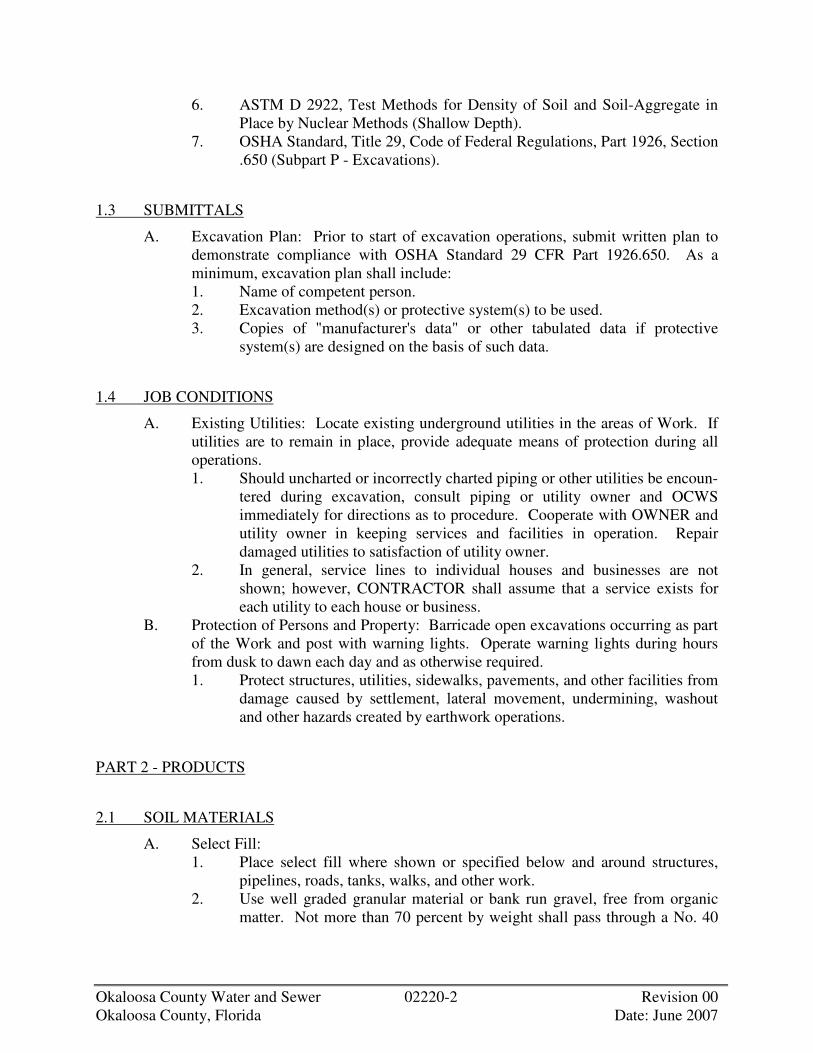
Okaloosa County Water and Sewer 02220-2 Revision 00 Okaloosa County, Florida Date: June 2007
6. ASTM D 2922, Test Methods for Density of Soil and Soil-Aggregate in Place by Nuclear Methods (Shallow Depth).
7. OSHA Standard, Title 29, Code of Federal Regulations, Part 1926, Section .650 (Subpart P - Excavations).
1.3 SUBMITTALS
A. Excavation Plan: Prior to start of excavation operations, submit written plan to demonstrate compliance with OSHA Standard 29 CFR Part 1926.650. As a minimum, excavation plan shall include: 1. Name of competent person. 2. Excavation method(s) or protective system(s) to be used. 3. Copies of "manufacturer's data" or other tabulated data if protective
system(s) are designed on the basis of such data.
1.4 JOB CONDITIONS
A. Existing Utilities: Locate existing underground utilities in the areas of Work. If utilities are to remain in place, provide adequate means of protection during all operations. 1. Should uncharted or incorrectly charted piping or other utilities be encoun-
tered during excavation, consult piping or utility owner and OCWS immediately for directions as to procedure. Cooperate with OWNER and utility owner in keeping services and facilities in operation. Repair damaged utilities to satisfaction of utility owner.
2. In general, service lines to individual houses and businesses are not shown; however, CONTRACTOR shall assume that a service exists for each utility to each house or business.
B. Protection of Persons and Property: Barricade open excavations occurring as part of the Work and post with warning lights. Operate warning lights during hours from dusk to dawn each day and as otherwise required. 1. Protect structures, utilities, sidewalks, pavements, and other facilities from
damage caused by settlement, lateral movement, undermining, washout and other hazards created by earthwork operations.
PART 2 - PRODUCTS
2.1 SOIL MATERIALS
A. Select Fill: 1. Place select fill where shown or specified below and around structures,
pipelines, roads, tanks, walks, and other work. 2. Use well graded granular material or bank run gravel, free from organic
matter. Not more than 70 percent by weight shall pass through a No. 40

Okaloosa County Water and Sewer 02220-3 Revision 00 Okaloosa County, Florida Date: June 2007
sieve; not more than 10 percent by weight shall pass through a No. 200 sieve; and 100 percent shall pass a 6-inch square sieve.
3. Advise OCWS in writing of source and, if required, submit a sample of the material for approval.
B. Subbase Material: Naturally or artificially graded mixture of natural or crushed gravel, crushed stone, crushed slag, or natural or crushed sand, approved by OCWS.
C. Drainage Fill: Washed, uniformly graded mixture of crushed stone, or crushed or uncrushed gravel, with 100 percent passing a 1-1/2 inch sieve and not more than 5 percent passing a No. 4 sieve.
D. General Backfill and Fill Materials: Provide approved soil materials for backfill and fill, free of clay, rock or gravel larger than 6 inches in any dimension, debris, waste, vegetable and other organic matter and other deleterious materials. Previously excavated materials meeting these requirements may be used for backfill.
PART 3 -EXECUTION
3.1 INSPECTION
A. Provide OCWS with sufficient notice and with means to examine the areas and conditions under which excavating, filling, and grading are to be performed. OCWS will notify CONTRACTOR if conditions are found that may be detrimental to the proper and timely completion of the Work. Do not proceed with the Work until unsatisfactory conditions have been corrected in an acceptable manner.
3.2 EXCAVATION
A. Perform all excavation required to complete the Work as shown, specified and required. Excavations shall include earth, sand, clay, gravel, hardpan, decomposed rock, pavements, rubbish and all other materials within the excavation limits.
B. Excavations for structures and pipelines shall be open excavations. Provide excavation protection system(s) required by ordinances, codes, law and regulations to prevent injury to workmen and to prevent damage to new and existing structures or pipelines. Unless shown or specified otherwise, protection system(s) shall be utilized under the following conditions. 1. Excavation Less Than 5 Feet Deep: Excavations in stable rock or in soil
conditions where there is no potential for a cave-in may be made with vertical sides. Under all other conditions, excavations shall be sloped and benched, shielded, or shored and braced.
2. Excavations More Than 5 Feet Deep: Excavations shall be sloped and benched, shielded or shored and braced.
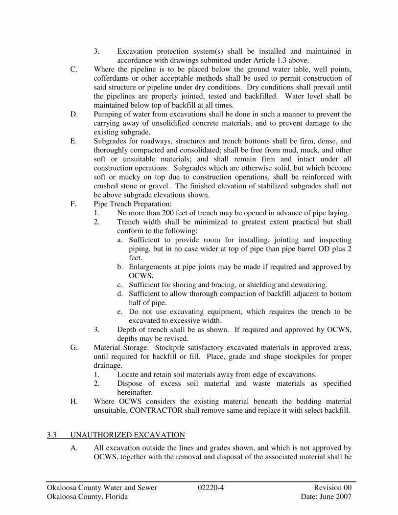
Okaloosa County Water and Sewer 02220-4 Revision 00 Okaloosa County, Florida Date: June 2007
3. Excavation protection system(s) shall be installed and maintained in accordance with drawings submitted under Article 1.3 above.
C. Where the pipeline is to be placed below the ground water table, well points, cofferdams or other acceptable methods shall be used to permit construction of said structure or pipeline under dry conditions. Dry conditions shall prevail until the pipelines are properly jointed, tested and backfilled. Water level shall be maintained below top of backfill at all times.
D. Pumping of water from excavations shall be done in such a manner to prevent the carrying away of unsolidified concrete materials, and to prevent damage to the existing subgrade.
E. Subgrades for roadways, structures and trench bottoms shall be firm, dense, and thoroughly compacted and consolidated; shall be free from mud, muck, and other soft or unsuitable materials; and shall remain firm and intact under all construction operations. Subgrades which are otherwise solid, but which become soft or mucky on top due to construction operations, shall be reinforced with crushed stone or gravel. The finished elevation of stabilized subgrades shall not be above subgrade elevations shown.
F. Pipe Trench Preparation: 1. No more than 200 feet of trench may be opened in advance of pipe laying. 2. Trench width shall be minimized to greatest extent practical but shall
conform to the following: a. Sufficient to provide room for installing, jointing and inspecting
piping, but in no case wider at top of pipe than pipe barrel OD plus 2 feet.
b. Enlargements at pipe joints may be made if required and approved by OCWS.
c. Sufficient for shoring and bracing, or shielding and dewatering. d. Sufficient to allow thorough compaction of backfill adjacent to bottom
half of pipe. e. Do not use excavating equipment, which requires the trench to be
excavated to excessive width. 3. Depth of trench shall be as shown. If required and approved by OCWS,
depths may be revised. G. Material Storage: Stockpile satisfactory excavated materials in approved areas,
until required for backfill or fill. Place, grade and shape stockpiles for proper drainage. 1. Locate and retain soil materials away from edge of excavations. 2. Dispose of excess soil material and waste materials as specified
hereinafter. H. Where OCWS considers the existing material beneath the bedding material
unsuitable, CONTRACTOR shall remove same and replace it with select backfill.
3.3 UNAUTHORIZED EXCAVATION
A. All excavation outside the lines and grades shown, and which is not approved by OCWS, together with the removal and disposal of the associated material shall be

Okaloosa County Water and Sewer 02220-5 Revision 00 Okaloosa County, Florida Date: June 2007
at CONTRACTOR'S expense. Unauthorized excavations shall be filled and compacted with select backfill by CONTRACTOR at his expense.
3.4 DRAINAGE AND DEWATERING
A. General: 1. Prevent surface and subsurface water from flowing into excavations and
from flooding adjacent areas. 2. Remove water from excavation as fast as it collects. 3. Maintain the ground water level below the bottom of the excavation to
provide a stable surface for construction operations, a stable subgrade for the permanent work, and to prevent damage to the Work during all stages of construction.
4. Provide and maintain pumps, sumps, suction and discharge lines and other dewatering system components necessary to convey water away from excavations.
5. Obtain OCWS' approval before shutting down dewatering system for any reason.
B. Standby Requirements for Dewatering: Provide standby equipment to insure continuity of dewatering operations.
C. Disposal of Water Removed by Dewatering System: 1. Dispose of all water removed from the excavation in such a manner as not
to endanger public health, property, or any portion of the Work under construction or completed.
2. Dispose of water in such a manner as to cause no inconvenience to OWNER, OCWS, or others involved in work about the site.
3. Convey water from the construction site in a closed conduit. Do not use trench excavations as temporary drainage ditches.
3.5 SHEETING, SHORING AND BRACING
A. General: 1. Used material shall be in good condition, not damaged or excessively
pitted. All steel or wood sheeting designated to remain in place shall be new. New or used sheeting may be used for temporary work.
2. All timber used for breast boards (lagging) shall be new or used, meeting the requirements for Douglas Fir Dense Construction grade with a bending strength not less than 1500 psi or Southern Pine No. 2 Dense.
3. All steel work for sheeting, shoring, bracing, cofferdams etc., shall be designed in accordance with the provisions of the "Specifications for the Design, Fabrication and Erection of Structural Steel for Buildings", of the AISC except that field welding will be permitted.
4. Steel sheet piling shall be manufactured from steel conforming to ASTM A 328. Steel for soldier piles, wales and braces shall be new or used and shall conform to ASTM A 36.

Okaloosa County Water and Sewer 02220-6 Revision 00 Okaloosa County, Florida Date: June 2007
5. Maintain shoring and bracing in excavations regardless of time period excavations will be open. Carry down shoring and bracing as excavation progresses.
6. Unless otherwise shown, specified, or ordered, all materials used for temporary construction shall be removed when work is completed. Such removal shall be made in a manner not injurious to the structure or its appearance or to adjacent Work.
7. Safe and satisfactory sheeting, shoring and bracing shall be the entire responsibility of CONTRACTOR.
B. Removal of Sheeting and Bracing: 1. Remove sheeting and bracing from excavations unless otherwise ordered
in writing by OCWS. Removal shall be done so as to not cause injury to the Work. Removal shall be equal on both sides of excavation to ensure no unequal loads on pipe or structure.
2. Defer removal of sheeting and bracing, where removal may cause soil to come into contact with concrete, until the following conditions are satisfied: a. Concrete has cured a minimum of 7 days. b. Wall and floor framing up to and including grade level floors are in
place.
3.6 TRENCH SHIELDS
A. Excavation of earth material below the bottom of a shield shall not exceed the limits established by ordinances, codes, laws and regulations.
B. When using a shield for pipe installation: 1. Any portion of the shield that extends below the mid-diameter of an
installed rigid pipe (i.e. RCCP) shall be raised above this point prior to moving the shield ahead for the installation of the next length of pipe.
2. The bottom of the shield shall not extend below the mid-diameter of installed flexible pipe (i.e. Steel, DI, PVC, etc.) at any time.
C. When using a shield for the installation of structures, the bottom of the shield shall not extend below the top of the bedding for the structures.
D. When a shield is removed or moved ahead, extreme care shall be taken to prevent the movement of pipe or structures or the disturbance of the bedding for pipe or structures. Pipe or structures that are disturbed shall be removed and reinstalled as specified.
3.7 GENERAL REQUIREMENTS FOR BACKFILL, FILL, AND COMPACTION
A. Furnish, place and compact all backfill required for structures, trenches and to provide the finished grades shown and specified. Unless otherwise specified fill may be obtained from on-site sources.
B. Backfill excavations as promptly as Work permits, but not until completion of the following:

Okaloosa County Water and Sewer 02220-7 Revision 00 Okaloosa County, Florida Date: June 2007
1. Acceptance by OCWS of construction below finish grade including dampproofing, waterproofing, and perimeter insulation.
2. Inspection, testing, approval, and recording of locations of underground utilities.
3. Removal of concrete formwork. 4. Removal of shoring and bracing. 5. Removal of trash and debris. 6. Permanent or temporary horizontal bracing is in place on horizontally
supported walls. C. Keep excavations dry during backfilling operations. Bring backfill around piping
up evenly on all sides. D. Place all backfilling in pipe trenches, which are below structures, other pipes, or
paved areas, in horizontal layers not exceeding 6 inches in depth and thoroughly compact each before the next layer is placed. In other pipe trenches, compacted layers shall be 6 inches up to the pipe centerline and 12 inches thereafter.
E. Prior to the installation of pipes which are to be installed in fill sections, place the fill as described herein, until a minimum height of 2 feet above the pipe is reached, unless otherwise required in other Sections. The fill for the trench width shall then be excavated and the pipe installed and backfilled. The remainder of the fill shall then be placed.
F. Unless otherwise specified or directed by OCWS fill shall be placed in horizontal loose lifts not exceeding 8 inches in thickness and shall be mixed and spread in a manner assuring uniform lift thickness after placing.
G. Control the water content of fill material during placement within the range necessary to obtain the compaction specified. In general, the moisture content of the fill shall be within 3 percent of the optimum moisture content for compaction as determined by laboratory tests. Perform all necessary work to adjust the water content of the material to within the range necessary to permit the compaction specified. Do not place fill material when free water is standing on the surface of the area where the fill is to be placed. No compaction of fill will be permitted with free water on any portion of the fill to be compacted.
H. Perform Compaction of fill with equipment suitable for the type of material placed and which is capable of providing the densities required. CONTRACTOR shall select compaction equipment and submit it and his proposed procedure to OCWS for approval.
I. Compact fill shall be compacted by at least two coverages of all portions of the surface of each lift by compaction equipment. One coverage is defined as the condition obtained when all portions of the surface of the fill material have been subjected to the direct contact of the compactor.
J. Test the effectiveness of the equipment selected by CONTRACTOR at the commencement of compaction by construction of a small section of fill within the area where fill is to be placed. If tests on this section of fill show that the specified compaction is not obtained, CONTRACTOR shall increase the number of coverages, decrease the lift thicknesses or obtain a different type of compactor.
K. If the specified densities are not obtained because of improper control of placement or compaction procedures, or because of inadequate or improperly

Okaloosa County Water and Sewer 02220-8 Revision 00 Okaloosa County, Florida Date: June 2007
functioning compaction equipment, the CONTRACTOR shall perform whatever work is required to provide the required densities. This work shall include complete removal of unacceptable fill areas, and replacement and recompaction until acceptable fill is provided.
L. CONTRACTOR shall repair, at his own expense, any after settlement that occurs. He shall make all repairs and replacements necessary within 30 days after notice from OCWS or OWNER.
3.8 SELECT FILL
A. Provide select fill in the following locations: 1. Support below and around piping and foundations. 2. Subgrade for roads and pavements. 3. Where shown or directed by OCWS.
B. Subgrade surface shall be level, dry, firm and subject to OCWS' approval. Do not place fill if any water is on the surface of area to receive fill.
C. Place fill in horizontal loose lifts of 8 inches maximum thickness. It shall be mixed and spread in a manner to assure uniform lift thickness after placing.
D. Compact each layer of fill before placement of the next lift. E. Do not use fill containing lumps, pockets or concentrations of silt or clay, rubble,
debris, wood or other organic matter. Fill containing unacceptable material shall be removed and disposed of.
F. The water content of the fill being compacted shall be above the bulking water content for the material. CONTRACTOR shall wet the fill materials during placement to achieve water contents needed for effective compaction.
G. Perform compaction of fill with equipment suitable for the type of fill material being placed. Select equipment, which is capable of providing the densities required, and submit selection of the equipment to OCWS for approval.
H. Compact each layer of fill material by at least two complete coverages of all portions of the surface of each lift using approved compaction equipment. One coverage is defined as the condition reached when all portions of the fill lift have been subjected to the direct contact of the compacting surface of the compactor.
I. The minimum density to be obtained in compacting the select fill shall be 95 percent of maximum density obtained in the laboratory in accordance with ASTM D 1557 Method C including Note 2. This percentage is of Modified Proctor density. If the field and laboratory tests indicate unsatisfactory compaction, CONTRACTOR shall provide the additional compaction necessary to obtain the specified degree of compaction. All additional compaction work shall be performed by CONTRACTOR at no additional cost to OWNER until the specified compaction is obtained.
J. Select fill necessary to replace subgrade materials disturbed and softened as a result of CONTRACTOR'S operations or to backfill unauthorized excavation shall be provided, placed and compacted at CONTRACTOR'S expense.

Okaloosa County Water and Sewer 02220-9 Revision 00 Okaloosa County, Florida Date: June 2007
3.9 UNCOMPACTED BACKFILL
A. Compaction of trench backfill above top of pipe in locations other than those specified will not be required except to the extent necessary to prevent future settlement.
B. Place material above embedments so that no excessive or unbalanced load, shock or impact occurs on the pipe or results in displacement of the pipe.
3.10 GRADING
A. General: Uniformly grade areas within limits of grading under this Section, including adjacent transition areas. Smooth subgrade surfaces within specified tolerances, compact with uniform levels or slopes between points where elevations are shown, or between such points and existing grades.
3.11 DISPOSAL OF EXCAVATED MATERIALS
A. Material removed from the excavations which does not conform to the requirements for fill or is in excess of that required for backfill shall be hauled away from the project site by the CONTRACTOR and disposed of in compliance with ordinances, codes, laws and regulations at no additional cost to the OWNER.
3.12 RESTORING AND RESURFACING EXISTING ROADWAYS AND FACILITIES
A. Place 1-1/2 inches of temporary bituminous pavement immediately after backfilling trenches in paved roadways, which are to be retained for permanent use. Maintain the surface of the paved area over the trench in good and safe condition during progress of the entire Work, and promptly fill all depressions over and adjacent to the trench caused by settlement of backfilling. The permanent replacement pavement shall be equal to that of the existing roadways unless otherwise specified.
B. Pavement, gutters, curbs, sidewalks or roadways disturbed or damaged by the CONTRACTOR'S operations, except areas designated "New Pavement" or "Proposed Pavement", shall be restored by him at his own expense to as good condition as they were previous to the commencement of the Work and in accordance with applicable local and state highway specifications.


Okaloosa County Water and Sewer 02512-1 Revision 00 Okaloosa County, Florida Date: June 2007
SECTION 02512
BITUMINOUS PAVING
PART 1 - GENERAL
1.1 DESCRIPTION
A. Scope: 1. CONTRACTOR shall provide all labor, materials, equipment and
incidentals as shown, specified or required to furnish and install hot mix-hot laid bituminous paving.
2. The Work includes the following: a. Coarse graded base course. b. Fine graded surface course. c. Pavement marking. d. Testing as specified.
B. Related Sections: 1. Section 02220, Excavation and Backfill.
1.2 QUALITY ASSURANCE
A. Tests: 1. The services of a qualified testing laboratory shall be engaged by
CONTRACTOR to make tests and determine acceptability of the pavement materials. The laboratory shall be acceptable to OCWS.
2. Required Tests: a. Refer to State Highway Department requirements.
B. Reference Standards: Comply with the applicable provisions and recommendations of the following, unless otherwise shown or specified. 1. Standard Specifications for Road Work of the State of Florida. 2. Federal Specification (FS) TT-P-115, Paint, Traffic, Highway, White and
Yellow.
1.3 SUBMITTALS
A. Shop Drawings: Submit for approval the following: 1. Job mix formula proposed, giving complete data on materials, including
source, location, percentages, temperatures, and all other pertinent data. B. Material Certificates:
1. In lieu of laboratory reports required in the State Standards, CONTRACTOR may submit certificates of compliance for the following: a. Coarse and fine aggregates from each material source and each
required grading. b. Asphalt or tar cement for each penetration grade.
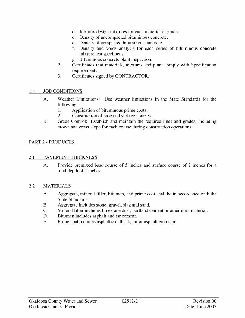
Okaloosa County Water and Sewer 02512-2 Revision 00 Okaloosa County, Florida Date: June 2007
c. Job-mix design mixtures for each material or grade. d. Density of uncompacted bituminous concrete. e. Density of compacted bituminous concrete. f. Density and voids analysis for each series of bituminous concrete
mixture test specimens. g. Bituminous concrete plant inspection.
2. Certificates that materials, mixtures and plant comply with Specification requirements.
3. Certificates signed by CONTRACTOR.
1.4 JOB CONDITIONS
A. Weather Limitations: Use weather limitations in the State Standards for the following: 1. Application of bituminous prime coats. 2. Construction of base and surface courses.
B. Grade Control: Establish and maintain the required lines and grades, including crown and cross-slope for each course during construction operations.
PART 2 - PRODUCTS
2.1 PAVEMENT THICKNESS
A. Provide premixed base course of 5 inches and surface course of 2 inches for a total depth of 7 inches.
2.2 MATERIALS
A. Aggregate, mineral filler, bitumen, and prime coat shall be in accordance with the State Standards.
B. Aggregate includes stone, gravel, slag and sand. C. Mineral filler includes limestone dust, portland cement or other inert material. D. Bitumen includes asphalt and tar cement. E. Prime coat includes asphaltic cutback, tar or asphalt emulsion.

Okaloosa County Water and Sewer 02512-3 Revision 00 Okaloosa County, Florida Date: June 2007
2.3 BITUMINOUS-AGGREGATE MIXTURES
A. Job-Mix Criteria: 1. Provide job mix formulas as follows:
a. Base Course:
Sieve Designation Percent (Square Opening) Passing
2-1/4 inches 100 1-1/2 inches 80-100
3/4 inch 55-80 3/8 inch 35-60 No. 10 15-35 No. 40 5-20
No. 200 2-10 Bitumen (percent) 3.5 - 6.0
b. Surface Course:
Sieve Designation Percent (Square Opening) Passing
3/4 inch 100 1/2 inch 80-100 3/8 inch 70-100
No. 4 50-79 No. 10 33-60 No. 40 16-37 No. 80 9-23
No. 200 2-8 Bitumen (percent) 4.0 - 8.0
2.4 TRAFFIC AND PARKING MARKING MATERIALS
A. Traffic lane marking paint with chlorinated rubber base. B. Factory mixed, quick drying and non bleeding, FS TT-P-115, Type III.
PART 3 - EXECUTION
3.1 INSPECTION
A. Examine the subgrade on which bituminous concrete will be installed. Notify OCWS in writing of conditions detrimental to the proper and timely completion

Okaloosa County Water and Sewer 02512-4 Revision 00 Okaloosa County, Florida Date: June 2007
of the Work. Do not proceed with the Work until unsatisfactory conditions have been corrected in a manner acceptable to OCWS.
3.2 PRIME COAT
A. Apply prime coat to subgrade in accordance with the requirements of the State Standards.
3.3 FRAME ADJUSTMENT
A. Set frames of drainage structures to final grade in an approved manner. Include existing frames and frames furnished under other Sections of these Specifications.
3.4 PAVEMENT INSTALLATION
A. Preparing the mixtures, paving equipment, placing the mixes, and compacting the mixes shall be in accordance with the State Standards.
B. Preparing the mixtures includes the plant equipment, stockpiling, heating, aggregate processing, mixing of aggregate and bituminous material, and transporting to job site.
C. Paving equipment includes bituminous pavers, rolling equipment and hand tools. D. Placing the mixes includes paver placing, hand placing, spreading, tamping and
jointing. E. Compacting the mixes includes breakdown rolling, second rolling and finish
rolling.
3.5 PAVEMENT QUALITY REQUIREMENTS
A. General: In addition to other specified conditions, comply with the following minimum requirements: 1. Provide final surfaces of uniform texture, conforming to required grades
and cross sections. 2. Take not less than one 4-inch diameter pavement specimen for each
complete course for each 10,000 square feet of pavement, if directed by OCWS.
3. Repair holes from test specimens as specified for patching defective work. B. Density:
1. If directed by OCWS, compare density of in-place material against laboratory specimen or certificates on same bituminous concrete mixture. Use nuclear devices.
2. Minimum acceptable density of in-place course material will be 90 percent of the recorded laboratory specimen or certificate density. Maximum acceptable density will be 98 percent.
C. Thickness: In-place compacted thickness shall average not less than the thickness specified.
D. Surface Smoothness:

Okaloosa County Water and Sewer 02512-5 Revision 00 Okaloosa County, Florida Date: June 2007
1. Test finished surface of each bituminous concrete course for smoothness, using a 10-foot straightedge applied parallel to and at right angles to centerline of paved areas.
2. Check surfaced areas at intervals directed by OCWS. 3. Surfaces will not be acceptable if exceeding the following:
a. Base Course: 3/8 inch in 10 feet. b. Surface Course: 1/4 inch in 10 feet. c. Crowned Surfaces:
1) Test crowned surfaces with a crown template, centered and at right angles to the crown.
2) Surfaces will not be acceptable if varying more than 1/4 inch from the template.
3.6 PATCHING
A. As directed by OCWS, remove and replace all defective areas. Cut out such areas and fill with fresh bituminous concrete. Compact to the required density.
3.7 CLEANING AND PROTECTION
A. Cleaning: After completion of paving operations, clean surfaces of excess or spilled bituminous materials and all foreign matter.
B. Protect newly finished pavement until it has become properly hardened by cooling.
C. Cover openings of drainage structures in the area of paving until permanent coverings are placed.
3.8 MARKING PAVEMENT
A. Cleaning: 1. Sweep surface with power broom supplemented by hand brooms to
remove loose material and dirt. 2. Do not begin marking bituminous concrete pavement until approved by
OCWS. B. Application:
1. Using mechanical equipment, provide uniform straight edges in two separate coats. Apply in accordance with paint manufacturer's recommended rates.


Okaloosa County Water and Sewer 02606-1 Revision 00 Okaloosa County, Florida Date: June 2007
SECTION 02606
MANHOLES
PART 1 - GENERAL
1.1 DESCRIPTION
A. Scope: CONTRACTOR shall provide all labor, materials, equipment and incidentals as shown, specified and required to furnish and install all precast, cast-in-place and masonry manholes.
B. General: 1. Manholes shall conform in shape, size, dimensions, material, and other
respects to the details shown or as ordered by OCWS. 2. Cast-iron frames, grates and covers shall be the standard frame and grate
or cover unless otherwise shown. 3. Concrete for cast-in-place manholes and for inverts in precast and
masonry manholes shall be Class A and shall conform to the requirements specified under Section 03300.
C. Related Sections: 1. Division 2 Sections on Earthwork. 2. Section 03300, Cast-In-Place Concrete. 3. Division 15 Sections on Piping.
1.2 QUALITY ASSURANCE
A. Reference Standards: 1. ASTM C 32, Specification for Sewer and Manhole Brick (made from Clay
or Shale). 2. ASTM C 139, Specification for Concrete Masonry Units for Construction
of Catch Basins and Manholes. 3. ASTM C 140, Method of Sampling and Testing Concrete Masonry Units. 4. ASTM C 207, Specification for Hydrated Lime for Masonry Purposes. 5. ASTM C 478, Specification for Precast Reinforced Concrete Manhole
Sections. 6. AWWA C302, Reinforced Concrete Pressure Pipe, Noncylinder Type, for
Water and Other Liquids.
1.3 SUBMITTALS
A. Shop Drawings: Submit for approval the following: 1. Drawings showing design and construction details of all precast concrete
and cast-in-place manholes including details of joints between the manhole bases and riser sections and stubs or openings for the connection of sewers.
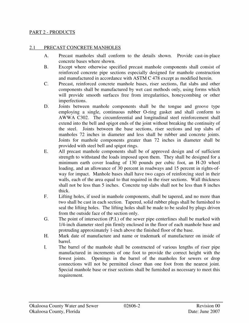
Okaloosa County Water and Sewer 02606-2 Revision 00 Okaloosa County, Florida Date: June 2007
PART 2 - PRODUCTS
2.1 PRECAST CONCRETE MANHOLES
A. Precast manholes shall conform to the details shown. Provide cast-in-place concrete bases where shown.
B. Except where otherwise specified precast manhole components shall consist of reinforced concrete pipe sections especially designed for manhole construction and manufactured in accordance with ASTM C 478 except as modified herein.
C. Precast, reinforced concrete manhole bases, riser sections, flat slabs and other components shall be manufactured by wet cast methods only, using forms which will provide smooth surfaces free from irregularities, honeycombing or other imperfections.
D. Joints between manhole components shall be the tongue and groove type employing a single, continuous rubber O-ring gasket and shall conform to AWWA C302. The circumferential and longitudinal steel reinforcement shall extend into the bell and spigot ends of the joint without breaking the continuity of the steel. Joints between the base sections, riser sections and top slabs of manholes 72 inches in diameter and less shall be rubber and concrete joints. Joints for manhole components greater than 72 inches in diameter shall be provided with steel bell and spigot rings.
E. All precast manhole components shall be of approved design and of sufficient strength to withstand the loads imposed upon them. They shall be designed for a minimum earth cover loading of 130 pounds per cubic foot, an H-20 wheel loading, and an allowance of 30 percent in roadways and 15 percent in rights-of-way for impact. Manhole bases shall have two cages of reinforcing steel in their walls, each of the area equal to that required in the riser sections. Wall thickness shall not be less than 5 inches. Concrete top slabs shall not be less than 8 inches thick.
F. Lifting holes, if used in manhole components, shall be tapered, and no more than two shall be cast in each section. Tapered, solid rubber plugs shall be furnished to seal the lifting holes. The lifting holes shall be made to be sealed by plugs driven from the outside face of the section only.
G. The point of intersection (P.I.) of the sewer pipe centerlines shall be marked with 1/4-inch diameter steel pin firmly enclosed in the floor of each manhole base and protruding approximately 1-inch above the finished floor of the base.
H. Mark date of manufacture and name or trademark of manufacturer on inside of barrel.
I. The barrel of the manhole shall be constructed of various lengths of riser pipe manufactured in increments of one foot to provide the correct height with the fewest joints. Openings in the barrel of the manholes for sewers or drop connections will not be permitted closer than one foot from the nearest joint. Special manhole base or riser sections shall be furnished as necessary to meet this requirement.

Okaloosa County Water and Sewer 02606-3 Revision 00 Okaloosa County, Florida Date: June 2007
J. A precast or cast-in-place slab or precast eccentric cone, as shown or approved, shall be provided at the top of the manhole barrel to receive the cast iron frame and cover.
K. Manhole sections shall contain manhole steps, 12 inches on centers, accurately positioned and embedded in the concrete. Steps are specified under Section 05501.
2.2 MASONRY MANHOLES
A. Masonry manholes, where shown or otherwise approved by OCWS, shall conform to the following: 1. Brick: Brick shall conform to the requirements of ASTM C 32, Grade SS
for sewer brick and Grade MS for manhole brick. 2. Concrete Blocks: Concrete blocks shall be machine-made, solid
segmental blocks not less than 8 inches wide and shaped so that the completed structure in which they are used will conform to the details shown or otherwise approved. Blocks shall be of compact texture and like blocks shall be uniform in shape and size.
3. Concrete blocks shall conform to ASTM C 139. Testing of blocks shall be done in accordance with ASTM C 140.
4. Mortar: The mortar shall be composed of portland cement, hydrated lime, and sand, in which the volume of sand shall not exceed three times the sum of the volumes of cement and lime.
5. Cement shall be Type II portland cement as specified for concrete masonry.
6. Hydrated lime shall be Type S conforming to ASTM C 207. 7. The sand shall comply with the Specifications for "Fine Aggregate" for
concrete except that all of the sand shall pass a No. 8 sieve. 2.3 MISCELLANEOUS METALS
A. Metal frames, covers, steps, toe pockets and similar required items shall be provided as shown and in accordance with Division 5 Sections on Metal Fabrications.
2.4 DROP CONNECTIONS
A. Drop connections for manholes shall be constructed where shown or ordered and shall conform to the design and details shown. Pipe and fittings shall be ductile iron, reinforced concrete, or vitrified clay as shown or otherwise approved. Concrete for pipe encasement shall be Class B as specified under Section 03300. Concrete shall be bonded to manhole in the manner shown or otherwise approved by OCWS.

Okaloosa County Water and Sewer 02606-4 Revision 00 Okaloosa County, Florida Date: June 2007
PART 3 - EXECUTION
3.1 LAYING MASONRY
A. Brick shall be satisfactorily wet when being laid and each brick shall be laid in mortar so as to form full bed, end and side joints in one operation. The joints shall not be wider than 3/8-inch, except when the bricks are laid radially, in which case the narrowest part of the joint shall not exceed 1/4-inch. Masonry work shall be kept moist for a period of three days after completion, and precautions shall be taken to prevent freezing during cold weather.
B. For concrete block, the vertical keyways shall be completely filled with mortar. C. Each grading ring shall be laid in a full bed of mortar and shall be thoroughly
bonded.
3.2 PLASTERING
A. The outside of brick manholes, brick stacks and grading rings shall be neatly plastered with 1/2 inch of cement mortar as the Work progresses.
3.3 MANHOLE BASES
A. Cast-in-place bases shall be placed on suitable foundations after the pipes are laid. They shall be cast monolithically to an elevation at least 12 inches above the top of the highest pipe entering the manhole, except where a drop connection is to be installed. Base, walls and bottom shall be at least of the thickness shown and reinforced to withstand the loads to be expected. Connections for sewer pipes shall conform to the details shown.
B. Precast bases shall be set on a crushed stone or crushed gravel foundation as shown. Precast bases shall be set at the proper grade and carefully leveled and aligned.
3.4 PRECAST MANHOLE SECTIONS
A. Set sections vertical with steps and sections in true alignment. The base of the bell or groove end at joints between components shall be buttered with 1:2 cement-sand mortar to provide a uniform bearing between components. All joints shall be sealed with cement mortar inside and out and troweled smooth to the contour of the wall surface. Raised or rough joint finishes will not be accepted.
B. Install sections, joints and gaskets in accordance with manufacturers recommendations.
C. Lifting holes shall be sealed tight with a solid rubber plug driven into the hole from the outside of the barrel and the remaining void filled with 1 to 2 cement-sand mortar.

Okaloosa County Water and Sewer 02606-5 Revision 00 Okaloosa County, Florida Date: June 2007
3.5 MANHOLE CHANNELS
A. All invert channels through manholes shall be constructed of Class A concrete. Channels shall be properly formed to the sizes, cross sections, grades and shapes shown or as ordered. Benches shall be built up to the heights shown or as ordered and given a uniform wood float finish. Care shall be taken to slope all benches for proper drainage to the invert channel.
3.6 GRADING RINGS
A. Grading rings or brick stacks shall be used for all precast and masonry manholes where required. Stacks or grade rings shall be a maximum of 12 inches in height, constructed on the roof slab or cone section on which the manhole frame and cover shall be placed. The height of the stack or grade rings shall be such as is necessary to bring the manhole frame to the proper grade.
B. Brick work shall be as specified in Articles 2.2 and 3.1 above.
3.7 STUBS FOR FUTURE CONNECTIONS
A. As shown or required for connections, cast iron sleeves, asbestos-cement couplings, bell end tile, ductile iron or reinforced concrete pipe stubs with approved watertight plugs shall be installed in manholes. Where pipe stubs, sleeves or couplings for future connections are shown or ordered, CONTRACTOR shall provide all materials and work for their construction.
3.8 GRADING AT MANHOLES
A. All manholes in unpaved areas shall be built as shown or directed to an elevation higher than the original ground. The ground surface shall be graded to drain away from the manhole. Fill shall be placed around manholes to the level of the upper rim of the manhole frame, and the surface evenly graded on a 1 to 5 slope to the existing surrounding ground unless otherwise shown. The slop shall be covered with 4 inches of top soil, seeded and maintained until a satisfactory growth of grass is obtained.
B. Manholes in paved areas shall be constructed to meet the final surface grade. In paved areas on State Highways, all manholes shall be 1/2 inch below final wearing surfaces. Manholes shall not project above finished roadway pavements to prevent damage from snowplows.
C. CONTRACTOR shall be solely responsible for the proper height of all manholes necessary to reach the final grade at all locations. CONTRACTOR is cautioned that OCWS'S review of Shop drawings for manhole components will be general in nature and CONTRACTOR shall provide an adequate supply of random length precast manhole riser sections to adjust any manhole to meet field conditions for final grading.
Okaloosa County Water and Sewer 02606-6 Revision 00 Okaloosa County, Florida Date: June 2007
3.9 MANHOLE WATERTIGHTNESS
A. All manholes shall be free of visible leakage. Each manhole shall be tested for leaks and inspected, and all leaks shall be repaired in a manner subject to OCWS' approval.
3.10 FLEXIBLE PIPE JOINT AT MANHOLE BASE
A. An approved flexible joint shall be provided between each pipe entering and exiting the manhole. This may be accomplished by the installation in the manhole base of the bell end of a pipe or by other means subject to approval of OCWS. Joints shall be similar to the approved pipe joints. The joint into the manhole base shall be completely watertight.

OKALOOSA COUNTY WATER AND SEWER
DIVISION 3
Okaloosa County Water and Sewer Revision 00 Okaloosa County, Florida Date: June 2007
DIVISION 3 CONCRETE
SECTION 03300 CONCRETE


Okaloosa County Water and Sewer 03300-1 Revision 00 Okaloosa County, Florida Date: June 2007
SECTION 03300
CONCRETE
PART 1 - GENERAL
1.1 DESCRIPTION
A. Scope: 1. CONTRACTOR shall provide all labor, materials, equipment and
incidentals as shown, specified and required to furnish and install cast-in-place concrete, reinforcement and related materials.
B. Coordination: 1. Review installation procedures under other Sections and coordinate the
installation of items that must be installed in the concrete. 2. Notify other contractors in advance of the placing of concrete to provide
the other contractors with sufficient time for furnishing of items included in their contracts that must be installed in the concrete.
C. General: 1. Class "A" concrete shall be steel reinforced and includes the following:
a. Cast-in-place manholes. b. Precast manholes. c. Other reinforced concrete structures.
2. Class "B" concrete shall be placed without forms or with simple forms, with little or no reinforcing, and includes the following: a. Concrete fill. b. Curbs and gutters. c. Sidewalks. d. Encasements, etc.
3. Steel Reinforcement: Includes bars, ties, supports and welded wire fabric.
1.2 QUALITY ASSURANCE
A. Source Quality Control: 1. Concrete Testing Service:
a. CONTRACTOR shall employ acceptable testing laboratory to perform materials evaluation, testing and design of concrete mixes.
b. OWNER will employ a separate testing laboratory to evaluate concrete delivered to and placed at the site.
c. CONTRACTOR'S laboratory shall also evaluate concrete delivered to and placed at the site.
2. Certificates, signed by concrete producer and CONTRACTOR, may be submitted in lieu of material testing when acceptable to OCWS.
3. Quality Control: Perform sampling and testing during concrete placement, as follows:

Okaloosa County Water and Sewer 03300-2 Revision 00 Okaloosa County, Florida Date: June 2007
4. Quality Control: OWNER'S testing laboratory will perform sampling and testing during concrete placement, as follows: a. Sampling: ASTM C 172. b. Slump: ASTM C 143, one test for each load at point of discharge. c. Air Content: ASTM C 31, one for each set of compressive strength
specimens. d. Compressive Strength: ASTM C 39, one set for each 50 cubic yards
or fraction thereof of each class of concrete; 1 specimen tested at 7 days, 2 specimens tested at 28 days. 1) When the total quantity of concrete is less than 50 cubic yards, the
strength tests may be waived by OCWS if field experience indicates evidence of satisfactory strength.
5. Report test results in writing to OCWS on same day tests are made. B. Reference Standards: Comply with the applicable provisions and
recommendations of the following, except as otherwise shown or specified. 1. ACI 301, Specifications for Structural Concrete for Buildings (includes
ASTM Standards referred to herein except ASTM A 36). 2. ACI 304, Guide for Measuring, Mixing, Transporting, and Placing
Concrete. 3. ACI 305, Hot Weather Concreting. 4. ACI 306, Cold Weather Concreting. 5. ACI 315, Manual of OCWSing and Placing Drawings for Reinforced
Concrete Structures. 6. ACI 318, Building Code Requirements for Reinforced Concrete. 7. ACI 347, Guide to Formwork for Concrete. 8. ACI 350, Environmental OCWSing Concrete Structures. 9. ASTM A 36, Specification for Structural Steel. 10. Concrete Reinforcing Steel Institute, Manual of Standard Practice,
includes ASTM Standards referred to herein.
1.3 SUBMITTALS
A. Samples: Submit samples of materials as specified and may be requested by OCWS, including names, sources and descriptions.
B. Shop Drawings: Submit for approval the following: 1. Copies of manufacturer's specifications with application and installation
instructions for proprietary materials and items, including admixtures and bonding agents.
2. Drawings for fabrication, bending, and placement of concrete reinforcement. Comply with ACI 315, Chapters 1 thru 7. For walls, show elevations to a minimum scale of 1/4-inch to 1 foot. Show bar schedules, stirrup spacing, diagrams of bent bars, arrangements and assemblies, as required for the fabrication and placement of concrete reinforcement.
3. List concrete materials and concrete mix designs proposed for use. Include the results of all tests performed to qualify the materials and to establish the mix designs in accordance with ACI 301, 3.9. Submit

Okaloosa County Water and Sewer 03300-3 Revision 00 Okaloosa County, Florida Date: June 2007
written report to OCWS for each proposed concrete mix at least 15 days prior to start of Work. Do not begin concrete production until mixes have been reviewed and are acceptable to OCWS. Mix designs may be adjusted when material characteristics, job conditions, weather, test results or other circumstances warrant. Do not use revised concrete mixes until submitted to and accepted by OCWS.
C. Laboratory Test Reports: Submit copies of laboratory test reports for concrete cylinders, materials and mix design tests. OCWS' review will be for general information only. Production of concrete to comply with specified requirements is the responsibility of CONTRACTOR.
1.4 PRODUCT DELIVERY, STORAGE, AND HANDLING
A. Deliver concrete reinforcement materials to the site bundled, tagged and marked. Use metal tags indicating bar size, lengths, and other information corresponding to markings shown on placement diagrams.
B. All materials used for concrete must be kept clean and free from all foreign matter during transportation and handling and kept separate until measured and placed in the mixer. Bins or platforms having hard clean surfaces shall be provided for storage. Suitable means shall be taken during hauling, piling and handling to insure that segregation of the coarse and fine aggregate particles does not occur and the grading is not affected.
PART 2 - PRODUCTS
2.1 CONCRETE MATERIALS
A. Portland Cement: ASTM C 150, Type II. B. Aggregates: ASTM C 33.
1. Fine Aggregate: Clean, sharp, natural sand free from loam, clay, lumps or other deleterious substances. Dune sand, bank run sand and manufactured sand are not acceptable.
2. Coarse Aggregate: Clean, uncoated, processed aggregate containing no clay, mud, loam, or foreign matter, as follows: a. Crushed stone, processed from natural rock or stone. b. Washed gravel, either natural or crushed. Use of slag and pit or bank
run gravel is not permitted. C. Coarse Aggregate Size: Size to be ASTM C 33, Nos. 57 or 67, unless permitted
otherwise by OCWS. D. Water: Clean, drinkable. E. Air-Entraining Admixture: ASTM C 260. F. Water-Reducing Admixture: ASTM C 494, Type A. Only use admixtures that
have been tested and accepted in mix designs. G. Water-Reducing High Range Admixture: ASTM C 494, Type F/G. Only use
admixtures that have been tested and accepted in mix designs.

Okaloosa County Water and Sewer 03300-4 Revision 00 Okaloosa County, Florida Date: June 2007
2.2 FORM MATERIALS
A. Provide form materials with sufficient stability to withstand pressure of placed concrete without bow or deflection.
B. Exposed Concrete Surfaces: Acceptable panel-type to provide continuous, straight, smooth, as-cast surfaces. Use largest practical sizes to minimize form joints.
C. Unexposed Concrete Surfaces: Suitable material to suit project conditions. D. Provide 3/4-inch chamfer at all exposed corners.
2.3 REINFORCING MATERIALS
A. Reinforcing Bars: ASTM A 615, Grade 60. B. Welded Wire Fabric: ASTM A 185. C. Steel Wire: ASTM A 82. D. Supports for Reinforcement: Bolsters, chairs, spacers and other devices for
spacing, supporting and fastening reinforcement in place. 1. Use wire bar type supports complying with CRSI recommendations,
except as specified below. Do not use wood, brick, or other unacceptable materials.
2. For slabs on grade, use supports with sand plates or horizontal runners where base materials will not support chair legs.
3. For all concrete surfaces, where legs of supports are in contact with forms, provide supports complying with CRSI, Manual of Standard Practice as follows: a. Either hot-dip galvanized, plastic protected or stainless steel legs.
4. Over waterproof membranes, use precast concrete chairs. E. Slump Limits:
1. Proportion and design mixes to result in concrete slump at the point of placement of not less than 1 inch and not more than 4 inches.
2. Class "A" and "B" Concrete: Proportion and design mixes to result in concrete slump at point of placement of not less than 1 inch and not more than 4 inches.
3. Class "C" Concrete: Proportion and design mixes to result in concrete slump: a. Not more than 4 inches prior to adding high range water-reducer. b. Not more than 8 inches at point of placement after adding high range
water-reducer.
2.4 RELATED MATERIALS
A. Waterstops: 1. Flat dumbbell or centerbulb type, size to suit joints, uniform minimum
thickness of 3/8-inch by 9-inches minimum width of Polyvinyl Chloride. a. Manufacturer: Provide waterstops of one of the following:
1) W.R. Meadows, Incorporated. 2) A.C. Horn, Incorporated.
Okaloosa County Water and Sewer 03300-5 Revision 00 Okaloosa County, Florida Date: June 2007
3) Or equal. B. Moisture Barrier: Clear 8 mils thick polyethylene; polyethylene-coated barrier
paper; 1/8-inch thick asphalt core membrane sheet. C. Joint Fillers:
1. Provide preformed expansion joint filler complying with ASTM D 1752, Type II Cork.
2.5 GROUT
A. Nonshrink, Nonmetallic Grout: 1. Prepackaged nonstaining cementitious grout requiring only the addition of
water at the job site. 2. Product and Manufacturer: Provide one of the following:
a. Euco N-S, as manufactured by the Euclid Chemical Company. b. Masterflo 713, as manufactured by Master Builders Company. c. Or equal.
B. Nonshrink, Nonmetalic 100% Solids, High Strength Epoxy Grout: 1. Use prepackaged solvent-free, moisture-insensitive, 3-component epoxy
grouting system. 2. Product and Manufacturer: Provide one of the following:
a. Euco High Strength Grout, as manufactured by the Euclid Chemical Company, Cleveland, OH.
b. Sikadur 42, Grout-Pak, as manufactured by the Sika Chemical Company, Lyndhurst, NJ.
c. Or equal. C. Ordinary Cement-Sand Grout:
1. Except where otherwise specified use 1 part cement to 3 parts sand complying with the following: a. Cement: ASTM C 150, Type II. b. Sand: ASTM C 33.
PART 3 - EXECUTION
3.1 INSPECTION
A. CONTRACTOR and his installer shall examine the substrate and the conditions under which Work is to be performed and notify OCWS in writing of unsatisfactory conditions. Do not proceed with the Work until unsatisfactory conditions have been corrected in a manner acceptable to OCWS.
3.2 FORMWORK
A. Formwork: Construction so that concrete members and structures are correct size, shape, alignment, elevation and position, complying with ACI 347.

Okaloosa County Water and Sewer 03300-6 Revision 00 Okaloosa County, Florida Date: June 2007
B. Provide openings in formwork to accommodate Work of other trades. Accurately place and securely support items built into forms.
C. Clean and adjust forms prior to concrete placement. Apply form release agents or wet forms, as required. Retighten forms during and after concrete placement if required to eliminate mortar leaks.
3.3 REINFORCEMENT, JOINTS, AND EMBEDDED ITEMS
A. Comply with the applicable recommendations of specified codes and standards, and CRSI, Manual of OCWSing and Placing Drawings, for details and methods of reinforcement placement and supports.
B. Clean reinforcement to remove loose rust and mill scale, earth, and other materials which reduce or destroy bond with concrete.
C. Position, support, and secure reinforcement against displacement during formwork construction or concrete placement. Locate and support reinforcing by metal chairs, runners, bolsters, spacers and hangers, as required. 1. Place reinforcement to obtain the minimum concrete coverages as shown
and as specified in ACI 318. Arrange, space, and securely tie bars and bar supports together with 16 gage wire to hold reinforcement accurately in position during concrete placement operations. Set with ties so that twisted ends are directed away from exposed concrete surfaces.
2. Reinforcing steel shall not be secured to forms with wire, nails or other ferrous metal. Metal supports subject to corrosion shall not touch formed or exposed concrete surfaces.
D. Provide sufficient numbers of supports of strength required to carry reinforcement. Do not place reinforcing bars more than 2 inches beyond the last leg of any continuous bar support. Do not use supports as bases for runways for concrete conveying equipment and similar construction loads.
E. Splices: 1. Provide standard reinforcement splices by lapping ends, placing bars in
contact, and tying tightly with wire. Comply with requirements shown for minimum lap of spliced bars.
F. Install welded wire fabric in as long lengths as practical, lapping at least one mesh.
G. Concrete shall not be placed until the reinforcing steel is inspected and permission for placing concrete is granted by OCWS. All concrete placed in violation of this provision will be rejected.
H. Joints: Provide construction, isolation, and control joints as indicated or required. I. Installation of Embedded Items: Set and build into the Work anchorage devices
and embedded items required for other Work that is attached to, or supported by cast-in-place concrete. Use setting diagrams, templates and instructions provided under other Sections and other contracts for locating and setting. Refer also to Paragraph 1.1.B., Coordination.

Okaloosa County Water and Sewer 03300-7 Revision 00 Okaloosa County, Florida Date: June 2007
3.4 CONCRETE AND PLACEMENT
A. Proportioning and Design of Mix: 1. Minimum compressive strength at 28 days: 4000 psi. 2. Maximum water cement ratio by weight: 0.45. 3. Minimum cement content: 564 pounds per cubic yard. 4. Normal weight: 145 pounds per cubic foot. 5. Use air-entraining admixture in all concrete: provide not less than 4
percent nor more than 8 percent entrained air for concrete exposed to freezing and thawing, and from 2 percent to 4 percent for other concrete.
6. Calcium Chloride: Do not use calcium chloride in concrete, unless otherwise authorized in writing by OCWS. Do not use admixtures containing calcium chloride.
B. Job-Site Mixing: Use drum type batch machine mixer, mixing not less than 1-1/2 minutes for one cubic yard or smaller capacity. Increase mixing time at least 15 seconds for each additional cubic yard or fraction thereof.
C. Ready-Mixed Concrete: ASTM C 94. D. Concrete Placement: Comply with ACI 304, placing concrete in a continuous
operation within planned joints or sections. Do not begin placement until work of other trades affecting concrete is completed.
E. Consolidate placed concrete using mechanical vibrating equipment with hand rodding and tamping, so that concrete is worked around reinforcement and other embedded items and into all parts of forms.
F. Protect concrete from physical damage or reduced strength due to weather extremes during mixing, placement, and curing. 1. In hot weather comply with ACI 305. 2. In cold weather comply with ACI 306.
3.5 QUALITY OF CONCRETE WORK
A. Make all concrete solid, compact and smooth, and free of laitance, cracks and cold joints.
B. All concrete for liquid retaining structures, and all concrete in contact with earth, water, or exposed directly to the elements shall be watertight.
C. Cut out and properly replace to the extent ordered by OCWS, or repair to the satisfaction of OCWS, surfaces which contain cracks or voids, are unduly rough, or are in any way defective. Patches or plastering will not be acceptable.
D. Repair, removal, and replacement of defective concrete as ordered by OCWS shall be at no additional cost to OWNER.
3.6 CURING
A. Curing: Begin initial curing as soon as free water has disappeared from exposed surfaces. Where possible, keep continuously moist for not less than 72 hours. Continue curing use of moisture-retaining cover or membrane-forming curing compound. Cure formed surfaces by moist curing until forms are removed. Provide protection as required to prevent damage to exposed concrete surfaces.

Okaloosa County Water and Sewer 03300-8 Revision 00 Okaloosa County, Florida Date: June 2007
3.7 FINISHES
A. Finish: 1. After placing concrete slabs, do not work the surface further until ready
for floating. Begin floating when the surface water has disappeared or when the concrete has stiffened sufficiently. Use a wood float only. Check and level the surface plane to a tolerance not exceeding 1/4-inch in 10 feet when tested with a 10 foot straightedge placed on the surface at not less than 2 different angles. Cut down high spots and fill all low spots. Uniformly slope surfaces to drains. Immediately after leveling, refloat the surface to a uniform, smooth, granular texture.
2. After floating, begin the first trowel finish operation using a power-driven trowel. Begin final troweling when the surface produces a ringing sound as the trowel is moved over the surface.
3. Consolidate the concrete surface by the final hand troweling operation. Finish shall be free of trowel marks, uniform in texture and appearance, and with a surface plane tolerance not exceeding 1/8-inch in 10 feet when tested with a 10-foot straight edge. Grind smooth surface defects which would telegraph through applied floor covering system.
3.8 GROUT PLACEMENT
A. General: 1. Place grout as shown and in accordance with manufacturer's instructions.
If manufacturer's instructions conflict with the Specifications do not proceed until OCWS provides clarification.
2. Drypacking will not be permitted. 3. Manufacturers of proprietary products shall make available upon 72 hours
notification the services of qualified, full-time employee to aid in assuring proper use of the product under job conditions.
4. Placing grout shall conform to the temperature and weather limitations described in Article 3.4 above.

OKALOOSA COUNTY WATER AND SEWER
DIVISION 9
Okaloosa County Water and Sewer Revision 00 Okaloosa County, Florida Date: June 2007
DIVISION 9 FINISHES
SECTION 09900 PAINTING


Okaloosa County Water and Sewer 09900-1 Revision 00 Okaloosa County, Florida Date: June 2007
SECTION 09900
PAINTING
PART 1 - GENERAL
1.1 DESCRIPTION
A. Scope: 1. CONTRACTOR shall provide all labor, materials, tools, equipment and
incidentals as shown, specified and required to furnish and apply paint systems. a. General CONTRACTOR shall be responsible for surface preparation
and painting of all new and existing interior and exterior items and surfaces throughout the Project areas included in the general, hvac, plumbing and electrical contracts as described in this Specification.
b. CONTRACTOR shall be responsible for surface preparation and painting of all new and existing interior and exterior items and surfaces throughout the Project areas included under this and other Sections.
2. Extent of painting is specified and includes the following. Painting shown in schedules may not provide CONTRACTOR with complete indication of all painting Work. CONTRACTOR is directed to Article 2.1 where all surfaces of the generic types specified shall be prepared and painted according to their status, intended function and location, using the painting system for that surface, function and location as specified, unless specifically identified on the Drawings as a surface not to receive specified painting system. a. All new and specifically identified existing surfaces and items except
where the natural finish of the material is specified as a corrosion-resistant material not requiring paint; or is specifically shown as indicated by written note, or specified as a surface not to be painted. Piping Systems to be painted include, but are not limited to, the following: 1) Above ground piping and supports. 2) Accessory items.
b. Surface preparation and painting of all new and specifically identified existing items, both interior and exterior, and other surfaces, including items furnished by OWNER, are included in the Work, except as otherwise shown or specified.
c. Removal of all substances, top coats, primers and all intermediate coats of paint and other protective or decorative toppings on those items and surfaces to remain that are identified to receive a painting system under this Specification, in order to provide surfaces acceptable for application of painting system specified.
3. Types of products required include the following:

Okaloosa County Water and Sewer 09900-2 Revision 00 Okaloosa County, Florida Date: June 2007
a. Amine catalyzed epoxies. b. Polyamine and polyamidoamine catalyzed epoxies. c. Fiberglass fiber reinforced polyamine and polyamidoamine catalyzed
epoxies. d. Cycloaliphatic amine catalyzed epoxies. e. Homopolymer organic/inorganic oxirane capped thermosetting resins. f. Polyamide catalyzed epoxies. g. Waterborne, cementitious acrylics. h. Waterborne, styrenated acrylates. i. Aliphatic acrylic polyurethanes. j. Inorganic, zinc-rich ethyl silicates. k. Heat-resistant silicones. l. Waterborne, vinyl and latex acrylics. m. Auxiliary materials and accessories.
B. Coordination: 1. Review installation, removal and demolition procedures under other
Sections and coordinate them with the Work specified herein. 2. Notify other contractors in advance of the surface preparation and painting
Work included in this Specification to provide them sufficient time for installation, removal, demolition and coordination of interrelated items that are included in their contracts and that must be installed, removed or demolished in coordination with the painting Work.
3. Coordinate the painting of areas that will become inaccessible once equipment, laboratory furniture, lockers and similar fixed items have been installed.
4. Coordinate primers with finish paint materials in order to provide primers that are compatible with finish paint materials used. Review other Specifications and other contracts where primed surfaces are provided, to ensure compatibility of the total painting system for the various surfaces. CONTRACTOR shall be responsible for coordinating the compatibility of all shop-primed and field-painted items in other Specifications and in the general, hvac, plumbing and electrical contracts.
5. Furnish information to OCWS on the characteristics of the finish materials proposed for use, to ensure that compatible prime coats are used. Provide barrier coats over incompatible primers or remove and repaint as required. Notify OCWS in writing of anticipated problems using the specified painting systems with surfaces primed by others. Reprime all equipment primed in the factory and other factory-primed items that are damaged or scratched.
C. Related Sections: 1. Division 15, Sections on Piping, Valves, and Appurtenances.
D. Work Not Included: The following categories of Work are not included as part of the painting Work, or are included in other Specifications or in the hvac, plumbing or electrical contracts: 1. Shop-Priming: Shop-priming of structural metal, miscellaneous metal
fabrications, other metal items and fabricated components such as shop-

Okaloosa County Water and Sewer 09900-3 Revision 00 Okaloosa County, Florida Date: June 2007
fabricated or factory-built heating and ventilating and electrical equipment or accessories shall conform to applicable requirements of this Section but are included under other Specifications or in the hvac, plumbing or electrical contracts.
2. Pre-finished Items: a. Items furnished with such finishes as baked-on enamel, porcelain and
polyvinylidene fluoride shall only be touched up at the Site by CONTRACTOR using manufacturer's recommended compatible field-applied touchup paint.
b. Items furnished with such finishes as chrome plating or anodizing. 3. Concealed Surfaces: Nonmetallic wall or ceiling surfaces in areas not
exposed-to-view, and generally inaccessible areas, such as furred spaces, pipe chases and duct and elevator shafts.
4. Concrete surfaces below elevation, unless otherwise shown or specified. 5. Concrete floors, unless specifically identified on the Drawings as a surface
to be painted. 6. Face brick, glazed structural tile and prefaced, ground-faced or split-faced
concrete unit masonry. 7. Exterior face of architectural precast concrete. 8. Collector bearings, shafts and chains, wood flights, wood stop logs and
wood baffles. 9. Corrosion-Resistant Metal Surfaces: Where the natural oxide of the item
forms a barrier to corrosion, whether factory- or Site-formed, including such materials as copper, bronze, muntz metal, zinc, terne metal and stainless steel.
10. Operating Parts and Labels: a. Do not paint moving parts of operating units, mechanical and electrical
parts such as valve and damper operators, linkages, sensing devices, interior of motors and fan shafts.
b. Do not paint over labels required by governing authorities having jurisdiction, or any equipment identification, performance rating, name or nomenclature plates.
c. Cover moving parts and labels during the painting Work with protective masking. Remove all protective masking upon completion of Work. Remove all paint, coatings or splatter which comes in contact with such labels.
11. Do not paint structural steel to receive fireproofing specified in Section 07811.
12. Structural and miscellaneous metals covered with concrete, shall not receive primers, intermediate or finish coats of paint.
13. Existing structures, equipment and other existing surfaces and items unless otherwise shown or specified.
E. Definitions: 1. The term "paint" includes pretreatment and all painting system materials,
such as primer, emulsion, enamel, organic/inorganic polymer coating,

Okaloosa County Water and Sewer 09900-4 Revision 00 Okaloosa County, Florida Date: June 2007
stain sealer and filler, and other applied materials whether used as prime, filler, intermediate or finish coats.
2. The term "exposed" means all items not covered with cement plaster, concrete or fireproofing. Items covered with these materials shall be provided with specified primer only, except where specified as a surface not to be painted. Exposed-to-view surfaces also include those areas visible after permanent or built-in fixtures, convector covers, ceiling tile, covers for finned tube radiation, grilles, etc. are in-place, in areas scheduled to be painted.
F. Description of Colors and Finishes: 1. Color Selection:
a. OCWS reserves the right to select all non-standard colors for all paint systems specified within the ability of manufacturer to produce such non-standard colors. CONTRACTOR shall supply such colors at no additional expense to OWNER.
2. Color Coding of Pipelines, Valves, and Equipment: a. In general, all color coding of pipelines, valves, and equipment and
shall comply with applicable standards of ANSI A13.1, ANSI Z535.1 and CFR 1910.144. Provide color coding for pipelines included in Article 1.1.F.3.b, Pipeline Color Table, for specified pipelines.
3. Color Coding of Pipelines and Equipment: a. Finish coats of paint for pipelines and equipment shall be coded in
basic colors. Colors shall be brilliant, distinctive shades matching the following safety colors In accordance with ANSI Z535.1 color specifications for safety colors and other primary colors:
TABLE OF STANDARD COLORS
Color Designation* Black Safety Black; IN06 Blue Safety Blue; SC06 Brown "Chipmunk"; YB23 Charcoal "Graphite"; GR32 Gray "Gray-ANSI 61"; IN05 Green Safety Green; SC07 Light Gray "Battleship Gray"; GR13 Light Green "Misty Jade"; GB38 Orange Safety Orange; SC03 Red Safety Red; SC09 White Safety White; WH0 Yellow Safety Yellow; SC01 *Color designations are provided as Tnemec Company, Incor-porated paint color numbers and are provided as a standard of quality; equivalent colors matching these colors will be acceptable

Okaloosa County Water and Sewer 09900-5 Revision 00 Okaloosa County, Florida Date: June 2007
to OCWS. Provide OCWS with direct color comparisons of color numbers available from Manufacturer submitted at time of Shop Drawing submission.
b. General Color Code: Unless otherwise specified, the following color code shall be used:
PIPELINE COLOR TABLE
Pipeline Color WATER Water Blue Drinking Water Light Blue Finished Water Dark Blue Fire Water Red Flushing Water Blue Potable Water Blue
c. The color of the final coats shall match as closely as possible, without
custom blending, the color tabulated under the specific pipeline service.
4. After approval by OCWS of colors and Shop Drawing submittals and prior to beginning painting Work, OCWS will furnish color schedules for surfaces to be painted listed in Article 2.1, Painting Systems.
G. Abbreviations and Symbols: 1. Abbreviations and symbols used in Tables are explained in Article 2.2 and
provide information on generic composition of the required materials, manufacturers, number of coats and their dry mil film thickness per coat (DMFTPC) and coverage for calculating the required number of gallons for the Work.
1.2 QUALITY ASSURANCE
A. Applicator Qualifications: 1. Engage a single applicator regularly performing installation of paint
materials, with documented skill and successful experience in the installation of the types of materials required and who agrees to employ only tradesmen who are trained, skilled and have successful experience in installing the types of materials specified.
2. Submit name and qualifications to OCWS along with the following information on a minimum of three successful projects: a. Names and telephone numbers of owners, architects, or OCWS
responsible for projects. b. Approximate contract cost of the paint materials. c. Amount of area installed.

Okaloosa County Water and Sewer 09900-6 Revision 00 Okaloosa County, Florida Date: June 2007
3. Submit proof of acceptability of applicator by manufacturer to OCWS. B. Source Quality Control:
1. Obtain materials only from manufacturers who will provide the services of a qualified manufacturer's representative at the Site at the commencement of painting Work to advise on materials, mock-ups, installation and finishing techniques, at the completion of the Work to advise OCWS on the acceptability of completed Work, and during the course of the Work as may be requested by OCWS.
2. Certify long term compatibility of all coatings with surfaces. 3. Do not submit products that decrease the number of coats, the surface
preparation, or the generic type and formulation of coating(s) specified. Products exceeding VOC limits specified will not be approved.
4. OCWS may review manufacturers' recommendations concerning methods of installation and number of coats of paint for each painting system. CONTRACTOR shall prepare construction cost estimates based on painting systems, number of coats, coveragers and installation methods specified.
5. All proposed "or equal" products shall be submitted with direct comparison to products specified including information on durability, adhesion, color and gloss retention, percent solids, VOC's per gallon and recoatability after curing.
6. “Or equal” manufacturers shall furnish the same color selection as the manufacturers specified, including intense chroma and custom pigmented colors in all painting systems.
7. Color Pigments: Provide pure, nonfading, applicable types to suit the surfaces and services indicated. Comply with the following: a. Lead and Chromate: Lead and chromate content shall not exceed
amount permitted by governing authorities having jurisdiction. b. Areas subject to hydrogen sulfide fume exposure shall be identified by
OCWS. Manufacturer shall notify OCWS of colors that are not suitable for long-term color retention in such areas.
c. Manufacturer shall identify colors that meet the requirements of governing authorities having jurisdiction for use in locations subject to contact with potable water or water being prepared for use as potable water.
8. Obtain each product from only one manufacturer. Multiple manufacturing sources for the same system component will not be approved by OCWS.
9. Certify product shelf life history for each product source for materials manufactured by the same manufacturer, but purchased and stored at different locations or obtained from different sources.
10. Constantly store materials to be used in the painting Work between 60 and 90 degrees F, and in accordance with the manufacturer’s approved written recommendations, for not more than six months. Certify to OCWS that painting materials have been manufactured within six months of installation and have not, nor will be, subjected to freezing temperatures.
Okaloosa County Water and Sewer 09900-7 Revision 00 Okaloosa County, Florida Date: June 2007
C. Testing Agency Qualifications: To qualify for approval, an independent testing agency shall demonstrate to OCWS’ satisfaction, based on evaluation of criteria submitted by testing agency, that it has the experience and capability to satisfactorily conduct the testing indicated without delaying the Work in accordance with ASTM E329.
D. Requirements of Regulatory Agencies: 1. Painting systems for surfaces in contact with potable water, or water being
treated for potable use, shall not impart any taste or odor to the water or result in any organic or inorganic content in excess of the maximum allowable contaminant level established by governing authorities having jurisdiction. All such painting systems shall be approved by the applicable regulatory agency. CONTRACTOR shall revise painting systems specified herein to provide manufacturer's regulatory agency approved painting system(s) where required.
2. Comply with the regulations of governing authorities having jurisdiction for air quality and material disposal regulations. Revise painting systems specified herein in order to provide manufacturer's regulatory agency approved painting systems, where required.
3. Comply with governing authorities having jurisdiction for blast cleaning operations, confined space entry and disposition of spent abrasive and debris.
E. Reference Standards: Comply with applicable provisions and recommendations of the following, except where otherwise shown or specified: 1. ASTM D4417, Field Measurement of Surface Profile of Blast Cleaned
Steel, Standard Test Methods for. 2. ASTM D4541, Pull-Off Strength of Coatings Using Portable Adhesion-
Testers, Standard Test Method for 3. ASTM E329, Agencies Engaged in the Testing and/or Inspection of
Materials Used in Construction, Standard Specification for. 4. ANSI A13.1: Scheme for the Identification of Piping Systems. 5. ANSI Z535.1: Safety Color Code. 6. ANSI/NSF Standard 60: Drinking Water Chemicals - Health Effects. 7. ANSI/NSF Standard 61: Drinking Water System Components - Health
Effects. 8. Code of Federal Regulations, 29 CFR 1910.144: Safety Color Code for
Marking Physical Hazards.
1.3 SUBMITTALS
A. Samples: Submit for approval the following: 1. Copies of manufacturer's complete color charts for each coating system.
B. Shop Drawings: Submit for approval the following: 1. Copies of manufacturer's technical information and test performance data,
including paint analysis, VOC content in comparison to maximum allowed by Specifications, and application instructions for each material proposed for use.

Okaloosa County Water and Sewer 09900-8 Revision 00 Okaloosa County, Florida Date: June 2007
2. Submit proof of acceptability of proposed application techniques by the paint manufacturer selected.
3. Maintenance Manual: Upon completion of the painting Work, furnish OCWS copies of detailed maintenance manual including the following information:
a. Complete and updated product catalog of paint manufacturer’s currently available products including complete technical information on each product. Identify product names and numbers of each product used in the painting Work.
b. Name, address, and telephone number of manufacturer, local distributor, applicator and technical representative.
c. Detailed procedures for routine maintenance and cleaning. d. Detailed procedures for light repairs such as dents, scratches and
staining. C. Certificates: Submit for approval the following:
1. Certificate stating that materials meet or exceed Specification requirements.
2. Evidence of shelf life history for all products verifying compliance with the requirements of the Specifications.
3. CONTRACTOR shall provide notarized statement verifying that all painting systems are compatible with surfaces specified. All painting systems' components shall have been reviewed by an authorized technical representative of the paint manufacturer for use as a compatible system. Verify that all painting systems are acceptable for the exposures specified and that the manufacturer is in agreement that the selected systems are proper, compatible and are not in conflict with the paint manufacturer's recommended specifications. Show by copy of transmittal form that a copy of the letter has been transmitted to the paint applicator.
D. Statement of Application: Upon completion of the painting Work, submit a notarized statement to OCWS signed by CONTRACTOR and painting applicator stating that the Work complies with the requirements of these Specifications and that application methods, equipment and environmental conditions were proper and adequate for the conditions of installation and use.
PART 2 - PRODUCTS
2.1 PAINTING SYSTEMS
A. New and Existing Ferrous Metals, Structural Steel (not protected by sprayed fireproofing), Miscellaneous Ferrous Metals, Exterior Surfaces of Valves, Exterior Surfaces of Ferrous Piping, and Exterior Surfaces of all Ferrous Piping; Non-submerged, Interior:
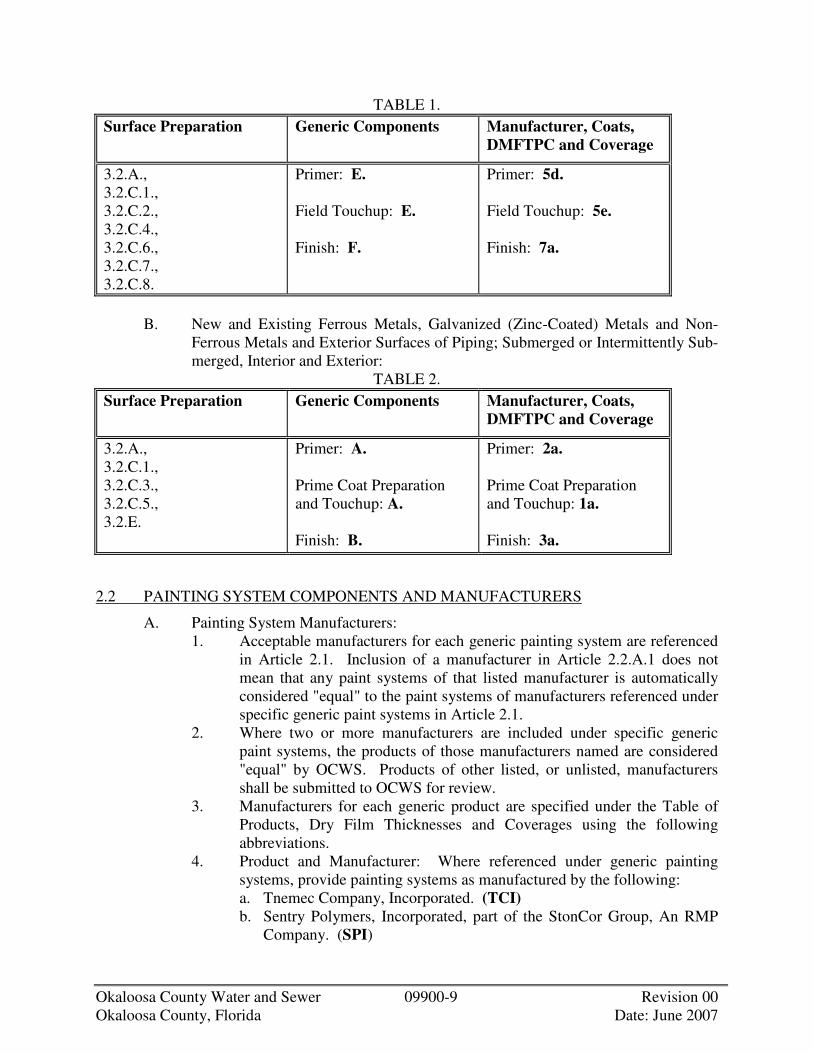
Okaloosa County Water and Sewer 09900-9 Revision 00 Okaloosa County, Florida Date: June 2007
TABLE 1. Surface Preparation Generic Components Manufacturer, Coats,
DMFTPC and Coverage
3.2.A., 3.2.C.1., 3.2.C.2., 3.2.C.4., 3.2.C.6., 3.2.C.7., 3.2.C.8.
Primer: E. Field Touchup: E. Finish: F.
Primer: 5d. Field Touchup: 5e. Finish: 7a.
B. New and Existing Ferrous Metals, Galvanized (Zinc-Coated) Metals and Non-
Ferrous Metals and Exterior Surfaces of Piping; Submerged or Intermittently Sub-merged, Interior and Exterior:
TABLE 2. Surface Preparation Generic Components Manufacturer, Coats,
DMFTPC and Coverage
3.2.A., 3.2.C.1., 3.2.C.3., 3.2.C.5., 3.2.E.
Primer: A. Prime Coat Preparation and Touchup: A. Finish: B.
Primer: 2a. Prime Coat Preparation and Touchup: 1a. Finish: 3a.
2.2 PAINTING SYSTEM COMPONENTS AND MANUFACTURERS
A. Painting System Manufacturers: 1. Acceptable manufacturers for each generic painting system are referenced
in Article 2.1. Inclusion of a manufacturer in Article 2.2.A.1 does not mean that any paint systems of that listed manufacturer is automatically considered "equal" to the paint systems of manufacturers referenced under specific generic paint systems in Article 2.1.
2. Where two or more manufacturers are included under specific generic paint systems, the products of those manufacturers named are considered "equal" by OCWS. Products of other listed, or unlisted, manufacturers shall be submitted to OCWS for review.
3. Manufacturers for each generic product are specified under the Table of Products, Dry Film Thicknesses and Coverages using the following abbreviations.
4. Product and Manufacturer: Where referenced under generic painting systems, provide painting systems as manufactured by the following: a. Tnemec Company, Incorporated. (TCI) b. Sentry Polymers, Incorporated, part of the StonCor Group, An RMP
Company. (SPI)

Okaloosa County Water and Sewer 09900-10 Revision 00 Okaloosa County, Florida Date: June 2007
c. The Carboline Company, part of the StonCor Group, An RMP Company. (TCC)
d. The Sherwin-Williams Company. (SWC) e. E. I. duPont de Nemours & Company. (EID) f. Advanced Polymer Sciences, Incorporated. (APSI) g. California Products Corporation. (CPC) h. Surface Protection Industries, International. (SPII) i. Glidden Company. (GC) j. Benjamin Moore & Company. (BMC) k. Briner-Plasite, part of the StonCor Group, An RMP Company. (BP)
B. Generic Painting System Components: 1. Provide the following generic products as scheduled in Article 2.1 -
Painting Systems:
TABLE OF GENERIC PRODUCTS
A Minimum 56 percent volume solids, high-build, two-component, polyam-
ide-catalyzed epoxy; containing 3.40 pounds per gallon VOC, maximum.
B Minimum 80 percent volume solids, high-build, two-component, cycloali-phatic amine-catalyzed epoxy coating, recommended by manufacturer's product literature as providing the same maximum long-term chemical and corrosion protection as the product series of manufacturer specified; con-taining 1.55 pounds per gallon VOC, maximum.
C. Product Series, Manufacturers, Dry Mil Film Thickness per Coat (DMFTPC), and
Coverage: 1. Provide the following products, manufacturers, and features as scheduled
in Article 2.1 - Painting Systems:
TABLE OF PRODUCTS, DRY FILM THICKNESSES AND COVERAGES
1 Series 66 Hi-Build Epoxoline (TCI); CarboGuard 888 (TCC); Epolon II Multi-Mil Epoxy (SWC): a. 1 coat, 1.5 to 2.5 dry mils, 280-475 square feet per gallon.
2 Series 66 Hi-Build Epoxoline (TCI); CarboGuard 888 (TCC); Macropoxy 646 (SWC): a. 1 coat, 3.0 to 5.0 dry mils, 140-240 square feet per gallon.
3 Series 104 H.S. Epoxy (TCI); Dura-Plate 235 Multi-Purpose Epoxy (SWC): a. 1 coat, 4.0 to 6.0 dry mils, 175-260 square feet per gallon.

Okaloosa County Water and Sewer 09900-11 Revision 00 Okaloosa County, Florida Date: June 2007
PART 3 - EXECUTION
3.1 INSPECTION
A. CONTRACTOR shall examine the areas and conditions under which painting Work is to be performed and notify OCWS in writing of conditions detrimental to the proper and timely completion of the Work. Do not proceed with the Work until unsatisfactory conditions have been corrected in a manner acceptable to OCWS.
B. Do not paint over dirt, rust, scale, grease, moisture, scuffed surfaces, or conditions otherwise detrimental to the formation of a durable paint film capable of performing in accordance with claims made in manufacturer's product literature for the surfaces and conditions encountered.
C. Do not paint over existing paint where there is no assurance that existing paint will provide an acceptable surface for the long-term adherence and durability of painting systems specified or where the manufacturer requires removal of all existing paint in order to recommend the use of the specified painting system.
3.2 SURFACE PREPARATION
A. General: 1. Perform all preparation and cleaning procedures as specified herein and in
strict accordance with paint manufacturer's approved instructions for each particular surface and atmospheric condition.
2. CONTRACTOR shall remove, as necessary, items, which must be field-painted where adjacent surfaces cannot be completely protected from splatter or overspray. Following completion of painting of each space or area, the removed items shall be reinstalled by workers skilled in the trades involved.
3. Clean surfaces to be painted before applying any painting system components. Remove oil and grease with clean cloths and cleaning solvents prior to mechanical cleaning.
4. Prepare all surfaces which were improperly shop-painted, and all abraided or rusted shop-painted surfaces, as specified.
3.3 ADJUSTMENT AND CLEAN-UP
A. Correct all damages to the work by cleaning, repairing or replacing, and repainting, as acceptable to OCWS.
B. During the progress of the Work, remove from the Site all discarded paint materials, rubbish, cans and rags at the end of each work day.
C. Upon completion of painting, clean all paint-spattered surfaces. Remove spattered paint by proper methods of washing and scraping, using care not to scratch or otherwise damage finished surfaces.
D. At the completion of Work, touch-up and restore all damaged or defaced painted surfaces.

OKALOOSA COUNTY WATER AND SEWER
DIVISION 11
Okaloosa County Water and Sewer Revision 00 Okaloosa County, Florida Date: June 2007
DIVISION 11 EQUIPMENT
SECTION 11145 LIFT STATION SPECIFICATIONS


Okaloosa County Water and Sewer 11145-1 Revision 00 Okaloosa County, Florida Date: June 2007
SECTION 11145
LIFT STATION SPECIFICATIONS
PART 1 - GENERAL
1.1 DESCRIPTION
A. General Requirements: 1. As-Built Records:
a. A complete set of As-Built records shall be kept by the Contractor. These records shall show all items of construction and equipment which differ in size, shape or location from those shown on the contract drawings, also any additional work, existing features or utilities revealed by construction work which are not shown on the contract drawings. These reports shall be kept up-to-date daily. They may be kept on a marked set of contract drawings to be furnished by the contractor for this purpose, or in any other form, which is approved prior to the beginning of the work. They shall be available at all times during construction for reference by the Engineer and Owner, and shall be delivered to the OCWS Engineering Department upon completion of the work.
2. Nameplate: a. Each piece of mechanical equipment and motors shall be provided
with a substantial nameplate of non-corrodible metal securely fastened in place, and clearly and permanently inscribed with the manufacturer's name, model, or type designation, serial number, rated capacity, electrical or other power characteristics, and other appropriate nameplate data. Spare nameplates shall be provided for each lift station and placed inside each control panel (one nameplate for each model pump).
3. Lubricants: a. All the equipment shall be delivered fully lubricated with oil and/or
grease insofar as possible. If any point cannot be so serviced, it shall be clearly marked to the effect that it is not lubricated and requires servicing prior to operation. An adequate supply of the proper lubricant, with the instructions for its application shall be supplied with the equipment for each point not lubricated prior to shipment. The Contractor shall also provide the Owner with a sufficient amount of proper lubricants for one complete change of lubricant for all equipment furnished.
4. Operating Manuals and Parts Listed: a. The Contractor shall furnish three (3) complete, bound sets of
literature giving the following information to the Okaloosa County Water and Sewer Engineering Department.

Okaloosa County Water and Sewer 11145-2 Revision 00 Okaloosa County, Florida Date: June 2007
1) Clear and Concise instruction for operations, adjustment and lubrication and other of the equipment. These instructions shall include a complete lubrication chart.
2) A list of all parts of the equipment, with catalog number and other data necessary for ordering replacement parts.
3) Such instructions and parts listed shall have been prepared specifically for the model and type of equipment furnished and shall not refer to other models and types of similar equipment.
4) Complete sets of electrical schematic(s), (as built) one of which shall be encapsulated in plastic and permanently mounted to the inside of lift station door.
5. Telemetry Equipment: a. A telemetry fee shall be paid to:
1) Okaloosa County Water and Sewer System 2) 1804 Lewis Turner Boulevard, Suite 300 3) Fort Walton Beach, Florida 32547
4) This fee will cover the expense of installing telemetry equipment,
at the time of purchasing other associated connection cost. 6. Fencing:
a. Fence specifications will vary, subject to the requirements of the developer and the Okaloosa County Water and Sewer System.
7. Force Main (Thermoplastic Pipe): a. A #14 copper insulated tracer wire shall be laid over the full length of
the force main. Refer to Section 3556 for force main specifications. 8. Water Service:
a. A ¾" Potable water service shall be made available at Lift Station Site.
PART 2 - PRODUCTS
2.1 MATERIALS
A. Valve Housing Box: 1. The exterior of the valve housing box shall be water proofed by the
manufacturer with two coats of Kopper’s Bitumastic 300-M pr approved equal type sealant to prevent ground water infiltration.
2. The interior of the valve housing box shall have a smooth plastered finish, bottom section to be sloped to one corner.
3. There shall be a minimum of 18" clearance on all sides of valves and fittings.
4. The check valves shall be a waffer swing check valve with external lever and spring as manufactured by Empire Specialty Co. Inc., or approved equal. Cast Iron Body, renewable Buna N Seal, and AWWA C115 Flanged connection. The shaft, center pin, disc arm set screw, seat screws

Okaloosa County Water and Sewer 11145-3 Revision 00 Okaloosa County, Florida Date: June 2007
and disc arm key shall be stainless steel. 5. All exposed hardware shall be of corrosion resistant, stainless steel. 6. The Access Hatches shall be aluminum double-door type, rated at 300
lb/sq. ft. A minimum of 3' x 3' overall, mounted and centered on the box as shown on the drawings. Doors shall be of skid-proof design.
7. All valve housing boxes shall be a solid cast in place or precast concrete box with bottom grouting of box bottom not permitted.
8. The gate valves shall be AWWA C509 Compression Resilient Seated, Flanged Cast Iron Body with epoxy coated interior, and manual handwheel actuator.
9. An emergency by-pass gate valve with an Ever-tite Quick Coupling, Part "F", Male adaptor with male thread, 4" aluminum, shall be used, and installed within the valve box proceeding the in-line check and gate valve. The coupling should be located in a manner that it is accessible when the access hatch is open, with no obstructions so that a 4" suction hose can be easily attached for emergency operations.
B. Wet Well: 1. There shall be stainless steel pull cables fastened with stainless steel
clamps to the lift rings on each pump. The top end of the cable shall have a minimum of 4" loop fastened with stainless steel clamps. The cable shall be of adequate strength to permit raising and lowering of the pumps.
2. The entire internal discharge riser pipes shall be scheduled 80 P.V.C. joined with schedule 80 P.V.C. cement.
3. A double door aluminum access frame and cover, rated at 300 lb/sq. ft., complete with hinged and flush locking mechanism, 316 S.S. upper guide holder and level sensor(s) cable holder shall be furnished and installed on the pump station wet well. Frame shall be securely placed, mounted above the pumps. Frame shall be provided with sliding nut rails to attach the accessories required. Lower guide bar holders shall be integral with the discharge connection. Guide bars shall be of at least 316 stainless steel pipe. Doors shall be of skid proof design.
4. All lift eyes within the interior and exterior of wet well shall be cut off flush with the existing surface, and sealed with a Bitumastic type sealant.
5. Steps will not be allowed inside the wet well. 6. Schedule 80 PVC with a flange on each end shall be used from the
exterior of the wet well into the valve box. 7. The discharge piping shall be intermediately supported inside the wet well
by the use of a stainless steel uni-strut bolted to the well wall, and stainless steel u-bolts and clamps secured to the discharge pipe and strut.
8. All fasteners inside wet well shall be 316 stainless steel. 9. Hatch to Wet Well shall be as a minimum 4' x 4' in size or larger, as
specified on plans. 10. Wet Well shall be 6' diameter or larger or 6' x 6' square or larger as
specified on plans. 11. A guide rail system for pump removal shall be installed inside the wet

Okaloosa County Water and Sewer 11145-4 Revision 00 Okaloosa County, Florida Date: June 2007
well for each pump. The guide rails shall be of at least 316 stainless steel pipe of the size indicated on the drawing, but a minimum of two (2") inches in diameter. The guide bars shall not support any portion of the weight of the pump. The lower guide bracket shall be incorporated and tightly secured to the discharge connection elbow with 316 stainless steel fasteners. The entire slide rail system shall conform to Underwriters Laboratory (U. L.) requirements, for use in Class I, Division I, Group D environments.
12. Ductile iron influent piping shall be coated with Protecto 401. C. Alternate Wet Well/Valve Box:
1. Stand alone Fiberglass Structures may be used for Wet Well and Valve Pit. The FRP structures must meet and or exceed ASTM-D3753 standards. The structures must be Third Party Tested and Certified to meet the ASTM-D3753 standards. A copy of this certification must be provided with Submittal Data. Manufacturers that do not have this Third Party Certification included with the submittal data will not be approved. The structures must have labels that have serial numbers visible and states the manufacturer, date of manufacture, depth, diameter, and that structure meets ASTM-D3753 standards. If the Manufacturer is contacted they must be able to state purchaser, diameter, depth, and date that the wet well was purchased simply by providing the serial numbers. Manufacturers that do not maintain files that track serial numbers will not be accepted as warranties will not be verifiable.
2. The fiberglass structures must have a standard 10 Year structural warranty. The fiberglass structures must have a printed 10 Year warranty label gel coated next to ASTM and serial number label. Copy of this warranty must be included with the submittal data. Approved Manufacturer is L.F. Manufacturing, Giddings, Texas (www.lfm-frp.com).
3. Wet wells/Valve Pits shall have 12” risers with “Drop In” Aluminum Hatch Cover. Upon completion the wet well and valve pit shall have an 8” concrete slab poured over top. On wet wells 8’ in diameter or larger an extra hatch cover shall be supplied on opposite side of wet well to allow installation of future equipment.
4. The wet well shall include guide rail systems with SST components and fiberglass I-Beams or dual SST pipe for slide rails. The basis of design for the guide rail system is Hydromatic Pump’s Pultruded/MTM Rail System. The base elbow and sealing flange shall be constructed of Cast Iron.
5. Valve pit shall include two (2) epoxy coated swing check valves with outside lever and spring, three (3) full port SST plug valves (By American), Emergency pump out connection with dust cap and all the necessary gaskets, straight pipe, brackets, elbows, tees, and fittings. Minimum valves and pipe size shall be 4”.
6. All piping will be Sch. 40 SST for corrosion resistance and strength. Where piping passes through a wall sleeves shall be used with rubber link seals to make a watertight penetration. The sleeves must be large enough

Okaloosa County Water and Sewer 11145-5 Revision 00 Okaloosa County, Florida Date: June 2007
for flange of pipe being used to pass freely through (Example: 4” pipe would require a 10” sleeve to allow 9-1/2” O.D. diameter of 4” flange). The link seals are used so that the rubber acts as vibration isolator while pump is running.
7. All piping in wet well and valve pit shall be welded Flange X Flange Sch. 40 SST. Hardware used for connections must be SST bolts with Brass nuts.
8. Discharge piping in wet well must have “air release” valves (Waterman type, or equal).
9. Oil filled pressure gauges rated for 1-1/2 times specified pumping pressures with ¾” SST ball valves must be provided for each discharge. Gauges must be located between check and plug valve so that static head can be observed when pump is off, TDH can be observed while pumps are running, and plug valves can be shut to observe “dead head” pressure.
10. The Emergency Pump Out Connection Dust Cap must be tapped with ¼” pet cock so as to bleed off any accumulated pressure that may build up prior to removing cap.
D. Plates, Sheets, and Shapes: 1. Aluminum Plates, Sheets and Shapes:
a. All aluminum plates and shapes shall be of type AA 5052 alloy conforming to applicable requirements of ASTM Designation B 209-67, (latest revision).
b. Aluminum extended shapes shall be 6061 or 6062 alloy conforming to ASTM B 221-67, (latest revision).
c. All surfaces in contact with concrete shall be coated with Bitumastic (Kopper's 50 or equal).
2. Stainless Steel Plates, Sheets, and Shapes: a. All stainless steel plates and sheets shall be type 316 alloy conforming
to the applicable requirements of ASTM Designation A-182, (latest revision).
b. Stainless Steel pipe shall be schedule 5, Type 316 alloy conforming to the applicable requirements of ASTM-312, (latest revision).
3. Fastenings: a. Fasteners insofar as practical shall be concealed. Where exposed,
fastening shall be of 316 stainless steel, where not indicated otherwise and countersunk wherever possible.
b. All fastenings coming into contact with aluminum and /or submerged shall be of stainless steel.
c. All hardware used to assemble ductile iron fittings shall be stainless steel. Threads shall be coated with antiseize compound.
d. All threaded fasteners to include threaded rods shall be coated with antiseize compound.
E. Submersible Pumping Equipment: 1. Pumps:
a. Pumps shall be submersible, heavy duty, recessed impeller type or an

Okaloosa County Water and Sewer 11145-6 Revision 00 Okaloosa County, Florida Date: June 2007
approved equal by the Okaloosa County Water & Sewer Engineering Department.
b. The pumps shall be capable of handling raw, unscreened sewage. The discharge connection elbow shall be permanently installed in the wet well along with the discharge piping. The pumps shall be automatically connected to the discharge connection elbow when lowered into place, and shall be easily removed for inspection or service. There shall be no need for personnel to enter pump well. Sealing of the pumping unit to the discharge connection elbow shall be accomplished by the simple linear downward force of the pump. A sliding guide bracket shall be an integral part of the pump unit. The entire weight of the pump unit shall be guided by no less than two guide bars and pressed tightly against the discharge connection elbow with metal-to-metal contact by gravity only. Sealing of the discharge interface by means of a diaphragm, O-ring, or other devices will not be acceptable. No portion of the pump shall bear directly on the floor of the wet well. The pump, with its appurtenances and cable, shall be capable of continuous submergence underwater, without loss of water-tight integrity to a depth of 65 ft. Totally submersible design, with all electrical parts housed in an air-filled cast-iron, water tight enclosure. Thrust and radial bearings shall be of the ball type. The motor shafting shall be stainless steel and designed for extremely difficult sewage pumping service. The motor shall be designed to operate on 3-phase, 60-cycle, 240 volt alternating current and shall be non-overloading at all points on the pump curve.
2. Manufacturing: a. The duplex submersible pumps shall be as manufactured by
Hydromatic, ESSCO, Davis EMU, Wemco, or an approved equal by the Okaloosa County Water & Sewer Engineering Department. Submittal data required before approval if equal is requested.
3. Submittal Data: a. The contractor shall provide three (3) copies of the following submittal
data for each item of pumping equipment: 1) Certified Dimensional Print 2) Typical Performance Curve 3) Pictorial and Schematic Wiring Prints 4) Parts Listed and Instructional Prints 5) Pump Components and Warranty.
4. Pump Characteristics: a. Pumps shall furnish the following:
1) Pump to pass minimum sphere of 3½" diameter. 2) Minimum motor size, 5 HP, unless otherwise approved by OCWS
Engineering. 3) Recessed impellar unless otherwise approved by the OCWS
Engineering Department.

Okaloosa County Water and Sewer 11145-7 Revision 00 Okaloosa County, Florida Date: June 2007
5. Controls: a. Automatic control of the duplex submersible pumps shall be by means
of a system of sealed mercury float switches of compressed air. The switch shall by capable of starting and stopping the pumps at an adjustable differential, starting the lead pump first and then the lag pump if wet well level continues to rise, running both pumps simultaneously and automatic alternation of the lead and lag pumps. The control shall be housed in a Stainless Steel NEMA Standard 250, Type 4x enclosure with a pad lock hasp. The enclosure shall include: 1) Dead front enclosure made of stainless steel. 2) Two (2) motor starters of adequate size. 3) 120-Volt, 20-Amp duplex receptacle. 4) Four (4) circuit breakers, one for each pump, one for the receptacle
and one for the control circuitry. 5) Two (2) HOA (hand-off automatic) switches. 6) Three (3) pole overload relay with one (1) heater per pole for each
pump. 7) Pump alternating circuit. 8) 24 Volt Ac or 120 Volt AC Control Voltage.(120 V AC preferred) 9) Two (2) run lights (green), run light shall be clearly labeled. 10) Two (2) moisture detection relays and yellow warning lights. 11) Two (2) 0 to 99,999.9 hour elapsed time meters. 12) Phase Failure relay required (plug-in type, 8-pin). 13) A minimum of 12" x 12" shall be vacant on inside of sub panel for
additional equipment. 14) A high level float switch will be provided and wired to a terminal
strip in the panel. 15) A 110-Volt exterior flood light, 175 wattage rating, with a remote
switch installed inside the main control panel, shall be mounted adjacent to and overhead of the panel and wet well.
16) A motor over-temp circuitry shall be installed, so that if the motor reaches an over-temp condition, the control voltage to that motor is interrupted. This shall illuminate a red warning light in the panel.
17) The controller shall be completely assembled, tested and ready for operation prior to final acceptance inspection.
6. Alternate Control Systems: a. Alternate control systems and arrangements will be considered
provided all functional characteristics are met. 7. Electrical:
a. General: 1) All electrical equipment shall be installed in accordance with the
N.E.C. Code, as last revised. All materials used shall be new and unused, of the highest quality, and of proper type for the use intended. Where applicable, all material shall carry the approval of the Underwriters' Laboratory. Substitutes, which tend to lower the quality of the work, will not be permitted. The project is to result

Okaloosa County Water and Sewer 16600-8 Revision 00 Okaloosa County, Florida Date: June 2007
in a complete and operable Lift Station. Any items not specified, but normally included in such installations shall be finished and installed regardless of omissions from specifications. However, specified omissions are not affected by this requirement. The electrical service and starting gear shall be mounted on a suitably sized panel frame constructed of aluminum 4" x 4" x ¼" angle or galvanized steel uni-strut material. All details of service characteristics shall be verified with the local utility.
8. Materials: a. Conduit and conduit fittings shall be P.V.C. Electrical connectors and
couplings shall be of the approved plastic water-tight type. b. Wire and cable shall be properly sized to carry the anticipated loading.
Insulation, unless otherwise noted, shall be typed RHW neoprene jacket for all sizes.
c. Conduit into wet well shall be large enough for easy removal of pump leads and/or float leads but as a minimum 1½" diameter. There shall be one conduit for each pump, plus one for float switch cables if used.
9. Installations: a. All conduit runs, whether or not terminated in boxes, shall be capped
or plugged to prevent the entrance of foreign objects before wires are pulled. Conduit projecting into the wet well shall be plugged to a depth no more than 2" from the control panel with non-hardening compound, after the wires are pulled to prevent corrosive gases from reaching the control panel. Compound should be easily removed for removal\replacement of wiring.
b. Outlets, switches, boxes, etc., shall be rigidly secured and located properly with respect to easy accessibility.
c. No electrical splices allowed except in control panel. d. All work shall be tested and subject to final approval of the engineer.
10. Stand-by Facilities: a. A double throw safety switch suitable sized to carry the operating
current of the station with attached emergency generator receptacle shall be installed between the main disconnect and the controller. The unit shall be housed in a NEMA 3R painted steel enclosure. The receptacle shall be a Crouse-Hinds, rated for 100-Amp, larger as required. A 45 degree angle adapter is recommended to allow for easier generator connection, and to prevent water intrusion.
11. Lightning Arrestor: a. The lightning arrestor for the main service entrance shall be Joshlin or
approved equal. 12. Main Disconnect:
a. The main disconnect safety switch shall be an enclosed service entrance, weather-proof enclosure, 4 wire S/N, 240/480 Volt AC of sufficient size to carry both pumps operating simultaneously.
THESE SPECIFICATIONS ARE SUBJECT TO CHANGE.

OKALOOSA COUNTY WATER AND SEWER
DIVISION 15
Okaloosa County Water and Sewer Revision 00 Okaloosa County, Florida Date: June 2007
DIVISION 15 MECHANICAL
SECTION 15051 BURIED PIPING INSTALLATION SECTION 15052 EXPOSED PIPING INSTALLATION SECTION 15100 VALVES, 4-INCH AND LARGER


Okaloosa County Water and Sewer 15051-1 Revision 00 Okaloosa County, Florida Date: June 2007
SECTION 15051
BURIED PIPING
PART 1 - GENERAL
1.1 DESCRIPTION
A. Scope: 1. CONTRACTOR shall provide all labor, materials, equipment and
incidentals as shown, specified and required to install and test all buried piping, fittings, and specials. The Work includes, but is not limited to, the following: a. All types and sizes of buried piping, except those specified under other
Sections or other contracts. b. Piping beneath structures. c. Supports, restraints, and thrust blocks. d. Pipe encasements. e. Work on or affecting existing piping. f. Testing. g. Cleaning and disinfecting. h. Installation of all jointing and gasketing materials, specials, flexible
couplings, mechanical couplings, harnessed and flanged adapters, sleeves, tie rods, and all other Work required to complete the buried piping installation.
i. Incorporation of valves, meters and special items shown or specified into the piping systems as required and as specified in the appropriate Division 15 Sections.
j. Unless otherwise specifically shown, specified, or included under other Sections, all buried piping Work required, beginning at the outside face of structures or structure foundations and extending away from structure.
B. Coordination: 1. Review installation procedures under other Sections and other contracts
and coordinate with the Work that is related to this Section. 2. Section 15051 specifies the installation of all buried piping materials
specified in Section 15052. Coordinate with this Section. C. Related Sections:
1. Section 02220, Excavation and Backfill. 2. Section 03300, Cast-In-Place Concrete. 3. Section 09900, Painting. 4. Division 15, Sections on Piping, Valves and Appurtenances.

Okaloosa County Water and Sewer 15051-2 Revision 00 Okaloosa County, Florida Date: June 2007
1.2 QUALITY ASSURANCE
A. Requirements of Regulatory Agencies: 1. Comply with requirements of NFPA Standard No. 24 for "Outside
Protection" where applicable to water pipe systems used for fire protection.
2. Comply with requirements of UL, FM and other jurisdictional authorities, where applicable.
3. Refer to the General and Supplementary Conditions regarding permit requirements for this Project.
B. Reference Standards: Comply with applicable provisions and recommendations of the following, except as otherwise shown or specified. 1. ASTM D 2321, Practice for Underground Installation of Flexible
Thermoplastic Sewer Pipe. 2. ASTM D 2774, Practice for Underground Installation of Thermoplastic
Pressure Piping. 3. AWWA C105, Polyethylene Encasement for Ductile-Iron Piping for
Water and Other Liquids. 4. AWWA C111, Rubber-Gasket Joints for Ductile-Iron Pressure Pipe and
Fittings. 5. AWWA C600, Installation of Ductile-Iron Water Mains and Their
Appurtenances. 6. AWWA C606, Grooved and Shouldered Joints. 7. AWWA C651, Disinfecting Water Mains. 8. AWWA M23, PVC - Design and Installation. 9. ASCE MOP No. 37, Design and Construction of Sanitary and Storm
Sewers. 10. NFPA 24, Private Fire Service Mains and Their Appurtenances.
1.3 SUBMITTALS
A. Shop Drawings: Submit for approval the following: 1. Full details of piping, specials, manholes, joints, harnessing and thrust
blocks, and connections to existing piping, structures, equipment and appurtenances.
B. Tests: Submit description of proposed testing methods, procedures and apparatus. Prepare and submit report for each test.
C. Certificates: Submit certificates of compliance with referenced standards. D. Record Drawings:
1. Submit record drawings prior to the time of Substantial Completion.
1.4 PRODUCT STORAGE AND HANDLING
A. Handle all pipe, fittings, specials and accessories carefully with approved handling devices. Do not drop or roll material off trucks. Do not otherwise drop, roll or skid piping.

Okaloosa County Water and Sewer 15051-3 Revision 00 Okaloosa County, Florida Date: June 2007
B. Store pipes and fittings on heavy wood blocking or platforms so they are not in contact with the ground.
C. Unload pipe, fittings and specials opposite to or as close to the place where they are to be installed as is practical to avoid unnecessary handling. Keep pipe interiors completely free from dirt and foreign matter.
D. Inspect delivered pipe for cracked, gouged, chipped, dented or other damaged material and immediately remove from site.
PART 2 - PRODUCTS
2.1 MATERIALS
A. Approved pipe materials are listed in the Piping Schedule. Refer to applicable Sections for material specifications.
B. General: 1. Marking Piping:
a. Clearly mark each piece of pipe or fitting with a designation conforming to those shown on the laying schedule.
b. Cast or paint material, type and pressure designation on each piece of pipe or fitting 4 inches in diameter and larger.
c. Pipe and fittings smaller than 4 inches in diameter shall be clearly marked by manufacturer as to material, type and rating.
PART 3 - EXECUTION
3.1 INSTALLATION
A. General: 1. Install piping as shown, specified and as recommended by the
manufacturer. 2. If there is a conflict between manufacturer's recommendations and the
Drawings or Specifications, request instructions from OCWS before proceeding
3. All trench excavations shall be inspected by OCWS prior to laying pipe. Notify OCWS in advance of excavating, bedding and pipe laying operations.
4. Minimum cover over piping shall be 3 feet unless otherwise shown or approved by OCWS.
5. Earthwork required is specified in the applicable Sections of Division 2. 6. Excavation in excess of that required or shown and which is not
authorized by OCWS shall be replaced at CONTRACTOR'S expense with approved granular material. It shall be furnished, placed and compacted in accordance with the requirements of the applicable Section of Division 2.

Okaloosa County Water and Sewer 15051-4 Revision 00 Okaloosa County, Florida Date: June 2007
B. Manufacturer's Installation Specialist: 1. Provide the services of a competent installation specialist of the pipe
manufacturer when pipe laying commences for the following: a. Thermoplastic pipe.
2. Retain installation specialist at the site until competency of the pipe laying crew has been satisfactorily demonstrated.
C. Separation of Sewers and Potable Water Pipe Lines: 1. Horizontal and Vertical Separation:
a. Wherever possible, existing and proposed potable water mains and service lines, and sanitary and storm sewers shall be separated horizontally by a clear distance of not less than 10 feet.
b. If local conditions preclude a clear horizontal separation of not less 10 feet, the installation will be permitted provided the potable water main is in a separate trench or on a undistributed earth shelf located on one side of the sewer and at an elevation so the bottom of the potable water main is at least 18 inches above the top of the sewer.
c. Exception: 1) Where it is not possible to provide the minimum horizontal and
vertical separation described above, both the potable water main and sewer must be constructed of cement lined ductile iron slip-on or mechanical joint pipe complying with public water supply design standards of the agency. Both pipes shall be pressure tested in accordance with the requirements of the buried piping schedule, but in no case less than 150 psi, to assure water tightness before backfilling.
2. Crossings: a. Provide a minimum vertical distance of 18 inches between the outside
of the potable water main and the outside of the sewer when a sewer or drain must cross over a potable water main.
b. Center one full length section of potable water main over the sewer so that the sewer joints will be equidistant from the potable water main joints.
c. Provide adequate structural support where a potable water main crosses under a sewer to maintain line and grade.
d. Exceptions: 1) Where it is not possible to provide the minimum horizontal and
vertical separation described above, both the potable water main and sewer must be constructed of cement lined ductile iron pipe. Both pipes shall be pressure tested in accordance with the requirements of the buried piping schedule, but in no case less than 150 psi, to assure water tightness before backfilling.
2) Encase either potable water main or sewer in a watertight carrier pipe, which extends 10 feet on both sides of the crossing, measured perpendicular to the potable water main.
D. Plugs:

Okaloosa County Water and Sewer 15051-5 Revision 00 Okaloosa County, Florida Date: June 2007
1. Temporarily plug installed pipe at the end of each day's work or other interruption to the installation of any pipe line. Plugging shall prevent the entry of animals, liquids or persons into the pipe or the entrance or insertion of deleterious materials.
2. Install standard plugs into all bells at dead ends, tees or crosses. Cap all spigot ends.
3. Fully secure and block all plugs and caps installed for pressure testing to withstand the specified test pressure.
4. Where plugging is required for phasing of the Work or for subsequent connection of piping, install watertight, permanent type plugs.
E. Bedding Pipe: Bed pipe as specified below and in accordance with the details shown. 1. Trench excavation and backfill, and bedding materials shall conform to
the requirements of Section 02200, as applicable. 2. Where the existing bedding material is deemed unsuitable by OCWS,
remove and replace it with approved granular materials. 3. Where pipe is installed in rock excavation, provide a minimum of 3 inches
of crushed stone or gravel under pipes smaller than 4 inches in diameter and a minimum of 6 inches of crushed stone or gravel under pipes 4 inches in diameter and larger.
4. Excavate trenches below the pipe bottom by an amount shown and specified. Remove all loose and unsuitable material from the trench bottom.
5. Carefully and thoroughly compact all pipe bedding with hand held pneumatic compactors.
6. Do not lay pipe until OCWS approves the bedding condition. If a conflict exists obtain clarification from OCWS before proceeding.
7. No pipe shall be brought into position until the preceding length has been bedded and secured in its final position.
F. Laying Pipe: 1. Conform to manufacturer's instructions and requirements of the standards
listed below, where applicable: a. Ductile Iron Pipe: AWWA C600, AWWA C105. b. Thermoplastic Pipe: ASTM D 2774. c. ASCE Manual of Practice No. 37.
2. Install all pipe accurately to line and grade shown unless otherwise approved by OCWS. Remove and relay pipes that are not laid correctly.
3. Slope piping uniformly between elevations shown. 4. Ensure that ground water level in trench is at least 6 inches below bottom
of pipe before laying piping. Do not lay pipe in water. Maintain dry trench conditions until jointing and backfilling are complete and protect and keep clean water pipe interiors, fittings and valves.
5. Start laying pipe at lowest point and proceed towards the higher elevations, unless otherwise approved by OCWS.
6. Place bell and spigot pipe so that bells face the direction of laying, unless otherwise approved by OCWS.

Okaloosa County Water and Sewer 15051-6 Revision 00 Okaloosa County, Florida Date: June 2007
7. Excavate around joints in bedding and lay pipe so that the barrel bears uniformly on the trench bottom.
8. Deflections at joints shall not exceed 75 percent of the amount allowed by the pipe manufacturer.
9. For thermoplastic piping, snake piping in trench to compensate for thermal expansion.
10. Carefully examine all pipe, fittings and specials for cracks, damage or other defects while suspended above the trench before installation. Immediately remove defective materials from site.
11. Inspect interior of all pipe and fittings and completely clean all dirt, gravel, sand, debris or other foreign material from pipe interior and joint recesses before it is moved into the trench. Bell and spigot mating surfaces shall be thoroughly wire brushed, and wiped clean and dry immediately before the pipe is laid.
12. Field cut pipe, where required, with a machine specially designed for cutting piping. Make cuts carefully, without damage to pipe or lining, and with a smooth end at right angles to the axis of pipe. Cut ends on push-on joint shall be tapered and sharp edges filed off smooth. Flame cutting will not be allowed.
13. Blocking under piping will not be permitted unless specifically approved by OCWS for special conditions. If permitted, conform to requirements of AWWA C600.
14. Touch up protective coatings in a satisfactory manner prior to backfilling. 15. CONTRACTOR shall notify OCWS in advance of backfilling operations. 16. On steep slopes, take measures acceptable to OCWS to prevent movement
of the pipe during installation. 17. Thrust Restraint: During the installation of the pipe, thrust blocks, tied
joints, or proprietary restrained joint systems shall be provided wherever required for thrust restraint. Thrust restraint shall conform to the applicable requirements of Article 3.2.
G. Polyethylene Encasement: 1. Provide polyethylene encasement for ductile iron piping to prevent contact
between the pipe and surrounding bedding material and backfill. 2. Polyethylene may be supplied in tubes or in sheet material. 3. Polyethylene encasement materials and installation shall be in accordance
with the requirements of AWWA C105. H. Jointing Pipe:
1. Ductile Iron Mechanical Joint Pipe: a. Wipe clean the socket, plain end and adjacent areas immediately
before making joint. Make certain that cut ends are tapered and sharp edges are filed off smooth.
b. Lubricate the plain ends and gasket with soapy water or an approved pipe lubricant, in accordance with AWWA C111, just prior to slipping the gasket onto the plain end of the joint assembly.

Okaloosa County Water and Sewer 15051-7 Revision 00 Okaloosa County, Florida Date: June 2007
c. Place the gland on the plain end with the lip extension toward the plain end, followed by the gasket with the narrow edge of the gasket toward the plain end.
d. Insert the pipe into the socket and press the gasket firmly and evenly into the gasket recess. Keep the joint straight during assembly.
e. Push gland toward socket and center it around pipe with the gland lip against the gasket.
f. Insert bolts and hand tighten nuts. g. Make deflection after joint assembly, if required, but prior to
tightening bolts. Alternately tighten bolts 180 degrees apart to seat the gasket evenly. The bolt torque shall be as follows:
Pipe Size Bolt Size Range of Torque (inches) (inches) (ft-lbs)
3 5/8 45-60
4-24 3/4 75-90 30-36 1 100-120 42-48 1-1/4 120-150
2. Ductile Iron Push-On Joint Pipe:
a. Prior to assembling the joints, the last 8 inches of the exterior surface of the spigot and the interior surface of the bell shall be thoroughly cleaned with a wire brush, except where joints are lined or coated with a special protective lining or coating.
b. Rubber gaskets shall be wiped clean and flexed until resilient. Refer to manufacturer's instructions for procedures to ensure gasket resiliency when assembling joints in cold weather.
c. Insert gasket into joint recess and smooth out the entire circumference of the gasket to remove bulges and to prevent interference with the proper entry of the spigot of the entering pipe.
d. Immediately prior to joint assembly, apply a thin film of approved lubricant to the surface of the gasket, which will come in contact with the entering spigot end of pipe. CONTRACTOR may, at his option, apply a thin film of lubricant to the outside of the spigot of the entering pipe.
e. For assembly, center spigot in the pipe bell and push pipe forward until it just makes contact with the rubber gasket. After gasket is compressed and before pipe is pushed or pulled all the way home, carefully check the gasket for proper position around the full circumference of the joint. Final assembly shall be made by forcing the spigot end of the entering pipe past the rubber gasket until it makes contact with the base of the bell. When more than a reasonable amount of force is required to assemble the joint, the spigot end of the pipe shall be removed to verify the proper positioning of the rubber

Okaloosa County Water and Sewer 15051-8 Revision 00 Okaloosa County, Florida Date: June 2007
gasket. Gaskets, which have been scoured or otherwise damaged, shall not be used.
f. Maintain an adequate supply of gaskets and joint lubricant at the site at all times when pipe jointing operations are in progress.
3. Proprietary Joints: a. Pipe which utilizes proprietary joints such as Fastite, by American
Cast Iron Pipe Company, Tyton by U.S. Pipe Incorporated, restrained joints described under Paragraph 3.2.D., or other such joints shall be installed in strict accordance with the manufacturer's instructions.
4. Flanged Joints: a. Assemble flanged joints using 1/8-inch ring-type gaskets for raised
face flanges. Use full face gaskets for flat face flanges, unless otherwise approved by OCWS. Gaskets shall be suitable for the service intended in accordance with the manufacturer's ratings and instructions. Gaskets shall be properly centered.
b. Bolts shall be tightened in a sequence, which will insure equal distribution of bolt loads.
c. The length of bolts shall be uniform, and they shall not project beyond the nut more than 1/4-inch or fall short of the nut when fully taken up. The ends of bolts shall be machine cut so as to be neatly rounded. No washers shall be used.
d. Bolt threads and gasket faces for flanged joints shall be lubricated prior to assembly.
e. After assembly, coat all bolts and nuts with two 8-mil coats of a high-build epoxy or bituminous coating as manufactured by Tnemec, or equal.
5. Thermoplastic Pipe Joints: a. Solvent Cement Joints:
1) Bevel pipe ends and remove all burrs before making joints. Clean both pipe and fittings thoroughly. Do not attempt to make solvent cement joints if temperature is below 40 F nor in wet conditions.
2) Use solvent cement supplied or recommended by the pipe manufacturer.
3) Apply joint primer and solvent cement and assemble joints in strict accordance with the recommendations and instructions of the manufacturer of the joint materials and the pipe manufacturer.
4) Observe safety precautions with the use of joint primers and solvent cements. Allow air to circulate freely through pipelines to permit solvent vapors to escape. Slowly admit water when flushing or filling pipelines to prevent compression of gases within pipes.
b. Push-On Joints: 1) Bevel all field-cut pipe, remove all burrs and provide a reference
mark the correct distance from the pipe end. 2) Clean the pipe end and the bell thoroughly before making the joint.
Insert the O-ring gasket, making certain it is properly oriented.

Okaloosa County Water and Sewer 15051-9 Revision 00 Okaloosa County, Florida Date: June 2007
Lubricate the spigot well with an approved lubricant; do not lubricate the bell or O-ring. Insert the spigot end of the pipe carefully into the bell until the reference mark on the spigot is flush with the bell.
I. Backfilling: 1. Conform to the applicable requirements of Section 02220 or 02223. 2. Place backfill as construction progresses. Backfill by hand and use power
tampers until pipe is covered by at least one foot of fill. J. Connections to Valves and Hydrants:
1. Install valves and hydrants as shown. 2. Provide suitable adapters when valves or hydrants and piping have
different joint types. 3. Provide thrust restraint at all hydrants and at valves at pipeline
terminations. K. Transitions from One Type of Pipe to Another:
1. Provide all necessary adapters, specials and connection pieces required when connecting different types and sizes of pipe or connecting pipe made by different manufacturers.
L. Closures: 1. Provide all closure pieces shown or required to complete the Work.
3.2 THRUST RESTRAINT
A. Provide thrust restraint on all pressure piping systems and where otherwise shown and specified.
B. Thrust restraint may be accomplished by means of restrained pipe joints, or by concrete thrust blocks. Thrust restraints shall be designed for the axial thrust exerted by the test pressure specified in the "Buried Piping Schedule".
C. Place concrete thrust blocks against undisturbed soil. Where undisturbed soil does not exist, or for projects where the site consists of fill material, thrust restraint shall be provided by restrained pipe joints.
D. Restrained Pipe Joints: 1. Pipe joints shall be restrained by means suitable for the type of pipe being
installed. a. Restrain ductile iron push-on joints and mechanical joints utilizing a
proprietary restrained joint system such as American Lok-Ring, Lok-Fast, Lok-Set; U.S. Pipe Field Lok Gasket, U.S. Pipe TR Flex System; lugs and tie rods, or other systems approved by OCWS.
b. Where push-on type or other non-restrained joints are utilized for thermoplastic piping, CONTRACTOR shall provide tie rods or other suitable joint restraint system, subject to the approval of OCWS.
E. Concrete Thrust Blocks: 1. Provide concrete thrust blocks on pressure piping at all changes in
alignment of 15 degrees or more, at all tees, plugs and caps and where shown. Construct thrust blocks of Class B concrete.

Okaloosa County Water and Sewer 15051-10 Revision 00 Okaloosa County, Florida Date: June 2007
2. Install thrust blocks against undisturbed soil. Place concrete so that pipe and fitting joints will be accessible for repair.
3. Size concrete thrust blocks as shown or as approved by OCWS.
3.3 WORK AFFECTING EXISTING PIPING
A. Location of Existing Piping: 1. Locations of existing piping shown should be considered approximate.
2. CONTRACTOR shall determine the true location of existing piping to
which connections are to be made, and location of other facilities which could be disturbed during earthwork operations, or which may be affected by CONTRACTOR'S Work in anyway.
3. Conform to applicable requirements of Division 1 pertaining to cutting and patching, and connections to existing facilities.
B. Taking Existing Pipelines Out of Service: 1. Do not take pipelines out of service unless approved by OCWS. 2. Notify OCWS at least 48 hours prior to taking pipeline out of service.
C. Work on Existing Pipelines: 1. Cut or tap pipes as shown or required with machines specifically designed
for this work. 2. Install temporary plugs to prevent entry of mud, dirt, water and debris. 3. Provide all necessary adapters, fittings, pipe and appurtenances required to
complete the Work.
3.4 TESTING OF PIPING
A. General: 1. Test all piping except as may be exempted in the Schedule. 2. Notify OCWS and local authorities having jurisdiction at least 48 hours in
advance of testing if their presence is required. 3. Conduct all tests in the presence of OCWS. 4. Remove or protect any pipeline-mounted devices which may be damaged
by the test pressure. 5. Provide all apparatus and services required for testing, including but not
limited to, the following: a. Test pumps, bypass pumps, hoses, calibrated gauges, meters, test
containers, valves and fittings. b. Temporary bulkheads, bracing, blocking and thrust restraints.
6. Provide air if an air test is required and power if pumping is required. 7. Unless otherwise approved by OCWS, CONTRACTOR will provide fluid
required for testing. 8. Repair observed leaks and any pipeline failing to meet acceptance criteria.
Retest after repair. B. Test Schedule:
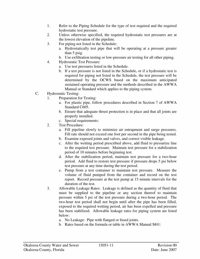
Okaloosa County Water and Sewer 15051-11 Revision 00 Okaloosa County, Florida Date: June 2007
1. Refer to the Piping Schedule for the type of test required and the required hydrostatic test pressure.
2. Unless otherwise specified, the required hydrostatic test pressures are at the lowest elevation of the pipeline.
3. For piping not listed in the Schedule: a. Hydrostatically test pipe that will be operating at a pressure greater
than 5 psig. b. Use exfiltration testing or low-pressure air testing for all other piping.
4. Hydrostatic Test Pressure: a. Use test pressures listed in the Schedule. b. If a test pressure is not listed in the Schedule, or if a hydrostatic test is
required for piping not listed in the Schedule, the test pressure will be determined by the OCWS based on the maximum anticipated sustained operating pressure and the methods described in the AWWA Manual or Standard which applies to the piping system.
C. Hydrostatic Testing: 1. Preparation for Testing:
a. For plastic pipe, follow procedures described in Section 7 of AWWA Standard C605.
b. Ensure that adequate thrust protection is in place and that all joints are properly installed.
c. Special requirements: 2. Test Procedure:
a. Fill pipeline slowly to minimize air entrapment and surge pressures. Fill rate should not exceed one foot per second in the pipe being tested.
b. Examine exposed joints and valves, and correct visible leakage. c. After the wetting period prescribed above, add fluid to pressurize line
to the required test pressure. Maintain test pressure for a stabilization period of 10 minutes before beginning test.
d. After the stabilization period, maintain test pressure for a two-hour period. Add fluid to restore test pressure if pressure drops 5 psi below test pressure at any time during the test period.
e. Pump from a test container to maintain test pressure. Measure the volume of fluid pumped from the container and record on the test report. Record pressure at the test pump at 15 minute intervals for the duration of the test.
3. Allowable Leakage Rates: Leakage is defined as the quantity of fluid that must be supplied to the pipeline or any section thereof to maintain pressure within 5 psi of the test pressure during a two-hour period. The two-hour test period shall not begin until after the pipe has been filled, exposed to the required wetting period, air has been expelled and pressure has been stabilized. Allowable leakage rates for piping system are listed below: a. No Leakage: Pipe with flanged or fused joints. b. Rates based on the formula or table in AWWA Manual M41:

Okaloosa County Water and Sewer 15051-12 Revision 00 Okaloosa County, Florida Date: June 2007
1) Metal pipe joined with rubber gaskets as sealing members. This includes the following joint types: • Push-on joints. • Mechanical joints. • Bolted sleeve type couplings. • Grooved and shouldered couplings.
c. Rates based on the formula or table in AWWA Standard 605: 1) Plastic pipe joined with O-ring gasket sealing members.
D. Exfiltration Testing: 1. Plug and bulkhead the section of pipe to be tested at both ends and admit
fluid until the pipe is full. 2. Provide a minimum head of 2 feet above the crown of the pipe at the
upstream end. 3. Add fluid from a test container or from a metered supply as required to
maintain the level within 3 inches of the minimum head throughout the test duration.
4. Test duration shall not be less than 2 hours. 5. Allowable Leakage Rates:
a. Leakage is defined as the quantity of fluid that must be supplied to the pipeline or any section thereof to maintain the head within 3 inches of the test elevation during the test duration after the pipe has been filled and exposed to the required wetting period plus the quantity required to refill to the original head.
b. Leakage shall not be greater than that allowed by the regulatory agency having jurisdiction.
E. Low Pressure Air Testing: 1. Test in accordance with requirements of the regulatory agency. 2. If there are no regulatory requirements use test procedures described in
ASTM Standards: a. ASTM F1417 – For thermoplastic pipe.
3.5 CLEANING AND DISINFECTION
A. Cleaning: 1. Thoroughly clean all piping and flush in a manner approved by OCWS,
prior to placing in service. 2. If piping which requires disinfection has not been kept clean during
storage or installation, CONTRACTOR shall swab each section individually before installation with a five percent hypochlorite solution, to ensure clean piping.
B. Disinfection: 1. Disinfect all potable and finished water piping. 2. A suggested procedure for accomplishing complete and satisfactory
disinfection is specified below. Other procedures will be considered for approval by OCWS. a. Thoroughly flush piping prior to disinfection with water.

Okaloosa County Water and Sewer 15051-13 Revision 00 Okaloosa County, Florida Date: June 2007
b. Conform to procedures described in AWWA C651. Continuous feed method of disinfecting shall be used unless alternative method is acceptable to OCWS.
3. Water for initial flushing, testing and chlorination will be furnished by the CONTRACTOR. CONTRACTOR shall provide all temporary piping, hose, valves, appurtenances and services required. Cost of water required for redisinfection will be paid by CONTRACTOR to OWNER at OWNER'S standard rates.
4. Chlorine will be supplied by CONTRACTOR. 5. Bacteriologic tests will be performed by OWNER. A certified test
laboratory report will be made available to CONTRACTOR, if requested. 6. Chlorine concentration in the water entering the piping shall be between
50 and 100 parts per million, such that a minimum residual concentration of 25 mg/l will be left after a 24-hour retention period. Care shall be taken to ensure disinfection of the piping in all its parts. The operation shall be repeated as necessary to provide complete disinfection.
7. After the required retention period, the heavily chlorinated water shall be flushed to drain, unless otherwise directed.
3.6 PIPING SCHEDULE
Service Size Material Interior Lining Exterior Coating Pressure
Class Joint Test Remarks
PW 4”-12” D.I. CL BC 350 B.S. HY
PW 4”-12” PVC -- -- C900 B.S. HY
FM 4”-12” D.I. EC CL BC 350 B.S. HY
FM 4”-12” HDPE -- -- As Required B.W. HY
SS 8”-12” D.I. EC BC 350 B.S. AIR
SS 8”-12” PVC -- -- ASTM 3034 B.S. AIR The following abbreviations are used in the piping schedule:
A. Service Abbreviations Potable Water PW Secondary Sludge SS Force Main FM
B. Material Abbreviations Polyvinyl Chloride PVC Ductile Iron DI High Density Polyethylene HDPE
C. Lining/Coating Abbreviations Cement Lined CL Bituminous Coated BC Epoxy Coated EC
D. Joint Abbreviations Belt and Spigot BS Flanged Flg
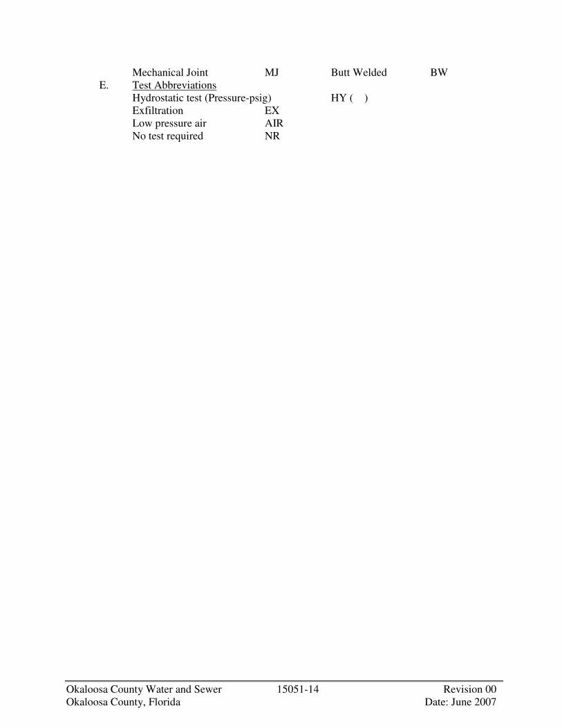
Okaloosa County Water and Sewer 15051-14 Revision 00 Okaloosa County, Florida Date: June 2007
Mechanical Joint MJ Butt Welded BW E. Test Abbreviations
Hydrostatic test (Pressure-psig) HY ( ) Exfiltration EX Low pressure air AIR No test required NR

Okaloosa County Water and Sewer 15052-1 Revision 00 Okaloosa County, Florida Date: June 2007
SECTION 15052
EXPOSED PIPING
PART 1 - GENERAL
1.1 DESCRIPTION
A. Scope: 1. CONTRACTOR shall provide all labor, materials, equipment and
incidentals as shown, specified and required to install and test all exposed piping, fittings, and specials. The Work includes, but is not limited to, the following: a. All types and sizes of exposed piping, except those specified under
other Sections or other contracts. b. Piping embedded in concrete within a structure or foundation will be
considered as exposed and included herein. c. Supports, restraints, thrust blocks and other anchors. d. Work on or affecting existing piping. e. Testing. f. Cleaning and disinfecting. g. Installation of all jointing and gasketing materials, specials, flexible
couplings, mechanical couplings, harnessed and flanged adapters, sleeves, tie rods, and all other Work required to complete the exposed piping installation.
h. Incorporation of valves, meters and special items shown or specified into the piping systems as required and as specified in the appropriate Division 15 Sections.
i. Unless otherwise specifically shown, specified, or included under other Sections, all exposed piping Work required, beginning at the outside face of structures or structure foundation and extending into the structure.
B. Coordination: 1. Review installation procedures under other Sections and other contracts
and coordinate with the Work that is related to this Section. 2. Section 15052 specifies the installation of all exposed piping materials
specified in Sections 15061 through 15070, and Sections 15121, and 15122. Coordinate with these Sections.
C. Related Sections: 1. Section 03300, Cast-In-Place Concrete. 2. Section 09900, Painting. 3. Division 15, Sections on Piping, Valves and Appurtenances.
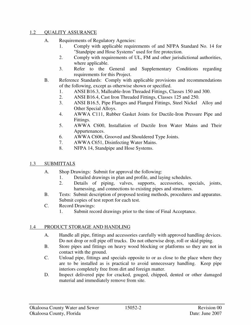
Okaloosa County Water and Sewer 15052-2 Revision 00 Okaloosa County, Florida Date: June 2007
1.2 QUALITY ASSURANCE
A. Requirements of Regulatory Agencies: 1. Comply with applicable requirements of and NFPA Standard No. 14 for
"Standpipe and Hose Systems" used for fire protection. 2. Comply with requirements of UL, FM and other jurisdictional authorities,
where applicable. 3. Refer to the General and Supplementary Conditions regarding
requirements for this Project. B. Reference Standards: Comply with applicable provisions and recommendations
of the following, except as otherwise shown or specified. 1. ANSI B16.3, Malleable-Iron Threaded Fittings, Classes 150 and 300. 2. ANSI B16.4, Cast Iron Threaded Fittings, Classes 125 and 250. 3. ANSI B16.5, Pipe Flanges and Flanged Fittings, Steel Nickel Alloy and
Other Special Alloys. 4. AWWA C111, Rubber Gasket Joints for Ductile-Iron Pressure Pipe and
Fittings. 5. AWWA C600, Installation of Ductile Iron Water Mains and Their
Appurtenances. 6. AWWA C606, Grooved and Shouldered Type Joints. 7. AWWA C651, Disinfecting Water Mains. 8. NFPA 14, Standpipe and Hose Systems.
1.3 SUBMITTALS
A. Shop Drawings: Submit for approval the following: 1. Detailed drawings in plan and profile, and laying schedules. 2. Details of piping, valves, supports, accessories, specials, joints,
harnessing, and connections to existing pipes and structures. B. Tests: Submit description of proposed testing methods, procedures and apparatus.
Submit copies of test report for each test. C. Record Drawings:
1. Submit record drawings prior to the time of Final Acceptance.
1.4 PRODUCT STORAGE AND HANDLING
A. Handle all pipe, fittings and accessories carefully with approved handling devices. Do not drop or roll pipe off trucks. Do not otherwise drop, roll or skid piping.
B. Store pipes and fittings on heavy wood blocking or platforms so they are not in contact with the ground.
C. Unload pipe, fittings and specials opposite to or as close to the place where they are to be installed as is practical to avoid unnecessary handling. Keep pipe interiors completely free from dirt and foreign matter.
D. Inspect delivered pipe for cracked, gouged, chipped, dented or other damaged material and immediately remove from site.

Okaloosa County Water and Sewer 15052-3 Revision 00 Okaloosa County, Florida Date: June 2007
PART 2 - PRODUCTS
2.1 MATERIALS
A. Required pipe materials are listed in the Piping Schedule. Refer to applicable Sections for material specifications.
B. General: 1. Marking Piping:
a. Clearly mark each piece of pipe or fitting with a designation conforming to that shown on the Shop Drawings.
b. Cast or paint material, type and pressure designation on each piece of pipe or fitting 4 inches in diameter and larger.
c. Pipe and fittings smaller than 4 inches in diameter shall be clearly marked by manufacturer as to material, type and rating.
C. Pipe Identification Markers and Arrows: Refer to Section 09900, Painting.
PART 3 - EXECUTION
3.1 INSTALLATION
A. General: 1. Install piping as shown, specified and as recommended by the
manufacturer. 2. If there is a conflict between manufacturer's recommendations and the
Drawings or Specifications request instructions from OCWS before proceeding.
B. Piping Installation: 1. Install straight runs true to line and elevation. 2. Install vertical pipe truly plumb in all directions. 3. Protect and keep clean water pipe interiors, fittings and valves. 4. Provide temporary caps or plugs over all pipe openings at the end of each
days work, and when otherwise required or directed by OCWS. 5. Cutting: Cut pipe from measurements taken at site, not from Drawings. 6. Install dielectric unions wherever dissimilar metals are connected except
for bronze or brass valves in ferrous piping. 7. Provide a union downstream of each valve with screwed connections. 8. Provide screwed or flanged unions at each piece of equipment, where
shown, and where necessary to install or dismantle piping. C. Joints:
1. General: a. Make joints in accordance with the pipe manufacturer's
recommendations and the requirements below. b. Cut piping accurately and squarely and install without forcing or
springing.

Okaloosa County Water and Sewer 15052-4 Revision 00 Okaloosa County, Florida Date: June 2007
c. Ream out all pipes to full inside diameter after cutting. Remove all sharp edges on end cuts.
d. Remove all cuttings and foreign matter from the inside of pipe before installation. Thoroughly clean all pipe, fittings, valves, specials, and accessories before installing.
2. Mechanical Joint Pipe: a. Wipe clean the socket, plain end, and adjacent areas immediately
before making joint. Make certain that cut ends are tapered and sharp edges are filed off smooth.
b. Lubricate the plain end and gasket with soapy water or an approved pipe lubricant, in accordance with AWWA C111, just prior to slipping the gasket onto the plain end of the joint assembly.
c. Place the gland on the plain end with the lip extension toward the plain end, followed by the gasket with the narrow edge of the gasket toward the plain end.
d. Insert the pipe into the socket and press the gasket firmly and evenly into the gasket recess. Keep the joint straight during assembly.
e. Push gland toward socket and center it around pipe with the gland lip against the gasket.
f. Insert bolts and hand tighten nuts. g. Make deflection after joint assembly, if required, but prior to
tightening bolts. Alternately tighten bolts 180 degrees apart to seat the gasket evenly. The bolt torque shall be as follows:
Pipe Size Bolt Size Range of Torque (inches) (inches) (ft-lbs)
3 5/8 45-60
4-24 3/4 75-90 30-36 1 100-120 42-48 1-1/4 120-150
3. Flanged Joints:
a. Assemble flanged joints using 1/8-inch ring-type gaskets for raised face flanges. Use full face gaskets for flat face flanges unless otherwise approved by OCWS. Gaskets shall be suitable for the service intended in accordance with the manufacturer's ratings and instructions. Gaskets shall be properly centered.
b. Bolts shall be tightened in a sequence, which will insure equal distribution of bolt loads.
c. The length of bolts shall be uniform, and they shall not project beyond the nut more than 1/4-inch or fall short of the nut when fully taken up. The ends of bolts shall be machine cut so as to be neatly rounded. No washers shall be used.
d. Bolt threads and gasket faces for flanged joints shall be lubricated prior to assembly.

Okaloosa County Water and Sewer 15052-5 Revision 00 Okaloosa County, Florida Date: June 2007
e. Alternately tighten bolts 180 degrees apart to compress the gasket evenly.
D. Installing Valves and Accessories: 1. Provide supports for large valves, flow meters and other heavy items as
shown or required. 2. Install floor stands as shown and as recommended by the manufacturer. 3. Provide lateral restraints for extension bonnets and extension stems as
shown and as recommended by the manufacturer. 4. Provide steel sleeves where operating stems pass through floor. Extend
sleeves 2 inches above floor. 5. Position valve operators as shown. When the position is not shown, install
the valve so that it can be conveniently operated and as approved by OCWS. Avoid placing operators at angles to the floors or walls.
6. Position flow measuring devices in pipe lines so that they have the amount of straight upstream and down stream runs recommended by the manufacturer, unless specific location dimensions are shown. Position swing check valves so that they do not conflict with the discs of butterfly valves.
E. Unions: 1. Install dielectric unions wherever dissimilar metals are connected except
for bronze or brass valves in ferrous piping. 2. Provide a union downstream of each valve with screwed connections. 3. Provide screwed or flanged unions at each piece of equipment, where
shown, and where necessary to install or dismantle piping. F. Eccentric Reducers: Use eccentric reducers where shown and where air or water
pockets would otherwise occur in mains because of a reduction in pipe size. G. Transitions from One Type of Pipe to Another:
1. Provide all necessary adapters, specials and connection pieces required when connecting different types and sizes of pipe or connecting pipe made by different manufacturers.
H. Taking Existing Pipelines Out of Service: 1. Do not take pipelines out of service unless specifically approved by
OCWS. 2. Notify OCWS at least 48 hours prior to taking pipeline out of service.
I. Work on Existing Pipelines: 1. Cut or tap pipes as shown or required with machines specifically designed
for this work. 2. Install temporary plugs to keep out all dirt, water and debris. 3. Provide all necessary adapters, fittings, pipe and appurtenances required.
3.2 THRUST RESTRAINT
A. Provide thrust restraint on all pressure piping systems and where otherwise shown or specified.

Okaloosa County Water and Sewer 15052-6 Revision 00 Okaloosa County, Florida Date: June 2007
B. Thrust restraint may be accomplished by means of restrained pipe joints. Thrust restraints shall be designed for the axial thrust exerted by the test pressure specified in the "Exposed Piping Schedule".
C. Restrained Pipe Joints: 1. Pipe joints shall be restrained by means suitable for the type of pipe being
installed. a. Restrain concrete pipe joints utilizing bell bolt, clamp type, or snap
ring type restrained joints. b. Restrain ductile iron mechanical joint pipe utilizing tie rods and
clamps or proprietary restrained joint system such as American Lok-Fast, Fast-Tite, U.S. Trim-Tite or equal.
c. Restrain ductile iron pipe connected by flexible couplings or flanged coupling adapters by harnessing across the coupling or adapter using tie rods or extended bolts connecting between flanges.
d. Steel pipe shall have butt-welded joints, flanged joints, or flexible or mechanical coupling connectors. Provide tie rods connected to ears welded to the steel pipe for restraint at all flexible coupling connectors.
3.3 PAINTING
A. Field painting is under Section 09900.
3.4 TESTING OF PIPING
A. General: 1. Test all piping as specified below unless otherwise authorized by OCWS. 2. Notify OCWS 48 hours in advance of testing. 3. Provide all testing apparatus including pumps, hoses, gages, and fittings. 4. Pipelines shall hold the specified test pressure for two hours. 5. Repair and retest pipelines which fail to hold specified test pressures or
which exceed the allowable leakage rate. 6. Test pressures required are at the lowest elevation of the pipeline section
being tested, unless otherwise specified. 7. Conduct all tests in the presence of OCWS. Repeat tests in the presence
of local authorities having jurisdiction, if required. B. Schedule of Pipeline Tests:
1. Test piping at the test pressure listed in the Exposed Piping Schedule. 2. For piping not included in the Schedule, OCWS will notify
CONTRACTOR in writing of the test pressure to be utilized. C. Pressure Test Procedure:
1. Insure that all supports and restraint protection are securely in place. 2. Fill section to be tested slowly with water and expel all air. Install cocks,
if necessary, to ensure removal of air. 3. Test only one section of pipe at a time. 4. Apply specified test pressure required for two hours and observe pressure
gage. Check carefully for leaks while test pressure is being maintained.

Okaloosa County Water and Sewer 15052-7 Revision 00 Okaloosa County, Florida Date: June 2007
3.5 CLEANING AND DISINFECTION
A. Cleaning: 1. Thoroughly clean all piping and flush prior to placing in service in a
manner approved by OCWS. 2. Piping 24 inches in diameter and larger shall be inspected from inside and
all debris, dirt and foreign matter removed. 3. If piping which requires disinfection has not been kept clean during
storage or installation, CONTRACTOR shall swab each section individually with a five percent hypochlorite solution, to ensure clean piping.
B. Disinfection: 1. Disinfect all potable and finished water piping. 2. A suggested procedure for accomplishing disinfection is specified below.
Other procedures will be considered for approval by OCWS. a. Thoroughly flush piping prior to disinfection with water. b. Conform to procedures described in AWWA C651. Continuous feed
method of disinfecting shall be used unless alternative methods is acceptable to OCWS.
3. Water for initial flushing, testing and chlorination will be furnished by CONTRACTOR. CONTRACTOR shall provide all temporary piping, hose, valves, appurtenances and services required. Cost of water required for redisinfection will be paid by CONTRACTOR to OWNER at OWNER'S standard rates.
4. Chlorine will be supplied by CONTRACTOR. 5. Bacteriologic tests will be performed by OWNER. A certified laboratory
report will be available to CONTRACTOR, if requested. 6. Chlorine concentration in the water entering the piping shall be between
50 and 100 parts per million, such that a minimum residual concentration of 25 mg/l will be left after a 24-hour retention period. Care shall be taken to insure disinfection of the piping in all its parts. The operation shall be repeated as necessary to provide complete disinfection.
7. After the required retention period, the heavily chlorinated water shall be flushed to drain, unless otherwise directed.
3.6 PIPING SCHEDULE
Service Size Material Interior Lining
Exterior Coating
Pressure Class Joint Test Remarks
PW 4”-12” D.I. CL BC 350 Flg MJ HY
FM 4”-12” D.I. EC CL BC 350 Flg
MJ HY
�
Okaloosa County Water and Sewer 15052-8 Revision 00 Okaloosa County, Florida Date: June 2007
The following abbreviations are used in the piping schedule. A. Service Abbreviations
Potable Water PW Force Main FM
B. Material Abbreviations Ductile Iron DI
C. Lining Abbreviations Cement Lined CL Painted P Epoxy Coated EC
D. Joint Abbreviations Flanged Flg Mechanical Joint MJ

Okaloosa County Water and Sewer 15100-1 Revision 00 Okaloosa County, Florida Date: June 2007
SECTION 15100
VALVES, 4-INCH AND LARGER
PART 1 - GENERAL
1.1 DESCRIPTION
A. Scope: 1. CONTRACTOR shall provide all labor, materials, equipment and
incidentals as shown, specified and required to furnish and install 4-inch and larger valves and appurtenances, complete and operational.
B. Related Sections: 1. Section 09900, Painting. 2. Section 15051, Buried Piping Installation. 3. Section 15052, Exposed Piping Installation.
1.2 REFERENCES
A. Comply with the applicable provisions and recommendations of the following standards, except as otherwise shown or specified.
B. ANSI Standards: 1. B16.1, Cast-Iron Pipe Flanges and Flanged Fittings. 2. B16.34, Valves-Flanged, Threaded, and Welding End.
C. API Standards: 1. 594, Wafer Check Valves. 2. 598, Valve Inspection and Test. 3. 609, Butterfly Valves, Lug-Type and Wafer-Type.
D. ASTM Standards: 1. A126, Gray Iron Castings for Valves, Flanges and Pipe Fittings. 2. A193, Alloy Steel and Stainless Steel Bolting Materials for High
Temperature Service. 3. A194, Specification for Carbon and Alloy Steel Nuts for Bolts for High
Pressure and High Temperature Service. 4. A307, Carbon Steel Externally Threaded Standard Fasteners. 5. A380, Practice for Cleaning and Descaling Stainless Steel Parts,
Equipment and Systems. 6. A536, Ductile Iron Castings. 7. A743, Castings, Iron-Chromium, Iron-Chromium-Nickel, Corrosion
Resistant, for General Application. 8. B21, Naval Brass, Rod, Bar, and Shapes. 9. B61, Steam or Valve Bronze Castings. 10. B62, Composition Bronze or Ounce Metal Castings. 11. B98, Copper-Silicon Alloy Rod, Bar, and Shapes. 12. B124, Copper and Copper Alloy Forging Rod, Bar and Shapes.
Okaloosa County Water and Sewer 15100-2 Revision 00 Okaloosa County, Florida Date: June 2007
13. B138, Manganese Bronze Rod, Bar and Shapes. 14. D429, Test Methods for Rubber Property - Adhesion to Rigid Substrates. 15. B584, Copper Alloy Sand Castings for General Applications.
E. AWWA Standards: 1. C502, Dry-Barrel Fire Hydrants. 2. C504, Rubber-Seated Butterfly Valves. 3. C507, Ball Valves, 6 Inch Through 48 Inch. 4. C508, Swing-Check Valves for Waterworks Service, 2 Inch Through 24
Inch. 5. C509, Resilient-Seated Gate Valves for Water Supply Service. 6. C550, Protective Epoxy Interior Coatings for Valves and Hydrants.
1.3 QUALITY ASSURANCE
A. Qualifications: 1. Manufacturer:
a. Minimum of five years of experience producing substantially similar equipment and able to show evidence of at least five installations in satisfactory operation for at least five years in the continental United States.
b. Equipment shall be manufactured in the United States. B. Component Supply and Compatibility:
1. Obtain all equipment included in this Section, regardless of the component manufacturer, from the valve manufacturer to ensure compatibility and proper operation.
1.4 SUBMITTALS
A. Shop Drawings: 1. Product data sheets. 2. Complete catalog information, including dimensions, weight,
specifications, and identification of materials of construction of all parts. 3. Cv values and headloss curves. 4. Certificates of compliance with AWWA Standards where applicable. 5. Corrosion resistance information to confirm suitability of the valve
materials for the application. Information on chemical resistance of elastomers shall be furnished from the elastomer manufacturers.
B. Certified copies of shop test results and inspection data. C. Operation and Maintenance Data: Submit complete manuals including:
1. Copies of all approved Shop Drawings, test reports, maintenance data and schedules, description of operation, and spare parts information.

Okaloosa County Water and Sewer 15100-3 Revision 00 Okaloosa County, Florida Date: June 2007
PART 2 - PRODUCTS
2.1 GENERAL PROVISIONS
A. Manually operated valves, with or without extension stems, shall require not more than a 40-pound pull on the manual operator to open or close a valve against the specified criteria. The gear actuator and the valve components shall be able to withstand a minimum pull of 200 pounds on the manual operator and an input torque of 300 foot pounds to an actuator nut. Manual operators include handwheel, and a T-handle wrench.
B. Provide all valves to turn clockwise to close, unless otherwise specified. C. Provide all valves with permanent markings for direction to open. D. Provide exposed valves with flanged ends conforming to ANSI B16.1. The
pressure class of the flanges shall be equal to or greater than the specified pressure rating of the valves.
E. Provide buried valves with mechanical or push-on joints, restrained or unrestrained, as required by the piping with which they are installed.
F. All materials of construction of the valves shall be suitable for the application as shown on the Drawings.
G. Protect wetted parts from galvanic corrosion due to contact of two different metals.
H. Provide all valves with manufacturer’s name and rated pressure cast in raised letters on the valve body.
I. Provide valves with brass or Type 316 stainless steel nameplates attached with Type 316 stainless steel screws. Nameplates shall have engraved letters and shall include the following information as a minimum: 1. Valve size. 2. Pressure and temperature ratings. 3. Application (other than water and wastewater). 4. Date of manufacture. 5. Manufacturer’s name.
J. Clean and descale fabricated stainless steel items in accordance with ASTM A380, and as follows: 1. Passivate all stainless steel welded fabricated items after manufacture by
immersion in a pickling solution of 6 percent nitric acid and 3 percent hydrofluoric acid. Temperature and detention time shall be sufficient for removal of oxidation and ferrous contamination without etching the surface. Perform a complete neutralizing operation by immersion in a trisodium phosphate rinse followed by a clean water wash.
2. Scrub welds with the same pickling solution or pickling paste and clean with stainless steel wire brushes or by grinding with non-metallic abrasive tools to remove weld discoloration, and then neutralize and wash clean.
K. For stainless steel bolting, except where Nitronic-60 nuts are required, use anti-seize compound, graphite free, to prevent galling. Strength of the joint shall not be affected by the use of anti-seize compound.

Okaloosa County Water and Sewer 15100-4 Revision 00 Okaloosa County, Florida Date: June 2007
2.2 APPURTENANCES FOR EXPOSED METALLIC VALVES
A. Handwheels: 1. Conform to the applicable AWWA Standards. 2. Material of Construction: Ductile iron or cast aluminum. 3. Arrow indicating direction of opening and word “OPEN” shall be cast on
the trim of the handwheel. 4. Maximum Handwheel Diameter: 30 inches.
2.3 APPURTENANCES FOR BURIED METALLIC VALVES
A. Wrench Nuts: 1. Provide wrench nuts on all buried valves of nominal 2-inch size
conforming to AWWA C500. 2. Arrow indicating direction of opening the valve shall be cast on the nut
along with the word “OPEN”. 3. Material: Ductile iron. 4. The nut shall be secured to the stem by mechanical means.
B. Extension Stems for Non-Rising Stem Gate Valves and Quarter Turn Buried Valves: 1. Provide extension stems to bring the operating nut to 6 inches below the
valve box cover. 2. Minimum Size and Material: Same as valve stem. 3. Maximum Unsupported Length: 3 feet. 4. Provide top nut and bottom coupling of ductile iron with pins and set
screws of Type 316 stainless steel. C. Valve Boxes:
1. Valve boxes shall be as indicated and as required. 2. Type: Heavy duty, suitable for highway loading, 2-piece telescopic, and
adjustable. Lower section shall enclose operating nut and stuffing box and rest on bonnet.
3. Material: Cast or ductile iron. 4. Coating: Two coats of asphalt varnish conforming to Federal
Specification TT-C-494. 5. Marking: As required for service.
2.4 ANCHOR AND MISCELLANEOUS MOUNTING BOLTS
A. All bolts, nuts and washers for connection of the valve appurtenances to concrete structure or other structural members shall be obtained from the valve manufacturer, and shall be of ample size and strength for the purpose intended. Anchor bolts shall be hooked or adhesive type.
B. Provide anchor bolts for stem guides of required strength to prevent twisting or sagging of the guides under load.
C. Provide bolts and washers of Type 316 stainless steel and nuts of Nitronic 60. The bolts shall have rolled threads and both bolts and nuts shall be electropolished to remove burrs.

Okaloosa County Water and Sewer 15100-5 Revision 00 Okaloosa County, Florida Date: June 2007
D. Minimum Size of Anchor Bolts: 5/8 inch.
2.5 PAINTING OF EXPOSED VALVES, HYDRANTS AND APPURTENANCES
A. Exterior steel, cast-iron, and ductile iron surfaces except machined surfaces of all exposed valves and appurtenances shall be finish painted in the shop. The surface preparation, priming, finish painting, and field touch-up painting shall conform to Section 09900.
2.6 PAINTING OF BURIED VALVES
A. Exterior steel, cast-iron, and ductile iron surfaces except machined or bearing surfaces of all buried valves shall be shop-painted with two coats of asphalt varnish conforming to Federal Specification TT-C 494.
PART 3 - EXECUTION
3.1 INSTALLATION
A. Install all valves and appurtenances in accordance with the manufacturer's instructions.
B. Conform to appendices of AWWA Standards, where applicable. C. Install all valves so that operating handwheels or levers can be conveniently
turned from operating floor without interfering with access to other valves and equipment, and as approved by the ENGINEER. Orient chain operators out of the way of the walking areas. Mount valves so that indicator arrows are visible from floor level.
D. For motor-operated valves located lower than five feet above the operating floor, orient the motor actuator to permit easy access to the push buttons and the handwheel.
E. Install all valves plumb and level. Install all valves to be free from distortion and strain caused by misaligned piping, equipment or other causes.
F. For buried valve installations, set valve boxes plumb and centered, with soil carefully tamped to a lateral distance of 4 feet on all sides of the box, or to the undisturbed trench face if less than 4 feet. Provide a flexible coupling next to a buried valve for ease of valve removal.
G. Install plug valves in horizontal liquid lines with the stem horizontal and the plugs on top when the valves are open and the plugs on upstream end when the valves are closed. Install valves in vertical liquid lines with the plug at the top when closed.
3.2 FIELD TESTS AND ADJUSTMENTS
A. Adjust all parts and components as required to provide correct operation of the valves.

Okaloosa County Water and Sewer 15100-6 Revision 00 Okaloosa County, Florida Date: June 2007
B. Conduct a functional field test on each valve in the presence of the ENGINEER to demonstrate that each valve operates correctly.
C. Verify satisfactory operation and controls of motor operated valves. D. Demonstrate satisfactory opening and closing of valves at the specified criteria
requiring not more than 40 pounds effort on the manual actuators. E. Test 10 percent valves of each type by applying 200 pounds effort on the manual
operators. There shall be no damage to the gear actuator or the valve.

OKALOOSA COUNTY WATER AND SEWER
DIVISION 16
Okaloosa County Water and Sewer Revision 00 Okaloosa County, Florida Date: June 2007
DIVISION 16 ELECTRICAL
SECTION 16600 INTEGRATED SPECIFICATION SECTION 16610 TRANSIENT VOLTAGE SURGE SUPPRESSION (TVSS)
EQUIPMENT


Okaloosa County Water and Sewer 16600-1 Revision 00 Okaloosa County, Florida Date: June 2007
SECTION 16600
INTEGRATED SPECIFICATION
PART 1 – GENERAL REQUIREMENTS
1.1 GENERAL INTEGRATOR SPECIFICATIONS
A. The control system shall be a complete integrated system with the MCC pedestal panel with starters, KW meter section and L2000 controller, instrumentation, telemetry and SCADA as a complete package. The integrator shall assume responsibility for the performance of the complete integrated control system. The integrator shall perform a factory test as a complete integrated package prior to shipment. The factory test of the completed system shall be witnessed by the Engineer and/or the End User prior to shipment to the job site. The equipment shall not be shipped to the job site unless written notice to ship is received from the Engineer. The integrated control system shall be supplied by TESCO Controls Incorporated or pre-approved equal.
1.2 ENCLOSURE
A. Furnish and install all equipment as shown on drawings in a low profile 60-inch high (as specified on drawing), U.L. listed weatherproof NEMA 3R switchboard and instrument pedestal. Enclosure shall consist of a TESCO Class 24-000 section, with dead front interior and hinged gasketed exterior doors. Outer enclosure shall be constructed of 14 gauge 304 stainless steel with no exposed bolts, screws or lifting eyes. Doors shall be equipped with 316 stainless steel handles with 3-point roller bearing latches and hasps for owner padlocks. Concrete base with anchor bolts to meet applicable seismic requirements shall be provided. Provide an integrated pedestal panel with a fluorescent light and door switch per door, GFCI receptacle, ATS - if required, strip heater, thermostat and TVSS’s - as required per specification. Integrated into the pedestal panel will also be the KW Meter with approval of Golf Power and meet all WUESSC requirements, DM Series Power Monitor per pump, PFR power fail relay and integrated L2000 controller, which will communicate back to SCADA all the above alarm points. Seal all openings to prevent entrance of insects and rodents. Finish shall be polyester dry powder, electrostatically applied and baked on at 380 deg. F. The painting process shall include five stages of metal preparation using dip tanks as follows: 1) Alkaline cleaner, 2) Clear water rinse, 3) Iron phosphate application, 4) Clear water rinse, and 5) Inhibitive rinse to seal phosphated surfaces. All bussing and wire shall be copper. All wire shall be stranded with locking spade pressure connectors and labeled with clip-on permanent plastic wire markers. All circuit breakers and dead front mounted devices (lights and switches) shall be equipped with engraved phenolic nameplates.

Okaloosa County Water and Sewer 16600-2 Revision 00 Okaloosa County, Florida Date: June 2007
B. The enclosure shall be compartmentalized such that the programmable pump controller and power sections are isolated from each other. The compartments containing the programmable pump controller and power sections shall be separated by barriers behind the inner dead front door. Doors shall be hinged on the same side and shall open to greater than 90 degrees. All dead front latches are 1/4 turn adjustable with 1/8" thick latching dog and knurled knob.
C. Thermostatically controlled heating and cooling systems shall be provided, if required, and as approved by the Engineer to maintain suitable climate conditions within the control panel as required to provide proper operation of the panel and to comply with the Drawings and Specifications.
1.3 CIRCUIT BREAKERS
A. All 480 volt circuit breakers shall have interrupting capacities at 14,000 amperes. All 120 volt breakers shall be rated 10,000 amperes interrupting capacity. Circuit breakers shall be of the indicating type, providing ON, OFF and TRIPPED positions of the operating handle. Circuit breakers shall be quick-make, quick-break, with a thermal-magnetic action, except when protecting motor feeders where motor circuit protector (MCP) breakers may be used. Circuit breakers shall be the bolted on type. The use of tandem or dual circuit breakers in a normal single- pole space to provide the number of poles or spaces specified is not acceptable. All multiple-pole circuit breakers shall be designed so that an overload on one pole automatically causes all poles to open. Circuit breakers shall meet the requirements of UL and NEMA AB l. Breakers shall be Westinghouse EHD , MCP,or equal.
1.4 GROUNDING SYSTEM
A. The switchboard ground bus and incoming neutral service conductor shall be connected to a "rod" type "ground". The ground rod shall be 3/4" x 10' copper clad with connection made by exothermic weld and driven in earth at base of pedestal. The ground rod shall extend up into pedestal for visible connection with an approved "exothermic weld". Grounding and bonding wires shall be installed in all PVC conduit runs and connected to ground bus and all equipment. 1. Thermite welding materials shall be of size and type recommended by the
manufacturer for the intended use. Materials shall be Burndy, Cadweld, manufactured by Erico Products, Inc., or equal.
2. Grounding conductor - All grounding conductor shall be sized as shown on plans or in accordance with NEC Table 250-95, whichever is larger.
3. Ground bus - A ground bus shall be provided in the service equipment. It shall be connected to the grounding electrode system by exothermic welded stranded copper grounding conductors. Screw type lugs shall be provided for connection of equipment grounding conductors
4. Okaloosa County Minimum Requirements – for Lightning Protection, Grounding and Bonding

Okaloosa County Water and Sewer 16600-3 Revision 00 Okaloosa County, Florida Date: June 2007
1.5 LIGHTNING PROTECTION
A. Each site shall have its electrical power protected by transient voltage surge suppression (TVSS) at the “service entrance,” power section, at the generator transfer switch - if equipped, the power to the SCADA equipment and at each electrical panel serving the site. The manufacturer of these surge protective devices (SPD) shall ensure that their products as submitted meet or exceed the minimum standards as set forth in SECTION 16610 – attached.
1.6 GROUNDING AND BONDING
A. Each site shall have its electrical service entrance properly grounded and bonded as per National Electrical Code (NEC) with sufficient ground rods driven to a SUFFICIENT depth as to ensure a measured ground resistance of 25 Ohms, or less. Ground rods shall be 5/8” diameter, copper-clad with threaded ends at a minimum. The wire used for grounding shall be un-insulated #6 solid copper wire at a minimum as well. Exothermic welding shall be used to permanently bond the ground wire to the ground rods. The contractor shall be required to provide documentation of the measured ground resistance testing that proves compliance with this requirement. Each electrical ground for equipment situated at the site shall be properly bonded to this single point ground. Multiple independent ground rods are not allowed. Every effort to ensure that there is no difference in ground potential between equipment at the site shall be made.
B. Okaloosa County reserves the right to bring in an outside contractor to check and verify compliance with this standard.
1.7 LUMINARIES
A. The luminaries shall be the size and type normally supplied with the specified cubicles. As a minimum, the luminaries shall be a 15 to 30 watt rapid start fluorescent strip type fixture with warm white lamps. A lens or guard shall be furnished and installed over each lamp. The fixture ballasts shall be capable of providing reliable starts with ambient temperatures down to 30 degrees. Ballast noise shall not exceed 50 dBA. "Noisy" ballasts shall be replaced by and at the Contractor's expense.
1.8 MOTOR CONTROLS, GENERAL
A. Provide each motor with a suitable controller and devices that will perform the functions as specified for the respective motors. Controllers shall conform to the applicable requirements of NEMA ICS, ANSI C19.1, the NEC, and UL. Anticipated horsepower ratings and enclosures are shown on the plans. This information is for guidance only and does not limit the equipment size. When motors furnished differ from the expected ratings indicated, make the necessary adjustments to wiring, conduit, disconnect devices, motor starters, branch circuit protection, and other affected material or equipment to accommodate the motors actually installed, at no additional cost to the Owner.

Okaloosa County Water and Sewer 16600-4 Revision 00 Okaloosa County, Florida Date: June 2007
B. Each motor control system shall be equipped with a hand- off-auto control switch, indicating lights, elapsed time meter, motor starter, control transformer with primary fuses and secondary control power fuse. 1. Control switches and indicating lights shall be U.L. listed oil-tight devices
rated heavy duty. Provide Idec, Westinghouse, or equal. 2. Elapsed time meters shall be non-resettable with 0.0 to 99,999.9 readout.
Provide Engler, Yokogawa, or equal. 3. Motor starters shall be NEMA rated with an electrically held contractor
and a single reset, 3 phase, overload relay with a normally closed holding contact and a normally open isolated contact for overload alarm. Each overload shall be ambient compensated and shall trip on 600% of full load current in less than 6 seconds. Each motor starter Size 3 and larger shall be furnished with a minimum of 4 auxiliary contacts and provisions for adding 2 more. Auxiliary contacts shall be convertible, in the field, from normally open to normally closed. Each overload relay shall have a test trip push-button built-in and a adjustable calibrated trip with indicating dial. There shall be an unbreakable steel operator, with insulated plastic foot (for safety) through the front door for manual reset. Provide Westinghouse A201, Allen Bradley 100, or equal.
4. Control power transformers shall be sized as shown on the plans, minimum size shall be 100VA where not designated. Provide Micron, G.E., Hevi-Duty, or equal.
1.9 NAMEPLATES
A. Nameplates shall be black phenolic with white lettering. Nameplates shall be screw mounted. Glue type will not be acceptable.
1.10 PANELBOARD
A. Panelboard shall be circuit breaker type custom constructed to utilize minimum enclosure space with breakers as shown. Circuit breakers shall be bolted on type. The panelboard shall be furnished with phenolic nameplates. The panelboard transformer shall be dry type construction sized as shown on the plans with primary breaker protection. The panelboard transformer shall be a Jefferson 211, Westinghouse, or equal.
1.11 PANEL LIGHTS
A. Furnish and install push-to-test lights to indicate status and alarm conditions locally as shown on drawings. Engraved phenolic nameplates shall specify each light's function. Lights shall be wired as shown on drawings.

Okaloosa County Water and Sewer 16600-5 Revision 00 Okaloosa County, Florida Date: June 2007
1.12 PUSH BUTTONS AND SELECTOR SWITCHES
A. Push-buttons, and selector switches, for non hazardous indoor dry locations shall be of the oil-tight type, Westinghouse Type OT, Idec ASN, General Electric Type CR 240, Square D Class 9001, or equal, and shall be mounted in equipment covers or oil-tight NEMA 1 enclosures, as indicated. These devices shall have individual, extra large nameplates indicating their specific function.
1.13 RECEPTACLES, DUPLEX
A. Receptacles shall be of specification grade and of NEMA configuration and rated 2 pole, 3 wire grounding, 20 amperes, 125 volts, such as Pass & Seymour 5252, Bryant 5252, or equal. Contact arrangement shall be such that contact is made on two sides of each inserted blade. Bases shall be of ivory phenolic composition. Wire terminals shall be suitable for 10 AWG wire and shall be screw type. Receptacles shall be UL listed. The receptacles shall have corrosion resistant conducting parts of nickel-plated brass and other metal parts of stainless steel. All external and dead front receptacles shall be installed on ground fault interrupter circuits "GFCI".
1.14 RELAYS, CONTROL
A. Control relays shall be Potter and Brumfield KU, Square D Type KU, Idec Type RH or equal. Two form-C contacts (minimum) shall be provided on each relay. Provide relay energized neon lamp (inside relay case).
1.15 POWER MONITORS AND POWER FAIL RELAYS
A. Power monitors shall communicate to the PLC controller with Modbus communications. Each unit shall have up to 10 channels of analog outputs, shall be able to show power quality, shall have a bright LED display, shall be able to show bidirectional with min/max on all electrical parameters and shall have true RMS measurements of Voltage, Current & Power as a minimum. Provide Electro Industries/GaugeTech model DMMS300+.
B. The power fail relay shall continuously monitor the three phases for power loss, low voltage, phase loss, phase reversal and have automatic reset. The power fail monitor shall have a drop-out voltage adjustment and a failure indicating LED. Provide Diversified model SLA, or equal.
1.16 RELAYS, PROBE
A. Probe relays shall be provided for functions as shown on plans, i.e. moisture probes, motor over-temperature, etc. The unit shall be specifically designed for monitoring conductivity type probes and switching type sensors in hazardous areas. The unit shall utilize low current (120 micro amps maximum) and low voltage (12 volts d-c maximum) limiting the power entering the hazardous area

Okaloosa County Water and Sewer 16600-6 Revision 00 Okaloosa County, Florida Date: June 2007
to less than 1.5 milli-watts. Unit sensitivity shall allow pick-up on circuit closures of 100 K ohms or less. The probe relay shall be a TESCO 72-144, or equal.
1.17 RELAYS, TIME DELAY
A. Time delay relays shall be solid state relays with a timer adjustable over the range 1 to 60 seconds unless other ranges are indicated or required. Provide LED relay energized indicator lamp. Time delay relays shall be IDEC RTE, Agastat STA, or equal.
1.18 SERVICE ENTRANCE
A. The electric service meter compartment shall be arranged approximately as shown to meet the electric utility company Gulf Power and WUESSC requirements. Provide neutral bar for grounding and a L&G Meter Socket with disconnect handle for bypass mechanism. Provide guard over power company watt hour meter with hinged access cover that has a hasp for utility company padlock. Provide wire and lugs for service entrance as required by utility company. The pull section and utility compartments shall be accessible only by the utility company. A lightning arrestor shall be provide to protect the panel equipment from lightning and utility power surges.
B. Provide a meter base, test perch with test by-pass and other materials, as required by the electric utility which will provide service to the facility, for installation of metering equipment and attachment of service conductors.
1.19 TERMINAL AND DISTRIBUTION BLOCKS
A. Distribution blocks shall be furnished and installed as required for "fan-out" of control power and other 120V sources within the enclosure. The blocks shall be rated 300V at a minimum of 20 amperes and sized for the conductors served. Distribution blocks shall be similar to Square D, Connectron NFT, or equal.
1.20 TVSS SPECIFICATIONS
A. The TVSS shall be from the Surge Suppression Incorporated Company line of products. TVSS shall have the capabilities of protecting the 120V PLC Equipment, 3Phase incoming Power & 3 Phase ATS (If Required).
1.21 PROGRAMABLE CONTROLLER SPECFICATION
A. The Programmable Controller shall have all the characteristics and features listed herein. All these features shall be readily available as an integral part of the Programmable Controller and shall be standard catalog items for the product. The use of any third party hardware or software add-on products to meet this specification is not acceptable. The Programmable Controller shall be an L2000 controller from Tesco Controls, Inc - no exceptions.

Okaloosa County Water and Sewer 16600-7 Revision 00 Okaloosa County, Florida Date: June 2007
B. Manufacturer 1. The Programmable Controller shall be procured from a manufacturer that
has at least 10 years experience manufacturing its own Programmable Controllers designed specifically for the water and waste water industry. The Programmable Controller itself and support for the controller shall be available directly from the manufacturer. Programming services shall be available direct from the manufacturer as a normal practice. The manufacturer shall also produce a Supervisory Control and Data Acquisition (SCADA) system that integrates directly with the Programmable Controller, supporting the controller's native communications protocol, to take full advantage of its capabilities.
C. Warranty 1. The Programmable Controller manufacturer shall provide a 5-year
warranty with the unit. A 10-year warranty shall be available at additional cost. These warranties shall be available in writing directly from the manufacturer before bid acceptance. A warranty or service contract from a source other than the Programmable Controller manufacturer is not an acceptable substitute. The manufacturer shall provide personnel to perform the warranty service, at no additional cost to the purchaser. The replacement controller shall be available within 24 hours, installed and running at the station, without requiring that the original unit first be removed and returned to the factory.
D. Telephone Support 1. The Programmable Controller manufacturer shall provide telephone
support for questions related to any aspect of the controller, including general use, application-specific issues, programming, and use of the programming software. This support shall be available directly from the manufacturer at no extra charge with the purchase of a controller.
E. Construction 1. The Programmable Controller should be constructed using a card cage
architecture incorporating a 96 pin 3U DIN VME standard backplane interconnection. The printed circuit cards shall be designed to slide into the card rack and interconnect with the VME backplane. A high density I/O card with a mix of I/O types as well as an I/O card for each individual I/O type shall be available. The system shall operate with a minimum of 2 cards and shall be easily expandable to 20 cards. The Programmable Controller shall be solidly mountable, but shall be capable of being removed easily in the field. Card cages with a capacity of 2 to 20 slots shall be readily available. All field wiring to the I/O cards shall be done at externally mounted terminal blocks with ribbon cable interconnects to the relative I/O card.
F. Operating Conditions 1. The Programmable Controller shall operate correctly under an ambient
temperature range of -40 to +200 degrees F without requiring forced air or other special cooling measures. Coatings on connectors, component leads, and other materials used in the construction of the Programmable

Okaloosa County Water and Sewer 16600-8 Revision 00 Okaloosa County, Florida Date: June 2007
Controller shall be substantially resistant to atmospheres containing significant amounts of Hydrogen Sulfide gas and Chlorine gas. Each component shall have passed testing and be certified in writing by the manufacturer to be acceptable for use in water treatment and waste water treatment environments.
G. Other 1. The Programmable Controller shall have a low-power shut-down mode
suitable for use in solar or other sites where power consumption is critical. 2. The Programmable Controller shall be provided with a complete
operations and maintenance manual. 3. At minimum each Programmable Controller shall be subjected by the
manufacturer to a 5 day burn-in procedure at 165 degrees F before installation into the MCC pedestal panel.
H. Input/Output Characteristics 1. The Programmable Controller shall provide built-in digital filtering of
analog inputs. The filter constants shall be adjustable from the keyboard and through the communications ports. Each analog input shall have an independent filter constant. The Programmable Controller shall provide a virtually infinitely variable wide range of adjustment from no filtering to extreme filtering. Each analog output shall have the ability to maintain output or zero output when entering standby mode. Each digital output shall be turned off when entering standby mode.
I. Field Wiring Terminal Blocks 1. The terminal blocks shall support the following listed characteristics:
a. pull-apart two piece wiring blocks for fast and easy wiring/re-wiring b. separate wiring blocks for each I/O type and each wire point fully
labeled c. versatile internal or external analog power source d. digital outputs shall have socketed 10A relays with LED “ON”
indicators e. entire terminal block shall snap on/off standard track mount f. onboard passive circuit protection to protect programmable controller g. shall be available with a built-in isolated current loop power supply,
powered from the 12V DC main power. The current loop power supply shall be capable of producing at least 24V DC and 161 mA.
2. 3 distinct classes of lightning protection shall be available: a. Standard Class A lightning protection shall consist of
1) dual MOVs at each AI/AO 2) individually fused AI/AO power source 3) fused DI source and common with clamping diodes 4) onboard spare fuses for all fuse types
b. Class AA lightning protection shall, in addition to Class A, include dual gas discharge tube at each AI/AO
c. Class AAA lightning protection shall offer the most comprehensive protection full 500 joule 12 stage lightning protection at each AI/AO
J. Power Supply
Okaloosa County Water and Sewer 16600-9 Revision 00 Okaloosa County, Florida Date: June 2007
1. The Programmable Controller shall be powered by a 15V/5V DC power supply, with an allowed operating range of at least +/- 10%. A 12V battery backup of the 12V DC shall be available such that the 5V DC is also maintained by the 12V battery.
K. Operator Interfaces 1. The Programmable Controller shall be available with the choice of at least
two operator interface units that easily flush-mount in the enclosure door. 2. The compact model shall have at least the following attributes:
a. 60 Brite Lite LED annunciators with adjacent site-specific label descriptions
b. 8 Brite Lite LED mode annunciators and communication activity annunciators
c. 8 character Brite Lite alphanumeric display of at least 0.5 inches high d. 4 keys to easily traverse a user-friendly menu tree that allows full
control of operation e. 4 user-programmed macro keys with adjacent site specific label
descriptions 3. The full display model shall have at least the following attributes:
a. 360 Brite Lite LED annunciators with adjacent site-specific label descriptions
b. 8 character Brite Lite alphanumeric display of at least 0.5 inches high c. 4 keys to easily traverse a user-friendly menu tree that allows full
control of operation d. 32 keys for full front panel programming e. 4 user-programmed macro keys with adjacent site specific label
descriptions 4. The operator interfaces and site specific nomenclature and labels shall be
completely covered with a mylar overlay that is impervious to corrosive atmospheres and wash-down environments.
L. Communications 1. The Programmable Controller shall have the ability to simultaneously
support at least 4 serial communication ports which includes an Ethernet/IEEE 802.3 and a DeviceNet industrial network. Any of these serial ports shall be usable for both communications of telemetry data and control program/configuration upload/download and support baud rates of 230,400 bps or higher. The ports shall be configurable to support the following media:
2. Full handshake RS-232 (at least 3 ports must be configurable this way) 3. RS-485 (at least 3 ports must be configurable this way, selectable for 2/4-
wire) 4. Direct Modem available with radio interface, supporting Bell 202 standard
M. QuickLoad Software 1. A fast and easy to use software program shall be available free of charge
to Upload and Download from a laptop computer to the controller all calibration points, setpoints and native control programming.

Okaloosa County Water and Sewer 16600-10 Revision 00 Okaloosa County, Florida Date: June 2007
2. A complete user's manual shall be provided which describes the use of all programming software.
1.22 REACTIVE AIR LEVEL MONITORING SYSTEM
A. The level monitoring shall be done by a reactive air system consisting of an air compressor, compression bell, 3-way solenoid valve, and level transducer. The level transducer senses the back pressure of the static air column set up in the compression bell that is periodically replenished by the purge air compressor. The compression bell shall be designed with high strength non-corrosive plastics and shaped to provide a resistance to buildup of foreign material. The specially designed programmed multi-cycle cleaning system shall prevent the compression bell from plugging while minimizing compressor run time. The reactive air control shall also provide a means of manually actuating the purging cycle when immediate purging and cleaning is necessary.
B. The purge sequence shall be as follows: 1. The 3-way valve is sequenced to the purge position by the controller's
purge mode automatically every 8 hours (adjustable). While in the purge mode the last level transducer value is electronically held by the hold circuit.
2. The compressor is then started to purge and clean the air lines and replenish the compression bell with a 50 PSI air blast. The air blast is retained for 4 seconds (adjustable).
3. The 3-way valve is held in the purge position an additional 4 seconds after the compressor is stopped to allow the air dynamics to settle.
4. The 3-way air valve is now transferred to the normal level monitoring position and the level transducer signal is held thru the purge cycle, plus 10 seconds, then released to reflect the real time level value.
5. The system is now recharged with a 30 day supply of air in the compression bell and the controller operation is back to normal mode.
6. Specifications: a. Standard Level Range: 0-35ft. b. Optional Level Ranges: 1 ft, 5 ft,12 ft,70 ft, 140 ft, 240 ft, 480ft c. Operating Voltage: 120 VAC or 12 VDC d. Temperature Range: 0 to 200 degrees Fahrenheit e. Accuracy: +/- 0.125 @ 35 ft. f. Repeatability: 0.2% g. Interface: 2-wire analog current loop, 4-20 mA h. Compressor Type: Oil-less, direct drive i. Compressor Construction: Aluminum piston, teflon-sleeved
aluminum cylinder j. Compressor Torque: Initialize into 250 PSI head k. Compressor Displacement: 0.65 CFM @ 50 PSI l. Relays, Float Switch Interface
C. Float interface relays shall be provided for functions as shown on plans. The units shall be specifically designed for monitoring intrinsically safe circuits. The unit

Okaloosa County Water and Sewer 16600-11 Revision 00 Okaloosa County, Florida Date: June 2007
shall utilize low current (120 micro amps maximum) and low voltage (12 volts d-c maximum) limiting the power entering the hazardous area to less than 1.5 milli-watts. Unit sensitivity shall allow pick-up on circuit closures of 100 K ohms or less. The float switch interface relays shall be TESCO 72-144, Warwick Series 2, or pre approved equal.
1.23 MERCURY FLOAT SWITCH BACKUP CONTROL SYSTEM
A. Provide float switches, stainless steel mounting bracket, mercury switch contact not affected by rotation of float about longitudinal axes, and type 50, neoprene jacket control cable to reach control panel for low level/high level alarm status as a backup for reactive air system and PC level control. The power applied to the level sensors shall be a maximum of 24 VAC with a current of less than 30 mA for intrinsic safety. Electrical connections of sensor leads and signal conditioning shall be in conformance with NEC requirements for intrinsic safety.
1.24 SCADA SYSTEM
A. The central computer software shall provide the user interface to perform all graphic display presentation, alarm reporting and shall do all background tasks such as report generation, data archiving, and data base maintenance. The SCADA system shall integrate Data Express Plus to communicate directly with the Programmable Controllers, supporting the controller's native communications protocol, to take full advantage of its capabilities. Configuration of the SCADA Screens, Reports, Trends, Alarms, Communications and the HDS system shall meet the standard set by Okaloosa County and configured by Tesco Controls, Inc. – no exceptions.
1.25 SCADA SERVERS
A. Configure the existing Hot-Standby SCADA servers with the following: 1. SCADA Configuration
a. The SCADA system communications driver shall utilize the field RTU’s native protocol Data Express Plus to communicate directly with the programmable controllers. This strategy allows the system to take full advantage of the PLC’s built-in communications functions. All RTU and SCADA alarm setpoints, control setpoints, timer settings, and PID settings shall be selectable from the SCADA system screen.
2. Screens a. Each physical RTU site under this contract shall receive a graphical
depiction on the SCADA system encompassing each of the field parameters that are being monitored. Graphical depiction shall include a rendering of the site, including all pertinent physical items such as pumps, tanks, meters, etc. Analog values shall be displayed in engineering units. Status points shall be displayed as ON/OFF and color coded per the OWNER’S requirements. Each site screen shall be

Okaloosa County Water and Sewer 16600-12 Revision 00 Okaloosa County, Florida Date: June 2007
accessible from the main overview screen via point-and-click functionality built into the overview screen. Other screen types shall be Communications Status, Alarm Summary, Runtime Manager, Trends.
3. Reports a. Process data reports shall consist of Min., Max., and Average values
on an hourly, daily, weekly, monthly basis for all pertinent analog values at each site. Totalized flow data where applicable per site, shall be archived in the SCADA system’s historical database and displayed in printed report format. Mechanical / maintenance data such as pump run time and number of starts shall also be archived in the historical database and displayed in printed report format.
4. Trends a. Analog points shall be trended on an independent trend screen per site.
Historical and real-time trends shall be provided for each analog point. Each variable per screen shall be color coded independently from the other “pen” lines on the graph. The operator shall be able to zoom in and zoom out on any part of the trend for ease of reading. A cursor function shall be included which allows the operator to select a given point on the trend and receive information on the value of the trend at that point. The operator shall be given the ability to scroll forward and backward through the allotted time on any given trend by the day and by the hour.
5. Alarms a. SCADA alarming software shall be configured for notification of field,
communications, and system alarms. Provide high, low, instrument fail and mechanical malfunction alarms for all analog points in the system. Provide communications fail alarms. Whenever an analog point exceeds its associated alarm limit, or discreet point changes to an alarm state, an alarm message shall be printed on the alarm printer and stored to the historical database. The alarm message shall include, time, date, tag number, and alarm status. When the operator acknowledges alarms, the alarm message shall be stored to the database and printed again. When the alarm point returns to its normal range, the alarm message shall be printed and stored to the database.
6. Communications a. Communications status shall be provided on each SCS display for each
RTU that is associated with the points on the active display. Communications status for all RTU’s shall be provided on an overview screen. Provide trends for each RTU-SCS communications link and communication alarms for each SCS-RTU communications link. Communications system diagnostic capabilities shall be provided via radio diagnostics software resident in the master radio and remotes. Diagnostic functions shall include: power output, signal strength, deviation, frequency and voltage measurements.
7. System Database

Okaloosa County Water and Sewer 16600-13 Revision 00 Okaloosa County, Florida Date: June 2007
a. All field data collected by the SCADA server, as well as second-order-derived data, shall be stored to a central data repository that resides on the Ethernet network. This architecture is reserved for applications where data volume is large enough to warrant dedicated data handling - to avoid impedance of the SCADA server in its system control and data collection tasks.
b. All access to the historical database, regardless of its location, shall be password protected. Access to the server upon which the data is maintained is denied without the proper password and PIN number. Access to the data itself shall be protected with another layer of password protection. Protection of data from intentional outside intervention shall be fairly easy to maintain. No one shall be given write access to the database engine except for those authorized in very unusual maintenance circumstance.
c. Historical data integrity shall be maintained by archiving each day’s, week’s and month’s data onto one or more storage media. The primary virtue of SCADA system data backup, shall be the retention of historical information. This historical data shall be accessible to generate detailed reports on production, energy usage, water quality etc. The data for those reports shall be made available on a type of storage medium that will deliver easy, fast, non-sequential data access. For efficient facilitation of data retrieval, 1 year’s worth of data shall be inquired readily available on the hard drive.
d. The database application shall perform several functions automatically. These functions are as follows: 1) Automatic data replication 2) Automatic data compression w/ generation of min., max., and avg.
data tables for every analog variable collected. 3) Automatic data synchronization 4) Automatic data links to Microsoft’s Access and Excel
e. The HDS shall integrate seamlessly with the redundant, hot-standby SCADA Servers. The SCADA application software shall have the ability to log all data and events directly to the HDS system without requiring conversions of any kind. The database application shall monitor the LAN and/or WAN connections between the actual SCADA Servers and the HDS system. Each of the SCADA Servers shall have the MS-SQL Server application installed and fully operational. In the event that the LAN connection is lost between the primary and/or secondary SCADA Servers and the HDS system, each of the SCADA servers shall log data locally on their respective local HDD’s. As soon as the connection is reestablished, the HDS system shall execute VBA that will handle all database synchronization automatically, if required.
f. A front-end GUI application shall be supplied to allow the operators direct access to all of the database application data. This GUI shall provide a complete set of automated scripts and stored procedures that

Okaloosa County Water and Sewer 16600-14 Revision 00 Okaloosa County, Florida Date: June 2007
allow MS-Access and Excel direct and automated access to the SQL database engine. Programmable function blocks shall be supplied that automatically insert data arrays into a MS-Access or Excel application. These data arrays shall consist of the analog points in the compressed SQL data tables. The GUI shall also allow direct and seamless interface between the analog trending package and the SQL database engine.
g. The entire HDS application software shall consist of Windows-2000, SQL Server, VBA scripts, stored procedures, Excel macros, Access Basic, and an integrated RDBMS Enterprise Backup System that is fully compatible with the latest version of software.
8. Laptop Computer a. The laptop shall be configured and tested for the new sites.
B. SCADA System Integrator Supplied Services 1. Installation
a. All software shall be installed and configured by the SCADA System Integrator Tesco Controls, Inc. – no exceptions.
2. Startup a. The SCADA System Integrator shall provide at least _ days of on-site
start-up time by qualified personnel. 3. Factory Test and Testing
a. All field electronic components of the instrumentation system shall be thoroughly tested and burned in by the SCADA System Integrator or manufacturer before shipment.
b. The SCADA System Integrator shall conduct a factory test of the complete system to be witnessed by the Engineer and/or the End User, at the witness’ option, prior to shipment to the job site. The equipment shall not be shipped to the job site unless written notice to ship is received from the Engineer.
c. Final field testing of system shall include at least _ days acceptance test, if required. The system shall be operated by owner personnel and used to perform the functions described herein. The system will not be accepted unless the system functions as specified, and without failure, to the satisfaction of the Engineer
4. Training a. The SCADA System Integrator shall provide training of system
engineering, operations, and maintenance personnel. The training shall consist of the following sessions: 1) Plant operations (system exercise) 2) Maintenance and calibration 3) Engineering system modification 4) Programming 5) Training shall be administered on site using the delivered system in
real time situations. 5. Maintenance and Service

Okaloosa County Water and Sewer 16600-15 Revision 00 Okaloosa County, Florida Date: June 2007
a. The SCADA System software, components, and peripherals supplied shall be warranted for a 1-year period after final implementation and acceptance. The SCADA System Integrator shall have a staff of experienced personnel available to provide service on 24-hour notice. Such personnel shall be capable of fully testing and diagnosing the hardware and software delivered and of implementing corrective measures. The SCADA System Integrator shall, as a standard provision, make available extended maintenance and warranty agreements subsequent to expiration of the warranty period specified.
b. The SCADA system integrator is Tesco Controls, Inc. – no exceptions.
Okaloosa County Water and Sewer 16600-16 Revision 00 Okaloosa County, Florida Date: June 2007
Okaloosa County Water & Sewer Department Minimum Specifications for Lightning Protection, Grounding and Bonding at Facilities; Including All Lift Stations, SCADA Sites, etc. The purpose of this specification is to provide maximum protection for and to ensure continued operation of critical equipment from adverse electrical anomalies, including strong power surges as may result from nearby lightning strikes, etc. Lightning Protection- Each site shall have its electrical power protected by transient voltage surge suppression (TVSS) at the “service entrance” and at the generator transfer switch (if so equipped) and at each electrical panel serving the site, and on the power to the SCADA equipment itself (if so equipped). The manufacturer of these surge protective devices (SPD) shall ensure that their products as submitted meet or exceed the minimum standards as set forth in SECTION 16610 (attached). Grounding and Bonding- Each site shall have its electrical service entrance properly grounded and bonded as per the National Electrical Code (NEC) with sufficient ground rods, driven sufficient depth as to ensure a measured ground resistance of 25 Ohms, or less. Ground rods shall be 5/8” diameter, copper-clad with threaded ends at a minimum. The wire used for grounding shall be un-insulated #6 solid copper wire, at a minimum. Exothermic welding shall be used to permanently bond the ground wire to the ground rods. The contractor shall be required to provide documentation of the measured ground resistance testing that proves compliance with this requirement. Each electrical ground for equipment situated at the site shall be properly bonded to this single point ground. Multiple independent ground rods are not allowed. Every effort to ensure that there is no difference in ground potential between equipment at the site shall be made. Okaloosa County reserves the right to bring in an outside contractor to check and verify compliance with this standard.

Okaloosa County Water and Sewer 16610-1 Revision 00 Okaloosa County, Florida Date: June 2007
SECTION 16610
TRANSIENT VOLTAGE SURGE SUPPRESSION (TVSS) EQUIPMENT
PART 1 – GENERAL
1.1 RELATED DOCUMENTS
A. Drawings and general provisions of Contract, including General and Supplementary Conditions, Special Conditions, Mechanical and Electrical Supplemental Requirements 15000/16000, and Division-1 Specification sections, apply to work specified in this section.
1.2 RELATED WORK AND REQUIREMENTS
A. Section 16111 - Conduit B. Section 16115 - Conduit Fittings C. Section 16120 - Wires, Cables, and Connectors D. Section 16450 – Grounding
1.3 QUALITY ASSURANCE
A. Manufacturer Qualifications: A minimum of 10 years engineering experience in the design and manufacture of permanently connected TVSS devices.
B. Operates a Quality System Certified manufacturing facility as ISO 9001:2000 Compliant.
C. CE Low Voltage Directive Compliant
1.4 CODES AND REFERENCED STANDARDS
A. UL 1449 2nd Edition listed, UL 1283 listed, CUL, ANSI/IEEE C62.41.1-2002, C62.41.2-2002, C62.45-2002, NEMA LS-1 – 1992 Section 2.2.7, IEEE Std. 1100-1999 Section 8.6.1
B. ANSI C84.1, American National Standard for Electric Power Systems and Equipment – Voltage Ratings (60 Hertz).
C. N.E.C. Article 285
1.5 SUPPRESSOR LOCATIONS
A. Provide TVSS at each building service entrance, switchboard, MCC & panel-board locations and/or as indicated on Contract Drawings.
Okaloosa County Water and Sewer 16610-2 Revision 00 Okaloosa County, Florida Date: June 2007
1.6 SUBMITTALS
A. Provide submittals for all required testing and pertinent manufacturer information described herein. Prior approval must be obtained for products by manufacturers not listed as “acceptable” below. Prior approval request must include proper documentation showing detailed (line-by-line) compliance with this specification and be submitted no less than 10 (TEN) business days prior to Contract Bid Date along with the line-by-line comparison. TVSS submittals shall include, but shall not be limited to the following items: 1. Complete schematic data for ALL suppressors indicating part numbers,
conductor sizes, etc. 2. Drawings showing dimensions of each suppressor type indicating
mounting arrangement. 3. Manufacturer shall include their UL 1449 Second Edition listing
number(s). 4. Manufacturer shall include their UL 1283 listing number(s). 5. Letter from manufacturer stating the submitted TVSS product incorporates
“directly connected protection elements” between all possible modes in every given service rating (i.e. line-to-neutral, line-to-line, line-to-ground, neutral-to-ground) “Reduced-Mode” variations will NOT be accepted.
6. Certified test data from independent third party testing laboratory documenting NEMA LS-1 (1992) and IEEE C62.41-1991 testing (as defined herein), and the ability of the device to meet or exceed all requirements of this specification.
PART 2 – PRODUCTS
2.1 ACCEPTABLE MANUFACTURERS
A. The listing of a manufacturer as “acceptable” does not imply automatic approval. It is the sole responsibility of the Contractor to ensure that any submittals made are for products that meet or exceed the specifications included herein. Subject to compliance with requirements, provide products by the following manufacturer(s) or “prior-approved” equal as described above: 1. Commonality: All TVSS devices at the service entrance, MCCs,
distribution panels, sub-panels and individual load applications shall be provided by same TVSS manufacturer. a. Surge Suppression Incorporated (Advantage Series), 109 Melvin St.,
P.O. Box 1212, Destin, FL 32540-1212 Tel: 1-888-987-8877 Point of Contact: Rick Stevens, Vice President
b. Liebert Corporation (Interceptor Series), 1050 Dearborn Drive, Columbus, OH. 43085. Tel: 1-614-888-0246
c. Control Concepts (IslaGuard Series), 328 Water Street, P.O. Box 1380, Binghamton, NY 13902-1380 Tel: 1-607-742-2484

Okaloosa County Water and Sewer 16610-3 Revision 00 Okaloosa County, Florida Date: June 2007
2.2 GENERAL REQUIREMENTS
A. TVSS devices shall be rated for the class of service necessary for the application. Protection shall be provided L-N, L-G, L-L & N-G (Per IEEE Std. 1100-1999 8.6.1 & NEMA LS-1 2.2.7) for all applications as defined in section 2.02.H.2 of this specification.
B. TVSS must incorporate “True” sine-wave tracking directly connected protection elements for each and every mode within the electrical system to which it is connected. Products utilizing basic EMI/RFI filter performance specifically will not be considered acceptable as equal to sine-wave tracking and therefore are not to be submitted. See chart in section 2.02.G of this specification listing Category A “let-through-voltage” values acceptable (as a minimum) demonstrating requirements of sine-wave tracking product criteria. Acceptable manufacturers listed in previous sections of this specification must submit complete test data showing submitted device incorporates “true” sine-wave tracking circuitry in each and every mode available within the TVSS per the testing parameters defined in, and below chart for each mode and voltage found in the electrical system being protected, before final approval is given. Products displaying this capability in any less than ALL MODES will be deemed unacceptable. (e.g. L-N only, L-L only or L-G only)
C. TVSS devices shall be designed for AC power systems with a minimum of AC follow current after operation. The surge current rating must be sufficient to meet the requirement of the application at clamp levels below the damage level of the equipment installed.
D. Manufacturer shall provide permanently connected devices parallel-mounted to the service entrance, MCCs and sub panels, and series connected devices as required for individual equipment protection as indicated on Contract Drawings. TVSS device drawings shall be made available upon request.
E. TVSS circuitry shall include only solid-state clamping components to limit the surge voltage and divert the surge current. TVSS components that “crowbar” (e.g. spark gaps, gas tubes, SCR’s, etc.) shall not be accepted. Device circuitry shall be bi-directional, enclosed in a UL listed encapsulation, thermal stress reducing compound and be of a parallel design.
F. Electrical performance characteristics: 1. Service ratings:
120/240V Single-phase 3-wire +Ground Split 208/120V Three-phase 4-wire +Ground Wye 240/120V Three-phase 3-wire +Ground Hi-Leg Delta 480/277V Three-phase 4-wire +Ground Wye
480V Three-phase 3-wire +Ground Corner- Grounded Delta 2. MCOV levels:
Nominal System Voltage (VRMS) MCOV (VRMS) 120 150 208 320 240 320 277 320

Okaloosa County Water and Sewer 16610-4 Revision 00 Okaloosa County, Florida Date: June 2007
480 550 G. TVSS Ratings: TVSS devices supplied shall meet or exceed (at a minimum) the
capabilities as listed below: Nominal System Voltage (VRMS)
*Max. ANSI/IEEE (Let-Through-Voltage)
*Max. ANSI/IEEE (Let-Through-
Voltage)
**Max. ANSI/IEEE (Let-Through-Voltage)
Peak Surge Current “kA” (Per Phase)
Category C Device
(Main Service)
Category B Device
(Distribution)
Category A Device Sine-wave tracking
(Branch) Cat. C Cat. B Cat. A
L-N/ L-L/ L-G/ N-G L-N/ L-L/ L-G/ N-G L-N/ L-L/ L-G/ N-G Service Entrance
Dist. Panels
Branch Panels
120/240 1PH 950 1175 835 865 420 630 435 465 45 55 60 35 240kA 160kA 120kA 120/208 3PH 950 1175 835 865 420 630 435 465 45 55 60 35 240kA 160kA 120kA 120/240 3PH 950 1175 835 865 420 630 435 465 45 55 60 35 240kA 160kA 120kA 277/480 3PH 1200 1400 1035 1325 550 945 590 880 70 145 110 35 240kA 160kA 120kA
480 3PH N/A 1400 1400 N/A N/A 640 640 N/A N/A 145 145 N/A 240kA 160kA 120kA * Measured at IEEE C62.41.2-2002 Category C3; 20kV 1.2x50 uS/10 kA 8 x 20�s waveform & Category B3/C1; 6kV, 1.2x50 uS/3 kA 8 x 20uS waveform. Transient shall be applied at the 90° phase angle unless otherwise indicated above. ** Measured at IEEE C62.41.2-2002 Category A1; 2kV 1.2x50 �s /67A, 100kHz Ring-wave. Transient shall be applied at the 270° phase angle, positive polarity unless otherwise indicated above. Measured Limiting Voltage Test Environment: All voltages shall be peak (±10%) Positive Polarity, Time base = 20uS, Sampling Rate = 250MS/s to ensure maximum Transient capture. Surge voltages shall be measured from the insertion of the surge on the sine wave to the peak of the surge. All tests are Static, except for the 120V circuits, which are Dynamic. All tests shall be performed in accordance with UL 1449 Second Edition with measurements performed at a point on the leads 15.24 cm (6 inches) outside of the device enclosure to simulate actual “as installed” performance. No data measured at a module, lugs, component, or undefined will be accepted. **NOTE 1: Sine-Wave Tracking Requirements: Along with the testing criteria marked (**)
above, See section 2.02.B for further clarification of sine-wave tracking requirements
**NOTE 2: ATTN: FOR ALL HOSPITAL AND HEALTHCARE FACILITY PROJECTS, TVSS manufacturer is to remove the “sine-wave tracking” circuitry in the N-G mode. The TVSS device itself however, must still incorporate the standard threshold clamping N-G mode circuitry within the device.
H. Modes:
1. When a mode of protection is specified, the protective mode shall be specifically included. (Note: Line-to-Neutral-to-Line is not acceptable where “Line-to-Line” is specified.)

Okaloosa County Water and Sewer 16610-5 Revision 00 Okaloosa County, Florida Date: June 2007
2. The TVSS system shall provide (Per IEEE Std. 1100-1999 8.6.1 & NEMA LS-1 2.2.7), dedicated, independent, distinct protection circuitry for every mode found in the electrical distribution system at the point of TVSS application. For example, a 277/480V, 3-phase Wye, 4-wire plus ground system has TEN (10) distinct modes that require independent and dedicated protection (i.e., L1-L2, L2-L3, L3-L1, L1-N, L2-N, L3-N, L1-G, L2-G, L3-G, and N-G). Reduced mode TVSS with only 3, 4 or 7 dedicated, distinct, independent protection modes are not acceptable, and are not to be submitted. For 6 mode Delta systems, SIX (6) dedicated, independent, distinct protection modes are required (Per IEEE Std. 1100-1999 8.6.1 & NEMA LS-1 2.2.7) (L1-L2, L2-L3, L3-L1, L1-G, L2-G, L3-G).
I. Fusing: 1. The TVSS shall provide as a minimum, over-current, over temperature
protection in the form of component-level thermal fusing to ensure safe failure and prevent thermal runaway. Surge protective devices shall contain short circuit current safety fusing within each device where no circuit breaker is specified, for over-current requirements of the NEC 2002.
2. The fusing mechanisms employed must effectively coordinate their performance in conjunction with the high current abnormal over-voltage testing under UL 1449 2nd Edition as defined above.
J. Features: 1. The TVSS shall be of a parallel design using fast-acting transient energy
protection that will divert and dissipate the surge energy. 2. The TVSS shall be self-restoring and fully automatic with a total response
time not to exceed 1 nanosecond. 3. The maximum continuous operating voltage shall be capable of sustaining
115% of nominal RMS voltage continuously without degrading in accordance with NEMA LS-1, 1992.
4. The TVSS shall be UL listed at or above the available fault current level at the point of TVSS application, per UL 1449 2nd Edition, as amended. The TVSS shall be marked with the short circuit current rating. The TVSS short circuit rating shall be, as a minimum, the same rating as the power distribution equipment to which it is connected.
5. Circuit Configuration: The circuit configuration of the TVSS shall be bi-directional, thermal stress reducing, totally encapsulated, custom parallel and solid state.
6. TVSS devices shall provide on-board visual status of their operational readiness by indicator lights and one set of NO/NC Form C dry relay contacts for remote alarm capabilities, if such features are specifically requested.
K. Maintenance Restrictions: 1. No TVSS device shall be supplied which requires scheduled preventive
maintenance or replacement parts. Devices requiring functional testing, any special test equipment, or special training to monitor surge protection

Okaloosa County Water and Sewer 16610-6 Revision 00 Okaloosa County, Florida Date: June 2007
device (SPD) status are not acceptable. TVSS devices shall require no routine maintenance. TVSS devices are considered non-repairable items and shall be fully replaced upon expiration.
L. Warranty: 1. The manufacturer shall provide unlimited free replacement of the entire
TVSS (not just modules, components or sub-assemblies) for all inoperable TVSS during the warranty period. Minimum warranty period shall be 10 (TEN) years.
M. Enclosures: 1. Unless otherwise noted, NEMA 4 (or better) enclosures for indoor
installations where fire suppression systems are utilized and NEMA 4X (or better) enclosures for wet/outdoor locations shall be utilized.
PART 3 – EXECUTION
3.1 INSTALLATION
A. Provide a TVSS to be installed at each building service entrance gear, MCC’s, transfer switch or other location (service entrance), that the service encounters as it enters the facility and/or as indicated on Contract Drawings. Also provide TVSS devices at all distribution and panel-board locations as indicated on Contract Drawings. The TVSS shall be located immediately adjacent to the switchboard or panel-board being protected (close-nipple). The TVSS may not be located integral within the switchboard or panel-board(s) unless the switchgear manufacturer providing such products expressly meets or exceeds ALL parameters of this specification for the TVSS. Any TVSS devices not meeting or exceeding the performance criteria outlined in this specification will be deemed unacceptable.
B. The TVSS devices are to be connected on the load-side of the over-current protective device to which it is connected as per UL 1449 and NEC Art. 285, of the electrical service it is protecting.
C. *NOTE: TVSS marked L1, L2, L3, N and GND (as applicable) must be connected respectively, to phase(s), neutral and ground.
D. The location of the TVSS shall be chosen to minimize the lead lengths between the TVSS and the circuit breaker to which it is connected. TVSS device leads which are mounted external to the panel, must be routed within a metal conduit when necessary (rigid nipple if possible), and kept as short and straight as possible. Wire size for leads shall be as specified by manufacturer (minimum of No. 10 AWG, maximum of No. 4 AWG).
E. TVSS devices shall be installed neatly. Twist (1 twist per 12” of lead length) the phase & neutral conductors tightly, over the entire run, from the suppressor to the service panel, and always use the shortest length of connecting cable possible.
F. When installing a series connected TVSS, bind the supply side conductors separately from the load-side conductors.
G. When specified, install TVSS devices in light pole bases and connect in accord with manufacturer's instructions.

Okaloosa County Water and Sewer 16610-7 Revision 00 Okaloosa County, Florida Date: June 2007
H. Connect TVSS to the basic grounding system. I. The electrical contractor (installer) shall verify the proper application of the TVSS
(i.e. voltage, phases, etc.). The electrical contractor shall assure that all Neutral conductors are bonded to the system Ground at the service entrance or the serving isolation transformer prior to installation of the associated TVSS. The electrical contractor shall further ensure that neutral-to-ground bonds do not exist at locations that are not service entrances or newly derived power sources.
J. All labor, materials, equipment, and services necessary for, and incidental to, the installation of the TVSS system components as specified herein shall be provided by the electrical contractor (installer).
K. The TVSS manufacturer shall make available a trained representative to witness installation of products and to provide technical assistance. This service shall be provided on an “as-needed” cost reimbursable basis and shall be requested no less than 15 days prior to installation. This service shall be included in bid price and documentation if specified herein.


DRAWINGS


OKALOOSA COUNTY WATER AND SEWER
DRAWINGS
Okaloosa County Water and Sewer Revision 00 Okaloosa County, Florida Date: June 2007
MISCELLANEOUS DETAILS
PIPE BEDDING REQUIREMENTS .......................................................................................... 100 TRENCH BACKFILL ABOVE PIPE ZONE ............................................................................. 110 ENCASEMENT SPACERS ........................................................................................................ 120 THRUST BLOCK SIZING DETAIL.......................................................................................... 130 TYPICAL STREET LAYOUT.................................................................................................... 160
WATER DISTRIBUTION DETAILS
FIRE HYDRANT DETAIL......................................................................................................... 200 DOUBLE CHECK BACKFLOW ............................................................................................... 230 WATER SERVICE CONNECTION........................................................................................... 250
SANITARY SEWER DETAILS
PRECAST CONCRETE MANHOLE.............................................................................300 PRECAST DROP MANHOLE .......................................................................................310 SHALLOW SERVICE LATERAL .................................................................................320 DEEP SERVICE LATERAL........................................................................................320A
STANDARD PUMP STATION DETAILS
GENERAL PUMP STATION SITE PLAN........................................................................1 GENERAL PUMP STATION SECTION VIEW................................................................2 PUMP STATION RTU PANEL 120/240 VOLT................................................................3 PUMP STATION RTU PANEL 120/240 VOLT................................................................4 PUMP STATION RTU PANEL 120/240 VOLT................................................................5 PUMP STATION RTU PANEL 120/240 VOLT................................................................6 PUMP STATION RTU PANEL 120/240 VOLT................................................................7 PUMP STATION RTU PANEL 120/240 VOLT................................................................8 PUMP STATION RTU PANEL 277/480 VOLT................................................................9 PUMP STATION RTU PANEL 277/480 VOLT..............................................................10 PUMP STATION RTU PANEL 277/480 VOLT..............................................................11 PUMP STATION RTU PANEL 277/480 VOLT..............................................................12 PUMP STATION RTU PANEL 277/480 VOLT..............................................................13 PUMP STATION RTU PANEL 277/480 VOLT..............................................................14