
OIT-3165 Operator Interface Reference Manual · Manual conventions have been established to help...
176
OIT-3165 Operator Interface Reference Manual P/N 400290-00 P/N 400520-01 Rev.: A1 Date: December 31, 1998 © 1998 EMERSON Motion Control. All Rights Reserved.
Transcript of OIT-3165 Operator Interface Reference Manual · Manual conventions have been established to help...
OIT-3165Operator InterfaceReference Manual
P/N 400290-00
P/N 400520-01Rev.: A1
Date: December 31, 1998© 1998 EMERSON Motion Control. All Rights Reserved.
OIT-3165Operator InterfaceReference Manual
P/N 400290-00
Information furnished by EMERSON Motion Control is believed to be accurate and reliable. However, no responsibility is assumed by EMERSON Motion Control for its use. EMERSON Motion Control reserves the right to change the design or operation of the equipment described herein and any associated motion products without notice. EMERSON Motion Control also assumes no responsibility for any errors that may appear in this document. Information in this document is subject to change without notice.
P/N 400520-01Rev.: A1
Date: December 31, 1998© 1998 EMERSON Motion Control. All Rights Reserved.

ii
OIT-3165 Operator Interface Reference Manual
© 1998 EMERSON Motion Control. All Rights Reserved.
Document Number: 400520-01
No part of this manual may be reproduced or transmitted in any form or by any means, electronic or mechanical, for any purpose, without the express written permission of EMERSON Motion Control.
EMERSON Motion Control is a registered trademark of EMERSON Motion Control.EMERSON Motion Control is a subsidiary of Emerson Electric Company.
Printed in U.S.A.
December 1998, Revision A1
Microsoft and Windows are registered trademarks of Microsoft Corporation.Maple Systems and OITware are trademarks of Maple Systems, Inc.
These instructions do not purport to cover all details or variations in equipment, nor to provide for every possible contingency to be met in connection with installation, operation or maintenance.
Should further information be desired or should particular problems arise which are not covered sufficiently for the Purchaser’s purposes the matter should be referred to the local Authorized Dealer or EMERSON Motion Control’s Service Department.
This document has been prepared to conform to the current released version of the hardware and software system. Because of our extensive development efforts and our desire to further improve and enhance the product, inconsistencies may exist between the product and documentation in some instances. Call your customer support representative if you encounter an inconsistency.

iii
Customer ServiceEMERSON Motion Control1365 Park RoadChanhassen, Minnesota 55317-8995U.S.A.
EMERSON Motion Control offers a wide range of services to support our customer’s needs. Listed below are some examples:
Service Support (612) 474-8833Email: [email protected]
EMERSON Motion Control’s products are backed by a team of professionals who will service your installation wherever it may be. Our customer service center in Minneapolis, Minnesota is ready to help you solve those occasional problems over the telephone. Our customer service center is available 24 hours a day for emergency service to help speed any problem solving. Also, all hardware replacement parts, should they ever be needed, are available through our customer service organization.
When you call, please be at your computer, have your documentation in hand, and be prepared to provide the following information:
• Product version number, found by choosing About from the Help menu.• The type of controller or product you are using.• Exact wording of any messages that appear on your screen.• What you were doing when the problem occurred.
How you tried to solve the problem. Need on-site help? EMERSON Motion Control provides service, in most cases, the next day. Just call EMERSON’s customer service center when on-site service or maintenance is required.
Training Services (612) 474-1116EMERSON Motion Control maintains a highly trained staff of instructors to familiarize customers with EMERSON Motion Control’s products and their applications. A number of courses are offered, many of which can be taught in your plant upon request.
Application Engineering (612) 474-1116Email: [email protected]
An experienced staff of factory application engineers provides complete customer support for tough or complex applications. Our engineers offer you a broad base of experience and knowledge of electronic motion control applications.
Bulletin Board System (612) 474-8835EMERSON Motion Control maintains a BBS which provides you access to software updates, and technical information and services.
Communications protocol:300 to 28,800 baud, N, 8, 1
FAX (612) 474-8711You can FAX questions and comments to EMERSON Motion Control. Just send a FAX to the number listed above.
Internet Website www.emersonemc.com
Sales (612) 474-1116Email: [email protected]
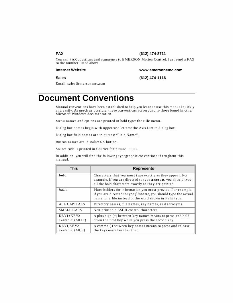
Document ConventionsManual conventions have been established to help you learn to use this manual quickly and easily. As much as possible, these conventions correspond to those found in other Microsoft Windows documentation.
Menu names and options are printed in bold type: the File menu.
Dialog box names begin with uppercase letters: the Axis Limits dialog box.
Dialog box field names are in quotes: “Field Name”.
Button names are in italic: OK button.
Source code is printed in Courier font: Case ERMS.
In addition, you will find the following typographic conventions throughout this manual.
This Represents
bold Characters that you must type exactly as they appear. For example, if you are directed to type a:setup, you should type all the bold characters exactly as they are printed.
italic Place holders for information you must provide. For example, if you are directed to type filename, you should type the actual name for a file instead of the word shown in italic type.
ALL CAPITALS Directory names, file names, key names, and acronyms.
SMALL CAPS Non-printable ASCII control characters.
KEY1+KEY2example: (Alt+F)
A plus sign (+) between key names means to press and hold down the first key while you press the second key.
KEY1,KEY2 example: (Alt,F)
A comma (,) between key names means to press and release the keys one after the other.
v
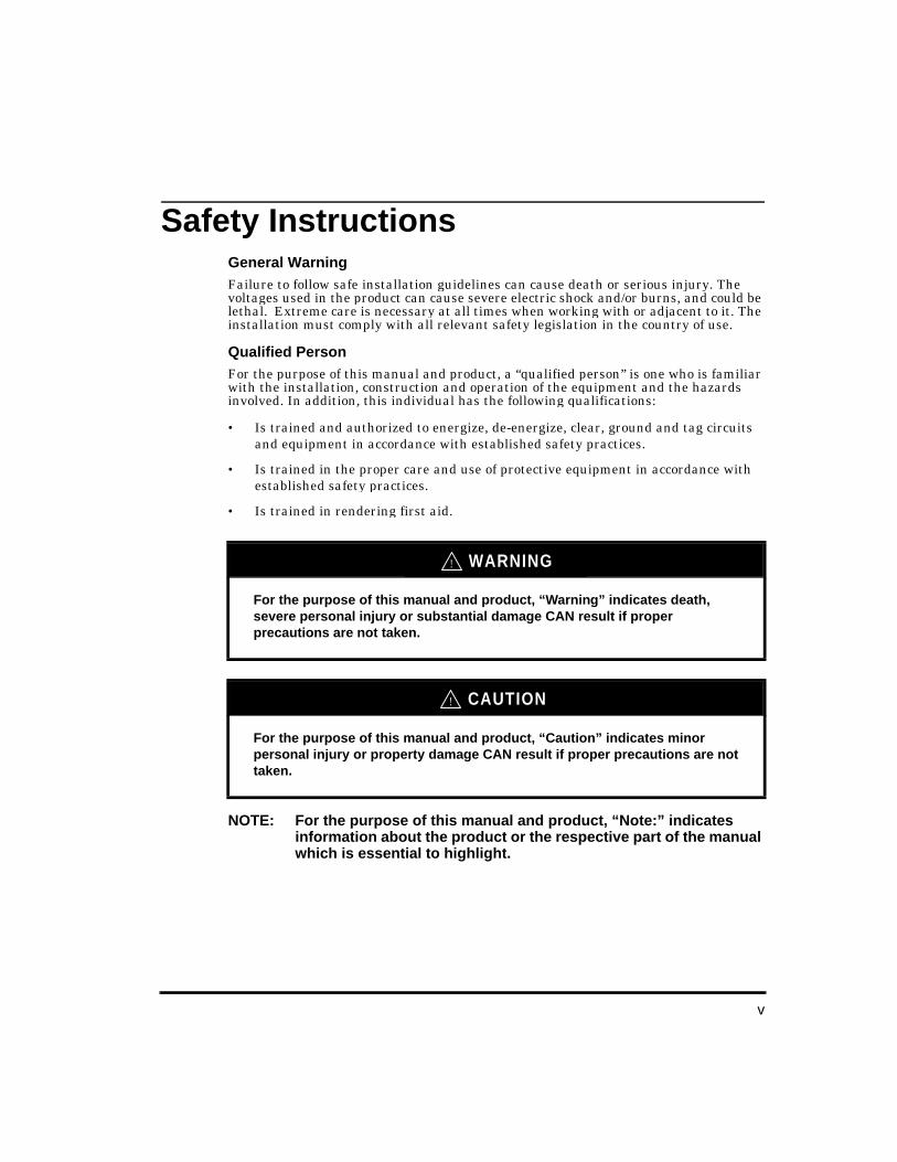
Safety InstructionsGeneral WarningFailure to follow safe installation guidelines can cause death or serious injury. The voltages used in the product can cause severe electric shock and/or burns, and could be lethal. Extreme care is necessary at all times when working with or adjacent to it. The installation must comply with all relevant safety legislation in the country of use.
Qualified PersonFor the purpose of this manual and product, a “qualified person” is one who is familiar with the installation, construction and operation of the equipment and the hazards involved. In addition, this individual has the following qualifications:
• Is trained and authorized to energize, de-energize, clear, ground and tag circuits and equipment in accordance with established safety practices.
• Is trained in the proper care and use of protective equipment in accordance with established safety practices.
• Is trained in rendering first aid.
NOTE: For the purpose of this manual and product, “Note:” indicates information about the product or the respective part of the manual which is essential to highlight.
For the purpose of this manual and product, “Warnin g” indicates death, severe personal injury or substantial dama ge CAN result if proper precautions are not taken.
For the purpose of this manual and product, “Caution” indicates minor personal injury or property dama ge CAN result if proper precautions are not taken.
WARNING!
CAUTION!
vii
IntroductionWelcome . . . . . . . . . . . . . . . . . . . . . . . . . . . . . . . . . . . . 1About this Manual . . . . . . . . . . . . . . . . . . . . . . . . . . . . 1
How this Manual is Organized . . . . . . . . . . . . . . . 1Reference Materials . . . . . . . . . . . . . . . . . . . . . . . 3OIT Models Supported . . . . . . . . . . . . . . . . . . . . . 4PLC Models Supported . . . . . . . . . . . . . . . . . . . . . 4
Gettin g StartedWhat You Need . . . . . . . . . . . . . . . . . . . . . . . . . . . . . . 5Installing OITware-200 . . . . . . . . . . . . . . . . . . . . . . . . 6Creating an OITware-200 Project . . . . . . . . . . . . . . . . 6
Configure the Communication Settings. . . . . . . . 7Configure the Status Coils . . . . . . . . . . . . . . . . . . 8Configure the Message Request and Current Message Registers . . . . . . . . . . . . . . . . . . . . . . . . . 9Save the Project . . . . . . . . . . . . . . . . . . . . . . . . . . . 14Configure the User-Definable Keys . . . . . . . . . . . 15Configure Screen #1 as the Startup Screen . . . . . 16Configure Screen #2 as a Message with a PLC Register Monitor . . . . . . . . . . . . . . . . . . . . . . . . . . 17Configure Function Key #1 to Display Screen #2 . . . . . . . . . . . . . . . . . . . . . . . . . . . . . . . . 20
Downloading an OITware-200 Project . . . . . . . . . . . . 21Connect the OIT to the PC . . . . . . . . . . . . . . . . . . 21Place the OIT in Download/Upload Mode . . . . . . 21Transfer the OITware-200 Project . . . . . . . . . . . . 23
Verifying the OIT is Operational . . . . . . . . . . . . . . . . 25OIT Power Up . . . . . . . . . . . . . . . . . . . . . . . . . . . . 25
Operational OverviewMessage Request Register (MRR) . . . . . . . . . . . . 29Message Request Sequence. . . . . . . . . . . . . . . . . . 30Enhanced MRR Features . . . . . . . . . . . . . . . . . . . 32
Current Message Register (CMR). . . . . . . . . . . . . . . . 33
Table of Contents
OIT-3165 Operator In-

viii
OIT-3165 Operator Interface Reference Manual
Key Coils . . . . . . . . . . . . . . . . . . . . . . . . . . . . . . . . 33Function Key and Screen Dependent Function Key Coils . . . . . . . . . . . . . . . . . . . . . . . . . . . . . . . . 35Status Coils . . . . . . . . . . . . . . . . . . . . . . . . . . . . . . 38Register Monitoring . . . . . . . . . . . . . . . . . . . . . . . 43Performance Considerations . . . . . . . . . . . . . . . . 43
Stored ScreensMessage Screens . . . . . . . . . . . . . . . . . . . . . . . . . . . . . 47Recipe Screens. . . . . . . . . . . . . . . . . . . . . . . . . . . . . . . 48Alarm Screens . . . . . . . . . . . . . . . . . . . . . . . . . . . . . . . 53Menu Screens . . . . . . . . . . . . . . . . . . . . . . . . . . . . . . . 56Help Screens . . . . . . . . . . . . . . . . . . . . . . . . . . . . . . . . 59Screen Features. . . . . . . . . . . . . . . . . . . . . . . . . . . . . . 60
Blinking Characters . . . . . . . . . . . . . . . . . . . . . . . 60Special Characters . . . . . . . . . . . . . . . . . . . . . . . . 61Screen Chain. . . . . . . . . . . . . . . . . . . . . . . . . . . . . 62Help Screen . . . . . . . . . . . . . . . . . . . . . . . . . . . . . . 63Horizontal Scrolling . . . . . . . . . . . . . . . . . . . . . . . 63Beep on Display . . . . . . . . . . . . . . . . . . . . . . . . . . 64Startup Screen . . . . . . . . . . . . . . . . . . . . . . . . . . . 65Timed Display. . . . . . . . . . . . . . . . . . . . . . . . . . . . 65
PLC Register MonitorsPLC Register Monitor Formats . . . . . . . . . . . . . . . . . 70
Signed . . . . . . . . . . . . . . . . . . . . . . . . . . . . . . . . . . 70Decimal . . . . . . . . . . . . . . . . . . . . . . . . . . . . . . . . . 71Long. . . . . . . . . . . . . . . . . . . . . . . . . . . . . . . . . . . . 714-Digit BCD. . . . . . . . . . . . . . . . . . . . . . . . . . . . . . 728-Digit BCD. . . . . . . . . . . . . . . . . . . . . . . . . . . . . . 721/0 Coil. . . . . . . . . . . . . . . . . . . . . . . . . . . . . . . . . . 73On/Off Coil . . . . . . . . . . . . . . . . . . . . . . . . . . . . . . 73Bank 8 . . . . . . . . . . . . . . . . . . . . . . . . . . . . . . . . . . 74Bank 16 . . . . . . . . . . . . . . . . . . . . . . . . . . . . . . . . . 74Message Stack Size. . . . . . . . . . . . . . . . . . . . . . . . 74Alarm Stack Size . . . . . . . . . . . . . . . . . . . . . . . . . 75ASCII Char . . . . . . . . . . . . . . . . . . . . . . . . . . . . . . 75ASCII String . . . . . . . . . . . . . . . . . . . . . . . . . . . . . 76
PLC Register Monitor Attributes. . . . . . . . . . . . . . . . 77Number of Digits . . . . . . . . . . . . . . . . . . . . . . . . . 77Decimal Location . . . . . . . . . . . . . . . . . . . . . . . . . 77
ix
Commas . . . . . . . . . . . . . . . . . . . . . . . . . . . . . . . . . 78Linear Scaling . . . . . . . . . . . . . . . . . . . . . . . . . . . . 78Leading Zeros . . . . . . . . . . . . . . . . . . . . . . . . . . . . 82Hide Data Entry . . . . . . . . . . . . . . . . . . . . . . . . . . 82ASCII Text . . . . . . . . . . . . . . . . . . . . . . . . . . . . . . . 83Left/Right Justification . . . . . . . . . . . . . . . . . . . . . 83Inc/Dec . . . . . . . . . . . . . . . . . . . . . . . . . . . . . . . . . . 84Low/High Limits . . . . . . . . . . . . . . . . . . . . . . . . . . 84Set Points . . . . . . . . . . . . . . . . . . . . . . . . . . . . . . . . 85
Displayin g Stored ScreensStartup Screen . . . . . . . . . . . . . . . . . . . . . . . . . . . . . . . 89PLC Screen Request . . . . . . . . . . . . . . . . . . . . . . . . . . 89
MRR–Value . . . . . . . . . . . . . . . . . . . . . . . . . . . . . . 90MRR–Bit Position . . . . . . . . . . . . . . . . . . . . . . . . . 90Configuring the MRR without Enhanced Features . . . . . . . . . . . . . . . . . . . . . . . . . . . . . . . . . 90Configuring the MRR with Enhanced Features . 91
Function Keys . . . . . . . . . . . . . . . . . . . . . . . . . . . . . . . 94Menu Selection. . . . . . . . . . . . . . . . . . . . . . . . . . . . . . . 94Message or Menu Chain — Page Up and Page Down Keys. . . . . . . . . . . . . . . . . . . . . . . . . . . . . . 95Screen Stack — Last Msg and Next Msg Keys . . . . . 95
Help Key . . . . . . . . . . . . . . . . . . . . . . . . . . . . . . . . 98Screen Saver . . . . . . . . . . . . . . . . . . . . . . . . . . . . . 98Set Points . . . . . . . . . . . . . . . . . . . . . . . . . . . . . . . . 100
Key TypesFunction Keys . . . . . . . . . . . . . . . . . . . . . . . . . . . . . . . 101
Passwords . . . . . . . . . . . . . . . . . . . . . . . . . . . . . . . 101Global Function Keys . . . . . . . . . . . . . . . . . . . . . . 103Screen Dependent Function Keys. . . . . . . . . . . . . 105
Control Keys. . . . . . . . . . . . . . . . . . . . . . . . . . . . . . . . . 109Alarm Acknowledge. . . . . . . . . . . . . . . . . . . . . . . . 109Arrow . . . . . . . . . . . . . . . . . . . . . . . . . . . . . . . . . . . 109Delta+ and Delta- . . . . . . . . . . . . . . . . . . . . . . . . . 109Help . . . . . . . . . . . . . . . . . . . . . . . . . . . . . . . . . . . . 110Last Message and Next Message . . . . . . . . . . . . . 110Page Up and Page Down. . . . . . . . . . . . . . . . . . . . 110Setup . . . . . . . . . . . . . . . . . . . . . . . . . . . . . . . . . . . 111Toggle . . . . . . . . . . . . . . . . . . . . . . . . . . . . . . . . . . . 111
x
OIT-3165 Operator Interface Reference Manual
Edit Keys . . . . . . . . . . . . . . . . . . . . . . . . . . . . . . . . . . . 111Clear . . . . . . . . . . . . . . . . . . . . . . . . . . . . . . . . . . . 111Enter . . . . . . . . . . . . . . . . . . . . . . . . . . . . . . . . . . . 112Numeric Keys . . . . . . . . . . . . . . . . . . . . . . . . . . . . 112
Control, Edit and Numeric Key Coils . . . . . . . . . . . . 113
Confi gurin g the User-Definable KeypadUsing the Default Keypad Template . . . . . . . . . . . . . 117Using a Predefined Keypad Template . . . . . . . . . . . . 118
OIT3165 Predefined Keypad Templates . . . . . . . 119Creating Your Own Keypad . . . . . . . . . . . . . . . . . . . . 120
Choose the Keys . . . . . . . . . . . . . . . . . . . . . . . . . . 120Arrange the Keys . . . . . . . . . . . . . . . . . . . . . . . . . 121
Configure the Keypad . . . . . . . . . . . . . . . . . . . . . . . . . 122
Other OIT Operatin g ModesSetup Mode . . . . . . . . . . . . . . . . . . . . . . . . . . . . . . . . . 125
UtilitiesRead Project from OIT . . . . . . . . . . . . . . . . . . . . . . . . 129Export Project to OIT . . . . . . . . . . . . . . . . . . . . . . . . . 130
Extended Character Sets
Slide-in Le gend TemplatesBlank Legends for Photocopying . . . . . . . . . . . . . . . . 133Dimensions for Computer Generated Legends . . . . . 135
Troubleshootin gDisplay Brightness and Viewing Angle . . . . . . . . . . . 137OIT Operation . . . . . . . . . . . . . . . . . . . . . . . . . . . . . . . 137OITware-200 . . . . . . . . . . . . . . . . . . . . . . . . . . . . . . . . 138OIT to PLC Communication . . . . . . . . . . . . . . . . . . . . 139Alarms . . . . . . . . . . . . . . . . . . . . . . . . . . . . . . . . . . . . . 142

xi
Hardware InstallationControl Panel Design Guidelines . . . . . . . . . . . . . . . . 145
Control Panel Grounding . . . . . . . . . . . . . . . . . . . 145Power Supply Selection. . . . . . . . . . . . . . . . . . . . . 146OIT Cable Routing. . . . . . . . . . . . . . . . . . . . . . . . . 147Other Steps to Improve Noise Immunity. . . . . . . 147
OIT Installation . . . . . . . . . . . . . . . . . . . . . . . . . . . . . . 147Create Custom Slide-In Legend . . . . . . . . . . . . . . 148Prepare Panel for OIT Mounting . . . . . . . . . . . . . 148Mount OIT to Panel. . . . . . . . . . . . . . . . . . . . . . . . 150Connect OIT to Power . . . . . . . . . . . . . . . . . . . . . . 151Connect OIT to PLC/Host . . . . . . . . . . . . . . . . . . . 151
OIT Configuration Wiring . . . . . . . . . . . . . . . . . . . . . . 153Connect OIT to PC for Configuration. . . . . . . . . . 153
Custom Keypad Slide-In Legends. . . . . . . . . . . . . . . . 155Predefined Keypad Templates . . . . . . . . . . . . . . . 156Blank Legend for Photocopying . . . . . . . . . . . . . . 157Installing a Slide-In Legend . . . . . . . . . . . . . . . . . 159
OIT-3165 Hardware Specifications. . . . . . . . . . . . . . . 160OIT-3165 Dimensions . . . . . . . . . . . . . . . . . . . . . . . . . 162
PLC Protocol GuidePLC to OIT Communications Settings . . . . . . . . . . . . 163Memory Map Accessible by the OITs . . . . . . . . . . . . . 167Using Various Memory Ranges. . . . . . . . . . . . . . . . . . 167
Cable Dia gramsE Series Drives Cables. . . . . . . . . . . . . . . . . . . . . . . . . 171AXIMA Cables . . . . . . . . . . . . . . . . . . . . . . . . . . . . . . . 172Cable Wiring Diagrams . . . . . . . . . . . . . . . . . . . . . . . . 173
OIT-PC-232-XXX Cable. . . . . . . . . . . . . . . . . . . . . 173OIT-EN-232-XXX Cable . . . . . . . . . . . . . . . . . . . . 173OIT-PC-485-XXX Cable. . . . . . . . . . . . . . . . . . . . . 174OIT-AX-485-XXX Cable . . . . . . . . . . . . . . . . . . . . 174

1
Introduction
Welcome Welcome to EMERSON Motion Control’s’ OIT-3165 Operator Interface Terminal for use with Programmable Logic Controllers (PLCs). This powerful family of operator interface terminals was designed to provide the human-machine interface in industrial applications. This manual explains how the OIT-3165 Operator Interface Terminal operates as well as how to implement the many available features using the OITware-200 Configuration Software.
NOTE: In this manual the term “PLC” refers to either a PLC, Motion Controller or Servo Drive
NOTE: The OITware-200 Configuration Software is a product of Maple Systems, Inc.
About this Manual
How this Manual is Or ganizedThis manual is divided into the following major sections
Introduction
This section introduces you to the OIT reference materials.
Getting Started
This section describes how to setup the OIT.
Operational Overview
This section is a detailed overview of the OIT and the relationship with the EMERSON products.
OIT-3165 Operator In-
2
OIT-3165 Operator Interface Reference Manual
Stored Screens
This section gives a detailed description of the various screens used by the OIT.
PLC Register Monitors
This section gives a detailed description of how to monitor PLC registers and coils using the OIT.
Displaying Stored Screens
This section gives a description of displaying the various screens used on the OIT.
Key Types
This section gives a detailed description of the various key types used by the OIT.
Configuring the User-Definable Keypad
This section gives a detailed description of the user-definable keypad used by the OIT.
Other OIT Operating Modes
This section gives a detailed description of the Setup Mode of the OIT.
Utilities
This section gives a description of the various utilities used by the OIT, including Read Project and Export Project.
Extended Character Sets
This section is for reference of the extended character sets available.
Slide-in Legend Templates
This section provides diagrams for the creation of the slide-in legends.
3
Introduction
Troubleshooting
This section provides you with guidelines and hints on troubleshooting various problems that may be encountered during setup and operation of your OIT.
Hardware Installation
This section gives a detailed description of the the setup and installation of the hardware for the OIT.
PLC Protocol Guide
This section gives a detailed description of the various PLC protocols used by the OIT.
Cables
This section gives a detailed description of the various cables used by the OIT, E Series drives and AXIMA multi-axis controllers.
Reference MaterialsThe documentation for your OIT-3165 Operator Interface Terminal consists of:
• OIT-3165 Operator Interface Installation Manual P/N 400520-02 (shipped with each OIT) — Covers the installation requirements of your specific OIT-3165 Operator Interface Terminal.
• OIT-3165 Operator Interface Reference Manual P/N 400520-01 (shipped with OITware-200) — Covers the general operation and features of the OIT-3165 Operator Interface Terminal.
• OITware-200 Online Help — Covers the operation of OITware-200.

4
OIT-3165 Operator Interface Reference Manual
OIT Models Supported OITware-200 v3.00 supports the following OIT models:
The OIT-5400-A00 is not supported in v3.00; it requires v2.03 or earlier.
NOTE: The software supports all of the above, however EMERSON Motion Control only suports the OIT-3165-A00.
PLC Models Supported OITware-200 v3.00 supports many PLCs and controllers. To see a list of the supported PLCs and controllers:
1. Start OITware-200.
2. From the File menu, choose New. The New Project dialog box appears.
3. The “PLC Type” drop down list box displays the supported PLCs and controllers.
OIT-3160-A00 OIT-3250-B00 OIT-4400-A00
OIT-3160-B00 OIT-3600-A00 OIT-4400-B00
OIT-3165-A00 OIT-3600-B00 OIT-4450-A00
OIT-3175-A00 OIT-4160-A00 OIT-4450-B00
OIT-3200-A00 OIT-4160-B00 OIT-5400-B00
OIT-3200-B00 OIT-4165-A00
OIT-3250-A00 OIT-4175-A00
5
Gettin g StartedThe Getting Started chapter walks you through all the steps required to setup your OIT:
• What You Need • Installing OITware-200 • Creating an OITware-200 Project • Downloading an OITware-200 Project • Verifying the OIT is Operational
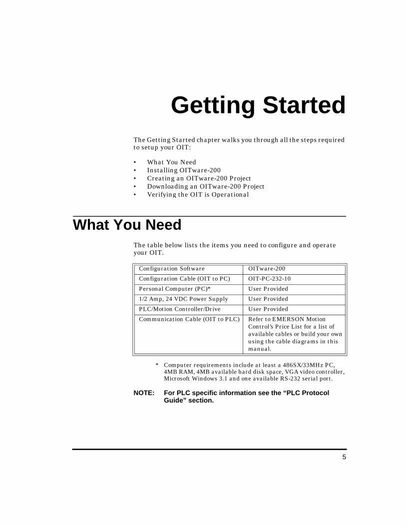
What You Need The table below lists the items you need to configure and operate your OIT.
* Computer requirements include at least a 486SX/33MHz PC, 4MB RAM, 4MB available hard disk space, VGA video controller, Microsoft Windows 3.1 and one available RS-232 serial port.
NOTE: For PLC specific information see the “PLC Protocol Guide” section.
Configuration Software OITware-200
Configuration Cable (OIT to PC) OIT-PC-232-10
Personal Computer (PC)* User Provided
1/2 Amp, 24 VDC Power Supply User Provided
PLC/Motion Controller/Drive User Provided
Communication Cable (OIT to PLC) Refer to EMERSON Motion Control’s Price List for a list of available cables or build your own using the cable diagrams in this manual.
OIT-3165 Operator In-

6
OIT-3165 Operator Interface Reference Manual
Installin g OITware-200 To install OITware-200: 1. Start Windows. If any applications are running, close them
before continuing.
2. Place the OITware-200 Setup Disk into your 3.5-inch floppy drive.
3. Windows95, 98 and NT4.0: From the Task Bar, choose Start, then Run. Windows 3.x: In Program Manager, from the File menu, choose Run.
4. Type a:\setup (substitute b for a if your 3.5-inch drive is configured as the b drive).
5. Choose the OK button.
6. Follow the instructions on your screen.
NOTE: When installation of OITware-200 is complete, your PC must be restarted before OITware-200 will operate correctly.
Creatin g an OITware-200 Project This step walks you through the creation of a basic OITware-200 project named SAMPLE.MAP. Once downloaded to the OIT, this basic configuration allows the OIT to connect to the PLC, display a startup message, and display a message containing one PLC register monitor when Function Key #1 is pressed.
1. Start OITware-200.
2. From the File menu, choose New. The New Project dialog box appears.
7
Getting Started
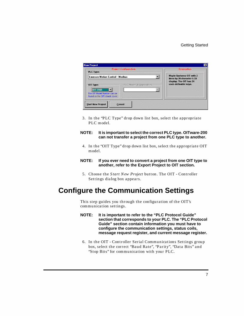
3. In the “PLC Type” drop down list box, select the appropriate PLC model.
NOTE: It is important to select the correct PLC type. OITware-200 can not transfer a project from one PLC type to another.
4. In the “OIT Type” drop down list box, select the appropriate OIT model.
NOTE: If you ever need to convert a project from one OIT type to another, refer to the Export Project to OIT section.
5. Choose the Start New Project button. The OIT - Controller Settings dialog box appears.
Confi gure the Communication Settin gs This step guides you through the configuration of the OIT’s communication settings.
NOTE: It is important to refer to the “PLC Protocol Guide” section that corresponds to your PLC. The “PLC Protocol Guide” section contain information you must have to configure the communication settings, status coils, message request register, and current message register.
6. In the OIT - Controller Serial Communications Settings group box, select the correct “Baud Rate”, “Parity”, “Data Bits” and “Stop Bits” for communication with your PLC.

8
OIT-3165 Operator Interface Reference Manual
7. In the Controller Access Settings group box, select the correct “Destination” for your PLC. Refer to the Controller Information Sheet that corresponds to your PLC for more information on these settings.
NOTE: Not all of these settings are required for all PLCs. OITware-200 will gray out the settings that do not apply to the PLC Type you selected in the New Project dialog box.
Confi gure the Status Coils This step walks you through the configuration of the Status coils. The Status coils are a block of 16 discrete coils in the PLC that are used by the OIT to communicate information to the PLC. All of the Status coils are optional and none of them are required for the PLC to request screens. For more information on the Status coils refer to the Status Coils section.
This OIT model allows the Status coils to be disabled. For this sample project, we will disable the Status coils.
To disable the Status coils, in the Status Coils group box, if the “Enable?” check box is checked unselect the “Enable?” check box.

9
Getting Started
Confi gure the Messa ge Request and Current Messa ge Registers
This step walks you through the configuration of the Message Request Register (MRR) and the Current Message Register (CMR).
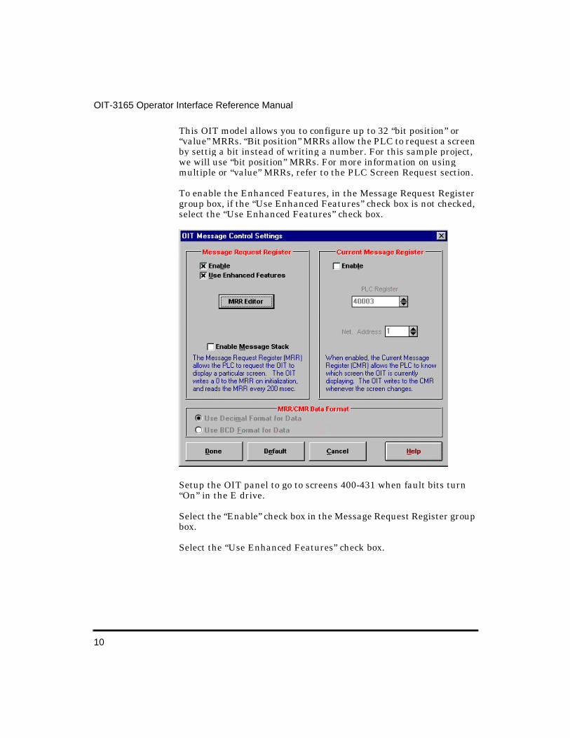
8. Choose the Configure Message Registers button. The OIT Message Control Settings dialog box appears.
The MRR is a data register in the PLC that allows the PLC to request screens for display on the OIT. The OIT writes a zero to the MRR on initialization and reads the MRR every 200 msec. For more information on the MRR, refer to the Message Request Register section.
This OIT model allows the MRR to be disabled. For this sample project, we will enable the MRR.
To enable the MRR, in the Message Request Register group box, if the “Enable” check box is not checked, select the “Enable” check box.
10
OIT-3165 Operator Interface Reference Manual
This OIT model allows you to configure up to 32 “bit position” or “value” MRRs. “Bit position” MRRs allow the PLC to request a screen by settig a bit instead of writing a number. For this sample project, we will use “bit position” MRRs. For more information on using multiple or “value” MRRs, refer to the PLC Screen Request section.
To enable the Enhanced Features, in the Message Request Register group box, if the “Use Enhanced Features” check box is not checked, select the “Use Enhanced Features” check box.
Setup the OIT panel to go to screens 400-431 when fault bits turn “On” in the E drive.
Select the “Enable” check box in the Message Request Register group box.
Select the “Use Enhanced Features” check box.
11
Getting Started
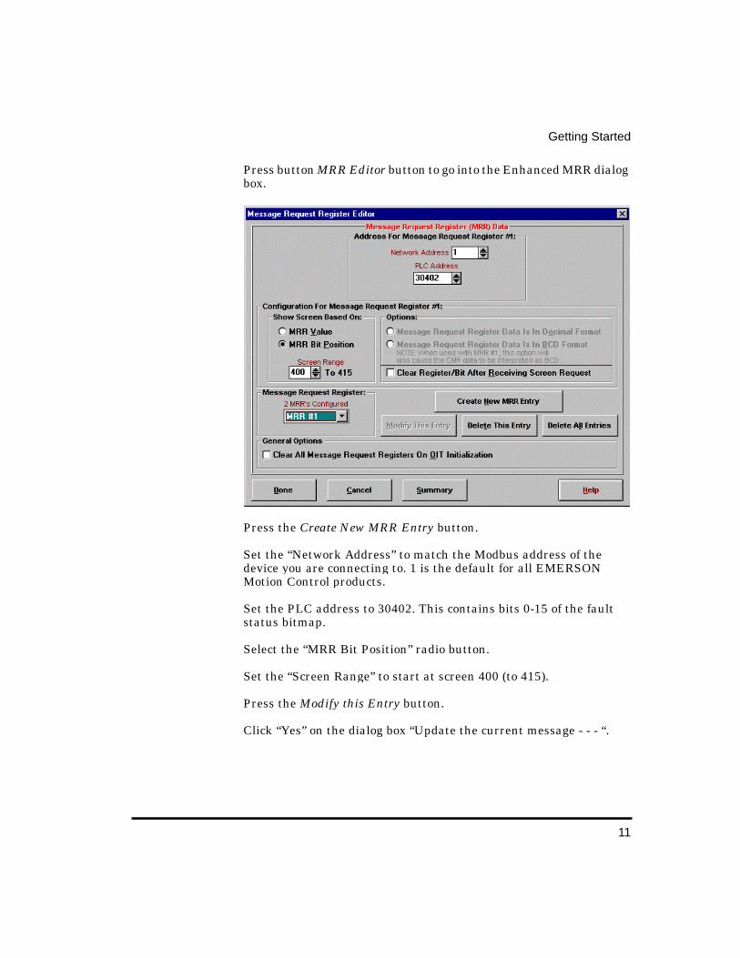
Press button MRR Editor button to go into the Enhanced MRR dialog box.
Press the Create New MRR Entry button.
Set the “Network Address” to match the Modbus address of the device you are connecting to. 1 is the default for all EMERSON Motion Control products.
Set the PLC address to 30402. This contains bits 0-15 of the fault status bitmap.
Select the “MRR Bit Position” radio button.
Set the “Screen Range” to start at screen 400 (to 415).
Press the Modify this Entry button.
Click “Yes” on the dialog box “Update the current message - - - “.
12
OIT-3165 Operator Interface Reference Manual
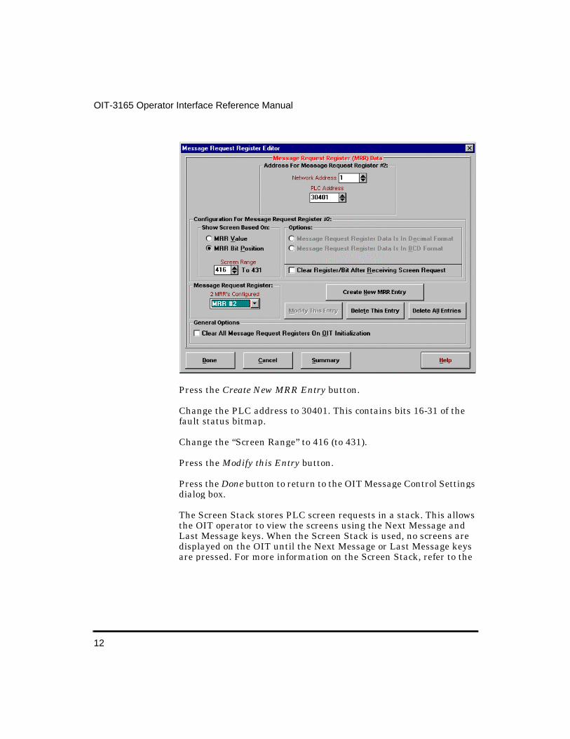
Press the Create New MRR Entry button.
Change the PLC address to 30401. This contains bits 16-31 of the fault status bitmap.
Change the “Screen Range” to 416 (to 431).
Press the Modify this Entry button.
Press the Done button to return to the OIT Message Control Settings dialog box.
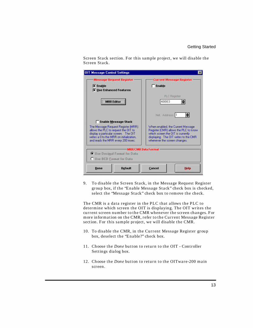
The Screen Stack stores PLC screen requests in a stack. This allows the OIT operator to view the screens using the Next Message and Last Message keys. When the Screen Stack is used, no screens are displayed on the OIT until the Next Message or Last Message keys are pressed. For more information on the Screen Stack, refer to the
13
Getting Started
Screen Stack section. For this sample project, we will disable the Screen Stack.
9. To disable the Screen Stack, in the Message Request Register group box, if the “Enable Message Stack” check box is checked, select the “Message Stack” check box to remove the check.
The CMR is a data register in the PLC that allows the PLC to determine which screen the OIT is displaying. The OIT writes the current screen number to the CMR whenever the screen changes. For more information on the CMR, refer to the Current Message Register section. For this sample project, we will disable the CMR.
10. To disable the CMR, in the Current Message Register group box, deselect the “Enable?” check box.
11. Choose the Done button to return to the OIT - Controller Settings dialog box.
12. Choose the Done button to return to the OITware-200 main screen.

14
OIT-3165 Operator Interface Reference Manual
Save the Project 1. From the File menu, choose Save As. The Save OIT Project File
As dialog box appears.
2. In the “File Name” text box, type sample.map.
3. Choose the OK button to save the project and return to the OITware-200 main screen.

15
Getting Started
Confi gure the User-Definable KeysThis step shows you how to access the User-Defined Key Editor and display the default keypad template. The OIT-3165 allows you to configure the keypad by selecting the keys you want and arranging them in any order. When you start an OITware-200 project, the default keypad template is automatically loaded. For more information on configuring the user-definable keys, refer to the Configuring the User-Definable Keypad section.
1. From the Configuration menu, choose Keyboard Settings, then choose User-Defined Key Editor. The User-Definable Key Assignment dialog box appears.
2. The default keypad template should be displayed. This is the screen you will use in the future to configure the keypad. To accept the default keypad template, choose the Done button to return to the OITware-200 main screen.
16
OIT-3165 Operator Interface Reference Manual
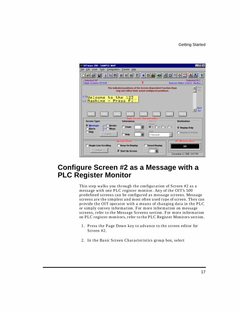
Confi gure Screen #1 as the Startup Screen This step walks you through the configuration of Screen #1 as the startup screen. The OIT stores up to 500 predefined screens. One of these predefined screens can be designated as the startup screen. The OIT automatically displays the startup screen whenever it is reinitialized. For more information on startup screens, refer to the Startup Screen section.
1. In the Screen Editor, type Welcome to the 123 and press ENTER.
2. In the Screen Editor, type Machine - Press F1 or press .
3. In the Basic Screen Characteristics group box, select
Screen Type — “Message” Extensions — none Alarms — n/a Destination — “Display Only”
4. In the Special Effects group box, select the “Start Up Screen” check box.
The OITware-200 main screen should look similar to the following screen.
17
Getting Started
Confi gure Screen #2 as a Messa ge with a PLC Register Monitor
This step walks you through the configuration of Screen #2 as a message with one PLC register monitor. Any of the OIT’s 500 predefined screens can be configured as message screens. Message screens are the simplest and most often used type of screen. They can provide the OIT operator with a means of changing data in the PLC or simply convey information. For more information on message screens, refer to the Message Screens section. For more information on PLC register monitors, refer to the PLC Register Monitors section.
1. Press the Page Down key to advance to the screen editor for Screen #2.
2. In the Basic Screen Characteristics group box, select
18
OIT-3165 Operator Interface Reference Manual
Screen Type — “Message” Extensions — none Alarms — n/a Destination — “Display Only”
3. In the Special Effects group box, none of the check boxes should be selected.
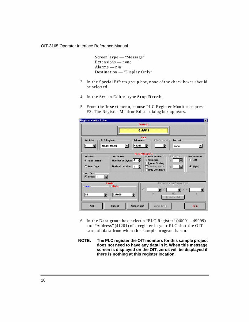
4. In the Screen Editor, type Stop Decel:.
5. From the Insert menu, choose PLC Register Monitor or press F3. The Register Monitor Editor dialog box appears.
6. In the Data group box, select a “PLC Register” (40001 - 49999) and “Address” (41201) of a register in your PLC that the OIT can pull data from when this sample program is run.
NOTE: The PLC register the OIT monitors for this sample project does not need to have any data in it. When this message screen is displayed on the OIT, zeros will be displayed if there is nothing at this register location.
19
Getting Started
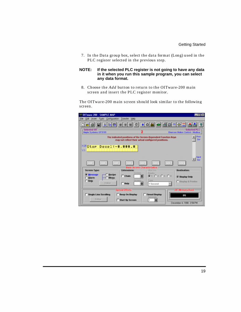
7. In the Data group box, select the data format (Long) used in the PLC register selected in the previous step.
NOTE: If the selected PLC register is not going to have any data in it when you run this sample program, you can select any data format.
8. Choose the Add button to return to the OITware-200 main screen and insert the PLC register monitor.
The OITware-200 main screen should look similar to the following screen.
20
OIT-3165 Operator Interface Reference Manual
Confi gure Function Key #1 to Display Screen #2
This step walks you through the configuration of Function Key #1 to display Screen #2. Each of the OIT’s function keys can be configured to display a screen or simulate a momentary or push-on/push-off switch.
1. From the Configuration menu, choose Keyboard Settings, then choose Function Key Editor or press F5. The Function Key Editor appears.
2. In the Assignment group box, select the “F1” radio button.
3. In the Attributes For Key #1 group box:
• In the “Action” drop down list box, select “Screen”.
• In the “Screen” scroll box, select 2.
4. Choose the Done button to return to the OITware-200 main screen.
5. From the File menu, choose Save.

21
Getting Started
Downloadin g an OITware-200 Project
Connect the OIT to the PC
Place the OIT in Download/Upload Mode
New OIT
If the OIT has never been configured, the following message appears when power is applied to the OIT:
OIT not Configured!Press Key for Dnload
Pressing any key on the OIT causes the OIT to enter download/upload mode. The following message appears:
Computer Comm ModeComputer must log-on
Existin g OIT
If your OIT has already been configured, follow these steps to place it in download/upload mode:
1. While applying power to the OIT, press and hold the bottom key on the right side of the keypad on the OIT while the “<<< Initializing >>>” message appears.

22
OIT-3165 Operator Interface Reference Manual
The following message should appear:
Setup Password:
2. Type the setup password and then press the bottom key on the right side of the keypad on the OIT. If there is no setup password, just press the bottom key on the right side of the keypad.
NOTE: You must start entering your password within 5 seconds, or the OIT exits setup mode.
The following message should appear:
Dn/Upload Mode? YES
3. Press the bottom key on the right side of the keypad on the OIT.
The following message should appear:
Computer Comm ModeComputer must log-on
The OIT is now in download/upload mode waiting for instructions from OITware-200.
If You Have Trouble Enterin g Download/Upload Mode
1. If the “<<< Initializing >>>” message is followed by “Attaching to PLC”, the OIT did not enter setup mode and you need to repeat Step 1.
2. If the OIT’s display remains blank and you hear a steady beeping, the OIT does not contain a complete project and is waiting in download/upload mode for OITware-200 to download a project. Since the OIT is already in download/upload mode, you should proceed to the next step, Transfer the OITware-200 Project.
23
Getting Started
Transfer the OITware-200 Project When you receive your OIT from the factory, it does not contain any information on how it is to operate. Therefore, the first time you download a project to the OIT you must also download the Operational Software. Downloading the Operational Software takes approximately three minutes to complete. Sending only the project file reduces the download time to approximately 30 seconds.
To download an OITware-200 project to the OIT:
1. Start OITware-200 and open your project.
NOTE: The OIT must be in download/upload mode to accept a project from OITware-200.
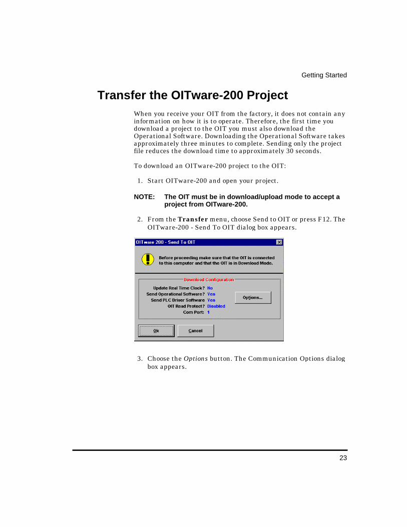
2. From the Transfer menu, choose Send to OIT or press F12. The OITware-200 - Send To OIT dialog box appears.
3. Choose the Options button. The Communication Options dialog box appears.

24
OIT-3165 Operator Interface Reference Manual
4. In the Download Only group box:
5. If you want to keep unauthorized users from reading the project in the OIT, in the Read Protect OIT group box, select the “Enable?” check box.
6. In the Upload & Download group box, select the “COM” port radio button that corresponds to the COM port the OIT is connected to. If you are unsure, choose the Auto Detect button.
For this condition Select this option button
The OIT does not contain the OIT Operational Software (new OITs).
Project, OIT Operational and OIT PLC Protocol Software
The OIT already contains the OIT Operational Software, but does not contain the OIT PLC Protocol Software.
Project and OIT PLC Protocol Software
The OIT already contains the OIT Operational and OIT PLC Protocol Software.
Project Only
25
Getting Started
NOTE: To use the Auto Detect feature, the OIT must be in download/upload mode and properly connected to the PC.
7. Choose the Done button to return to the OITware-200 - Send To OIT dialog box.
8. Choose the OK button to start the transfer.
When the transfer is complete, the OIT restarts. The OIT is now ready to communicate with the PLC.
Verifyin g the OIT is Operational Now that you have successfully downloaded an OITware-200 project to the OIT, you can connect the OIT to a PLC and verify that the OIT is operational.
To verify the OIT is operational:
1. Connect the OIT to a PLC. Please read your OIT Installation Manual before connecting the OIT to a PLC.
2. Apply power to the OIT and PLC. The OIT should go through the OIT power-up sequence defined below and then display the startup screen you configured in the Creating an OITware-200 Project section in this chapter.
OIT Power Up 1. The first thing the OIT does during power-up is display the
“<<< Initializing >>>” message and perform a self-test.
The OIT checks the condition of the firmware stored in the flash EPROM. If this check reveals that the firmware is lost or incomplete, the OIT displays a blank screen and beeps continuously.
The OIT tests the static RAM. If the test fails, the OIT displays the following message:
SRAM failure!!!
26
OIT-3165 Operator Interface Reference Manual
If the OIT determines that everything is in working order, the OIT displays the “Attaching to PLC” message and attempts to attach to the PLC.
2. The OIT attempts to communicate with the PLC. If not successful, the following message is displayed:
Can’t connect to PLCRetry in Progress!
3. The OIT attempts to write 0 to the MRRs (if feature not disabled in OITware-200). If not successful, the following message is displayed:
Cannot write to MsgRequest Register!
4. The OIT attempts to write 0 to the status coils (if feature not disabled in OITware-200). If not successful, the following message is displayed:
Cannot write to theStatus Coils!
5. The OIT attempts to write 1 to the Reset status coil (if status coils are enabled). If not successful, the following message is displayed:
Cannot set theReset Status Coil!
6. The OIT attempts to write 1 to the Alarm Stack Empty status coil (if status coils are enabled). If not successful, the following message is displayed:
Cannot set the AlarmEmpty Status Coil!
27
Getting Started
7. If the global function keys were configured for Default mode, the OIT attempts to write 0 to the function key coils. If the global function keys were configured for Retentive mode, the OIT attempts to read the function key coils. If not successful, the following message is displayed:
Cannot write to theFunction Key Coils!
8. If the OIT successfully competes the above steps, the following message is displayed:
Connecting to PLC!
9. The OIT beeps for one second and then displays the startup message configured in OITware-200. If no startup message was configured, the OIT displays a blank screen.

29
Operational OverviewThe OIT-3165 Operator Interface Terminal communicates with PLCs by using point-to-point serial communications to read from and write to the internal registers and coils of the PLC. Six sets of registers and coils located within the PLC’s internal memory are designated for special purposes: the Message Request Register, Current Message Register, Key coils, Status coils, Status LED coils, and Function Key LED coils.
Message Request Re gister (MRR) The MRR is a data register in the PLC that is continuously monitored by the OIT. When the PLC enters a decimal or BCD number into this register, the OIT:
• displays the screen that corresponds to that number (the screen can be a message, recipe, alarm or menu)
OIT-3165 Operator In-

30
OIT-3165 Operator Interface Reference Manual
• performs any special function associated with the screen (for example, an alarm screen might sound the OIT’s internal buzzer).
• and optionally sends the screen contents to a serial printer.
For example, you may want Screen #30 to be shown on the OIT whenever input coil X1 is turned “On”. Screen #30 might read: Oven Door is Open!!!
The relay ladder logic could be the following:
In this case, D500 is the MRR that the OIT has been configured to constantly monitor. When input coil X1 is activated, the PLC puts the decimal number 30 into the MRR. The OIT then sees the number 30 in the MRR and displays Screen #30.
Message Request Sequence
To display a screen, the following activities occur within the PLC and the OIT:
31
Operational Overview
• The PLC checks the message received status coil to ensure that the previous screen has already been processed by the OIT (optional).
• The PLC clears the message received status coil in preparation for writing a new screen number into the MRR (optional).
• The PLC writes the screen number into the MRR.
• The OIT polls the MRR for a new screen number once every 200 milliseconds.
• The OIT displays the screen, performing any special functions required by the screen contents (for example, if screen is an alarm, sound buzzer).
• The OIT sets the message received status coil to inform the PLC that the screen was properly displayed. If the status coils are disabled, the OIT does not set the message received status coil.
Once the OIT displays the screen requested in the MRR, the OIT must see a change in the number in the MRR in order to display another screen request from the PLC. For example, the PLC requests that Screen #5 be displayed. The OIT operator then presses Function Key #1 which displays Screen #30. The number 5 is still in the MRR, but since no change has occurred it is ignored by the OIT. The PLC can get the OIT to display the same screen twice without an intervening PLC screen request, by simply putting the number 0 into the MRR between the two identical screen requests. The OIT does not perform any action as a result of seeing the number 0 in the MRR, but it does note that a change occurred.
To use the MRR, the MRR must be enabled and have a PLC address assigned to it. For instructions on configuring the MRR, refer to the Configuring the Message Request and Current Message Registers section. During OIT power-up, the MRR is set to 0.
32
OIT-3165 Operator Interface Reference Manual
Enhanced MRR Features
Bit versus Value
The default MRR is a “value” MRR. Which means that the PLC calls screens by placing decimal or BCD numbers into the MRR. If you need the PLC to call a screen by setting a bit instead of writing a number, you need to use a “bit position” MRR. When using a bit position MRR, each bit in the specified MRR address corresponds to one of 16 stored screens in the OIT. To determine which stored screen to display, the OIT examines each bit in the MRR and then displays the stored screen that corresponds to the first set bit. For directions on configuring a bit position MRR, refer to the MRR–Bit Position section.
Multiple MRRs
Up to 32 MRRs can be created. For each bit position MRR, the PLC can request 16 different screens. With 32 bit position MRRs, the PLC can request all 500 OIT screens.
NOTE: Only one MRR is polled every 200 milliseconds. Therefore, if two MRRs are configured, it takes 400 milliseconds to poll them.
Clear MRR After Each PLC Screen Request
When the OIT polls the MRR, it only displays a screen if the value in the MRR is different from the last polled value. Therefore, if the PLC requests the same screen twice without requesting a different screen between the two requests, the OIT does not recognize the second screen request.
If your application requires that the PLC be able to request the same screen without using an intervening screen, you should activate the Clear Register/Bit After Receiving Screen Request option. When this option is enabled, the OIT sets the MRR to 0 after each PLC screen request. For directions on configuring this option, refer to the MRR-Bit Position section.
33
Operational Overview
Clear MRRs Durin g OIT Power-Up
Each time the OIT powers up, the OIT can be configured to clear the MRRs or leave the MRRs in their existing state. The default is to clear the MRRs. For directions on configuring this option, refer to the MRR-Bit Position section.
Current Messa ge Register (CMR) The OIT can be programmed to send the number representing the screen currently displayed on the OIT to a data register in the PLC called the Current Message Register. The OIT can be programmed to place numbers into the CMR in decimal or BCD format. This register can be used by the PLC to determine which screen is shown on the OIT. It might be used to determine if a specific alarm screen has been acknowledged by the OIT operator or it might be used to determine which screen in a chained sequence is currently being displayed. To use the CMR, it must be enabled and have a PLC address assigned to it in the OIT Message Control Settings dialog box in OITware-200 (from the Configuration menu, choose Message Control Settings).
Key Coils There are three types of coils in the PLC that are used to pass keypress data from the OIT to the PLC: Control Key coils, Function Key coils, and Screen Dependent Function Key coils.
Control Key Coils
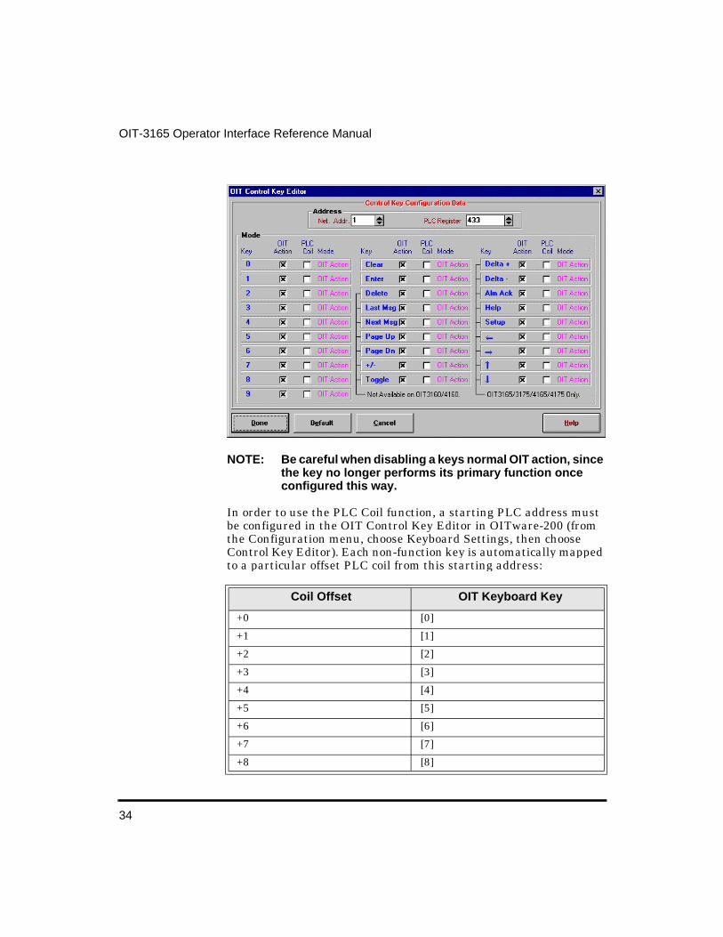
Each key on the OIT (except function keys) can be configured to perform its normal OIT action and/or set a PLC coil. If the OIT Action function is enabled, the key performs its normal OIT action (for example, the ALARM ACK key acknowledges the current alarm). If the PLC Coil function is enabled, pressing the key sets the corresponding Control Key coil in the PLC and releasing the key clears the coil. If both functions are enabled, the key performs its normal OIT action and sets/clears its Control Key coil in the PLC. If both functions are disabled, the key does nothing. Each non-function key can be configured independently using the OIT Control Key Editor in OITware-200 (from the Configuration menu, choose Keyboard Settings, then choose Control Key Editor).
34
OIT-3165 Operator Interface Reference Manual
NOTE: Be careful when disabling a keys normal OIT action, since the key no longer performs its primary function once configured this way.
In order to use the PLC Coil function, a starting PLC address must be configured in the OIT Control Key Editor in OITware-200 (from the Configuration menu, choose Keyboard Settings, then choose Control Key Editor). Each non-function key is automatically mapped to a particular offset PLC coil from this starting address:
Coil Offset OIT Keyboard Key
+0 [0]
+1 [1]
+2 [2]
+3 [3]
+4 [4]
+5 [5]
+6 [6]
+7 [7]
+8 [8]

35
Operational Overview
The PLC coil function is most often used to configure a non-function key to be used for some purpose defined by the system programmer. For instance, if the LAST MESSAGE and NEXT MESSAGE keys are not being used to display a history of messages, then they can be programmed as momentary switches. The PLC coil function can also be used to notify the PLC when the OIT operator has pressed one of the non-function keys.
Function Key and Screen Dependent Function Key Coils
Each global and screen dependent function key on the OIT has a corresponding coil in the PLC. When the function key is pressed, the coil in the PLC is activated. When the coil is cleared depends on how the function key is configured (for more information on clearing the coils, refer to the Function Key sections).
+9 [9]
+10 Clear
+11 Enter
+12 Delete
+13 Lst Msg
+14 Nxt Msg
+15 Page Up
+16 Page Dn
+17 +/-
+18 Toggle
+19 Delta +
+20 Delta -
+21 Alm Ack
+22 Help
+23 Setup
+24 Left Arrow
+25 Right Arrow
+26 Up Arrow
+27 Down Arrow
Coil Offset OIT Keyboard Key

36
OIT-3165 Operator Interface Reference Manual
The Function Key and Screen Dependent Function Key coil addresses allow each global or screen dependent function key to be assigned a unique PLC coil address. The Function Key coil address(es) is assigned in the Function Key Editor dialog box (from the Configuration menu, choose Keyboard Settings, then choose Function Key Editor or F5).
37
Operational Overview
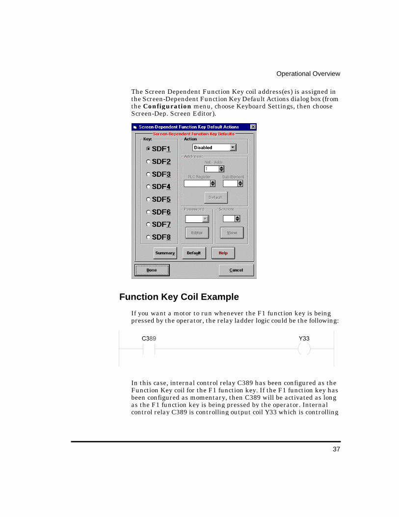
The Screen Dependent Function Key coil address(es) is assigned in the Screen-Dependent Function Key Default Actions dialog box (from the Configuration menu, choose Keyboard Settings, then choose Screen-Dep. Screen Editor).
Function Key Coil Example
If you want a motor to run whenever the F1 function key is being pressed by the operator, the relay ladder logic could be the following:
In this case, internal control relay C389 has been configured as the Function Key coil for the F1 function key. If the F1 function key has been configured as momentary, then C389 will be activated as long as the F1 function key is being pressed by the operator. Internal control relay C389 is controlling output coil Y33 which is controlling
38
OIT-3165 Operator Interface Reference Manual
a motor. Consequently, the motor runs whenever the operator is pressing the F1 function key.
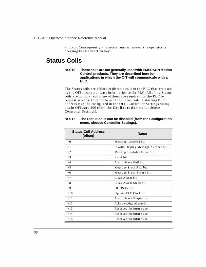
Status Coils NOTE: These coils are not generally used with EMERSON Motion
Control products. They are described here for applications in which the OIT will communicate with a PLC.
The Status coils are a block of discrete coils in the PLC that are used by the OIT to communicate information to the PLC. All of the Status coils are optional and none of them are required for the PLC to request screens. In order to use the Status coils, a starting PLC address must be configured in the OIT - Controller Settings dialog box in OITware-200 (from the Configuration menu, choose Controller Settings).
NOTE: The Status coils can be disabled (from the Configuration menu, choose Controller Settings).
Status Coil Address (offset)
Name
+0 Message Received bit
+1 Invalid Display Message Number bit
+2 Message/Keytable Error bit
+3 Reset bit
+4 Alarm Stack Full bit
+5 Message Stack Full bit
+6 Message Stack Empty bit
+7 Clear Alarm bit
+8 Clear Alarm Stack bit
+9 OIT Pulse bit
+10 Update PLC Clock bit
+11 Alarm Stack Empty bit
+12 Acknowledge Alarm bit
+13 Reserved for future use
+14 Reserved for future use
+15 Reserved for future use

39
Operational Overview
Message Received
The Message Received status coil is set by the OIT when a screen request has been successfully retrieved from the PLC. Therefore, it can be used by both the OIT and the PLC to perform handshaking when new screens are requested. For proper handshaking, the PLC should monitor this coil to determine if the last screen request sent to the OIT has been read. Additional screen requests should not be sent to the OIT until this coil has been set. It is the PLC’s responsibility to clear this coil before sending another screen request to the OIT. For more information on the message request sequence, refer to the Message Request Register section in this chapter.
NOTE: The PLC can ignore this coil if the OIT’s polling rate of the message request register (200 milliseconds) is faster than the PLC’s message update rate.
Sample Status Coil Addresses
GE Fanuc%M# Address
Allen-Bradley PLC-5B3:0 Address
Status Coil
945946947948949950951952953954955956957958 959960
B3:0/0B3:0/1B3:0/2B3:0/3B3:0/4B3:0/5B3:0/6B3:0/7B3:0/8B3:0/9B3:0/10B3:0/11B3:0/12B3:0/13B3:0/14B3:0/15
Message Received bitInvalid Display Message Number bitMessage/Keytable Error bitReset bitAlarm Stack Full bitMessage Stack Full bitMessage Stack Empty bitClear Alarm bitClear Alarm Stack bitOIT Pulse bitUpdate PLC Clock bitAlarm Stack Empty bitAcknowledge Alarm bitReserved for future useReserved for future useReserved for future use
40
OIT-3165 Operator Interface Reference Manual
Invalid Display Messa ge Number
The Invalid Display Message Number status coil is set by the OIT when the PLC requests a non-existent or empty screen. In systems designed for high integrity, the PLC should clear the coil, then activate an error coil indicating to the outside world that a problem exists so that the system programmer can correct the programming error either in the PLC or in the OIT.
Message/Keytable Error
The Message/Keytable Error status coil is set by the OIT when it detects invalid or corrupted data in the screens or keytable. For instance, this coil is set if a function key is pressed that has been configured to display a screen that does not exist. This coil is also set by the OIT when it detects that the message or function key databases have been contaminated. Since all of the configuration data is stored in FLASH EPROM, this error should never occur. However, in the event of a component failure, this coil indicates that an error has been detected in the OIT.
Reset
The Reset status coil is set by the OIT each time it powers up or performs a reinitialization due to exiting the OIT’s local setup menu. This can be used by the PLC to indicate that the OIT has performed a reset. The PLC can clear the coil and decide what to do with the information. Since the OIT may have experienced a power-down and will not know the current state of the system, we suggest that the PLC reset all I/O to a known neutral state before clearing this coil and continuing. For more information on the OIT’s power-up sequence, refer to the OIT Power-Up section.
Alarm Stack Full
The Alarm Stack Full status coil is set by the OIT when the OIT’s internal alarm stack is full. This feature allows the PLC to know that, although it may have sent several alarms to the OIT, nobody is acknowledging them. Additional alarms sent to the OIT cause the oldest alarm to be eliminated from the alarm stack. Typically, this coil is not set, but in the event that it is, a real problem exists: alarms are not being acknowledged by the operator, either because the alert was not heard or it is too short for an operator to recognize it. This coil allows the PLC to detect this problem and either issue a higher

41
Operational Overview
priority alarm that has a continuous alert tone or shut down critical parts of the system in case a hazardous potential exists. When the alarm stack is no longer full, the OIT clears this coil. For more information on alarms, refer to the Alarm Screens section in CHAPTER 3: Stored Screens.
Message Stack Full
The Message Stack Full status coil is set by the OIT when the screen stack feature is enabled and the OIT’s internal screen stack is full. This feature allows the PLC to know that, although it may have sent several screens to the OIT, nobody has read them yet. Therefore, this coil allows the PLC to take some sort of corrective action (such as sending an alarm, or not sending any more screens until this coil is cleared by the OIT). When the screen stack is no longer full, the OIT clears this coil. For more information on the screen stack, refer to the Screen Stack section.
Message Stack Empty
The Message Stack Empty status coil is set by the OIT when the screen stack feature is enabled and the OIT’s internal screen stack is empty. This feature could allow the PLC to send a burst of screen requests to the OIT, wait for the coil to be set, then send another set of screen requests. This offloads some of the overhead required by the PLC for interfacing with the operator. When the screen stack is no longer empty, the OIT clears this coil. For more information on the screen stack, refer to the Screen Stack section.
Clear Alarm
The Clear Alarm status coil is monitored by the OIT (every 10 seconds) to allow the PLC to clear the currently displayed alarm. If this coil is set by the PLC, the OIT cancels any alarm that is in progress, and continues normal operation. Then the OIT clears this coil to indicate to the PLC that the action has been carried out. This feature can be used to allow the PLC to cancel an alarm if the condition which caused the alarm no longer exists. However, care should be exercised when using this feature if multiple alarms are in the stack, as the PLC does not know which alarm it is clearing unless the CMR is used. For more information on the CMR, refer to the Current Message Register section. For more information on alarms, refer to the Alarm Screens section.
42
OIT-3165 Operator Interface Reference Manual
Clear Alarm Stack
The Clear Alarm Stack status coil is similar to the Clear Alarm status coil except that this coil allows the PLC to clear the entire stack of alarms, including the currently displayed one. This feature could be used to cancel all existing alarms on the OIT if the PLC performs a system-wide reset. For more information on alarms, refer to the Alarm Screens section.
NOTE: Any alarms in the stack are automatically cleared whenever the OIT is reinitialized.
OIT Pulse
The OIT Pulse status coil is pulsed by the OIT every 10 seconds. This allows the PLC to determine if the OIT is still communicating with the PLC.
Update PLC Clock
The Update PLC Clock status coil is set by the OIT when it starts sending new time and date information to the PLC and cleared by the OIT when it finishes. To ensure that the time and date are not currently being updated, the PLC should verify that this coil is not set before using the time and date information.
Alarm Stack Empty
The Alarm Stack Empty status coil is set by the OIT when the OIT initializes and when the OIT’s internal alarm stack is empty. When an alarm is received, the OIT clears this coil. This feature allows the PLC to determine if the plant floor operator has acknowledged all currently active alarms. Once all alarms have been acknowledged, the PLC may go into a “normal” operating state. For more information on alarms, refer to the Alarm Screens section.
Acknowled ge Alarm
The Acknowledge Alarm status coil is set by the OIT when the operator presses the ALARM ACK key to clear an alarm. This can be used to signal to the PLC that normal operation can begin again. It is the PLC’s responsibility to clear this coil once it has been set by the

43
Operational Overview
OIT. For more information on alarms, refer to the Alarm Screens section.
Register Monitorin g The PLC’s data and coil registers can be monitored, displayed, and updated by the OIT. This can be done by configuring the OIT screens to display PLC data and coil registers as embedded data fields (PLC register monitors). When the OIT displays a screen that contains a PLC register monitor, the OIT reads the specified PLC register address and then displays the data. If the PLC register monitor has been configured as read/write, when the operator changes the data in the PLC register monitor on the OIT’s display the OIT writes the change to the PLC register.
Up to 25 read-only or read/write PLC register monitors can be displayed in each OIT screen. If more than one PLC register monitor is on a screen, each one is updated by the OIT in continuous succession as rapidly as possible within the constraints of the particular PLC protocol and baud rate selected. Therefore, the update rate of each PLC register monitor is determined by the number of PLC register monitors on the screen and the PLC protocol being used (baud rate, protocol overhead, PLC program, etc.). For more information on PLC register monitors, refer to the PLC Register Monitors section.
Performance Considerations
OIT-3165 Memory Requirements
The OIT-3165 Operator Interface Terminal has FLASH memory for storing program code, protocol code, and system configuration information. This device is of the latest technology and permit easy firmware upgrades, protocol enhancements, and safe storage of important configuration data. Each OIT is capable of storing a maximum of 500 screens.
Data is stored dynamically to get the most out of the memory space allocated for configuration data. Memory is used only as necessary instead of allocating a certain number of bytes per message in the OIT. This means that the maximum number of screens which can actually be created is determined by how many characters the system programmer places into each screen, how many PLC register monitors are on each screen, and how many special attributes are
44
OIT-3165 Operator Interface Reference Manual
used (for example, blinking characters, scroll lines, etc.). Using this storage technique, it is very difficult to actually use all of the available memory in a single application.
The OIT Memory Used bar graph in the OITware-200 main screen keeps the system programmer informed of the remaining memory at all times.
System Speed
The OIT hardware and software were designed in such a way that system performance is only limited by the communications speed of the PLC, baud rate of the PLC, and the overhead associated with the PLC protocol driver (the number of characters over and above the actual data used for checksums, data formatting, etc.). In addition, some PLCs limit the amount of time spent communicating with external devices (such as OITs) based-on how much time is expended executing ladder rungs. This affects performance of the OIT update rate for PLC register monitors on the display. For more information, refer to the Controller Information Sheet that corresponds to your PLC.
45
Stored ScreensEach OIT-3165 Operator Interface Terminal is capable of storing up to 500 user-defined screens. There are five different types of stored screens; each providing a unique function.
To enhance communication, several screen features are available for use with stored screens. The following table lists the available features by screen type.
Screen Type Screen Function
Message Screens Convey information to the OIT operator and allow the OIT operator to change data in the PLC.
Recipe Screens Allow the OIT operator to setup and start a batch process.
Alarm Screens Notify the OIT operator of alarm conditions using a message and an audible alert.
Menu Screens Allow the OIT operator to branch off to other message, recipe, or menu screens.
Help Screens Convey information to the OIT operator specific to the screen being displayed when the OIT operator presses the HELP key.
Message Recipe Alarm Menu Help
Blinking Characters X X X X X
Special Characters X X X X X
Screen Chain X X
Help Screen X X X
Horizontal Scrolling X X X X
Beep on Display X X 9 Alerts X
Startup Screen X X X
Timed Display X X X
PLC Register Monitors X X X X
OIT-3165 Operator In-
46
OIT-3165 Operator Interface Reference Manual
This chapter explains how to configure the five types of stored screens and how to implement the available screen features using OITware-200. For more information on embedding PLC Register Monitors in stored screens, refer to the PLC Register Monitors section.
Once you start creating screens, you can use the Screen Utilization dialog box to see at a glance which screens have been configured. From the Tools menu, choose Screen Utilization. The Screen Utilization dialog box appears. When finished, choose the Go To Screen or Done button.

47
Stored Screens
Message Screens Message screens convey information to the OIT operator and through the use of PLC Register Monitors allow the OIT operator to change data in the PLC.
To create a message screen: 1. In the Screen Type group box, select the “Message” radio
button.
2. In the Screen Editor, enter the text to be displayed.
3. In the Screen Editor, insert any necessary PLC Register Monitors. For more information on embedding PLC Register Monitors, refer to the PLC Register Monitors section.
4. Configure any screen features (blinking, etc.) you want to use. For more information on configuring the available screen features, refer to the Screen Features section.
48
OIT-3165 Operator Interface Reference Manual
Recipe Screens Recipe screens allow the OIT operator to setup and start a batch process. Each recipe screen can include up to 20 preset ingredients that are not visible to the OIT operator as well as 25 operator controlled ingredients that are displayed and can be modified before being downloaded to the PLC. Each recipe screen also includes:
• An initiator, which is a single character in the bottom right corner of the recipe screen that the OIT operator must change from “N” to “Y” to download the recipe to the PLC.
• A gate coil, which is a PLC relay coil that the OIT uses to signal the PLC that the recipe has been downloaded and the batch process is ready to start (optional).
Recipe screens operate in the following manner:
49
Stored Screens
1. When a recipe screen is initially displayed, the initiator is set to “N” and the gate coil is set to “Off” (“Off” is configured by the system programmer to be either 0 or 1).
2. The OIT operator uses the arrow keys to navigate the recipe screen and alter the read/write PLC Register Monitors.
3. The OIT operator uses the arrow keys to move the cursor to the initiator, presses the TOGGLE key to change the initiator to “Y”, and then presses the ENTER key.
4. The OIT writes the preset values to the predefined PLC registers and sets the gate coil to “On” (“On” is configured by the system programmer to be either 0 or 1). By setting the gate coil on, the OIT tells the PLC that the recipe has been downloaded and the batch process is ready to start.
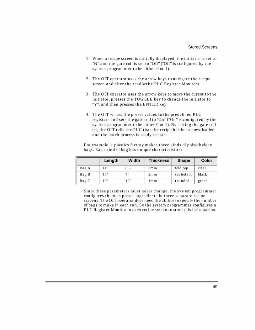
For example, a plastics factory makes three kinds of polyethylene bags. Each kind of bag has unique characteristics:
Since these parameters must never change, the system programmer configures them as preset ingredients in three separate recipe screens. The OIT operator does need the ability to specify the number of bags to make in each run. So the system programmer configures a PLC Register Monitor in each recipe screen to store this information.
Length Width Thickness Shape Color
Bag A 11” 8.5 3mm fold top clear
Bag B 15” 4” 2mm sealed top black
Bag C 10” 10” 1mm rounded green
50
OIT-3165 Operator Interface Reference Manual
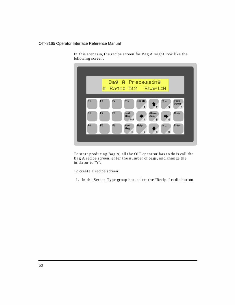
In this scenario, the recipe screen for Bag A might look like the following screen.
To start producing Bag A, all the OIT operator has to do is call the Bag A recipe screen, enter the number of bags, and change the initiator to “Y”.
To create a recipe screen:
1. In the Screen Type group box, select the “Recipe” radio button.

51
Stored Screens
2. In the Screen Type group box, choose the Editor button. The Recipe Editor dialog box appears. The Recipe Editor dialog box is divided into three sections, Register Data, Gate Data, and Recipe Presets List. The Register Data group box is used to enter the “Address”, “Format”, “Value” and “Description” of each preset ingredient. The Gate Coil group box is used to enable the gate coil, set the PLC address of the gate coil, and specify whether the “On” value of the gate coil is 0 or 1. The Recipe Presets List is used to list the preset ingredients that have been entered in the Register Data group box.

52
OIT-3165 Operator Interface Reference Manual
3. In the Register Data group box, enter each preset ingredient:
• In the “PLC Register” drop down list box, select the PLC register location.
• In the “Address” and “Sub-Element” scroll boxes, select the PLC register address.
• In the “Format” drop down list box, select the data format.
• In the “Value” scroll box, select the default value.
• In the “Description” text box, enter a description of this preset ingredient (up to 25 characters).
4. In the Gate Data group box, configure the gate coil:
• In the Gate Coil group box, select the “Enable” check box if you want to use the gate coil.
53
Stored Screens
• In the “Coil Address” and “Sub-Element” scroll boxes, select the PLC register address.
• In the Trigger group box, select the radio button that corresponds to the gate coil’s “On” state.
5. Choose the Done button to return to the Screen Editor.
6. In the Screen Editor, enter the text to be displayed.
7. In the Screen Editor, insert any necessary PLC Register Monitors. For more information on embedding PLC Register Monitors, refer to the PLC Register Monitors section.
8. Configure any screen features (blinking, etc.) you want to use. For more information on configuring the available screen features, refer to the Screen Features section.
Alarm Screens Alarm screens notify the OIT operator of alarm conditions using a message and an audible alert. The message text and the duration of the audible alert can be configured for each alarm screen. When the PLC requests an alarm screen:
• The prior screen is immediately replaced by the alarm.• The internal buzzer sounds.
Audible Alert Types• 1 Second• 5 seconds• 30 seconds• 60 seconds• Three beeps, once per second• Five beeps, twice per second• One beep per second• Two beeps per second• Continuous beep
Once an alarm screen is displayed, all other non-alarm screen requests are ignored until the OIT operator presses the ALARM
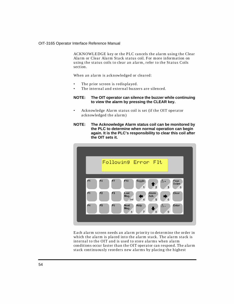
54
OIT-3165 Operator Interface Reference Manual
ACKNOWLEDGE key or the PLC cancels the alarm using the Clear Alarm or Clear Alarm Stack status coil. For more information on using the status coils to clear an alarm, refer to the Status Coils section.
When an alarm is acknowledged or cleared:
• The prior screen is redisplayed.• The internal and external buzzers are silenced.
NOTE: The OIT operator can silence the buzzer while continuing to view the alarm by pressing the CLEAR key.
• Acknowledge Alarm status coil is set (if the OIT operator acknowledged the alarm)
NOTE: The Acknowledge Alarm status coil can be monitored by the PLC to determine when normal operation can begin again. It is the PLC’s responsibility to clear this coil after the OIT sets it.
Each alarm screen needs an alarm priority to determine the order in which the alarm is placed into the alarm stack. The alarm stack is internal to the OIT and is used to store alarms when alarm conditions occur faster than the OIT operator can respond. The alarm stack continuously reorders new alarms by placing the highest
55
Stored Screens
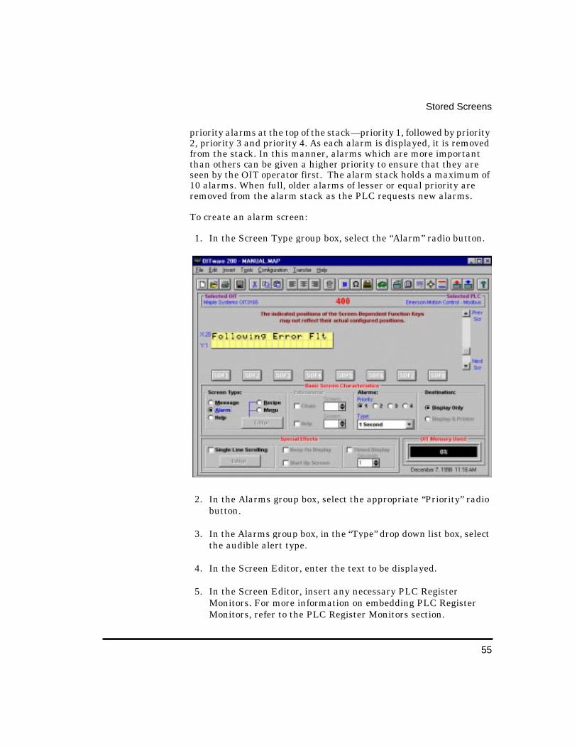
priority alarms at the top of the stack—priority 1, followed by priority 2, priority 3 and priority 4. As each alarm is displayed, it is removed from the stack. In this manner, alarms which are more important than others can be given a higher priority to ensure that they are seen by the OIT operator first. The alarm stack holds a maximum of 10 alarms. When full, older alarms of lesser or equal priority are removed from the alarm stack as the PLC requests new alarms.
To create an alarm screen:
1. In the Screen Type group box, select the “Alarm” radio button.
2. In the Alarms group box, select the appropriate “Priority” radio button.
3. In the Alarms group box, in the “Type” drop down list box, select the audible alert type.
4. In the Screen Editor, enter the text to be displayed.
5. In the Screen Editor, insert any necessary PLC Register Monitors. For more information on embedding PLC Register Monitors, refer to the PLC Register Monitors section.

56
OIT-3165 Operator Interface Reference Manual
6. Configure any screen features (blinking, etc.) you want to use. For more information on configuring the available screen features, refer to the Screen Features section.
Menu Screens Menu screens allow the OIT operator to branch off to other message, recipe, or menu screens by pressing the associated numeric key. Each menu screen can branch to as many as nine other screens using the 1 through 9 keys.
Sometimes it is difficult to fit descriptions for all nine menu options on one screen. When this happens, all you need to do is configure two or more menu screens and chain them together. Then each screen can have the same nine options, but the descriptions can be divided between the screens. For more information on chaining menu screens, refer to the Screen Chain section.
To create a menu screen:
1. In the Screen Type group box, select the “Menu” radio button.

57
Stored Screens
2. In the Screen Type group box, choose the Editor button. The Menu Editor dialog box appears. The Menu Editor dialog box is used to assign the numeric keys to other message, recipe or menu screens.

58
OIT-3165 Operator Interface Reference Manual
3. In the Screen Selection group box, select the screen to branch to for each numeric key.
NOTE: Any or all of the nine numeric keys can be used.
4. Choose the Done button, to return to the Screen Editor.
5. In the Screen Editor, enter the text to be displayed.
6. In the Screen Editor, insert any necessary PLC Register Monitors. For more information on embedding PLC Register Monitors, refer to the PLC Register Monitors section.
7. Configure any screen features (blinking, etc.) you want to use. For more information on configuring the available screen features, refer to the Screen Features section.
59
Stored Screens
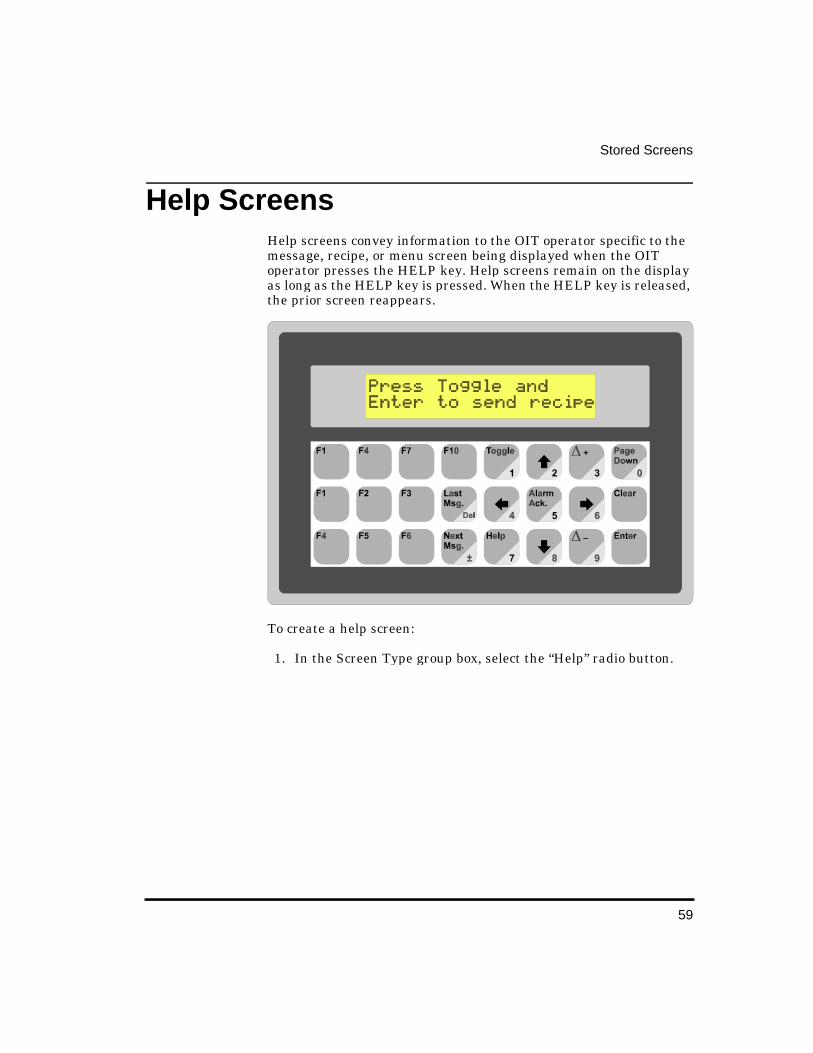
Help Screens Help screens convey information to the OIT operator specific to the message, recipe, or menu screen being displayed when the OIT operator presses the HELP key. Help screens remain on the display as long as the HELP key is pressed. When the HELP key is released, the prior screen reappears.
To create a help screen:
1. In the Screen Type group box, select the “Help” radio button.

60
OIT-3165 Operator Interface Reference Manual
2. In the Screen Editor, enter the text to be displayed.
3. Configure any screen features (blinking, etc.) you want to use. For more information on configuring the available screen features, refer to the Screen Features section.
Screen Features
Blinkin g Characters Each character in a message, recipe, alarm, menu or help screen (including text, special characters, and PLC Register Monitors) can be configured to blink. Those characters with the blink attribute enabled, will blink once per second for as long as the screen is displayed.
To configure a character to blink:

61
Stored Screens
1. In the Screen Editor, use the mouse to select the characters that you want to blink.
NOTE: You must select the entire PLC Register Monitor when configuring it to blink.
2. From the Edit menu, choose Blink or from the toolbar, choose the Blink button.
NOTE: Characters with the blink attribute enabled, will blink in the Screen Editor.
Special Characters The OIT-3165 Operator Interface Terminal has a set of extended characters that can be embedded into each stored screen. Refer to the Extended Character Set section to see the various extended character sets.
To insert a special character:
1. In the Screen Editor, position the cursor where you want to insert the special character.
2. From the Insert menu, choose Special Character or from the toolbar, choose the Insert Special Character button. The Insert Special Characters dialog box appears.
62
OIT-3165 Operator Interface Reference Manual
3. Using the arrow keys, select any special character.
4. Choose the Add To List button. The selected special character displays in the text box next to the Add To List button.
5. Choose the Done button to return to the OITware-200 main screen. The special character(s) that were displayed in the text box next to the Add To List button will be added to the cursors location in the Screen Editor.
Screen Chain Often, an event occurs which requires a message or menu be sent to the OIT operator that is longer than the space provided on one screen of the OIT. To compensate for the limited size of the OIT’s display, message or menu screens can be chained together so that they can be viewed in succession. When one of the chained screens is currently displayed, other screens that are chained to it can be displayed by using the PAGE UP and PAGE DOWN keys.
A message loop can be created by chaining the last screen in the chain to the first screen in the chain. In addition, a chained series of screens can be continuously displayed without any keypress or request from the PLC by configuring each screen in the chain for timed display. For more information on configuring screens for timed display, refer to the Timed Display section.
In the following example, Screen #1 is chained to Screen #5 which is chained to Screen #3.
When Screen #1 displays, a “->” symbol displays in the lower right corner of the screen. This symbol indicates that Screen #1 is chained to another screen. Pressing the PAGE DOWN key displays the next screen (Screen #5). Screen #5 displays with a “<->” symbol. This symbol indicates that the displayed screen is in the middle of a chained sequence. At this point, pressing the PAGE UP key displays the previous screen (Screen #1) and pressing the PAGE DOWN key displays the next screen (Screen #3). Screen #3 displays with a “<-” symbol. This symbol indicates that the displayed screen is the last
Screen #1 Screen #5 Screen #3
Gas Volume 22836 cfFlow Rate 15 cfm
Cooler Temp 50Motor ON
Oven Door CLOSEDFluid Temp 60°C
63
Stored Screens
screen of a chained sequence. At this point, pressing the PAGE UP key displays the previous screen (Screen #5).
To configure message/menu screen chains:
1. Create the message or menu screens using the Screen Editor.
NOTE: The lower right character in each chained screen is used to display the chain symbols and therefore is not available.
2. For each screen in the chain, in the Extensions group box, select the “Chain” check box and enter the screen number of the screen to link to.
Help Screen Each message, recipe, or menu screen can display one help screen when the HELP key is pressed. The help screen can be different for each message, recipe, or menu screen.
To link to a help screen:
1. In the Extensions group box, select the “Help” check box and enter the screen number of the help screen you want displayed when the OIT operator presses the HELP key.
Horizontal Scrollin g Each message, recipe, alarm, or menu screen can have a single line of up to 128 characters that scrolls horizontally. The scrolling line travels at the rate of two characters per second starting with a blank line and scrolling from the right side of the display. This line can be used to get the attention of the OIT operator, or to display a string of text that is longer than the number of characters in the display.
The Horizontal Scroll Rate is adjustable. From the OITware-200 main screen, choose the Configuration menu, then choose General Settings. The OIT General Settings dialog box appears.
In the Horiz. Scroll Rate group box, select the number, from 1 (scrools 1 character every 0.1 seconds) to 15 (scrolls 1 character every 1.5 seconds), that represents your desired scoll rate.
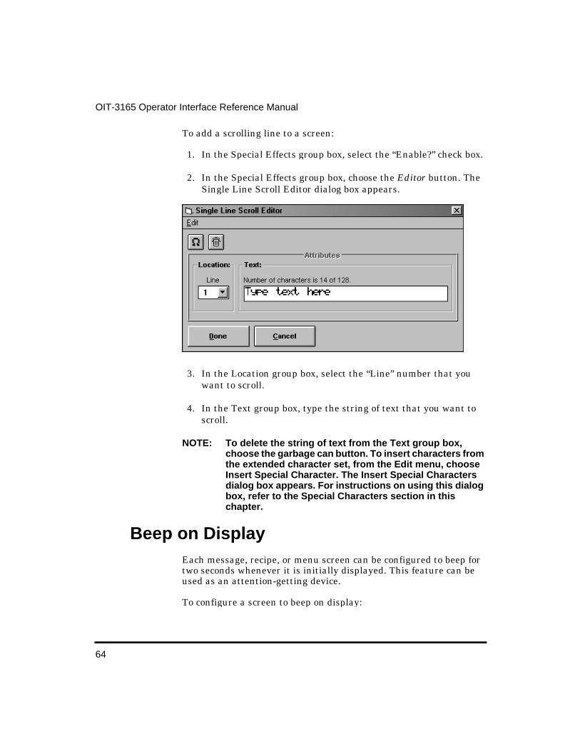
64
OIT-3165 Operator Interface Reference Manual
To add a scrolling line to a screen:
1. In the Special Effects group box, select the “Enable?” check box.
2. In the Special Effects group box, choose the Editor button. The Single Line Scroll Editor dialog box appears.
3. In the Location group box, select the “Line” number that you want to scroll.
4. In the Text group box, type the string of text that you want to scroll.
NOTE: To delete the string of text from the Text group box, choose the garbage can button. To insert characters from the extended character set, from the Edit menu, choose Insert Special Character. The Insert Special Characters dialog box appears. For instructions on using this dialog box, refer to the Special Characters section in this chapter.
Beep on Display Each message, recipe, or menu screen can be configured to beep for two seconds whenever it is initially displayed. This feature can be used as an attention-getting device.
To configure a screen to beep on display:

65
Stored Screens
1. In the Special Effects group box, select the “Beep on Display” check box.
Startup Screen One message, recipe, or menu screen can be designated as the startup screen. The startup screen automatically appears whenever the OIT is powered-up.
To configure a screen as the startup screen:
1. In the Special Effects group box, select the “Start Up Screen” check box.
Timed Display Normally, each screen remains on the display until another screen is displayed or the screen is cleared. However, the timed display attribute allows a message, recipe, or menu screen to be configured so that it displays for a set amount of time, 1 to 255 seconds, after which the prior screen is redisplayed. This could be used to display screens which should only be shown for a brief period of time.
If the screens in a message/menu chain are configured for timed display, each screen in the chain displays for the specified time and then the next screen in the chain is automatically displayed. This feature allows the system programmer to create a series of screens that can be continuously displayed without any keypress or request from the PLC.
NOTE: If the Screen Stack is enabled, then the timed display works differently. If several screens with a timed attribute are in the screen stack, each screen is displayed for the preset length of time, then the next screen in the stack is displayed. The last screen in the stack remains on the screen regardless of whether or not it is configured for a preset length of time.
To configure a screen for timed display:
1. In the Special Effects group box, select the “Timed Display” check box and enter the number of seconds the screen should be displayed.

67
PLC Register MonitorsThe PLC’s registers and coils can be monitored, displayed, and updated by the OIT. This is done by configuring the OIT screens to display PLC registers and/or coils as embedded data fields (PLC Register Monitors). When the OIT displays a screen that contains a PLC Register Monitor, the OIT reads the specified PLC register address and then displays the data. If the PLC Register Monitor has been configured as read/write, when the OIT operator changes the data in the PLC Register Monitor on the OIT’s display the OIT writes the change to the PLC register address.
A maximum of 25 “read-only” or “read/write” PLC Register Monitors can be displayed on each Message, Alarm, Recipe, or Menu screen (Menu screens only accept read only PLC Register Monitors). If more than one PLC Register Monitor is on a screen, each is updated by the OIT in continuous succession as rapidly as possible within the constraints of the particular PLC protocol and baud rate selected. Therefore, the update rate of each PLC Register Monitor is determined by the number of PLC Register Monitors on the screen and the PLC protocol being used (baud rate, protocol overhead, PLC program, etc.).
The arrow keys move the cursor from one read/write PLC Register Monitor to another. Each time one of the arrow keys is pressed, the cursor moves to the next closest read/write PLC Register Monitor in the direction of the pressed arrow key. When the cursor is located at one of the edges of the display, additional keypresses in the direction of the display edge cause the cursor to wrap around, from top to bottom, etc.
Once the cursor is positioned in the correct PLC Register Monitor, the OIT operator can:
• Press the TOGGLE key to alternate between “1” and “0” values in 1/0 Coil, On/Off Coil, or ASCII String PLC Register Monitor formats. The data is sent to the PLC immediately, so the OIT operator does not need to press the ENTER key.
OIT-3165 Operator In-
68
OIT-3165 Operator Interface Reference Manual
• Press the DELTA+ and DELTA- keys to “jog” or adjust the value in the PLC Register Monitor by preset increments. The data is sent to the PLC immediately, so the OIT operator does not need to press the ENTER key. The preset increment is determined by the system programmer. When the value in the PLC Register Monitor bumps against the preset low or high limits, an error message is displayed and the delta keys are ignored.
• Press the CLEAR key to clear the PLC Register Monitor’s contents and activate data entry mode. When data entry mode is activated, the PLC Register Monitor becomes blank and the cursor moves to the rightmost character position. The OIT operator can then enter a new value using the numeric keys on the OIT’s keypad. When finished, the OIT operator presses the ENTER key. If the value is within the preset low and high limits, the entry is accepted and immediately written to the PLC. If the value is outside the preset limits, an error message is displayed indicating that the entered value is out of range.
NOTE: When the OIT operator enters data into a PLC Register Monitor that has the adjustable decimal point enabled, the OIT operator does NOT enter the decimal point, but simply enters the raw number. Once the data is sent to the PLC, the correct decimal position is shown.
To insert a register monitor into a screen:
1. From the Insert menu, choose PLC Register Monitor or choose the PLC Register Monitor button from the toolbar. The Register Monitor Editor dialog box appears.

69
PLC Register Monitors
2. In the Data group box, select the “PLC Register”, “Address” and “Sub-Element” you want to monitor in the PLC.
3. In the Data group box, select the format that corresponds to the data format in the PLC register being monitored. For more information on the available formats, refer to the PLC Register Monitor Formats section.
4. Use the Field Attributes, Limits, and Linear Scaling Parameters group boxes, to configure the attributes for this PLC Register Monitor. For more information on the available attributes, refer to the PLC Register Monitor Attributes section.
To view existing register monitors:
1. In the Register Monitor Editor, choose the Screen List button or from the Tools menu, choose Register Monitor List. The Register Monitor List dialog box appears.
2. Choose the Done button to close the Register Monitor List dialog box.
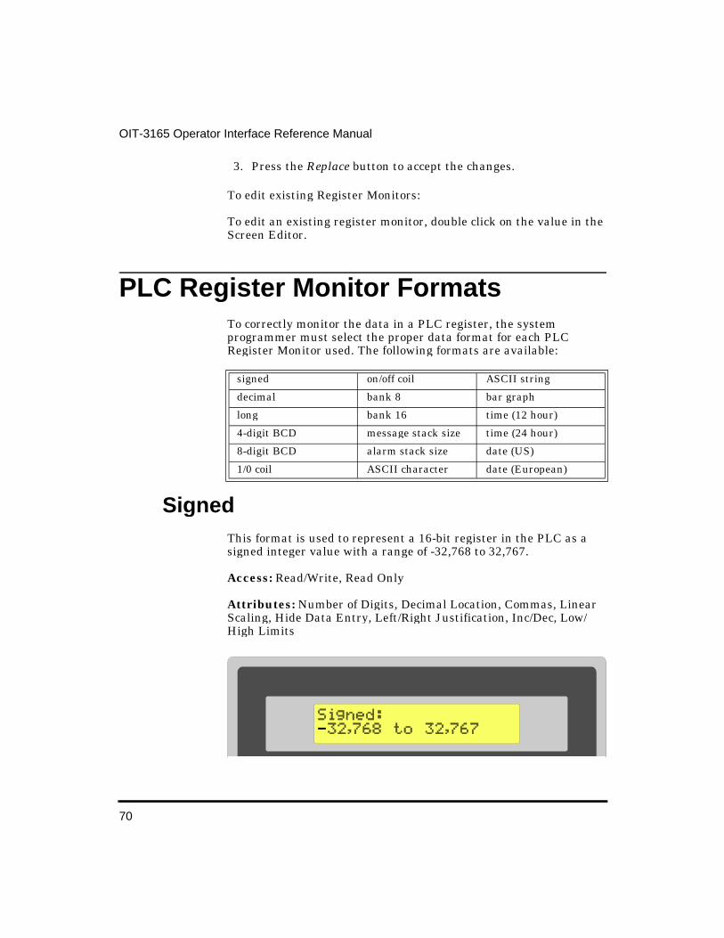
70
OIT-3165 Operator Interface Reference Manual
3. Press the Replace button to accept the changes.
To edit existing Register Monitors:
To edit an existing register monitor, double click on the value in the Screen Editor.
PLC Register Monitor Formats To correctly monitor the data in a PLC register, the system programmer must select the proper data format for each PLC Register Monitor used. The following formats are available:
Signed This format is used to represent a 16-bit register in the PLC as a signed integer value with a range of -32,768 to 32,767.
Access: Read/Write, Read Only
Attributes: Number of Digits, Decimal Location, Commas, Linear Scaling, Hide Data Entry, Left/Right Justification, Inc/Dec, Low/High Limits
signed on/off coil ASCII string
decimal bank 8 bar graph
long bank 16 time (12 hour)
4-digit BCD message stack size time (24 hour)
8-digit BCD alarm stack size date (US)
1/0 coil ASCII character date (European)

71
PLC Register Monitors
Decimal This format is used to represent a 16-bit register in the PLC as an unsigned integer value with a range of 0 to 65,535.
Access: Read/Write, Read Only
Attributes: Number of Digits, Decimal Location, Commas, Linear Scaling, Leading Zeros, Hide Data Entry, Left/Right Justification, Inc/Dec, Low/High Limits
Lon g This format is used to represent a 32-bit register or two consecutive 16-bit registers in the PLC as a signed long integer value with a range of -2,147,483,648 to 2,147,483,647.
Access: Read/Write, Read Only
Attributes: Number of Digits, Decimal Location, Commas, Linear Scaling, Hide Data Entry, Left/Right Justification, Inc/Dec, Low/High Limits
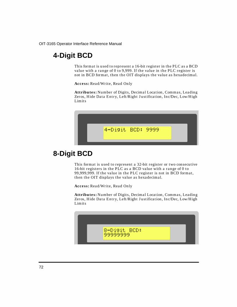
72
OIT-3165 Operator Interface Reference Manual
4-Digit BCD This format is used to represent a 16-bit register in the PLC as a BCD value with a range of 0 to 9,999. If the value in the PLC register is not in BCD format, then the OIT displays the value as hexadecimal.
Access: Read/Write, Read Only
Attributes: Number of Digits, Decimal Location, Commas, Leading Zeros, Hide Data Entry, Left/Right Justification, Inc/Dec, Low/High Limits
8-Digit BCD This format is used to represent a 32-bit register or two consecutive 16-bit registers in the PLC as a BCD value with a range of 0 to 99,999,999. If the value in the PLC register is not in BCD format, then the OIT displays the value as hexadecimal.
Access: Read/Write, Read Only
Attributes: Number of Digits, Decimal Location, Commas, Leading Zeros, Hide Data Entry, Left/Right Justification, Inc/Dec, Low/High Limits
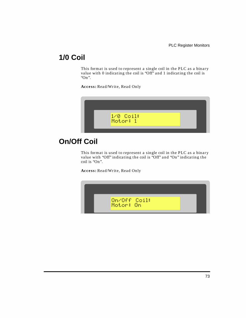
73
PLC Register Monitors
1/0 Coil This format is used to represent a single coil in the PLC as a binary value with 0 indicating the coil is “Off” and 1 indicating the coil is “On”.
Access: Read/Write, Read Only
On/Off Coil This format is used to represent a single coil in the PLC as a binary value with “Off” indicating the coil is “Off” and “On” indicating the coil is “On”.
Access: Read/Write, Read Only
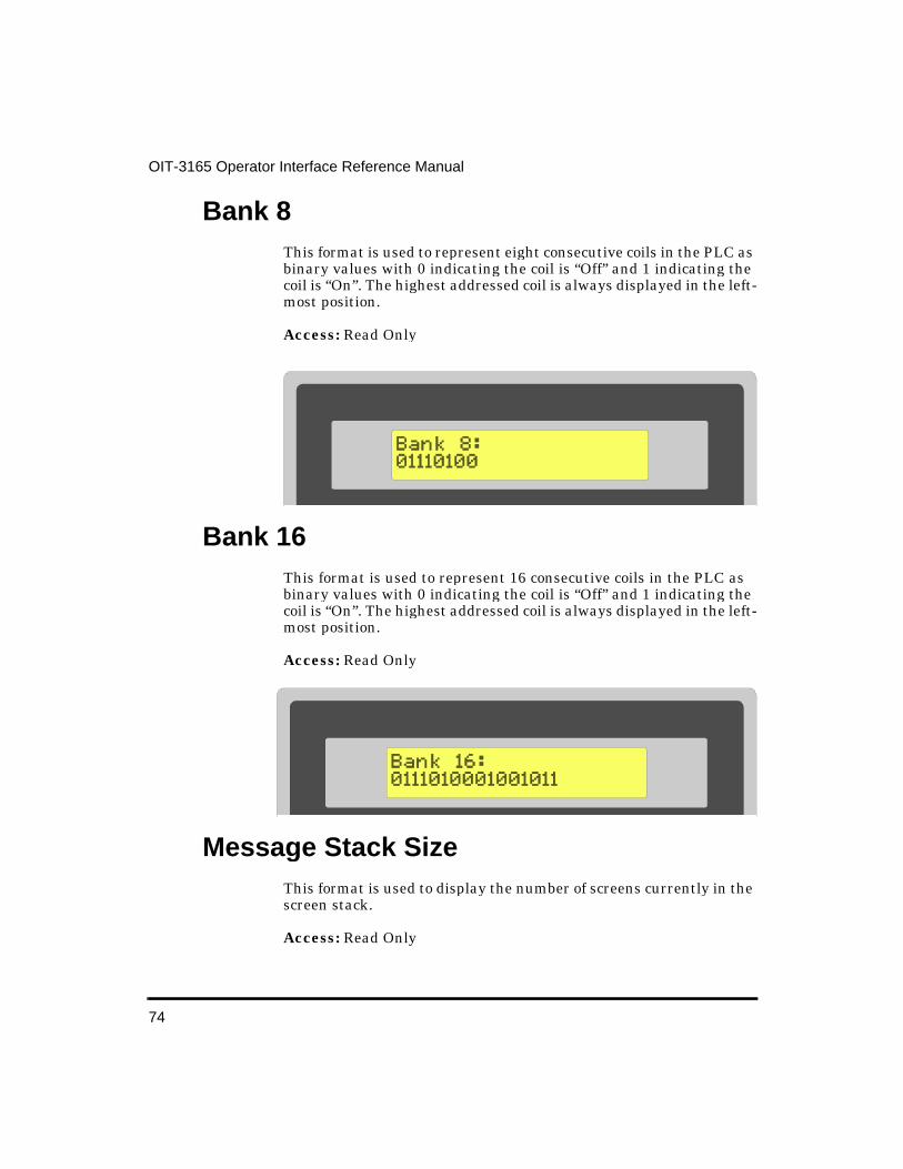
74
OIT-3165 Operator Interface Reference Manual
Bank 8 This format is used to represent eight consecutive coils in the PLC as binary values with 0 indicating the coil is “Off” and 1 indicating the coil is “On”. The highest addressed coil is always displayed in the left-most position.
Access: Read Only
Bank 16 This format is used to represent 16 consecutive coils in the PLC as binary values with 0 indicating the coil is “Off” and 1 indicating the coil is “On”. The highest addressed coil is always displayed in the left-most position.
Access: Read Only
Message Stack Size This format is used to display the number of screens currently in the screen stack.
Access: Read Only

75
PLC Register Monitors
Alarm Stack Size This format is used to display the number of alarms currently in the alarm stack.
Access: Read Only
ASCII Char This format is used to represent a 16-bit register in the PLC as a corresponding ASCII character. If the Number of Digits in the OITware-200 Register Monitor Editor dialog box is set to 2, the OIT reads the 16-bit register as two 8-bit ASCII characters and displays them. If the Number of Digits in the OITware-200 Register Monitor Editor dialog box is set to 1, the OIT reads the lowest eight bits of the 16-bit register and displays one ASCII character. If the data in the PLC register does not correspond to a displayable ASCII character(s), the OIT continues to show the last displayable ASCII character(s), or if there never was one, a space.
Access: Read Only
Attributes: Number of Digits
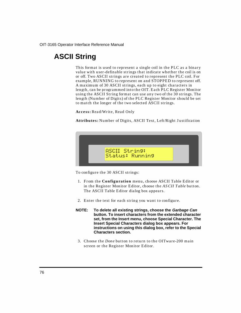
76
OIT-3165 Operator Interface Reference Manual
ASCII Strin g This format is used to represent a single coil in the PLC as a binary value with user-definable strings that indicate whether the coil is on or off. Two ASCII strings are created to represent the PLC coil. For example, RUNNING to represent on and STOPPED to represent off. A maximum of 30 ASCII strings, each up to eight characters in length, can be programmed into the OIT. Each PLC Register Monitor using the ASCII String format can use any two of the 30 strings. The length (Number of Digits) of the PLC Register Monitor should be set to match the longer of the two selected ASCII strings.
Access: Read/Write, Read Only
Attributes: Number of Digits, ASCII Text, Left/Right Justification
To configure the 30 ASCII strings:
1. From the Configuration menu, choose ASCII Table Editor or in the Register Monitor Editor, choose the ASCII Table button. The ASCII Table Editor dialog box appears.
2. Enter the text for each string you want to configure.
NOTE: To delete all existing strings, choose the Garbage Can button. To insert characters from the extended character set, from the Insert menu, choose Special Character. The Insert Special Characters dialog box appears. For instructions on using this dialog box, refer to the Special Characters section.
3. Choose the Done button to return to the OITware-200 main screen or the Register Monitor Editor.
77
PLC Register Monitors
PLC Register Monitor Attributes
Number of Di gits This attribute allows you to configure the number of character positions that the PLC Register Monitor occupies in the screen. If the data read from the PLC register requires more space than has been allocated, the overload character “#” appears in each character position of the PLC Register Monitor until a number within range is read.
Some of the other attributes (such as Decimal Location and Commas) increase the number of character positions that the PLC Register Monitor occupies in the screen.
To configure the Number of Digits in a PLC Register Monitor:
1. In the Register Monitor Editor dialog box, in the Attributes group box, in the Number of Digits scroll box, select the required length.
Decimal Location This attribute allows you to configure the location of the decimal point in the PLC Register Monitor. The decimal point is placed the specified number of characters from the right (for example: 0 = 12345, 1=1234.5, 2=123.45, etc.).
NOTE: When the Decimal Location is set to 1 or higher, the field width of the PLC Register Monitor is increased by one to include space for the decimal point.
To configure the Decimal Location in a PLC Register Monitor:
1. In the Register Monitor Editor dialog box, in the Attributes group box, in the “Decimal Location” scroll box, select the number of characters from the right to place the decimal point.

78
OIT-3165 Operator Interface Reference Manual
Commas This attribute adds commas every three characters to the PLC Register Monitor (for example: 1,234,567 would display instead of 1234567).
NOTE: When Commas is enabled, the field width of the PLC Register Monitor is increased by one for every three numbers in the Number of Digits attribute.
To enable Commas in a PLC Register Monitor:
1. In the Register Monitor Editor dialog box, in the Special Effects group box, select the “Commas” check box.
Linear Scalin g Linear Scaling is the term used to describe the process of converting one unit of measure to another, usually from a machine format to an operator-readable format, so the OIT operator has the data presented in readily understandable terms. A common application involves converting analog or digital data into degrees, speed, voltage, or temperature. If linear scaling is used on a read/write register monitor, the OIT operator can modify the data in the operator-readable format and it will be converted back into the machine format before being sent to the PLC register. Linear Scaling is available with the Signed, Decimal, and Long formats.
The linear scaling conversion is accomplished using the simple equation Y=MX+B, where “X” is the raw data read from the PLC, “Y” is the data presented to the OIT operator after the conversion, “M” is used to convert the scale of one unit of measure to another unit of measure, and “B” is the offset variable used for alignment.
For example, if an 8-bit A/D converter (255 steps) is used to measure voltage ranging from 0 to 15 volts, the raw data needs to be reduced so that a value of 255 A/D units equals 15 volts. The OIT needs to multiple the raw data by 1/17 (255/15=17) to properly convert the data into volts. Since the A/D value of 0 correctly represents 0 volts, the variable B is not used. The equation for this example would be Y = (1/17)X + 0.
Another example, suppose an 8-bit A/D converter (255 steps) is used to measure voltage ranging from 5 to 20 volts. Now we need to do two
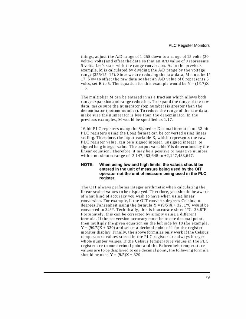
79
PLC Register Monitors
things, adjust the A/D range of 1-255 down to a range of 15 volts (20 volts-5 volts) and offset the data so that an A/D value of 0 represents 5 volts. Let’s start with the range conversion. As in the previous example, M is calculated by dividing the A/D range by the voltage range (255/15=17). Since we are reducing the raw data, M must be 1/17. Now to offset the raw data so that an A/D value of 0 represents 5 volts, set B to 5. The equation for this example would be Y = (1/17)X + 5.
The multiplier M can be entered in as a fraction which allows both range expansion and range reduction. To expand the range of the raw data, make sure the numerator (top number) is greater than the denominator (bottom number). To reduce the range of the raw data, make sure the numerator is less than the denominator. In the previous examples, M would be specified as 1/17.
16-bit PLC registers using the Signed or Decimal formats and 32-bit PLC registers using the Long format can be converted using linear scaling. Therefore, the input variable X, which represents the raw PLC register value, can be a signed integer, unsigned integer, or signed long integer value. The output variable Y is determined by the linear equation. Therefore, it may be a positive or negative number with a maximum range of -2,147,483,648 to +2,147,483,647.
NOTE: When using low and high limits, the values should be entered in the unit of measure being used by the OIT operator not the unit of measure being used in the PLC register.
The OIT always performs integer arithmetic when calculating the linear scaled values to be displayed. Therefore, you should be aware of what kind of accuracy you wish to have when using linear conversion. For example, if the OIT converts degrees Celsius to degrees Fahrenheit using the formula Y = (9/5)X + 32, 1°C would be converted to 34°F. Technically, this is inaccurate since 1°C=33.8°F. Fortunately, this can be corrected by simply using a different formula. If the conversion accuracy must be to one decimal point, then multiply the given equation on the left side by 10 (for example, Y = (90/5)X + 320) and select a decimal point of 1 for the register monitor display. Finally, the above formulas only work if the Celsius temperature values stored in the PLC register are always integer whole number values. If the Celsius temperature values in the PLC register are to one decimal point and the Fahrenheit temperature values are to be displayed to one decimal point, the following formula should be used Y = (9/5)X + 320.
80
OIT-3165 Operator Interface Reference Manual
To configure linear scaling in a PLC register monitor:
1. In the Register Monitor Editor dialog box, in the Special Effects group box, select the “Linear Scaling” check box. The Linear Scaling Parameters group box activates.
2. In the Linear Scaling Parameters group box, enter the M1, M2, and B values for your conversion formula or choose the Preset Lists button to select a preset formula from the Linear Scaling Presets List.

81
PLC Register Monitors
3. If this is a read/write register monitor, you can enter low and high limits to stop the OIT operator from entering invalid values.
NOTE: When using low and high limits, the values should be entered in the unit of measure being used by the OIT operator not the unit of measure being used in the PLC register.
82
OIT-3165 Operator Interface Reference Manual
Leadin g Zeros This attribute adds leading zeros to the PLC Register Monitor when the Decimal, 4-Digit BCD, or 8-Digit BCD format is used and the data read from the PLC register is shorter than the number specified in the Number of Digits attribute (for example: 0024 would display instead of 24 in 4-Digit BCD format).
To enable Leading Zeros in a PLC Register Monitor:
1. In the Register Monitor Editor dialog box, in the Special Effects group box, select the “Leading Zeros” check box.
Hide Data Entry This attribute displays asterisks in the PLC Register Monitor instead of the data read from the PLC register or typed by the OIT operator. This allows the system programmer to configure a process with restricted access. For example, a PLC register is configured in the PLC ladder logic program so that whenever the data in the PLC

83
PLC Register Monitors
register is equal to a specific number, the PLC starts a control process. Then a PLC Register Monitor is configured for that PLC register with the Hide Data Entry attribute enabled. Now the control process can only be started by an OIT operator who knows the correct access number. And data entry is secured since only asterisks are shown.
To enable Hide Data Entry in a PLC Register Monitor:
1. In the Register Monitor Editor dialog box, in the Special Effects group box, select the “Hide Data Entry” check box.
ASCII Text This attribute is used to configure the two ASCII strings used to represent the state of the specified PLC coil using ASCII String format. For information on configuring the 30 user-definable ASCII strings, refer to the ASCII String section.
To specify the two ASCII Strings in an ASCII String format PLC Register Monitor:
1. In the Register Monitor Editor dialog box, in the ASCII Text group box, select the “ASCII String” number (1 to 30) for the 0 and 1 PLC coil states.
NOTE: If you need to see the user-defined ASCII strings, choose the ASCII Table button. The ASCII Table Editor dialog box appears.
Left/Ri ght Justification This attribute displays the contents of the PLC Register Monitor with either left or right justification. Justification is the term used to describe placing all of the characters against the right or left margin regardless of the actual number of characters displayed.
To specify left or right justification in a PLC Register Monitor:
1. In the Register Monitor Editor dialog box, in the Justification group box, select the “Left” or “Right” radio button.
84
OIT-3165 Operator Interface Reference Manual
Inc/Dec This attribute allows you to enable the DELTA+ and DELTA- keys for use with the PLC Register Monitor and to configure the preset increment used by the DELTA+ and DELTA- keys to “jog” or adjust the value in the PLC Register Monitor.
To enable the DELTA+ and DELTA- keys in a PLC Register Monitor:
1. In the Register Monitor Editor dialog box, in the Inc/Dec group box, select the Enable check box and then select the preset increment to use.
Low/Hi gh Limits This attribute allows you to configure the Low and High Limits used to keep the OIT operator from entering an out-of-range value into the PLC Register Monitor. If the value entered by the OIT operator is lower than the Low Limit or higher than the High Limit an out-of-range warning is displayed. An option can be set in the OIT General Settings that allows the OIT to display the Low or High Limit with the out-of-range warning.
To configure the Low and High Limits in a PLC Register Monitor:
1. In the Register Monitor Editor dialog box, in the Limits group box, select the appropriate numbers for the “Low” and “High” limits.
To enable the low and high limits display with the out-of-range warning:
1. In the OITware-200 main screen, from the Configuration menu, choose General Settings. The OIT General Settings dialog box appears.
2. In the Options group box, select the “Show High” and “Low Limits” with “Out-Of-Range Warning” check box.
3. Choose the Done button to return to the OITware-200 main screen.
85
PLC Register Monitors
Set Points Set Points may be used for a variety of things including system warnings or alarms, multi-point warnings or alarms, restarting a recipe after a given number of units have been batch processed, or providing the OIT operator with a choice of actions when a trip point has been exceeded. Each OIT can have up to 16 set points active simultaneously. The system programmer provides the following information about each:
• PLC register address to monitor (known as set point address)
• format of PLC register (signed, decimal, 4-digit BCD, 8-digit BCD or long)
• low limit
• high limit
• screen number to display upon low limit violation
• screen number to display upon high limit violation
The set point addresses are monitored continuously by the OIT. The OIT polls one of the set point addresses every second. Therefore, having 16 set points means each set point is polled every 16 seconds.
If the OIT determines that the current value in the set point address is below the low limit or above the high limit, then the appropriate screen is displayed on the OIT. The screen displayed can be an alarm, message, recipe, or menu.
Once an out-of-range condition has occurred, the set point screens cannot be activated again until the set point address value comes back into range. For example, suppose a set point has been configured to monitor PLC address ADD1. The set point is configured to display Screen #1 if ADD1 falls below -100 and Screen #2 if ADD1 rises above 100. The PLC address starts with a value of 0 (in range). Then ADD1 falls to -200 (low limit range exceeded) causing the OIT to display Screen #1. If the next value of ADD1 is 200 (high limit range exceeded) the OIT will not display Screen #2, because ADD1 did not go back into range (-100 to 100) after the low limit range was exceeded. However, if ADD1 had changed from -200 to 10 to 200, Screen #2 would have been displayed.

86
OIT-3165 Operator Interface Reference Manual
NOTE: Depending on the poll rate (number of set points), data may change many times before being detected by the OIT.
In addition to the possible delay based on the poll rate, the response time of low limit or high limit violations can vary depending on the communications speed and the amount of data overhead of each PLC protocol. Therefore, if the set points are used as alarms, they should be treated as auxiliary alarms and placed at priorities 3 and 4 while PLC generated alarms are placed at priorities 1 and 2.
NOTE: Under no circumstances should set points be used to monitor safety critical processes or limits!
To configure a set point:
1. From the Configuration menu, choose Setpoints Editor. The Set Points Editor dialog box appears.
2. In the PLC Interface group box, select the “PLC Register” and “Address” to be monitored.
3. In the PLC Interface group box, select the “Format” used in the selected PLC register.

87
PLC Register Monitors
4. In the Low Set Point group box, enter the “Low Limit” (trip point).
5. In the Low Set Point group box, enter the “Screen” to display upon low limit violation.
NOTE: Choose the View button to view the selected screen.
6. In the High Set Point group box, enter the “High Limit” (trip point).
7. In the High Set Point group box, enter the “Screen” to display upon high limit violation.
8. Choose the Add To Set Points List button to create the set point. The new set point appears in the Set Points List group box.
NOTE: The Set Points List group box is used to view or remove existing set points.

89
Displa ying StoredScreens
This chapter describes the methods that can be used to display stored screens on the OIT.
Startup Screen One message, recipe, or menu screen can be designated as the startup screen. The startup screen automatically appears whenever the OIT is powered-up. For instructions on designating the startup screen, refer to the Startup Screen section.
PLC Screen Request The PLC can request that the OIT display any stored screen using the Message Request Register (MRR). The MRR is a register in the PLC that is continuously monitored by the OIT. When a new value is read from the MRR, the corresponding screen is immediately displayed on the OIT with the following exceptions:
• When the screen stack is in Stacked mode, only alarm screens are immediately displayed, all other screens are stored in the stack until the OIT operator presses the NEXT MESSAGE key.
• The only screen request that can write over the top of an unacknowledged alarm screen is a higher priority alarm screen. Non-alarm screen requests received in this situation are ignored if the screen stack is in Standard mode and saved in the stack if the screen stack is in Stacked mode. Lower priority alarm screens received in this situation are stored in the alarm stack.
OIT-3165 Operator In-

90
OIT-3165 Operator Interface Reference Manual
Once the OIT displays the screen requested in the MRR, the OIT must see a change in the number in the MRR in order to display another screen request from the PLC. For example, the PLC requests that Screen #5 be displayed. The OIT operator then presses Function Key #1 which displays Screen #30. The number 5 is still in the MRR, but since no change has occurred it is ignored by the OIT. The PLC can get the OIT to display the same screen twice without an intervening PLC screen request, by simply putting the number 0 into the MRR between the two identical screen requests. The OIT does not perform any action as a result of seeing the number 0 in the MRR, but it does note that a change occurred.
NOTE: There is a feature that allows the OIT to clear the MRR after each PLC screen request.
Two types of MRRs are available: Value and Bit Position.
MRR–Value When a value MRR is used, the PLC requests screens by placing decimal or BCD numbers into the MRR.
MRR–Bit Position When a bit position MRR is used, the PLC requests a screen by setting a bit instead of writing a number. Each bit in the specified MRR address corresponds to one of 16 stored screens in the OIT. To access more than 16 of the OIT’s 500 stored screens, you must configure multiple bit position MRRs. Up to 32 can be configured.
NOTE: Only one MRR is polled every 200 milliseconds. Therefore, if two MRRs are configured, it takes 400 milliseconds to poll them.
To determine which stored screen to display, the OIT examines each bit in the polled MRR and then displays the stored screen that corresponds to the first set bit.
Confi gurin g the MRR without Enhanced Features
1. From the Configuration menu, choose Message Control Settings. The OIT Message Control Settings dialog box appears.

91
Displaying Stored Screens
2. In the Message Request Register group box, select the “Enable” check box.
3. In the Message Request Register group box, in the scroll box, specify the PLC address for the MRR.
4. In the MRR/CMR Data Format group box, specify the data format for the MRR and CMR.
5. Choose the Done button to return to the OITware-200 main screen.
Confi gurin g the MRR with Enhanced Features
To use a bit position MRR, use multiple MRRs, clear the MRR after each PLC screen request, or leave the MRR(s) in their existing state on OIT power-up, requires the enhanced features.
1. From the Configuration menu, choose Message Control Settings. The OIT Message Control Settings dialog box appears.
2. In the Message Request Register group box, select the “Enable” check box.

92
OIT-3165 Operator Interface Reference Manual
3. In the Message Request Register group box, select the “Use Enhanced Features” check box. The MRR Editor button activates.
93
Displaying Stored Screens
4. Choose the MRR Editor button. The Message Request Register Editor dialog box appears.
5. In the Address For Message Request Register #1 group box, in the scroll box, specify the PLC address for this MRR.
6. In the Show Screen Based On group box, select the “MRR Value” or “MRR Bit Position” radio button.
7. If creating a bit position MRR, in the Show Screen Based On group box, in the scroll box, select the starting screen number for this MRR’s sixteen screen range.
8. If creating a value MRR, in the Options group box, specify the data format for this MRR.
9. If you want the OIT to clear the MRR after each PLC screen request, in the Options group box, select the “Clear Register/Bit After Receiving Screen Request” check box.
10. Choose the Create New MRR Entry button. This MRR is added.
11. Repeat steps 5 through 10 for each additional MRR to be created.
94
OIT-3165 Operator Interface Reference Manual
12. If you want the OIT to set all MRRs to 0 whenever the OIT powers-up, in the General Options group box, select the “Clear All Message Request Register On OIT Initialization” check box.
13. Choose the Done button to return to the OIT Message Control Settings dialog box.
14. Choose the Done button to return to the OITware-200 main screen.
Function Keys Every global and screen-dependent function key on the OIT can be programmed to display a stored screen. Whenever the function key is pressed, the corresponding screen is immediately displayed, unless an alarm is active or a security password is being used. For more information on configuring function keys, refer to the Key Types section.
NOTE: When a function key displays an Alarm or Help screen, the screen is treated like a simple message screen.
Menu Selection Menu screens allow the OIT operator to branch off to other message, recipe or menu screens by pressing the associated numeric key. Each menu screen can branch to as many as nine other screens using the 1 through 9 keys. For more information on configuring menu screens, refer to the Menu Screens section.
95
Displaying Stored Screens
Message or Menu Chain — Pa ge Up and Page Down Keys
Message or menu screens can be chained together to form multiple screen messages or menus. This allows a group of screens to be displayed with only one PLC screen request, or one function key press, or one menu selection. For more information on configuring message/menu screen chains, refer to the Screen Chain section.
The PAGE DOWN and PAGE UP keys are used by the OIT operator to view the screens in a chain. PAGE DOWN is used to view the next screen in a chain; PAGE UP is used to view the prior screen.
Three special symbols are used in the screens to indicate to the OIT operator which screen in the chain is being displayed. The “->” symbol is used in the first screen, the “<->” symbol is used in the middle screens, and the “<-” symbol is used in the last screen.
Screen Stack — Last Ms g and Next Msg Keys
The OIT has a screen stack that temporarily stores up to 10 screens requested by either the PLC or OIT. The following are not stored in the screen stack:
• alarm screens requested by the PLC • help screens requested by the HELP key • any screen requested by a function key that uses a password • startup screen • screen saver
The LAST MESSAGE and NEXT MESSAGE keys are used to view the messages in the screen stack. There are two available screen stack operating modes: Standard and Stacked.
Standard Mode
In Standard mode, screens requested by the PLC or OIT enter the stack only after being displayed. When an alarm screen is displayed,
96
OIT-3165 Operator Interface Reference Manual
all non-alarm screen requests are ignored; they are not displayed or stored in the stack. When the stack contains 10 screens, adding another screen causes the oldest screen to fall out of the stack.
When the OIT operator presses the LAST MSG key, the most recent screen in the stack is redisplayed. Pressing the LAST MSG key again, redisplays the next oldest screen in the stack. When the OIT operator presses the NEXT MSG key:
• If a screen from the stack is currently being redisplayed, the next newest screen in the stack is redisplayed.
• Otherwise, nothing happens.
If the stack contains a screen that is part of a chain, the OIT operator can use the PAGE DOWN and PAGE UP keys to view the other screens in the chain.
To configure the screen stack for Standard mode:
1. From the Configuration menu, choose Message Control Settings. The OIT Message Control Settings dialog box appears.
2. In the Message Request Register group box, make sure the “Enable Message Stack” group box is not selected.
3. Choose the Done button to return to the OITware-200 main screen.
Stacked Mode
In Stacked mode, screens requested by the PLC are sent directly to the stack. The OIT operator must press the NEXT MSG key to display them. This ensures that the OIT operator has enough time to read each screen. However, screens requested by the OIT (except timer event screens) still operate the same as in Standard mode.
If an alarm screen is displayed when the PLC requests a non-alarm screen, the non-alarm screen is sent directly to the stack, where it can be displayed by the OIT operator after the alarm is acknowledged. In this situation, non-alarm screens requested by the OIT (except timer event screens) are still ignored; they are not displayed or stored in the stack.
97
Displaying Stored Screens
The stack only holds 10 screens; this includes historical screens and screens waiting to be displayed. Adding an 11th screen causes the oldest historical screen to fall out of the stack. If there are no historical screens, then the oldest screen waiting to be displayed falls out of the stack.
When the OIT operator presses the LAST MSG key, the most recent historical screen in the stack is redisplayed. Pressing the LAST MSG key again, redisplays the next oldest historical screen in the stack. When the OIT operator presses the NEXT MSG key:
• If there are any screens waiting to be displayed, the oldest one is displayed.
• If there are no screens waiting to be displayed and a historical screen is currently being redisplayed, the next newest historical screen in the stack is redisplayed.
If the stack contains a screen that is part of a chain, the OIT operator can use the PAGE DOWN and PAGE UP keys to view the other screens in the chain.
There are two ways to inform the OIT operator when new screens are in the stack:
• Embedding the Message Stack Size register monitor in each screen. For more information on using this register monitor format, refer to the PLC Register Monitors section.
To configure the screen stack for Stacked mode:
1. From the Configuration menu, choose Message Control Settings. The OIT Message Control Settings dialog box appears.
2. In the Message Request Register group box, select the “Enable Message Stack” group box.
3. Choose the Done button to return to the OITware-200 main screen.
98
OIT-3165 Operator Interface Reference Manual
Help Key Each message, recipe or menu screen can have one help screen assigned that is displayed whenever the OIT operator presses the HELP key. The help screen remains on the display as long as the HELP key is pressed. When the HELP key is released, the prior screen reappears. If the HELP key is pressed for a screen that does not have an assigned help screen, an error message is displayed. For more information on configuring a help screen, refer to the Help Screens section.
Screen Saver The screen saver is a single line of up to 128 characters that can be configured to display whenever there has been no keyboard activity or PLC screen request for a predefined length of time. Although originally designed to prevent phosphor burn on vacuum fluorescent displays, the screen saver is an option available for all OIT Family Operator Interface Terminals. The single line of text scrolls across the top line of the display at a rate of two characters per second until the OIT operator presses a key or the PLC requests a screen.
To enable the screen saver:
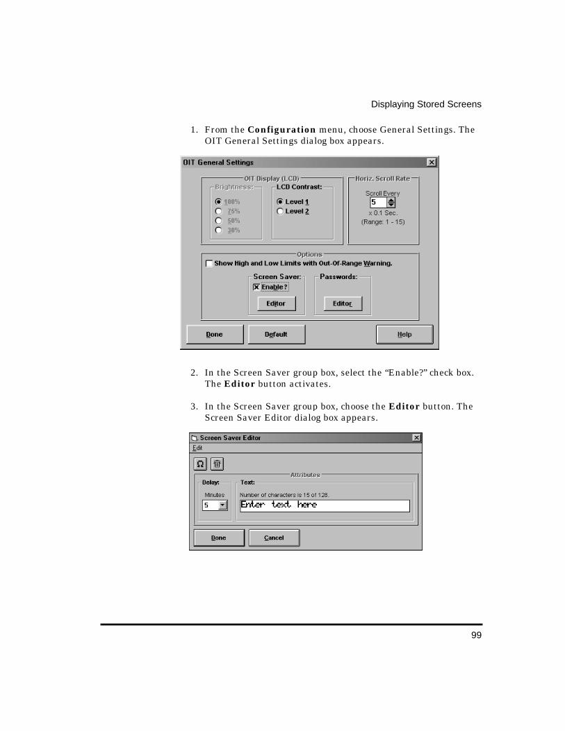
99
Displaying Stored Screens
1. From the Configuration menu, choose General Settings. The OIT General Settings dialog box appears.
2. In the Screen Saver group box, select the “Enable?” check box. The Editor button activates.
3. In the Screen Saver group box, choose the Editor button. The Screen Saver Editor dialog box appears.

100
OIT-3165 Operator Interface Reference Manual
4. In the Delay group box, in the “Minutes” drop down list box, select the number of minutes the OIT should wait when inactive before starting the screen saver. The available options include every 5 minutes from 5 to 60.
5. In the Text group box, type the text to display when the screen saver is active.
NOTE: To delete the string of text from the Text group box, choose the Garbage Can button. To insert characters from the extended character set, from the Edit menu, choose Insert Special Character. The Insert Special Characters dialog box appears. For instruction on using this dialog box, refer to the Special Characters section in CHAPTER 3: Stored Screens.
6. Choose the Done button, to return to the OIT General Settings dialog box.
7. Choose the Done button, to return to the OITware-200 main screen.
Set Points Each OIT can have up to 16 set points. For each set point, the OIT monitors the value in a PLC register. When that value exceeds the specified low or high limit, the specified stored screen is displayed. For more information, refer to the Set Points section in the PLC Register Monitors sectiion.

101
Key Types
Function Ke ys Each OIT has many function keys which can be programmed to display screens or turn on/off PLC coils. The following modes of operation are available for each function key.
Passwords Each function key configured as Screen Display can have one of four password levels assigned to it. This provides the ability to restrict access to certain messages. Each password must be four digits long and contain only numbers (the default for each password is 0000). The four password levels from highest to lowest level of access are Level 1, Level 2, Level 3 and Level 4. Therefore, if a function key is assigned Level 3, the Level 1, Level 2, and Level 3 passwords all allow the OIT operator to view the screen.
Function Key Mode Operation
Disabled No operation.
Push On/Off Emulates on/off switch. Sets assigned PLC coil when pressed; clears PLC coil when pressed again.
Latched Sets assigned PLC coil when pressed. PLC must clear coil.
Momentary Emulates momentary switch. Sets assigned PLC coil when pressed; clears PLC coil when released.
Screen Display When pressed, displays assigned stored screen unless password protection is enabled or an alarm screen is currently displayed. If password protection is enabled, the OIT operator is prompted for a password and the screen is only displayed if the password is entered correctly. If an alarm screen is displayed, the function key is ignored.
OIT-3165 Operator In-
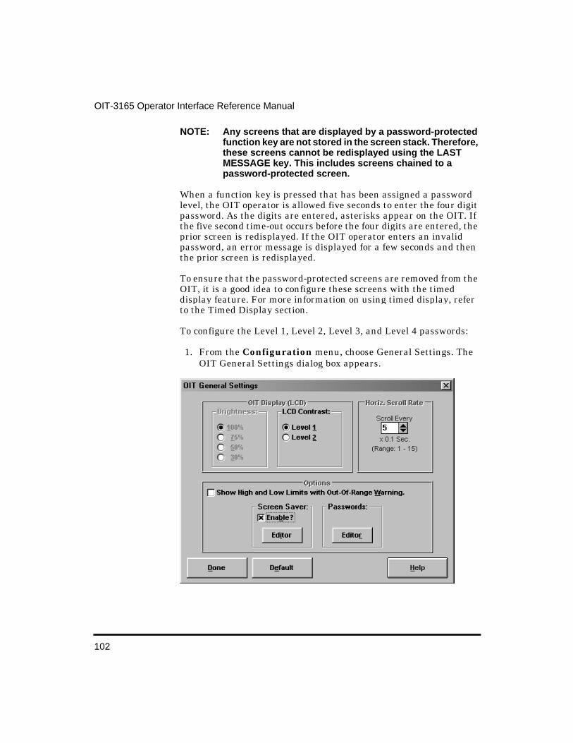
102
OIT-3165 Operator Interface Reference Manual
NOTE: Any screens that are displayed by a password-protected function key are not stored in the screen stack. Therefore, these screens cannot be redisplayed using the LAST MESSAGE key. This includes screens chained to a password-protected screen.
When a function key is pressed that has been assigned a password level, the OIT operator is allowed five seconds to enter the four digit password. As the digits are entered, asterisks appear on the OIT. If the five second time-out occurs before the four digits are entered, the prior screen is redisplayed. If the OIT operator enters an invalid password, an error message is displayed for a few seconds and then the prior screen is redisplayed.
To ensure that the password-protected screens are removed from the OIT, it is a good idea to configure these screens with the timed display feature. For more information on using timed display, refer to the Timed Display section.
To configure the Level 1, Level 2, Level 3, and Level 4 passwords:
1. From the Configuration menu, choose General Settings. The OIT General Settings dialog box appears.
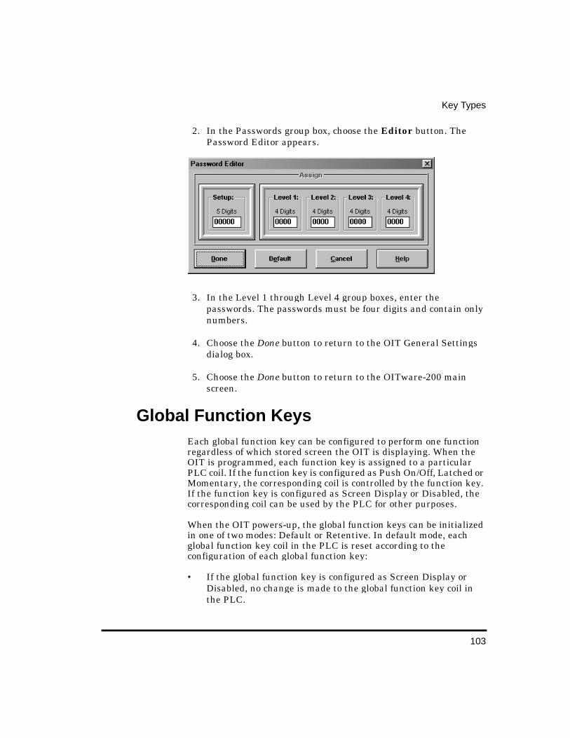
103
Key Types
2. In the Passwords group box, choose the Editor button. The Password Editor appears.
3. In the Level 1 through Level 4 group boxes, enter the passwords. The passwords must be four digits and contain only numbers.
4. Choose the Done button to return to the OIT General Settings dialog box.
5. Choose the Done button to return to the OITware-200 main screen.
Global Function Keys Each global function key can be configured to perform one function regardless of which stored screen the OIT is displaying. When the OIT is programmed, each function key is assigned to a particular PLC coil. If the function key is configured as Push On/Off, Latched or Momentary, the corresponding coil is controlled by the function key. If the function key is configured as Screen Display or Disabled, the corresponding coil can be used by the PLC for other purposes.
When the OIT powers-up, the global function keys can be initialized in one of two modes: Default or Retentive. In default mode, each global function key coil in the PLC is reset according to the configuration of each global function key:
• If the global function key is configured as Screen Display or Disabled, no change is made to the global function key coil in the PLC.
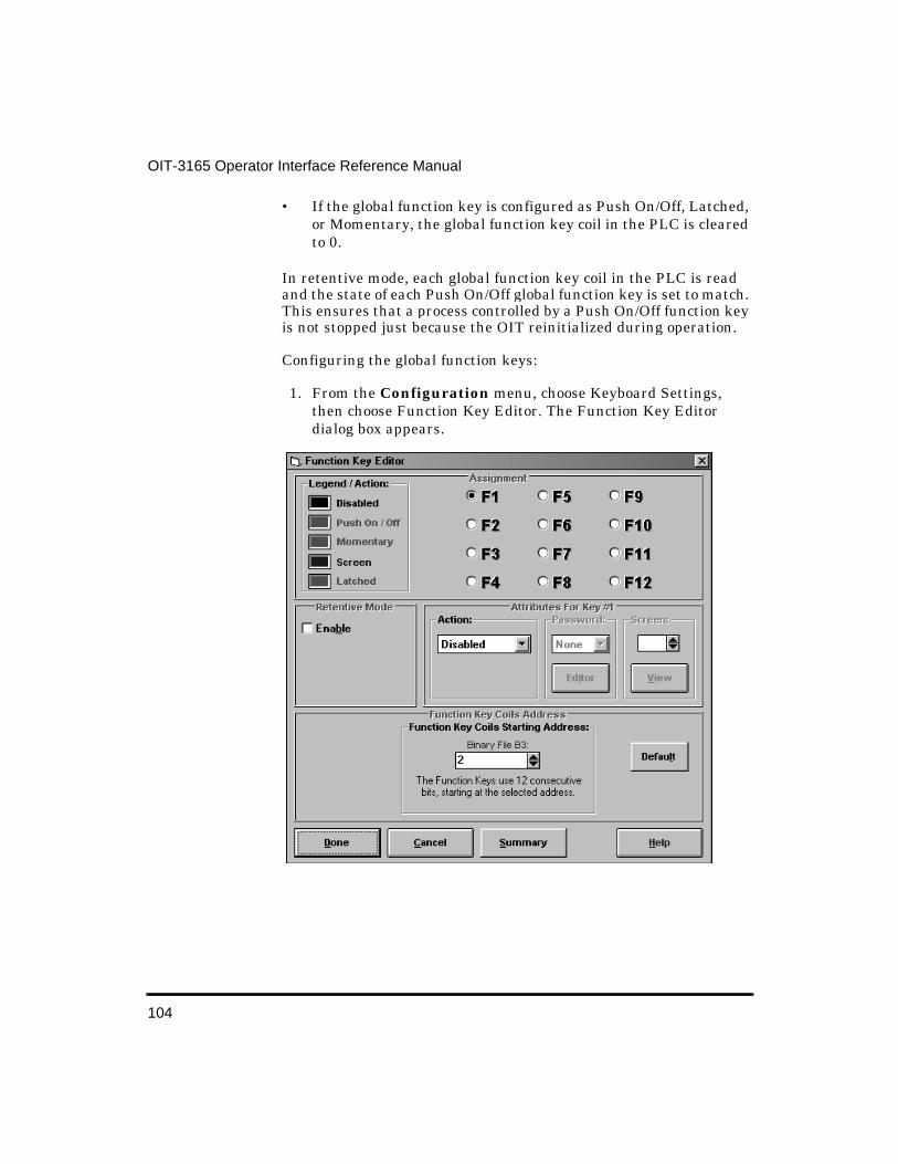
104
OIT-3165 Operator Interface Reference Manual
• If the global function key is configured as Push On/Off, Latched, or Momentary, the global function key coil in the PLC is cleared to 0.
In retentive mode, each global function key coil in the PLC is read and the state of each Push On/Off global function key is set to match. This ensures that a process controlled by a Push On/Off function key is not stopped just because the OIT reinitialized during operation.
Configuring the global function keys:
1. From the Configuration menu, choose Keyboard Settings, then choose Function Key Editor. The Function Key Editor dialog box appears.
105
Key Types
2. In the Function Key Coils Starting Address group box, select the starting PLC coil address to use for the global function key coils. The global function key coils are a consecutive block of coils, one for each global function key on your OIT, that start at the selected PLC address.
3. In the Retentive Mode group box, select the “Enable” check box if you want the global function key coils in the PLC to retain their last known state when the OIT reinitializes. For more information, refer to the OIT Initialization section.
4. In the Assignment group box, choose the radio button that corresponds to the global function key you want to configure.
5. In the Action group box, choose the action this global function key will perform.
6. If you selected Screen, in the “Screen” scroll box, select the stored screen number to display when this global function key is pressed.
7. If you selected Screen and want to use the password feature, in the “Password” drop down list box, select the appropriate password level. For more information on passwords, refer to the Passwords section.
8. Repeat steps 4 through 7 for each global function key.
9. Choose the Done button to return to the OITware-200 main screen.
Screen Dependent Function Keys Each screen dependent function key can be configured to perform a different function in each of the OIT’s stored screens. In addition, each screen dependent function key can be configured with a global function.
When you start a new project in OITware-200, each screen dependent function key’s global function is set as disabled. If you want a screen dependent function key to perform the same function in many or all of the OIT’s stored screens, you should configure its global function for that purpose.
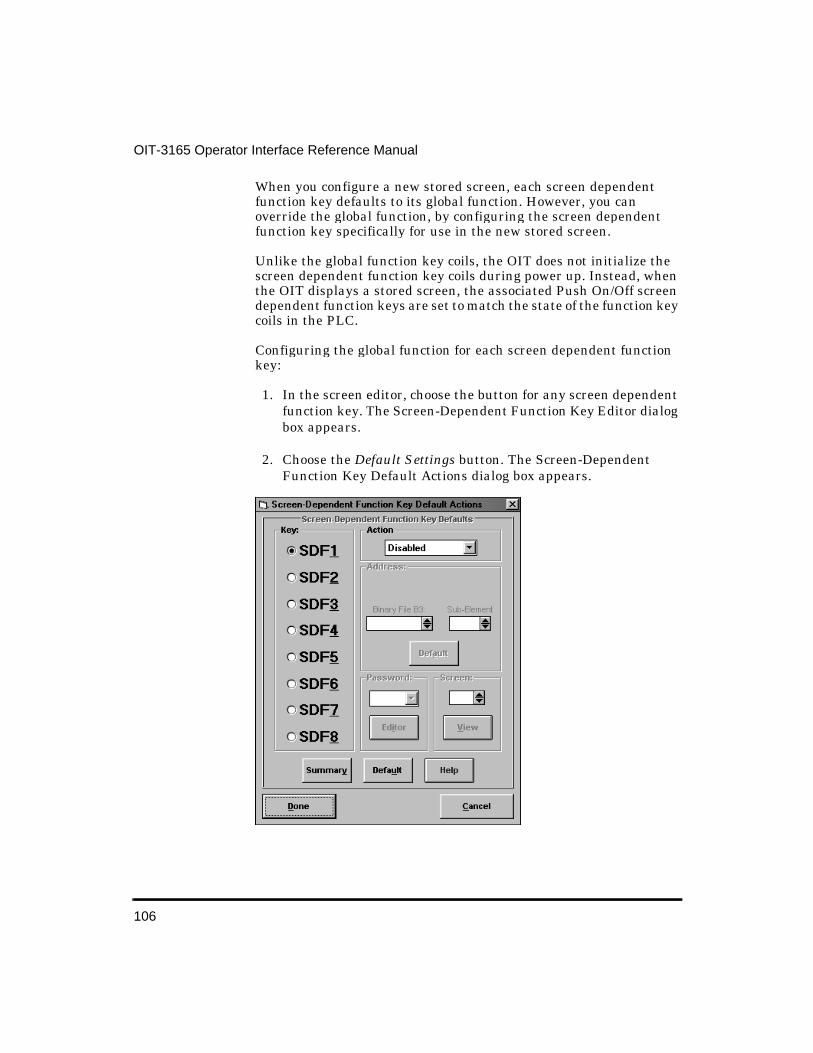
106
OIT-3165 Operator Interface Reference Manual
When you configure a new stored screen, each screen dependent function key defaults to its global function. However, you can override the global function, by configuring the screen dependent function key specifically for use in the new stored screen.
Unlike the global function key coils, the OIT does not initialize the screen dependent function key coils during power up. Instead, when the OIT displays a stored screen, the associated Push On/Off screen dependent function keys are set to match the state of the function key coils in the PLC.
Configuring the global function for each screen dependent function key:
1. In the screen editor, choose the button for any screen dependent function key. The Screen-Dependent Function Key Editor dialog box appears.
2. Choose the Default Settings button. The Screen-Dependent Function Key Default Actions dialog box appears.
107
Key Types
3. In the Key group box, choose the option button for the screen dependent function key you want to configure.
4. In the “Action” drop down list box, choose the action you want this screen dependent function key to perform.
5. If you selected “Push On/Off”, “Momentary” or “Latched”, in the Address group box, select the PLC coil address to use for this screen dependent function key.
6. If you selected Screen, in the “Screen” scroll box, select the stored screen number to display when this screen dependent function key is pressed.
7. If you selected Screen and want to use the password feature, in the “Password” drop down list box, select the appropriate password level. For more information on passwords, refer to the Passwords section in this chapter.
8. Repeat steps 3 through 7 for each screen dependent function key.
9. Choose the Done button to return to the Screen-Dependent Function Key Editor dialog box.
10. Choose the Done button to return to the OITware-200 main screen.
Configuring a screen dependent function key for a specific stored screen:
1. In the screen editor, display the screen you want to configure the screen dependent function key for.
2. In the screen editor, choose the button for the screen dependent function key you want to configure. The Screen-Dependent Function Key Editor dialog box appears.
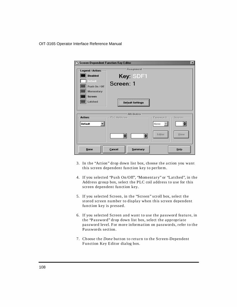
108
OIT-3165 Operator Interface Reference Manual
3. In the “Action” drop down list box, choose the action you want this screen dependent function key to perform.
4. If you selected “Push On/Off”, “Momentary” or “Latched”, in the Address group box, select the PLC coil address to use for this screen dependent function key.
5. If you selected Screen, in the “Screen” scroll box, select the stored screen number to display when this screen dependent function key is pressed.
6. If you selected Screen and want to use the password feature, in the “Password” drop down list box, select the appropriate password level. For more information on passwords, refer to the Passwords section.
7. Choose the Done button to return to the Screen-Dependent Function Key Editor dialog box.
109
Key Types
8. Choose the Done button to return to the OITware-200 main screen.
Control Keys Following is a description of how each control key operates. When configuring the OIT-3165, you should use the requirements paragraphs when deciding which keys to place on your user-defined keypad.
Alarm Acknowled ge The ALARM ACKNOWLEDGE key is used to acknowledge the alarm currently in progress and remove it from the alarm stack.
Requirements: If using alarm screens, the ALARM ACKNOWLEDGE key is required unless you use the PLC to clear the alarms. Using the PLC to clear alarms is not recommended, since there will be no way to know if the OIT operator saw the alarm.
Arrow The arrow keys are used to move the cursor from one read/write PLC register monitor to another. Each time one of the arrow keys is pressed, the cursor moves to the next closest read/write PLC register monitor in the direction of the pressed arrow key. When the cursor is located at one of the edges of the display, additional keypresses in the direction of the display edge cause the cursor to wrap around.
Requirements: If using read/write PLC register monitors, either the right arrow key or left arrow key is required. Additional arrow keys can reduce the keypresses required to access certain read/write PLC register monitors on the screen, but are not necessary.
Delta+ and Delta- The DELTA+ and DELTA- keys are used in read/write PLC register monitors that have been configured with a preset increment/decrement value. When the cursor is on a read/write PLC register monitor with a preset increment/decrement value, the DELTA+ key
110
OIT-3165 Operator Interface Reference Manual
increments the value in the PLC register monitor on the screen by the preset value and the DELTA- key decrements the value. These changes are immediately written to the PLC register. If pressing the DELTA+ or DELTA- key causes the value in the PLC register monitor to bump against the preset low or high limit, the key is ignored.
Requirements: If using preset increment/decrement values with a read/write PLC register monitor, the DELTA+ key is required to increment and the DELTA- key is required to decrement.
Help The HELP key is used to display an attached help screen from a message, recipe, or menu screen. The help screen is displayed as long as the HELP key is pressed. When released, the original message, recipe, or menu screen is redisplayed.
Requirements: If using help screens, the HELP key is required.
Last Messa ge and Next Messa ge The LAST MESSAGE and NEXT MESSAGE keys are used to display the screens in the screen stack.
Requirements: If using the screen stack in Stacked mode, the NEXT MESSAGE key is required to display new screens and the LAST MESSAGE and NEXT MESSAGE keys are required to redisplay screens from history. If using the screen stack in Standard mode, the LAST MESSAGE and NEXT MESSAGE keys are required to display screens from history.
Page Up and Pa ge Down The PAGE UP and PAGE DOWN keys are used to move through a group of chained screens.
Requirements: If using chained screens, the PAGE DOWN key is required to move forward through the chain. The PAGE UP key is used to move backwards through the chain and is optional. Linking the last screen in the chain to the first screen in the chain forms a loop and allows the OIT operator to display previous screens in the chain when only the PAGE DOWN key is available.

111
Key Types
Setup The SETUP key is used to place the OIT into setup mode during operation.
Toggle The TOGGLE key is used to perform two functions:
• In setup mode, pressing TOGGLE advances through the various selections for the current menu.
• When the cursor is on a binary read/write PLC register monitor, pressing TOGGLE changes between the two binary values. The change is immediately written to the PLC register.
Requirements: To make changes in setup mode or to change the value in a binary read/write PLC register monitor, the TOGGLE key is required.
Edit Keys
Clear The CLEAR key is used to perform three functions:
• If an alarm is active, pressing CLEAR turns off the buzzer.
• In setup mode, pressing CLEAR backs out of the menus and eventually exits setup mode without saving any changes.
• When the cursor is on a read/write PLC register monitor, pressing CLEAR activates data entry mode and clears the register monitor’s contents.
Requirements: The CLEAR key is not required when using alarms, since the ALARM ACKNOWLEDGE key also turns off the buzzer. The CLEAR key is not required in setup mode, since you do not have to back out of the menus. The CLEAR key is required to change the
112
OIT-3165 Operator Interface Reference Manual
value in a read/write PLC register monitor when using the numeric keys. However, you can configure read/write PLC register monitors with preset increment/decrement values and then use the DELTA+ and DELTA- keys to change the read/write PLC register monitor value instead of using the numeric, CLEAR and ENTER keys.
Enter The ENTER key is used to perform two functions:
• In setup mode, pressing ENTER accepts the current entry and advances to the next menu.
• When the cursor is on a read/write PLC register monitor, pressing ENTER accepts the data entered by the OIT operator and updates the PLC register.
Requirements: The ENTER key is required to use setup mode. The ENTER key is required to change the value in a read/write PLC register monitor when using the numeric keys. However, you can configure read/write PLC register monitors with preset increment/decrement values and then use the DELTA+ and DELTA- keys to change the read/write PLC register monitor value instead of using the numeric, CLEAR, and ENTER keys.
Numeric Keys
0 to 9
The 0 to 9 keys are used to enter passwords (setup, alarm, or function key) and to change values in read/write PLC register monitors.
Requirements: The 0 to 9 keys are required when using passwords. However, all passwords are optional. The 0 to 9 keys are not required to change the value in a read/write PLC register monitor. Instead you can configure read/write PLC register monitors with preset increment/decrement values and then use the DELTA+ and DELTA- keys to change the read/write PLC register monitor values.
113
Key Types
+/-
The +/- key changes the sign of the value in the current read/write PLC register monitor.
Requirements: The +/- key is not required unless the OIT operator needs to enter negative values into read/write PLC register monitors.
Delete
The DELETE key is used, when editing a read/write PLC register monitor, to perform a destructive backspace at the cursors current position in the screen.
Requirements: The DELETE key is not required if you have a CLEAR key, since the CLEAR key clears the entire entry and lets you start over.
Control, Edit and Numeric Key Coils Each of the OIT’s control, edit and numeric keys can be programmed to:
• Only perform normal OIT action • Only set/clear a PLC coil
NOTE: Pressing the key sets the coil; releasing the key clears the coil.
• Perform normal OIT action and set/clear a PLC coil • Do nothing (disabled)
When a new OITware-200 project is started, all of the control, edit and numeric keys default to OIT Action mode (they only perform their normal OIT action). If you want one or all of the keys to function in a different mode, you need to use the OIT Control Key Editor.
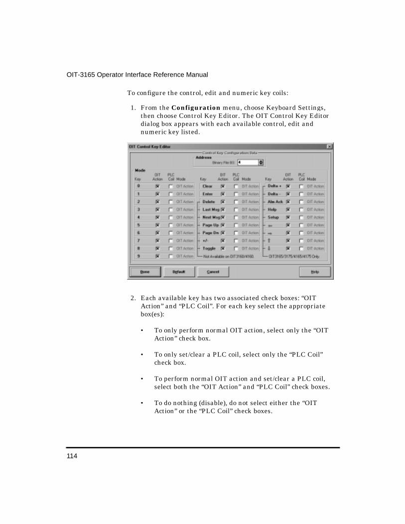
114
OIT-3165 Operator Interface Reference Manual
To configure the control, edit and numeric key coils:
1. From the Configuration menu, choose Keyboard Settings, then choose Control Key Editor. The OIT Control Key Editor dialog box appears with each available control, edit and numeric key listed.
2. Each available key has two associated check boxes: “OIT Action” and “PLC Coil”. For each key select the appropriate box(es):
• To only perform normal OIT action, select only the “OIT Action” check box.
• To only set/clear a PLC coil, select only the “PLC Coil” check box.
• To perform normal OIT action and set/clear a PLC coil, select both the “OIT Action” and “PLC Coil” check boxes.
• To do nothing (disable), do not select either the “OIT Action” or the “PLC Coil” check boxes.
115
Key Types
3. If you selected any “PLC Coil” check boxes, in the “Address” scroll box, set the starting PLC address for the key coils.
NOTE: This address represents the first bit in the Bit Memory area of the PLC to use for the control, edit and numeric key coils. Every available control, edit and numeric key is assigned a coil; even if the associated PLC Coil check box for the key was not selected. The first bit represents the 0 key, the second bit the 1 key, etc.
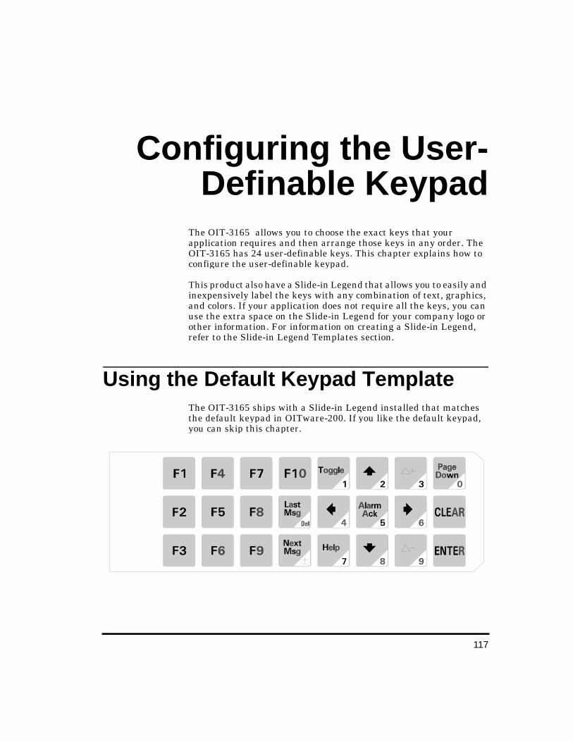
117
Confi gurin g the User-Definable Ke ypad
The OIT-3165 allows you to choose the exact keys that your application requires and then arrange those keys in any order. The OIT-3165 has 24 user-definable keys. This chapter explains how to configure the user-definable keypad.
This product also have a Slide-in Legend that allows you to easily and inexpensively label the keys with any combination of text, graphics, and colors. If your application does not require all the keys, you can use the extra space on the Slide-in Legend for your company logo or other information. For information on creating a Slide-in Legend, refer to the Slide-in Legend Templates section.
Usin g the Default Ke ypad Template The OIT-3165 ships with a Slide-in Legend installed that matches the default keypad in OITware-200. If you like the default keypad, you can skip this chapter.
OIT-3165 Operator In-
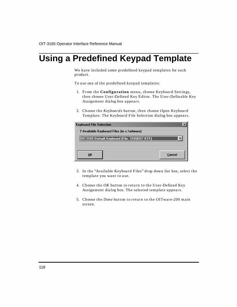
118
OIT-3165 Operator Interface Reference Manual
Usin g a Predefined Keypad Template We have included some predefined keypad templates for each product.
To use one of the predefined keypad templates:
1. From the Configuration menu, choose Keyboard Settings, then choose User-Defined Key Editor. The User-Definable Key Assignment dialog box appears.
2. Choose the Keyboards button, then choose Open Keyboard Template. The Keyboard File Selection dialog box appears.
3. In the “Available Keyboard Files” drop down list box, select the template you want to use.
4. Choose the OK button to return to the User-Defined Key Assignment dialog box. The selected template appears.
5. Choose the Done button to return to the OITware-200 main screen.
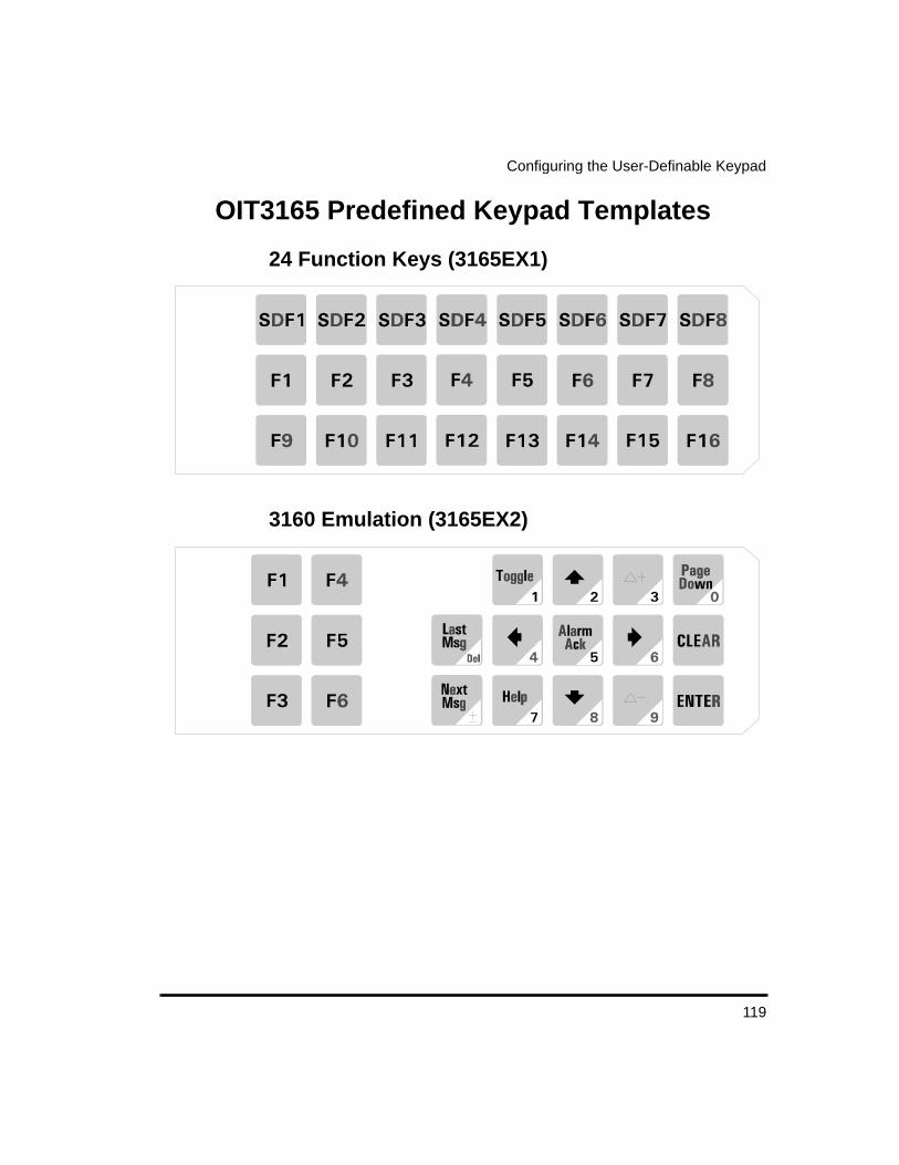
119
Configuring the User-Definable Keypad
OIT3165 Predefined Keypad Templates
24 Function Keys (3165EX1)
3160 Emulation (3165EX2)

120
OIT-3165 Operator Interface Reference Manual
Creatin g Your Own Keypad
Choose the Keys The first step when creating your own keypad is choosing the necessary keys. Refer to the Key Types section for a description of the possible uses of each key and a list of the features that require each key. When choosing keys, keep in mind that each key can be configured as:
• a Screen Dependent Function key (8 maximum per keypad)
• a Global Function key (16 maximum per keypad)
• an Edit key
• a Control key
• a Numeric key
• a Control key and Numeric key (Control and Numeric are the only key types that can be combined on one key).
Using the following list, please pick up to 24 keys.
NOTE: When you combine a Control key with a Numeric key it counts as only one key.
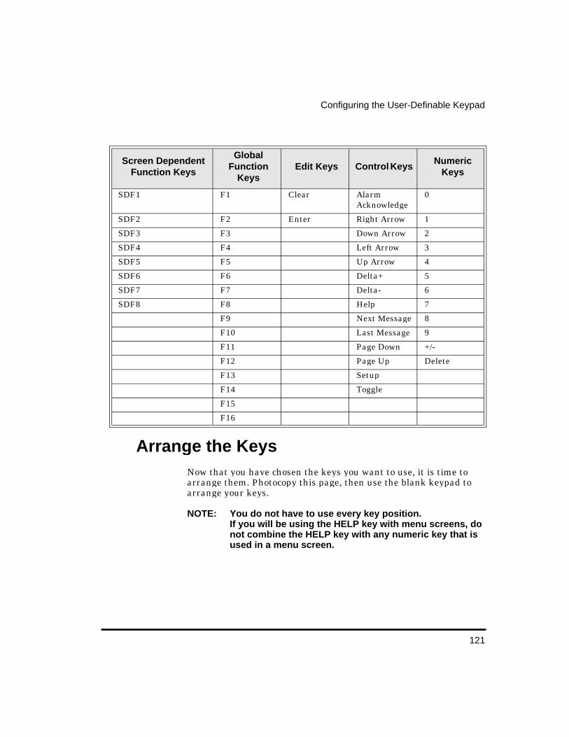
121
Configuring the User-Definable Keypad
Arran ge the Keys Now that you have chosen the keys you want to use, it is time to arrange them. Photocopy this page, then use the blank keypad to arrange your keys.
NOTE: You do not have to use every key position.If you will be using the HELP key with menu screens, do not combine the HELP key with any numeric key that is used in a menu screen.
Screen Dependent Function Keys
Global Function
Keys Edit Keys Control Keys
Numeric Keys
SDF1 F1 Clear Alarm Acknowledge
0
SDF2 F2 Enter Right Arrow 1
SDF3 F3 Down Arrow 2
SDF4 F4 Left Arrow 3
SDF5 F5 Up Arrow 4
SDF6 F6 Delta+ 5
SDF7 F7 Delta- 6
SDF8 F8 Help 7
F9 Next Message 8
F10 Last Message 9
F11 Page Down +/-
F12 Page Up Delete
F13 Setup
F14 Toggle
F15
F16
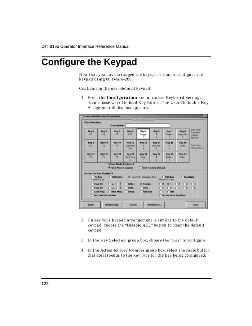
122
OIT-3165 Operator Interface Reference Manual
Confi gure the Keypad Now that you have arranged the keys, it is time to configure the keypad using OITware-200.
Configuring the user-defined keypad:
1. From the Configuration menu, choose Keyboard Settings, then choose User-Defined Key Editor. The User-Definable Key Assignment dialog box appears.
2. Unless your keypad arrangement is similar to the default keypad, choose the “Disable ALL” button to clear the default keypad.
3. In the Key Selection group box, choose the “Key” to configure.
4. In the Action for Key Number group box, select the radio button that corresponds to the key type for the key being configured.

123
Configuring the User-Definable Keypad
5. If configuring a global function key, in the “Fn Key” scroll box, select the global function key number for this key. Must be from 1 to 16.
6. If configuring a screen dependent function key, in the “SDFn Key” scroll box, select the screen dependent function key number for this key. Must be from 1 to 8.
7. If configuring a control, numeric, or control/numeric key:
• In the Control Key group box, select the radio button that corresponds to the control function for this key.
• In the Numeric Key group box, select the radio button that corresponds to the numeric function for this key.
8. If configuring an edit key, in the Edit Key group box, select the radio button that corresponds to the edit function for this key.
9. Repeat steps 3 through 8 for each key.
10. Choose the Done button to return to the OITware-200 main screen.
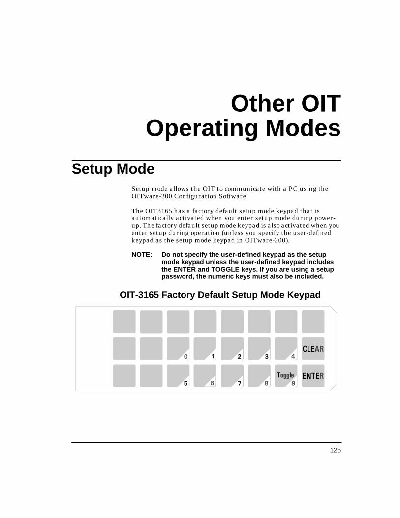
125
Other OITOperatin g Modes
Setup Mode Setup mode allows the OIT to communicate with a PC using the OITware-200 Configuration Software.
The OIT3165 has a factory default setup mode keypad that is automatically activated when you enter setup mode during power-up. The factory default setup mode keypad is also activated when you enter setup during operation (unless you specify the user-defined keypad as the setup mode keypad in OITware-200).
NOTE: Do not specify the user-defined keypad as the setup mode keypad unless the user-defined keypad includes the ENTER and TOGGLE keys. If you are using a setup password, the numeric keys must also be included.
OIT-3165 Factory Default Setup Mode Keypad
OIT-3165 Operator In-
126
OIT-3165 Operator Interface Reference Manual
To specify the user-defined keypad as the setup mode keypad:
1. From the Configuration menu, choose Keyboard Settings, then choose User-Defined Key Editor. The User-Definable Key Assignment dialog box appears.
2. In the Setup Mode Keyboard group box, select the “Use Above Layout” radio button.
3. Choose the Done button to return to the OITware-200 main screen.
To enter setup mode:
1. If the OIT is already powered, press the SETUP key once (on the user-defined keypad) or the ENTER key three times (on the user-defined keypad). The “Setup Password:” message should appear. At this point the factory default setup mode keypad is active.
2. If the OIT is not powered, while applying power to the OIT, press and hold the bottom key on the right side of the keypad while the “<<< Initializing >>>” message appears. The “Setup Password:” message should appear. At this point the setup mode keypad specified in OITware-200 is active (it can be the factory default or the user-defined keypad).
NOTE: 1. To exit configuration mode, press the CLEAR key.
2. If the “<<< Initializing >>>” message is followed by “Connecting to PLC!”, the OIT did not enter setup mode and you need to repeat step 1.
3. If the OIT’s display remains blank and you hear a steady beeping, the OIT does not contain a complete project and is waiting in download mode for OITware-200 to download a project. For instructions on downloading a project from OITware-200, refer to the Downloading an OITware-200 Project section.
3. Type the setup password and then press the ENTER key. If there is no setup password, just press the ENTER key. The “Dn/Upload Mode? YES” message should appear.
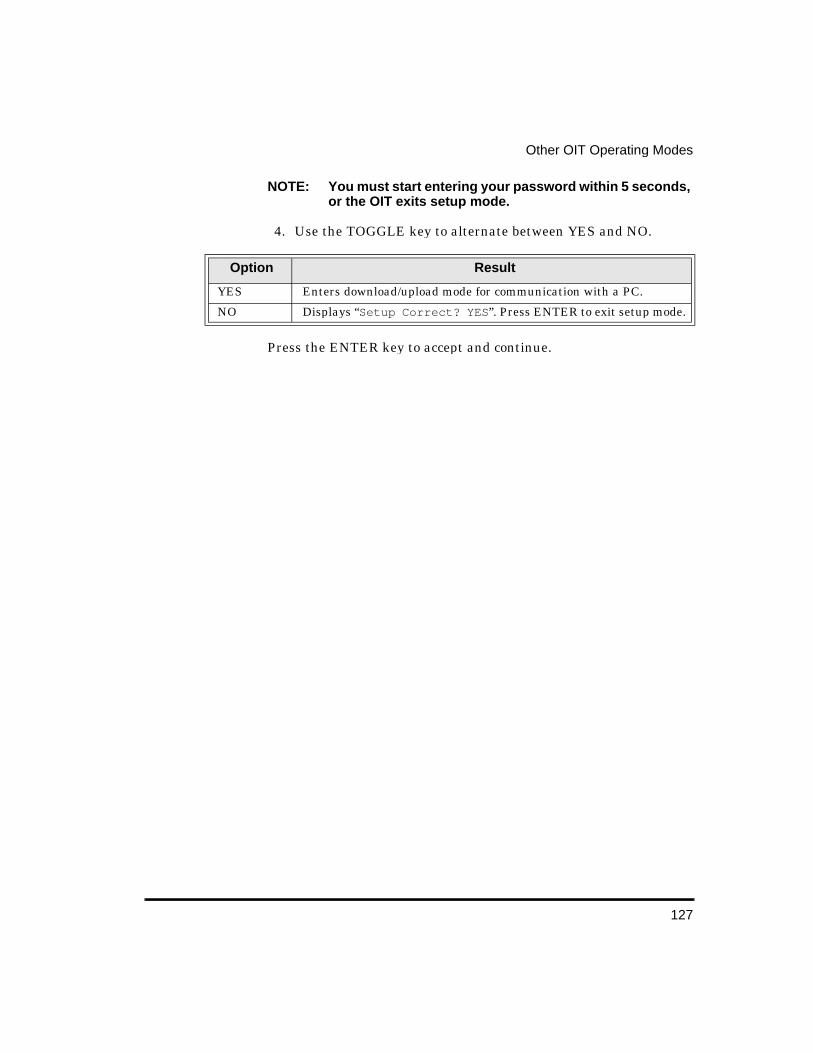
127
Other OIT Operating Modes
NOTE: You must start entering your password within 5 seconds, or the OIT exits setup mode.
4. Use the TOGGLE key to alternate between YES and NO.
Press the ENTER key to accept and continue.
Option Result
YES Enters download/upload mode for communication with a PC.
NO Displays “Setup Correct? YES ”. Press ENTER to exit setup mode.
129
Utilities
Read Pro ject from OIT This utility makes it possible for OITware-200 to read an existing project file from an OIT.
To read a project from an OIT:
1. Perform the following steps:
• Connect the OIT to the PC.
• Place the OIT in Download/Upload Mode.
2. Start OITware-200.
3. From the Transfer menu, choose Read from OIT. The OITware 200 - Read From OIT dialog box appears.
4. Choose the Options button. The Communication Options dialog box appears.
5. In the Upload & Download group box, select the “COM” port radio button that corresponds to the COM port the OIT is connected to. If you are unsure, choose the Auto Detect button.
NOTE: To use the Auto Detect feature, the OIT must be in download/upload mode and properly connected to the PC.
6. If you want the project automatically saved after it is read from the OIT, select the “Prompt For Save As Project?” check box. If this box is checked, you will be prompted to enter a file name for the project.
7. Choose the Done button to return to the OITware 200 - Read From OIT dialog box.
OIT-3165 Operator In-

130
OIT-3165 Operator Interface Reference Manual
8. Choose the OK button to start the transfer.
Export Project to OIT This utility makes it possible to export an existing OITware-200 project to a different OIT model.
To export an OITware-200 project to a different OIT model:
1. Open the original project in OITware-200.
2. From the File menu, choose Export To OIT, then choose the new OIT model.
3. If a warning message appears, choose the OK button to continue or the CANCEL button to stop.
4. The Export Current Project To An OIT dialog box appears. Select the name and directory location for the new project, then choose the OK button.
5. When the export completes, the original project will still be active in OITware-200. To open the new project, from the File menu, choose Open. Select the new project and then choose the OK button.
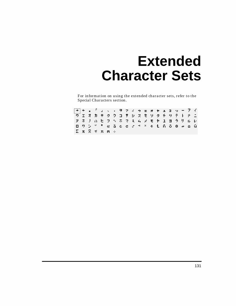
131
ExtendedCharacter Sets
For information on using the extended character sets, refer to the Special Characters section.
OIT-3165 Operator In-

133
Slide-in Le gendTemplates
The OIT-3165 contains a clear window that allows you to insert your own legends to customize the text, colors and graphics of certain keys. These legends can be inexpensively made and are environmentally sealed when installed.
The slide-in legends can be made on any non-glossy stock between 0.004 inches [0.1 mm] and 0.008 inches [0.2 mm] thick by using either of the following methods:
• Photocopy a blank legend and hand illustrate. Refer to the Blank Legends for Photocopying section.
• Use the dimensions to create a computer generated legend. Refer to the Dimensions for Computer Generated Legends section.
Refer to the Installation Manual shipped with your OIT for instructions on installing the slide-in legends.
Blank Le gends for Photocop ying The blank legends on the following pages can be photocopied and hand illustrated to create custom slide-in legends.
When photocopying:
• Use only non-glossy stock which is 0.004 - 0.008 inches [0.1 - 0.2 mm] thick.
• Check photocopy accuracy with the printed check dimension.
When illustrating:
OIT-3165 Operator In-

134
OIT-3165 Operator Interface Reference Manual
• Use the tick marks to locate the switch centers. Refer to the dimension in the Dimensions for Computer Generated Legends section if unsure.
NOTE: Pressing the center of the switch is critical for switch actuation.
• Recommended key size is 0.500 inches [12.7 mm] square.
• Background colors should extend to the solid lines.
• All text and graphics should be 0.070 inches [1.8 mm] within the solid lines.
NOTE: Do not affix anything to the legend using glue, tape, stickers, etc.
OIT-3165A Legend

135
Slide-in Legend Templates
Dimensions for Computer Generated Legends
The dimensions on the following pages can be used to create legends using a computer graphics program.
When creating:
• Dimensions are in inches [mm].
• Recommended key size is 0.500 inches [12.7 mm] square.
NOTE: Pressing the center of the switch is critical for switch actuation.
• Background colors should extend to the upper and lower edges of the legend and to the 2 vertical lines marked “BACKGROUND.”
• All text and graphics should be within the dashed rectangle.
When printing:
• Use only non-glossy stock which is 0.004 - 0.008 inches [0.1 - 0.2 mm] thick.
• Check printing accuracy.

136
OIT-3165 Operator Interface Reference Manual
OIT-3165A Legend

137
Troubleshootin g
Displa y Bri ghtness and Viewin g Angle Can the LCD Viewin g Angle be Chan ged?
Yes. To change the LCD viewing angle on the OIT-3165 in OITware-200 press SHIFT+F4 to open the OIT General Settings dialog box. In the LCD Contrast group box, select the appropriate radio button.
OIT Operation OIT is Not Displayin g Expected Information on the Display
Possible Causes: • The OIT does not contain the entire OITware-200 project, OIT
operational software or PLC protocol software.
• The OITware-200 project was not configured to do what you expect.
Possible Solutions: • Download the OITware-200 project, OIT operational software,
and PLC protocol software to the OIT again. Follow the steps in the Downloading an OITware-200 Project section. Observe the messages on both the PC and OIT. Note any messages that indicate a problem.
• Review the OITware-200 project.
OIT-3165 Operator In-
138
OIT-3165 Operator Interface Reference Manual
When the PLC Requests the Same Screen Twice the Screen is Not Displayed
Possible Cause: • If the MRR already contained the screen number that the PLC
requested, the OIT would not recognize the screen request.
Possible Solution: • Modify the PLC program so that when the MRR already
contains the screen number that the PLC is requesting, the PLC writes a zero to the MRR before writing the screen number.
• Activate the Clear Register/Bit After Receiving Screen Request feature. Refer to the Configuring the MRR with Enhanced Features section.
OITware-200 “Out of Memory”
Possible Cause: • The computer does not have sufficient resources to run
OITware-200.
Possible Solution: • Use a computer that has at least 4MB of RAM.
“Timeout Detected. OIT did not respond.”
Possible Causes: • The OIT is not connected to the PC or is not in Download/
Upload Mode.
• OITware-200 is not using the correct COM port.
• The configuration cable is not wired correctly.

139
Troubleshooting
• The configuration cable is not connected to the correct port on the OIT or the PC.
• If your OIT has two serial ports, something is connected to the RTS/CTS lines on port 1.
Possible Solutions: • Verify that the configuration cable is wired correctly and is in
good condition.
• Follow the steps in the Downloading an OITware-200 Project section.
• If your OIT has two serial ports, verify nothing is connected to the RTS/CTS lines on port 1.
OIT to PLC Communication “Cannot Connect To PLC Durin g Startup. *** Re-connect in pro gress ***”or “Can’t connect to PLC. Retry in Pro gress!”
Possible Causes: • The PLC’s mode switch is not in the correct position.
• The PLC password in the OIT does not match the PLC.
• The communication settings (baud rate, parity, data bits, stop bits) for the OIT and PLC do not match.
• The communication cable is not wired correctly.
• The communication cable is not connected to the correct port on the OIT or PLC.
• The wrong PLC protocol was downloaded to the OIT.
140
OIT-3165 Operator Interface Reference Manual
Possible Solutions: • Verify that your PLC’s mode switch (if applicable) is in the
correct position. The switch may need to be in a mode other than run mode; such as terminal mode or xxxxxx mode. Refer to your controller operations manual or the applicable Controller Information Sheet from EMERSON Motion Control.
• Verify that the PLC password in the OIT matches the password in your PLC. In OITware-200 press F4 to open the OIT - Controller Settings dialog box. In the Password group box, enter the correct PLC password.
• Verify that the communication settings in the OIT and PLC match. In OITware-200 press F4 to open the OIT - Controller Settings dialog box. In the OIT - Controller Serial Communications Settings group box, select the correct communication settings.
• Verify that the communication cable is wired correctly and in good condition.
• Verify that the OIT and PLC are connected correctly. Refer to the OIT-3165 Operator Interface Installation Manual that came with the OIT.
• Download the project with the correct PLC protocol from OITware-200. Follow the steps in the Downloading an OITware-200 Project section.
“Cannot write to Ms g Request Re gister!”or “Error: Settin g up Mailbox Durin g Startup”
Possible Cause: • The PLC address for the Message Request Register (MRR) is
outside the memory supported by the PLC’s CPU.
141
Troubleshooting
Possible Solution: • Change the PLC address for the MRR. In OITware-200 press
SHIFT+F6 to open the OIT Message Control Settings dialog box. In the Message Request Register group box, select a supported PLC address. If you are using the MRR enhanced features, to set the PLC address(es) for the MRR(s), refer to the Configuring the MRR section.
“Cannot write to the Status Coils!” or“Error: Settin g up StatusCoils On Startup” or“Cannot set the Reset Status Coil!” or“Error: Settin g STAT_RESET durin g Startup” or“Cannot set the Alarm Empty Status Coil!” or“Error: Settin g ALM_EMPTY Durin g Startup”
Possible Cause: • The PLC address for the Status Coils is outside the memory
supported by the PLC’s CPU.
Possible Solution: • Change the PLC address for the Status Coils. In OITware-200
press F4 to open the OIT - Controller Settings dialog box. In the Status Coils group box, select a supported PLC address.
“Cannot write to the Function Key Coils!” or “Error: Settin g up KeyCoils On Startup”
Possible Cause: • The PLC address for the Function Key Coils is outside the
memory supported by the PLC’s CPU.
142
OIT-3165 Operator Interface Reference Manual
Possible Solution: • Change the PLC address for the Function Key Coils. In
OITware-200 press F5 to open the Function Key Editor dialog box. In the Coil Address group box, select a supported PLC address.
Alarms How Many Alarms are Supported?
Each OIT can store and display up to 500 screens. Of these 500 screens, any or all can be alarms.
How are Alarms Displayed?
The PLC requests an alarm screen by placing the number that corresponds to that screen in the Message Request Register (MRR). When the OIT reads the number in the MRR, the OIT displays the corresponding alarm screen, sounds the audible alert, and blinks the alarm LED. Refer to the Alarm Screens section for more information.
What Happens When the OIT Operator Pushes the Alarm Ack Key?
The audible alert is silenced, the alarm LED is cleared, and the Acknowledge Alarm status coil is set. If the alarm stack contains additional alarms, the next alarm in the stack is displayed. Otherwise, the prior non-alarm screen is displayed.
Is There an Alarm Stack?
Yes, but only for pending alarms. Once the OIT operator acknowledges an alarm screen, the alarm request is terminated and discarded.
143
Troubleshooting
Alarms are Cleared Before the OIT Operator Ac-knowled ges Them
Possible Cause: • The PLC is setting the Clear Alarm or Clear Alarm Stack status
coil.
Possible Solution: • Modify the PLC program so that the PLC does not set the Clear
Alarm or Clear Alarm Stack status coils. From the starting PLC address for the status coils, the Clear Alarm status coil is offset 7 bits and the Clear Alarm Stack status coils is offset 8 bits. To determine the starting PLC address for the status coils, press F4 in OITware-200. The OIT - Controller Settings dialog box appears. The Status Coils group box contains the starting PLC address for the status coils.
When the PLC Requests the Same Alarm Twice the Alarm is Not Displayed
Possible Cause: • If the MRR already contained the screen number that the PLC
requested, the OIT would not recognize the screen request.
Possible Solutions: • Modify the PLC program so that when the MRR already
contains the screen number that the PLC is requesting, the PLC writes a zero to the MRR before writing the screen number. This allows the OIT to recognize the alarm request and does not clear the OIT’s display.
• Activate the Clear Register/Bit After Receiving Screen Request feature. Refer to the Configuring the MRR with Enhanced Features section.
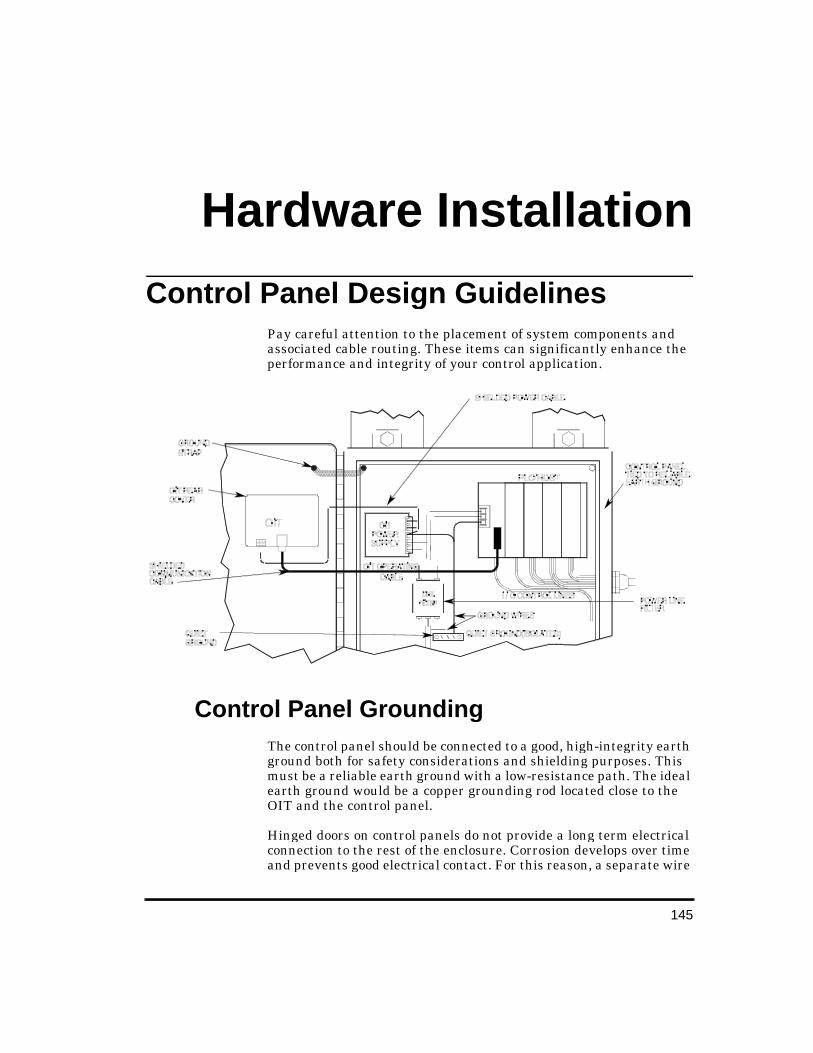
145
Hardware Installation
Control Panel Desi gn Guidelines Pay careful attention to the placement of system components and associated cable routing. These items can significantly enhance the performance and integrity of your control application.
Control Panel Groundin g The control panel should be connected to a good, high-integrity earth ground both for safety considerations and shielding purposes. This must be a reliable earth ground with a low-resistance path. The ideal earth ground would be a copper grounding rod located close to the OIT and the control panel.
Hinged doors on control panels do not provide a long term electrical connection to the rest of the enclosure. Corrosion develops over time and prevents good electrical contact. For this reason, a separate wire
OIT-3165 Operator In-
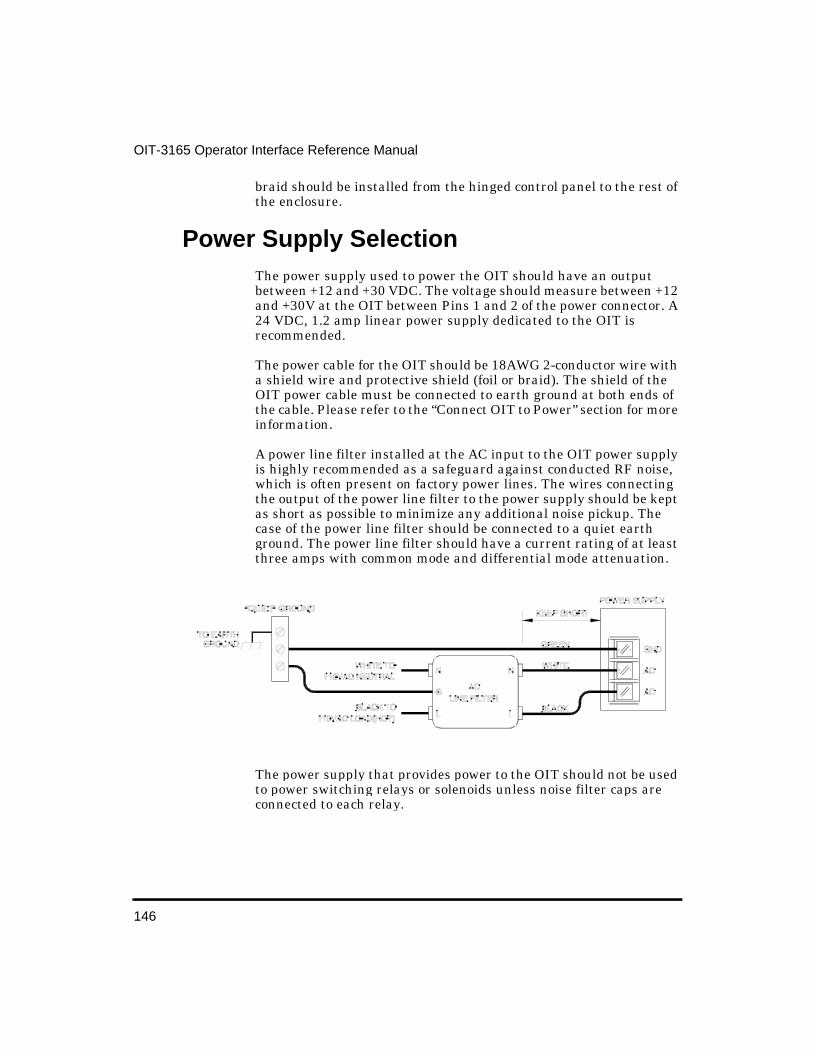
146
OIT-3165 Operator Interface Reference Manual
braid should be installed from the hinged control panel to the rest of the enclosure.
Power Supply Selection The power supply used to power the OIT should have an output between +12 and +30 VDC. The voltage should measure between +12 and +30V at the OIT between Pins 1 and 2 of the power connector. A 24 VDC, 1.2 amp linear power supply dedicated to the OIT is recommended.
The power cable for the OIT should be 18AWG 2-conductor wire with a shield wire and protective shield (foil or braid). The shield of the OIT power cable must be connected to earth ground at both ends of the cable. Please refer to the “Connect OIT to Power” section for more information.
A power line filter installed at the AC input to the OIT power supply is highly recommended as a safeguard against conducted RF noise, which is often present on factory power lines. The wires connecting the output of the power line filter to the power supply should be kept as short as possible to minimize any additional noise pickup. The case of the power line filter should be connected to a quiet earth ground. The power line filter should have a current rating of at least three amps with common mode and differential mode attenuation.
The power supply that provides power to the OIT should not be used to power switching relays or solenoids unless noise filter caps are connected to each relay.
147
Hardware Installation
OIT Cable Routin g Always route the OIT communication cable and power cable away from any AC voltage or PLC/host control wires.
Never bundle the OIT cables together with 120 VAC power wires or with relay wiring.
Try to keep at least 8 inches (20.32 cm) of separation between the OIT cables and other power wiring. If voltages greater than 120 VAC are used in the system, greater separation is required.
If the OIT cables must come near AC wiring, make sure they cross at 90 degrees.
Running AC power wires in a separate grounded conduit is the preferred method for electrical noise reduction.
Keep the lengths of the OIT cables as short as possible. Do not coil excess cable and place it next to AC powered equipment.
Other Steps to Improve Noise Immunity Always install the OIT’s rear cover. This provides a shield against electrical noise which can be generated in the control panel by relays, motors, power lines, and/or high frequency equipment. Ensure that all rear cover mounting screws are properly secured.
Any equipment used in the enclosure that operates at high frequency or high current levels can be covered with a grounded metal shield.
OIT InstallationIt is necessary to follow all installation procedures described in this chapter for electrical noise immunity.
Your OIT is designed to connect easily to your PLC. External connectors provide quick connection for power and communications wiring.
There is one serial port with an RJ-45 shielded jack. This port is used to connect to the PLC and to configure the OIT.

148
OIT-3165 Operator Interface Reference Manual
A separate three-position terminal block is supplied to provide power to the OIT.
Create Custom Slide-In Le gend Please refer to the “Custom Keypad Slide-in Legends” section for details.
Prepare Panel for OIT Mountin g The OIT-3165 is mounted to a control panel from the front. For a proper NEMA 4/12 seal, you will need:
A panel with a maximum thickness of 0.125 inches (3.2 mm).
A panel with a minimum thickness of 16-gauge (0.059 inches; 1.5 mm) steel or 10-gauge (0.102 inches; 2.6 mm) aluminum. Thinner panels may bow between the mounting studs, requiring the use of a stiffener on the rear.
The surface of the panel, where the panel comes into contact with the gasket, must be free of scratches, pits, and other features that prevent the gasket from sealing properly.

149
Hardware Installation
The diagram below shows the dimensions of the panel cutout required for proper installation. The panel cutout should be cleaned and deburred before the OIT is installed.

150
OIT-3165 Operator Interface Reference Manual
Mount OIT to Panel
1. Gently position the OIT with the studs through the panel mounting holes.
2. Secure the OIT by installing the four #6-32UNC mounting nuts using a 5/16 inch socket wrench or nut driver.
RE-INSTALLING: Because the gasket will take a “set” to the panel, be sure to re-install any OIT to the same panel cutout when a NEMA 4/12 seal is required.
Do not torque the 4 mountin g nuts to over 15 pound-inches. Over torquin g can strip the threads or pull the studs loose.
CAUTION!
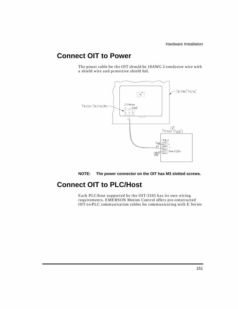
151
Hardware Installation
Connect OIT to Power The power cable for the OIT should be 18AWG 2-conductor wire with a shield wire and protective shield foil.
NOTE: The power connector on the OIT has M3 slotted screws.
Connect OIT to PLC/Host Each PLC/host supported by the OIT-3165 has its own wiring requirements. EMERSON Motion Control offers pre-constructed OIT-to-PLC communication cables for communicating with E Series

drives and AXIMA multi-axis controllers. They are built and tested for high reliability and are strongly recommended.
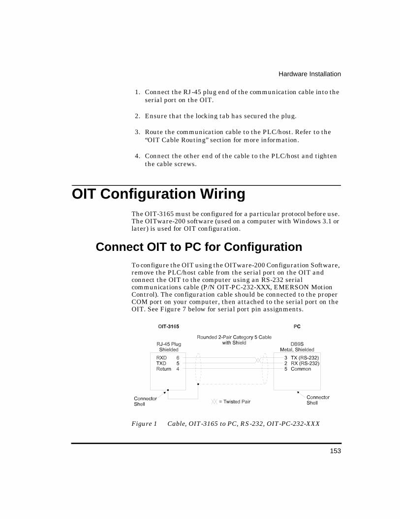
153
Hardware Installation
1. Connect the RJ-45 plug end of the communication cable into the serial port on the OIT.
2. Ensure that the locking tab has secured the plug.
3. Route the communication cable to the PLC/host. Refer to the “OIT Cable Routing” section for more information.
4. Connect the other end of the cable to the PLC/host and tighten the cable screws.
OIT Confi guration Wirin g The OIT-3165 must be configured for a particular protocol before use. The OITware-200 software (used on a computer with Windows 3.1 or later) is used for OIT configuration.
Connect OIT to PC for Confi guration To configure the OIT using the OITware-200 Configuration Software, remove the PLC/host cable from the serial port on the OIT and connect the OIT to the computer using an RS-232 serial communications cable (P/N OIT-PC-232-XXX, EMERSON Motion Control). The configuration cable should be connected to the proper COM port on your computer, then attached to the serial port on the OIT. See Figure 7 below for serial port pin assignments.
Figure 1 Cable, OIT-3165 to PC, RS-232, OIT-PC-232-XXX
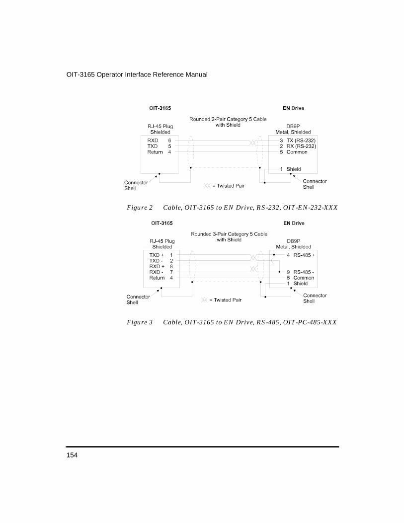
154
OIT-3165 Operator Interface Reference Manual
Figure 2 Cable, OIT-3165 to EN Drive, RS-232, OIT-EN-232-XXX
Figure 3 Cable, OIT-3165 to EN Drive, RS-485, OIT-PC-485-XXX

155
Hardware Installation
Figure 4 Cable, OIT-3165 to AXIMA, RS-485, OIT-AX-485-XXX
Custom Keypad Slide-In Le gends The OIT-3165 has a graphic overlay covering the keypad. This overlay contains a clear window that allows you to insert your own legend to customize the keypad’s text, colors, and graphics. This legend can be inexpensively made and is environmentally sealed when installed.
The slide-in legend can be made on any non-glossy stock between 0.004 inches (0.1 mm) and 0.008 inches (0.2 mm) thick by using any of the following methods:
• Photocopy one of the predefined keypad templates. • Photocopy the blank legend and hand illustrate. • Use the dimensions to create a computer generated legend.

156
OIT-3165 Operator Interface Reference Manual
Predefined Keypad Templates If you have chosen one of the predefined keypad templates in OITware-200, you can photocopy the corresponding slide-in legend from Figure 8.

157
Hardware Installation
Blank Le gend for Photocopyin g The blank legend in Figure 9 can be photocopied and hand illustrated.
When photocopying: • Use only non-glossy stock which is 0.004 - 0.008 inches (0.1 - 0.2
mm) thick.

158
OIT-3165 Operator Interface Reference Manual
• Check photocopy accuracy with the printed check dimension.
When illustrating:
Use the tick marks to locate the switch centers. Refer to the computer generated legend dimensions if unsure.
NOTE: Pressing the center of the switch is critical for switch actuation.
• Recommended key size is 0.500 inches [12.7 mm] square.
• Background colors should extend to the solid lines.
• All text and graphics should be 0.07 inches [1.78 mm] within the solid lines.
NOTE: Do not affix anything to the legend using glue, tape, stickers, etc.
Creatin g a Computer-Generated Slide-In Le gend
The dimensions in Figure 10 can be used to create a computer generated legend.
When creating: • Dimensions are in inches [mm]. • Recommended key size is 0.500 inches [12.7 mm] square.
NOTE: Pressing the center of the switch is critical for switch actuation.
• Background colors should extend to the upper and lower edges of the legend and to the 2 vertical lines marked “BACKGROUND.”
• All text and graphics should be within the dashed rectangle.
When printing: • Use only non-glossy stock which is 0.004 - 0.008 inches (0.1 - 0.2
mm) thick.
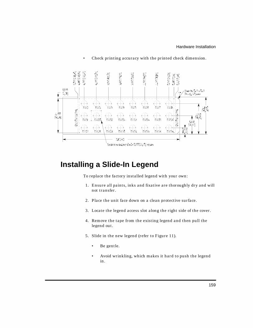
159
Hardware Installation
• Check printing accuracy with the printed check dimension.
Installin g a Slide-In Le gend To replace the factory installed legend with your own:
1. Ensure all paints, inks and fixative are thoroughly dry and will not transfer.
2. Place the unit face down on a clean protective surface.
3. Locate the legend access slot along the right side of the cover.
4. Remove the tape from the existing legend and then pull the legend out.
5. Slide in the new legend (refer to Figure 11).
• Be gentle.
• Avoid wrinkling, which makes it hard to push the legend in.

160
OIT-3165 Operator Interface Reference Manual
• If the legend moves around too much, put a curl in the paper.
NOTE: The legends are made long to facilitate removal.
6. Once installed, tape the end of the legend to the cover to secure it.
OIT-3165 Hardware Specifications Mechanical
Material: Aluminum sealed to NEMA 4/12 when panel mounted
Mounting: Panel
Wiring: Unit is field-wired by user to external power plug and shielded RJ-45 communications connectors
Weight: 1 pound (0.45 kg)
Environmental
Operating Temp: +32 to +122°F (0 to +50°C)
Storage Temp: -4 to +158°F (-20 to +70°C)
161
Hardware Installation
Electric Noise Immunity (pending CE approval)
Emissions: EN55011 (Group 1, Class B)—Generic commercial, light, and heavy industrial environments
EN50081-1—Generic domestic and light industrial environments
EN50081-2—Generic heavy industrial environment
Immunity: EN50082-1—Generic domestic and light industrial environments
EN50082-2—Generic heavy industrial environment
Power Requirements
Input Voltage: 12 to 30 VDC
Power Usage: 2.5 watts typical
Display
Display Type: Backlit Liquid Crystal Display (LCD)—5 x 7 dot matrix with cursor
Display Character Size: 2 lines of 20 characters, 0.19 inches (4.8 mm) high
Display Viewing Angle: Approximately 90 degrees
Keypad
Key Type: Membrane switch with custom legending (all keys)
Feedback: Audible
Layout: 24 user-definable keys arranged in 3 rows
Operational Life: Three million operations
Communications
Serial Port: RS-232, RS-422, or RS-485
Baud Rates: 300, 600, 1200, 2400, 4800, 9600, or 19.2k
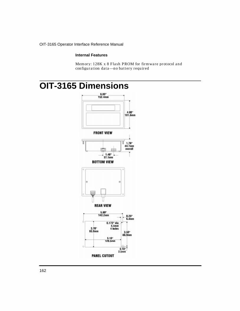
162
OIT-3165 Operator Interface Reference Manual
Internal Features
Memory: 128K x 8 Flash PROM for firmware protocol and configuration data—no battery required
OIT-3165 Dimensions
163
PLC Protocol GuideEMERSON Motion Control Operator Interface OIT-3165 can communicate with the EMERSON Motion Control E Series drives, (including the EN-204, EN-208 and EN-214 models) and AXIMA multi-axis motion controllers. The OITs use a variation of the Modbus RTU protocol that allows the OIT to act as a master when communicating to the EMERSON products. This protocol driver allows a single OIT to connect to single or multiple E Series drives or AXIMA controllers.
Connecting to each EMERSON product is made directly through the Modbus port which is located on the front of the E Series drive or on the left side of the AXIMA controller. The Operator Interface Terminal will not begin normal operation until it can communicate with the EMERSON product. Therefore, the communications parameters for the OIT must exactly match the communications settings for the EMERSON product.
PLC to OIT Communications Settin gs When starting a new project file for the OIT using OITware 200, you must enter the Configuration Editor to configure the communications settings that the OIT will use when connecting to the EMERSON product. Use the suggested default settings given below, unless the drive’s communications parameters are different:
Message Request Register
Default: DisabledRange: 00001 to 49999
The message request register is the 16-bit register in the EMERSON products that the OIT will check to see if the drive wants to display a screen. The default is disabled but you can choose any 16-bit register or sixteen consecutive coils in the device’s memory table.
OIT-3165 Operator In-
164
OIT-3165 Operator Interface Reference Manual
Function Key Coils
Range: 00001 to 49999
The function key of the OIT can control coils in the EMERSON product when the function keys are configured as push on/off, momentary or latched. The protocol allows you to choose any register or coil address in the drive’s memory table.
Status Coils
Default: DisabledRange: 00001 to 49999
The status coils register is the 16-bit PLC register that the OIT will read/write to for status bit information that is shared by the OIT and the EMERSON product. The default is disabled but you can choose any 16-bit register or sixteen consecutive coils in the EMERSON product’s memory table. The least significant bit corresponds to the Message Received status coil (example: 00385 = MsgRcvd, 00386 = InvalidMsg, etc. if 00385 is selected).
NOTE: The default selection may generate an error screen on the OIT when it first attaches to the EMERSON product if the selection is out of range for the memory map of that drive. If this occurs, then a lower number in the memory range must be used (example: 00001).
Address
Does not apply to EMERSON Motion Control products.
Source Address
Does not apply to EMERSON Motion Control products.
165
PLC Protocol Guide
Destination Address
Default: 1Range: 0 to 247
This is the address used by the EMERSON product on the Modbus network. The OIT cannot communicate with the device unless this setting matches the network address configured for the EMERSON product. The default network address most often used by the EMERSON product is 1, but consult your operations manual if you are experiencing problems communicating to the EMERSON product.
Password
Does not apply to EMERSON Motion Control products.
Baud Rate
Default: 19200 baudAlso available: 300, 600, 1200, 2400, 4800, 9600, 19200 baud
This is the baud rate that the OIT uses to communicate with the device. Check your EMERSON product’s Modbus port to ensure that the baud rate matches this setting. Lower baud rates will dramatically slow down the OIT’s ability to monitor registers so the fastest baud rate allowed by the drive should always be used. The default baud rate most often used by the EMERSON product is 19200, but consult your operations manual if you are experiencing problems communicating with the EMERSON product.
Parity
Default: NoneAlso available: Even, Odd, None, Mark, Space
This is the parity that the OIT uses to communicate with the device. Check your device’s Modbus port to ensure that the parity matches this setting. The default parity setting most often used by the EMERSON product is no parity, but consult your operations manual if you are experiencing problems communicating with the drive.
166
OIT-3165 Operator Interface Reference Manual
NOTE: When using even or odd parity use 1 stop bit, if using no parity use 2 stop bits.
Data Bits
Default: 8 bitsAlso Available: 7 or 8 bits
This is the character length, specified in bits, that the OIT uses to communicate with the EMERSON product. Check your EMERSON product’s Modbus port to ensure that the data length matches this setting. The default data length setting most often used by the EMERSON product is 8 bits, but consult your operations manual if you are experiencing problems communicating with the EMERSON product.
Stop Bits
Default: 2 bitsAlso available: 1 or 2 bits
This is the stop bits per character that the OIT uses to communicate with the device. Check your EMERSON product’s Modbus port to ensure that the stop bit length matches this setting. The default stop bit length setting most often used by the EMERSON product is 2 bits, but consult your operations manual if you are experiencing problems communicating with the EMERSON product.
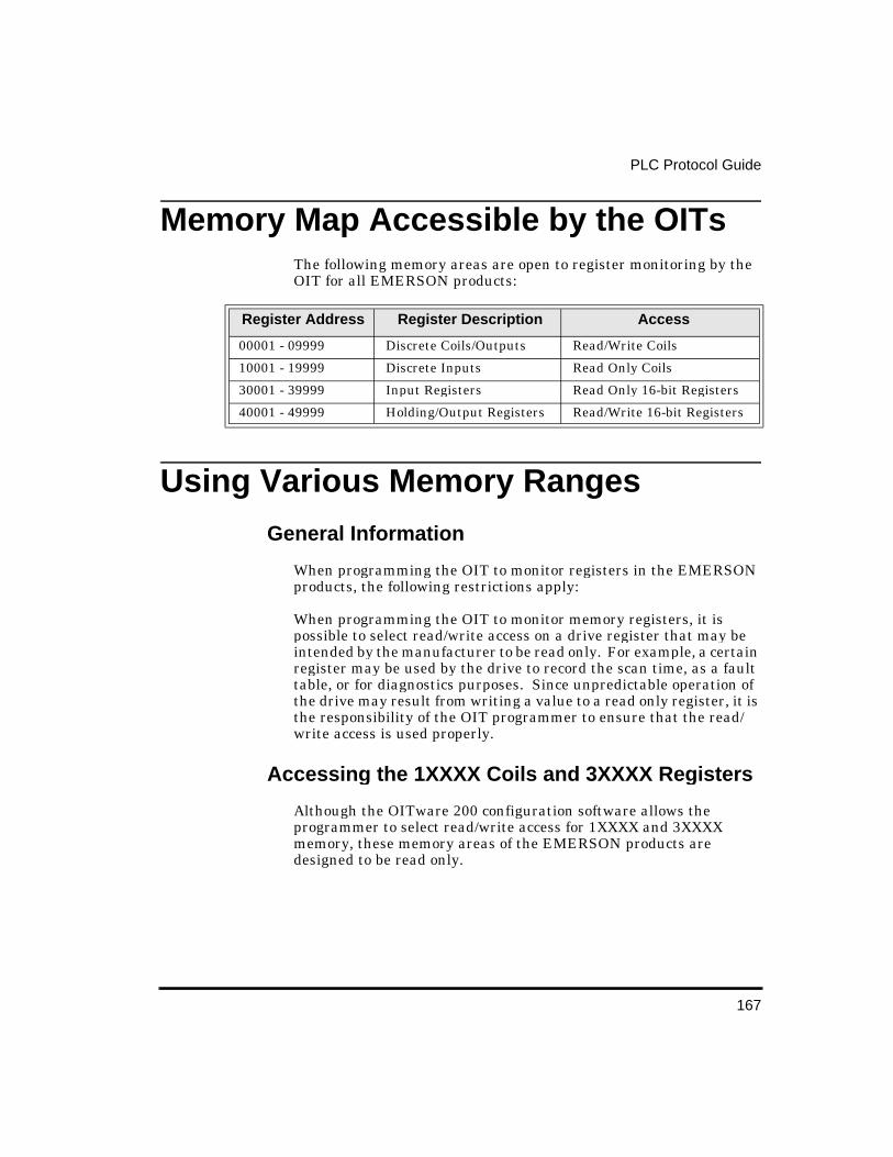
167
PLC Protocol Guide
Memory Map Accessible by the OITs The following memory areas are open to register monitoring by the OIT for all EMERSON products:
Usin g Various Memory Ran ges General Information
When programming the OIT to monitor registers in the EMERSON products, the following restrictions apply:
When programming the OIT to monitor memory registers, it is possible to select read/write access on a drive register that may be intended by the manufacturer to be read only. For example, a certain register may be used by the drive to record the scan time, as a fault table, or for diagnostics purposes. Since unpredictable operation of the drive may result from writing a value to a read only register, it is the responsibility of the OIT programmer to ensure that the read/write access is used properly.
Accessin g the 1XXXX Coils and 3XXXX Re gisters
Although the OITware 200 configuration software allows the programmer to select read/write access for 1XXXX and 3XXXX memory, these memory areas of the EMERSON products are designed to be read only.
Register Address Register Description Access
00001 - 09999 Discrete Coils/Outputs Read/Write Coils
10001 - 19999 Discrete Inputs Read Only Coils
30001 - 39999 Input Registers Read Only 16-bit Registers
40001 - 49999 Holding/Output Registers Read/Write 16-bit Registers
168
OIT-3165 Operator Interface Reference Manual
On usin g Bank 8 or Bank 16 formats
When using these formats, each drive coil (bit) is individually displayed in terms of 1 and 0, with the lowest addressed coil displayed in the right-most position in the field. Therefore, if using coils 00001-00016 is the most significant bit displayed in the left-most position and 00001 is the least significant bit displayed in the right-most position.
On usin g BCD4, Signed, or Decimal formats
If a coil address is used (0XXXX or 1XXXX) then the specified address is the least significant bit of the register monitor and the next 16 consecutive coils are used.
On usin g BCD8 or Lon g formats
When using these formats, if a 16-bit memory address is used (3XXXX or 4XXXX) the specified address is the most significant word of the register monitor with the next consecutive address representing the least significant word of the register. For example, suppose register 40001 is displayed as a register monitor on the OIT using BCD8 format. The current value in register 40001 is 0x1234 and the current value is register 40002 is 0x5678. The OIT would display register monitor 40001 as 12345678.
If a coil address is used (0XXXX or 1XXXX) then the specified address is the least significant bit of the register monitor and the next 31 consecutive coils are used.
Cable Connections
The EMERSON Motion Control’s OIT-3165 Operator Interface Terminal is connected to the EMERSON product using the female DB-9 connector (J4) located on the front of the drive or AXIMA multi-axis controller using the male DB-9 connector located on the side of the AXIMA. (requires Modbus option). The serial interface is either three wire non-isolated RS232C or two wire non-isolated RS-485.
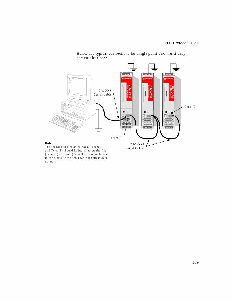
169
PLC Protocol Guide
Below are typical connections for single point and multi-drop communications:
Note:The terminating resistor packs, Term-Hand Term-T, should be installed on the first(Term-H) and last (Term-T) E Series drivesin the string if the total cable length is over50 feet.
TIA-XXXSerial Cable
Term-H
Term-T
D D S - X X XSerial Cables
D D S - X X XSerial Cables

171
Cable Dia grams
E Series Drives Cables
OIT-3165 Operator In-
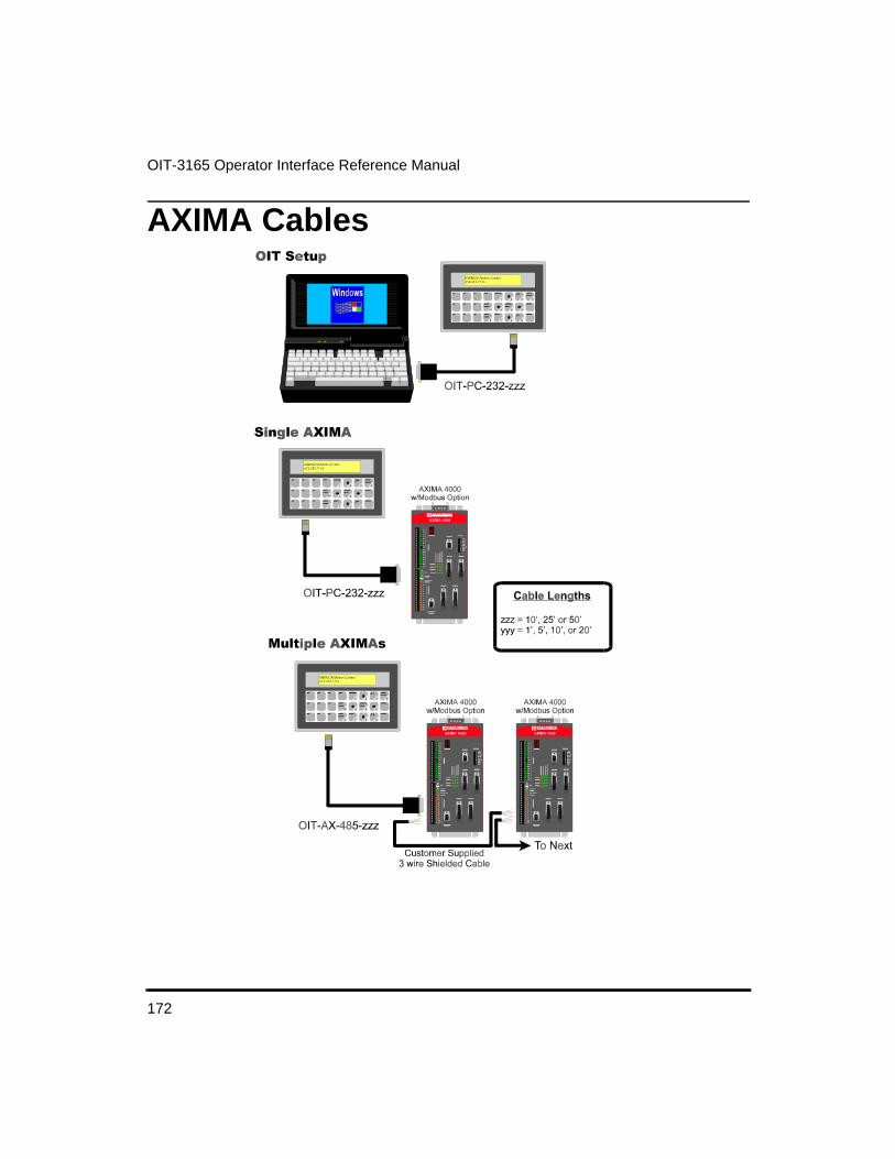
172
OIT-3165 Operator Interface Reference Manual
AXIMA Cables

173
Cable Diagrams
Cable Wirin g Diagrams
OIT-PC-232-XXX Cable
Figure 5 Cable, OIT-3165 to PC, RS-232, OIT-PC-232-XXX
OIT-EN-232-XXX Cable
Figure 6 Cable, OIT-3165 to EN Drive, RS-232, OIT-EN-232-XXX

174
OIT-3165 Operator Interface Reference Manual
OIT-PC-485-XXX Cable
Figure 7 Cable, OIT-3165 to EN Drive, RS-485, OIT-PC-485-XXX
OIT-AX-485-XXX Cable
Figure 8 Cable, OIT-3165 to AXIMA, RS-485, OIT-AX-485-XXX


![Competencias Laborales OIT[1]](https://static.fdocuments.us/doc/165x107/55cf94d0550346f57ba48e5d/competencias-laborales-oit1-569d755087727.jpg)