
oilseals.pdf
28
Oil Seals s e a l i n g t e c h n o l o g y
-
Upload
eslaam-elsaid -
Category
Documents
-
view
219 -
download
0
Transcript of oilseals.pdf

7/26/2019 oilseals.pdf
http://slidepdf.com/reader/full/oilsealspdf 1/28

7/26/2019 oilseals.pdf
http://slidepdf.com/reader/full/oilsealspdf 2/28
+31 72 514 15 14
+31 72 514 18 33
semi-manufactured and finishedproducts of:Eriflon-PTFE - PVDF - PCTFEErtalon - PA6 and PA66Ertacetal - POMErtalyte - PETPNylatronFluorosintTorlonTechtronPEEK/PSU/PEIMeldin-PITrovidur/Epradur PVCMultilene PE and PPpolycarbonateacrylate - PMMA - PET Epratex/Tufnol-PF (laminated fabric)
Hapa - PF (laminated paper)RX® Grate/GVK (glass-fibrereinforced plastics)Erlan/Rhino Hyde®-PUR
Should you need a product youcannot find on this page, pleasecall one of our ERIKS Servicecenters(see on the back of this cover).
+31 72 514 18 55
pipes and fittings of:- Superflo ABS- Air-Line Xtra- PE- PP- PVC- PVC-C- PVDF ball valvesdiaphragm valvesbutterfly valvesglobe valvescheck valvesstrainersoverflow valvesreducing valvessolenoid valves
clampstoolscementsplastic tankswall sleevesrepair clamps
oil sealsEri-sleeves shaft protecting V-ringsPS sealsseals, guide parts and wipersfor hydraulic and pneumaticcylindersMultisealsOmniseals® spring actuatedPTFE sealsend caps
KVSP Kalrez® valve stempackingslubricantsgreasesleak detection spraysliquid sealants
+31 72 514 18 11
+31 72 514 18 66
+31 72 514 18 22
rubber vormartikelenrubber moulded partsprofiles of:- cellular rubber- sponge rubber- solid rubberinflatable sealsO-ringsX-ringsback-up ringscords
adhesivesboxes of assorted O-ringsvibration absorbers
hoses of:- rubber- plastic- PTFE- metalhose couplingscoupling systemshose clampshose reelshose reel cartshydraulic hosesfittings and couplings forhydraulicsexpansion joints of:- rubber- metal- fabric
- PTFE
metallic and semi-metallicgaskets:- spiral wound- ring type joint- serrated- insulating setsflange gaskets and die-cutparts of:- elastomers- fibre sheet- PTFE sheet/tape
- graphite sheetstuffing-box packingsmechanical seals
klepafsluitersglobe valvesgate valvescheck valvesstrainerssight glassessteam trapsreducing valvessafety valvesgauge glassesoverflow valvesvacuum and air reliefe valvesball valvesbutterfly valvespneumatic and electricactuatorsdiaphragm valvespinch valves
measurement and regulationcomponents for: - pressure- temperature- flow- levelcontrol valvessolenoid valves
+31 72 514 18 44
Easy accessible dia direct phone numbers
You can also consult ourOnline-Catalog with over45,000 products in stock.
www.eriks.nl
+31 72 514 18 00
PLASTIC PIPINGHOSES, ACCESSORIES
AND EXPANSION JOINTSINDUSTRIAL PLASTICS
VALVES ANDINSTRUMENTATION
FLANGEGASKETS, MECHANICAL
SEALS AND PACKINGS
DYNAMICSEALS
O-RINGS & TECHNICAL RUBBER
GENERAL

7/26/2019 oilseals.pdf
http://slidepdf.com/reader/full/oilsealspdf 3/28
Oil Seals
ERIKS bv
PO Box 280
NL-1800 BK Alkmaar
T +31 72 514 15 14
F +31 72 515 56 45
www.eriks.nl
847033-2007
7/26/2019 oilseals.pdf
http://slidepdf.com/reader/full/oilsealspdf 4/28
O I L S E A L S
2
Contents
ERIKS OIL SEALS TECHNICAL MANUAL
1. Introduction ..................................................................................3
2. Description and principle of Oil Seals ........................................4
3. Construction of Oil Seals ............................................................5
4. Common types ...........................................................................6
5. Common materials ................................................................... 11
6. Shaft materials, seal tolerance and housing ............................ 14
7. Shaft eccentricity and shaft runout ..........................................15
8. Materials and tolerances of the shaft .......................................16
9. Lubrication ................................................................................ 17
10. Oil Seals for higher pressures .................................................. 18
11. Split Oil Seals ............................................................................19
12. Assembly of the Oil Seal ...........................................................21
13. Troubleshooting ........................................................................2314. Conversion table inch / mm ...................................................... 24
15. Table of DIN dimensions ...........................................................25
Disc la imer
The information provided in this document is for general information purposes
only and does not constitute advice. ERIKS shall not be liable for any damages resulting from the use of this document, including but not limited to damagescaused by any incorrectness or incompleteness of the provided information,unless such damage is the result of any wilful misconduct or gross negligenceon part of ERIKS.
7/26/2019 oilseals.pdf
http://slidepdf.com/reader/full/oilsealspdf 5/28
O I L S E A L S
3
1. In t rod uct ion
ERIKS is known worldwide for its comprehensive range of
seals including O-rings, rotary shaft seals, hydraulic and
pump seals.
Since 1960, ERIKS have developed this range to include the
following product lines:
NBR Oil Seals in all standard types and sizes•
Viton•® Oil Seals type GR and GRST, fully encapsulated
Oil Seals of rubber/textile construction for heavy duty•
applications
Oil Seals in non standard rubber compounds such as•
EPDM, XNBR, HNBR, Silicone, etc...ERIKS PTFE lip seals and PS Seals•
Oil Seals for higher pressures: VR Oil Seals•
End caps•
V-seals•
Alpha seals•
In this documentation you will find the most relevant technical
information regarding Oil Seals.
ERIKS has 9000 moulds to produce these standard Oil Seals
as well as the production facilities to produce small quantities
of non standard Oil Seals.
We will be pleased to give you the information you need.
You will be surprised by our keen prices!

7/26/2019 oilseals.pdf
http://slidepdf.com/reader/full/oilsealspdf 6/28
O I L S E A L S
4
2 . P r inc ip le o f O i l Sea ls
Oil Seals
One of the most frequently used types of seal is the Rotary
Shaft Seal. This is generally used for sealing lubricating oil
or grease in rotary shaft applications. In exceptional cases,
it is also used to seal other fluids, gases and powdered or
granular solids. For trouble-free operation and optimum
service life of a seal, shafts must have a satisfactory surface
finish, within recommended limits and have no machine
lay. Both correct design and material choice are critical if
bearings and gears are to be sealed to prevent the leakage
of lubricating oils and greases and the ingress of penetrating
dust and dirt.
Sealing
A good lubricating oil forms a strong tenacious film on
gears, bearings and shafts and is not easily removed from
the pressure bearing surfaces of these. However, where the
shaft extends away from the equipment, this oil film must
be retained. In Oil Seals, the pressure or radial load exerted
by the sealing lip must be sufficient to retain the oil film,
whilst not so high that excessive friction losses or wear can
occur. Good Oil Seal design is therefore a balance between
optimum running properties of the material, lip design and
integral garter spring.
Working principleDuring rotation of the shaft, a hydrodynamic film of lubricant
is produced beneath the sealing lip, the thickness of which
depends on shaft speed, oil temperature, oil viscosity and
the pressure or radial load exerted by the sealing lip on the
shaft. Due to capillary forces and the surface topography of
the shaft, the fluid being sealed forms a meniscus under the
sealing lip and is prevented from leaking. The fluid, the seal
material, the film thickness, the sealing lip geometry and the
surface topography of the shaft are governing factors in the
realisation of these capillary forces. A used seal having a
shiny wear flat with hardening and radial cracking is indicative
that it had operated on a shaft which was too smooth and /or
that the radial load exerted by the lip was too high. A used
seal having a wide wear flat is indicative that it had operated
on a shaft which was too rough, especially if there was no
hardening or radial cracking and could also be associated
with incorrect sealing lip geometry.
outsideinside
oil air

7/26/2019 oilseals.pdf
http://slidepdf.com/reader/full/oilsealspdf 7/28
O I L S E A L S
5
3 . Cons t ruc t ion o f the o i l sea l
DIN 3760/3761
DIN 3760/3761 describes the standardisation of design,
dimensions and tolerances of Oil Seals.
DIN Standard 3760 ERIKS TYPE
A RUBBER COVERED R
AS AS TYPE A WITH DUST LIP RST
B METAL CASED DESIGN M
BS AS TYPE B WITH DUSTLIP MST
C DOUBLE METAL CASED GV
CS AS TYPE C WITH DUST LIP GVST
TYPE R
The most commonly used type is type R. This type has a
carbon steel insert and has rubber outside diameter. The
rubber gives a good sealing capability, even when the
housing is not fully in tolerance. The sealing lip with spring
provides interference on the shaft for effective sealing. The
outside diameter, with inner metal reinforcement case, allows
press-fitting in the housing, with sufficient interference on
the rubber to provide static sealing. The sealing element
is produced from a high performance Nitrile rubber. This
in combination with a high quality galvanised steel garter
spring gives the ERIKS Oil Seal an optimum life. In order to
prevent leakages due to a hydrodynamic pumping effect is it
necessary that the sealing lip contact area on the sleeve or
shaft is without any traces of machine lay.
Metal components
Depending on the application, ERIKS Oil Seals are supplied
with various types of metal.
The reinforcing case
Carbon steel as standard but stainless steel or brass on
demand.
TYPE GR
This type is fully covered with rubber on the inside of the
reinforcing case. ERIKS GR Viton® Oil Seals are of this type
and are fitted with a stainless steel garter spring. This typecan also be supplied in Nitrile rubber on demand.
The garter spring
Galvanised steel as standard. Stainless steel, bronze or an
elastomer can be supplied on demand.
outside surface
metal insert
back abutmentface
dust lip
flex section
molded face
seal width(or range)
front chamfer
lining
garter spring
spring groove
trim face
sealing edge
outside inside

7/26/2019 oilseals.pdf
http://slidepdf.com/reader/full/oilsealspdf 8/28
O I L S E A L S
6
Part 1: Construction with outside rubber diameter
4. Commo n ty pes
ERIKS type Description
Type RZV Smaller sizes only for applications such as needle bearings and grease
seal.
Type RGZV Similar application as type RZV, but the outside surface has a ribbed
design.
Type RRubber outer diameter with a carbon steel insert. Construction is in ac-
cordance with DIN 3760A and available in both metric and inch sizes.
Type R-RVS Oil Seal with a RVS-304 spring
Type R-O RING Oil Seal with a rubber spring
Type RGRibbed outer rubber surface. With this system the thermal expansion
of the housing is absorbed. This is used in automotive applications.
TYPE RST
Oil Seal with additional dust lip to prevent damage of sealing lip and to
avoid the ingress of dust, dirt, water etc. into the system. Very com-
monly used in both metric and inch sizes.
Type RGST Identical application as type RST, but the outside rubber surface has a
ribbed design to absorb thermal expansion of the housing.
Type RST-D
Seals pressures to 10 bar (1MPa) depending on the circumstances
because it is more compact than type RST. It is recommended that our
application engineers should be contacted.
Type RV
The helical spring is encapsulated in the seal. This is important when
the seal has to be moved over almost the full shaft length, preventing
both dislodgement of the spring and its contact with the medium to be
sealed.

7/26/2019 oilseals.pdf
http://slidepdf.com/reader/full/oilsealspdf 9/28
O I L S E A L S
7
ERIKS type Description
Type R-DuoR type with two sealing lips, used for sealing two separate media.When the requested R-Duo type is not available, two R-types can be
fitted back to back.
Type REX
This type has to be mounted on the shaft, and has the seal lip on the
outside. It is used in wheel seal applications and is frequently used in
centrifuges.
Type VITON® GR
Viton covered seal with completely encapsulated steel insert for high
temperature and chemically aggressive applications; it is supplied with
a stainless steel spring as standard. The Viton® used in the manufac-
ture of Oil Seals is produced by DuPont Performance Elastomers.
Type VITON® GRST
Similar to Viton GR, but with an additional dust lip to prevent damage
to the sealing lip and to prevent ingress of dust into the system. It is
supplied with a stainless steel spring as standard.
Type R-T
Oil Seal with a PTFE face bonded to the synthetic rubber element to
reduce friction and heat development. Not available from stock. Its ap-
plication is in Formula 1 engines.
Type RST-T Similar to type R-T, but with additional dust lip. Not available from
stock.
Part 2: Construction with outside metal surface
ERIKS type Description
Type MZV
Smaller sizes only for applications such as needle bearings and grease
seal.
Type MMetal cased standard Oil Seal with vulcanised sealing lips. This type is
frequently replaced by type R.
Type MST Similar to type M but with additional dust lip. Applications are the same
as type RST, when the requested type is not available.
Type M-DUOWith two sealing lips, for sealing two separate media. Limited stock is
available.
7/26/2019 oilseals.pdf
http://slidepdf.com/reader/full/oilsealspdf 10/28
O I L S E A L S
8
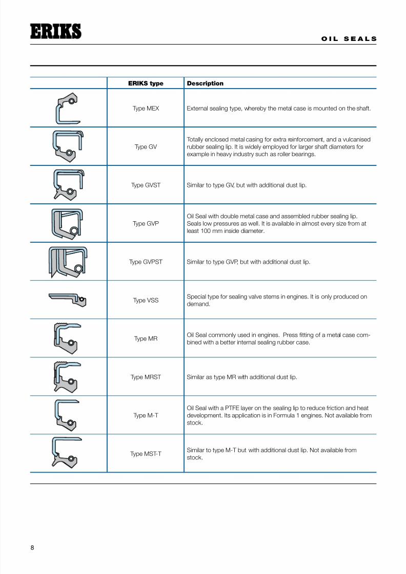
ERIKS type Description
Type MEX External sealing type, whereby the metal case is mounted on the shaft.
Type GV
Totally enclosed metal casing for extra reinforcement, and a vulcanised
rubber sealing lip. It is widely employed for larger shaft diameters for
example in heavy industry such as roller bearings.
Type GVST Similar to type GV, but with additional dust lip.
Type GVP
Oil Seal with double metal case and assembled rubber sealing lip.
Seals low pressures as well. It is available in almost every size from at
least 100 mm inside diameter.
Type GVPST Similar to type GVP, but with additional dust lip.
Type VSS
Special type for sealing valve stems in engines. It is only produced on
demand.
Type MROil Seal commonly used in engines. Press fitting of a metal case com-
bined with a better internal sealing rubber case.
Type MRST Similar as type MR with additional dust lip.
Type M-T
Oil Seal with a PTFE layer on the sealing lip to reduce friction and heat
development. Its application is in Formula 1 engines. Not available from
stock.
Type MST-T Similar to type M-T but with additional dust lip. Not available from
stock.
7/26/2019 oilseals.pdf
http://slidepdf.com/reader/full/oilsealspdf 11/28
O I L S E A L S
9
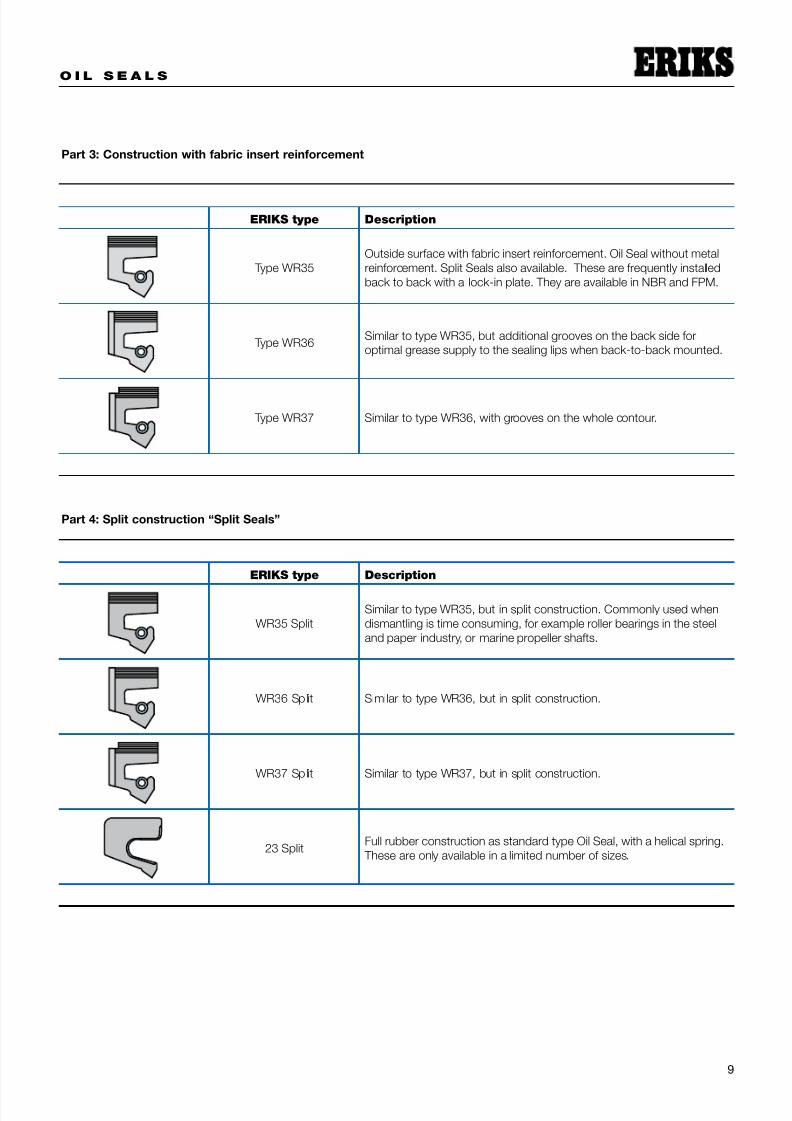
Part 3: Construction with fabric insert reinforcement
ERIKS type Description
Type WR35
Outside surface with fabric insert reinforcement. Oil Seal without metal
reinforcement. Split Seals also available. These are frequently installed
back to back with a lock-in plate. They are available in NBR and FPM.
Type WR36Similar to type WR35, but additional grooves on the back side for
optimal grease supply to the sealing lips when back-to-back mounted.
Type WR37 Similar to type WR36, with grooves on the whole contour.
Part 4: Split construction “Split Seals”
ERIKS type Description
WR35 Split
Similar to type WR35, but in split construction. Commonly used when
dismantling is time consuming, for example roller bearings in the steel
and paper industry, or marine propeller shafts.
WR36 Split Similar to type WR36, but in split construction.
WR37 Split Similar to type WR37, but in split construction.
23 SplitFull rubber construction as standard type Oil Seal, with a helical spring.
These are only available in a limited number of sizes.
7/26/2019 oilseals.pdf
http://slidepdf.com/reader/full/oilsealspdf 12/28
O I L S E A L S
10
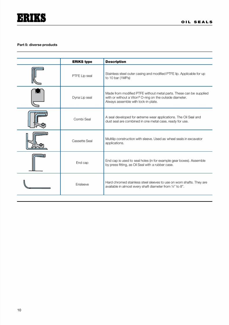
Part 5: diverse products
ERIKS type Description
PTFE Lip sealStainless steel outer casing and modified PTFE lip. Applicable for up
to 10 bar (1MPa)
Dyna Lip seal
Made from modified PTFE without metal parts. These can be supplied
with or without a Viton® O-ring on the outside diameter.
Always assemble with lock-in plate.
Combi Seal A seal developed for extreme wear applications. The Oil Seal and
dust seal are combined in one metal case, ready for use.
Cassette SealMultilip construction with sleeve. Used as wheel seals in excavator
applications.
End capEnd cap is used to seal holes (in for example gear boxes). Assemble
by press fitting, as Oil Seal with a rubber case.
ErisleeveHard chromed stainless steel sleeves to use on worn shafts. They are
available in almost every shaft diameter from ½” to 8”.

7/26/2019 oilseals.pdf
http://slidepdf.com/reader/full/oilsealspdf 13/28

7/26/2019 oilseals.pdf
http://slidepdf.com/reader/full/oilsealspdf 14/28
7/26/2019 oilseals.pdf
http://slidepdf.com/reader/full/oilsealspdf 15/28
O I L S E A L S
13
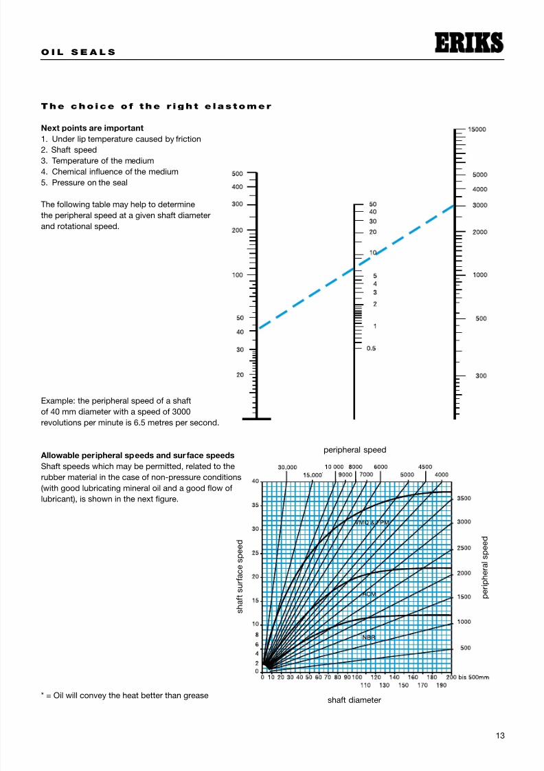
The cho ice o f the r igh t e las tomer
Next points are important
1. Under lip temperature caused by friction
2. Shaft speed
3. Temperature of the medium
4. Chemical influence of the medium
5. Pressure on the seal
The following table may help to determine
the peripheral speed at a given shaft diameter
and rotational speed.
Example: the peripheral speed of a shaft
of 40 mm diameter with a speed of 3000
revolutions per minute is 6.5 metres per second.
Allowable peripheral speeds and surface speeds
Shaft speeds which may be permitted, related to the
rubber material in the case of non-pressure conditions
(with good lubricating mineral oil and a good flow of
lubricant), is shown in the next figure.
* = Oil will convey the heat better than grease
peripheral speed
p e r i p h e r a l s p e e d
s h a f t s u r f a c e s p e e d
shaft diameter

7/26/2019 oilseals.pdf
http://slidepdf.com/reader/full/oilsealspdf 16/28
O I L S E A L S
14
6 . Sha f t mater ia l s , to le rances o f sea ls and hous ing
The housing of the Oil Seal
The size of the housing where the Oil Seal has to be pressed
in has to meet certain requirements. The housing has to
be rather smooth (finely machined). Nominal tolerances
according to ISO H8.
To simplify the assembly, it is recommended that the housing
is lubricated. The housing should have a finish of ca. Ra =
6µm. Oil Seals with a rubber case cannot rust, in contrast to
Oil Seals with metal cases. Moreover, Oil Seals with a rubber
case can seal a lightly damaged housing much better than
metal cased Oils Seals.
To simplify the correct assembly of the Oil Seal, it is
recommended that the housing has a 30° chamfer on the
front side for a minimum length of 1mm. The Oil Seal, when
mounted, has to fall within the limits of this chamfer. For the
assembly depth, there is a tolerance of -0/0,4mm. The Oil
Seals have an interference fit in the housing, which provides
a good press fit, preventing any leakage.
Roughness tolerance of the passing
Shaft Ra ≤ 0,6 µm h11
Housing Ra ≤ 6 µm H 8
Excessive and permitted ovality on the outside diameter (data according to DIN 3760)
Outside Diameter
oil seal (D)
Press fit Permitted ovality
(for all types)R M GV
< 50 mm +0,30/+0,15 +0,20/+0,10 +0,20/+0,10 0,25
50 - 80 mm +0,35/+0,20 +0,23/+0,13 +0,23/+0,13 0,35
80 - 120 mm +0,35/+0,20 +0,25/+0,15 +0,25/+0,15 0,5
120 - 180 mm +0,45/+0,25 +0,28/+0,18 +0,28/+0,18 0,65
180 - 300 mm +0,45/+0,25 +0,30/+0,20 +0,30/+0,20 0,8
300 - 500 mm +0,55/+0,30 +0,35/+0,23 +0,35/+0,23 1
The outside diameter should be measured in at least two places, with an angle of 90° between each measurement.
The mean of both measurements is determined, where the permitted ovality may not be exceeded.

7/26/2019 oilseals.pdf
http://slidepdf.com/reader/full/oilsealspdf 17/28
O I L S E A L S
15
7. Eccent r ic i t y and sha f t osc i l l a t ion
Eccentricity
It is obvious that the centre lines of the housing, Oil Seal and
shaft have to coincide as much as possible. The sealing
element of the Oil Seal will only tolerate a minimum deviation.
The maximum permitted eccentricity is dependent on the
size of the shaft and the type of Oil Seal. In this case, we
assume static eccentricity, and no shaft runout.
ERIKS has special types of Oil Seals, which are suitable
for applications with large shaft eccentricity and runout.
Information on all the possibilities is available.
Shaft oscillation
When shaft runout is present, seals with a loose garter spring
are preferred to seals with an encapsulated spring. The
runout should remain within the limits. “A” represents the
difference between the centre line of the housing bore and
the centre line of the shaft in the region of the seal line. The
two centre lines do not run parallel. The permitted maximum
value of A depends on the rotational speed, the dimensions
of the shaft and the Oil Seal.
shaft velocity
M V Q
N B R , A C M , F P M
s h a f t e c c e n t r i c i t y i n m m
shaft diameter till 500 mm
s h a f t r u n o u t ( m m )
Above diagramm shows the maximum allowable excentricity Above diagramm shows the maximum allowable shaft run out
centerline shaft
centerline bore
7/26/2019 oilseals.pdf
http://slidepdf.com/reader/full/oilsealspdf 18/28
O I L S E A L S
16
8 . Sha f t mater ia l s and to le rances
Material
The rubber material of the Oil Seal is much softer than the
shaft, but due to friction between the shaft and the seal, it
is possible for wear to occur on the contact surface of the
shaft. The degree of wear depends on the structure of the
shaft material. In general, the metal from which the shaft is
made should have a homogeneous fine granulous structure
and must have a minimum surface hardness of HRc 45. If
the lubrication is doubtful, the medium is contaminated, dirt
can enter from the outside and the speed of the shaft is more
than 4 m/sec, the hardness of the shaft should be a minimum
of HRc 55. In general, shafts of carbon steel or stainless steelare most suitable. Surface hardening is recommended. In the
case of hard chromed shafts, the uniformity of the chrome
plating has to meet very high requirements. In practice, such
surfaces do not meet these optimum requirements. Coated
shafts, for example with chrome oxide (ceramics) have to
be carefully machined. The coating should not have pores
larger than 0,05 mm. This is also the case for the surface of
cast iron with a perlitic structure. In some cases, non-ferrous
metals such as brass MS 58H are used. Ceramic sleeves and
Erisleeves are very useful as too. Erisleeves are used in both
original equipment assembly and repair.
Comment: Plastics are unsuitable due to their poor thermal
conductivity. Because of this, underlip heat generation
cannot be readily conducted away, which is not desirable.
Requirements of the shaft
Even more important than a correct interference fit of the
Oil Seal is a perfectly smooth shaft in the region of the seal,
particularly if shaft surface speed is high and the medium
to be sealed is under a certain amount of excess pressure.
The surface roughness of the shaft depends on the average
profile depth Ra of the tool marks caused by the machining
process. Oil Seals made of PTFE require, independent of the
surface speed, a surface roughness of between 0,1 to 0,2µm,
because PTFE has less wear resistance than rubber seals.
For normal circumstances, the shaft in the region of the sealmust have a surface roughness of approximately:
To summarize, the surface of the shaft in the region of
the seal should not have noticeable machining marks.
For pivoting shafts and other difficult or critical sealing
applications, it is recommended that Oil Seals with a helical
groove hydrodynamic pattern, which has a pumping effect,
be used. When grinding and polishing, an axial movement of
the grindstone along the shaft must be avoided in order to
prevent machine lay.
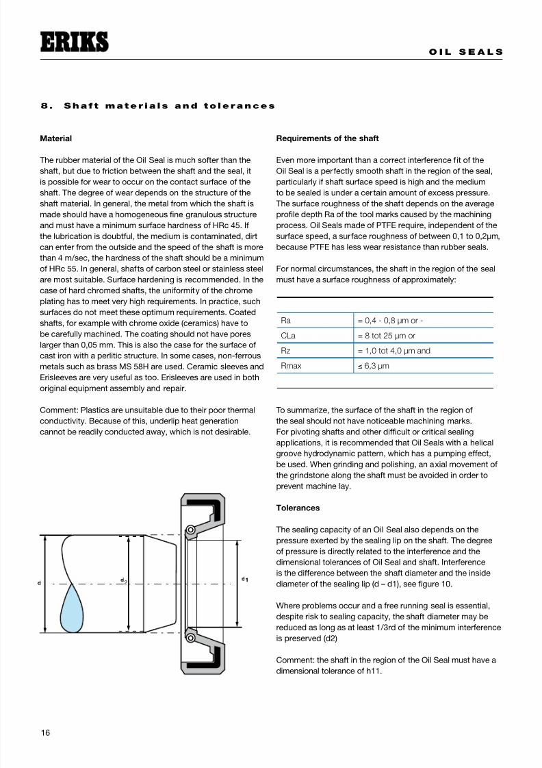
Tolerances
The sealing capacity of an Oil Seal also depends on the
pressure exerted by the sealing lip on the shaft. The degree
of pressure is directly related to the interference and the
dimensional tolerances of Oil Seal and shaft. Interference
is the difference between the shaft diameter and the inside
diameter of the sealing lip (d – d1), see figure 10.
Where problems occur and a free running seal is essential,
despite risk to sealing capacity, the shaft diameter may be
reduced as long as at least 1/3rd of the minimum interference
is preserved (d2)
Comment: the shaft in the region of the Oil Seal must have a
dimensional tolerance of h11.
Ra = 0,4 - 0,8 µm or -
CLa = 8 tot 25 µm or
Rz = 1,0 tot 4,0 µm and
Rmax ≤ 6,3 µm
2

7/26/2019 oilseals.pdf
http://slidepdf.com/reader/full/oilsealspdf 19/28
O I L S E A L S
17
9. Lubr ic at i on
Oil seals for rotating or reciprocating shafts require a certain
degree of lubrication of the moving surfaces.
Oil Seals must never run dry
When seals are adjacent to bearings, the bearing lubricant
will generally provide sufficient lubrication for the seal.
Sealing water as well, most of the time there is enough
lubrication. However, in isolated locations or applications
involving non-lubricating medium, provision should be made
for lubricant to reach the seal. In such case, dual seals
frequently provide an answer as the space between the
sealing edges can be pre-packed with grease thus allowinga considerable period of operation without further attention.
In such instances, the Oil Seals should be mounted in such
a way that no pressure build-up can occur when adding the
grease.
The presence of lubrication is important, not only during
operation, but during assembly as well. Never assemble
an Oil Seal dry. Both the shaft and the Oil Seal have to be
lubricated with oil or grease in advance. This eases the
assembly and ensures lubrication from the beginning.
If Oil Seals with fixed dust lips are being used, the space
between the sealing lip and the dust lip may also be filledentirely with grease. The medium to be sealed will dissipate
the heat developed.
Friction losses
Because the sealing principle of Oil Seals relies on the friction
between the sealing lip and shaft with a minimal fluid film,
friction losses are inevitable. For a given shaft diameter and
a given speed of rotation, the friction coefficient depends on
the friction of the Oil Seal with respect to the shaft.
Determining factors are:
the characteristics of the Oil Seal and the shaft materials•
the surface roughness of the shaft•
the presence and the characteristics of the lubricating film•
the pressure of the medium to be sealed•
the degree of interference of the sealing lip•
the operating temperature•
It is diff icult to measure precise values. However, the graph
below gives useful information concerning friction losses
of standard Oil Seals used in standard quality oil SAE-30
at 100°C on a correctly prepared shaft, after a short time of
running in.
The graph shows the relationship between the power loss,
shaft diameter and shaft speed.
grease
grease
s h a f t d i a m e t e r
revolutions per minute rpm
l o s s o f p o w e r h p
7/26/2019 oilseals.pdf
http://slidepdf.com/reader/full/oilsealspdf 20/28
O I L S E A L S
18
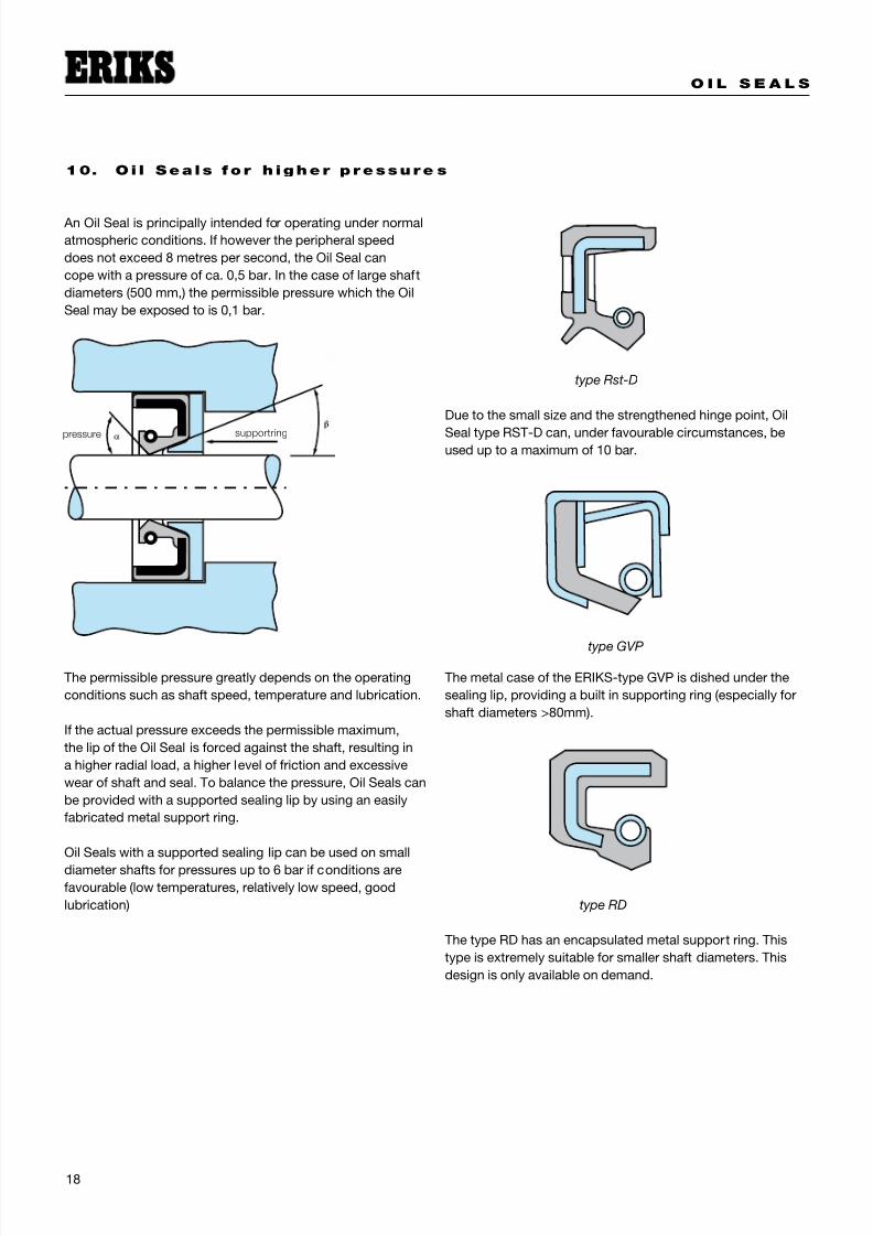
10. O i l Sea ls f o r h igher p ressure s
An Oil Seal is principally intended for operating under normal
atmospheric conditions. If however the peripheral speed
does not exceed 8 metres per second, the Oil Seal can
cope with a pressure of ca. 0,5 bar. In the case of large shaft
diameters (500 mm,) the permissible pressure which the Oil
Seal may be exposed to is 0,1 bar.
The permissible pressure greatly depends on the operating
conditions such as shaft speed, temperature and lubrication.
If the actual pressure exceeds the permissible maximum,
the lip of the Oil Seal is forced against the shaft, resulting in
a higher radial load, a higher level of friction and excessive
wear of shaft and seal. To balance the pressure, Oil Seals can
be provided with a supported sealing lip by using an easily
fabricated metal support ring.
Oil Seals with a supported sealing lip can be used on small
diameter shafts for pressures up to 6 bar if conditions are
favourable (low temperatures, relatively low speed, good
lubrication)
Due to the small size and the strengthened hinge point, Oil
Seal type RST-D can, under favourable circumstances, beused up to a maximum of 10 bar.
The metal case of the ERIKS-type GVP is dished under the
sealing lip, providing a built in supporting ring (especially for
shaft diameters >80mm).
The type RD has an encapsulated metal support ring. This
type is extremely suitable for smaller shaft diameters. This
design is only available on demand.
type Rst-D
type GVP
type RD
supportringpressure

7/26/2019 oilseals.pdf
http://slidepdf.com/reader/full/oilsealspdf 21/28
O I L S E A L S
19
11. Sp l i t O i l Sea l s
Split Oil Seals are most frequently used in situations were
dismantling is too difficult, such as in the steel industry,
paper industry, heavy excavators or marine propellers shafts.
ERIKS has a wide variety of Split Oil Seals
ERIKS Split Seals are available in both NBR and FPM metric
and inch sizes.
Split Seals cannot be mounted like the standard types (DIN),
by means of press fitting in the housing. Split Seals must be
locked by means of a lock-in plate (see figure).
Type R23 split
The most common type is ERIKS type R23 split. This type
has a full rubber profile with an encapsulated wave spring.
This design is available in both metric and inch sizes in NBR
and FPM.
Recommended profile dimensions
ERIKS Split Seals R23-split are supplied with an oversize en
are flush mounted. As a result, ERIKS Split Seals type R23-
split, in non-pressure applications, seal reliably on the seam.
In very critical situations we recommend that you lime the
ends with a lime out our Sicomet program.
ERIKS R23-Split Seals are easy to cut and can be tailored to
suit the required size by cutting from a bigger ring.
WR35 Split:
Insert fabric reinforced. Commonly
used when dismantling is very time
consuming, for example roller bear-
ings in the steel and paper industry,or marine propeller shafts.
WR36 Split:
Similar to type WR35 Split, but with
more grooves for optimal grease
supply to the sealing lips when
back-to-back mounted.
WR37 Split:
Similar to type WR36 Split, but with
grooves on the whole contour.
23 Split:
Full rubber design as standard typeOil Seal, but with a stainless steel
wave spring. It is available in NBR
and FPM.
VR-Split:
Full rubber design as standard type
Oil Seal, but with a stainless steel
garter spring. It is only available in a
limited number of dimensions.
range
Shaft
diameter
Radial
height Axial height Size
(h1) mm h w c (max.)
75 - 250 mm 12,5 mm 12,5 mm 7,5 mm
120 - 350
mm15 mm 15 mm 10 mm
250 - 500
mm20 mm 20 mm 10 mm
500 - 1500
mm25 mm 20 mm 10 mm
h
c
block-in plate

7/26/2019 oilseals.pdf
http://slidepdf.com/reader/full/oilsealspdf 22/28
O I L S E A L S
20
Type with insert fabric reinforcement
All the insert fabric reinforcement Oil Seals (general, and Split
Seals) are supplied with a height size which is 0,5 to 0,6 mm
larger than dimension b. The lock-in plate re-forms the Oil
Seal diametrically which ensures reliable sealing on the shaftand the housing in service.
ERIKS insert fabric reinforcement Oil Seals type WR 35 split,
type WR 36 split and type WR 37 split are moulded and are
provided with a seam. If the desired size is not available in
the list, please contact us. ERIKS has more sizes than listed.
Please allow a delivery time of 8 to 16 weeks.
When assembling these Split Seals, it is necessary to remove
the garter spring from the sealing lip and then re-fit it when
the seal has been mounted over the shaft.
Comment: Please take into account that with this type of
Split Seal, the seam, when mounted on the shaft, must be at
the top (12 O’clock). Moreover, the medium to be sealed must
not be above the centre line of the shaft.
Type VR split
For the assembly of these Split Seals, it is necessary to
remove the garter spring from the sealing lip and then re-fit it
when the seal has been mounted on the shaft.
Comment: Please take into account that with this type of
Split Seal, the seam, when mounted on the shaft, must be at
the top (12 O’clock). Moreover, the medium to be sealed must
not be placed above the centre line of the shaft.
ERIKS Split Seals type VR-Split are manufactured completely
from rubber, where the outside of the Oil Seal has a hardness
of 90° Shore “A” and the inside body and the sealing lip has a
hardness of is 70° Shore “A”. This design as well the sealing
lip is centred by a helical spring.
ERIKS Split Seals type VR-Split are available in a limited
number of sizes. We recommend that you to inform us of your
requirements before you choose one of these types of seals.

7/26/2019 oilseals.pdf
http://slidepdf.com/reader/full/oilsealspdf 23/28
O I L S E A L S
21
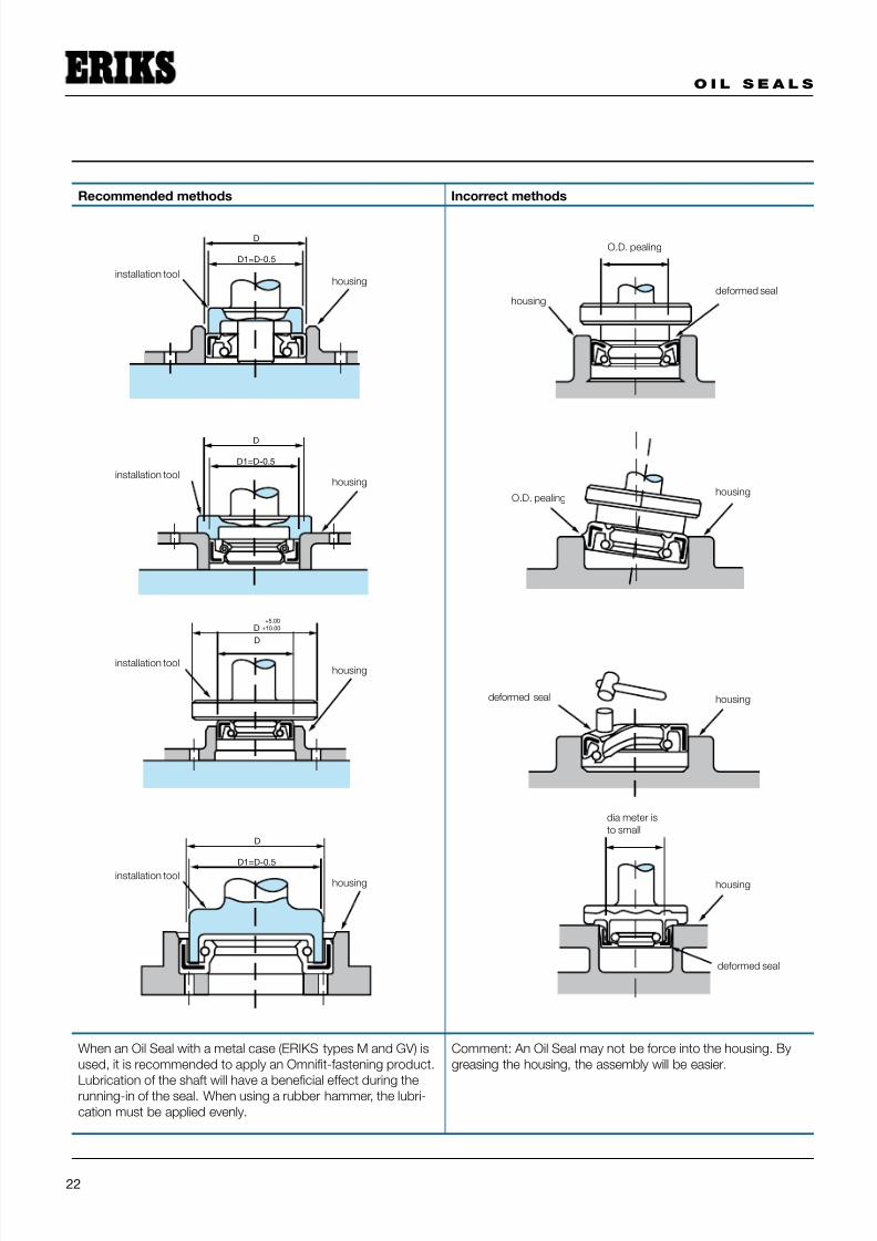
12 . Assembly o f the O i l Sea l
That the assembly of oil seals has to be done with a lot of
care speaks for itself. The Oil Seal, the shaft and the housing
have to be clean. Dirt, which may enter the system during
assembly between the sealing lip and the shaft, can cause
leakage.
Because the inside diameter of the Oil Seal during assembly
has to be stretched, is it necessary that the shaft has a
chamfer. The angle for the chamfer is approximately 30° to
50°.
When a spline on the shaft is present, a mounting sleeve
must be used to protect the sealing lip. The housing chamfer
must have a length of at least 1 mm. The sides have to be
obtused.
During assembly, it is essential to prevent damage to the
oil seal. If the Oil Seal must pass over irregularities such as
screw-thread or splines, the shaft must be covered with oil
soaked paper, tape, or with a protective socket or mounting
sleeve made of metal or plastic.
The pressing of the Oil Seal into the housing has to be done
evenly. Preferably, an adapted fitting tool should be used,
so that the pressure is transferred through the part of the Oil
Seal which is reinforced with metal.
In order for the Oil Seal operate correctly; the sealing lip
material has to be compatible with the medium to be sealed.
To improve the sliding over the shaft, it is required that both
the shaft and the sealing lip are lubricated with oil or grease.
Oil Seals with a leather sealing lip have to be oil-soaked in
advance.
to round the edge
installationtoolgland
7/26/2019 oilseals.pdf
http://slidepdf.com/reader/full/oilsealspdf 24/28

7/26/2019 oilseals.pdf
http://slidepdf.com/reader/full/oilsealspdf 25/28
O I L S E A L S
23
13. Trou blesh oot ing
There are two potential leak paths on an oil seal, i.e. between
the outside diameter of the Oil Seal and the housing (static),
and between the sealing lip and the shaft (dynamic).
In the table below the causes are listed, with a few
recommendations to prevent these problems.
Symptoms Cause Remedy
Oil Seal rotates with the shaftOutside diameter is smaller than the
housing diameter
Replace the Oil Seal, choose the right
size
Oil Seal is moving in an axial direction on
the shaft
Outside diameter is smaller than the
housing diameter Replace the Oil Seal, choose the right
sizeDue to excess pressure the Oil Seal is
moving axially
The mounted Oil Seal is deformed Inside diameter of the Oil Seal is too small Control the size of the shaft
The case of the Oil Seal is deformed Wrong installation tools has been used Use the right tools
Damaged surface of the Oil Seal
The finishing has not been executed
properly
Control the roughness of the housing and
the presence of a chamfer
Dirt at the in- our outside of the housing Clean all parts before assembly
Damaged sealing lip
Insufficient lubrication Lubricate sufficiently
Construction limits the transport of the
lubrication to the sealing lip
Change the construction so that sufficient
lubrication reaches the sealing lip
Partly damaged sealing lipOil Seal not placed concentric with
regards to the housingCentre the seal, use the right tools
Sealing lip has hardened, is worn out and
is torn
To high temperature, shaft speed,
pressure
Choose the right rubber compound and
type of Oil Seal
Insufficient lubrication Lubricate sufficiently
Swollen sealing lip Incorrect rubber compound Choose the correct material
Scraped sealing lipRoughness of the shaft is incorrect Control roughness
Incorrect tools used during assembly Choose correct assembly tool
Collapsed sealing lipIncorrect assembly Lubricate before the assembly
Too high pressure Choose an Oil Seal for high pressures
The flexible part is torn Too high pressure
Choose an Oil Seal for high pressuresPressure directed at the flexible part
Garter spring out the groove
Chamfer does not have the correct angleUse a mounting sleeve, or make a
chamfer on the shaft
Incorrect assembly Take care during the assembly
Grooves not deep enoughChoose another design, or use a spring
with a smaller diameter

7/26/2019 oilseals.pdf
http://slidepdf.com/reader/full/oilsealspdf 26/28
O I L S E A L S
24
inches 0 1 2 3 4 5 6 7 8 9
0 - 25.400 50.800 76.200 101.600 127.000 152.400 177.800 203.200 228.600
0.397 25.797 51.197 76.597 101.997 127.397 152.797 178.197 203.597 228.997
0.794 26.194 51.594 76.994 102.394 127.794 153.194 178.594 203.994 229.394
1.191 26.591 51.991 77.391 102.791 128.191 153.591 178.991 204.391 229.791
1.588 26.988 52.388 77.788 103.188 128.588 153.988 179.388 204.788 230.188
1.984 27.384 52.784 78.184 103.584 128.984 154.384 179.784 205.184 230.584
2.381 27.781 53.181 78.581 103.981 129.381 154.781 180.181 205.581 230.981
2.778 28.178 53.578 78.978 104.376 129.778 155.178 180.578 205.978 231.778
3.175 28.575 53.975 79.375 104.775 130.175 155.575 180.975 206.375 231.375
3.572 28.972 54.372 79.772 105.172 130.572 155.972 181.372 206.772 232.172
3.969 29.369 54.769 80.169 105.569 130.969 156.369 181.769 207.169 232.569
4.366 29.766 55.166 80.566 105.966 131.366 156.766 182.166 207.566 232.966
4.763 30.163 55.563 80.963 106.363 131.763 157.163 182.563 207.963 233.363
5.159 30.559 55.959 81.359 106.759 132.159 157.559 182.959 208.359 233.759
5.556 30.956 56.356 81.756 107.156 132.556 157.956 183.356 208.756 234.1565.953 31.353 56.753 82.153 107.553 132.953 158.353 183.753 209.153 234.553
6.350 31.750 57.150 82.550 107.950 133.350 158.750 184.150 209.550 234.950
6.747 32.147 57.547 82.947 108.347 133.747 159.147 184.547 209.947 235.347
7.144 32.544 57.944 83.344 108.744 134.144 159.544 184.944 210.344 235.744
7.541 32.941 58.341 83.741 109.141 134.541 159.941 185.341 210.741 236.141
7.938 33.338 58.738 84.138 109.538 134.938 160.338 185.738 211.138 236.538
8.334 33.734 59.134 84.534 109.934 135.334 160.734 186.134 211.534 236.934
8.731 34.131 59.531 84.931 110.331 135.731 161.131 186.531 211.931 237.331
9.128 34.528 59.928 85.328 110.728 136.128 161.528 186.928 212.328 237.728
9.525 34.925 60.325 85.725 111.125 136.525 161.925 187.325 212.725 238.125
9.922 35.322 60.722 86.122 111.522 136.922 162.322 187.722 213.122 238.522
10.319 35.719 61.119 86.519 111.919 137.319 162.719 188.119 213.519 238.919
10.716 36.116 61.516 86.916 112.316 137.716 163.116 188.516 213.916 239.316
11.113 36.513 61.913 87.313 112.713 138.113 163.513 188.913 214.313 239.713
11.509 36.909 62.309 87.709 113.109 138.509 163.909 189.309 214.709 240.10911.906 37.306 62.706 88.106 113.506 138.906 164.306 189.706 215.106 240.506
12.303 37.703 63.103 88.503 113.903 139.303 164.703 190.103 215.503 240.903
12.700 38.100 63.500 88.900 114.300 139.700 165.100 190.500 215.900 241.300
13.097 38.497 63.897 89.297 114.697 140.097 165.497 190.897 216.297 241.697
13.494 38.894 64.294 89.694 115.094 140.494 165.894 191.294 216.694 242.094
13.891 39.291 64.691 90.091 115.491 140.891 166.291 191.691 217.091 242.491
14.288 39.688 65.088 90.488 115.888 141.288 166.688 192.088 217.488 242.888
14.684 40.084 65.484 90.884 116.284 141.684 167.084 192.484 217.884 243.284
15.081 40.481 65.881 91.281 116.681 142.081 167A81 192.881 218.281 243.681
15.478 40.878 66.278 91.678 117.078 142.478 167.878 193.278 218.678 244.078
15.875 41.275 66.675 92.075 117.475 142.875 168.275 193.675 219.075 244.475
16.272 41.672 67.072 92.472 117.872 143.272 168.672 194.072 219472 244.872
16.669 42.069 67.469 92.869 118.269 143.669 169.069 194.469 219869 245.269
17.066 42.466 67.866 93.266 118.666 144.066 169.466 194.866 220.266 245.666
17.463 42.863 68.263 93.663 119.063 144.463 169.863 195.263 220.663 246.06317.859 43.259 68.659 94.059 119.459 144.859 170.259 195.659 221.059 246.459
18.256 43.656 69.056 94.456 119.856 145.256 170.656 196.056 221.456 246.856
18.653 44.053 69.453 94.853 120.253 145.653 171.053 196.453 221.853 247.253
19.050 44.450 69.850 95.250 120.650 146.050 171.450 196.850 222.250 247.650
19.447 44.847 70.247 95.647 121.047 146.447 171.847 197.247 222.647 248.047
19.844 45.244 70.644 96.044 121.444 146.844 172.244 197.644 223.044 248.444
20.241 45.641 71.041 96.441 121.841 147.241 172.641 198.041 223.441 248.841
20.638 46.038 71.438 96.838 122.238 147.638 173.038 198.438 223.838 249.238
21.034 46.434 71.834 97.234 122.634 148.034 173.434 198.834 224.234 249.634
21.431 46.831 72.231 97.631 123.031 148.431 173.831 199.231 224.631 250.031
21.828 47.228 72.628 98.028 123.428 148.828 174.228 199.628 225.028 250.428
22.225 47.625 73.025 98.425 123.825 149.225 174.625 200.025 225.425 250.825
22.622 48.022 73.422 98.822 124.222 149.622 175.022 200.422 225.822 251.222
23.019 48.419 73.819 99.219 124.619 150.019 175.419 200.819 226.219 251.619
23.416 48.816 74.216 99.616 125.016 150.416 175.816 201.216 226.616 252.01623.813 49.213 74.613 100.013 125.413 150.813 176.213 201.613 227.013 252.413
24.209 49.609 75.009 100.409 125.809 151.209 176.609 202.009 227.409 252.809
24.606 50.006 75.406 100.806 126.206 151.606 177.006 202.406 227.806 253.206
25.003 50.403 75.803 101.203 126.603 152.003 177.403 202.803 228.203 253.603
132
116
332
18
532
316
7
32
14
932
516
1132
38
1332
716
1532
12
1732
916
1932
18
2132
11
16
2332
34
2532
1316
2732
78
2932
1516
3132
164
364
564
764
964
1164
1364
1564
1764
1964
2164
2364
2564
2764
2964
3164
3364
3564
3764
3964
4164
4364
4564
4764
4964
5164
5364
5564
5764
5964
6164
6364
14 . Convers ion tab le inch / mm

7/26/2019 oilseals.pdf
http://slidepdf.com/reader/full/oilsealspdf 27/28
O I L S E A L S
25
d2
b
d
95
100
105
110
115
120
125
130
135
140
145
150160
170
180
190
200
210
220
230
240
250
260
280
300
320
340
360
380
400
420
440
460
480
500
6
7
8
9
10
12
14
15
16
18
20
22
25
28
30
32
16
22
22
22
24
22
22
25
26
22
25
30
24
30
26
30
35
30
35
30
35
30
35
40
35
40
47
35
40
47
52
40
47
52
40
42
47
52
45
47
52
45
47
52
7
7
7
7
7
7
7
7
7
7
7
7
7
7
7
7
8
d d2
b
± 0,2
35
38
40
42
45
48
50
55
60
65
70
75
80
85
90
47
50
52
55
47
50
52
55
55
62
55
62
52
55
62
5255
62
55
62
60
62
65
62
65
68
72
70
72
80
75
80
85
85
90
90
95
95
100
100
110
110
120
110
120
7
8
7
8
7
8
8
8
8
8
8
8
10
10
10
10
12
12
d d2
b
± 0,2
120
125
120
125
26
130
130
140
140
150
150
160
170
170
175
180190
200
210
220
230
240
250
260
270
280
300
320
340
360
380
400
420
440
460
480
500
520
540
12
12
12
12
12
12
12
12
12
15
15
15
15
15
20
20
20
20
d d2
b
± 0,2
15 . Tab le o f D IN d ime ns ions
shaft diameter shaft diameter shaft diameter

7/26/2019 oilseals.pdf
http://slidepdf.com/reader/full/oilsealspdf 28/28
ERIKS Servicecenters
AlkmaarSaffierstraat 3NL-1812 RM AlkmaarT +31 72 514 17 17F +31 72 514 16 [email protected]
AlmeloPlesmanweg 12NL-7602 PE AlmeloT +31 546 87 30 70F +31 546 87 32 [email protected]
AmsterdamDynamostraat 46-48NL-1014 BK Amsterdam-Westpoort
T +31 20 448 96 10F +31 20 613 77 [email protected]
ArnhemPieter Calandweg 46NL-6827 BK ArnhemT +31 26 362 92 44F +31 26 361 00 [email protected]
Den HaagNeckar 2NL-2491 BD Den HaagT +31 70 381 84 84F +31 70 381 84 [email protected]
EindhovenDe Witbogt 22NL-5652 AG EindhovenT +31 40 291 19 00F +31 40 291 19 [email protected]
HengeloHassinkweg 16NL-7556 BV Hengelo
T +31 74 291 57 57F +31 74 291 59 [email protected]
LeekZernikelaan 10NL-9351 VA LeekT +31 594 51 70 00F +31 594 51 41 [email protected]
Leeuwarden James Wattstraat 18NL-8912 AS LeeuwardenT +31 58 215 05 87F +31 58 215 85 [email protected]
MaastrichtAmerikalaan 28NL-6199 AE Maastricht-AirportT +31 43 604 91 80F +31 43 363 87 [email protected]
RoermondAda Byronweg 11NL-6045 GM Roermond
T +31 475 37 22 70F +31 475 37 23 [email protected]
RotterdamCaïrostraat 80NL-3047 BC RotterdamT +31 10 245 50 55F +31 10 262 00 [email protected]
Rotterdam-BotlekShannonweg 33, Haven 5079NL-3197 LG Botlek-RotterdamT +31 10 231 34 00F +31 10 296 73 [email protected]
Tilburg Ellen Pankhurststraat 9NL-5032 MD TilburgT +31 13 571 45 61F +31 13 570 06 [email protected]
ZwolleAmpèrestraat 27NL-8013 PT Zwolle
T +31 38 467 29 20F +31 38 467 29 [email protected]
ERIKS bv T +31 72 514 15 14
Headoffice
ERIKS bvToermalijnstraat 51812 RL AlkmaarTel. +31 72 514 15 14Fax +31 72 515 56 [email protected]
8 4 7 0 3 3
© Mi t s v o o r z i e nv a n d ui d e l i j k e b r o nv e r m e l d i n g i s o v e r n a m e ui t d e z e p u b l i c a t i e
t o e g e s t a a n.A l l e r e c h t e nw o r d e n d o o r E R I K S n a d r uk k e l i
j k v o o r b e h o u d e n.
N o p a r t o f t h i s p u b l i c
a t i o nm a y b e r e pr o d u c e d wi t h o u t c l e a r r e f e r e n c e t o t h e s
o ur c e .A l l r i g h t s e x pr e s s l y r e s e r v e d b y E R I K S .


