OIL SHALE RESEARCH, DEVELOPMENT & … SHALE RESEARCH, DEVELOPMENT & DEMONSTRATION PROJECT PLAN OF...
46
OIL SHALE RESEARCH, DEVELOPMENT & DEMONSTRATION PROJECT PLAN OF OPERATIONS February 15, 2006 Applicant: CHEVRON USA INC. 11111 Wilcrest Houston, Texas 77099 Prepared by: Cordilleran Compliance Services, Inc. 826 21 1/2 Road Grand Junction, CO 81505
Transcript of OIL SHALE RESEARCH, DEVELOPMENT & … SHALE RESEARCH, DEVELOPMENT & DEMONSTRATION PROJECT PLAN OF...

OIL SHALE RESEARCH, DEVELOPMENT & DEMONSTRATION PROJECT
PLAN OF OPERATIONS
February 15, 2006
Applicant:
CHEVRON USA INC. 11111 Wilcrest
Houston, Texas 77099
Prepared by:
Cordilleran Compliance Services, Inc. 826 21 1/2 Road
Grand Junction, CO 81505

Preface This Plan of operations is organized to cover the seven major points as laid out in the Plan of Operations Requirements for Oil Shale Research, Development and Demonstration (R,D&D) Tracts finalized by the BLM on Friday January 27, 2006. Items numbered 1 through 7 below correspond with the required information of said notice. 1) Names, addresses and telephone numbers of those responsible for operations to be
conducted under the approval plan to whom notices and orders are delivered: Lee Parker Chevron U.S.A, Inc. * 11111 S. Wilcrest Houston, TX 77099 Phone: 925-842-1000 (General Switchboard number for Corporation) 281-561-4725 (Direct dial number) 281-561-3160 (Direct Fax number) *Chevron U.S.A. Inc. is a wholly owned subsidiary of Chevron Corporation (formerly ChevronTexaco Corporation)
2) Names and addresses of surface and mineral owners of record:
Bureau of Land Management White River Field Office 73544 Highway 64 Meeker, Colorado 81641
3) A detailed description, and maps where appropriate, of the following: The Geologic/Hydrologic conditions within the lease tract, and an estimate of the quantity and quality of all mineral resources are detailed in section 2.0 of the Plan of Operations. Figures 1 through 11 illustrate the Hydrogeologic units; Lithologies near the proposed lease area; Maps of the Top Parachute Creek Member, the Mahogany Zone, Top Orange Marker of the Garden Gulch Member (these maps include the locations of existing oil and gas wells); The W-E stratigraphic Section A-A; Fischer Assay Data comparison of nearby wells;

Oil Shale resources in the Piceance Basin and overburden cross sections; nahcolite and dawsonite iso-reserves; and Piceance Basin aquifer concentrations.
The location and design of proposed roads, well pads, storage tanks, surface structures/facilities, and power are discussed in the Construction Activities of section 4.0 of the Plan of Operations, and in section 5.0 (Location and Design of Facilities), with a more detailed description and illustrations in the confidential appendix A. The number of employees required during construction and operation, including the amount and types of truck traffic is included within these sections as well, and are also discussed in section 8.0 (Potential Socioeconomic and Transportation Requirements for Construction and Operations. The use of ponds is not anticipated, and pits are mentioned in the Hazardous Materials Management section (4.6) under Wastes Generated from the Drilling Operation.
Access required for the routing of electrical power, natural gas pipelines, water and communication is illustrated in Figure 14.
Methods for containment/disposal of trash/waste material produced are outlined in section 4.0, both in the Storage/disposal of products and Hazardous Materials management sections.
4) The drilling plan is discussed briefly in the Construction Activities section (4.0) of the Plan of Operations. A discussion of specific details of the drilling plan along with figures and illustrations can be found in the confidential appendix. The items of requested information falling under this bullet item are all addressed in detail in the confidential appendix.
5) Discussions of environmental aspects such as water usage, production, storage and disposal, and potential contaminants that may enter any receiving waters are discussed throughout section 4.0. A Stormwater Management Plan is included in Appendix A. Section 4.0 includes descriptions of measures to be taken to prevent fire, soil erosion, pollution of surface and ground waters, air, damage to fish and wildlife or other natural resources, and includes hazards to public health and safety. Mitigation measures are discussed in section 7.0, and include Threatened and Endangered and Sensitive species and Cultural Resources. The methods for monitoring the environmental impacts are explained more thoroughly in the confidential appendix A.
6) Reclamation scheduled and measures taken for reclamation are addressed in sections 5.0 and 6.0 of the Plan of Operations.
7) The method and timing of abandonment are discussed in section 5.0 and 6.0 of the Plan of Operations. Proposed well abandonment procedures are addressed in section 4.0 (Well Abandonment Procedures)
ii

TABLE OF CONTENTS
Table of Contents......................................................................................................................... iii 1.0 Introduction .......................................................................................................................1
1.1 Project Description ........................................................................................................1 1.2 Purpose and Need ........................................................................................................1
2.0 Basin Geology / Mineralogy / Hydrology ...........................................................................2 2.1 Geology.........................................................................................................................2 2.2 Mineralogy.....................................................................................................................5 2.3 Other Mineral Resources ............................................................................................12 2.4 Hydrology .........................................................................................................................13
3.0 Pre-Construction Activities ..............................................................................................17 3.1 Survey and Mapping ...................................................................................................17 3.2 Geophysical Surveys...................................................................................................17
4.0 Construction Activities.....................................................................................................17 4.1 Access.........................................................................................................................17 4.2 Construction Plan........................................................................................................18 4.3 Facility Construction....................................................................................................18 4.4 Clearing and Grading ..................................................................................................18 4.5 Trenching ....................................................................................................................19 4.6 Cleanup.......................................................................................................................19 4.7 Lighting and Security...................................................................................................20 4.8 Location of Proposed Roads.......................................................................................20 4.9 Location of Well / Facility Pads ...................................................................................20 4.10 Power and Natural Gas Lines .....................................................................................21 4.11 Ponds ..........................................................................................................................22 4.12 Offices / Labs .................................................................................................................23 4.13 Monitoring Wells.............................................................................................................23 4.14 Storage Tanks ................................................................................................................23
5.0 Phased Development of Testing Facilities............................................................................24 5.1 Groundwater Program.......................................................................................................28
5.1.1 Groundwater Monitoring ............................................................................................28 5.1.2 Groundwater Monitor Well Construction....................................................................29 5.1.3 Data Management Plan .............................................................................................29
5.2 Surface Wastewater ..........................................................................................................30 5.3 Air Emissions....................................................................................................................31 5.4 Air Quality Monitoring ........................................................................................................32 5.5 Noise Abatement...............................................................................................................32
6.0 Hazardous Materials Management ......................................................................................32 6.1 Solid Waste Management .................................................................................................32 6.1 Waste generated from the drilling operation .....................................................................33 6.3 Spill Prevention Control and Countermeasure (SPCC) Plan.............................................34 6.4 Hazards to public health and safety ..................................................................................34 6.5 Well abandonment procedures .........................................................................................35 6.6 Fire Prevention and Suppression .....................................................................................36
7.0 Final site abandonment and reclamation .............................................................................36 7.1 Revegetation ....................................................................................................................37
8.0 Post-Construction Activities ..................................................................................................38 8.1 Maintenance and Operation ..............................................................................................38
iii

8.2 Abandonment ...................................................................................................................38 9.0 Mitigation Measures..............................................................................................................38
9.1 Noxious Weeds .................................................................................................................38 9.2 Erosion .............................................................................................................................39 9.3 Threatened, Endangered, and Sensitive Species ............................................................39 9.4 Cultural Resources...........................................................................................................39 9.5 Air Quality.........................................................................................................................40 9.6 Potential Socioeconomics and Transportation Requirements for Construction and Operations...............................................................................................................................40
10.0 References.........................................................................................................................41
iv

1.0 INTRODUCTION
1.1 PROJECT DESCRIPTION Chevron U.S.A. Inc. has applied to the Bureau of Land Management (BLM) for a pilot Oil Shale Research, Development and Demonstration (R,D&D) lease, together with any supporting rights-of-way (ROW), located in the Piceance Basin of Northwestern Colorado. The lease tract is described as the northern most 160 acres of Lots 5, 6, 11 and 12, all of which are located within the NE/4 of Section 5, T3S, R97W, 6th Principal Meridian, Rio Blanco County, Colorado.
The project consists of a 10-year lease agreement that would allow for the research, development and demonstration of Chevron’s shale oil recovery technologies, and will focus on the development of an economical, sustainable, and acceptable technology which could result in the eventual commercial development of oil shale as an energy resource. This lease agreement is designed to facilitate demonstration of technologies for shale oil extraction which are then tested on a pilot scale. As the technologies evolve, changes in the program will necessarily need to be made to respond to the developing knowledge base.
1.2 PURPOSE AND NEED The Bureau of Land Management has initiated a demonstration project under which small tracts of land within the Piceance Basin may be leased for oil shale research, development and demonstration, pursuant to BLM's authority to lease Federal lands for oil shale development under section 21 of the Mineral Leasing Act, 30 U.S.C. 241. The United States holds significant oil shale resources, primarily within the Green River Formation in Colorado, Utah and Wyoming. These oil shale resources underlie a total area of 16,000 square miles, which represents the largest known concentration of oil shale in the world. Federal lands comprise roughly 72% of the total surface oil shale acreage and 82% of the oil shale resources in the Green River Formation. For a considerable time, some have believed that oil shale has the potential to be a major source of domestic energy production. BLM has considered the merits of working to promote the development of oil shale resources on public lands. ([Federal Register: June 9, 2005 (Volume 70, Number 110)] [Notices] [Pages 33753-33759]) Chevron understands the need for oil shale research, and is committed to the development of innovative technologies that may significantly enhance the collective knowledge regarding the viability of oil shale development on a commercial scale. The purpose of this project is to develop the technologies to commercially develop oil shale.
1

2.0 BASIN GEOLOGY / MINERALOGY / HYDROLOGY
2.1 GEOLOGY The Piceance Basin is a large asymmetric structural downwarp in northwest Colorado, which covers about 7,100 square miles (Topper et al, 2003). It is bounded on the west by the Douglas Creek Arch, to the southwest by the Uncompahgre Uplift, to the south by Gunnison Uplift, to the east by the Grand Hogback and White River Uplift, and to the north by the Yampa Plateau. The axis of the basin trends NW to SE and the northern and eastern flanks dip more steeply into the basin.
The stratigraphic column for the Piceance Creek Basin is shown in Figure 1 (Cole and Cumella, 2003). The section of main concern for the oil shale leasing program in the vicinity of Chevron’s proposed lease is the Eocene Green River formation, and the formations immediately above and below it. The Uinta Formation overlies the Green River Formation and consists of discontinuous layers of silty sandstone, siltstone, and marlstone deposited in a fluvial (stream bed) environment. The Uinta is exposed at the surface over the proposed lease tract, so that the entire thickness is not present. The contact with the underlying Parachute Creek member of the Green River Formation is transitional and there are intertongues of both lithologies.
The Green River Formation was deposited in a saline or alkaline lake that once covered the Piceance Basin as well as parts of Utah and Wyoming. Because the sediments were deposited in a low energy environment, markers are fairly continuous over large areas. In the Piceance Creek Basin, the Green River Formation is composed of four members, with only two members (Parachute Creek and Garden Gulch) containing oil shale deposits. These two members are of primary interest in the proposed leased tract.
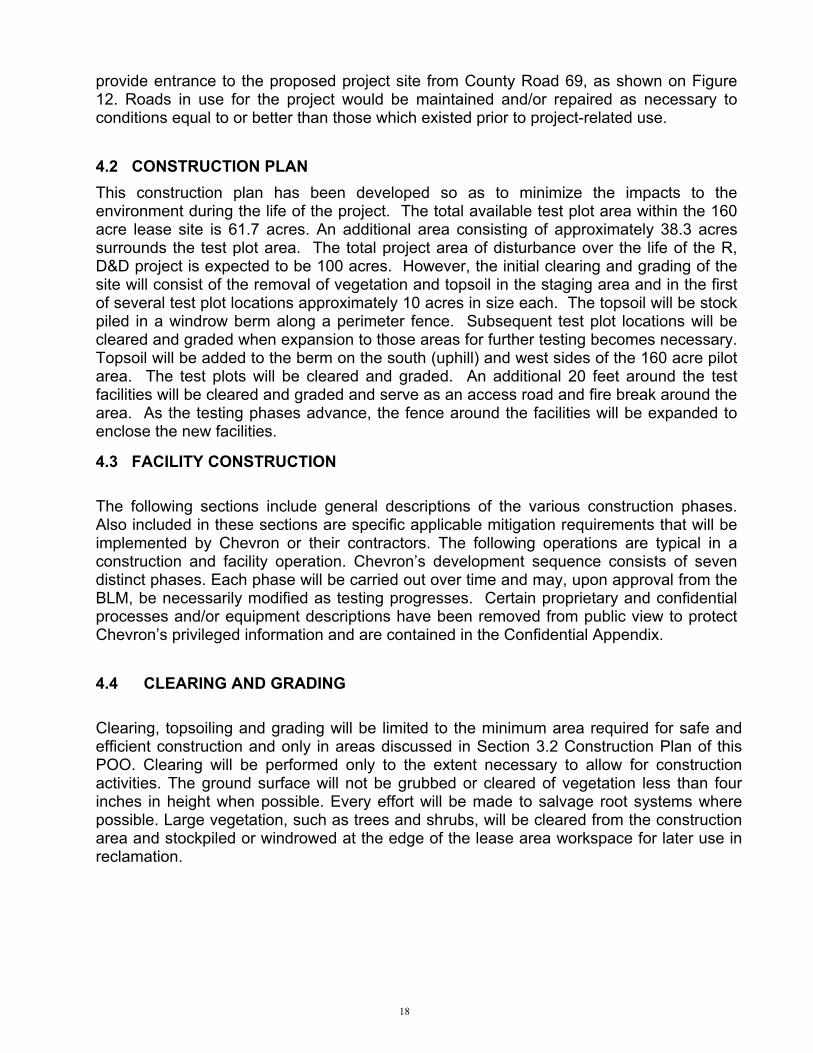
The oil shale is lithologically complex, with marlstone, dolomite, limestone, nahcolite, halite, dawsonite and other minerals. A generally accepted definition of oil shale is a dense, laminated rock which yields oil when heated. Most of the oil shale is in the Parachute Creek member, which has been subdivided into rich and lean zones (R and L, Figure 2), based on modified Fischer assay values. The cut-off between rich and lean was arbitrarily defined as 25 gal/ton (Ziemba, 1974). The Mahogany Zone is the most consistently rich, and areally extensive, of the oil shale sections and was the primary focus of previous surface and subsurface mining and retorting efforts.
2

GENERAL STRATIGRAPHIC COLUMN* GRAND JUNCTION, COLORADO AREA
AGE FORMATION MEMBER THICKNESS (feet)
DOMINANT ROCK TYPE
Grand Mesa <100 Gravel & Till Quaternary Lands End <100 Gravel & Till
Miocene Basalt 170-680 Basalt Miocene Unnamed 0-100 Sandstone & Mudrock
Uinta 700+
Sandstone & Mudrock
Parachute Creek 300-1600 Oil Shale and Marlstone
Garden Gulch 300-700 Mudrock, Limestone & Sandstone
Eocene Green River
Douglas Creek/ Anvil Points 100-300 Sandstone & Shale
Paleocene Wasatch 1350-6300 Sandstone & Mudrock
Williams Fork
1800-2550 Sandstone, Mudrock, Coal
Mes
aver
de
Gro
up
Iles 350-660 Sandstone & Mudrock
Mancos
4000-4500 Mudrock & Silty Sandstone
Upper Cretaceous
Dakota 80-120 Mudrock, Sandstone & Coal
Lower Cretaceous Burro Canyon 100-200 Sandstone & Mudrock
Brushy Basin 200-300 Sandstone & Mudrock Saltwash 100-150 Sandstone & Mudrock Morrison Tidwell 50-120 Sandstone, Mudrock &
Limestone Wanakah 20-40 Mudrock Entrada 150-150 Sandstone Kayenta 50-80 Sandstone & Mudrock
Jurassic
Wingate 250-320 Sandstone Triassic Chinle 80-120 Mudrock & Sandstone
Proterozoic Black Canyon Complex
Schist, gneiss, granite, diorite
*Modified from Cole, R. and Cumella, S. (2003)
Figure 1
3

Lithologies Near Proposed Lease Area, T3S, R97W, Piceance Basin, Colorado
Formation Member Zone Lithology
Uin
ta
Form
atio
n
R-8 A Groove
(L-7) Mahogany
(R-7) B Groove
(L-6) Sandstone, siltsone, some marlstone & lean oil shale
R-6 Oil Shale L-5 Marlstone & low-grade oil shale R-5
L-4 Nacholitic Oil Shale, dawsonite R-4 L-3 Clay-rich Oil Shale R-3 L-2 Interbedded Halite, Nahcolite and Oil Shale
Para
chut
e C
reek
R-2 L-1 Shale with minor sandstone R-1 L-0
Gre
en R
iver
For
mat
ion
Gar
den
Gul
ch
R-0
Wasatch
*Modified from Dyni, J.(2003)
Figure 2
The Garden Gulch member is composed of more shale, and is separated from the Parachute member by a lower resistivity wireline electric log marker (Blue Marker). It was
4

5
deposited in a fluvial environment. The Orange Marker is an easily picked, low resistivity marker within the Garden Gulch near the base of the oil shale section. Underlying the Green River Formation is the Wasatch Formation, consisting primarily of shale with minor lenticular sandstone. The contact between the two formations is intertonguing. The depositional environment for the Wasatch is fluvial.
Structural and stratigraphic features of the proposed lease area are shown in Figures 3 -5. The structure maps are on markers representing the top of the oil shale (top Parachute Creek Member, Figure 3), the top of the Mahogany Zone (Figure 4), and near the base of the oil shale-bearing section (Orange Marker, Figure 5). These maps show the proposed lease tract to be in a structural low area with low structural dips (1-2 degrees). The cross section (Figure 6) shows the lateral continuity and nearly uniform thickness of the beds within the oil shale section.
2.2 MINERALOGY
Oil shale is the primary focus for the proposed R,D&D lease area. When discussing oil shale, it is important to distinguish resources from reserves. Resources are in place volumes, not necessarily commercially extractable. Reserves are producible by existing technologies. The ratio of resources to reserves is a key figure in determining the commerciality of various ventures.
Large resource numbers, based on Fischer assay values, have been published for the Piceance Basin. For example, Murray and Haun (1974) estimate 1.2 trillion barrels of oil overall and 800 billion barrels with Fischer assay values greater than 25 gal/ton.
There are two key wells with published Fischer assay data that are close to the proposed lease tract: a) the Shell Greeno 4-1, Sec 4/T3S/R97W, one mile east of the tract, and b) the Oroco Black Sulphur #1, Sec. 5/ T3S/ R97W, about 2000 feet west of the tract. Figure 7 shows the Fischer assay data from these wells.
For the purpose of estimating the resources on the 160-acre tract we have used Taylor’s map (1987, Figure 8) which shows about 1.75 x 10⁶ barrels of oil resources per acre in place in Sec. 5/ T3S/ R97W. This resource number has a Fischer assay cut-off of 25 gallons/ton. For the 160-acre tract, the resource number is 160 x 1.75 x106 = 280 x 106
barrels in place. The amount recoverable is unknown at this time and the R,D&D program is designed to determine this volume. New estimates of the resources on the tract will be made after one or more coreholes are drilled.

Figure 3
6

Figure 4
7

Figure 5
8

Figure 6
9

10
Top Parachute Creek Member
Mahogany Zone
Orange Marker
Top Garden Gulch Member
Shell Green #4-1 Sec. 4/ T3S/ R97W, Oroco Black Sulphur #1 Sec. 5/ T3S/ R97W,
Figure 7Stanfield et al (1960)Dyni (1998)
Comparison of Fischer Assay Data near Proposed BLM lease

Oil Shale Resources in the Piceance Basin
Prop. lease area
1000’
500’
2000’
1500’
2500’
Prop. lease area
1000’
500’
2000’
1500’
2500’
Taylor (1987)
FIGURE 8
11

2.3 OTHER MINERAL RESOURCES
Nahcolite (NaHCO3) is present in the Green River as interbeds, nodules, and disseminated crystals within the oil shale. It is valued as a source of soda ash and sodium bicarbonate. In the Yankee Gulch area (T1S, R97W), eight miles to the north of the proposed tract, nahcolite is present in sufficient concentrations to be solution mined. The target zone in that mine area is 500-650 feet thick, with individual beds up to 30 feet thick at concentrations up to 80% nahcolite (Hardy et al, 2003). The bedded nature of the deposit makes it easier to mine, and this area is reserved for sodium leasing by the federal government.
In contrast to the active sodium mining area north of the proposed tract, nahcolite is present in much lower concentrations on Chevron’s proposed lease. Published well data from the Shell Greeno 4-1, Sec 4/T3S/R97W, is shown in Figure 9. Nahcolite is present in thin layers over the 361foot interval from 1813-2174 feet, with higher concentrations in the interval 2000-2100 feet. Measured values range from 0 in some sections to about 80% in one thin interval. Based on the nahcolite iso-reserve map published by Beard et al (Figure 9, 1974), there are about 50 million tons of nahcolite per square mile in the vicinity of the proposed lease. Therefore, the 160-acre tract should have ¼ of this volume or about 12.5 million tons of nahcolite in place. This is not to say this volume is recoverable at this time. In fact, our initial coring program is designed to evaluate this resource.
Nahcolite Interval
Proposed 160-ac BLM lease
Nahcolite in Proposed BLM Lease Area
Beard et al (1974)
Figure 9
12

Dawsonite (NaAl (OH)2(CO3) is another mineral that is present in the proposed lease area. “Iso-reserve” maps by Beard et al (1974) show about 60 million tons/square mile in the area of the proposed lease area (Figure 10). At this concentration, 15 million tons are present within the 160 acre proposed lease site. Data from the previously cited Shell Greeno 4-1 well, Sec 4/T3S/R97W, shows dawsonite in the lower part of the Parachute Creek member interval 1499-2285 feet. While dawsonite has been mentioned in several articles as a possible source of Aluminum as a by-product of the oil shale recovery process, this has not been demonstrated. Our coring and research program will help determine the presence and concentration of dawsonite, and whether or not it is economically recoverable.
Shell Greeno 4-1
Proposed BLM lease
Dawsonite Resources in the Piceance Basin
Beard et al (1974)
Figure 10
2.4 HYDROLOGY Ground water: In general terms, there are two main bedrock aquifers in the Piceance Basin called the upper and lower Piceance Basin aquifers, with two confining units. Figure 11 (Topper et al, 2003) gives a description of the aquifers and their hydrogeologic characteristics. Both aquifers are present in the proposed lease area. There is also an alluvial aquifer in the Piceance Basin that may be present in the proposed lease area. These deposits are usually
narrow, thin deposits of sand and gravel formed primarily along streams (Taylor, 1987). The upper aquifer system is about 700 feet thick and consists of several permeable zones in the Eocene Uinta Formation and the upper part of the Parachute Creek Member of the Eocene Green River Formation. Sub-aquifers of the Uintah Formation are silty sandstone and siltstone, while those of the Parachute Creek Member of the Green River Formation are fractured dolomite marlstone. This section has some natural fractures where some of the soluble minerals have been dissolved by ground water (Topper et al, 2003; Taylor, 1987).
The upper and lower aquifers are separated by the Mahogany Zone of the Parachute Creek Member, which averages 160 feet in thickness. The Mahogany Zone is a poorly permeable oil shale, and represents a confining layer to the aquifers. It consists of a rich oil shale with few natural fractures (Taylor, 1987).
The lower aquifer system is about 900 feet thick and includes the section between the Mahogany Confining Unit and the base of the leached zone within the Parachute Creek Member. The base of the leached zone is stratigraphically variable and is usually picked at the top of the high resistivity section in the lower Parachute Creek Member. The leached zone has had some of the more soluble minerals, such as nahcolite, removed by ground water.
13

Below the lower aquifer is a confining layer comprised of a high resistivity section of the Parachute Creek member plus a section of the Garden Gulch Member. The permeability of both the high resistivity section and the Garden Gulch is low (Taylor, 1987).
Water wells: There are many water supply wells throughout the basin. Topper (2003) reported over 2,200 wells in the Piceance Basin as of the beginning of 2001, and most of these were along the Colorado River or south of it. Ninety percent of these were 300 feet deep or less. In Rio Blanco County, the estimated 1995 ground water withdrawal of 15,000 acre-feet represented 10 percent of the total water usage. In general, the potable water wells in the Piceance Basin extend no further than 300 feet in depth, based on well records maintained by the Colorado Division of Water Resources (CDWR).
14

15
Hydrogeologic Units of the Piceance Basin*
Thickness
Era
Syst
em
Serie
s Stratigraphic Unit
(feet)
Description Hydrologic Unit
Hydrogeologic
Characteristics
Uinta Formation 0-1,400 Sitly sandstone,
siltstone, and marlstone
Upper Piceance
Basin Aquifer
Conductivity range 0.2 to 1.6 ft/day; yield 1 to
900 gpm; transmissivity 610-770 ft2/day
Mahogany Confining Unit
Conductivity <0.01 ft/d Parachute Creek
Member-kergenous, dolomitic marlstone
and shale 500-1800 ft Lower Piceance
Basin Aquifer
Conductivity range <0.1 to
>1.2 ft/day; yield 1 to 1,000 gpm; transmissivity 260-380 ft2/day
Anvil Points Member shale, fine-grained
sandstone and marlstone, 0-1,870 ft
Garden Gulch Member, claystone,
siltsonte, clay-rich oil shale and marlstone,
0-900 ft
Green River Formation up to 5,000
Douglas Creek Member, siltstone, shale and channel sandstone, 0-900 ft
Eoce
ne
Wasatch Formation about 5,000 Shale and lenticular
sandstone
Confining Unit Conductivity <0.01 ft/d
Cen
ezoi
c
Tert
iary
Paleocene Fort Union very thin Coarse-grained
sandstone Fort Union
Aquifer
Measverde Group
avg 3,000, may be >7,000
Fox-Hills Sandstone, Lewis Shale, Williams Fork Formation, Iles
Formation, sandstone interbedded shale and
coal
Mesaverde Aquifer
Mes
ozoi
c
Cre
tace
ous
Upp
er C
reta
ceou
s
Mancos Shale >7,000 Mainly shale but
Frontier Sandstone may be local aquifer
Mancos Confining Unit
*after Topper et al
Figure 11

16
Dissolved solids, Upper Aquifer
Piceance Basin Aquifer Concentrations
Dissolved solids, Lower Aquifer
Approx. location of proposed BLM lease
Topper et al (2003)
Figure 12

Water quality in the water supply wells is shown in Figure 12. Ground water gains dissolved solids as it moves from the upland recharge areas on the edges of the basin to the discharge areas. Going from south to north, the dissolved solid content increases from 500 to 1000 mg/l in the upper aquifer unit, and from 1,000 to 10,000 mg/l in the lower aquifer unit. Aquifer maps do not exist for the Piceance Basin, but water quality is considered poor owing to the nahcolite deposits and salt beds within the basin.
Chevron will assess the ground water quality and quantity early in the development process, and will document the depth, status and dissolved solid concentration of water supply wells near the proposed lease tract. Surface Water: Normal annual precipitation in the Piceance Basin ranges from about 12 to 20 inches. About 98% of this is lost to evapotranspiration (Taylor, 1987). The remaining water replenishes streamflow or recharges the aquifers. The proposed lease area is on a mesa between Dry Gulch and Hunter Creek, south of Piceance Creek. The proposed 160-acre lease is within the Piceance Creek drainage basin, but there are no active streams on it.
3.0 PRE-CONSTRUCTION ACTIVITIES
3.1 SURVEY AND MAPPING The 160-acre lease tract will be surveyed and topographically mapped. The boundary will be marked with permanent survey markers. The area of the Phase I pilot area staging area and locations for topsoil piles and stormwater management BMP’s will be flagged. A setback boundary will be established 500 feet in from each of the sides of 160 acre lease boundary. The set back results in a 61.7 acre plot in the center of the lease within which pilot testing will be allowed. This setback will delineate the limits of any oil shale pilot testing process wells for the test plot area.
3.2 GEOPHYSICAL SURVEYS Geophysical surveys of the proposed lease site will be conducted to evaluate the subsurface structure, map fractures and jointing patterns, and evaluate densities and create a subsurface base map of the lease area. The non-invasive geophysical surveys may be repeated throughout the duration of the project to continually evaluate the subsurface conditions. 4.0 CONSTRUCTION ACTIVITIES
4.1 ACCESS Access to the R,D&D project site will be via the Piceance Creek Road to Rio Blanco County Road 26, and then via County Road 69 which cuts through the west side of the 160 acre lease site. A 15 foot wide compacted gravel access road would be constructed to
17
provide entrance to the proposed project site from County Road 69, as shown on Figure 12. Roads in use for the project would be maintained and/or repaired as necessary to conditions equal to or better than those which existed prior to project-related use.
4.2 CONSTRUCTION PLAN This construction plan has been developed so as to minimize the impacts to the environment during the life of the project. The total available test plot area within the 160 acre lease site is 61.7 acres. An additional area consisting of approximately 38.3 acres surrounds the test plot area. The total project area of disturbance over the life of the R, D&D project is expected to be 100 acres. However, the initial clearing and grading of the site will consist of the removal of vegetation and topsoil in the staging area and in the first of several test plot locations approximately 10 acres in size each. The topsoil will be stock piled in a windrow berm along a perimeter fence. Subsequent test plot locations will be cleared and graded when expansion to those areas for further testing becomes necessary. Topsoil will be added to the berm on the south (uphill) and west sides of the 160 acre pilot area. The test plots will be cleared and graded. An additional 20 feet around the test facilities will be cleared and graded and serve as an access road and fire break around the area. As the testing phases advance, the fence around the facilities will be expanded to enclose the new facilities.
4.3 FACILITY CONSTRUCTION
The following sections include general descriptions of the various construction phases. Also included in these sections are specific applicable mitigation requirements that will be implemented by Chevron or their contractors. The following operations are typical in a construction and facility operation. Chevron’s development sequence consists of seven distinct phases. Each phase will be carried out over time and may, upon approval from the BLM, be necessarily modified as testing progresses. Certain proprietary and confidential processes and/or equipment descriptions have been removed from public view to protect Chevron’s privileged information and are contained in the Confidential Appendix.
4.4 CLEARING AND GRADING
Clearing, topsoiling and grading will be limited to the minimum area required for safe and efficient construction and only in areas discussed in Section 3.2 Construction Plan of this POO. Clearing will be performed only to the extent necessary to allow for construction activities. The ground surface will not be grubbed or cleared of vegetation less than four inches in height when possible. Every effort will be made to salvage root systems where possible. Large vegetation, such as trees and shrubs, will be cleared from the construction area and stockpiled or windrowed at the edge of the lease area workspace for later use in reclamation.
18

Topsoil will be removed and stockpiled. Where topsoil is present, the top 4 to 6 inches of soil will be removed over the facility and work area footprint and in areas requiring grading. Topsoil and cleared vegetation will be stockpiled on BLM lands within the lease area boundary. The staging area and test plots will be graded only to the extent necessary to create safe and efficient working conditions and to provide an effective fire break around the facilities.
4.5 TRENCHING
In the event underground utilities are required, any trenching will be excavated and sloped in accordance with OSHA specifications. The cover from top of pipe to ground level as graded to pre-construction contours will be in conformance with DOT or County regulations. Cover will typically be 36-inches in depth. Greater depths of cover will be required at road crossings or foreign pipeline crossings. As a minimum, the ditch will be excavated to a depth to allow a clearance of 12 inches between the Chevron pipeline and other pipelines or underground facilities. Machine excavation will not be performed closer than 5 feet from any existing pipeline encountered unless authorized by the pipeline owners/operators. Existing pipeline locations will be marked in the field and 48-hour prior notification given to the operator of the underground utility. Trenches in undeveloped areas will be excavated and subsoil material stockpiled separately from topsoil stockpiles for later backfill and reclamation. Top soil will not be used for backfill or as padding material. Backfilling of any trenches will begin after a section of the pipe has been successfully placed in the ditch and final inspection has been completed. Backfilling will be conducted using a bulldozer, rotary auger backfill, padding machine or other suitable equipment. Backfilling the trench will generally use the subsoil previously excavated from the trench, except in rocky areas where imported select fill material maybe needed. Backfill will be graded and compacted, where necessary for ground stability, by being tamped or walked in with a wheeled or track vehicle. Compaction will be performed to the extent that there are no voids in the trench. Any excavated materials or materials unfit for backfill will be utilized or properly disposed of in conformance with applicable laws or regulations.
4.6 CLEANUP
Cleanup activities will be initiated as soon as practicable after construction or well installation activities have been completed. All construction-related debris will be removed and disposed of at an approved disposal area. The areas will be graded as near as possible to the pre-construction contours and natural runoff and drainage patterns will be restored according to the guidelines in the Stormwater Management Plan (SWMP) which is included as an attachment to this Plan of Operations.
19

4.7 LIGHTING AND SECURITY Lighting will be installed to facilitate personnel movement in the area for checking of process equipment. The lighting will be provided via portable floodlights directed to cover the process areas. Chevron’s test site will be enclosed by a perimeter wire fence that will be located around the well / facility pad area. A small security office will be located near the entrance to Chevron’s test facilities. Security personnel will be provided on a 24/7 basis to monitor the site.
4.8 LOCATION OF PROPOSED ROADS An access road to the R D&D site will be built to connect the site to the road adjacent to Chevron’s proposed acreage. This will be a ~15 foot wide compacted gravel road connecting to the well & process facilities locations within the site. The road will be slightly elevated from the surrounding terrain to facilitate runoff. Shallow drainage ditches will be dug on either side of the road. The attached diagrams show the location of the access road.
4.9 LOCATION OF WELL / FACILITY PADS A ~ 400 feet by ~ 400 feet compacted gravel pad will be used to provide access to the process facilities and wells to be drilled at each test site. Depending on the progress made at each step of the research program Chevron’s development plan may require two or more of these pads to facilitate additional testing of different elements of the technology. Each pad will be compacted gravel and elevated to facilitate drainage from the pad. Drainage collection ditches will be dug around the pad and culverts installed to direct runoff to collection facilities. The location of the first pad is shown on Figure 13.
20

Figure 13
4.10 POWER AND NATURAL GAS LINES Portable diesel generators will be used to generate the needed power during the initial phases of Chevron’s shale oil technology. These generators will provide power during the coring, seismic studies and fracturing phases of Chevron’s R D&D plan. In the event a fuel supply is required for process equipment, a ConVault type tank will be used to store diesel. These are double walled steel above ground storage tanks with 6 inches of concrete reinforced with ½ inch Rebar and are equipped with automatic shutoff dispensers and spill prevention equipment. A power line to the site will be installed if the fracturing phase is considered successful. The power line will be installed on elevated poles. The routing of the power line to the R D&D site is shown on Figure 14. Communication lines for data transmission and telephone will be installed on these same poles. Chevron’s technology will require the installation of a ~ 4 inch diameter natural gas pipeline to be installed if the fracturing process is determined to have been successful in generating the needed flow paths through the formation. The location of this new pipeline is shown on the attached diagrams. The pipeline will be installed underground from a source line in the SE ¼ of Sec. 33, T2S, R97W, to the 160 acre pilot location.
21

Once the line enters the test area, it will be installed aboveground on short pipe sections to avoid contact with the ground to avoid possible corrosion concerns. It will be routed through culverts where it has to pass under roads. Barriers will be erected where necessary to preclude any truck traffic hitting the gas pipeline.
A 65 foot wide combined right-of-way for power lines and the natural gas pipeline will be required. The location of this ROW is shown on Figure 14.
Figure 14
4.11 PONDS
Construction of at least one stormwater runoff retention pond will be required on the lease. This impoundment will be located in the northeast corner of the lease site and will be designed to retain stormwater runoff and release it slowly to allow sediments generated on site to be retained in the pond. A series of collection and diversion ditches will convey stormwater to the pond.
22

In the event that water disposal issues arise, Chevron could consider the installation of evaporation ponds on the lease site to dispose of process waters. In the event an evaporation pond is required, Chevron will prepare an application for the facility which would require BLM approval prior to construction. A reserve pit will be used to store and dewater drill cuttings.
4.12 OFFICES / LABS Modular buildings for office space and basic lab facilities will be installed as Chevron’s testing process proceeds. Portable sanitary facilities will be installed during the initial phases of Chevron’s tests. Additional modular offices and labs may be installed as Chevron’s testing proceeds past the initial fracturing to the heating phase. Process control instrumentation will be located in these buildings. Sanitary facilities and a water supply to the buildings may be installed as this phase is initiated.
4.13 MONITORING WELLS Ground water monitoring: As shown on the attached drawings, Chevron’s ground water monitoring plan calls for the installation of 12 wells surrounding the test wells. These monitoring wells will be spaced in a ring surrounding the test well pattern at a radius of ~200 feet. The layout of the ground water monitoring wells is shown on the diagrams. Fracture monitoring: Wells for tilt meters and geophones to monitor the propagation of fractures will be installed. Two geophone wells and 20-25 tilt meter wells will be installed in proximity to the test well pattern. 4.14 STORAGE TANKS The coring, seismic and fracturing phases of Chevron’s technology will require storage tanks for the fuel for the diesel generators, tanks to collect pad runoff, and drilling mud facilities as needed. Proppant material may be also be used in the fracturing process to be mixed with the fracturing fluid as it is injected into the formation. This material will be brought to the site in sealed containers. Additional storage tanks will be need as the testing of the technology progresses to the formation heating phase. The major facilities are listed below: 1) A gas / liquid separator column will be needed to separate liquids from produced gas. This column will be ~3 feet in diameter by ~ 15 feet high. 2) An oil / water separator will be installed to skim produced shale oil from the generated water. This will be a ~4 foot diameter by ~ 8 foot long drum. 3) A ~100 barrel shale oil storage tank 4) A ~500 barrel produced water storage tank 5) A ~3 foot diameter by 8 foot long caustic treating drum used to scrub contaminates from the produced gas 6) A ~50 barrel fresh caustic and 50 barrel spent caustic storage tank 7) A 100 barrel fresh water storage tank
23

5.0 PHASED DEVELOPMENT OF TESTING FACILITIES
The schedule for the phased development of the pilot program is anticipated to last at least through the year 2013. In the event the technology proves feasible and sustainable, or breakthroughs in the technology necessitate extending and continuing the program, the project could run well past the ten year lease which is expected to expire in 2016. BLM approval of an extension of the lease would be required beyond the length of the pilot lease.
PHASE 5: HEAT FORMATIONInject hot gases to flow thru formation PHASE 6:PRODUCE SHALE OILDecompose kerogenProduce oil
PHASE 7: HEAT INTEGRATIONDrill new pattern & heat to produce oil
PHASE 4: ADD FRACTURINGInstall gas injection facilities Install natural gas pipelineinstall electrical feeder to siteGenerate thermal cycling to rubblize
PHASE 3:LOCATE FRACTURESDrill additional wells
PHASE 2:INITIATE FRACTURESInstall tilt meters & geophonesInstall ground water wellsDevelop ground water baseline Initiate fracturing & rubblization
PHASE 1: SITE PREP & CORINGPrepare site & drill coreGather seismic and well log data
2006 2007 2008 2009 2010 2011 2012 2013
CHEVRON’S SHALE OIL TECHNOLOGY DEVELOPMENT SCHEDULE
Phase one: Drill well for core The initial phase of Chevron’s R,D&D program entails extracting a core sample from the oil shale formation to a depth of approximately 2800 feet. This core will be used to develop a more comprehensive understanding of the geology, mineralogy, hydrogeology and geophysical make up of the formation. Seismic data and other well log information will also be gathered from this well.
24

Site Preparation: Survey crews will be brought in to establish road, pad, and well locations within the R&D lease acreage. Construction and preparation of the site will require about ten contractors for a period of 2-3 weeks. A bulldozer will be utilized to construct the access road and the pad areas. Truck traffic to and from the site will increase temporarily as gravel and construction materials are brought to the site. A security office will be located near the entrance to the site. A modular office, limited lab facility, and portable sanitary facilities will also be installed at this time (See Figure 12 for location of roads, pads, and facilities).
A backhoe will be required to construct the stormwater collection trenches along the access road and around the well pad site. Construction of the chain-link security fence that will be installed along the perimeter of the initial staging, and core drilling site will begin. In this initial phase, a portable diesel generator and diesel fuel storage tank will be brought on location to provide power for the operation. Following the site preparation, a drilling rig will be set up on location to extract a core from the shale formation and to accommodate seismic and well log data equipment. This core sample will be transported from the site for analysis. In addition to the contract work force, Chevron will have a construction supervisor and 2-3 technical representatives at the site to monitor the drilling process and core extraction.
Upon completion of this core and well data collection process, this well will be converted into a ground water monitoring well. Additional ground water monitoring wells will be drilled and water samples will be gathered to establish baseline conditions, and begin a groundwater and aquifer characterization program.
Phase two: Drill initial fracture testing well Phase two will be directed at determining the extent and direction of Chevron’s fracturing technology on the oil shale formation.
Prior to any drilling or fracturing activities, ground water monitoring wells surrounding the process testing wells will be installed and ground water baseline data will be accumulated. Core analysis from the previous phase will determine the extent and direction that any fracturing technology will take. Once that determination has been made, another well will be drilled to test Chevron’s fracturing method(s). Additional wells will then be drilled for the installation of 20-25 tilt meters and 2 geophones to monitor the formation during the fracture process. A single drilling rig with a crew of 3-5 contract personnel will be engaged at the site for several weeks to complete this phase of the development. Chevron’s technical representatives along with contract specialists in the use of fracturing technologies will be at the site for 2 or more months to monitor the process. Facilities for proper storage and use of explosives and propellants, along with facilities for collection, analysis, and removal of well cuttings will be installed on site at this time, along with other portable equipment deemed necessary to facilitate the fracture technique desired. This well will be converted to an injection well after the fracture phase has been completed.
25

Phase three: Drill additional fracture testing well(s) Phase three will be initiated to confirm the extent of the fracture network. A second fracture test well will be drilled approximately 100 feet from the initial test well to verify the extent, number and direction of the fracture migration. Three additional wells may be drilled as necessary to further verify the extent of the fracture network. Phase four: Initiate formation thermal cycling Phase four will facilitate additional fracture of the shale by subjecting the formation to thermal cycles. Gases will be injected into the formation and will flow between the connected fracture test wells. This phase will require the installation of a natural gas pipeline to provide fuel for the generation of inert gases. The gas supply line will be installed from a tap on Kinder Morgan’s Rocky Mountain Gas Line. The tap will be conducted in the Southeast corner of Section 33, T2S, R97W. The line will follow a proposed right-of-way west, across the southern section line of Section 33 and 32, where it will turn south and enter the Northeast ¼ of Section 5, T3S, R97W (Chevron’s 160 acre Pilot site). New process equipment pads will be constructed on either side of the test well location for installation of a gas injection compressor and a recycled gas compressor. Contractor crews of 4 – 6 will be needed for a 1-2 week period to set this equipment, and a crew of 6 or more will be involved with natural gas pipeline construction for approximately 4 weeks.
Phase five: Initiate formation heating The fifth phase initiates the formation heating process to decompose the kerogen. Once the fracturing process has been completed and deemed sufficient, gases will be pressured through the formation and then reheated and recycled to slowly heat the formation to the decomposition temperature of kerogen. No additional equipment will be required to initiate this phase of operations. Chevron will have a team of 3 to 5 operational and technical personnel operating the facilities during this phase. Phase six: Decompose the kerogen and produce shale oil. Prior to the formation reaching the kerogen decomposition temperature, equipment will be installed to collect and process the produced water and shale oil. A number of storage tanks and facilities will be installed on the equipment pads constructed in the previous phase. This equipment will separate the produced gases from the shale oil and water, and will be preassembled on skids to facilitate ease of installation at the site. The oil and water will be separated and then routed to on site storage tanks. Both liquid streams will be trucked off the site to separate processing facilities. Contract personnel will be used to transport and assemble the equipment. This construction will take about one month, and will require approximately 10 contractors per day. Chevron supervision and technical representatives will direct the work.
26

The heating of the shale formation will continue to the point where the kerogen begins to decompose. The produced shale oil and gas processing facilities will have already been tested to ensure proper operation prior to the generation of any process liquids or gases. A Chevron supervisor, 2 to 3 technical representatives and 2 or 3 operating personnel will be involved in operation of the heat up and production process. This process will operate 24 hours a day/7 days a week, and may continue for over one year. The frequency of truck traffic to and from the proposed lease site during this time is anticipated to reach three or more trucks per day for delivery and removal of caustic, and for removal of produced oil and water. Phase seven: Heat Integration After extracting the recoverable kerogen from the aforementioned R D&D site, the last phase of Chevron’s technology calls for drilling a new well pattern adjacent to the first and repeating the fracture process. Pressuring air into the depleted portion of the formation to create in situ combustion of the residual organic material remaining in the oil shale after it has been heated to the decomposition temperature of the kerogen. The resulting hot gases from the combustion process will be used to heat the newly fractured zone immediately adjacent to the depleted portion of the formation. The resulting gases and liquids will be routed to the equipment installed as part of phase six. An air compressor will be installed to inject the air into the depleted zone to generate the in situ combustion process. Estimated resource recovery factor
The production rate from Chevron’s R D&D test site will be a function of the degree of fracturization of the oil shale; the smaller the fragment size the more readily the kerogen will decompose. Preliminary estimates suggest production rates of 5+ barrels per day after one year of initiating the heating process. Chevron’s goal is to make full use of all the potential resources within the oil shale formation without disrupting the surrounding environment. Chevron’s process calls for in situ combustion of the residual organic material left in the formation after the initial kerogen heating and recovery process. This combination of processes should result in 90+% recovery of the total energy in the target zone of the formation. Chevron also plans to consider processes to recover the waste heat in the liquids produced from the formation. Both the produced water and shale oil will contain residual heat as these streams leave the oil / water separator. Chevron also plans to conduct additional research into determining if byproducts from the shale oil can be economically recovered. Both minerals (multi-minerals) and chemical by products will be considered.
27

5.1 GROUNDWATER PROGRAM The groundwater characterization and monitoring program will consist of well installations and aquifer testing to characterize the groundwater and to establish a baseline for ground-water quality. The program will proceed by logging wells, testing the aquifers, and determining the groundwater characteristics. The well logs will be evaluated and correlated with the geophysical information. Evaluations of the geology, the formation characteristics, and local and regional fracturing and jointing patterns will be mapped and tested to establish a knowledge base for vertical and horizontal communication within the section. The testing and evaluation will be used in the formulation of technology to isolate the pilot test plots from groundwater and to prevent contamination. The information will also be used to select and operate a remediation technology in the event that contaminants do come into contact with groundwater. The overall groundwater protection strategy is to contain, monitor and mitigate as necessary while evaluating, learning and developing more effective procedures for groundwater protection. To elaborate this strategy, concepts derived from discussions with groundwater professionals from various national laboratories, and others on potential groundwater protection strategies and methodologies for this pilot project are included in the groundwater program. 5.1.1 GROUNDWATER MONITORING The information currently available on the local ground and surface water flow system is insufficient to specify at this time the exact number and locations of groundwater monitoring wells. Chevron proposes a phased approach to groundwater characterization and monitoring system implementation.
In this step-wise characterization and monitoring approach, one or more core holes will be drilled and geophysical well logs run to characterize the geophysical signatures of the major geologic units. In addition to characterizing the subsurface lithology, rock cores will be available for performing laboratory physical, geochemical and hydraulic tests. An initial array of 12 close-in groundwater monitor wells is proposed for local baseline condition determination and initial process monitoring. The general locations of these monitor wells are shown in Figure 13. Six monitoring will be completed in a water interval immediately below the process interval, and six will be completed above the process interval. The precise completion intervals and locations are subject to change based on information developed from the coring and flow testing program. The suitability and availability of existing distant upgradient and downgradient monitor wells will be established and data gaps will be addressed with additional monitor wells where necessary. A groundwater monitoring program will be implemented to provide characterization data and to monitor the integrity of containment barriers during and after in situ retorting. The groundwater monitoring program will be implemented with sufficient vertical and horizontal resolution to ensure environmental compliance over the lifetime of the pilot test and post-operational monitoring period.
28

Groundwater monitoring coupled with potential tracer tests will be crucial for site characterization prior to operations, process monitoring, recovery optimization, QA/QC and process control, site and aquifer monitoring, flow path control during testing, and post-retort groundwater monitoring. Multi-level sampling over time will include multiple redundant up- and down-gradient observations in relevant aquifer units above and below the extraction zone. Sampling frequency will be determined by iterative feedback using on-site tracer quantification complimented by off-site validation using EPA-sanctioned methodologies. Confidential discussions with prominent national laboratories suggest several approaches for groundwater sample collection including innovative methods for sampling deep wells (ca. 5000 ft) under high temperature and pressure conditions. Traditional gas lift pore fluid recovery may also be used. Automated process byproduct examination and automated tracer examination will also be considered. These may include on-line real-time or near real-time technologies with automated web-linked data acquisition from several discrete subsurface screen zones to monitor temperature, pH, redox, salinity, and/or specific ion concentrations (using relevant probes), hydrogen, carbon monoxide, carbon dioxide. Water samples collected for compliance purposes will be sent to an approved laboratory(s) for analysis. Also being evaluated are sample collection from downhole type monitoring systems or by the use of pressurized bailer canisters with subsampling via pressure manifolds and high pressure sample containers capable of subsampling into low pressure vials for off-site analyses. The important facet of the groundwater monitoring program is that multiple and redundant discrete screened zones will be monitored upgradient, downgradient and within relevant aquifer units before, during and after treatment focusing on both process byproducts and tracer species. By coupling the monitoring program into process operations and with tracer tests, maximal environmental protection will be achieved. 5.1.2 GROUNDWATER MONITOR WELL CONSTRUCTION Monitor well design will be finalized upon completion and evaluation of the formation cores. Monitoring wells will be constructed in a manner that ensures their integrity over the design lifetime. Specific issues of concern include corrosion potential of the well casings and downhole equipment and the potential for contaminant leakage to groundwater in the annular space surrounding the well casing. Placement methods will be selected that will ensure effective performance under temperature, pressure and geochemical conditions anticipated during system operation. 5.1.3 DATA MANAGEMENT PLAN A groundwater data management plan will be developed to address stake holder needs and provide for data retention, availability and integrity requirements.
29

5.2 SURFACE WASTEWATER Water Utilization: Chevron’s in situ recovery technology is designed to significantly reduce the amount of water consumed as compared to the water requirements for surface retorts. In situ technology does not produce piles of spent shale that require large volumes of water for dust control and site revegetation. Water consumption in Chevron’s process will be limited to the use of water to mix additives and drilling mud, and aquifer augmentation. Very limited amounts of water will be required at the site to prepare the drilling mud. Chevron will augment its water depletions, as required by Colorado law, to prevent any injury or adverse impacts to vested upstream or downstream water rights. This is required as the pilot program area is in an area where it has not been demonstrated that the groundwater is nontributary. Chevron will file an application for approval of an augmentation plan with the Water Court for Water Division 5. If necessary, Chevron will also seek approval of a substitute water supply plan pending approval of the augmentation plan by the Water Court. Chevron will demonstrate that its plan will satisfy the test of preventing injury to vested water rights. Two possible plans are reinjection and surface water augmentation. In the reinjection plan, water would be reinjected downgradient from the dewatering wells into the same aquifers from which it was withdrawn. Additionally, if any injury could occur upstream, some of the reinjection water would be injected upgradient. In the surface augmentation plan, augmentation would be made to the surface stream downstream of the pilot program site. The amount and timing of the augmentation would be determined by modeling the groundwater. The augmentation flow rate would be a small fraction of the dewatering rate, but would extend long after the dewatering ceases. Storage / Disposal of Products: Produced water and flush water will be routed to the produced water storage tank for transport off site. Produced shale oil will be stored and transported off site. Spent caustic will be stored in tankage and transported off site. No process wastewater will be produced during phases one through four (2006 – 2009). Minor amounts of sanitary wastewaters will be managed in porta-potties or otherwise collected in drain sumps, and hauled away for appropriate disposal. The extent of infrastructure will vary depending on phase but will in general be modular and portable. In phase five (2010 – 2012), minor amounts of water may evaporate from fractured, heated formations. In phases six and seven, production of shale oil and insitu retorting of spent shale will result in production of process wastewater. The water will be produced either in the gas phase, from which it will be condensed, or in the liquid phase with shale oil pumped to the surface, from which it will be separated by gravity. Somewhere between 100 and 1000 gallons (produced water) per barrel of shale oil is anticipated. Chevron expects that wastewater generated from in-situ shale oil production will contain significant amounts of ammonia, carbon dioxide, and some oxides of sulfur (sulfites, sulfates).
30

It may include significant levels of organic carbon contaminants, and traces of hydrogen sulfide and heavy metals including arsenic, selenium, nickel and zinc. A major goal of the research and development program for Chevron’s technology will be to characterize this wastewater and assess the options for treatment and beneficial reuse, or disposal, as appropriate for a commercial facility. Identification of successful wastewater management options will be a key step in advancing the program. However, during the research and development phase there are three potential options:
x Reinjection: this is not a preferred option as local formations maybe either unsuitable or impractical
x Evaporation in a lined evaporation pond on site x Contract trucking and disposal.
Utility systems, including boilers and boiler feed water treatment systems; will generate relatively small amounts of wastewater. Chevron expects less than 100 gallons per barrel of shale oil. Utility waters generally have minor amounts of contamination (principally salts which were present in the make up water and minor amounts of chemicals to prevent corrosion or fouling). These waters would be included for contract disposal. However, since these waters are virtually benign compared to process wastewater, they are also good candidates for evaporation at the site. Spent caustic generated in phases six and seven would continue to be hauled to an approved reclaimer such as Merichem for disposal.
Our preferred option is to haul this wastewater to a contract disposer, such as Dalbo Inc., East Vernal, UT. Dalbo have current disposal operations in Utah and are expanding operations to include disposal facilities near De Beque, CO and Meeker, CO. In accordance with Colorado Public Health and Environment requirements, Dalbo will evaporate the water in suitable ponds lined with a 60 mm HDPE liner, built on a sand base with a leachate detection and collection system.
In addition to any named candidates for disposal of wastewater, Chevron will investigate other potential contract disposers for purposes of having back-up, or other options for disposal. We may conclude that other contractors are more appropriate. Chevron may elect to use other contract disposers in addition to those named here.
5.3 AIR EMISSIONS During phases one to four, air emissions will result from the exhaust of the diesel generator(s) used to provide power to the site in the initial phases. These generators will use ultra low sulfur diesel as fuel. Emissions in the exhaust of the compressors will include NOx, CO, CO2 & minor amounts of SOx. Phase five to seven the circulating gas used as the heating medium in Chevron’s technology will contain increasing amounts of hydrocarbon material as the kerogen decomposition process proceeds. The amount of hydrocarbons in the circulating gas could exceed the capacity of the recycle gas compressor capacity depending on the rate of kerogen decomposition.
31

This decomposition rate and corresponding release of noncondensable gas will be determined when the extent and degree of oil shale fragmentation is better known. A longer, slower heating process resulting from having larger fragments in the formation will generate larger volumes of these gases in the circulation loop. The installation of a gas turbine will be considered for combustion of these surplus gases depending on lab modeling and field data indicating the extent of the fracture network and the corresponding effect on the time required for kerogen decomposition. If installed, electrical power will be generated from the gas turbine. The benefit of heat recovery for reheating the recycle gas using the heat in the turbine exhaust will be analyzed. The gas routed to the gas turbine will be scrubbed of sulfur components in a caustic scrubber.
5.4 AIR QUALITY MONITORING Air quality monitoring will be consistent with the regulations as specified in the Colorado Air Quality Control Act, Chapter 25, Article 7 and as directed by the Colorado Department of Public Health and Environment. H2S portable monitors will be installed at the site primarily for personnel safety. Portable emissions detectors used for NOx, CO & total hydrocarbon content will be available at the site to take necessary reading.
5.5 NOISE ABATEMENT Noise generating equipment used in Chevron’s process such as the diesel generators and the inert gas generator will be equipped with the latest sound suppression devices to ensure a minimum amount of noise emanating from the site. Noise limits set forth in COGCC rule 802 for Noise abatement will apply to the facilities and equipment. It is anticipated that the site will be classified as a light industrial facility in a remote location, where there is no reasonably proximate occupied structure or designated outside activity area, the light industrial standard may be applicable. 6.0 HAZARDOUS MATERIALS MANAGEMENT
6.1 SOLID WASTE MANAGEMENT
The construction, operation, and maintenance use areas will be maintained in a sanitary condition at all times and waste materials on the project will be disposed of promptly at an appropriate waste disposal facility. Waste includes, but is not limited to, human waste, trash, garbage, ashes, welding rods, etc. Covered trash containers will be used to collect and transport trash and garbage.
Portable toilets will be available on-site near lab/offices, temporary lodging or camp trailers and drilling operations. Grey water and sewage from facilities trailers and offices will be collected in septic tanks placed behind the facility. All septic facilities will be serviced routinely by a contract pumper.
32

Liquid and solid waste generated during construction of the project will be disposed of in an approved manner at an appropriate facility so as not to impact air, water, soil, vegetation, or wildlife.
Used oil will be handled in accordance with 40 CFR 265 which dictates that all used motor oil is recycled. Used oil can not be called waste or burnt oil. Used oil is not disposed, but recycled. This includes any material that contains free oil, such as oily rags and filters. A used oil recycler will be contracted to handle used oil. Fueler/oilers conducting oil changes on non-portable equipment will collect, contain and transport used oil off site. No materials will be stored on site. In the event a fuel supply is required for process equipment, a ConVault type tank will be used to store diesel. These are double walled steel above ground storage tanks with 6 inches of concrete reinforced with ½ inch Rebar and are equipped with automatic dispensers and spill prevention equipment.
6.1 WASTE GENERATED FROM THE DRILLING OPERATION Drilling fluid returns will be processed by a modularized solids control system to minimize spent drilling fluid generation. This modular system will produce relatively dry cuttings with minimum associated drilling fluid. The drilled cuttings thus generated will be collected in plastic lined earthen pits large enough to contain the cuttings and retained drilling fluid with a minimum of two feet of free board. The liner will be a minimum of 12 mil thickness. It is anticipated that one pit will be needed for each pattern well site of one producer, four injectors and 12 water wells. This pit will be approximately 100 feet by 100 feet with six feet of usable depth (eight feet deep). The pit will be centrally located so as to handle the cuttings from all of the wells. The specific site will depend on the drilling rig selected. This pit will not be fenced since the entire area is enclosed with security fencing. Leak detection is accomplished with the ground water monitoring wells and tilt meter wells. Free water will be removed from the pit in the springtime via vacuum truck and reused in continuing operations. The pits will be allowed to dry further and buried in place. After burial, the pit will be contoured to the original contour of the land. More detail will be given in location closures section. Any accumulation of oil in the pit will be removed within 24 hours of discovery. The pit will be kept free of oil. Tilt meter wells will be dry augured to 25 feet. The small amount of dirt will be collected to be used in recovery operations.
33

6.3 SPILL PREVENTION CONTROL AND COUNTERMEASURE (SPCC) PLAN
A Spill Prevention, Control and Countermeasure plan (SPCC) will be developed to encompass the entire operation. This program is designed to help the Project Manager and all employees recognize potential spill hazards, prevent spills from occurring, and to manage spill events should they occur. The major elements of the plan are:
x To identify potential spill source sites
x To provide containment devices and procedures intended to prevent spills
x To provide diversionary devices and secondary containment, in case of a spill
x To provide countermeasure plans and procedures to mitigate any effect from a spill
x To provide training to personnel in identification of hazards and document that training Specifically this means that Blowout prevention equipment will be installed prior to drilling out of surface casing to prevent loss of well control. All casing and BOP installations will be in accordance with the appropriate State regulatory requirements and/or Chevron policy, whichever is more stringent. Locations with fuel storage or any oil product storage will have berms or diversion ditches to containment basins, as needed.
Devices intended to contain, control or divert spills will be inspected to ensure that they are adequate. Pre-job inspections will be made and documented. Inspections will be continued on a monthly basis. All inspections are part of the SPCC plan and will be maintained on location throughout the job. Training on the SPCC plan will be required of all employees. This training will be documented.
6.4 HAZARDS TO PUBLIC HEALTH AND SAFETY
Chevron’s primary concern in all of its operations is to protect people and the environment. This project will provide an emergency preparedness and community right-to-know document. The community right-to-know provisions help increase the public’s knowledge and provides access to information on chemicals at individual facilities, their uses and effects on the environment. Chevron will provide material safety data sheets (MSDS) for chemicals stored at the site. Chevron will also interact with the local emergency planning committee to establish a working emergency action plan and working relationship with the community. Potential hazards at this site are fire and/or explosions, H2S releases, chemical releases or spills, and contamination of ground water. In the event of a fire and/or explosion at this facility, Chevron will institute its fire protection plan. This plan is described in section 3.6. Chevron on-site personnel will be trained to fight insipient fires and taught methods to prevent explosions. Local fire protection services may be needed in the event of larger fires. The interaction will be covered in the emergency preparedness plan.
34

H2S is not anticipated; however, in their continuing effort to protect their employees, contractors, and the public, Chevron will provide a protective plan, equipment and training to their employees. If H2S becomes a reality, a full service H2S contractor will be employed.
6.5 WELL ABANDONMENT PROCEDURES In order to abandon a well, sundry notices will be submitted to the BLM for approval. In this project several types of holes will need to be plugged for abandonment. For each of these wells the procedure will include the depths of any casing cuts, mechanical plugs, if any, and proposed depths and volumes of all cementing plugs. It will also include a description of any material, casing, or junk left in the hole and the volume and weight of fluid to be left in the well bore. When abandoning production or injection wells, the internal casing string will be cemented to surface providing an external protection of both cement and casing from inward migration of fluid. (If the option is to choose to set cement plugs at different intervals in the well, each cement plug must be 50 feet in length and also be 50 feet above and below the producing formation and each casing shoe). Internal protection from migration of fluid will be provided by filling the casing string with cement slurry by pump and plug method. There will be a plug or seal placed at the surface of the ground so as not to interfere with soil cultivation or other surface use. The top of the casing will be sealed with either a cement plug and screw cap or a cement plug and steel plate. Each of these wells will be properly identified. Water monitoring wells will be abandoned in accordance with Colorado regulations for abandoning water wells. In some instances the water monitoring well may be converted to water source well according to Colorado and BLM procedures. Tilt meter wells will be plugged with native dirt and compacted. Another option is to use Bentonite compressed balls. These balls consist of Bentonite and can simply be dropped down the well and let the natural water in the well hydrate the bentonite and seal the well, this could be an option for the water monitoring wells. To prevent the accidental release of hazardous materials and petroleum products, construction, operation, and maintenance activities shall comply with Chevron’s Spill Prevention, Containment, and Countermeasure (Spill) Plan. During construction and operation of the proposed pilot project, the following types of products may be utilized: diesel, gasoline, natural gas, motor oil, hydraulic oil, antifreeze, solvent, paint and compressed gasses. Hydrocarbon products and fuels would be used on a daily basis during construction operations. Diesel would be the primary fuel used. A fuel truck would be used for refueling equipment used during construction operations. The source of diesel would be a commercial fuel station or a temporary storage tank located at the staging area.
Any bulk storage tanks used at the construction site/staging areas/equipment storage sites will be double lined or surrounded by a soil berm. Barrels and other product containers will be labeled and stored as specified by the manufacturers or the MSDS.
35

If fuel or other hydrocarbons or solvents are spilled, the spill will be contained using absorbent materials or a berm constructed from on-site soil materials. Soils and absorbent materials stained by hydrocarbons or contaminated by other fluids would be excavated and hauled to an authorized disposal facility. In the event of a leak, there may be hydrocarbon residues associated with the leak. Soils stained by hydrocarbons during any natural gas leaks would be excavated and hauled to an authorized disposal site or remediated on site via land farming if practical. Chevron (or its contractors) will maintain written Safety Plans for the construction, operation and maintenance of the pilot technology and related facilities. Local employees and contractors will have phone numbers for the notification and initiation of any clean-up operations.
6.6 FIRE PREVENTION AND SUPPRESSION
Chevron’s Fire Prevention and Suppression (Fire) Plan establishes standards and practices that will minimize the risk of fire danger and, in case of fire, provide for immediate suppression. Chevron will notify the BLM (or the affected landowner) of any fires during construction, maintenance, or operation of the pilot project. In the event of fire during construction or maintenance operations, personnel will be evacuated if personnel safety is in jeopardy. After ascertaining safety issues, Chevron or its contractor will initiate fire suppression action in the work area. Site personnel will have hand tools available for fire control, including shovels and fire extinguishers. All welding will be done in areas where vegetation and other flammable materials have been removed. Each site vehicle will contain a shovel and fire extinguisher for fighting fires. Fire watch personnel will be present during all hot operations. 7.0 FINAL SITE ABANDONMENT AND RECLAMATION
Final site abandonment depends on the success or failure of the development of oil shale technologies to prove an economical and sustainable technology. Proving a successful technology could result in a future expansion of the lease area to a commercial scale operation. In the event a technology is not proven or Chevron determines the project is completed, all facilities will be removed from the site. Wells will be abandoned as previously described. The surface facilities will be removed from the site and the site returned as near as possible to the pre-construction conditions. The pads will be recontoured and historical drainage patterns will be restored. The topsoil stockpile will be replaced and revegetation efforts will commence. Vegetative mulch and excess rock will be used to reduce erosion potential on BLM administered lands by providing additional surface relief structure. Vegetative debris salvaged during clearing and grading operations will be distributed across the site and on any right-of-way. Layering of rock may be used on the surface of erodible soils in some critical areas to reduce erosion and restore appearance of native surface.
36

Suitable sites include naturally rocky slopes and areas that have a natural gravel, cobble, or boulder veneer on the surface. Suitable sites will be determined by the Chevron representative in conjunction with the BLM on BLM-administered lands. OHV barriers may be required by the BLM. Suitable sites will be determined by the Chevron Representative in conjunction with the BLM on BLM-administered lands.
7.1 REVEGETATION Every attempt will be made to seed disturbed areas within 24 hours of completing topsoil replacement and installation of permanent soil erosion and sediment control measures. If an area is not seeded within 24 hours of topsoil replacement, the seed will need to be incorporated into the soil. All disturbed areas will be reseeded with the appropriate seed mix and rates by vegetation type as determined by the BLM. Seed mixes will be purchased from commercial seed vendors and must be state-certified weed-free mixtures. Seed bag tags will be collected and submitted to the BLM and appropriate county to confirm that the seed was purchased from a commercial seed vendor and was tested and certified. Seeding rate will be listed as pounds per acre of pure live seed (PLS). The disturbed areas will be reseeded with the following mixture:
Native Seed Mix #5 Species Pure Live Seed* Basin Wildrye (Magnar) Western wheatgrass (Rosanna) Bluebunch wheatgrass (Secar) Thickspike wheatgrass (Critana) Fourwing saltbush (Wytana)
2 lbs/acre 3 lbs/acre 1 lb/acre 2 lbs/acre 1 lb/acre
* Rate for drill seeding. Double rate for broadcast/harrow seeding
Seed will be placed in direct contact with the soil at an average depth of 0.5-inches, covered with soil, and firmed to eliminate air pockets around the seeds. Seed will be applied using a rangeland seed drill with a seed release and agitation mechanism sufficient to allow seeds of various sizes and densities to be planted at the proper seeding depth. Broadcast seeding will be employed only in areas where drill seeding is unsafe or physically impossible. Broadcast application rates will be twice that of drill rates. Immediately after broadcasting, the seed will be uniformly raked, chained, or dragged to incorporate seed to a sufficient seeding depth. If the area is seeded prior to a soil crust forming (within 24 hours of topsoil replacement), harrowing or raking may not be necessary. Fall seeding would be completed after September 1 and prior to prolonged ground frost. If necessary, spring seeding will be completed when the ground thaws and prior to May 15.
37

8.0 POST-CONSTRUCTION ACTIVITIES
8.1 MAINTENANCE AND OPERATION Chevron will maintain the area as required by the stipulations in the Pilot Lease. Maintenance of the lease may include, but is not limited to, soil stabilization and reseeding. All existing improvements affected by construction and maintenance of this authorization will be kept in as good as, or better than, original condition. Chevron will participate in the maintenance of roads used to access the lease and ancillary facilities in conjunction with other facilities.
Chevron will control noxious weeds as required in the BLM stipulations attached to the lease and any Rio Blanco County requirements as described in Section 7.1 below.
8.2 ABANDONMENT Upon abandonment of the lease, a Notice of Intent to Abandon will be filed with the BLM for final recommendations regarding surface reclamation. After abandonment of the associated facilities, the lease will be abandoned according to BLM specifications. At the time of final abandonment, the intent of reclamation will be to return disturbed areas to near natural conditions. All disturbed surfaces will be re-contoured to the approximate natural contours, with reclamation to be performed within six months, weather permitting, after final abandonment. The surface of disturbed areas will be recontoured to blend all cuts, fills, road berms, and borrow ditches to be natural in appearance as compared to the surrounding terrain. Disturbed areas will be restored as near as practical to their original condition. Where applicable, these conditions may include the reestablishment of natural drainage systems, the reestablishment of appropriate soil conditions, and the reestablishment of vegetation as specified. 9.0 MITIGATION MEASURES
The following protective measures have been adopted by Chevron to address specific resource values and environmental concerns associated with the project. Additional mitigation measures may be attached as stipulations to the BLM Lease.
9.1 NOXIOUS WEEDS Noxious weeds will be controlled within the lease area via the use of herbicides. In addition, equipment will arrive on the lease, clean and free of mud from other construction projects. During operation and after reclamation, monitoring and treatment of any infested areas will be conducted.
38

Use of pesticides shall comply with the applicable Federal and state laws. Pesticides shall be used only in accordance with their registered uses and within limitations imposed by the Secretary of the Interior. Prior to the use of pesticides, Chevron will obtain from the authorized officer written approval of a Pesticide Use Plan (PUP) showing the type and quantity of material to be used, pest(s) to be controlled, method of application, location of storage and disposal of containers, and any other information deemed necessary by the authorized officer. Emergency use of pesticides shall be approved in a timely manner, in writing by the authorized officer prior to such use.
9.2 EROSION Temporary and permanent erosion control measures will be implemented to control erosion and transport of sediment. Erosion and sediment controls will be used and maintained during all phases of construction. Selection of appropriate erosion controls will be selected based on soil properties, steepness of the slope, and anticipated surface flow or runoff. Erosion control measures are detailed in the Stormwater Management Plan.
9.3 THREATENED, ENDANGERED, AND SENSITIVE SPECIES A review of BLM listed sensitive species will be conducted. Any potential issues with plants or wildlife which are listed by or discussed with BLM will be investigated. There are no known endangered or threatened species within the lease area. The BLM may identify sensitive species and state rare species within the lease area. If required, mitigation measures will be developed with the White River BLM Field Office and will include a combination of the following: x avoidance, where feasible; x identification of source populations adjacent to the lease; and x re-seeding the lease with seed collected from source populations, if necessary and
possible.
9.4 CULTURAL RESOURCES A Class I literature search and a Class III level cultural resource assessment will be conducted for the lease to determine whether cultural resources are present, and if present, the effect the project would have on these resources. The following mitigation measures will be followed during construction, operation, and maintenance of the project: x All persons in the area who are associated with this project must be informed that if
anyone is found disturbing historic, archaeological, or scientific resources, including collecting artifacts, the person or persons will be subject to prosecution.
x The BLM authorized officer must be notified, by telephone, with written confirmation, immediately upon the discovery of human remains, funerary items, sacred objects, or objects of cultural patrimony. Activities must stop in the vicinity of the discovery and the discovery must be protected for 30 days or until notified to proceed by the authorized officer.
39

x If in connection with operations under this contract the project proponent, his contractors, subcontractors, or the employees of any of them, discovers, encounters or becomes aware of any objects or sites of cultural or paleontological value or scientific interest such as historic or prehistoric ruins, graves or grave markers, fossils, or artifacts, the proponent shall immediately suspend all operations in the vicinity of the cultural or paleontological resource and shall notify the BLM authorized officer of the findings. Operations may resume at the discovery site upon receipt of written instructions and authorization by the authorized officer.
9.5 AIR QUALITY Air quality impacts would be mitigated by the use of fresh water sprayed on the disturbed area during construction in accordance with the Dust Control Plan. Any additional requirements which may be listed in an Emission Permit would also be implemented.
9.6 POTENTIAL SOCIOECONOMICS AND TRANSPORTATION REQUIREMENTS FOR CONSTRUCTION AND OPERATIONS With only 4-6 10-acre test sites anticipated over the 10 year R D & D lease period, no significant socioeconomic or transportation impacts should be expected. Well under 100 employees and/or contractors should be involved at any one time for construction or operations. However, Chevron is aware that a serious labor shortage may be developing in the region for oil and gas service companies due to increased oil, gas, and pipeline development. Construction and operation service contractors will probably come from Meeker and Rangely in Rio Blanco County and from the Rifle/Parachute area of Garfield County, Colorado. Some may be required from as far away as Vernal, Utah and Grand Junction, Colorado. There are very limited numbers of service companies in either Meeker or Rangely within Rio Blanco County due to the long term problem of inadequate warehousing and rail access for the industry. Chevron may need to construct and/or supply some temporary housing facilities on-site in order to ease the commuting situation for some workers during peak operations or construction. As part of the plan of operations Chevron will apply for and obtain all necessary local land use permits, if any, for facilities, access roads, temporary housing, etc. Based upon information from local officials concerning previous oil shale research efforts in the area, it is anticipated that any Chevron employees who may need to live in the area will probably take up residence in either the Meeker or Rifle areas. Their commute to the R D&D location would be via State Hwy 13 and the County Piceance Creek Road. Chevron would encourage carpooling to minimize traffic. Chevron will provide a graveled and well lighted parking area on-site as part of the operational plan, with a safe turn around area for any large construction or well service trucks.
40

10.0 REFERENCES
Beard, T., Tait, D. and Smith, J., 1974, Nahcolite and Dawsonite resources in the Green River Formation, Piceance Creek Basin, Colorado, in Murray, D., Energy Resources of the Piceance Creek Basin, Colorado, 25th Field Conference, RMAG 25th Field Conference, p. 101-122. Cole, R. and Cumella, S, 2003, Stratigraphic architecture and reservoir characteristics of the Mesaverde Group, southern Piceance Basin, Colorado, in Peterson, K. et al, RMAG Piceance Basin 2003 Guidebook, p. 392-442. Donnell, J., 1987, Storehouse of energy minerals in the Piceance Basin, in Taylor, O., ed., Oil Shale, Water Resources, and Valuable Minerals of the Piceance Basin, Colorado, USGS Prof. Paper 1310, p. 21-28. Dyni, J., 1998, Fischer assays of oil-shale drill and rotary cuttings from the Piceance Creek Basin, Colorado, U.S.G.S. Open File Report 98-483. Dyni, J., 2003, Geology and resources of some of the world’s oil shale deposits, Oil Shale, v. 20, n.3, p. 193-252. ([Federal Register: June 9, 2005 (Volume 70, Number 110)] [Notices][Pages 33753-33759]). Hardy, M., Ramey, M., Yates, C. and Nelson, K., 2003, Solution mining of nahcolite at the Yankee Gulch sodium minerals project, Piceance Creek, Colorado, in Peterson, K., et al, Piceance Basin 2003 Guidebook, p. 6-19. Murray, D. and Haun, J., 1974, Introduction to the geology of the Piceance Creek Basin, in Murray, D., Energy resources of the Piceance Creek Basin, Colorado, 25th Field Conference, RMAG, p. 29-39. Stanfield, K., Smith, J., Smith, H. and Robb, W., 1960, Oil yields of sections of Green River Oil Shale in Colorado, 1954-1957, U.S. Bureau of Mines, RI 5614, 186 p. Taylor, O. J., 1987, Hydrologic System of Piceance Basin, in Taylor, J. O., compiler, Oil Shale, Water Resources, and Valuable Minerals of the Piceance Basin, Colorado: The Challenge and Choices of Development: US Geological Survey Prof. Paper 1310, p. 63-76. Topper, R., Spray, K.L., Bellis, W.H., Hamilton, J.L., and Barkmann, P.E., 2003, Piceance Basin, in Groundwater Atlas of Colorado: Denver, Colorado, Colorado Geol. Survey, Special Publication 53, 210 p. Verbeek, E.R., and Grout, M.A., 1987, Systematic Joints Within Oil Shales and Associated Rocks of the Green River Formation, in Taylor, J.O., compiler, Oil Shale, Water Resources, and Valuable Minerals of the Piceance Basin, Colorado: The Challenge and Choices of Development: US Geological Survey Prof. Paper 1310, p. 45-55. Zemba, E., 1974, Oil shale geology, Federal tract c-a, Rio Blanco County, Colorado, in Murray, D., Energy Resources of the Piceance Creek Basin, Colorado, 25th Field Conference, RMAG, p. 123-130.
41

![I11111 111ll111111 IIIII 11111 11111 1111111ll1 …...I11111 111ll111111 IIIII 11111 11111 1111111ll1 Ill11 11111 11111 11ll11111111111111 United States Patent 1191 USOO539398OA [11]](https://static.fdocuments.us/doc/165x107/5f03956a7e708231d409c50c/i11111-111ll111111-iiiii-11111-11111-1111111ll1-i11111-111ll111111-iiiii-11111.jpg)