OIL & GAS Well Integrity and QRA of the shut-in wells or .... Identify the well attributes and well...
21
SAFER, SMARTER, GREENER DNV GL © 2014 26 October 2015 Tobias V. Alvarenga OIL & GAS Well Integrity and QRA of the shut-in wells or wells producing with degraded barrier 1 – how to optimize your decisions
Transcript of OIL & GAS Well Integrity and QRA of the shut-in wells or .... Identify the well attributes and well...

DNV GL © 2014 26 October 2015 SAFER, SMARTER, GREENER DNV GL © 2014
26 October 2015 Tobias V. Alvarenga
OIL & GAS
Well Integrity and QRA of the shut-in wells or wells producing with degraded barrier
1
– how to optimize your decisions
DNV GL © 2014 26 October 2015
Outline
Introduction Late Life
Wells
Well Integrity and
QRA Methodology
Case Study
Remarks
2

DNV GL © 2014 26 October 2015
3
Introduction

DNV GL © 2014 26 October 2015 4
Macondo – A Game Changer
“Leaders – CEOs, COOs, presidents and senior VPs – of drilling contractors, operators and service companies are taking an active interest in the Well Control Institute”
-Moe Plaisance
New EU Offshore Safety Directive introduced to bring “North Sea” best practices into force across Europe

DNV GL © 2014 26 October 2015
Well Integrity
NORSOK STANDARD D-010 ”Well Integrity in drilling and well operations” (2013)
5
Well Integrity is the application of technical, operational and organizational solutions to reduce risk of uncontrolled release of formation fluids throughout the life cycle of a well

DNV GL © 2014 26 October 2015
Challenges – Late Life Well Integrity
1. Difficult to assess the well integrity status – Loss/lack of instrumentation
– Different operating conditions
– Lack of information
2. Risks and uncertainties related to the well integrity during a workover / well intervention operations
3. Limited economic return on investment for a workover / well intervention operation
6
DNV GL © 2014 26 October 2015
7
Well Integrity and QRA Methodology

DNV GL © 2014 26 October 2015
Step 1 – Assess the Well Integrity Status
Identify Well Barriers – current status of the well
8
Identify Leak-paths and Failure Scenarios
Node: 12
Date: 7/3/2013
Function: To maintain the required back pressure during the operation of RGH system
IDFUNCTION FAILURE MODE
FAILURE
MECHANISM
SYSTEM FAILURE
EFFECT
FAILURE DETECTION /
SAFEGUARD
Cons
eque
nce
Like
lihoo
d
Criti
calit
y
COMMENTSACTION
ITEMS
1PT201, 202
To provide input
to M1 and M2
PCV valves and
required back
pressure during
RGH operation
(300psi)
incorrect reading diaphragm seal rupture
Needs to be a logic to
manage different sets of
readings from PT201 and 202
System:
Sub System:

DNV GL © 2014 26 October 2015
Step 2 – Conduct a Risk Assessment
Consequence Analysis
9
Reliability models
9
Dispersion and consequence modelling

DNV GL © 2014 26 October 2015
Step 3 – Decision Making and Economic Evaluation
Better basis for decision making
10

DNV GL © 2014 26 October 2015
11
Case Study

DNV GL © 2014 26 October 2015
Well Integrity and QRA Working Flow
1. Assess and Group the wells according to their well type, operational status and architecture;
2. Creating well barrier schematics for each group of wells;
3. Identify the well attributes and well barrier elements which influence the level of risk;
4. Workshop on well groupings and well barrier schematics;
5. Perform a Fault Tree Analysis for Likelihood Assessment, quantify the likelihood a leak/release
6. Performing Consequence Analysis for all the wells, assess the consequence related to a leak/release
7. Evaluate the economic consequence related to the leak/release scenario
8. Present the findings and conclusions from the QRA in risk matrix
12

DNV GL © 2014 26 October 2015
Prioritizing Well Intervention Operations
13
Overview:
Wellhead platform with 9 wells in operation
Workover and well intervention operations are performed with a jack-up rig
Well Integrity issues related to leakage in tubing and casing hangers in several of the wells
Focus on potential hydrocarbon release and blowout
13
Current Available Assessment:

DNV GL © 2014 26 October 2015
Results and Conclusions
14
As a result of the study, the wells were grouped into:
Close-in and plan workover operation
Continue production and plan workover operation
No intervention or workvoer required (additional risk mitigation measures)

DNV GL © 2014 26 October 2015
15
Remarks

DNV GL © 2014 26 October 2015
“What would come next?”
How long current “acceptable” risk last for?
– Some damage mechanisms are time driven
– Some well characteristics can change overtime
– Are all wells monitored?
– How would risks evolve in the next 10 years?
– Zero leakage or “zero” environment harm?
16

DNV GL © 2014 26 October 2015
Risk
Time
Acceptable Risk Level
Residual Risk
Workover too late Taking too much Risk
Long term Workover Plan
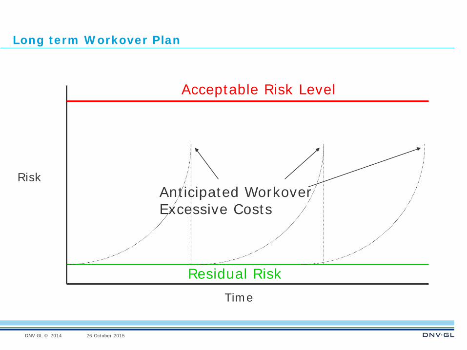
DNV GL © 2014 26 October 2015
Risk
Time
Acceptable Risk Level
Residual Risk
Anticipated Workover Excessive Costs
Long term Workover Plan
DNV GL © 2014 26 October 2015
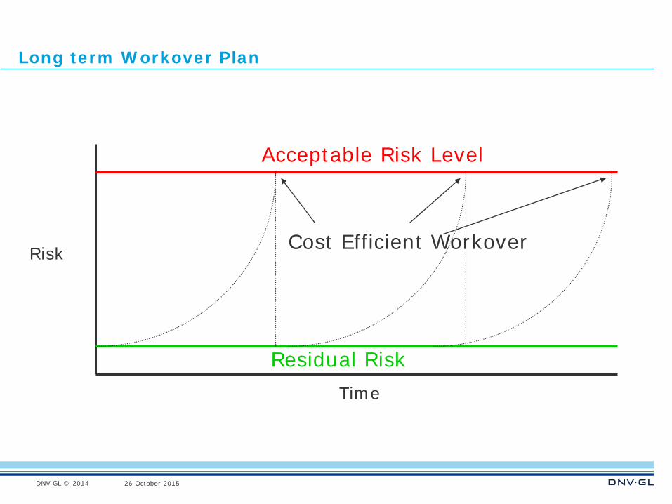
Risk
Time
Acceptable Risk Level
Residual Risk
Cost Efficient Workover
Long term Workover Plan
DNV GL © 2014 26 October 2015
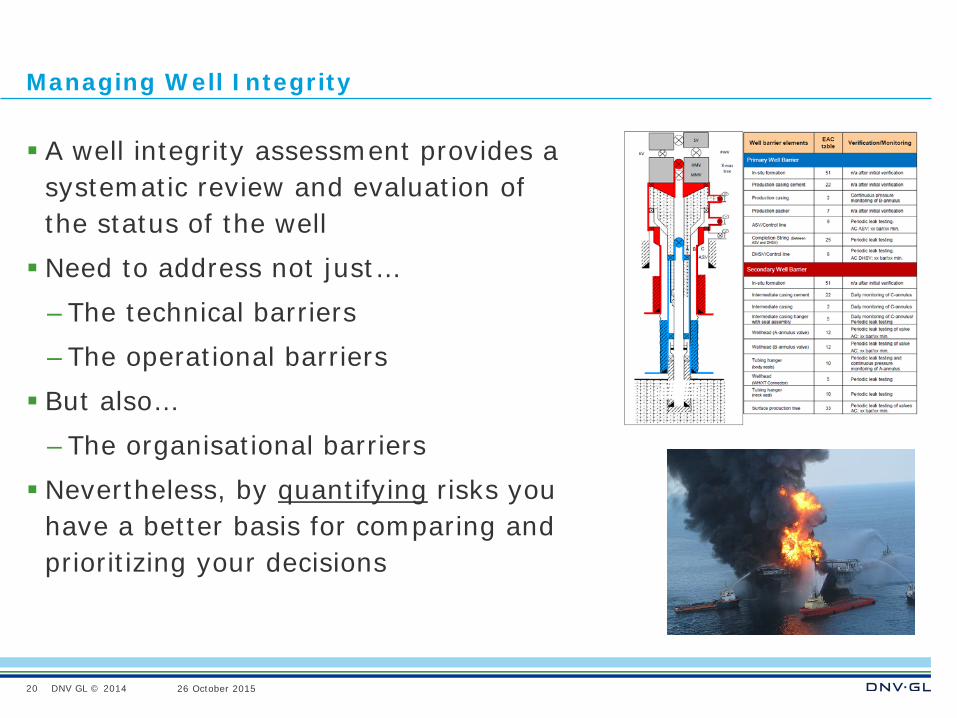
Managing Well Integrity
A well integrity assessment provides a systematic review and evaluation of the status of the well Need to address not just…
– The technical barriers – The operational barriers But also…
– The organisational barriers Nevertheless, by quantifying risks you
have a better basis for comparing and prioritizing your decisions
20
DNV GL © 2014 26 October 2015
SAFER, SMARTER, GREENER
www.dnvgl.com
Thank you for your attention!
21
Tobias V. Alvarenga [email protected] +55 21 3722 7260


![QRA Technical Guidance - National Environment Agency · QRA Technical Guidance [Revision No: 1] [Date of Revision: 31st March 2016] Contents 1 QRA Study ...](https://static.fdocuments.us/doc/165x107/5ace3a7d7f8b9a1d328b8ec2/qra-technical-guidance-national-environment-technical-guidance-revision-no-1.jpg)


