
Oil Cooler Heat Exchanger - Latest
23
UNIVERSITY OF NEBRASKA – LINCOLN Oil Cooler Heat Exchanger Double-Pipe Heat Exchanger Design Kailash Kumar Jain Munoth and Rohit Thallam Due Date: 12/11/2014
-
Upload
kailash-jain -
Category
Documents
-
view
47 -
download
4
Transcript of Oil Cooler Heat Exchanger - Latest

university of nebraska – lincoln
Oil Cooler Heat Exchanger
Double-Pipe Heat Exchanger Design
Kailash Kumar Jain Munoth and Rohit Thallam
Due Date:
12/11/2014

Table of Contents
Nomenclature.................................................................................................... 3Greek Symbols.........................................................................................................................................4
Subscripts................................................................................................................................................4
Summary........................................................................................................... 5Introduction.......................................................................................................5
Background Information..........................................................................................................................5
Problem Statement.................................................................................................................................6
Assumptions............................................................................................................................................7
Design Methodology..........................................................................................7Basic Formulas.........................................................................................................................................7
Design Calculations............................................................................................9Typical Design..........................................................................................................................................9
Best Design............................................................................................................................................12
Conclusion and Recommendations...................................................................14Appendix..........................................................................................................15
Parametric Studies.................................................................................................................................15
Tables....................................................................................................................................................17
References....................................................................................................... 18
2 | P a g e

NomenclatureA−heat transfer surfacearea ,m2ℜ−reynolds number
Ac−net freefloewarea,m2Q−heat load∨duty ,W
De−equivalent diameter for heat transfer ,mT−absolute temperature, K
Dh−hydraulic diameter for pressure drop,m ΔT−temperature difference ,K
d−diameter of inner tube,mU o−overallheat transfer coefficient ,W
m2−K
D−diame ter of the annulus ,mum−mean velocity , m/s
f−fanning friction factor Pr−PrandtlNumber
h−heat transfer coefficient , W
m2−KΔ p−pressuredrop ,Pa
H f−height of the fin ,mP−perimeter ,m
k−thermal conductivity , Wm−K
Nu−nusselt number
L−nominal lengthof the exchanger section ,alsolengthof longitudinal fin ,m
m−mass flow rate ,Kgm−s
N f−number of fins per tube
Nhp−numberof hairpins
N t−number of tubes
3 | P a g e
Greek Symbols
η f−fin efficiency
ηo−overall fin efficiency
ηp−pump efficiency
μ−dynamic viscosity ,
ρ−massdensity , Kgm3
δ−finthi ckness ,m
Subscripts
b−bulk
c−crosssection , cold
e−equivalent
f−fins , fin−side , frictional
h−hot , heat transfer
h−hydraulic
hp−hairpins
i−inside of tubes
o−outside of bare tubes
t−total
u−unfinned
w−wall,wetted
4 | P a g e

Summary
Heat exchangers are one of the most important devices in cooling and heating process in
factories, buildings, transports and others. The heat exchanger is also used to support cooling processes
in power plants. For this project, the oil cooler is designed of double pipe and is constructed to cool hot
oil using sea water.
In this report, the best design for a double pipe heat exchangers is chosen based on many
factors such as size, cleaning friendly, heat transfer coefficient, economy and so on. For this project, hot
oil is coming into the heat exchanger and water is used to cool the oil and as a result heat is exchanged.
The inlet and outlet temperatures of both fluids are specified. In this project, the properties of materials
are given and therefore there is no needed to experiment with different types of materials. Also, the
proper fouling factors are selected to account for the fluid properties. The initial size assumption of the
heat exchanger is given but one can start with one arbitrary inner tube and then check geometrical
parameters to determine the effects of these changes as parametric studies are done in order to find
the best design. Cost analysis of the selected design is also done for better decision making. After
choosing the best design, the heat exchanges should be ready to fabricate. In this project, the geometric
properties are taken as variables to come up with a best design that produces a high heat transfer
coefficient.
Introduction
Background Information
Temperature can be defined as degree of hotness or coldness of an object. Heat exchangers are
used to transfer that heat energy from one substance to another. In process units it is necessary to
control the temperature of incoming and outgoing streams. These streams can either be gases or
liquids. Heat exchangers raise or lower the temperature of these streams by transferring heat to (or)
from the stream.
Heat exchangers are devices that exchange the heat between two fluids of different
temperatures that are separated by a solid wall. The temperature gradient, or the differences in
temperature facilitate this transfer of heat. Transfer of heat happens by three principle means:
conduction, convection and radiation. In the use of heat exchangers radiation does take place. However,
5 | P a g e

in comparison to conduction and convection, radiation does not play a major role. Conduction occurs as
the heat from the higher temperature fluid passes through the solid wall. To maximize the heat transfer,
the wall should be thin and made of a very conductive material.
In a heat exchanger forced convection allows for the transfer of heat of one moving stream to
another moving stream. With convection as heat is transferred through the pipe wall it is mixed into the
stream and the flow of the stream removes the transferred heat. This maintains a temperature gradient
between the two fluids.
Figure 1: Double Pipe Heat Exchanger
Problem Statement
A double pipe heat exchanger is used in the industry as a condenser for chemical processes and
cooling fluid processes. A double pipe heat exchanger is designed in a decently large size for large
applications in the industry. For this project, the oil cooler is a double pipe heat exchanger that needs to
be designed with sea water. The decision was made to use a hairpin heat exchanger for the oil cooler.
The mass flow rate, inlet and outlet temperatures of fluids, fluid properties, length of heat exchanger,
and material have already been decided for this project. Freedom is still available in the selection of
proper fouling factors. The geometrical information that is provided is to initiate the analysis. The
geometrical properties will be taken as variable parameters to come up with a suitable design. We start
with one inner tube and completing the hand calculation, we study the variation of critical qualitative
parameters by changing geometrical properties. Cost analysis of the selected design has to be made for
the best design chosen. The report will contain material selection, mechanical design parameters and
cost analysis.
6 | P a g e
Assumptions
The Inner and Outer tube have constant fouling resistance.
Sea water fouling factor will be approximated by the city water fouling coefficient.
Sea water fluid properties will be approximated from the saturated water table.
Heat transfer coefficient is calculated based on the outside surface area.
Cost is not an important factor during design stages.
Corrosion does not have a huge impact on heat transfer coefficient.
Design Methodology
Basic Formulas
Heat Duty:
Q=(m Cp)c∆T c=(mC p)h∆T h
Inner Tube – Sea Water:
um=mc
ρ c πd i2
4
ℜ=ρcumd iμ
f=¿¿
Nub=( f2)(ℜb)(Prb)
1+8.7( f2 )12(Prb
. −1)
hi=Nub∗kd i
Annulus – Oil:
7 | P a g e

um=mh
ρh Ac
where Ac=π4
(Di2−do
2 )
ℜ=ρhumDh
μwhereD h=
4 A c
Pw
=Di−do
Nub=( f2)(ℜb)(Prb)
1+8.7( f2 )12(Prb
. −1)
ho=Nub∗kDe
where De=Di2−do
2
do
Overall heat transfer coefficient (with fouling):
U f=dod ihi
+do Rfi
d i+do ln (
dod i
)
2k+R fo+
1ho
−1/2
Overall heat transfer coefficient (without fouling):
U c=dod ihi
+do ln (
dod i
)
2k+1ho
−1/2
Cleanliness factor:
CF=U f
U c
Total heat transfer area:
Ao=Q
U o ΔT m
Total heat transfer area (without fouling):
Aoc=Q
U c ΔT m
Total heat transfer area (with fouling):
8 | P a g e

Aof=Q
U f ΔT m
Number of hairpins:
Nhp=Ao
Ahp
where Ahp=2π do L
Percentage Over Surface:
OS=100∗U c∗1−CF
U c∗CF
Pressure Drop:
Inner Tube
∆ pt=4 f2Ld i
ρum2
2N hp
Annulus
∆ pa=4 f2 LDh
ρum2
2Nhp
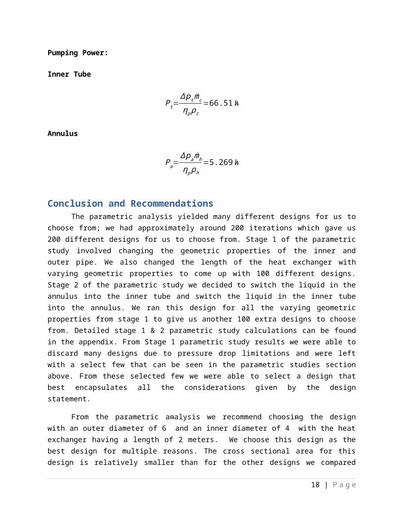
Pumping Power:
Inner Tube
Pt=∆ p t mc
ηp ρc
Annulus
Pa=∆ pamh
ηp ρh
Design Calculations
Typical Design Fluid SAE-30 Oil Sea Water
9 | P a g e

Inlet Temperature, C 65 20Outlet Temperature, C 55 30Pressure drop limitations, kPa 140 5Total mass flow rate, kg/s 2.5 1.2Density , kg/m3 912 1013.4Specific Heat , KJ/kg-k 1.901 4.004Viscosity , kg/m-s 0.075 9.64 x 10⁻⁴
Prandtl Number 1050 6.29Thermal Conductivity, W/m-K 0.1442 0.639
d i=2.067∈, do=2.375∈, Di=3.548∈, L=3m,
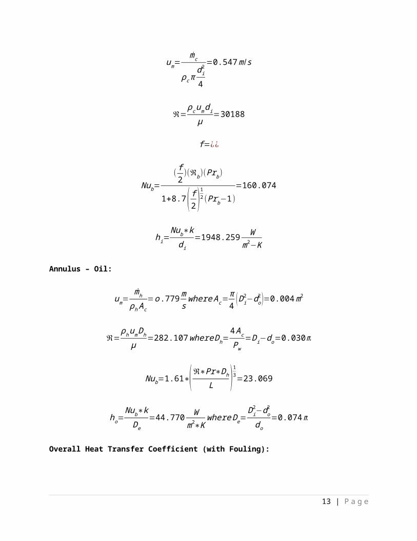
Inner Tube – Sea Water:
um=mc
ρ c πd i2
4
=0.547m /s
ℜ=ρcumd iμ
=30188
f=¿¿
Nub=( f2)(ℜb)(Prb)
1+8.7( f2 )12(Prb
. −1)=160.074
hi=Nub∗kd i
=1948.259 Wm2−K
Annulus – Oil:
um=mh
ρh Ac
=o.779mswhere Ac=
π4
(D i2−do
2 )=0.004m2
ℜ=ρhumDh
μ=282.107whereDh=
4 Ac
Pw
=Di−do=0.030m
Nub=1.61∗( ℜ∗Pr∗Dh
L )13=23.069
10 | P a g e

ho=Nub∗kDe
=44.770 Wm2∗K
where De=D i2−do
2
d o
=0.074m
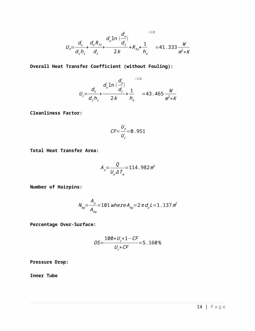
Overall Heat Transfer Coefficient (with Fouling):
U f=dod ihi
+do Rfi
d i+do ln (
dod i
)
2k+R fo+
1ho
−1/2
=41.333W
m2∗K
Overall Heat Transfer Coefficient (without Fouling):
U c=dod ihi
+do ln (
dod i
)
2k+1ho
−1/2
=43.465W
m2∗K
Cleanliness Factor:
CF=U f
U c
=0.951
Total Heat Transfer Area:
Ao=Q
U o ΔT m
=114.982m2
Number of Hairpins:
Nhp=Ao
Ahp
=101where Ahp=2 π doL=1.137m2
Percentage Over-Surface:
OS=100∗U c∗1−CF
U c∗CF=5.160%
Pressure Drop:
Inner Tube
∆ pt=4 f2Ld i
ρum2
2N hp=41347.662 Pa
11 | P a g e

Annulus
∆ pa=4 f2 LDh
ρum2
2Nhp=709270.196Pa
Pumping Power:
Inner Tube
Pt=∆ p t mc
ηp ρc=61.201W
Annulus
Pa=∆ pamh
ηp ρh=2430.339W
Best Designd i=4.026∈, do=4.500∈, Di=6.065∈, L=2m
Inner Tube – SAE-30 Oil:
um=mc
ρ c πd i2
4
=0.334m /s
ℜ=ρcumd iμ
=415.032
f=¿¿
Nub=( f2)(ℜb)(Prb)
1+8.7( f2 )12(Prb
. −1)=33.064
hi=Nub∗kd i
=46.624 Wm2∗K
Annulus – Sea Water:
12 | P a g e
um=mh
ρh Ac
=0.141mswhere Ac=
π4
(Di2−do
2 )=0.008m2
ℜ=ρhumDh
μ=5906.2where Dh=
4 Ac
Pw
=D i−do=0.040m
Nub=( f2)(ℜb)(Prb)
1+8.7( f2 )12(Prb
. −1)=41.392
ho=Nub∗kDe
=283.407 Wm2∗K
where De=Di2−do
2
do=0.093m
Overall heat transfer coefficient (with fouling):
U f=dod ihi
+do Rfi
d i+do ln (
dod i
)
2k+R fo+
1ho
−1/2
=34.74W
m2∗K
Overall heat transfer coefficient (without fouling):
U c=dod ihi
+do ln (
dod i
)
2k+1ho
−1/2
=36.2W
m2∗K
Cleanliness factor:
CF=U f
U c
=0.96
Total heat transfer area:
Ao=Q
U o ΔT m
=136.79m2
Number of hairpins:
Nhp=Ao
Ahp
=95where Ahp=2π do L=1.436m2
13 | P a g e
Percentage Over Surface:
OS=100∗U c∗1−CF
U c∗CF=4.198%
Pressure Drop:
Inner Tube
∆ pt=4 f2Ld i
ρum2
2N hp=19410.2Pa
Annulus
∆ pa=4 f2 LDh
ρum2
2Nhp=3559.7Pa
Pumping Power:
Inner Tube
Pt=∆ p t mc
ηp ρc=66.51W
Annulus
Pa=∆ pamh
ηp ρh=5.269W
Conclusion and RecommendationsThe parametric analysis yielded many different designs for us to choose from; we had
approximately around 200 iterations which gave us 200 different designs for us to choose from. Stage 1 of the parametric study involved changing the geometric properties of the inner and outer pipe. We also changed the length of the heat exchanger with varying geometric properties to come up with 100 different designs. Stage 2 of the parametric study we decided to switch the liquid in the annulus into the inner tube and switch the liquid in the inner tube into the annulus. We ran this design for all the varying geometric properties from stage 1 to give us another 100 extra designs to choose from. Detailed stage 1 & 2 parametric study calculations can be found in the appendix. From Stage 1 parametric study results we were able to discard many designs due to pressure drop limitations and were left with a select few
14 | P a g e

that can be seen in the parametric studies section above. From these selected few we were able to select a design that best encapsulates all the considerations given by the design statement.
From the parametric analysis we recommend choosing the design with an outer diameter of 6” and an inner diameter of 4” with the heat exchanger having a length of 2 meters. We choose this design as the best design for multiple reasons. The cross sectional area for this design is relatively smaller than for the other designs we compared but this also allows us to no dissipate too much heat through conduction of the material. The sea water will be place inside the annulus and this gave us a Reynolds number of 415.03 which is highly laminar with a friction factor of 0.026. The heat transfer coefficient on the inner tube was 46.624 W/m^2*K which is fairly higher than most of the other designs. The SAE-30 oil is placed inside the inner tube and we calculated a Reynolds number of 5906.2 which is turbulent flow. The heat transfer coefficient in the annulus is 283.4 W/m^2*K which is very high compared to the designs compared in the parametric study. We have found that this design has a clean overall heat transfer coefficient of 36 W/m^2*K and fouled heat transfer coefficient of 34.7 W/m^2*K with a cleaning factor of 0.0.96. This cleaning factor is very high so we don’t have to maintain a regular cleaning schedule to clean the heat exchanger. While maintain high levels of cleanliness factors we can assume that the overall heat transfer coefficient will be closer to the clean side than the fouled giving the heat exchanger a very good heat transfer coefficient. The pressure drop from the tube side and the annulus are very similar to the other designs and so there really is not a big number to deal with. Lastly, the pumping power is small enough to power required to pump the liquids and we are not consuming a lot of power to make it affordable. We have chosen to recommend this design because it has a good heat transfer coefficient for the pumping power that is required.
Appendix
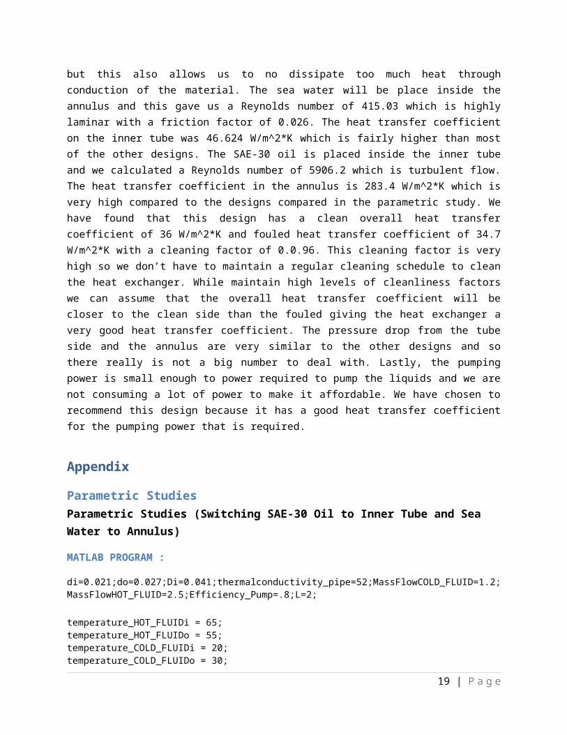
Parametric StudiesParametric Studies (Switching SAE-30 Oil to Inner Tube and Sea Water to Annulus)
MATLAB PROGRAM :
di=0.021;do=0.027;Di=0.041;thermalconductivity_pipe=52;MassFlowCOLD_FLUID=1.2;MassFlowHOT_FLUID=2.5;Efficiency_Pump=.8;L=2;
temperature_HOT_FLUIDi = 65;temperature_HOT_FLUIDo = 55;temperature_COLD_FLUIDi = 20;temperature_COLD_FLUIDo = 30; density_HOT_FLUID = 912;density_COLD_FLUID=1013.4;shHOT_FLUID = 1901;shCOLD_FLUID=4004;Prandtl_HOT_FLUID =1050;Prandtl_COLD_FLUID=6.29;tcHOT_FLUID=0.1442;tcCOLD_FLUID=0.639;R_fo = 0.000176;R_fi=0.000088;Mass_Flow_Rate_HOT_FLUID = 2.5;Mass_Flow_Rate_COLD_FLUID = 1.2;
15 | P a g e

viscosity_COLD_FLUID = 0.964*10^-3;viscosity_HOT_FLUID= 0.075;Q = 47525;Tm = 10; UmC = Mass_Flow_Rate_COLD_FLUID/(density_COLD_FLUID*(pi/4)*(Di^2-do^2))HydDia=pi*(Di^2-do^2)/(pi*(Di+do))ReC = density_COLD_FLUID*UmC*HydDia/(viscosity_COLD_FLUID)de=(Di^2-do^2)/doHeat_Transfer_Coefficient_Cold_Fluid=0;
if ReC > 2300 fC = double(((1.58*log(ReC))-3.28)^(-2)) NubCOLD_FLUID = ((fC/2)*ReC*Prandtl_COLD_FLUID)/((1+8.7*(Prandtl_COLD_FLUID-1)*(fC/2)^0.5)) Heat_Transfer_Coefficient_Cold_Fluid = NubCOLD_FLUID*tcCOLD_FLUID/deend UmH = Mass_Flow_Rate_HOT_FLUID/((density_HOT_FLUID*(pi/4)*(di^2)))ReH = density_HOT_FLUID*UmH*di/(viscosity_HOT_FLUID)Heat_Transfer_Coefficient_Hot_Fluid=0; if ReH > 2300 fH = double((1.58*log(ReH)-3.28)^(-2)) NubHOT_FLUID = (fH/2)*ReH*Prandtl_HOT_FLUID/(1+8.7*(Prandtl_HOT_FLUID1)*(fH/2)^0.5) Heat_Transfer_Coefficient_Hot_Fluid = NubHOT_FLUID*tcHOT_FLUID/diend if ReH < 2300 fH = double((1.58*log(ReH)-3.28)^(-2)) NubHOT_FLUID = 1.61*(ReH*Prandtl_HOT_FLUID*HydDia/L)^(1/3) Heat_Transfer_Coefficient_Hot_Fluid = NubHOT_FLUID*tcHOT_FLUID/diendOverallHTC_Fouling_Inv = do/(di*Heat_Transfer_Coefficient_Hot_Fluid) + do*R_fi/di + do*log(do/di)/(2*thermalconductivity_pipe)+ R_fo + 1/Heat_Transfer_Coefficient_Cold_Fluid
OverallHTC_Fouling = 1/OverallHTC_Fouling_InvOverallHTSArea = Q*OverallHTC_Fouling_Inv/Tm HeatTranAreaForHairPin = 2*pi*do*LNoOfHairPins = OverallHTSArea/HeatTranAreaForHairPinNoOfHairPins = ceil(NoOfHairPins) CleanOverallHTCoef_inv = do/(di*Heat_Transfer_Coefficient_Hot_Fluid) + do*log(do/di)/(2*thermalconductivity_pipe) + 1/(Heat_Transfer_Coefficient_Cold_Fluid)CleanOverallHTCoef = 1/CleanOverallHTCoef_inv CleanlinessFactor = OverallHTC_Fouling/CleanOverallHTCoef
16 | P a g e

OverSurface = 100 * (1-CleanlinessFactor)/CleanlinessFactorPresureDropCOLD_FLUID = 4*fC*2*L*NoOfHairPins*density_HOT_FLUID*UmC^2/(2*di)PresureDropHOT_FLUID = 4*fH*2*L*NoOfHairPins*density_COLD_FLUID*UmH^2/(2*HydDia)PumpingPowerCOLD_FLUID = PresureDropCOLD_FLUID * MassFlowCOLD_FLUID/(Efficiency_Pump*density_COLD_FLUID)PumpingPowerHOT_FLUID = PresureDropHOT_FLUID * MassFlowHOT_FLUID/(Efficiency_Pump*density_HOT_FLUID) if PresureDropCOLD_FLUID > 5000 || PresureDropHOT_FLUID > 140000 fprintf('Presure drop exceeded') return;end
Parametric Studies (Sea Water-Inner Tube and SAE 30-Oil Outer Tube Changing Geometric Properties: Di, do, di, and L)
[Excel Sheet Calculations are attached]
17 | P a g e
Tables
18 | P a g e
References
Kakac, Sadik, Hongtan Liu and Anchasa Pramuanjaroenkij. Heat Exchangers. Third. New York: CRC Press, n.d. Book. 9 December 2014.
19 | P a g e


