OHVT Technology Roadmap - UNT Digital Library
88
DOE/OSTI-11690/R2 OHVT TECHNOLOGY ROADMAP U.S. Department of Energy Office of Heavy Vehicle Technologies (OHVT) Office of Transportation Technologies February 2000
Transcript of OHVT Technology Roadmap - UNT Digital Library

DOE/OSTI-11690/R2
OHVTTECHNOLOGY ROADMAP
U.S. Department of EnergyOffice of Heavy Vehicle Technologies (OHVT)
Office of Transportation Technologies
February 2000

This report has been reproduced from the best available copy.
Reports are available to the public from the following source.
National Technical Information Service5285 Port Royal RoadSpringfield, VA 22161Telephone 703-605-6000 (1-800-553-6847)TDD 703-487-4639Fax 703-605-6900E-mail [email protected] site www.ntis.gov/ordering.htm
Reports are available to U.S. Department of Energy (DOE) employees, DOE contractors, EnergyTechnology Data Exchange (ETDE) representatives, and International Nuclear InformationSystem (INIS) representatives from the following source.
Office of Scientific and Technical InformationP.O. Box 62Oak Ridge, TN 37831Telephone 865-576-8401Fax 865-576-5728E-mail [email protected] site www.osti.gov/products/sources.html
Reports produced after January 1, 1996, are generally available via the DOE Information Bridge.
Web site www.doe.gov/bridge
This report was prepared as an account of work sponsored by an agency ofthe United States government. Neither the United States government norany agency thereof, nor any of their employees, makes any warranty,express or implied, or assumes any legal liability or responsibility for theaccuracy, completeness, or usefulness of any information, apparatus,product, or process disclosed, or represents that its use would not infringeprivately owned rights. Reference herein to any specific commercial product,process, or service by trade name, trademark, manufacturer, or otherwise,does not necessarily constitute or imply its endorsement, recommendation,or favoring by the United States government or any agency thereof. Theviews and opinions of authors expressed herein do not necessarily state orreflect those of the United States government or any agency thereof.

DOE/OSTI-11690/R2
U.S. Department of EnergyOffice of Heavy Vehicle TechnologiesOffice of Transportation Technologies
OHVT Technology Roadmap
Date published—February 2000
iii
CONTENTS
FIGURES . . . . . . . . . . . . . . . . . . . . . . . . . . . . . . . . . . . . . . . . . . . . . . . . . . . . . . . . . . . . . . . . . . . . v
TABLES . . . . . . . . . . . . . . . . . . . . . . . . . . . . . . . . . . . . . . . . . . . . . . . . . . . . . . . . . . . . . . . . . . . vii
ACRONYMS AND ABBREVIATIONS . . . . . . . . . . . . . . . . . . . . . . . . . . . . . . . . . . . . . . . . . . ix
FOREWORD . . . . . . . . . . . . . . . . . . . . . . . . . . . . . . . . . . . . . . . . . . . . . . . . . . . . . . . . . . . . . . . . xi
ACKNOWLEDGMENTS . . . . . . . . . . . . . . . . . . . . . . . . . . . . . . . . . . . . . . . . . . . . . . . . . . . . . xiii
EXECUTIVE SUMMARY . . . . . . . . . . . . . . . . . . . . . . . . . . . . . . . . . . . . . . . . . . . . . . . . . . . . . xv
1. INTRODUCTION . . . . . . . . . . . . . . . . . . . . . . . . . . . . . . . . . . . . . . . . . . . . . . . . . . . . . . . . . 1
2. STRATEGIC IMPORTANCE OF THE HEAVY VEHICLE TECHNOLOGY PROGRAM . . . . . . . . . . . . . . . . . . . . . . . . . . . . . . . . . . . . . . . . . . . . . . . . 52.1 THE OHVT STRATEGY . . . . . . . . . . . . . . . . . . . . . . . . . . . . . . . . . . . . . . . . . . . . . . . 62.2 BENEFITS OF A SUCCESSFUL PROGRAM . . . . . . . . . . . . . . . . . . . . . . . . . . . . . . . 7
3. TECHNICAL PLAN . . . . . . . . . . . . . . . . . . . . . . . . . . . . . . . . . . . . . . . . . . . . . . . . . . . . . . . 93.1 CLASS 7 & 8 TRUCKS . . . . . . . . . . . . . . . . . . . . . . . . . . . . . . . . . . . . . . . . . . . . . . . . . 9
3.1.1 Goals . . . . . . . . . . . . . . . . . . . . . . . . . . . . . . . . . . . . . . . . . . . . . . . . . . . . . . . . . . . . 93.1.2 Engine Efficiency for 10-mpg Truck . . . . . . . . . . . . . . . . . . . . . . . . . . . . . . . . . . . 93.1.3 Power Requirements for 10-mpg Truck . . . . . . . . . . . . . . . . . . . . . . . . . . . . . . . . 123.1.4 Emissions . . . . . . . . . . . . . . . . . . . . . . . . . . . . . . . . . . . . . . . . . . . . . . . . . . . . . . . 143.1.5 Fuels Utilization—Advanced Petroleum-Based Fuel Program . . . . . . . . . . . . . . 193.1.6 Fuels Utilization—Alternative Fuels Program . . . . . . . . . . . . . . . . . . . . . . . . . . . 24
3.2 CLASS 3–6 TRUCKS . . . . . . . . . . . . . . . . . . . . . . . . . . . . . . . . . . . . . . . . . . . . . . . . . 303.2.1 Goals . . . . . . . . . . . . . . . . . . . . . . . . . . . . . . . . . . . . . . . . . . . . . . . . . . . . . . . . . . . 303.2.2 Emissions Reductions and Improved Fuel Economy . . . . . . . . . . . . . . . . . . . . . . 303.2.3 Fuels and Lubricants . . . . . . . . . . . . . . . . . . . . . . . . . . . . . . . . . . . . . . . . . . . . . . 34
3.3 CLASS 1 & 2 TRUCKS . . . . . . . . . . . . . . . . . . . . . . . . . . . . . . . . . . . . . . . . . . . . . . . . 343.3.1 Goals . . . . . . . . . . . . . . . . . . . . . . . . . . . . . . . . . . . . . . . . . . . . . . . . . . . . . . . . . . . 343.3.2 35% Fuel-Efficiency Improvement—45% Efficient Diesel Engine . . . . . . . . . . 343.3.3 Emissions . . . . . . . . . . . . . . . . . . . . . . . . . . . . . . . . . . . . . . . . . . . . . . . . . . . . . . . 383.3.4 Noise, Vibration, and Harshness; Smoke and Odor; Cold Starts . . . . . . . . . . . . . 423.3.5 Fuels and Lubricants . . . . . . . . . . . . . . . . . . . . . . . . . . . . . . . . . . . . . . . . . . . . . . 45
3.4 ENABLING AND SUPPORTING TECHNOLOGIES . . . . . . . . . . . . . . . . . . . . . . . . 453.4.1 Emission Controls (Exhaust Aftertreatment) . . . . . . . . . . . . . . . . . . . . . . . . . . . . 453.4.2 Combustion Technology . . . . . . . . . . . . . . . . . . . . . . . . . . . . . . . . . . . . . . . . . . . 483.4.3 Materials . . . . . . . . . . . . . . . . . . . . . . . . . . . . . . . . . . . . . . . . . . . . . . . . . . . . . . . . 493.4.4 Environmental Science and Health Effects Program . . . . . . . . . . . . . . . . . . . . . . 533.4.5 Truck Safety . . . . . . . . . . . . . . . . . . . . . . . . . . . . . . . . . . . . . . . . . . . . . . . . . . . . . 553.4.6 Engineering Simulations and Modeling . . . . . . . . . . . . . . . . . . . . . . . . . . . . . . . . 58
4. PROGRAM SUMMARY . . . . . . . . . . . . . . . . . . . . . . . . . . . . . . . . . . . . . . . . . . . . . . . . . . 654.1 PROGRAM GOALS . . . . . . . . . . . . . . . . . . . . . . . . . . . . . . . . . . . . . . . . . . . . . . . . . . 65

iv
4.2 PROGRAM APPROACH . . . . . . . . . . . . . . . . . . . . . . . . . . . . . . . . . . . . . . . . . . . . . . 654.3 SCHEDULE AND MILESTONES . . . . . . . . . . . . . . . . . . . . . . . . . . . . . . . . . . . . . . . 66
5. REFERENCES . . . . . . . . . . . . . . . . . . . . . . . . . . . . . . . . . . . . . . . . . . . . . . . . . . . . . . . . . . . 67
APPENDIX A. OHVT WORKSHOPS AND MEETINGSTO SOLICIT CUSTOMER INPUT . . . . . . . . . . . . . . . . . . . . . . . . . . . . . . . . . . . . . . . . . . A-1
APPENDIX B. MULTIYEAR PROGRAM PLANS . . . . . . . . . . . . . . . . . . . . . . . . . . . . . . . . B-1

v
FIGURES
1. Trucks account for an increasing amount of highway transportation energy use . . . . . . 22. The nation’s economy is linked to efficient heavy vehicle transportation . . . . . . . . . . . . 53. OHVT Program strategy . . . . . . . . . . . . . . . . . . . . . . . . . . . . . . . . . . . . . . . . . . . . . . . . . . 64. Heavy-duty diesel truck emissions relative to total on-road emissions . . . . . . . . . . . . . . 75. Highway petroleum-use reductions from OHVT-supported technologies . . . . . . . . . . . . 76. Increasing diesel-cycle engine efficiency . . . . . . . . . . . . . . . . . . . . . . . . . . . . . . . . . . . . 107. Projected contributions of advanced technologies to diesel engine
efficiency improvement to achieve an increase of 15% . . . . . . . . . . . . . . . . . . . . . . . . . 108. Distribution of power requirements for a typical Class 8 truck . . . . . . . . . . . . . . . . . . . 129. Evolution of heavy-duty diesel engine emissions control . . . . . . . . . . . . . . . . . . . . . . . 15
10. Multifaceted emission-control approach necessary to ensure that fuel-economy, cost, and durability goals are in harmony with ambitious emission targets . . . . . . . . . . . . . . . . . . . . . . . . . . . . . . . . . . . . . . . . . . . . . . . 18
11. Light-duty diesel Tier-1 and Tier-2 PM and NOx emissions standards . . . . . . . . . . . . . 3812. Environmental Science and Health Effects Program—focus areas for
atmospheric-effects research . . . . . . . . . . . . . . . . . . . . . . . . . . . . . . . . . . . . . . . . . . . . . . 5413. Key activities and schedule of OHVT . . . . . . . . . . . . . . . . . . . . . . . . . . . . . . . . . . . . . . 66

vii
TABLES
1. Targets of opportunity . . . . . . . . . . . . . . . . . . . . . . . . . . . . . . . . . . . . . . . . . . . . . . . . . . . 62. Summary of engine-efficiency parameters, technical targets,
and barriers critical to 50% efficient engine . . . . . . . . . . . . . . . . . . . . . . . . . . . . . 113. Summary of 10-mpg truck parameters, technical targets, and barriers . . . . . . . . . . . . . 144. Summary of goals, technical targets, and barriers for Class 7 & 8 emissions . . . . . . . . 185. Summary of technical targets and barriers for advanced petroleum-based
fuels for medium & heavy-duty applications . . . . . . . . . . . . . . . . . . . . . . . . . . . . . . . . . 216. Summary of technical targets and barriers for Class 7 & 8
Fischer-Tropsch-fueled diesel engine . . . . . . . . . . . . . . . . . . . . . . . . . . . . . . . . . . . . . . . 277. Summary of technical targets and barriers for Classes 7 & 8
dedicated gaseous-fuel engine . . . . . . . . . . . . . . . . . . . . . . . . . . . . . . . . . . . . . . . . . . . . 278. Technical targets and research goals for emissions from Class 3–6 trucks . . . . . . . . . . 319. Key efficiency-related characteristics of engines of approximate size and power
or Class 1 & 2 trucks . . . . . . . . . . . . . . . . . . . . . . . . . . . . . . . . . . . . . . . . . . . . . . . . . . . 3510. Summary of pickup/SUV diesel engine targets and barrier
technical approach . . . . . . . . . . . . . . . . . . . . . . . . . . . . . . . . . . . . . . . . . . . . . . . . . . . . . 3711. Range of full useful life light-duty FTP emissions standards
and DOE research goals . . . . . . . . . . . . . . . . . . . . . . . . . . . . . . . . . . . . . . . . . . . . . . . . . 4012. Diesel emission-control technologies . . . . . . . . . . . . . . . . . . . . . . . . . . . . . . . . . . . . . . . 48

ix
ACRONYMS AND ABBREVIATIONS
AAMA American Automobile Manufacturers AssociationABS antilock braking systemAC alternating currentANL Argonne National LaboratoryANPRM Advanced Notice of Proposed Rule MakingAPB Advanced Petroleum-BasedATA American Trucking AssociationBmep brake mean effective pressureBsfc brake specific fuel consumptionCd drag coefficientCAPS Clean Air PartnersCARB California Air Resource BoardCFD computational fluid dynamicsCIDI compression ignition, direct injectionCNG compressed natural gasCO carbon monoxideCRT continuously regenerating trapCVT continuously variable transmissionDC direct currentDDC Detroit Diesel CorporationDECSE diesel emission controls and sulfur effectsDEE diethyl etherDFNG dual-fuel natural gasDI direct injectionDING direct injection natural gasDME Dimethyl etherDMM dimethoxy methaneDOE U.S. Department of EnergyDOE-SC U.S DOE Office of ScienceEGR exhaust gas recirculationEMA Engine Manufacturers AssociationEPA U.S. Environmental Protection AgencyES&HE Environmental Science and Health EffectsF-T Fischer-TropschFIE fuel-injection equipmentFTP Federal Test ProcedureGDP gross domestic productGM General MotorsGPRA Government Performance and Results ActGVW gross vehicle weightGVWR gross vehicle weight ratingHAP hazardous air pollutantHTML High Temperature Materials LaboratoryIC internal combustionIDI indirect injection

x
LDT light-duty truckLDV light-duty vehicleLES large-eddy simulationLNG liquified natural gasLPG liquified petroleum gasMDV medium-duty vehicleMECA Manufacturers of Emission Controls AssociationMEMS micro electro-mechanical systemMPG miles per gallonMYPP multi-year program planNAAQS National Ambient Air Quality StandardsNG natural gasNMHC non-methane hydrocarbonsNOx nitrogen oxideNREL National Renewable Energy LaboratoryNVH noise, vibration, and harshnessOAAT Office of Advanced Automotive TechnologiesOHVT Office of Heavy Vehicle TechnologiesORNL Oak Ridge National LaboratoryOTT Office of Transportation TechnologiesPC passenger cars PING pilot ignition natural gasPM particulate matterPM2.5 particulate matter with aerodynamic diameter < 2.5µmPNGV Partnership for a New Generation of VehiclesPNNL Pacific Northwest National LaboratoryR&D research and developmentSAE Society of Automotive EngineersSCR selective catalyst reductionSFAA Solicitation for Financial Assistance ApplicationsSI spark ignitionSING spark-ignited natural gasSNL Sandia National LaboratoriesSOP statement of principlesSULEV super-ultra-low-emission vehicleSUV sport utility vehicleSwRI Southwest Research InstituteTBC thermal barrier coatingTCS traction control systemULEV ultra-low-emission vehicleVDC vehicle dynamic controlZEV zero-emission vehicle

xi
FOREWORD
The first OHVT Technology Roadmap was prepared by the U.S. Department of Energy(DOE) Office of Heavy Vehicle Technologies (OHVT) as a result of recommendations obtainedfrom industry representatives at a workshop convened in April 1996 to elicit input from DOE’sheavy vehicle industry customers, including truck and bus manufacturers, diesel enginemanufacturers, fuel producers, suppliers to these industries, and the trucking industry. TheTechnology Roadmap was reviewed by industry stakeholders, who provided comments at aworkshop in October 1996, held in conjunction with the Society of Automotive Engineers (SAE)International Truck and Bus Meeting and Exposition. The document was published in October1997. That Roadmap was a first step in crafting a common vision for a government research anddevelopment (R&D) partnership in this increasingly important transportation sector.
Since the preparation of the first Technology Roadmap, changes in emissions regulationsand advances in technology have presented new challenges and created new opportunities for theheavy vehicle industry. The current revision of the Technology Roadmap reflects these changes. This document, reviewed by selected industry stakeholders and by those who attended aworkshop held in conjunction with the November 1999 SAE International Truck and BusMeeting and Exposition, continues to serve as the foundation for the multiyear program planswhich guide the activities of the Office of Heavy Vehicle Technologies.

xiii
ACKNOWLEDGMENTS
The U.S. Department of Energy’s Office of Heavy Vehicle Technologies gratefullyacknowledges the following authors and contributors, who helped to revise the OHVTTechnology Roadmap.
U.S. Department of Energy: Sid Diamond, Steve Goguen, Michael Gurevich, Gurpreet Singh,and Richard Wares
Oak Ridge National Laboratory: Ron Bradley (overall project leader), Ron Graves, RayJohnson, David O’Kain, Arvid Pasto, Srdan Simunovic, and Phil Sklad. We’d also like to thankWalter Koncinski, Missy Sherrod, and Pam Wenzel for document preparation.
Argonne National Laboratory: Feng An, Jules Routbort, Raj Sekar, Frank Stodolsky, andKevin Stork
National Renewable Energy Laboratory: Doug Lawson, Paul Norton, George Sverdrup, and Keith Vertin
Pacific Northwest National Laboratory: Mark Smith and Jud Virden
Sandia National Laboratories: Bob Carling
Energetics: René Abarcar
We would also like to acknowledge the representatives of heavy vehicle manufacturers,engine manufacturers, heavy vehicle users, trade associations, and other laboratories fortheir reviews and comments. The following organizations provided input for either the October1997 version of the OHVT Technology Roadmap or the current revision.
American Trucking Association Ames Laboratory Brookhaven National Laboratory Caterpillar, Inc.Cummins Engine Company Detroit Diesel CorporationExxon Research and Engineering CompanyFEV Engine Technology Ford Motor Company General Motors Lawrence Livermore National Laboratory
Idaho National Engineeringand Environmental Laboratory
Los Alamos National Laboratory Lucas Varity Mack Trucks, Inc.Motor Coach Industries, Inc.Navistar PACCARRenault V.I.Southwest Research InstituteUnited Parcel Service
Dr. James J. EberhardtDirector, Office of Heavy Vehicle Technologies

xv
EXECUTIVE SUMMARY
The U.S. Department of Energy (DOE) Office of Heavy Vehicle Technologies (OHVT) wascreated in March 1996 to address the public-interest transportation-energy aspects of a set ofcustomers who at that time had been largely unrecognized, namely, the manufacturers, suppliers,and users of heavy transport vehicles (trucks, buses, rail, and inland marine). Previously, theDOE had focused its attention on meeting the needs of the personal-transport-vehicle customer(automobile manufacturers, suppliers, and users). Those of us who were of driving age at thetime of the 1973 oil embargo and the 1979 oil price escalation vividly recall the inconvenienceand irritation of having to wait in long lines for gasoline to fuel our cars. However, most of us,other than professional truck owners or drivers, were unaware of the impacts that thesedisruptions in the fuel supply had on those whose livelihoods depend upon the transport ofgoods.
Recognizing the importance of heavy vehicles to the national economic health, the DOEcreated OHVT with a mission to conduct, in collaboration with its industry partners and theirsuppliers, a customer-focused national program to research and develop technologies that willenable trucks and other heavy vehicles to be more energy-efficient and able to use alternativefuels while reducing emissions.
The Office of Heavy Vehicle Technologies convened a workshop in April 1996 to elicitinput from DOE’s heavy vehicle industry customers, including truck and bus manufacturers,diesel-engine manufacturers, fuel producers, suppliers to these industries, and the truckingindustry. The preparation of a “technology roadmap” was one of the key recommendations bythis customer group. Therefore, the OHVT Technology Roadmap* was developed in 1996 as afirst step in crafting a common vision for a government research and development (R&D)partnership in this increasingly important transportation sector. The approach used in developingthe OHVT Technology Roadmap was to
� formulate goals consistent with the U.S. Department of Energy Strategic Plan† required bythe Government Performance and Results Act (GPRA),
� assess the status of the technology,� identify technical targets,� identify barriers to achieving the technical targets,� develop an approach to overcoming the barriers, and� develop schedules and milestones.
This structure was followed for three groups of truck classification:
� Class 7 & 8: large, on-highway trucks;� Class 3–6: medium-duty trucks such as delivery vans; and� Class 1& 2: pickups, vans, and sport utility vehicles (SUVs).
The foundation of the OHVT Technology Roadmap is the Office of TransportationTechnologies Strategic Plan‡ and the DOE Strategic Plan. The Office of TransportationTechnologies Strategic Plan addresses the energy, economic, and environmental challenges inmeeting the future demand for transportation goods and services. Energy use by heavy vehicles

xvi
(trucks and other commercial transport) is growing at a faster rate than that of automobiles.Indeed, because of the explosive growth in popularity of pickup trucks, vans, and SUVs, trucksof all classes already exceed passenger cars in annual fuel consumed.
The first OHVT Technology Roadmap was reviewed by industry stakeholders, who providedcomments in a workshop held in October 1996 in conjunction with the Society of AutomotiveEngineers (SAE) International Truck and Bus Meeting and Exposition. Additional targetedworkshops and one-on-one meetings with industry stakeholders provided feedback andcomments. The version incorporating industry input was finalized in October 1997; it isavailable on the web at http://www.osti.gov/roadmap.pdf.
Since the preparation of the first Technology Roadmap in 1996, changes in regulations haveoccurred (e.g., the U.S. Department of Justice/U.S. Environmental Protection Agency (EPA)“Consent Decree” on heavy-duty engine emissions). Furthermore, advances in technology havepresented new challenges and created new opportunities for the heavy vehicle industry. Thecurrent revision of the Technology Roadmap reflects these changes that have occurred in the past3 years. This document was reviewed by selected industry stakeholders and was commented onby those who attended the workshop held in November 1999 in conjunction with the SAEInternational Truck and Bus Meeting and Exposition in Detroit, Michigan.
The OHVT envisions the development of an energy-efficient, near-zero-emissions diesel-engine technology for all truck classes as a real and viable strategy for reducing energyrequirements for commercial transport services and the rapidly growing multipurpose vehiclemarket (pickups, vans, and SUVs). The strategy includes the capability to use alternative fuels asappropriate. The goals of the Heavy Vehicle Technologies Program are as follows:
� Develop by 2004 the enabling technologies for a Class 7 & 8 truck with a fuel efficiency of10 mpg (at 65 mph) that will meet prevailing emission standards.
� For Class 3–6 trucks operating on an urban driving cycle, develop by 2004 commerciallyviable vehicles that achieve at least double the fuel economy of comparable current vehicles(1999), and as a research goal, reduce criteria pollutants to 30% below EPA standards.
� Develop by 2004 the diesel engine enabling technologies to support large-scale industrydieselization of Class 1 & 2 trucks, achieving a 35% fuel efficiency improvement overcomparable gasoline-fueled trucks, while meeting applicable emissions standards.
The approach of the Heavy Vehicle Technologies Program is to (1) develop partnershipswith the domestic transportation industry, energy-supply industry, other federal agencies, andR&D organizations to develop high-efficiency engine technologies and alternative-fuel-utilization technologies for trucks and promote their acceptance and (2) continue development ofthe following key enabling technologies:
� emission controls (including exhaust aftertreatment),� combustion technology,� materials,� environmental science and health effects,

xvii
� truck safety, and� engineering simulations and modeling.
Among these enabling technologies, combustion, and emissions control are beingcoordinated through the Diesel Cross-Cut Team, which has linked diesel R&D in the OHVT toanalogous activities being conducted under the Partnership for a New Generation of Vehicles.Research and development of fuels and lubricants is conducted jointly by the Offices ofAdvanced Automotive Technologies and Heavy Vehicle Technologies.______________*OHVT Technology Roadmap, DOE/OSTI-11690, U.S. Department of Energy Office of Heavy VehicleTechnologies, Office of Transportation Technology, October 1997.†DOE Strategic Plan, DOE/PO-0533, U.S. Department of Energy, September 1997.‡Office of Transportation Technologies Strategic Plan, U.S. Department of Energy Office ofTransportation Technologies, August 8, 1996.

1
1. INTRODUCTION
The transportation sector is the largest user of petroleum in the United States. The impact ofthe increased use of petroleum by the transportation sector, primarily cars and trucks, on thenation’s economy and on air quality is described in the following excerpt from the U.S.Department of Energy (DOE) Office of Transportation Technologies Strategic Plan.1
The United States faces major challenges in meeting the ever-growing demand fortransportation goods and services while minimizing adverse energy, environmental,and economic impacts. The total transportation sector of the U.S. remains over 97%dependent on petroleum fuels and consumes approximately two-thirds of the nation’soil demand. Highway transportation alone uses over half of the nation’s oil demand,while the number of vehicles on our roads and miles driven continue to steadilyincrease. As a result, U.S. oil import demands continue to rise concurrently with anincrease in the global demand for oil. Meanwhile, worldwide oil reserves are becomingmore concentrated in a smaller number of countries, many of which are oftenpolitically unstable and opposed to U.S. interests.
This situation leaves us increasingly vulnerable to the potentially serious adverseeconomic impacts of disruptions in oil supply. The large and growing levels of oilimports also represent a major transfer of wealth from the United States to oilexporting countries; in 1995, this was about $49 billion.
There is also continuing concern on the part of many U.S. citizens about the poor airquality in our cities and increasing levels of greenhouse gases. Fifty-four millionAmericans live in counties (mostly urban) that regularly do not meet air qualitystandards. Polluting emissions from transportation sources remain a major contributorto this problem.
Another national concern is the global market competition in the transportation sector.There is a critical need for the United States to further develop and nurture anadvanced transportation technologies base that will enable domestic producers to meetthe strong competitive threat from imports and take advantage of the opportunitiesoffered by the rapidly growing overseas market for motor vehicles.
To effectively address the above challenges, it is essential that all of our availableresources be integrated and focused on a common vision, a supporting mission, andtime-related, clearly defined program goals. Our vision means that the use
2
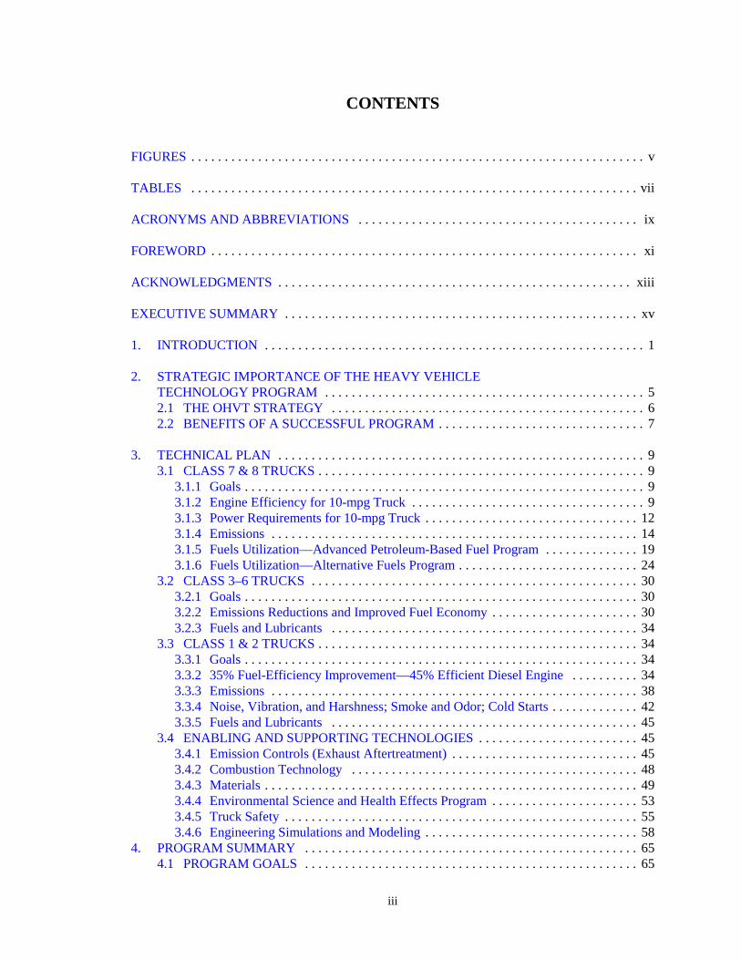
Fig. 1. Trucks account for an increasing amount of highwaytransportation energy use.
of petroleum for transportation, which has maintained a generally upward trend for the lastseveral decades, would start decreasing during the first decade of the next century, as aresult of the development of advanced transportation technologies and increased use ofalternative fuels. Our realization of this vision, through the effective use of domesticresources and products, will immediately reduce our nation’s major concerns relative to thetransportation sector.
Within the transportation sector, the petroleum used by heavy vehicles, especially highwaytrucks, is increasing at a faster rate than that of automobiles. Trucks of all classes use moreenergy than automobiles do (see Fig. 1). 1, 2
Within the DOE Office ofTransportation Technologies (OTT),the Office of Heavy VehicleTechnologies (OHVT) conducts, incollaboration with its heavy vehicleindustry partners and their suppliers,a customer-focused nationalprogram for research anddevelopment (R&D) on criticaltechnologies that will enable theU.S. heavy vehicle transportindustry to fully exploit the energyefficiency and alternative fuelscapability of the diesel engine whilesimultaneously reducing highwayvehicle emissions. The OHVT heavy
vehicle industry customers include truck and bus manufacturers, diesel engine manufacturers,fuel producers, suppliers to these industries, the trucking industry, and other truck users (whomust purchase and use advanced heavy vehicles before energy savings can be realized). Thescope of the OHVT is not limited to on-highway transport. Other modes of transportation arealso recognized to be extremely important. Rail, inland marine, and off-road applications relyprimarily on diesel engines for power, and all are either facing or expecting to face new exhaustemissions regulations in the very near future. Each mode of transport plays a crucial role inmeeting the overall needs of the nation, and there are still ample opportunities to increase energyefficiency, improve social acceptance, and fine-tune the performance of all such systems.
The OHVT collaborated with its industry customers to craft a common industry/governmentvision of the Heavy Vehicle Industry of the Future (see Appendix A for a list of workshops andmeetings at which OHVT representatives met with their colleagues in industry).
The goal of the Heavy Vehicle Technologies Program is to develop by 2004 theenabling technologies needed to achieve an ultra-low emissions, 10 mile-per-gallonClass 7 & 8 truck and to devolve these technologies down through mid-range trucks(Class 3–6) to Class 1 & 2 trucks, achieving at least 35% fuel economy improvementover current gasoline-fueled Class 1-6 trucks.

3
The OHVT Technology Roadmap, prepared in 1996 and published in 1997,2 described anindustry-government R&D partnership in heavy vehicle technologies of common interest, whereexpertise could be shared to achieve the vision for a heavy vehicle industry of the future. Thisrevision to the OHVT Technology Roadmap updates the status of technology, technical targets,barriers, and technical approach to reflect technical progress and changes in regulatory driversmade since the first Roadmap was prepared 3 years ago.


5
Fig. 2. The nation’s economy is linked to efficient heavy vehicletransportation.
2. STRATEGIC IMPORTANCE OF THE HEAVY VEHICLETECHNOLOGY PROGRAM
The Office of Transportation Technologies Strategic Plan 1 addresses the energy, economic,and environmental challenges in meeting the future demand for transportation goods andservices. The Heavy Vehicle Technologies Program is an important component of OTT’sstrategy for achieving its vision because virtually all of the growth in petroleum highway use isdue to heavy vehicles. Heavy vehicles represent a target of opportunity of about 14.3 quads ofhighway transportation energy use by the year 2010 if all trucks and buses are considered(16.0 quads if rail, marine, and off-highway uses are included), assuming that there are nochanges in the current trend in transportation energy use (see Table 1)3,4. Increase in energy useby trucks is due to the growth in demand for transport of goods and products (provided by Class3–8 trucks) as well as the growth in demand for multipurpose vehicles [Class 1 & 2 trucks, whichinclude pickups, vans, and sport-utility vehicles (SUVs)]. Sales of multipurpose vehicles (whichpredominantly use less-efficient gasoline engines) have increased dramatically in the past15 years, from approximately 3 million vehicles in 1983 to 6.8 million in 1997 (from 25% to45%) of the foreign and domestic sales in the United States.5
The health and continued growth of the U.S. economy depends on maintaining the energysecurity and profitability of the trucking industry, now and into the foreseeable future. Trucks arethe mainstay for trade, commerce, and economic growth. The gross domestic product (GDP), andhence, economic activity is directly related to freight transport (see Fig. 2). Therefore, the energydemand for movement of goods is critical to the economy. In addition, the U.S. truckmanufacturing industry represents approximately 1.8 % of the nation’s $8.08 trillion GDP
(1997). In 1996, trucks accountedfor almost $149 billion of the total$284 billion motor vehicle sales.The heavy vehicle industry as awhole (which includes thetrucking industry and other truckusers, truck manufacturers, enginemanufacturers, fuel producers, andcomponent suppliers) will need tomaintain a dominant role inensuring that the U.S. economyremains healthy.

6
Fig. 3. OHVT Program strategy.
Table 1. Targets of opportunity
Vehicle CategoryOil-derived energy (quads)
1995a 2000b 2010b 2020b
Automobiles 8.5 7.7 8.4 9.0
Heavy vehicles (trucks and others) 11.4 13.3 16.0 17.1
Cl. 1–2 trucks (GVW <= 10,000 lb) 5.7 7.2 9.1 9.8
Cl. 3–6 trucks (10,000 < GVW < 26,500 lb) 0.9 0.9 0.8 0.8
Cl. 7–8 trucks (GVW > 26,500 lb) 3.1 3.5 4.2 4.5
Buses 0.2 0.2 0.2 0.2
Rail 0.5 0.5 0.5 0.6
Domestic marine 0.3 0.3 0.4 0.4
Off-highway 0.7 0.7 0.8 0.8
aThe 1995 values are from S. C. Davis, Transportation Energy Data Book, 17th Ed., ORNL 6919, Oak RidgeNational Laboratory, August 1997.
b Projections are from Tables 45 and 46 in U.S. DOE Energy Information Administration, Annual Energy Outlook,1999, DOE EIA-0383 (98), July 1998.
2.1 THE OHVT STRATEGY
The OHVT envisions the development of an energy-efficient, near-zero emissionstechnology, along with safe, energy-efficient, truck-systems technologies as a real and viablestrategy for reducing energy requirements of commercial transport services and the rapidlygrowing multipurpose vehicle market (pickups, vans, and SUVs). The strategy is two-pronged: (1) to improve the efficiency of Class 7 & 8 trucks by developing energy efficient diesel enginesand systems technologies that improve the capability to use alternative fuels while reducing emissions to ultra-low or near-zero levels and (2) to utilize the expertise of the world-class U.S.diesel engine manufacturers in developing highly efficient, ultra-low to near-zero emissionsdiesel engines that will be commercially competitive with gasoline engines in the multipurpose
Class 1 & 2 truck markets,achieving at least a 35% fueleconomy improvement overgasoline-fueled vehicles. Theprogram strategy involves thedevelopment of advancedpetroleum-based fuels as well asalternative, nonpetroleum fuels,and includes R&D on in-cylinder processes and exhaustaftertreatment technologies toenable industry to provide clean,efficient, diesel-powered trucks(see Fig. 3).
7
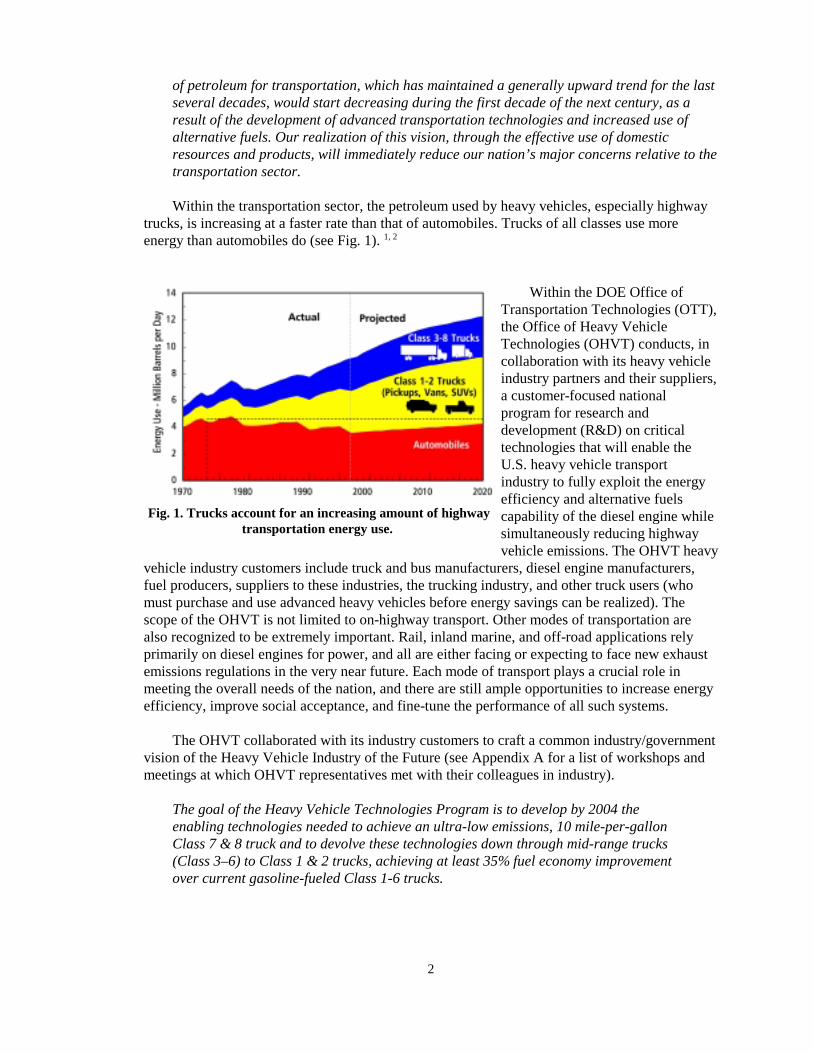
Fig. 4. Heavy-duty diesel truck emissions relative to total on-road emissions. Source: EPA Annual Emissions Trend
Report for 1997.
Fig. 5. Highway petroleum-use reductions from OHVT-supportedtechnologies. (Petroleum use is given in units of 106 barrels/d oil
equivalents.)
Market penetration of energy efficient technologies will depend on the intended use of thetruck. Commercial truck operators will pay a reasonable price for improvements in the fueleconomy of their Class 7 & 8 trucks to improve profitability, whereas fuel economy is lessimportant to buyers of multipurpose Class 1 & 2 trucks (especially those predominantly used forpersonal transportation).
Emissions-control technologies are the key enablers for greater utilization of diesel enginesin medium light-duty vehicles. The inherently higher efficiency diesel engines will requireadvanced emissions control devices if future heavy vehicles are to meet increasingly morestringent U.S. Environmental Protection Agency (EPA) standards. This is the critical requirementfor market entry of more-energy-efficient heavy vehicles beforepotential energy savings can berealized. Although progress has beenmade in reducing heavy-duty dieselemissions in the last 20 years, thepredominantly diesel-poweredheavy-duty transport sector is amajor contributor to criteriapollutant emissions (see Fig. 4).Critical technological breakthroughsare necessary to cost-effectivelymeet EPA standards proposed for theyear 2006 and beyond.
2.2 BENEFITS OF ASUCCESSFUL PROGRAM
Successful implementation of the OHVT technologies outlined in this document is the keyto reducing highway fuel consumption. It will reduce Class 1–8 truck fuel consumption by 1.4million barrels per day oil equivalent (mmb/d oil equivalent) by 2020 and 2.1 million mmb/d by2030, amounting to a reduction of total highway petroleum consumption (including that ofpassenger cars) of 12.6% and 18%, respectively (Fig. 5). The decrease in petroleum consumptionis a result of improvements in truck efficiency as well as increased use of nonpetroleum fuels.
Additional benefits wouldaccrue in the non-roadsectors (rail, pipeline,marine, and off-highwayvehicle), because thesemarkets use enginetechnology common tothe highway truck market.
9
3. TECHNICAL PLAN
3.1 CLASS 7 & 8 TRUCKS
The following sections describe the goals for Class 7 & 8 trucks, the status of technology forthese trucks, the technical targets to be achieved in order to meet these goals, the technicalbarriers that must be overcome to achieve the technical targets, and the technical approach toovercoming those barriers.
3.1.1 Goals
The program goal, with respect to Class 7 & 8 trucks, is to develop by 2004 the enablingtechnology for a truck that will have a fuel efficiency of 10 mpg (at 65 mph), will meetprevailing emission standards, and will use petroleum-based diesel fuel. A separate task willfocus on developing a highly efficient gaseous fuel engine.
The program will achieve this goal by performing the R&D research and developmentrequired to achieve higher engine efficiency, reduced power requirements, reduced emissions,and alternative-fuel capability.
3.1.2 Engine Efficiency for 10-mpg Truck
3.1.2.1 Status of Technology
Compression-ignition (diesel) engines derive their high efficiency from being designed toemulate high-efficiency thermodynamic cycles and to minimize mechanical losses. The basethermal efficiency of diesels comes about from utilizing a relatively high compression:expansionratio, combusting fuel at a high rate. Diesel engines use air-fuel ratio instead of throttling for loadcontrol, thus avoiding the part-load pumping losses characteristic of conventional spark- ignitionengines. Most modern diesels utilize turbocharging, which increases power density and utilizesexhaust heat to a limited extent. They are designed to operate at relatively low speeds, therebymanaging mechanical friction losses. Other design features, like strategic cooling serve tominimize thermal energy losses. Due to their high efficiency, reliability, and availability, dieselengines are the dominant power source for heavy-duty trucks and for city and intercity buses inthe United States and are the preferred power source for commercial surface transportationworldwide. Diesel engines are the most efficient energy-conversion devices available; very largeunits (e.g., land-based and marine engines) exceed 50% thermal efficiency.6 Turbochargeddiesels for highway trucks are now offered that approach 45% efficiency (compared with about

10
Fig. 6. Increasing diesel-cycle engine efficiency.
Fig. 7. Projected contributions of advanced technologiesto diesel engine efficiency improvement to achieve an
increase of 15%.
30% for production gasolineengines), an improvement of about40% relative to diesel engines ofthe late 1970s (see Fig. 6). Thediesel-engine industry believes thatthis number can be increased to50% in the next few years inresearch designs (but not inproduction markets), even withaccelerated implementation ofstricter EPA emissions regulations,which will cause a 5 to 10%reduction in efficiency (see Sect.3.1.4). For example,turbocompounding, essentially an
additional turbocharger shaft coupled to the engine output shaft, is a proven technology forexhaust heat recovery, but it is not widely because it is not cost effective.
3.1.2.2 Technical Targets
A brake thermal efficiency of 50% for the engine has been set as an aggressive butachievable objective. Major diesel engine companies have considered this target and haveconcurred. This target is less ambitious than that in the previous Roadmap because of recentevents that require further emissions reductions in the near term. The “Consent Decree” betweenthe engine manufacturers, U.S. Department of Justice, and the EPA essentially requires that 2004emissions standards be implemented inOctober 2002; it also established newcaps on emissions over a wider rangeof engine operation. To recover the5–10% loss in efficiency and to meetthe emission standards, new exhaustaftertreatment devices will have to bedeveloped.
Further advances in efficiency willbe achieved with improvements incomponents and operatingcharacteristics of engines similar inoverall architecture to those nowwidely used. Contributions of theindividual technical targets to theoverall engine-efficiency goal of 50%are depicted in Fig. 7. A more detailedpresentation of the characteristics ofmodern diesels and the targets andbarriers for advanced technology areshown in Table 2. In addition to improvement to the reciprocator assembly, an effective exhaustheat recovery system is critical to meeting the 50% efficiency target.

11
3.1.2.3 Barriers
The barriers that must be overcome to achieve the component technical targets for the 50%efficient engine are summarized in Table 2. Additionally, emissions standards must be met whileachieving the 50% efficiency goal.
Table 2. Summary of engine-efficiency parameters, technical targets, and barriers critical to 50% efficient engine
Engineparameter
Currentpractice
Technical targetfor 2004
Barrier
Peak cylinderpressure, psi
2000–2200 2800–3500 Structural integrity, thermomechanicalfatigue, friction control, piston/ringlubrication, NOx emissions. Advanced fuel-injection systems and electronic controlcould help decouple NOx and efficiency
Turbochargerefficiency, %
50–58 72–76% withvariable geometryor similarenhancement
Small turbomachinery aerodynamics; rotorinertia; materials for low-mass, aerodynamicrotors
Exhaust heatrecovery
Essentiallynone exceptturbocharger
Recover additional12% of exhaustenergy costeffectively
Cost and complexity of turbo-compounding;efficiency/cost of direct conversion;materials for low-mass, cost-effective rotors;insulation of exhaust system
Brake meaneffectivepressure, psi
200–240 340–400 Structural integrity and thermomechanicalfatigue (see first-row, “peak cylinderpressure”); limitations of single-stageturbochargers; need for adequate boosting.Fuel-injection rate and quantity need bettercontrol
Thermalmanagement
Water and oilcooling,radiator
Selective insulationon piston, ports,head plate.Advanced systemsto reduce parasiticthermal losses
Durable cost-effective coatings and otherthermal barriers; TBC sealing, variablespeed pumps, advanced heat transfer media;hybrid forced-convection/nucleate-boilingsystems and fans would reduce losses
Enginemechanicalfriction
Provide 1% or moreefficiency increase
Piston-ring-liner designs and materials arehigh-friction sources
3.1.2.4 Technical Approach
Specific tasks to improve the efficiency of Class 7 & 8 trucks include the following:
� Define one or more baseline engine designs in sufficient detail to delineate the areas wheretechnology advancement is required. This would serve as a guide for enabling technologyprojects. Conduct, on a continuing basis, analysis and supporting validation tests to assessprogress toward goals.

12
Fig. 8. Distribution of power requirements for atypical Class 8 truck.
� Develop advanced combustion-chamber components for high peak pressures and high brakemean effective pressures, utilizing, as needed, new architectures for components, advancedmaterials, thermal barriers, and novel cooling strategies. Perform materials evaluation tosupport engine design targets, precomponent tests, performance and durability tests of newcomponents, characterization of enabling materials, and finally, tests of complete enginesystems. Identify needs for improved materials as required.
� Develop fuel-injection and combustion technologies that will provide higher peak cylinderpressure for better efficiency without causing higher NOx. Support technology developmentwith modeling and simulation as an integral component of the systems design strategy.Develop and integrate sensors, controls, diagnostics and enabling experimental tools.Emissions aftertreatment may be an approach to allow peak cylinder pressure to be raisedwithout increasing NOx (Sect. 3.1.4 and 3.4.3).
� Develop improved turbocharger and air-handling systems that include variable geometrytechnology, improved rotor aerodynamics, and systems controls. Continue systems analysisto reexamine tradeoffs between turbocharger efficiency and transient response. Review newlow-inertia materials and response-enhancing technologies that may emerge.
� Continue analysis and evaluation of new exhaust heat-recovery technologies as they emerge,including direct energy conversion. Develop materials and designs for improved insulationof exhaust systems. Fabricate and test heat-recovery prototypes that are based on promisingnew technologies.
� Continue development of thermal-barrier designs and enabling materials. Refine analysis ofbenefits of cooling and thermal-barrier strategies and support with experiments. Developeffective thermal-management systems, including novel coolants and circulation systems, toreduce losses.
� Continue refinement of piston/cylinder designs, valve trains, and other mechanicalcomponents for reduced friction losses. Carry out R&D of low-friction materials andlubricants.
3.1.3 Power Requirements for 10-mpg Truck
The realization of 10-mpg trucks willrequire not only improvements in engineefficiency, but also substantial reductionsin the power required to propel the vehicle.This can be achieved by a combination ofreduced aerodynamic drag, reduced rollingresistance, and reduced parasitic losses. Aprevious analysis was reviewed andupdated to identify the key contributors totruck power requirements. 7,8 A steadyhighway speed of 65 mph on level roadswas taken as the base case. The presentsituation for a typical truck is depicted inFig. 8. The steady-state case illustrates thepriority power-consumers, although the

13
value of a lower-weight chassis is less apparent than would be in a variable speed driving cycle.The analysis also highlights just how much fuel economy gain can be attributed to enginedevelopments.
3.1.3.1 Status of Technology
Truck power requirements are dominated by aerodynamic drag, comprising mainly formdrag, surface drag (skin friction), and internal drag (engine compartment and passengerventilation). The combination of these gave large highway trucks a drag coefficient (Cd) of near1.0 for designs of the mid-1970s. Truck cabs with rounded exteriors, plus a combination of airdams, gap seals, and other fairings can reduce the Cd for the tractor-trailer rig to about 0.55.Estimates of fuel economy improvements are 14–19% for combined aerodynamic treatments tothe tractor and trailer. 9
Reduced aerodynamic drag will put increased pressure on an already extended brakingsystem. An improved braking system is therefore an enabling technology.
Rolling resistance is the second-highest factor in truck power requirements. A major shifttoward use of radial tires instead of bias-ply tires has already been made; a low-profile radial tireis in widespread use. The newest generation of tire, the “super single,” offers less rollingresistance. It is an available technology offering fuel savings of a few percent, but there is userresistance for a variety of reasons. Among the concerns is the lack of redundancy in the event ofa failure and the perceptions that road damage is higher. The super singles are also taller thanother radials and thus reduce the freight volume of a closed van trailer. Further, an additionalcost is required to switch from the older systems to the new style. Super single tires are usedprimarily in the niche application of tanker trucks.
3.1.3.2 Targets
The distribution of power requirement comparing a typical Class 8 truck to one withadvanced technology is also shown in Fig. 8. Clearly the greatest gains are achievable byattacking losses due to aerodynamic and rolling resistance. Mechanical losses in gears, bearings,and auxiliaries become more important as the major power drains are reduced. The technicaltargets established to achieve reduced truck power requirements for a 10-mpg truck are given inTable 3. 7–12
3.1.3.3 Barriers
The barriers to achieving the technical targets for reduced truck power requirements aregiven in Table 3. 7-12
3.1.3.4 Technical Approach
Specific tasks to address the power requirements of the 10-mpg truck include the following:
� Update vehicle systems analysis to define fuel-savings benefits of specific technicalstrategies such as aerodynamic designs, weight reduction, tire substitutions, and auxiliariesimprovements.
� Conduct an assessment of the maintenance interferences of aerodynamic aids on vehiclesand conduct competition for operator-friendly designs.

14
� Apply modern computational fluid-dynamics codes to “internal” flows in theradiators/engine compartment and identify new configurations to reduce this element ofaerodynamic drag. Follow analysis with design and experimental verification.
� Develop pneumatic aerodynamic devices to control aerodynamic drag and to increasestability. Design and experimentally verify sensors for actuation of devices.
� Conduct design and tests of lightweight vehicle structures that the systems analysis indicateto be promising.
� Work with the U.S. Department of Transportation and the American Trucking Association(ATA) to conduct further assessments of the issues surrounding use of super single tires.Conduct a defining set of tests on the relative road damage of dual and single tires.
Table 3. Summary of 10-mpg truck parameters, technical targets, and barriers
Vehicleparameter
Currenttechnology
Target Barrier
Aerodynamicdrag
Cd = 0.55 with bestavailable designsand added fairings
Cd = 0.47 (or 15%reduction in widely usedpackages)
Maintenance nuisance, cost ofaero designs.Nonoptimal underhood designs,large radiator
Rolling (tire)frictionlosses
Low-profile radials Reduce rolling resistanceby 8% (assume use ofsuper singles)
Road-damage, stability (safety),and cost concerns for super singletires; availability at truck stops
Mechanicallosses
Transmission andaxles account forup to 7% of powerrequirements
Reduce by 25% Cost-effective alternativematerials and designs
Auxiliaries,parasitics
Shaft-drivenauxiliaries accountfor up to 12% oftruck powerrequirement
Reduce by 25% Cost-effective alternativematerials and designs
3.1.4 Emissions
3.1.4.1 Status of Technology
Reduction in emissions from Class 7 & 8 diesel engines must also be achieved in addition toimprovements in thermal efficiency. When the EPA first began regulating diesel emissions in themid- to late 1970s, trucks typically had emission values of 10–15 g/bhp-h of NOx and 1 g/bhp-hof particulate matter (PM). Over the past 20 years diesel-engine manufacturers have achievedremarkable reductions in NOx and PM emissions by modifying their engines (see Fig. 9).Emissions reductions have been achieved by retarding fuel-injection timing, increasing injection pressures, improving air-handling systems, using oxidation catalysts, and implementing EPA’smandate for low-sulfur diesel fuel (no greater than 0.05% sulfur content) for on-highwayvehicles in the early 1990s. Today's heavy-duty diesel engines are regulated to 4.0 g/bhp-h of

15
YEAR
EPA/CARB2004 (SOP)
1980 1990 20000
2
4
6
8
10
12
14
16
Source: Cummins, modified by DOE
NO
x (g
m/h
p-h
r)
Par
ticul
ates
(gm
/hp-
hr)
1.5
1.0
0.5
NOx
Particulates
1987 ModelsLow indicated mean temperatureShort high ring reversalLow frictionRetard timing
1988 ModelsIncreased injection pressurehigher compression ratioHigher boostRetard timing
1994 Models
ConsentDecree
1991 ModelsIncreased injection pressure
Variable injection timingLow indicated mean temperature/
high indicated mean pressureRetard timing
Fig. 9. Evolution of heavy-duty diesel engine emissions control.
NOx and 0.10 g/bhp-h ofPM (<0.05 g/bhp-h fortransit buses), andsubstantially loweremissions have beenachieved in researchengines.
In spite of thesereductions, there continuesto be concern about theenvironmental and healtheffects of diesel-engineemissions. The CaliforniaAir Resource Board(CARB) has declareddiesel particulate matter to
be a “toxic air contaminant,” and there is widespread uncertainty about the health effects ofdiesel and gasoline emissions within the health-effects community itself. In 1996, the EPA, thestate of California, and major engine manufacturers prepared a Statement of Principles13 (SOP)that required further reduction to 2.4 g/bhp-h of NOx plus non-methane hydrocarbons (NMHC)or 2.5 g/bhp-h of NOx plus NMHC with a maximum of 0.5 g/bhp-h of NMHC by 2004. Recently,an action by the EPA and the U.S. Department of Justice resulted in a consent decree with thediesel-engine manufacturers that moves the SOP requirements to October 2002 and places capson emissions at all operating conditions. The requirement for the diesel-engine manufacturers tomeet these lower emissions standards will result in reduced engine efficiency until new engineand emissions technologies are developed.
Meeting the stringent emission standards set forth in the consent decree while improvingengine efficiency constitutes a major challenge for diesel-engine manufacturers. To address thesechallenges one can consider three approaches: (1) minimizing the pollutants coming out of theengine (engine-out emissions), (2) cleaning the engine emissions to an acceptable level beforeexhausting to the environment (exhaust aftertreatment), and (3) fuel reformulation with orwithout additives.
3.1.4.1.1 Engine-out emissions
Optimizing fuel combustion. Significant reductions in emissions have been made throughcombustion modifications (e.g., retarded injection timing, increased injection pressure, and lowertemperatures); however, further reductions are needed. The key is an improved understanding ofthe diesel combustion and emissions formation processes and the development of design tools(i.e., models) that incorporate the improved understanding and allow engine designers to rapidlyexplore alternative combustion system designs. Much progress has been made in understandingand modeling diesel combustion. However, the level of detailed understanding of themechanisms controlling combustion and emissions that is needed by engine designers to makefurther improvements is not available. Recent work has led to the development of newdiagnostics that are providing this detailed understanding.

16
As new diagnostics advance the understanding of in-cylinder processes in diesel engines,more advanced concepts are being evaluated. A homogeneous-charge, compression ignitiondiesel engine offers the possibility of diesel-like efficiencies with very low engine-out emissions;the challenge is control of the process.
Fuel-injection equipment (FIE) plays a pivotal role in the combustion process. Improvedunderstanding of FIE through modeling and testing and evaluation of performance and durabilityare important in the overall development of reduced engine-out emissions.
Lubricant control. Particle emissions from diesel engines originate from the combustion of lubeoil as well as from combustion of fuel. Although this effect is markedly less, it is nonethelessimportant if the new, more stringent regulations are to be met. Recent studies illustrate themagnitude of the PM contribution from lube oil. A recent study of fuel effects in a light-dutyengine showed that about 5% of the total particle emissions originated from the lube oil, whilethe number was about 10% for a heavy-duty engine.14 However, this value is very engine-specific, and the particle contribution from lube oil can range from a few percent to as much as30% of the total particulate emissions.15 Efforts continue to quantify the effect and to develop themeans to minimize the lube-oil contribution to particulate emissions while maintaining adequateengine lubrication.
3.1.4.1.2 Exhaust aftertreatment
Several concepts are being pursued that could potentially affect both NOx and particles butmost still require significant development before they could be considered ready for commercialuse.
Lean-burn catalysts. Catalytic systems in today’s automobiles operate with air:fuel ratios at orclose to stoichiometric. In such systems, both reduction of NOx and oxidation of carbonmonoxide (CO) and hydrocarbon (particles) can be accomplished in a single catalyst bed;sufficient reducing gases are present to reduce NOx, and enough oxygen is available to oxidizethe CO and hydrocarbons. However, because diesel engines operate under lean-fuel conditions(i.e., excess oxygen), conventional catalysts are not effective; therefore, new catalysts arerequired. This is an active area of R&D in which many promising ideas are being pursued byengine manufacturers around the world. NOx conversion efficiency with these systems ispresently inadequate for most emissions targets.
Plasma systems. In plasma systems, short electrical discharges are used to create a plasma thatcontains electrons, ions, and radicals that are used to reduce NOx and oxidize hydrocarbons.However, such systems working alone have been found to be energy intensive and primarilyoxidative and, therefore, not attractive for NOx reduction. Plasma-assisted catalysis offers thepotential of enhanced performance over unassisted lean-NOx catalysis. Potential benefits includemore efficient (80%) NOx reduction, a much broader operating temperature range, and less needfor noble metals.
Particle traps. For commercial use a particle filter must (1) filter carbon particles from ahigh-temperature diesel exhaust gas at an acceptable backpressure; (2) survive thousands ofthermal transients due to regeneration or cleaning of the filter by oxidizing the collected carbon;(3) be durable and reliable over the life of the filter which is in excess of 300,000 miles(10,000 h); and (4) provide a low overall operating cost that is competitive with other filteringtechniques. State-of-the-art systems for filtering carbon particles and regenerating the trap have a

17
few remaining shortcomings. Particle filters are costly and result in modest fuel-consumptionpenalties. Their regeneration requires catalytic systems that are sensitive to sulfur in somedesigns. Other catalytic soot filters still require regeneration temperatures that may be too highfor some applications.
An alternative aftertreatment for particles is the use of plasma devices (see previoussection), which have shown great potential for particle destruction in preliminary tests.
NOx absorbers. Absorber materials are being developed to reduce NOx under lean exhaustconditions. These materials would be regenerated (i.e., they would reduce the NOx) by a pulse ofhydrocarbons introduced into the exhaust system. While effective with ultra-low-sulfur fuels, thecurrent fuel sulfur levels significantly reduce the absorption capacity of current materials. R&Dis required to develop materials that are less sensitive to sulfur, exhibit high NOx absorptioncapacity and regenerative capacity over the expected exhaust-temperature range and life of thetruck. The regeneration requires a near-oxygen-free environment in the exhaust for short periods,which is a major engineering and control-system challenge.
Selective Catalyst Reduction (SCR). Selective catalyst reduction materials effectively reduceNOx over a catalyst bed in the presence of a reducing agent that is added to the exhaust system incontrolled amounts. R&D is needed to reduce the sensitivity of the catalyst materials to sulfurand to evaluate their performance at expected operating conditions over the life of the truck.Because of the lean diesel-exhaust environment, both NOx absorbers and SCR materials requirethe addition of a reducing agent. Further research is needed to define the addition and control ofreducing agents added to the exhaust system. The infrastructure needed to distribute the SCRreagent (e.g., urea) is a major impediment.
3.1.4.1.3 Fuel reformulations and additives
To reach the goal of lower emissions while maintaining efficiency, fuel quality standardsmust remain high. Fuel reformulations and additives can lead to lower exhaust emissions, betterfuel economy, and improved cold start performance. Additives can also be used to improvelubricity in low-sulfur fuels. Efforts are under way to understand the effectiveness of differentadditives and to determine how their use can be optimized (see Sect. 3.1.5 for more detaileddiscussion of fuels and lubricants).
3.1.4.2 Technical Targets
The emissions targets are as follows: 0.01 g/bhp-h PM and 2.4 g/bhp-h of NOx plus NMHCor 2.5 g/bhp-h of NOx plus NMHC with a maximum of 0.5 g/bhp-h of NMHC or less by October2002, while achieving the efficiency goals. The program has developed strict emissions targets of1.0 g/bhp/h NOx and 0.05 g/bhp/h PM for 2006 (see Table 4).
3.1.4.3 Barriers
The barriers to achieving the technical targets for emissions from diesel engines for Class7 & 8 trucks are given in Table 4.
18
Fig. 10. Multifaceted emission-controlapproach necessary to ensure that fuel-
economy, cost, and durability goals are inharmony with ambitious emission targets.
Table 4. Summary of goals, technical targets, and barriers for Class 7 & 8 emissions
Goals Technical targets Barriers
Minimizeengine-outemissions
By 2002: 0.1 g/bhp-h PM2.4 g/bhp-h NOx + NMHC or0.1 g/bhp-h PM2.5 g/bhp-h NOx + NMHC withmaximum of 0.5 g/bhp-h NMHC
NOx/PM trade-off; that is, maintainingefficiency and keeping PM down.Meeting the target across the load andspeed map. Reliability. Limitations oncost-effective fuel additives andreformulation
Developeffectiveaftertreatment
By 2006:1.0 g/bhp-h NOx and 0.05 g/bhp-h PM
Development of lean combustion catalyst.Cost effectiveness. Durability/reliability
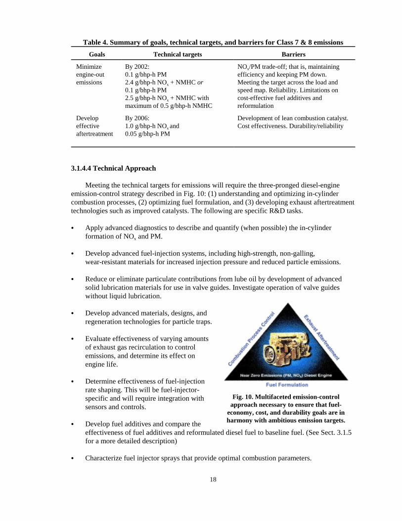
3.1.4.4 Technical Approach
Meeting the technical targets for emissions will require the three-pronged diesel-engineemission-control strategy described in Fig. 10: (1) understanding and optimizing in-cylindercombustion processes, (2) optimizing fuel formulation, and (3) developing exhaust aftertreatmenttechnologies such as improved catalysts. The following are specific R&D tasks.
� Apply advanced diagnostics to describe and quantify (when possible) the in-cylinderformation of NOx and PM.
� Develop advanced fuel-injection systems, including high-strength, non-galling,wear-resistant materials for increased injection pressure and reduced particle emissions.
� Reduce or eliminate particulate contributions from lube oil by development of advancedsolid lubrication materials for use in valve guides. Investigate operation of valve guideswithout liquid lubrication.
� Develop advanced materials, designs, andregeneration technologies for particle traps.
� Evaluate effectiveness of varying amountsof exhaust gas recirculation to controlemissions, and determine its effect onengine life.
� Determine effectiveness of fuel-injectionrate shaping. This will be fuel-injector-specific and will require integration withsensors and controls.
� Develop fuel additives and compare theeffectiveness of fuel additives and reformulated diesel fuel to baseline fuel. (See Sect. 3.1.5for a more detailed description)
� Characterize fuel injector sprays that provide optimal combustion parameters.

19
� Formulate new, cost-effective catalysts and systems that reduce NOx in lean combustionenvironments. This task includes investigation of SCR catalysts and NOx adsorbers.
� Evaluate effective catalyst formulations for longevity and stability to meet 300,000-milerequirement.
� Evaluate plasma-assisted catalysis at high flow rates of diesel-engine exhaust.
� Conduct experimental and modeling program to form a better understanding of the chemicaland physical mechanisms of plasma-assisted catalysis.
3.1.5 Fuels Utilization—Advanced Petroleum-Based Fuel Program
The OHVT program strategy focuses on improving the performance of diesel engines andreducing their emissions by using either advanced petroleum-based (APB) fuels or liquid orgaseous alternative fuels. Therefore, fuels and lubricants R&D activities are divided into twoprograms: the Advanced Petroleum-Based Fuels Program and the Alternative Fuels Program.
To enable the development of ultra-low-emission vehicles, the Advanced Petroleum-BasedFuels Program includes reformulation of diesel fuels and lubricants derived from crude oil. Theprogram aims to develop pragmatic, near-term solutions for improving thermal efficiency ofdiesel engines and reducing their emissions. It includes research on blendstocks and additivesused to upgrade or extend diesel-base fuels. A multiyear program plan16 has been developedjointly by the DOE Office of Advanced Automotive Technologies, DOE-OHVT, industryrepresentatives, research partners, and other stakeholders.
The Alternative Fuels Program is focused primarily on natural gas and Fischer-Tropsch(F-T) synthetic diesel produced from natural gas and biomass feedstocks, but also includesresearch on fuels of the future. To successfully achieve DOE-OTT goals to reduce the nation’sreliance on imported oil and promote energy diversity, it is important for alternative fuels to beused in heavy vehicles. This section discusses the possibility of using these alternative fuels inheavy trucks and buses and some of the barriers that must be overcome. Each of the medium- andheavy-duty engine manufacturers offers production engines designed to operate on alternativefuels. Cooperative industry and government projects will be established to optimize fuelformulations and engine system technologies concurrently.
3.1.5.1 Status of Technology
Since 1990, the EPA has required that all diesel fuel sold for use in on-road vehicles haveno greater than 500-ppm sulfur content (the resulting average is about 340 ppm). In addition, itmust meet the limits of either a maximum aromatic content of 35% or a minimum cetane numberof 40. Since 1993, CARB has required that in addition to limiting sulfur content to 500 ppm,diesel fuel sold in California for both on-road and off-road diesel vehicles must have a maximumof 10% aromatic content (20% for small refiners; alternative formulations with higher aromaticcontent are allowable if they are proven to produce the same or lower emissions). These limits ondiesel fuel properties are intended to reduce emissions of NOx and PM.

20
Much of the diesel fuel research to date has focused on higher cetane number, lower sulfurcontent, and lower aromatic content to reduce engine exhaust emissions. However, the blendingof other fuel components, such as oxygenates or paraffins, in diesel fuel can also dramaticallyreduce engine emissions. Biodiesel, methylal, and F-T synthetics are all effective blendstocks fordiesel-based fuels; 20 to 60% reductions in engine-out PM are possible based on laboratorytesting in a variety of unmodified engines. Researchers have concluded that significantengine-out emission reductions are possible through modifications of diesel fuel propertiesbeyond those mandated to date by EPA and CARB.
Further reducing the sulfur content of diesel fuel to 30 ppm or lower has the potential toenable several emission-control/aftertreatment devices that could significantly lower NOx andparticulate emissions. Additional fuel modifications have the potential to further lowerengine-out emissions and make these emission control devices more effective, less costly, orboth. The Diesel Emission Controls and Sulfur Effects (DECSE) project, a cooperative researcheffort between the OHVT, Engine Manufacturers Association (EMA), and Manufacturers ofEmission Controls Association (MECA), is underway to study the effect of sulfur content onaftertreatment system performance.
3.1.5.2 Technical Targets
Technical targets are outlined in Table 5 and are more extensively defined in the DOE-OAAT/OHVT Advanced Petroleum-Based Fuels (APB) R&D Multiyear Program Plan.16
Technical targets for the APB Fuels Program have been established to enable achievementof the overall emissions and efficiency goals set by the OHVT engine development programareas. Research on this program will (1) assist in achieving emission reductions to meetnear-term emission standards, (2) determine relationships between fuel properties and emissionsfor future mid-term enhancements of fuels, and (3) provide a foundation for longer-termdevelopment of new fuels. Advanced petroleum-based fuels not only will enable this engine classto meet future emissions standards, but also will provide opportunities for substantialimprovements in energy efficiency and reductions in greenhouse-gas emissions.
Separate technical targets are listed for engines without aftertreatment (engine-outemissions) and for engines equipped with aftertreatment/emission controls (post-aftertreatmentor “tailpipe-out” emissions). Several technical approaches are possible to meet future emissionsregulations, depending on the stringency of the engine application, the stringency of theemissions standard, the incremental fuel cost, the incremental vehicle cost, and the service lifeexpectation.
3.1.5.3 Barriers
Technical barriers to the development and implementation of advanced petroleum-basedfuels for next generation of diesel engines and emission control systems are described in thefollowing paragraphs. These barriers are listed without regard to their relative severity orprogram emphasis.
� Fuel property effects on emissions and efficiency: Data and models correlating fuelproperties to engine-out emissions and efficiency are limited in scope and have unexplaineddifferences among various engine types. Emissions and efficiency tradeoffs may besubstantially different for new fuels, especially if engines are equipped with emission-control devices.

Table 5. Summary of technical targets and barriers for advanced petroleum-based fuels for medium & heavy-duty applications
Attribute Current practice Target Barrier
Fuel cost Retail price of conventional on-roaddiesel is about $1.00/gal
Incremental price of reformulateddiesel <$0.05/gal or <5%
Production economics, retooling refineries, infrastructure costs, health,safety, and regulatory costs especially for nonpetroleum blendstocks andadditives
Engineefficiency
46% peak thermal efficiency in truckengines
50% peak thermal efficiency by2004
NOx-efficiency trade-off, fuel reformulation to enable durable, active NOx
emissions controls and advanced injection timing
Engineemissions
EPA 2004 on-highway truck, standardsrequired to be met by October 2002 (onlyrequired for 95% of diesel engines)
NOx+ NMHC=2.5 g/bhp-hPM=0.1 g/bhp-h (trucks)PM=0.05 g/bhp-h (buses)
Engine-out:NOx+NMHC<2.4 g/bhp-hPM < 0.1 g/bhp-hby 2002
With aftertreatment:By 2006, 50% NOx reductioncompared to Diesel No. 2 withoutafter-treatment and75% PM reduction.Research targets:1.0 g/bhp-h NOx
0.0125 g/bhp-h PM
Engine out: NOx-efficiency tradeoff, lube oil contributions, toxic emissionsfor non-petroleum blendstocks and additives
With aftertreatment: fuel sulfur content, fuel reformulation to enabledurable NOx and PM emissions controls, fuel additives for catalyst/filterregeneration, toxic emissions for non-petroleum blendstocks and additives,optimization for emissions controls, emission-control system deteriorationand service life.Also: EGR, lack of standard test procedures for emissions controls, ultrafineparticle emissions
Enginereliability
Emissions certified to 435,000 milesequivalent, plus customer expectation formillion-mile truck engine (before firstmajor overhaul)
Engine durability equivalent to thatof engines using diesel No. 2
Concerns about service life of emission controls and effect of lube oilreformulation, fuel lubricity, and EGR on engine durability
21

22
� Emission system degradation: Knowledge is limited of how fuel properties affect engine-outemissions, the deterioration rates of emission aftertreatment devices, and the durability ofemission control components.
� Effect of sulfur: Sulfur from the fuel and consumed lubricating oil poisons and rapidlyrenders ineffective many aftertreatment devices and reduces the durability of other systemssuch as cooled exhaust gas recirculation (EGR) systems. Data are lacking on the magnitudeof the impacts and on reversibility following exposure to fuels with high sulfur levels.
� Ultrafine particles: Diesel engines may be significant contributors to the existing ambientinventory of ultrafine particles in the atmosphere, and the study of the measurement ofultrafine particles (i.e., particles of diameter < 0.1 �m) is just beginning. The formationmechanism of ultrafine particles is related, among other things, to how exhaust gases arediluted with the air. Likewise, the role of aftertreatment devices on formation of ultrafineparticles is not well defined, but oxidation catalysts have been shown to cause increases inthe number of ultrafine particles while reducing the mass of particulate emissions. The lackof knowledge in these areas may inhibit the development of advanced petroleum-basedfuels that could significantly reduce ultrafine particulate emissions from diesel engines.
� Toxic emissions: Data are limited on the emissions and human-health impacts of petroleumbased-fuel and nonpetroleum components on emission of toxics as defined by the Clean AirAct amendments of 1990. Emissions of additional compounds that could be consideredtoxic are coming under increasing scrutiny by regulators. The lack of data about toxicemissions from existing fuels and engines is a barrier to determining desirablecharacteristics of advanced petroleum-based fuels and any nonpetroleum fuel components.Thus the benefits of various fuel formulation and engine/emission system control optionscannot be determined at this time.
� Engine durability: Use of alternative fuels or advanced/reformulated petroleum-based fuelsmay necessitate the use of new fuel additives to enhance lubricity and elastomercompatibility.
� Advanced fuel production and costs: Data on refinery economics and processing strategiesare insufficient to compare options for advanced petroleum-based fuels. Nonpetroleum fuelcomponents typically have preliminary or proprietary production economic data.Insufficient advanced-fuel production and cost data are barriers to making informeddecisions about the commercial viability of advanced petroleum-based diesel fuels.
� Health, safety, and regulatory issues: Data pertaining to health, safety, and regulatory issuesfor most nonpetroleum fuel components are sparse or incomplete. Without knowledge ofthese issues, it is difficult to screen out those components with undesirable characteristics.This lack of information raises a barrier to investigation of potential nonpetroleum fuelcomponents that could have substantial emissions and energy efficiency benefits. Shoulddesirable advanced fuels have health, safety, or regulatory issues, the issues will need to beresolved to the extent required by regulatory bodies to allow their sale and use in motorvehicles (see Sect. 3.4.4 for description of research related to this issue).
� Infrastructure impacts: Little is known about the technical and economic impacts ofnonpetroleum fuel components of advanced petroleum-based fuels on the distribution,

23
storage, and retailing infrastructure. If the characteristics of nonpetroleum fuel componentswere to cause compatibility or fungibility problems with the diesel-based fuel, barrierswould be raised to their widespread use. Advanced petroleum-based fuels will not besuccessful commercially unless they can be distributed, stored, and sold in a manner thatmeets regulations and is acceptable to consumers.
3.1.5.4 Technical Approach
An integrated technical approach has been developed to address the barriers and to meet thetechnical targets in the 2000–2004 time period. The technical approach summarized in thissection is comprehensively presented in the DOE OAAT/OHVT Advanced Petroleum-BasedFuels R&D Multiyear Program Plan.16
The technical approach comprises the following integrated work elements:
� Fuels screening. Potential constituents of an advanced petroleum-based fuel for dieselengines will be screened and assessed according to three principal factors prior to extensiveengine testing under the program: (1) general combustion characteristics, (2) safety andhealth properties, and (3) production and distribution issues.
� Fuel and lubricant property testing for reduced engine-out emissions. Engine laboratorytests will be performed to study efficiency and emissions tradeoffs. In addition, the effect oflube oil as an emission-control containment will be evaluated.
� Fuel and lubricant property testing to enable emission controls. Engine laboratory tests willbe performed to evaluate fuel and aftertreatment device combinations and to studyefficiency and emissions tradeoffs.
� Potential for higher efficiency and reduced emissions. Empirical models will be generatedfrom test data collected during the fuel and lubricant testing to reduce engine-out emissionsand to enable emission controls. The models will be validated by comparison with test dataand will be used to identify promising fuel formulations and emission control-options froma technical perspective.
� Refinery and fuel processing economics. The potential economic viability of advancedpetroleum-based fuels and fuel components will be studied.
� Infrastructure. The compatibility of advanced petroleum-based fuels and nonpetroleum fuelcomponents with the current infrastructure for producing, transporting, and storing fuelswill be studied.
� Vehicle performance. The compatibility and durability of the vehicle fuel system, engine,and emission-control system will be investigated for promising fuels. Fleet tests will beused to evaluate the “real-world” performance of advanced petroleum-based fuels.
� Safety, health, and consumer acceptance aspects of advanced fuels. Health risks, safetyrisks, environmental risks, and perceived odor issues will be assessed.

24
� Assessment of fuel options. The results from the work elements will be used to evaluate fueloptions. Limited program resources will be expended to provide guidance to DOE and itsindustry collaborators on the relative merits of advanced diesel fuel options.
3.1.6 Fuels Utilization—Alternative Fuels Program
3.1.6.1 Status of Technology
Alternative fuels can displace diesel fuel in Class 7 & 8 truck and bus applications.Biodiesel and synthetic diesel fuel may be used in unmodified or slightly modified engines andvehicles. However, most other alternative fuels cannot be used directly in unmodified vehicles,but rather require substantial engine and vehicle modifications. Technical and infrastructurebarriers are associated with alcohol and gaseous fuels, and these barriers lessen the widespreaddeployment and utilization of alternative-fuel vehicles.
To maximize performance and reduce emissions from alternative-fuel vehicles, engine andvehicle systems must be optimized for each type of fuel. Alternative fuels for use in unmodifiedor fuel-flexible engines may be desirable for certain applications and markets but may result incompromised performance and emissions, thereby not fully exploiting the attributes of cleaneralternative fuels.
Substantial progress has been made for the following alternative fuels:
� Fischer-Tropsch (F-T) Diesel Fuel— Commercial-scale production plants are producing synthetic gasoline and diesel fuel in
South Africa. Neat synthetic diesel fuels have been used to fuel unmodified heavycommercial vehicles.
— In the United States, F-T diesel was tested in unmodified Class 8 trucks and transit buseswith no detectable performance difference compared with conventional diesel fuel.Substitution of F-T diesel resulted in a 10 to 15% NOx reduction and about a 25% PMreduction.
— F-T diesel has been used as a commercial-scale blendstock to upgrade diesel fuel to meetCalifornia diesel fuel standards.
� Gaseous Fuels (natural gas and propane)— Vehicle emissions tests indicate that NOx emissions are typically 50% lower and PM
emissions are typically 90% lower than with diesel fuel. Overall efficiency for theseengines is approximately 10 to 15% lower than with diesel fuel.
— Cummins, DDC, Deere, and Mack offer dedicated homogenous-charge, spark-ignited,natural gas engines for Class 7 & 8 vehicles. Cummins is discontinuing the L10G naturalgas engine product due to disappointing sales.
— Compressed natural gas (CNG) transit buses are proven in service, now accounting forabout 25% of new bus orders in the United States.
— Customers have requested higher-power natural gas (NG) engines for Class 8applications. Mack is developing a 400-hp dedicated NG engine for the Class 7 & 8truck market. Caterpillar, in collaboration with Clean Air Partners (CAPS), offers C12dual-fuel engines rated at 400 hp.
— Cummins offers a propane engine (the B5.9-LPG), but commercial sales have beenbelow expectations.

25
— Stratified-charge, direct-injection natural gas (DING) and micro-pilot fuel systems arebeing developed in the engine laboratory to overcome part-load efficiency barriers.
� Alcohols— In the United States, highly modified direct-injection (DI) diesel engines with high-
compression ratios and glow-plugs were developed to combust low-cetane alcohols.Near-diesel efficiency was achieved. DDC 6V-92 alcohol engines were tested in trucksand buses and were sold commercially with mixed results.
— European manufacturers are actively introducing alcohol-powered vehicles equippedwith diesel-like engines. These engines require a fuel additive to improve the cetanenumber and enable autoignition of the fuel.
� Future Fuels (Toxicity data will be collected and evaluated prior to any recommendedintroduction of future fuels.)— Biodiesel. Essentially no major engine changes are required; normal diesel-cycle engine
operation has been demonstrated. Diesel-like efficiency and substantial PM reductionshave been measured on a variety of engines.
— Dimethyl Ether (DME). Direct injection of DME requires extensive changes to the fueldelivery and injection systems. Nearly soot-free combustion and efficiency near or equalto diesel fuel has been demonstrated in the laboratory.
— Dimethoxy Methane (DMM, Methylal). DMM is less volatile than DME but morevolatile than diesel fuel. DMM has been successfully tested in unmodified engines in thelaboratory; very low particulate emissions have been demonstrated.
— Diethyl Ether (DEE). DEE is a renewable pathway for oxygenating diesel from thebiomass ethanol process. Based on preliminary engine testing, DEE is not as effective asDME and DMM for reducing PM emissions when blended with diesel.
The Alternative Fuels Program R&D efforts continue to focus mostly on F-T syntheticdiesel fuel and natural gas. These priorities are in agreement with findings from theOAAT/OHVT Fuels Plan, and research pathways are consistent with the DOE-OHVTGovernment Performance and Results Act (GPRA) Performance-Based Management process.
Over the past two years, the DOE has been actively evaluating F-T fuel for use in dieselengines. Laboratory research and vehicle tests indicate that F-T diesel can be safely substitutedfor diesel fuel without significant performance loss. Substantial NOx and PM reductions havealso been measured in a variety of emissions laboratories. Still further emissions reductions maybe realized if engine systems are optimized for use with F-T diesel. F-T diesel may also enablethe use of sulfur-intolerant aftertreatment and emission-control devices. Additive packages toimprove cold-flow and lubricity properties are under development.
Most alternative-fuel heavy-duty engines being offered today run on natural gas. Theseengines are primarily used in city buses, school and shuttle buses, refuse haulers, and centrallyfueled truck fleets. The following two approaches are being used in production engines today.
� Spark-ignited natural gas (SING) engines. These engines are usually based on a dieselengine block but are converted to spark ignition. Cummins, Detroit Diesel, Deere, and Mackhave homogeneous charge, throttle-body injection engines in production. All of theseproduction engines use a lean-burn strategy for better fuel economy. At full load, the lean-burn spark-ignition engines reach near-diesel efficiency; however, at idle and part-load

26
conditions, their efficiency is significantly less than that of a diesel engine. Very lowvehicle emissions have been demonstrated in the laboratory and in service. The Deere 8.1-liter natural gas engine developed for the Ultra-Safe Ultra-Low Emission Blue Bird SchoolBus has demonstrated 1.0 g/bhp-h NOx, less than 0.03 g/bhp-h PM, and 40% peak thermalefficiency, perhaps the best available benchmark for future technology comparisons.
� Dual-fuel natural gas (DFNG) engines. These engines can be run on diesel only but cannotbe run on natural gas only because the autoignition characteristics of natural gas are poor.At idle and low load conditions they burn mostly diesel fuel. At full load, a small pilotinjection of diesel fuel is used to ignite the main charge of natural gas; over the full cycle,the engines burn up to 95% natural gas. Caterpillar, in collaboration with CAPS, hasdeveloped a full line of heavy-duty DFNG engines that are finding applications inCalifornia. Westport Innovations is collaborating with Cummins and DDC to develop dual-fuel DI fuel systems for the Signature 600 and 6V-92 engines, respectively. Themanufacturers claim that these engines overcome part-load thermal-efficiency penaltiesassociated with dedicated natural gas engines, while maintaining diesel-like rated power.Preliminary chassis dynamometer tests indicate that the Caterpillar/CAPS dual-fuel vehicleemissions are lower than diesel vehicles but are substantially higher than dedicated SING-powered vehicles.
DI natural gas fuel-injection systems and diesel micropilot fuel-injection systems are beingdeveloped in the research laboratories to overcome part-load inefficiencies associated with theSING engines and to further reduce engine-out emissions.
Natural gas is currently stored either as a CNG at pressures up to 3600 psi or as liquefiednatural gas (LNG), a cryogenic liquid, on board heavy vehicles. Development of high-pressuretanks has resulted in lighter tanks in the past few years, and efforts are under way to lower thecost of these tanks. DOE sponsors work on developing effective adsorption media to storenatural gas at low pressures. LNG is the preferred fuel storage technology for Class 7 & 8applications because these vehicle applications require greater range. The availability andreliability of refueling stations must be improved to facilitate more widespread deployment ofnatural gas vehicles.
3.1.6.2 Technical Targets
The technical targets for the Alternative Fuels Program are outlined in Tables 6 and 7. Thefollowing are the primary targets:
� For a liquid alternative fuel such as F-T synthetic diesel, less than 2.2 g/bhp-h engine-outNOx emissions and less than 0.05 g/bhp-h PM by 2004, and peak thermal efficiency over50% by 2006.
� For dedicated gaseous-fuel engines, less than 1.0 g/bhp-h NOx emissions, improved part-load thermal efficiency and peak thermal efficiency over 45% by 2004.

Table 6. Summary of technical targets and barriers for Class 7 & 8 Fischer-Tropsch-fueled diesel engine
Parameters Current practice Target Barrier
Cost F-T has been used as a blendstock to meetCalifornia diesel fuel standards and is used asa neat-fuel in South Africa
Same as engine optimized forultra-low sulfur diesel fuel
Fuel supply and distribution infrastructure issues. Acceptance by marketplace of any cost penalty
Efficiency Same as diesel on an energy-equivalent basis 50% peak thermal efficiency by2006
Same barriers as for a high efficiency diesel engine, plus optimumcompression ratio, injection timing, and EGR rate are different for F-T fuels
Emissions EPA 2004 on-highway truck standards:NOx + NMHC = 2.5 g/bhp-hNOx = 2.4 g/bhp-hPM = 0.1 g/bhp-h
Engine-out:NOx < 2.2 g/bhp-hPM < 0.05 g/bhp-h by
2004
NOx-efficiency tradeoff and possible adaptation of NOx-reductionaftertreatment devices. Optimum EGR rate may be different for F-T fuels
Reliability Similar to or same as diesel Same as diesel Possible concerns about cold-flow properties, seal compatibility, andlubricity
Table 7. Summary of technical targets and barriers for Classes 7 & 8 dedicated gaseous-fuel engine
Parameters Current practice Target Barrier
Cost 15 to 100% more than a diesel engine Same as diesel engine Current production volumes are low. Fuel storage system costs are high.Added components and complexity add cost
Efficiency Maximum of 40% with lean-burn SING, 15%less efficient than diesel in the field withSING engines, 4% less than diesel with pilotignition natural gas
>45% peak thermal efficiencyby 2004
Same barriers as for a high-efficiency diesel engine, plus low cetane ratingof fuel makes diesel cycle difficult. May need low-cost sensors for knockdetection and ignition system improvements
Emissions Dedicated lean-burn NG spark ignited engine:NOx = 1/4 g/bhp-hNMHC = 0.5 g/bhp-hCO = 6.0 g/bhp-hPM < 0.05 g/bhp-h
NOx < 1.0 g/bhp-hPM < 0.03 g/bhp-h
Maintaining low emissions while increasing efficiency
Reliability Similar to diesel Same as diesel Spark plug life (if SI), fuel delivery system reliability, valve/valve seat wear
27

28
Both emissions targets are for the U.S. EPA federal test procedure (FTP) transient test cycleand are significantly lower than the 2004 on-highway emissions standards that enginemanufacturers must now meet by October 2002 as a result of the Consent Decree with the EPA.
Recent laboratory tests show that F-T diesel fuels have the potential to reduce NOx
emissions by 10 to 15% in unmodified engines without significant changes in fuel energyconsumption. Since F-T diesel is also sulfur-free, it enables the use of sulfur-intolerant NOx
aftertreatment devices, such as NOx adsorbers and lean NOx catalysts.
Laboratory research has shown that direct injection of natural gas is feasible and can lead tolow NOx emissions with diesel-like thermal efficiency. The Caterpillar DING system hasachieved 2.5 g/bhp-h NOx and 40% peak thermal efficiency, but requires the use of EGR. Moreadvancements are needed to meet this target, and two laboratory research projects are under way.The direct-injection stratified charge fuel system developed by Deere and the SouthwestResearch Institute (SwRI) allows very lean engine fueling overall.
Micro-pilot injection, which uses a pilot charge of diesel fuel to ignite the main charge ofnatural gas, is also being tested on a single-cylinder engine in the research laboratory. Both ofthese technologies show promise for meeting this target.
3.1.6.3 Barriers
Barriers to deploying F-T-fueled and gaseous-fueled engines are given in Tables 6 and 7,respectively. The primary barrier is probably a market barrier and not a technical one. Because oftheir additional cost and complexity, an incentive such as lower alternative-fuel cost or perceivedthreat of a fuel shortage will be required to create a market for alternative-fuel engines.
The primary barriers for F-T diesel are economic. Fuel production facilities would need tobe constructed and would be most attractive where large quantities of inexpensive natural gas areavailable. In such locations, which are usually remote, capital costs for production facilityconstruction would be high because of a lack of general infrastructure (e.g., roads). Additionally,if F-T diesel (or a blend) were marketed at the same time as other grades of diesel, it wouldpresumably be necessary to segregate types of diesel fuel to some extent. Minimally, additionaltankage would be required at fueling stations. Also, fungibility of the F-T diesel for pipelinetransport has not been verified.
For natural gas vehicles, technical barriers pertain more to vehicle fuel storage and refuelingstations rather than with the engine. The weight of the vehicle resulting from the extracomponents required on the engine as well as additional fuel tanks can be a barrier. Any increasein weight reduces load-carrying capacity. If extra fuel tanks are required, the space availabilityon the vehicle for the extra tanks can also be a barrier. Insufficient fueling infrastructure andunreliable fueling stations are also barriers to gaseous fuel use.
3.1.6.4 Technical Approach
Technical Approach for the Fischer-Tropsch diesel engine. Unmodified diesel engines can beoperated on F-T diesel; however, there are no commercially available engines optimized for usewith F-T or other liquid alternative fuels. This program will support the research needed to
29
develop an engine optimized for F-T diesel and will address the technical barriers to developinga commercially viable liquid alternative fuel truck. The following are specific elements of thetechnical approach to overcoming the barriers outlined in Table 6.
� Conduct basic research on F-T diesel fuel to better understand the combustion process.
� Support R&D targeted at creating a high-efficiency engine optimized for use with F-Tdiesel fuel. Examine emissions and efficiency tradeoffs.
� Reduce exhaust emissions by optimizing injection-timing events, lowering combustiontemperature, using EGR, and developing lean NOx aftertreatment devices.
� Investigate low-cost additive packages for F-T fuels.
� Make low cost a priority on all development projects. Identify technologies that overcomethe other barriers at the lowest cost.
Technical Approach for the gaseous-fuel engine. Gaseous-fuel truck and bus engines are nowavailable and proven; however, most of these engines are more costly and have significantlylower part-load efficiency than comparable diesel engines. The Alternative Fuels Program willfocus on improving the efficiency of these engines, thereby reducing the operating cost. Theprogram will aim to develop Class 7 & 8 LNG trucks and Class 7 & 8 CNG/LNG buses that arefully comparable in cost and performance with their diesel counterparts. The following arespecific elements of the technical approach to overcoming the barriers outlined in Table 7.
� R&D targeted at improving the efficiency of dedicated gaseous-fuel engines. Work mayinclude extending the lean limit, developing advanced control systems, and developingdirect injection, micro-pilot injection, variable valve timing, skip firing, Miller cycle,17 orother strategies.
� Development of sensors or other technology to detect fuel-quality variations and to adaptthe engine controls to extend the lean limit.
� Development of durable, low-cost ignition systems, addressing emissions impacts with eachdevelopment step.
� Development of durable, wear- and corrosion-resistant intake valves, valve seats, and valveguides to increase durability of natural gas engines.
� Development of safe, lightweight, fuel tanks and fuel-storage media.
� Research aimed at expanding fueling infrastructure and improving performance of existingLNG and CNG refueling stations. Pursue research on such technologies as leakless,freeze-resistant nozzles, odorization of LNG, improved cryogenic pumps and safebreakaway hoses. Also, continue work on broadening LNG supply by supporting R&D oninnovative, small-scale liquefaction technologies.

30
3.2 CLASS 3–6 TRUCKS
The following sections describe the goals for Class 3–6 trucks, the status of technology forthese trucks, the technical targets to be achieved in order to meet these goals, the technicalbarriers that must be overcome to achieve the targets, and the technical approach to overcomingthose barriers. The original Roadmap2 included only a cursory treatment of the Class 3–6medium-duty urban vans and trucks. Important initiatives regarding the development andimplementation of hybrid propulsion systems for this class range are discussed here. Thetechnical plan is structured around Class 3–6 vehicles, which may be characterized by thecommercial subgroup of urban trucks, delivery vans, and buses. Some of the urban vehicles (e.g.,transit buses and refuse trucks) are actually in Class 7 & 8; they are included here because theirurban driving cycles are similar. Also, several types of off-road, earth-moving and constructionvehicles have similar duty cycles and are included in this activity.
3.2.1 Goals
The program goal with respect to Class 3–6 trucks on an urban driving cycle is to developand demonstrate, by 2004, commercially viable vehicles that achieve at least double the fueleconomy of comparable current vehicles (2000), and as a research goal, to reduce criteriapollutant emissions to 30% below 2004 EPA standards.
3.2.2 Emissions Reductions and Improved Fuel Economy
The technology status, targets, barriers, and development plans for advanced diesel enginesare adequately described in other parts of this Roadmap; the advancements would be applied toClass 3–6 engines to reduce emissions and improve fuel economy. A separate, key technologyapplicable to Class 3–6 urban heavy vehicles is the hybrid electric propulsion system, whichcould be a viable means of reducing emissions and improving fuel economy. The emphasis ofthis section is to consider the technical barriers, targets, and actions associated with hybridelectric propulsion.
3.2.2.1 Status of Technology
Growing numbers of urban trucks, vans, and buses generally are powered by diesel engines.With the frequent starts and stops associated with urban driving cycles, and with the visible andfoul-smelling emissions from older diesel engines, many urban-cycle heavy vehicles havedeveloped a bad reputation for their emissions. Concurrently, pollution in cities has become anacute problem; many major cities frequently issue warnings about poor air quality. The need forcleaner urban heavy vehicles has become a significant issue. Vehicles powered by natural gas arebecoming increasingly popular for urban truck and bus fleets.
3.2.2.2 Technical Targets
The technical target for fuel economy is to double that of today’s comparable urban heavyvehicles. The absolute numbers vary greatly for different types of vehicles and different drivingcycles.
The technical target for emissions is to achieve a level of 30% below the heavy-duty dieselemissions regulations for 2004 and beyond as indicated in Sect. 3.1.4.
31
The research goal is 30% below regulation (see Table 8).
Table 8. Technical targets and research goals for emissions from Class 3–6 trucks
Emission component Technical target, g/bhp-ha Research goal, g/bhp-h
Non-methane hydrocarbons 0.5 0.35
NOx 2.5 1.75
Particulate matter 0.05 0.07aAn option in the proposed regulation would limit combined hydrocarbons plus NOx to 2.4 g/bhp-h.
3.2.2.3 Barriers
Heavy hybrid electric vehicle propulsion systems present technical challenges that arerelated to the individual components and to their system integration. As with other mobilesystems, improved performance, improved reliability and maintainability, reduced weight,reduced volume, and lower costs are all inherent needs in realizing commercial success for heavyhybrid vehicles.
The following sections describe technical barriers to the development of various keycomponents and system integration.
Engine and generator. Prime movers for heavy hybrid vehicles that are under developmentinvolve an integrated internal combustion engine and an electrical generator. This documentconsiders natural gas-fueled spark-ignition (SI) engines and use of clean diesel in compression-ignition engines. The peak thermal efficiency of the engine is a critical parameter. In a hybridconfiguration, the engine will operate much of the time at conditions of peak efficiency andminimized emissions.
Natural gas as an SI engine fuel is knock-resistant and thus tolerant of operation at a highercompression ratio. In fact, operation at a higher compression ratio is required to compensate forthe lower energy content of the CNG fuel. Engines optimized for natural gas are sensitive to thecorrect air:fuel ratio. Precision combustion control and improvements in oxygen sensing and fuelinjection (e.g., multiport, sequential) will be required.
Several types of electrical generators are available. There are several barriers involved in thedevelopment of a generator with the desired characteristics. The generator should be compact,lightweight, highly efficient, and have low production cost.
The engine/generator package serves as the prime power source, and high overall thermalefficiency is crucial for achieving high fuel economy for the vehicle. Peak thermal efficiencyneeds to be improved to the 45–50% range.
Hybrid configuration/transmission. Existing systems typically involve a parallel or a seriesarrangement of the internal combustion (IC) engine/generator tandem and the drive motors,transmission, and differential. In the series design, the IC engine directly and exclusively drives agenerator that provides electrical power for the wheel-traction motors and auxiliary systems.There is no mechanical transmission of power. In the parallel design, clutches and transmissiongears can be selected to exercise either mechanical or electromotive power at the wheels. In theparallel configuration, it is possible to combine the generator and traction motor into one unit.

32
The parallel configuration allows the flexibility for electric “power-assist” of the normal ICengine powertrain when warranted. Mechanical friction losses are higher in the parallelconfiguration, and synchronization of one driveline to the other is critical. Use of a continuouslyvariable transmission (CVT) can allow greater operational flexibility as well as improved fueleconomy and performance. The series configuration requires the electrical system to handlehigher power and energy (making it more expensive). Different vehicle use profiles dictate thetorque and speed requirements at the wheels. Many factors determine the choice of hybridconfiguration (series or parallel), and different driving cycles may lead to the use of differentconfigurations. Another important variable is the relative power levels of the engine/generatorand the energy storage/traction motor. In either configuration, the overall system benefits fromoperation of the engine at optimal conditions, resulting in higher efficiency and reducedemissions.
Energy storage/regenerative braking. Existing systems almost exclusively involve batteries forstorage of electrical energy. Flywheels and ultracapacitors are also considered as possibleoptions in parallel hybrid configurations where the energy-storage requirement is small. Thebatteries typically are used for surge or acceleration capacity over and above the baseline ICengine drive. The batteries are also usually of sufficient capacity to permit short-term 100%electric drive of the vehicle with the engine off. This “zero-emission vehicle” (ZEV) operationcan be an attractive option in certain situations.
An important aspect of a hybrid vehicle is the use of regenerative braking. Regenerativebraking converts the kinetic energy of the vehicle into electrical energy during deceleration. Theelectrical energy is stored in the battery for future use. With conventional friction brakes, thekinetic energy is dissipated as heat and is lost.
The vehicle use profile dictates the type of desirable battery characteristics (e.g., highspecific power vs high specific energy). Battery technology is tailorable to high-energy or high-power applications, with the latter generally being the more important parameter for hybridelectric vehicles. Specific battery targets are as follows:
Specific energy >120 Wh/kgEnergy density >275 Wh/lSpecific power >750 W/kgPrice <$200/kWh
Power electronics. The power electronics package handles the conversion between AC and DCand provides frequency control for the AC power. The power electronics must be efficient,compact, lightweight, and highly reliable. The cost of the power electronics package is one of thesignificant cost issues associated with hybrid technology.
Traction motor. Electric and hybrid electric vehicles typically employ electric motors (e.g., ACinduction, brushless DC, or switched reluctance) at or near the drive wheels. Areas targeted formotor improvement include reduced weight, size, and cost with increased efficiency. The tractionmotor and the generator share similar technology, and they face the same technical barriers.

33
Auxiliary systems. Various systems that provide power-assisted functions in conventional trucksand buses (e.g., braking, steering, air-conditioning, etc.) may need to be re-engineered fromexclusively belt-drive or direct shaft-drive to electric-motor drive. Improvements in theefficiency of auxiliary devices are needed to minimize losses.
High integrity, lightweight, CNG storage on-board. Successful deployment of natural-gas-powered vehicles requires ample on-board storage of the gaseous fuel. Because natural gas hasan approximate energy equivalence of 122 std ft3 to 1 gal of gasoline, significant compression ofthe gas must occur to fit the necessary volume into a reasonably sized on-board tank. Pressures of3000 psi are in current use, and an increase to 3600 psi is foreseen for 2004 vehicles. It isobvious that robust, high-strength and low weight tanks must be used. Composite materials suchas filament-wound wraps over thin-section steel bladders are viable candidates for theapplication. With its high methane content, natural gas rises in air and dissipates in open space.Thus, a fuel break (i.e., tank rupture) would provide a different set of safety issues from thoseassociated with a gasoline spill (gasoline pools on the ground and readily ignites). To avoidignition of fuels, the electrical system must be designed to prevent electrical arcs in accidentscenarios.
System integration. Integration of the various components into a complete system is achallenging task. The various components must be able to handle the appropriate power levels.All components must be balanced so that the vehicle operates as a unit and operation of thepower train is transparent to the driver. Other integration issues include thermal management,radio frequency interference, shock and vibration, safety, driver information, and operation of thecontrol system.
3.2.2.4 Technical Approach
Dramatic reductions in emissions and dramatic (2X) improvements in fuel economy can beachieved by a combination of (1) implementing hybrid electric propulsion technology and(2) improving the vehicle system by reducing vehicle weight and rolling resistance, andimproving the efficiency of auxiliaries.
Initially, the primary technical approach will be to support industry commercialization ofheavy hybrid vehicles. A Solicitation for Financial Assistance Applications (SFAA) is beingprepared on the topic of natural-gas-fueled hybrid propulsion technologies for urban heavyvehicles. The strategy is to establish cost-shared programs with industry teams in support of theintroduction of heavy hybrid electric vehicles in various niche markets. A major emphasis of theprogram will be on reducing the cost of the hybrid propulsion system. The program is expectedto include component-level improvements, system level integration improvements, anddevelopment of lower-cost manufacturing designs and techniques. The program will be initiatedin FY 2000 if funding is provided.
Computer simulations will be performed to predict the operation of various configurations.Complete vehicles will be built and tested to confirm the predictions.
Some of the other necessary technologies will be leveraged from other programs. Forexample, the DOE Light Duty Truck Clean Diesel Program may result in a new engine thatwould be ideally suited for use in a medium-duty hybrid vehicle. Other vehicle systemimprovements (e.g., aerodynamics, reductions in drag and rolling resistance) may devolve fromwork in progress on Class 7 & 8 trucks.

34
3.2.3 Fuels and Lubricants
Urban trucks, delivery vans, and buses may use advanced petroleum-based fuel as defined inSect. 3.1.5 or an alternative fuel such as natural gas or F-T synthetic diesel, which is producedfrom natural gas and biomass feedstocks. For those using advanced petroleum-based fuels, theissues discussed in Sect. 3.1.5 for Class 7 & 8 trucks are also relevant in Class 3–6 vehicles. It ishighly probable that a single diesel-fuel formulation would be required for Class 3–8 vehicles.Likewise for those using natural gas or another alternative fuel, the status of technology,technical targets, and barriers would be the same as those defined in Sect. 3.1.5 for Class 7 & 8vehicles. This similarity exists because the original equipment manufacturers, enginemanufacturers, and component suppliers are essentially the same for Class 3–6 medium-duty andClass 7 & 8 heavy-duty vehicle platforms. Moreover, the alternative-fuel utilization issues,design technologies, and emissions standards under consideration are very similar to both vehicleplatforms.
The technical approach for Class 3–6 alternative fuel vehicles is also very similar to theapproach for developing Class 7 & 8 vehicles, with the following exceptions.
� The program will aim to develop a Class 3–6 CNG vehicle platform that is fully compatiblein cost and performance with its diesel counterpart. The program will not consider LNG forClass 3–6 alternative-fuel vehicles.
� The program will develop a natural gas engine and fueling system design for use with aClass 3–6 hybrid electric vehicle.
3.3 CLASS 1 & 2 TRUCKS
The following sections describe the goals for Class 1 & 2 trucks, the status of technology forthese trucks, the technical targets to be achieved in order to meet these goals, the technicalbarriers which must be overcome to achieve the targets, and the technical approach toovercoming those barriers.
3.3.1 Goals
The program goal with respect to Class 1 & 2 trucks is to develop by 2004 the enablingtechnology to encourage significant dieselization of Class 1 & 2 trucks, thereby achieving at leasta 35% improvement in fuel efficiency improvement over gasoline-fueled engines for thesevehicles, while at the same time meeting required federal and state emission requirements.
3.3.2 35% Fuel-Efficiency Improvement—45% Efficient Diesel Engine
3.3.2.1 Status of Technology
The market share of diesel passenger cars in Europe continues to rise, reaching about 28%recently. There has been a trend toward phasing out indirect-injection (IDI) systems in favor ofthe more efficient direct-injection (DI) engines; DI has captured nearly half of the currentpassenger car diesel sales. Furthermore, most engines very recently introduced or planned forintroduction in the next 2 years employ high-pressure, common-rail fuel injection with electronicinjection control for rate shaping. Volkswagen, which has an advanced-unit injector-type system

35
on some models, is a notable exception to this trend. All the fueling systems rely heavily onelectronic control. Significant attention is being given to the fuel-injection, fuel-spray, fluid-mechanics and rate-shaping issues that control combustion. A sampling of data for DI diesels ofapproximate size and power for light trucks gives a range of efficiencies at peak power of 38 to42% (see Table 9). The sample includes high-speed diesels from Europe as well as heavy-dutydiesels used in large pickups. Of course, over the FTP fuel-economy and emissions-test cycle,these engines operate most of the time at lower efficiency, but still much better than SI engines.Preliminary simulations in 1997 showed that diesels in this range could improve vehicle fueleconomy by 35% (or more), which led to the selection of the program goal.
Table 9. Key efficiency-related characteristics of engines of approximate size and power for Class 1 & 2 trucks
Engine characteristic Presentautomotive
diesel
Presentautomotive SI
engine
Present heavy-duty diesel
Best full-load thermal efficiency, % 41 26 43.3
Best thermal efficiency, % 42.8 34 46.5
Peak mean effective pressure (max), kPa Up to 1400 800–1100(non-turbo)
Up to 1900
Power-specific weight, kg/kW 2.0 1.1 3.6
Mean piston speed, rated power (typical),m/s
12.0–13.0 12.0–15.0 8.0
Compression ratio 19.0–21.0 9.5–10.0 15.0–17.5
The minimum standard engine power in a full-size pickup is 108 kW (145 hp), with optionalengines capable of about 215 kW (288 hp). The trend is toward higher-powered engine offerings.For most operators, the engine torque characteristics are more significant than the power rating.The diesel has an advantage in this attribute, especially at low speeds.
In the United States, there are only two light-duty DI diesel light-duty vehicles that areemissions certified, even with the presently relaxed emissions standards for diesels. The largepickup trucks, with engines certified to the heavy-duty diesel standards, are a major marketsuccess; sales of these diesels now number in hundreds of thousands, essentially taxingproduction capacity. Several U.S. manufacturers now have intense development programs onnew diesel engines for light trucks, partially in response to the DOE Light Truck Clean DieselProgram. Prototypes are undergoing tests and refinement in SUVs. The engines are typically V-6designs, with EGR and electronic controls. With nominally 220 to 250 hp, and abundant torque,they represent completely new designs as opposed to refinements of existing models. Preliminarytests have yielded fuel-economy values that exceed the program goals. For cars and light trucks,the shortcomings of the diesel engine that slow its market acceptance are its lower power densityand higher cost (which negates the fuel cost savings). Significant progress has been made on theonce-objectionable diesel noise and exhaust odor. The key here has been the development ofelectronic controls and related improvements for fuel injection. Emissions certification is stillproblematic for the year 2004 and beyond.

36
The greatest challenge in diesel-engine technology is emission control for NOx and PM, asdescribed in Sect. 3.3.3.
3.3.2.2 Technical Targets
Fuel conservation will occur by the dieselization strategy only if (1) an efficient dieselengine suitable for Class 1 & 2 trucks is made emissions-compliant to offer for sale and (2) thediesel option provides advantages in performance or other parameters for consumers so they willselect it over less-efficient SI engines.
Technical targets and barriers for a high-efficiency diesel engine that would be rapidlyimplemented in pickups and SUVs are summarized in Table 10. The principal efficiency target isoperation at more than 40% efficiency through a wide range of loads and speeds. Althoughefficiency in diesel engines does not drop as markedly at light loads as it does in SI engines, thelow-power duty cycle of pickups and SUVs calls for more emphasis on light-load efficiency thanthat of Class 7 & 8 trucks. In the light-duty-vehicle FTP emissions/fuel economy driving cycle, atypical SUV will consume nearly 90% of its fuel with the engine operating at less than 30 hp.Most improvements to the engine that boost peak power efficiency will also help part-loadefficiency. The power-specific weight of the engine should be reduced to maintain vehicle powerrequirements at present levels.
3.3.2.3 Barriers
The principal barriers (other than emissions, which are covered in Sect. 3.3.3) to beovercome for dieselizing Class 1 & 2 vehicles are the engine’s cost and some nontechnicalbarriers, such as market perceptions. Although pricing practice does not always reflect cost, thediesel option, for the few vehicles for which it is available, costs at least $1,000 more (in somecases much more) than the base gasoline engine. The fuel-injection system for diesels,necessarily complex to achieve fine control of injection spray at high pressure, is one of the keycost drivers. The fuel injection system is critical to engine performance, efficiency, andemissions. Further adding to the cost is the air-handling system, including the turbocharger,aftercooler, and related hardware that diesels need to have competitive power density andresponsiveness.
Generally, due to its constraints on engine speed and necessarily more robust construction,the power-specific weight of diesel engines is greater than that for SI engines. Therefore, unlessthe power-specific weight is reduced, some of its fuel-economy advantage will be negated whenapplied to a Class 1 & 2 vehicle.
There are some fundamental barriers to improving engine efficiency at part load, given thatthe engine must be designed for a peak power roughly five times that at which it most oftenoperates. Heat losses and losses from friction and pumping, for example, represent a largerfraction of the net engine output at light loads. Fortunately, with no need of a throttle for powercontrol, the diesel engine has an inherent efficiency advantage even at light loads.
3.3.2.4 Technical Approach
Many aspects of the technical approach called for in the 1997 OHVT Technology Roadmapare incorporated in the ongoing Light Truck Clean Diesel Program. The key elements of theapproach are stated here to amplify where continued improvements in components or enabling

Table 10. Summary of pickup/SUV diesel engine targets and barriertechnical approach
Engine parameter Current practice Target Barrier
Efficiency, % 38–42%DI diesels, 80–150 kW, maximum
Up to 45% peak, with adequate part loadefficiency to achieve a 35% fuelefficiency improvement
Need high Bmep and low friction losses at part loads
Power-specific weight,kg/kW
Gasoline: 1.2Auto diesel: 2.0Heavy diesel: 2.5 and up
<2.0 Current designs using lightweight materials haveinadequate strength for diesel cylinder conditions.Diesel requires turbocharger and extra fuel systemcomponents. Inherent limitations on speed
Cost, $/kW Often $1000 + price premium fordiesel
Overall cost competitive with SI engines Cost of fuel-injection system and air-handling system.Relatively limited volume of production
Durability, miles Greater than SI engines of similarapplication
Emissions (g/mi)
NOx
HCCOPM
SI: 0.15–0.20 Diesel pickup: � 1.0
0.20, SI or CI1.5, SI; 0.2, CI0.08, CI auto
0.05
0.0552.10.01
See emissions section
Noise DI diesel powered vehiclesachieving similar noise levels to SIengines, yet retain certain NVHissues
Comparable to today’s gasoline-poweredvehicles
Need more control of fuel-injection and combustionprocess, such as by advanced fuel-injection systems.Need engine system materials and structures toimprove noise control
37

38
LDT1, LDT2Tier 1
LDT3 Tier 1
LDT4 Tier 1
0.00
0.02
0.04
0.06
0.08
0.10
0.12
0.14
0.0 0.5 1.0 1.5
NOx Emission Standards, g/mi
PM
Em
issi
on
Sta
nd
ard
s, g
/mi
Maximum Interim LLDT 2004-2006HLDT 2004-2008
Tier 2 MaxLLDT 2007+HLDT 2009+
Tier 1 emissions standards apply through 2003.LLDT, Light Light-Duty Trucks, includes LDT1 and LDT2, Gross-Vehicle-Weight Rating (GVWR) up to 6000 lb.HLDT, Heavy Light-Duty Trucks, includes LDT3 and LDT4, Gross-Vehicle-Weight Rating 6001-8500 lb. Proposed Tier 2 standards phase-in during the interim period 2004-2008.Under Tier 2, all vehicles up to 8500 lb GVWR must meet the same emissions standards starting in 2009.Tier 2 imposes fleet average NOx emissions of 0.07 g/mi in 2007 for LLDT, in 2009 for all vehicles.
Fig. 11. Light-duty diesel Tier-1 and Tier-2 PM and NOx emissions standards.
technology are required. For FY 2000 and beyond, certain parts of diesel-engine R&D will beintegrated across the DOE OHVT and OAAT.
� Develop cost-effective fuel injection systems with the precise control of injectioncharacteristics necessary for optimized combustion, low noise, and low emissions. Analyzepossible simplification and cost-savings of the fuel system if an effective exhaustaftertreatment is developed.
� Develop and apply cost-effective manufacturing methods and materials for overall costreduction of injectors, fuel pumps, and fuel-injection control systems as well as other keyengine components.
� Evaluate and assess new engine/component architectures that would have inherently lowercost and/or reduced noise compared with that of current practice. Take designs tofabrication and test phase as warranted. Finalize development with the vehicle team.
� Increase brake mean effective pressure for better power density and efficiency throughimproved air-handling and fuel-injection systems. Develop turbochargers with higherefficiency and more flexibility.
� Through improved engine architecture and application of low-density materials, furtherincrease the engine’s power-specific weight to a level competitive with SI engines.
3.3.3 Emissions
3.3.3.1 Status of Technology
Emission certification of diesel engines for pickups and SUVs up to 8500 lb gross vehicleweight rating (GVWR) is more challenging than is certification for heavy trucks because of thetiered structure of emissions standards and because of the different test procedures for heavy-and light-duty vehicles. Pickups and SUVs up to 8500 lb GVWR must be certified as light-dutytrucks. The FTP, conducted on a chassis dynamometer, is the same as that used for passengercars. The regulations for NOx and PM for light-duty trucks are more stringent than those forheavy-duty diesel engines thatare certified according to theFederal Transient TestProcedure, which is conductedon an engine dynamometer.The prevailing Tier 1 andproposed Tier 2 PM and NOx
standards are shown inFig. 11.
In December 1998,California adopted the LEV IIProgram, to be phased inbetween 2004 and 2010. TheLEV II Program will requirediesel vehicles to meet thesame emissions standards as

39
those for gasoline vehicles (a change from current practice). In general, LEV II contains loweremission standards for all light-duty vehicles. Another significant change is that the samestandard is being applied to all vehicles under 8500 lb GVWR.18
In May 1999, the EPA released a proposal for Tier 2 (year 2004) emission standards forlight-duty vehicles, including cars, vans, SUVs and light-duty trucks.19 Current standards havefive emission classes, based on gross vehicle weight, with different standards for gasoline anddiesel. The Tier 2 proposal provides the same standards for gasoline and diesel vehicles by 2004.Between 2004 and 2008 two weight classes will be established (light-duty vehicles <6000 lbGVWR and heavy light-duty trucks ranging from 6001 to 8500 lb GVWR). The Tier 2 phase-inwould culminate with the establishment of a single light-duty class up to 8500 lb beginning in2009. When emission-reduction standards are phased in, emission bins for averaging fleetemissions will be used. A fleet average of 0.07 g/mile NOx will be required for light-dutyvehicles by 2007 and heavy light-duty trucks by 2009. The proposed Tier 2 rule will also applythe FTP (US06 and SCO3) to both gasoline and diesel vehicles. The application of "US06" ispotentially critical for diesel-powered vehicles because it would further exacerbate NOx andparticles over the FTP. The maximum allowable emissions under the proposed Tier 2 rule areshown in Fig. 11. Table 11 shows the ranges of emissions standards, current vehicle emissions,and the DOE research goals.
Sulfur present in diesel fuel is thought to dramatically reduce the effectiveness of many newemission-control technologies. The current maximum sulfur level in U.S. highway diesel fuel is500 ppm. Recently, the EPA announced an Advanced Notice of Proposed Rulemaking (ANPRM)on the quality of diesel fuel. The ANPRM solicits comments on what sulfur levels are neededand on what time schedule. The reduction of sulfur levels to levels below 30 ppm could have adramatic influence on the ability of new emission-control technologies to reduce diesel emissionsto regulated values.
The ability to meet emissions regulations up to 2003 with DI diesel-powered pickups andSUVs up to 8500 lb appears to be feasible based on scaling from DI passenger cars and fromearly data from the DOE Light Truck Clean Diesel Program. (The highly popular DI dieselsavailable in full-size Ford and Dodge pickups are certified as heavy-duty diesel engines.Preliminary analysis suggests that these engines, packaged for a smaller vehicle, would exceedlight-duty NOx standards by a factor of three.)
The Mercedes E Class and the Volkswagen TDI, both being turbocharged DI diesels, are theonly two DI diesel engines available in passenger cars in the United States to study as points ofdeparture. They meet the present standards for NOx and PM with use of minimal aftertreatmentbut do not have sufficient power for most pickups and SUVs. Larger, heavier SUVs and pickupswill require even better emission technology because of test protocol for light-duty vehicles andbecause of regulations based on mass emissions per mile. As mentioned in the previous section,diesel-engine manufacturers in the U.S. have opted to develop completely new engines for theSUV market.
European firms have led the light-duty diesel emission refinements for the last 15 years orso due to the higher demand for diesel engines in Europe. Emission-control strategies are similarto that described for heavy-duty diesels with the exception that EGR is used on many light-dutydiesels. In general, based on the emission index (mass pollutant per mass of fuel consumed),modern small diesels for passenger cars emit less NOx but more PM than do new highway truckdiesels. EGR, especially cooled EGR, is one of the most effective technologies for NOx control.

40
It has had minimal application in heavy-duty engines to date, even though it is used on almost allSI-engine-powered passenger cars. For heavy-duty engines, EGR brings some concerns fordurability and reduced efficiency, and there is an observed trend of EGR causing PM to increase.
Significant reductions in emissions have been made through combustion modificationsinvolving optimization of fuel- and air-handling systems. Fuel-injection developments, includingelectronic injection timing control, increased injection pressure, and recently, injection-rateshaping or two-stage injection, have contributed to emissions reductions. Similarly effective havebeen developments in air handling and aftercooling. Variable geometry turbocharging or waste-gate controls also appear to have the potential to further reduce emissions.
It is evident that existing and proposed regulations for 2004 to 2010 cannot be met withoutsignificant advances in in-cylinder controls, aftertreatment for NOx , PM reduction, andreformulation of the fuel.
Table 11. Range of full useful life light-duty FTP emissions standards and DOE research goals
Emissions range for automobiles through LDT4, g/mile
THC CO NOx PM
Tier 1 gasolinestandard
0.31–0.56a 4.2–7.3 0.6–1.53 -
Tier 1 dieselstandard
0.8 4.2–7.3 1.25–1.53 0.10–0.12
1999 dieselproductionvehicles
0.02–0.10 0.2–0.4 0.6–0.9 0.04–0.08
Prototype dieselvehicles(engine-out)
- -0.4+ 0.06+
Tier 2 standard(gasoline anddiesel)
0–0.125b 0–4.20–0.2c
0.07d 0–0.02c
DOEautomotive/light-duty truckresearch goals
- - 0.05 0.01
aMeasured as NMHC.bMeasured as NMOG.cTier II requires that a portion of regulated vehicles have zero emissions.dFleet average NOx by 2009.

41
3.3.3.2 Technical Targets
Concerns about the effects of particulate matter on human health, plus perceptions aboutsmoky diesels, suggest that aggressive emissions targets be established for a pickup/SUV engine.
Federal and California regulations for light-duty-truck emissions were reviewed in depth.The choice of a technical target for emissions could range from Tier 2 fleet average for passengercars to accepting at face value the present regulations for 1999+. Given a clean dieselphilosophy, the following emissions targets have been selected.
NOx 0.05 g/mileNMHC 0.055 g/mileCO 2.1 g/milePM 0.01 g/mile
These targets are approximately the same as those in California LEV II, ULEV for light-dutyvehicles and those in the proposed Federal Tier 2 emission standards, which would capture mostof the SUVs and full-size pickups. Phase-in of the Tier 2 standard is to be completed by 2009.
3.3.3.3 Barriers
Meeting NOx and PM emission regulations with engines of high efficiency and low cost is asignificant barrier, particularly in the higher power range necessary for heavy light-duty trucks.For in-cylinder controls, further development of EGR is necessary. Cooled EGR has not beenadequately developed for full commercialization. Present fuel-injection systems do not have thecharacteristics needed for emission control. Aspects of the fuel-air mixing process are stillinsufficiently understood or modeled to optimize engine design. Additionally, NOx and PMaftertreatment systems are not sufficiently developed for commercial application. Perhaps themost prominent barrier to reduction of diesel emissions is the sulfur content of today’s dieselfuel, which is high enough to deactivate the better aftertreatment devices. EGR-equipped enginesare further adversely affected by fuel sulfur. This is more thoroughly discussed in Sect. 3.1.5. Inhigh-power versions of light-duty diesels, the challenges will be in achieving a significantefficiency advantage over gasoline engines and matching the longevity expected from heavy-dutydiesel engines.
3.3.3.4 Technical Approach
The technical approach to reduce emissions in Class 1 & 2 trucks will include the followingsteps.
� Through experiments and simulations, develop an improved understanding of fuel-airmixing, including wall effects.
� Develop and apply cooled EGR systems to diesel engines.
� Develop fuel-injection components, controls, and systems for improved control of fuel-injection rate and timing based on improved understanding of phenomena.

42
� Develop more-effective NOx aftertreatment systems with overall conversion of >90% NOx
and durability for 120,000 miles [per EPA Tier 2 Emission Regulations for HLDT and LDT(64 FR 58505–58506)].
� Develop cost-effective aftertreatment systems for PM controls.
� Evaluate and demonstrate the integration of proposed aftertreatment technologies (i.e.,reduction and oxidation technologies with particulate removal technologies) and requiredsensors to meet emission targets.
� Improve air-handling systems, including turbocharger systems, for reduced emissions,including during transients.
� Develop catalyst formulations that enable low light-off temperatures.
3.3.4 Noise, Vibration, and Harshness; Smoke and Odor; Cold Starts
The diesel engine has a recognized advantage over the gasoline engine in fuel efficiency.However, it is also perceived to suffer from shortcomings in the areas of noise, vibration, andharshness (NVH); visible smoke and odor; and limitations in very low ambient temperatures.Some of these shortcomings can be ameliorated through improved design and componentdevelopment, as described in the next section.
3.3.4.1 Status of Technology
Differences between gasoline and diesel engines in regard to NVH, smoke, and odor arerelated to their respective combustion process. Gasoline engines use relatively smooth, PM-free,premixed combustion; diesels employ a rougher, heterogeneous type of combustion. Enginesemit noise through three paths: the exhaust, the intake, and the external walls of the engineproper. Because the diesel needs more air for a given power output, its intake and exhaust areslightly noisier. This problem can be solved by conventional muffler design, but with a slightcost penalty. The largest difference between the two types of engines, however, is the muchhigher noise level radiated from the walls of diesels. Diesel engines require a high compressionratio, which results in much higher cylinder pressures. Higher pressures cause biggerdeformation of the block and head, which translates into higher noise radiation from the externalwalls. In addition, the heterogeneous combustion of diesel engines cause a much higher rate ofpressure rise inside the cylinder during firing. The faster rising cylinder pressure increases noiseand causes stronger torsional vibrations usually perceived as “roughness.” Secondary reasons forhigher noise and roughness are found in the heavier reciprocating masses typical of diesels,which usually result in stronger unbalanced forces that cause additional noise and vibrations. Thenoise-generation phenomena in diesel engines has been well understood for some time. Matterswere aggravated by the relatively crude mechanical or hydraulic fuel-injection equipment (FIE)of the past because engines were always mistimed at some part of the speed/power range, such asidle or early acceleration. Consequently, noise was often very high during certain operatingconditions. However, the advent of electronically controlled FIE has allowed nearly optimaltiming throughout most of the operating range, resulting in very significant reductions in noise.
Imperfect heterogeneous combustion often results in the generation of PM and odor;however, this is a rare phenomenon in homogeneous (i.e., premixed) combustion, as in thegasoline engine. For the diesel to minimize these problems, it will be necessary to achieve nearly

43
perfect (complete) combustion most of the time, including during load and speed transients. Thekey to achieving nearly complete combustion resides in the ability to retain control of air and fuelmixing, even during transients. Steady-state combustion is seldom a problem, but during quicktransients (acceleration from stop, gear shifting) control of air and/or fuel is often briefly lost,and a short plume of smoke and/or partially burned hydrocarbons (a source of odor) is released.Modern electronically controlled FIE has already vastly improved the situation, but completeresolution of these problems will require significant improvements in air-handling systems (e.g.,turbochargers), in addition to further refinements in FIE.
Cold start of engines always presents a challenge, but especially for diesels, because self-ignition occurs less readily at low air temperatures. As a result, diesel engines normally include“starting aids” (e.g., heaters, glow plugs, or ether dispensers) to make them easier to start in coldweather. Additionally, the heavier fuels used by diesels are more difficult to handle at lowtemperatures. When the temperature is low enough to reach the “cloud point” of the fuel, paraffinwaxes begin to separate and drop out, clogging filters and lines and often stopping flow of fuelaltogether. For extended operation in cold climates, fuel-system heaters are also often added asoptions, increasing cost. The improved flexibility of electronic FIE controls has resulted insuperior low-temperature starting capabilities, but the time delays and complexities associatedwith the use of starting aids still remain somewhat vexing. The problem of separation of wax inthe fuel at very low temperatures, however, is more fundamental and very difficult to resolveother than by developing special low-wax winter fuels, additives, and/or heating the fuel tanksand lines.
In summary, progress made with modern FIE in the last several years and the use ofelectronic control have provided new means to reduce noise and vibration. Engine manufacturershave learned how to control the transmission of noise from the inner walls of the cylinder to theexternal surface by clever structural design and have thus managed to reduce airborne noise.These approaches give hope to the task of making a modern diesel engine reasonably competitivein the NVH area with the gasoline engine. More sophisticated control of fuel and air also resultsin reduced smoke and odor emissions and even improved low temperature starting. Therefore,NVH, cold starting, smoke, and odor are expected to achieve significant improvement fromrelated hardware development (i.e., more sophisticated electronic controls, better charge-air-handling systems, and improved structural engine design).
3.3.4.2 Technical Targets
In an engine near-field noise test, noise is to be reduced by 3 dB(A) and by 6 dB(A) withnoise shields. In a vehicle drive-by noise test, noise is to be reduced by 6 dB(A) without heavyencapsulation. These targets appear to be realistic based on actual improvements recentlyachieved by Mercedes-Benz.
Also, there should be very significant reduction in noise at idle and during acceleration, thetwo most objectionable modes that differentiate the noise made by diesel engines from that madeby gasoline engines. However, specific noise and vibration targets should be set up by industrybased on the actual needs to achieve competitiveness with gasoline engines.
The target for cold-start performance is to achieve perceived parity with the gasoline engine,preferably with fully automatic starting aids that do not add appreciable delay to the crankingprocess. Similarly, the targets for PM and odor emissions are based on total or nearly totalelimination, so that the current perception of diesels being smoky and smelly would disappear.

44
3.3.4.3 Barriers
The key to the solution of most of these problems lies in developing a fuel-injection systemand an air-induction system that allow accurate control of injection events and air-to-fuel ratiothroughout the operating range, including transients. Therefore, the main barriers are in the formof development of sensors and components for these systems that are effective and low cost.Control of vibrations will require development of lightweight reciprocating components, whichwill be a difficult challenge given the higher cylinder pressures expected. Effective noisereduction will also require careful structural design of the main engine components (the blockand head, primarily) as well as selection of a favorable basic engine architecture. This approachwill involve several compromises among competing goals and therefore will further increasealready difficult design challenges.
3.3.4.4 Technical Approach
The technical approach to reduce the NVH of the advanced light truck diesel engine willinclude the following steps.
� Selection of an FIE system that is inherently low in mechanical noise.
� Selection of an FIE system that provides adequate control of timing events throughout theentire operating speed and load ranges.
� Selection of an FIE system that provides control over injection rate, at least during the timedelay period and preferably over the entire operating range,
� Careful design of reciprocating engine components and possible use of lightweight materialsto minimize mechanically induced loads and thus reduce vibration and noise.
� Use of advanced structural design of the engine components (e.g., block, head, oil pan) tominimize the transmission of noise to the external surfaces.
� Design a basic engine architecture that results in an inherently balanced engine and use of asmany cylinders as is economically feasible (i.e., V-8 would be better than an in-line 4).
Reduction of smoke and odor will require some of the same treatment as well as thefollowing steps.
� Improved control of air:fuel ratio throughout speed/load transient.
� A fast-reacting intake-air-pressure charger to minimize acceleration response delays.
� Fuel-injection nozzles with minimum dead volume (near zero) to reduce uncontrolled fuelevaporation after the end of injection.
� Aftertreatment devices.

45
3.3.5 Fuels and Lubricants
Fuel and lubricant R&D activities for Class 1 & 2 vehicles are being conducted by OAAT.Only a very brief summary is provided here; more details can be found in the Multiyear ProgramPlan for Advanced Petroleum-Based Fuels R&D,16 which has been developed jointly by OAAT,OHVT, industry representatives, research partners, and other stakeholders.
For Class 1 & 2 vehicles using advanced petroleum-based fuels, as defined in Sect. 3.1.5.,the status of technology, technical targets, barriers, and technical approach are defined in theMultiyear Program Plan for Advanced Petroleum-Based Fuels R&D.16
No formal activity on alternative fuels is planned for Class 1 & 2 trucks; however, some ofthe F-T diesel fuel R&D effort for Class 3–8 vehicles (discussed in Sect. 3.1.5) could help enableClass 1 & 2 light trucks and SUVs to meet California LEV II or EPA Federal Tier 2 emissionsstandards. Also, OAAT is planning to continue laboratory research on a DME fuel and enginesystem for passenger car applications.
3.4 ENABLING AND SUPPORTING TECHNOLOGIES
The OHVT goals and technical plans are directed specifically toward R&D to increaseefficiency and to reduce emissions of Class 1–8 trucks. The cross-cutting, enabling technologiesin the following list are critically important to meeting the roadmap goals:
� emission control (including exhaust aftertreatment), � combustion technology, � materials, � environmental science and health effects, � truck safety, and � engineering simulation and modeling.
Multi-year program plans (MYPPs) are being developed for each of these enabling andsupporting technologies. The MYPPs will describe in detail the R&D requirements of eachtechnology and will be published separately. The following sections contain brief descriptions ofeach enabling and supporting technology.
3.4.1 Emission Controls (Exhaust Aftertreatment)
Emission-control technologies (i.e., exhaust aftertreatment technologies) are criticallyimportant for enabling diesel-powered vehicles to meet future emission standards. The mostimportant are the technologies needed for reducing tailpipe NOx and PM. Although changes tothe fuel and further improvements in engine technology are expected to contribute to reductionsin tailpipe emissions, they cannot by themselves provide the reductions demanded by thestandards expected from Tier 2 or beyond. Current expectations are that future NOx reductions ofgreater than 80% and PM reductions of greater than 70% will be needed for light duty trucks.The eventual demands for emissions reductions for heavy-duty vehicles may approach those oflight-duty vehicles. Thus, only through the effective utilization of advanced emission-controltechnologies will these future emissions requirements be met.

46
3.4.1.1 Barriers and Concerns
Before the promise of advanced emission-control technologies can be realized, a number oftechnical barriers must be overcome. In addition, a number of concerns should also be addressedin anticipation of future requirements or because of their potential for limiting the effectivenessof the possible approaches to the problems. The following list contains barriers to realizing theneeded reductions through the application of EC technologies.
� Greater reductions are needed than are currently possible with existing EC technology.
� Current EC technologies can be too sensitive to contaminants present in the exhaust (e.g.,sulfur); the contaminants can reduce their performance to well below the needed levels.
� Light-off temperatures for some catalyst technologies are too high, allowing substantialemissions to occur during the first few minutes of engine operation.
� The temperature range for which the catalyst performance is acceptable is either too high forpractical use or is too narrow to perform effectively during all operating conditions.
� The understanding and tools needed for predicting catalyst behavior are insufficient,limiting the ability to address EC technology shortfalls.
� EC technologies that eliminate or neutralize contaminants such as sulfur have not beendemonstrated.
� Rapid-aging test methodologies are insufficient for research screening of new technologies.
The following concerns are foremost among those that should be addressed in further R&Dof emission control technologies:
� device cost;
� device degradation from aging;
� the effect of changes in fuel or lubricant formulation on device performance (e.g., activityand durability);
� the effect of device activity on unregulated toxic emissions; and
� preventing or limiting the reduction in fuel economy —from increased back pressure in the exhaust stream, —from power requirements to operate a device, or —the effects of off-optimal engine operating parameters required by a device.
In addition, questions about other topics also need to be addressed in an R&D programbecause of their potential impact on future results or needs. One is the determination of theinfluence of EC technologies on the size, size distribution, and shape of PM emitted from thetailpipe. This issue rises from the concern that an important contribution to the undesirable healtheffects of diesel exhaust may be from the ultrafine and nano-sized particles present and that thenumber of these particles could be adversely affected by some EC technologies. Although this is
47
conjecture, the issue still merits attention because of its uncertainty and potential consequence. Inaddition, there are numerous needs to improve sensors, reductant injection systems, and othertechnologies needed to construct effective EC systems.
3.4.1.2 Technologies
A broad spectrum of emission control technologies are either already in use or undergoingR&D that might contribute to solving the emissions problem, both for the control of NOx andPM.
� NOx control technologies:—lean NOx catalyst,—NOx adsorber catalyst,—nonthermal plasma-assisted catalyst, and—selective catalytic reduction (SCR).
� PM control technologies:—oxidation catalyst,—catalyzed trap,—continuously regenerating trap (CRT), and—microwave regenerated trap.
As can be seen in Table 12, the effectiveness of each technology varies in its ability toprovide the reductions needed. In those cases where the reductions are sufficient, or nearly so,there is a compromising “down side” to the technology. For example, in the case of the NOx
adsorber catalyst, the superior levels of performance are met only when very low levels of sulfurare present in the exhaust stream; otherwise, the catalyst is deactivated by the presence of sulfurand a satisfactory means to regenerate it has not been found.
3.4.1.3 Approach
Continuing efforts to improve catalyst performance, to further develop non-thermal plasma-assisted catalysts, and to develop emerging but promising catalytic materials is warranted basedon results to date. Likewise, reduction of catalyst sensitivity to deactivating materials such assulfur or to finding another means to eliminate this key challenge is needed. The R&D processmust include experiments to better define the fundamental mechanisms by which ECtechnologies work (including efforts in advanced microcharacterization of materials) so as toimprove the R&D process for synthesizing new and improved catalytic materials. This processrequires development and/or improvements in analytical measurements for insitu evaluation ofcatalysts in real and simulated exhaust streams. There must also be research to define the optimalreductant, to develop a process for on-board reductant production, and the optimal means forreductant introduction. Ensuring that the levels of catalyst performance seen in the laboratory aremaintained in production remains a key challenge.
The nonthermal plasma approach needs further development to reduce power consumption,to improve plasma generation, and to reduce package size. Because PM trap technology will beneeded, continuing effort is warranted to reduce fuel-economy penalties, and sulfur sensitivityand to improve trap performance. Likewise, additional development of control systems andsensors is required to ensure a complete and functional system, including any legislativelymandated diagnostics. A cost-effective sensor for NOx has been identified as a high-priorityrequirement.

48
Table 12. Diesel emission-control technologies
Technology Approximate reductions
PM (%) NOx (%) Downside
Lean NOx 30 30–50 Sulfates, activity too low, fuel-economy penalty
NOx adsorbers 30 >90 Severe deactivation by sulfur
Selective catalystreduction
>30 >80 Possible production of other toxics, control ofreductant, infrastructure
Plasma-assisted 50 70 Cost, fuel-economy penalty, unproven
Oxidation catalyst 30 <10 Makes sulfate, only reduces soluble organicfraction of particulate
Catalyzed trap >90 0 Makes sulfates, fuel-economy penalty
Continuouslyregenerating trap
>90 0–5 Sulfur deactivation, fuel-economy penalty
Microwave trap >90 0 Cost, fuel-economy penalty
Catalyst technology will benefit from work performed in the DOE 2000 MaterialsMicrocharacterization Collaboratory. This effort, jointly sponsored by the OHVT and DOE’sOffice of Science (DOE-SC), brings together instrumentation and expertise from DOElaboratories, universities, and industry for real-time, collaborative remote experiments.Development of catalyst technology is also expected to benefit from the catalyst modeling that ispart of the Engineering Simulation and Modeling activities described in Sect. 3.4.6. These effortswill take advantage of the progress in simulation and large scale computing (e.g., massivelyparallel computing) to produce tools for addressing many of the catalyst issues. Complementary experiments on catalyst behavior supported by OHVT will help accelerate the progress towardachieving accurate and accessible simulation tools.
3.4.2 Combustion Technology
Enabling technologies within Combustion Technology can be divided into four areas:(1) diesel combustion research, (2) model and submodel development, (3) utilization ofalternative fuels and fuel additives, and (4) advanced concepts to reduce engine-out emissions. Inthe area of diesel-combustion research, the application of advanced laser diagnostics hasimproved considerably the understanding of in-cylinder combustion and emission formation.However, most previous studies have generally focused on the early and middle stages of dieselcombustion; there has been little detailed understanding of the late stages and the mechanism(s)whereby carbonaceous PM escapes oxidation to become a tailpipe emission. Future studies willfocus on late combustion and the PM/NOx trade-off.
Improvements in spray and PM submodels are still inadequate for accurately describing thediesel combustion process. Research is required to develop new techniques (such as improvedflamelet models) that will better describe the combustion process within a flame zone yet becomputationally efficient. Work is also required in developing or improving codes so that they

49
can be run efficiently on parallel machines or in a distributed computing environment (see Sect.3.4.6 for a more detailed discussion of modeling and simulation).
The investigation of alternative fuels and fuel additives will build on the informationgenerated from utilizing conventional fuels. Water is known to be an effective additive inreducing NOx by decreasing the in-cylinder combustion temperature. However, the mosteffective means of introducing water while maintaining efficiency is in need of research.Vegetable oil esters are considered to be potential blending agents with diesel fuel; the formationof NOx is an issue at high blending levels. Chemical additives (e.g., oxygenates) could also playan important role in reducing emissions while maintaining efficiency. Advanced petroleum-basedfuels, as well as alternative fuels and fuel additives, offer potential for emissions reduction, but afundamental understanding of the combustion process is required to achieve their full potential(see Sect. 3.1.5).
Future research on conventional approaches may reveal other ideas to further reduce dieselNOx emissions, but it appears unlikely that they will provide sufficient NOx reduction to meet thestandards for super-ultra-low-emission vehicles (SULEVs). Advanced concepts that provideimproved engine-out emissions while maintaining efficiency offer much promise but requiresubstantial R&D. Areas of investigation include homogeneous-charge compression ignition, aselective membrane to separate oxygen and nitrogen in the intake, and new fuel-injectionequipment.
3.4.3 Materials
Materials needs for heavy vehicles are divided into two major categories: propulsionmaterials, associated with engines and emission-control systems, and high-strength weight-reduction materials, associated with body, chassis, and other systems.
3.4.3.1 Propulsion Materials
The development of cleaner, higher-efficiency diesel engines imposes greater mechanical,thermal, and tribological demands on construction materials. Often the enabling technology for anew engine component is the material from which the part can be made. The Heavy VehiclePropulsion Materials Program is a partnership among DOE, the U.S. diesel-engine companies,materials suppliers, national laboratories, and universities. A comprehensive R&D program hasbeen developed to meet the enabling-materials requirements for the diesel engines of the future.
Higher-efficiency engines will require higher peak and brake mean effective pressures,higher stresses on components, higher temperatures (resulting in increased thermal fatigue),greater precision, and lighter weight. Requirements include materials for advanced combustion-chamber components, cylinder heads and engine blocks; low-inertia materials for turbochargers;materials for improved insulation of the exhaust system; improved coatings and other thermalbarriers; materials for advanced fuel systems to improve combustion and reduce emissions;materials for advanced piston/ring/cylinder components to reduce friction; and low-densitymaterials to increase the engine power-specific weight to a level competitive with SI engines.
Emission control will require improved catalysts, better PM traps, alternative aftertreatmenttechnologies, better lubricant control, and improved fuel-injection systems. Associated materialsrequirements include more-durable catalyst materials, supports, and wash coats; durablematerials for effective, regenerable particulate traps; improved materials for lubricant control to

50
reduce PM emissions; and high-strength, nonscuffing, wear-resistant materials for high-pressurefuel-injection systems to reduce PM emissions.
Engines that run on alternative fuels (such as natural gas) require materials that arechemically compatible with the fuels and are durable in the presence of low-lubricity fuels.Materials requirements include stable, corrosion-resistant materials for glow plugs and durablecomponents such as wear- and corrosion-resistant intake valves, valve seats, and valve guides.
The candidate materials developed in the program are chosen to overcome critical engine-technology barriers identified by the diesel-engine industry in response to the goals of theOHVT. Candidate materials include high-temperature alloys, intermetallic alloys, ceramic-metalcomposites (cermets), structural ceramics, bulk amorphous alloys, ceramic and metal-matrixcomposites, thermal-barrier coatings, and wear coatings.
Materials R&D encompasses both the development and application of new materials and thecritical work on characterization, from microstructure through physical and mechanicalproperties. Choosing the appropriate material for an advanced-engine application requires adatabase of physical and mechanical properties, an understanding of the mechanisms that lead tocomponent failure, and the methodology to estimate the lifetime of a component in service.
A comprehensive program is ongoing, including projects in
� materials for fuel systems,
� materials for exhaust aftertreatment,
� materials for valve-train components,
� structural and insulating materials, and
� materials standards.
Tentative technical plans have been developed for 2001 and beyond. A technology-assessment and program-planning activity is continuing and is expected to lead to a publishedmultiyear program plan in the first quarter of the year 2000.
3.4.3.2 High-Strength Weight-Reduction Materials
One of the most significant actions that can be taken to improve the productivity and fuelefficiency and to reduce emissions of all classes of trucks and buses, including pickup, vans, andSUVs, is to reduce vehicle weight. The objective of the High-Strength Weight-ReductionProgram is to identify and develop materials and materials-processing technologies that cancontribute to weight reduction without sacrificing strength and functionality. The use ofalternative, light-weight materials can reduce weight by 25 to 50% and thus can yield significantbenefits in fuel efficiency and emissions reduction. The challenges are to develop lightweightmaterials that are cost-effective, stronger, more reliable, and safer and to develop efficientmanufacturing processes to make the materials available to the market.
Recent emphasis on increased fuel economy, decreased emissions, increased demands fromthe consumer, and increased competitive pressures in a worldwide market have placed new

51
demands on vehicle manufacturers and fleet operators. Additional demands stem from theincreasing emphasis on recyclability and environmentally benign manufacturing. Successfulapplication of lightweight materials in all classes of trucks and buses requires the simultaneousconsideration of material, process, design, and manufacturing techniques. An extensive body ofknowledge about these alternative materials is needed to give designers the flexibility to designsystems utilizing these materials. The High-Strength Weight-Reduction Program, a partnershipamong DOE, truck manufacturers, fleet operators, suppliers, universities, and nationallaboratories, is focused on addressing these needs through collaborative R&D.
The principal target for Class 7 & 8 trucks is to reduce chassis weight of tractor-trailercombinations by at least 5000 lb by the year 2005. Such reductions must not compromise thereliability, durability, or the structural integrity of the cab or the ability to carry payloads. Thereduction of overall vehicle weight of pickups and SUVs by 40 to 45%, while retainingperformance and utility, is a significant challenge that can only be met by systematic weightreductions in all structural components. The technical target for Class 1 & 2 trucks will be todevelop and demonstrate by 2003 design, materials, and manufacturing technologies that canreduce the weight of a pickup or SUV frame by a minimum of 35%. Weight reductions of thismagnitude will facilitate the use of significantly smaller-displacement diesel or SI engines,resulting in additional reductions in emissions. Other targets include increased energy-absorptioncapability through the development of advanced materials and/or designs and the development ofmanufacturing techniques that can reduce the cost of using lightweight materials.
The principal barriers to overcome in reducing the weight of trucks and buses are asfollows:
� the inherently higher cost of alternative materials,
� the lack of understanding of high-volume manufacturing methods as applied to newmaterials,
� insufficient experience in joining,
� the lead time to bring new materials and processes into the manufacturing cycle,
� the lack of appropriate databases for use by design engineers, and
� the lack of experience in repairability and maintenance; and a limited supplier base.
The High-Strength Weight-Reduction Program will focus on developing technologies thatare aimed at addressing these barriers and will include predictive modeling capabilities to aid inaccelerated development and introduction into the trucking industry.
Materials development focused on weight reduction for heavy-duty trucks and buses willaddress three key elements:
� development of technologies for enhanced manufacturability of lightweight components fortrucks and buses;
� development of design concepts and material databases to provide design engineers theflexibility to consider lightweight materials in vehicle design; and

52
� development of technology in support of advanced materials, joining, maintenance, andrepair.
3.4.3.3 High Temperature Materials Laboratory
The High Temperature Materials Laboratory (HTML), located at ORNL, is a researchfacility dedicated to materials characterization that provides a unique, enabling capability formeeting the goals of OHVT. The objective of the HTML is to assist American industries,universities, and governmental agencies in developing advanced materials by providing a skilledstaff and numerous sophisticated, often one-of-a-kind, materials-characterization instruments.The HTML specializes in the ability to assist in the development of materials that must operate atelevated temperatures and/or stresses, such as are found in internal combustion engines likeadvanced diesels. The HTML works in collaboration with companies and universities performingmaterials development for propulsion materials and high-strength weight-reduction materials (seeSects. 3.4.3.1 and 3.4.3.2).
The HTML is a national user facility that houses six “user centers,” containing specializedequipment dedicated to specific types of property measurements. The user centers offer a rangeof materials-characterization capabilities including electron microscopy and microchemicalcharacterization, crystal-structure analysis by X rays and neutrons, mechanical andthermophysical property measurement, wear testing, and advanced grinding evaluations.Complete tribological characterization is also available, including sliding, rolling, fretting, andimpact under conditions of controlled atmosphere and temperature, with or without lubricatingfluids present.
The HTML User Program provides researchers from industry and academia state-of-the-artcapabilities to solve materials problems. Both nonproprietary and proprietary research can beperformed. There were more than 500 user agreements in place at the end of 12 full years ofoperation (FY 1999). These agreements have resulted in more than 900 approved researchproposals, which are in various stages of completion. These proposals have involved severalhundred individual users (industry, staff, government-agency staff, university faculty, andstudents) performing research in the HTML. Industrial user companies range from the very small(fewer than 20 people, such as LoTEC Inc., and several suppliers of components to the heavyvehicle industry) to the very large (e.g., Cummins Engine Company, Caterpillar Inc., and DetroitDiesel Corporation). Projects have included numerous efforts to improve diesel fuel injectorcomponents by testing materials such as surface-modified alloys, coatings on metals, andmonolithic ceramics. Research at the HTML has included development of machiningtechnologies, performing tribological characterizations and nanohardness measurements on thinfilm coatings, and performing residual stress analyses for fuel-injection components. Residualstress analysis has also been utilized to solve problems with pistons, piston rings, crankshafts,and other components. In the Materials Analysis User Center, exhaust catalysts, and morerecently, exhaust emissions (particles), have been studied, as have failed components, todetermine the source of failure.
Through the HTML User Program, the HTML will continue to provide expert materials-characterization assistance to the OHVT’s stakeholders.

53
3.4.4 Environmental Science and Health Effects Program
The goal of the Environmental Science and Health Effects (ES&HE) Program is to establisha scientific basis that accurately describes the contributions of vehicle and fuel emissions to bothair quality and potential health effects.
The activities encompassed in this program are driven by changing and increasingregulatory pressures on mobile-source emissions. The main areas of focus currently are emissionprecursors of ozone and airborne particles having an aerodynamic diameter less than 2.5 �m(PM2.5). The pollutants generally considered important for ozone formation are hydrocarbons andNOx ; those significant in the formation of PM2.5 include exhaust particles and NOx. Newregulations dealing with hazardous air pollutants (HAPs) and regional haze will becomeincreasingly important in the future for mobile-source emissions. For example, the CARBrecently declared diesel PM to be a toxic air contaminant.
A particular strength of the ES&HE Program has been collaborative research with otherindustry and government sponsors. For example, a current program focusing on measurement ofdiesel particle emissions is sponsored by the OHVT ES&HE Program through NREL, along withthe Coordinating Research Council, Engine Manufacturers Association, American PetroleumInstitute, Cummins Engine Co., Caterpillar Inc., South Coast Air Quality Management District,and CARB.
To accomplish project goals, the ES&HE Program conducts work in the following areas:
� effects of fuel, in-cylinder processes, and aftertreatment on the size, mass, and compositionof PM and vapor-phase emissions;
� environmental and health effects of emissions as related to fuel, engine, and aftertreamentparameters,
� sampling and characterization of PM and PM precursor emissions from motor vehicles inboth laboratory and real-world situations,
� modeling and emissions inventories for mobile-source emissions, and
� physics and chemistry of atmospheric formation, transport, transformation, and depositionof PM, and representation of these processes in air-quality simulation models.
3.4.4.1 Atmospheric Effects
An overview of the atmospheric-effects portion of the ES&HE program is shown in Fig. 12.The following areas of research have been identified in response to regulatory needs:
� emissions measurement and characterization technology,
� vehicle emissions measurement,
� emissions inventory development/improvement, and
� atmospheric impacts.
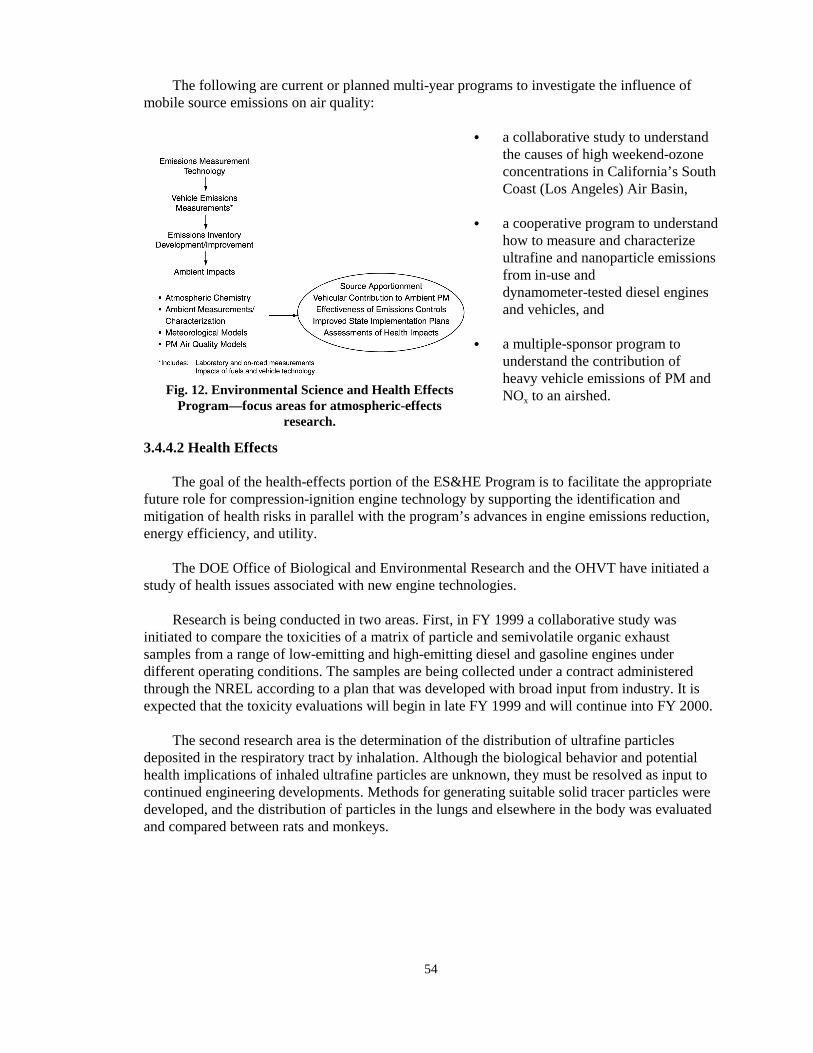
54
Fig. 12. Environmental Science and Health EffectsProgram—focus areas for atmospheric-effects
research.
The following are current or planned multi-year programs to investigate the influence ofmobile source emissions on air quality:
� a collaborative study to understandthe causes of high weekend-ozoneconcentrations in California’s SouthCoast (Los Angeles) Air Basin,
� a cooperative program to understandhow to measure and characterizeultrafine and nanoparticle emissionsfrom in-use anddynamometer-tested diesel enginesand vehicles, and
� a multiple-sponsor program tounderstand the contribution ofheavy vehicle emissions of PM andNOx to an airshed.
3.4.4.2 Health Effects
The goal of the health-effects portion of the ES&HE Program is to facilitate the appropriatefuture role for compression-ignition engine technology by supporting the identification andmitigation of health risks in parallel with the program’s advances in engine emissions reduction,energy efficiency, and utility.
The DOE Office of Biological and Environmental Research and the OHVT have initiated astudy of health issues associated with new engine technologies.
Research is being conducted in two areas. First, in FY 1999 a collaborative study wasinitiated to compare the toxicities of a matrix of particle and semivolatile organic exhaustsamples from a range of low-emitting and high-emitting diesel and gasoline engines underdifferent operating conditions. The samples are being collected under a contract administeredthrough the NREL according to a plan that was developed with broad input from industry. It isexpected that the toxicity evaluations will begin in late FY 1999 and will continue into FY 2000.
The second research area is the determination of the distribution of ultrafine particlesdeposited in the respiratory tract by inhalation. Although the biological behavior and potentialhealth implications of inhaled ultrafine particles are unknown, they must be resolved as input tocontinued engineering developments. Methods for generating suitable solid tracer particles weredeveloped, and the distribution of particles in the lungs and elsewhere in the body was evaluatedand compared between rats and monkeys.

55
The following are current and planned multi-year programs to investigate the influence ofmobile-source emissions on health effects.
� Compare exhaust-emissions toxicity from gasoline and diesel-powered vehicles.
� Provide a linkage between relative toxicity as evaluated in cells and toxicity as measured inmammals.
� Determine the health implications of ultrafine particles by examining the behavior ofultrafine organic particles in different regions of the respiratory tract.
� Compare health effects of gasoline and diesel emissions in animals exposed by inhalation.
3.4.5 Truck Safety
As more energy-efficient trucks are developed, care must be taken to ensure that truck safetyis not compromised. Truck safety encompasses numerous topics, including driver control, crash-energy management, and vehicle stability. Efforts to reduce total vehicle weight will relyprimarily on increased use of lightweight materials and innovative designs. However, theintroduction of alternative materials or designs must not sacrifice the ability of the driver tocontrol the vehicle or the vehicle’s ability to absorb energy during crashes. Trucks and SUVsmade lighter to improve fuel economy must be evaluated for tendencies to roll over or becomeunstable in crosswinds. Since aerodynamic drag currently provides a significant fraction of theforce required to stop a truck, reduction in aerodynamic drag resulting from more streamlined,energy-efficient designs and other drag-reducing technologies described in Sect. 3.4.6 willimpose significantly greater requirements on brake systems. The development of improved brakesystems, therefore, is a safety-related enabling technology for the development of trucks withreduced aerodynamic drag.
This Technology Roadmap covers only the major safety-related issues likely to beinfluenced by advances in energy-efficient technologies. These include
� improvements of brakes and braking systems to compensate for the decreased drag thatresults from improved vehicle aerodynamics or other reductions in running resistance;
� evaluation of crash-energy management to take into account increased use of advancedmaterials and designs that reduce weight;
� evaluation of improved body and frame designs to protect occupants during rollover; and
� evaluation of more energy-absorbing front-end structures, made possible as the developmentof more efficient thermal-management systems reduces the need for space under vehiclehoods.
3.4.5.1 Status of Technology
Brakes. Heavy-vehicle braking systems are typically air brakes with the pressure to operate thebrake mechanisms coming from an engine-driven pumping system. State-of-the-art truck brakesystems in the United States are disk brakes on the front wheels and standard drum brakes on therear of tractors and on trailers and dollies. In Europe, there has been a major switch to disk brakesystems; these systems are expected to attain 50% market penetration in 1999 and 80% by 2002.

56
Advancements in truck brake systems currently being evaluated in the United States includeautomatic slack adjustment, anti-lock braking systems (ABSs), and improved materials ofconstruction, including the friction materials themselves. Under evaluation for application in thelonger term are disk brake systems, traction-control systems (TCSs), and vehicle dynamic control(VDC) systems. Futuristic concepts include “smart” brake systems or self-adaptive systems thatare fully integrated with the total vehicle electronic systems.
Efforts to reduce the weight of vehicles for energy efficiency include the consideration oflighter-weight brake system components; this implies a need to dissipate more energy in lighter-weight vehicles. Aluminum and/or aluminum/alumina or aluminum/SiC composite brake rotorsare beginning to be used in some cars. Whether similar efforts are under way for heavy vehiclesis unknown.
There are many other opportunities for improvements in heavy vehicle brake systems. Arecent ATA document discusses the truckers’ needs for reliability and durability (a brakingsystem that will work the same way repeatedly and last a long time between overhauls).20 Thelong lifetime of some tractors and most trailers has led to an incompatibility problem in whichthe trailer’s braking system is not matched well with that of the tractor because of advancementsmade in one but not the other. This may lead to a mismatch in the application or release ofbraking power of as much as several seconds between the tractor and the trailer. Mistimed orunequal application of either the tractor or trailer brakes leads to loss of vehicle control and“jackknifing” or “trailer swing.”
Reliable and durable systems do not currently exist to assist the trucker in determining thestate of his brake components while on the road. Brake adjustment may vary from wheel to wheelas materials wear differently, and one brake may reach its maximum useful life before another onthe same vehicle, causing an unbalanced distribution of brake power and a potential safetyproblem.
The introduction of hybrid propulsion systems in Class 3–6 trucks will involve the use ofregenerative braking. The design and implementation of electrical generators for regenerativebraking in concert with existing mechanical braking systems provides an opportunity for overallsystem improvement. Heavy vehicles typically have space available in which to locate peripheralor safety equipment. It has been proposed that some of this space could best be used for aregenerative braking system, providing a system to recuperate the power of stopping by charginga battery which could then be used to accelerate the vehicle. Used in combination with the hybridpropulsion systems (discussed in Sect. 3.3.2) these devices could save considerably on theamount of fuel utilized in accelerating heavy hybrid vehicles.
It will be desirable to capture as much of the braking energy as possible, but it is unlikelythat the electrical generators will be sufficiently large to handle the high power requirements.Also, the batteries may not have sufficient energy-storage capacity to store all of the regeneratedenergy. It is reasonable to expect that mechanical braking systems will continue to be standardequipment on vehicles with hybrid propulsion systems.
Materials and Designs for Weight Reduction. Currently, most trucks rely on relatively heavysteel frames and components to provide strength and stiffness necessary to achieve desired load-carrying capability and to provide adequate crash-energy management. Lightweight materials,such as aluminum and polymer composites and designs that address the use of high-strengthsteels are being evaluated in various segments of the ground transportation industry to achieve
57
weight-reduction goals. The ability of these new materials to provide adequate or improvedcrash-energy management is extremely important and is being addressed for passenger vehicles by the OAAT as well as by the automotive industry. Additional efforts will be required to ensurethat these issues are addressed for trucks.
Front-end Structures. The design of Class 7 and 8 tractors is currently controlled, to a largeextent, by the need to incorporate larger engines with the necessary peripherals (e.g.,turbochargers, cooling systems, and air-handling systems). The size of these componentsgenerally precludes the use of advanced aerodynamic designs and does not allow for theconsideration of new, more-efficient, crash-energy management systems; rather, safety in crashsituations is provided by heavy steel construction. However, innovations in thermal managementand air handling may make it possible to significantly downsize many compenents under thehood. The space that is made available would provide room for new crash-energy-managementmaterials and designs to enhance the safety of these vehicles.
3.4.5.2 Technical Targets
For brake systems, the primary technical target is development of a braking system that iseffective at stopping a fully loaded vehicle in as short a distance as possible, while exhibiting theattributes of durability, reliability, and maintainability. The system should also be able toconstantly present the driver with an indication of its state of readiness and repair. Stoppingdistances and stability controls should meet or exceed all existing and planned federalregulations, while remaining able to do so for 100,000 miles without repair or replacement. Areliable and durable, simple-to-read, easily maintained system to indicate readiness and repairstatus should be designed and implemented.
The principal target related to the increased use of alternative lightweight materials isoptimization of the materials and/or designs for fuel efficiency as well as for crash-energymanagement and occupant protection.
3.4.5.3 Barriers
Barriers to the development and implementation of improved truck-braking systems include(1) the current lack of materials for brake components that can either tolerate or dissipate thestress and heat generated during braking without experiencing excessive wear, (2) the currentlack of cost-effective, rugged designs for dissipation or utilization of the braking-generated heat,(3) the cost of improved systems, and (4) the lack of awareness of and experience with currentlyavailable improved systems.
Barriers to the optimized design for crash-energy management include the lack ofunderstanding of energy-absorption mechanisms for new materials and the lack of a designdatabase.
3.4.5.4 Technical Approach
The technical approach to improving truck safety will include the following steps.
� Develop improved frictional materials. This would involve performance of tests on variousprocured friction pairs to include friction and wear measurements as well as thoroughmaterials characterization to determine types, quantities, and microstructures of thefrictional materials. Testing would also involve preparing and testing new experimental

58
frictional materials in an attempt to develop improved materials based on knowledgegenerated by testing the procured materials.
� Evaluate potential regenerative braking systems.
� Develop and implement sensors and actuators for brake safety systems, utilizing sensingtechnologies to measure signals from the brake hydraulic system, and analyze these signalsto detect the development of potential problems. For instance, the signal-analysis systemcould determine the forces applied to each brake and could be used with actuator valves toactively balance these forces and thus control the vehicle’s braking dynamics. Signals frombrake system hydraulics or other sources could also be used to determine the extent of brakewear and thus the need for repair.
� Assess entirely new designs for braking systems, such as electric or hydraulic systems, oreven systems that could act independently of the wheels and tires, such as aerodynamicdevices like the flaps or air deflectors currently used on airplanes.
� Develop predictive-modeling capabilities to aid in enhancing crash-energy managementperformance of new advanced lightweight materials.
� Develop an empirical database on high-strain-rate deformation behavior of new materials.
� Develop and evaluate innovative designs for crash-energy management and for the provisionof occupant safety in rollovers.
3.4.6 Engineering Simulations and Modeling
Computational models continue to play an ever-increasing role in the development of alltransportation vehicles. This trend is largely fueled by the need to further refine vehicle designsfor increased efficiency and performance. It is enabled by the continuing dramatic increases inthe computational power of multiprocessor computers. Computational models that directlysupport the development of efficient heavy vehicles include (1) structural models (static,dynamic, and crash); (2) computational fluid-dynamics (CFD) models (vehicle aerodynamics andfuel handling and mixing); and (3) combustion models (in-cylinder combustion and exhaustaftertreatment). Once validated against controlled experiments, these analytical methods becomevaluable tools to evaluate and optimize the performance of components or processes. Whenlinked together, these simulations can be performed concurrently and/or in series to predict theinteraction of multiple phenomena on system performance. Three areas where computationalmodels can greatly improve heavy vehicle efficiency are (1) materials and structural modeling;(2) fuel injector, combustion, and aftertreatment modeling; and (3) external aerodynamics.
3.4.6.1 Materials and Structural Modeling
Fuel efficiency and lower emission standards have driven the heavy vehicle industry to uselighter-weight structures of steel, aluminum, plastics, and magnesium. These lightweightmaterials and improved designs have also required improved engineering analysis, includingcrashworthiness modeling. The following questions must be convincingly answered during thedevelopment of a successful vehicle design.
� Can efficient processes be engineered to manufacture the components and assemble thevehicle?

59
� Will the as-built performance meet the required acceptance standards?
� Will the as-used performance (in normal and accident conditions) satisfy the necessaryeconomic, environmental, and safety standards that are imposed?
Current vehicle development cycles require that many real prototypes be built and tested infull-scale crash experiments. Although final acceptance of vehicle designs should continue to beconfirmed in actual tests, the development of larger, more powerful computers provides theopportunity to use modeling and simulation for optimizing design solutions, thus reducing avehicle’s development cost and time to market.
3.4.6.2 Fuel-Injector Modeling
The historical improvement in power and efficiency of diesel engines is due, to some extent,to advances in efficiency and precise fuel delivery through better fuel injectors. Adequatein-cylinder mixing between fuel and air is strongly dependent on the characteristics of the fuelinjector, in addition to other conditions, such as chamber pressure and geometry. This isespecially true for DI engines, in which the fuel is directly injected into the cylinder without anyprior contact with the air.
Because fuel-spray characteristics such as velocity, spray angle, and droplet size are criticalfactors in fuel-air mixing, it is important to understand the relationship between thesecharacteristics and injector design. Traditionally, injector design has been based on extensiveempirical correlations between experimentally measured spray characteristics and specific designparameters. However, because the dimensions of injector flow passages are small (0.1 mm orsmaller) and their geometries are complex, it is almost impossible to obtain accurate,nonintrusive experimental measurements of the flow inside injectors. Thus, computational fluid-dynamics modeling of the flow inside and at the exit of injectors could provide important newinformation about how design parameters actually relate to spray characteristics.
There are still wide gaps in the understanding of the physical processes inside the injectorand how they relate to the subsequent formation of liquid sheets and drops beyond the injectorexit. One prominent theory is that atomization is caused by aerodynamic interaction of the liquidjet with the gas into which it is injected. Another theory suggests that atomization is caused bythe conversion of turbulent energy within the liquid sheet that is initiated within the injector.High-resolution computational fluid dynamics models of a fuel injector could help resolve thesetheories and could provide both fundamental and specific design information for the nextgeneration of high-efficiency, low-emission, heavy-duty diesel engines.
The flow within the fuel injector is at the extreme limits of the continuum regime andborders on being a nonequilibrium molecular-dynamics regime. In the open literature, there is novalidated model to fully capture the physics of the flow inside the injector. Molecular dynamicsor lattice Boltzmann calculations have been used with some success in the past for microelectro-mechanical systems (MEMS) and ink injectors of printers. Continuum approaches suchas volume-of-fluid, boundary integral method, and the level-set method, and have shown promisein modeling the complex surface interactions in droplet breakup and coalescence. An extensivesystematic testing and validation of this approach to injector modeling is needed to ascertain itslimits and best methodology to be followed. Because of the high level of detail required toadequately describe the fuel-injector phenomena, it is likely that Teraflop-scale, high-

60
performance computing will be a necessity. Such computing capabilities are not available inindustry or at universities but will be available at national laboratories.
Droplet vaporization downstream of the injector can be modeled by solution of the sprayequation by means of a Monte Carlo particle method. This mixed Eulerian-Lagrangian approachmodels the dispersed phase and has the ability to accurately model the dilute (low-liquid-volume-fraction) spray regime. The integration and coupling of this continuum process to the flow withinthe fuel injector needs to be addressed and studied. The result will be a valuable design tool tomodel the next generation of fuel-efficient, low-emission engines. The understanding obtainedwill make it feasible to generate new sub-models that plug into existing codes (e.g., KIVA andCHAD) to model the spray formation processes more accurately.
3.4.6.3 Combustion Models
In-Cylinder Combustion Modeling. Beyond the injector, diesel-combustion performance isdetermined to a large extent by the efficiency with which the liquid fuel droplets evaporate andmix with the air. Thus, it is also important to have computational models that simulate the impactof droplet characteristics (such as velocity and size distributions) and air flow features (such asswirl and tumble). At a minimum, this type of simulation requires consideration of thethree-dimensional continuum turbulence associated with both flows. Further, the heat releasedduring combustion can modify the turbulence in the flow, resulting in a fully coupled evolutionof the fluid-flow and chemical processes. All these processes are highly unsteady and occur inmost real systems in an environment of major transients (e.g., acceleration) imposed by thedriver. Current understanding of this type of flow field is limited and comes primarily fromlaser-based optical measurements obtained through the use of optically accessible single-cylinderengines and engine simulators. Future advancement in engine design and increases in efficiency(i.e., reduced fuel consumption and pollutant emission) will require significant furtherimprovements in our understanding of how the flow and combustion processes couple together inthis transient environment.
Numerical simulation of key aspects of in-cylinder combustion coupled with advancedexperimental approaches will begin to play an integral role in developing this enhancedunderstanding of flow and combustion processes. For example, KIVA and CHAD are existingstate-of-the-art computer codes that have already been successfully used by industry and DOE tostudy certain aspects of diesel combustion. Both of these codes are widely known for their abilityto simultaneously address both the computational fluid dynamics and at least low-orderdescriptions of the combustion chemistry. However, it is also clear that there are many importantphenomena that cannot currently be simulated by these codes. For example, a detaileddescription of how NOx and PM generation are related to the precise combustion sequence hasyet to be achieved, perhaps because the chemical kinetics submodels used by these codes is fartoo simplified; also the codes cannot address the coupling between engine cycles that influencesoverall emissions and performance. With the availability of massively parallel systems and therecent development of more detailed reaction kinetics, these limitations can be significantlyreduced.
It is also likely that the turbulence models currently used in codes like KIVA and CHADwill not be able to address some issues of importance to the OHVT. Specifically, since fuel-airmixing and combustion produce large density variations and can vary from cycle to cycle,conventional ensemble-averaged turbulence models used in KIVA and CHAD cannot giveimportant field information. More advanced large-eddy-simulation (LES) and variable-densityturbulence models are just beginning to be implemented and tested in CHAD. The modeling talk

61
will require full implementation and extensive verification and validation of these advancedmodels. In LES, scales larger than the grid are computed using a time- and space-accuratescheme, while the unresolved smaller scales are modeled semi-empirically. A modeling processknown as “bootstrapping” can be used to define the turbulent scaling relationships in thesesub-grid regions, thereby eliminating the need for calibrating various ad hoc modeling constantsand improving the robustness of the modeling procedures.
Aftertreatment Device Modeling. Often, the simultaneous goals of high fuel efficiency and lowemissions are strongly at odds. This is especially true for diesel combustion, which is carried outunder extremely lean (oxygen-rich) conditions that do not favor the subsequent reduction of NOx
in the catalytic converter. In fact, current catalytic converters are, in fact, incapable of reducingdiesel exhaust NOx levels to the proposed new federal standards, and there is no clear route tohow these standards can be met. Clearly, a new level of converter technology will be needed.
Up to the present, development of new catalytic converter technology has depended almosttotally on empirical, incremental developments. Catalysts and converter designs have beeninitially selected on the basis of educated guesses and long-term testing to scale up from thelaboratory to device scale. However, it is expected that models of the dominant physical andchemical processes involved could greatly speed the development of new generations of catalyticconverter technology. It may be possible to reach the stage of the so-called “designer catalysts,”in which totally new catalyst formulations are proposed on the basis of a detailed model relatingcatalyst composition and morphology to on-the-road performance. Although the “designercatalyst” idea has much appeal, it is likely that other developments will initially have morenear-term implementation.
First, there is a strong need to accurately model the flow, mass transport, and heat transportin the exhaust gases flowing through the converter and the coupling between these macroscopicflow effects and the chemical processes occurring on the catalyst surface. This connectionbetween the macroscopic flow field and chemistry is critical because either of these generalregions can dominate the overall converter performance, depending on operating conditions. Inmany cases, the rate-limiting step can switch from one region to another as transients areimposed by the engine. The effect of transients is likely to be particularly important in diesels forcertain operational periods such as cold start and rapid acceleration, which are key parts of theFTP for emissions performance. Transients are also a major factor in the functioning of so-calledNOx traps, where the nitrogen oxides are adsorbed onto special “storage” sites for extendedperiods and then are released and reduced by the addition of hydrocarbon pulses to the converter.
Secondly, there is a major need to develop better models for the surface chemistry andappropriate kinetics models that will accurately reflect the effects of individual exhaust-gasspecies and local variations in temperature. The surface kinetics currently available for most ofthe important reactions are poorly understood and incomplete. The kinetics that are typicallyavailable are derived from experimental global conversion measurements at steady-flowconditions where detailed surface temperature and concentration profiles are unknown. Suchinformation cannot be used to make accurate predictions for flow and boundary conditions thatare significantly different from the experiments used to derive it, and each new catalyst materialmust be empirically evaluated before simulations can be run. Because of the considerablecomputational burden imposed by considering a large number of elementary reaction steps, thereis a strong incentive to identify the major reaction pathways that can have a significant impact onglobal conversion.

62
The above two modeling components could be combined in both fully detailed andlow-order forms. The former term refers specifically to simulations in which the macroscopicflow effects and surface kinetics are considered simultaneously in high detail. Although suchsimulations should offer the most accurate predictions about the impact of design changes orchanges to the catalyst properties, it will require Teraflop levels of computational effort similarto that described for detailed modeling of the in-cylinder combustion. Low-order models offeranother approach for situations where computational speed (as opposed to detail) is essential(such as for real-time diagnostics and control). In this second case, it would be advantageous todevelop simplified versions of the detailed models that can still produce the correct overallsystem dynamic response. An example application would be the evaluation of how thecombination of certain engines and catalyst aftertreatment systems collectively respond to certaintypes of driving transients. Such information could be extremely valuable for assessing theeffectiveness of various types of on-board emissions sensors.
A third major modeling need for diesel emissions control is to simulate the mechanisms forcatalyst poisoning and particle coarsening. Sulfur poisoning is a major issue because of thepotential impact it could have on fuel-processing requirements. Specifically, if alternativemethods are not found for reducing sulfur’s rapid inhibition of lean NOx catalysts, diesel fuelswill have to be processed to extremely low sulfur levels. A detailed model for the physical andchemical processes involved in sulfur poisoning could potentially lead to improvements incatalyst design and/or operation that would significantly increase their sulfur tolerance andwould lessen the need for expensive fuel processing.
Catalyst particle coarsening is one of the major causes of catalyst degradation not caused bypoisoning. It specifically involves the physical migration and agglomeration of individualcatalyst particles in the washcoat so that the effective catalyst surface area is much reduced. Asyet, no one has been able to explain the basic physical mechanisms involved or to predict howcoarsening relates to the initial washcoat morphology or the time-temperature exposure history.Like sulfur poisoning, the impact of coarsening is so large that the development of options forretarding or eliminating it would be considerable.
3.4.6.4 External Aerodynamics
One of the barriers to achieving a 10-mpg truck is vehicle drag (see Sect. 3.1.3). The targetis to reduce the Cd from 0.55 to 0.47, a reduction of 15%. New approaches for the numericalsimulation and analysis of aerodynamic flow will play an important role in the R&D to reduceaerodynamic drag. 21
3.4.6.5 Drag Reduction
CFD calculations of the truck configuration will provide guidance on designs that offer theleast drag. These designs are closely coupled to other requirements such as underhood thermallimitations and the geometric constraints imposed by the functional requirements, of thetractor-trailer combination. Manufacturing costs and other parameters also have to be consideredin this optimization. Experimental verification and validation of new CFD methods are animportant part of this task.21
3.9.6.6 Underhood Thermal Management
Aerodynamic designs offer new challenges in designing the underhood systems andcomponents of trucks. Optimal location and shapes of components (e.g., engine, fans, radiators,

63
heat exchangers, intake manifolds) have to be determined. Advanced high-efficiency trucksrequire optimization of the thermal performance of the power system and a well-characterizedunderhood thermal environment to ensure that electronic control systems and other temperature-sensitive components operate properly. This complicated systems analysis requires theintegration of high-fidelity models of thermal-hydraulic processes that stretch the state-of-the-artin CFD and high-performance computing. The computational model should integrate thermalmodels for convective, conductive, and radiative heat transport as well as integrate models forcritical heat management system components, including cooling fans and radiators.


65
4. PROGRAM SUMMARY
The implementation of this OHVT Technology Roadmap is described in the MultiyearProgram Plan of the Office of Heavy Vehicle Technologies and Heavy Vehicle IndustryPartners22 and in the multiyear program plans listed in Appendix B. The reader should consultthe more detailed multiyear program plans for complete information.
4.1 PROGRAM GOALS
� Develop by 2004 the enabling technologies for a Class 7 & 8 truck with a fuel efficiency of10 mpg (at 65 mph) that will meet prevailing emission standards.
� For Class 3–6 trucks operating on an urban driving cycle, develop by 2004 commerciallyviable vehicles that achieve at least double the fuel economy of comparable current vehicles(1999), and as a research goal, reduce criteria pollutants to 30% below EPA standards.
� Develop by 2004 the diesel-engine enabling technologies to support large-scale industrydieselization of Class 1 & 2 trucks, achieve a 35% improvement in fuel efficiency overcomparable gasoline-fueled trucks, and meet applicable emissions standards.
4.2 PROGRAM APPROACH
� Develop a partnership with the domestic transportation industry, energy-supply industry,other federal agencies, and R&D organizations to develop high-efficiency-enginetechnologies and alternative fuel-utilization technologies for trucks and to promote theiracceptance.
� Continue development of key enabling technologies:—Emission control (including exhaust aftertreatment)—Combustion technology—Materials—Environmental science and health effects—Truck safety—Engineering simulations and modeling

66
Fig. 13. Key activities and schedule of OHVT.
Among these enabling technologies, combustion and emissions control are beingcoordinated through a diesel cross-cut team that has linked diesel R&D in the OHVT and thePartnership for a New Generation of Vehicles (PNGV).
4.3 SCHEDULE AND MILESTONES
The OHVT program key activities and milestones are shown in Fig. 13.

67
5. REFERENCES
1. Office of Transportation Technologies Strategic Plan, August 8, 1996, p. 1. 2. OHVT Technology Roadmap, Office of Heavy Vehicle Technologies, Office of
Transportation Technology, DOE/OSTI-11690, October 1997.3. Stacy C. Davis, Transportation Energy Databook, Edition 17, ORNL-6919, Center for
Transportation Analysis, Oak Ridge National Laboratory, August 1997.4. Annual Energy Outlook, 1999. Energy Information Administration, U.S. Department of
Energy, DOE/EIA-0383 (98), July 1998.5. AAMA Facts and Figures, 1998. American Automobile Manufacturers Association,
Washington, D.C., 1998.6. J. B. Heywood, Internal Combustion Engine Fundamentals, McGraw-Hill Publishing Co.,
1988, p. 883.7. R. R. Covey, Preliminary Heavy-Duty Truck Energy Balance, Aerospace Corporation,
August 1982.8. R. L. Graves, D. L. Greene, and E. W. Gregory II, Application of the Adiabatic Diesel to
Heavy Trucks—A Technology Assessment, ORNL/TM-9554, March 1986.9. H. M. Sachs et al., Heavy Truck Fuel Economy: A Review of the Technologies and the
Potential for Improvement, American Council for an Energy Efficient Economy,Washington, D.C., January 1992.
10. G. F. Roberts and D. L. Greene, Trends in Heavy Truck Energy Use and Efficiency,ORNL/TM-8842, Oak Ridge National Laboratory, October 1983.
11. R. L. Wiley and L. Levine, Aerodynamic Design Effects on Passenger Car and Truck FuelEconomy, Aerospace Corporation, ATR-83 (3869)-IND, December 1982.
12. B. Randall, An Integrated Approach to Truck Fuel Saving, Automotive Engineer,January–March 1991.
13. Federal Register, Vol. 61, 33421, June 26, 1996.14. R. H Hammerle, et al., “Emissions from Current Diesel Vehicles,” Society of Automotive
Engineers Paper No. 942043, 1994.15. K. J. Springer, “Diesel Lube Oils—4th Dimension of Diesel Particulate Control,” American
Society of Mechanical Engineers, ICE-Vol. 4, 45, 1988.16. Multiyear Program Plan Advanced Petroleum-Based (APB) Fuels R&D for Compression-
Ignition, Direct-Injection Engines and Emissions Control Systems, Office of AdvancedAutomotive Technologies, Office of Heavy Vehicle Technologies, Draft, July 1999.
17. R. H. Miller, “Supercharging and Internal Cooling Cycle for High Output,” Trans. ASME69, 1947.
18. California Code of Regulations, Title 13, Sections 1960.1 (k) and 1961 (d).19. Federal Register, Volume 64, No. 92, May 13, 1999.

68
20. RESEARCH AGENDA, a written document with no publication information, obtainedthrough Dr. Sidney Diamond, via Vic Suski of ATA, April 1996.
21. Rose McCallen et al., “Progress in Reducing Aerodynamic Drag for Higher Efficiency ofHeavy Duty Trucks (Class 7 & 8),” presented at 1999 Society of Automotive EngineersGovernment/Industry Meeting, Washington, D.C., April 26–28, 1999.
22. Multiyear Program Plan of the Office of Heavy Vehicle Technologies and Heavy VehicleIndustry Partners, DOE-ORO/2071, August 1998.
APPENDIX A. OHVT WORKSHOPS AND MEETINGSTO SOLICIT CUSTOMER INPUT


A-3
APPENDIX A. OHVT WORKSHOPS AND MEETINGSTO SOLICIT CUSTOMER INPUT
DOE/SAE Workshop on Energy Efficient Heavy Vehicle Technologies for Reducing Fuel Costs:Leveraging DOE’s R&D Capabilities, Romulus, Michigan, April 17–18, 1996.
DOE/Office of Heavy Vehicle Technologies Customer Focus Workshop, Golden, Colorado, May14–15, 1996.
SAE Truck and Bus Council Meeting, Miami, Florida, June 24–25, 1996.
DOE/OHVT Workshop on Applications of Carbon Products for Efficient Operation of HeavyTrucks, Buses, and Other Commercial Vehicles, Chicago, Illinois, September 4–5, 1996.
1996 SAE International Truck and Bus Meeting and Exposition, Detroit, Michigan, October14–16, 1996.
DOE Automotive Technology Development Customers’ Coordination Meeting, Dearborn,Michigan, October 28–November 1, 1996.
Workshop on Alternative Fuels for Heavy Vehicles, Chicago, Illinois, November 1996.
Workshop on Improving Heavy Vehicle Aerodynamics, Phoenix, Arizona, January 1997.
1997 Diesel Engine Emissions Reduction Workshop, La Jolla, California, July 28-31, 1997
DOE-OTT Automotive Technology Development Customers’ Coordination Meeting, Dearborn,Michigan, October 1997.
DOE-OHVT/Energy Frontiers International Fuels and Engines Meeting, in San Antonio, Texas,January 14, 1998. (Attended by representatives from the oil industry and enginemanufacturers.)
Workshop on Performance and Emissions of New Diesel Cycle Fuels for Heavy Vehicles, SanAntonio, Texas, January 15, 1998.
Workshop to Review Multi-Year Program Plan on Heavy Vehicle Aerodynamic Drag, Livermore,California, February 20, 1998.
DOE/Engine Manufacturers Association Meeting on New Motor Fuel Options for DieselEngines, Washington, D.C., March 16, 1998.
1998 Diesel Engine Emission Reduction (DEER) Workshop, Castine, Maine, July 6–9, 1998.
DOE-OHVT/Energy Frontiers International “Fuels, Lubricants, Engines, and Emissions”Meeting,, San Antonio, Texas, January 18–20, 1999. (Attended by representatives from theoil and lubricants industry, engine manufacturers, emissions-control manufacturers, andhealth-effects community representatives.)

A-4
DOE-OHVT Workshop on Emissions Control Strategies for Internal Combustion Engines,Tucson, Arizona, January 21, 1999.
Workshop on Research Needs for Reducing Friction and Wear in Transportation, Argonne,Illinois, March 22–23, 1999.
1999 SAE Government/Industry Meeting, Washington, D.C., April 26–28, 1999.
1999 Diesel Engine Emission Reduction (DEER) Workshop, Castine, Maine, July 5–9,1999.
HTML User Forum, Knoxville, Tennessee, August 16–17, 1999.
DOE/ORNL Workshop on “Opportunities for Heavy Vehicle Energy Efficiency Gains ThroughRunning Resistance and Braking Systems R&D, Knoxville, Tennessee, August 18–19, 1999.
Heavy Vehicle Propulsion Materials Workshop, Knoxville, Tennessee, August 19–20, 1999.

APPENDIX B. MULTIYEAR PROGRAM PLANS


B-3
APPENDIX B. MULTIYEAR PROGRAM PLANS
Multiyear Program Plan of the Office of Heavy Vehicle Technologies and Heavy VehicleIndustry Partners, DOE-ORO/2071, August 1998.
Heavy Truck Engine R&D, Program Plan FY 2000-2004, Office of Heavy VehicleTechnologies, Office of Transportation Technologies, Energy Efficiency and RenewableEnergy, U.S. Department of Energy, November 1999 (Draft).
Light Truck Engine R&D, Program Plan FY 1999-2003, Office of Heavy VehicleTechnologies, Office of Transportation Technologies, Energy Efficiency and RenewableEnergy, U.S. Department of Energy, May 1999 (Draft).
Heavy Vehicle Hybrid Propulsion Systems R&D, Program Plan FY 1999-2003, Office ofHeavy Vehicle Technologies, Office of Transportation Technologies, Energy Efficiency andRenewable Energy, U.S. Department of Energy, March 1999 (Draft).
Diesel Engine Combustion Research, Program Plan FY 1998-2002, Office of Heavy VehicleTechnologies, Office of Transportation Technologies, Energy Efficiency and RenewableEnergy, U.S. Department of Energy, June 1998 (Draft).
Energy Efficiency in Heavy Vehicle Tires, Drivetrains, and Braking Systems: Draft Multi-Year Program Plan for Running Resistance, Peter Blau, December 22, 1999 (Draft).
The Multi-Year Program Plan for the High Temperature Materials Laboratory, ORNL, ArvidPasto, in draft form 1/3/2000
Heavy Vehicle Propulsion Materials Draft Multi-Year Program Plan, Revision 4, Office ofHeavy Vehicle Technologies, Office of Transportation, U.S. Department of Energy,September 28, 1999
Multi-Program Plan-Reducing Friction and Wear in Heavy Vehicles, September 1999 (Draft)
Multi-Year Program Plan Advanced Petroleum-Based (APB) Fuels R&D for Compression-Ignition, Direct-Injection Engines and Emissions Control Systems, Office of AdvancedAutomotive Technologies, Office of Heavy Vehicle Technologies, Draft, July 1999.
A Multi-Year Program Plan for the Aerodynamic Design of Heavy Vehicles, LawrenceLivermore National Laboratory, UCRL-PROP-127753 Dr Rev 1, February 1998
Comprehensive Program Plan for Natural Gas Vehicle Research, Office of Heavy VehicleTechnologies, May 1997