OGUE - besafedirect.com · 4 A Greener Solution to Emergency Lighting The FIRElux system is based...
28
The UK s First Low Voltage, intelligent LED EMERGENCY LIGHTING SYSTEM world class leaders in fire detection ABC a from Member of Low Cost High Quality Low Carbon Emissions Innovative Technology UK Manufactured Low Maintenance PRODUCT CATALOGUE ‘ contains complete Product Specifications
Transcript of OGUE - besafedirect.com · 4 A Greener Solution to Emergency Lighting The FIRElux system is based...

The UK s First LowVoltage, intelligentLED EMERGENCYLIGHTINGSYSTEM
world class leaders in fire detectionABCafrom
Member of
Low CostHigh Quality
Low Carbon EmissionsInnovative Technology
UK ManufacturedLow Maintenance
PRODUCT CATALOGUE
‘
contains complete Product Specifications

Contents
2
Introduction 3
A Greener Solution to Emergency Lighting 4
The Benefits of FIRElux 5
Escape Route Corridors 6
Energy Consumption and CO2 Emissions 7
System Structure 8
FIRElux Products 10-18
FIRElux Accessories 19-22
FIRElux Software 23
FIRElux Photometric Data 24-25
Design Guide 26
Index 27
Cost Effective and EnvironmentallyFriendly Emergency Lighting
Hochiki Europe, world leaders in fire detection manufacturing introduces a brand new concept to theUK market - an innovative new Emergency Lighting system, FIRElux.
FIRElux is a unique, highly cost effective and environmentally friendly emergency lighting systembased on LED technology and is the UK’s first to be fully intelligent.
FIRElux is based around an addressable, emergency lighting control panel with battery back-up andfeatures addressable, self contained luminaires and signage connected via traditional low-voltage(24V) cabling.
With lighting units fitting directly onto the standard Hochiki Europe sensor base (YBN-R/3) FIREluxoffers the installer a brand new and easy solution to the installation of emergency lighting andsignage.
3
Low VoltageLess than 5% energy consumption comparedto traditional lighting*1
IntelligentUnique intelligent addressable technologyallows control and testing of individualluminaires
LED TechnologyLow carbon emissions – less than 5% CO2
compared to traditional lighting*2
Manufactured inthe UKBuilt and tested by Hochiki Europe in UK
Low MaintenanceLess than 1% lamp changes when compared totraditional lighting*3
Simple InstallationLuminaires fit onto the standard HochikiEurope sensor mounting base (YBN-R/3)
*1 Figure based on tests of 100 luminaires over 10 years*2 Figure based on comparison of traditional fluorescent tubing with FIRElux installation of 100 luminaires*3 Figure based on lamp changes over a ten year period for a system of 100 luminaires
Graphics SoftwareAllows instant overview of complete systemand assists in maintenance tasks

4
A Greener Solution to EmergencyLighting
The FIRElux system is based on LED (Light Emitting Diode) solutions that consider the useful life of theentire emergency light system, from its installation to the recycling of the equipment at the end of thelife-cycle.
The FIRElux emergency light system uses fully recyclable materials that do not place an unnecessaryburden on the environment. Due to their unique low-voltage solution, cabling costs are reduced by60% during installation when compared to old central battery-based systems.
Due to its luminary-specific backup power source, the FIRElux lighting system can use regular firealarm cabling, instead of heavy Fire Resistant cables. Due to its unique design software, installationcosts, including configuration processes, are significantly lower than that of traditional systems.
The environmentally friendly values in the FIRElux emergency lighting system are specifically evidentin the energy costs and CO2 emissions, which are associated with using and maintaining the system.
The graph (right) compares theenergy consumption and CO2
emissions of emergency light systemsusing traditional mains-poweredfluorescent technology, a mains-powered LED equivalent and the low-voltage FIRElux system, on an annualbasis in a 100-luminaries installation.
The FIRElux emergency light systemhas also been designed, bearingoperational safety and user-friendliness in mind. An internalcontrol system has been includedwith the system. It constantlycontrols the condition of the lights’LEDs and batteries. If necessary, thesystem will provide specificinformation on the status, eitherlocally on a keypad or by transferringit to the control centre of the serviceprovider using an IP or GSM network.
Using graphical software, the statusinformation can be linked with thefloor plans showing the alarmlocations.

5
The Benefits of FIRElux
u Environmentally friendly in energy costs and C02 emissions
u A cost-efficient system to implement and maintain
u No complicated measurements required for the installation
u Exit and emergency lights, which use the same channel
u Easy installation
u No expensive cabling
u Bus length 500/1,000M
u Up to 127 luminaries, using one bus
u Operational reliability, using luminary-specific backup power sources
u Easy to service and maintain
u The system includes an automatic testing feature
u An existing system can be easily updated to use addresses without requiring additional cabling
Operational Reliability
According to a new way of thinking, the FIRElux luminaries are connected using standard 2-core
1.5mm2 cable, which reduces installation costs traditionally associated with fire alarm systems. All
FIRElux luminaries are equipped with battery backups. The lights will function in every situation, even
in the event that the control panel is damaged or inoperable or the bus cable is severed.
The FIRElux emergency light system fulfils all security light standards, such as EN 50172,
for example. The functions of the system are new and unique in the world.
A Pioneer in Exit Lighting
FIRElux is an intelligent emergency light system. The light cabling is completed using a so-called tree
structure, which means that several branches can be isolated from the main cable for different floors
and locations of the facility. Due to its programmability, exit and route lights can be freely installed to
the bus without having to group to exit or route light. The control panel constantly monitors the
condition of the luminaries and regularly performs the periodical testing required by legislation.

6
Escape Route Corridors
The installation gap for LED-based route lights can be 10 metres, at a height of 3 metres. The lightshave ten aligned LEDs, which illuminate the floor in a rectangular pattern. When compared to thetraditional spot light, the FIRElux-DL illuminates a uniform path in both width and length. Thebrightness of the route light is 1 to 6.5 lux, depending on the ceiling height and install distance. Thelights are extremely suitable for corridors and designated escape routes.
Quick and Easy Installation
Installation-friendly emergency lights are literally installed at the turn of a hand. The cabling andbases of luminaries can be installed in advance and the lights are attached to the bases during thefinal phases of construction. This way, the unit is not required to be protected from construction-related dust, dirt, or damage.
1s 2s 3 seconds

7
Energy Consumption and CO2
Emissions
A FIRElux exit luminary consumes less than 0.5W, including the power loss. A similar 8W fluorescentlight exit luminary will consume approximately 12W. When compared to 230V LED lights, FIREluxproducts save more than 50 % of energy. The lower energy consumption directly correlateswith lower CO2 emissions. For example, replacing 100 230V fluorescent exit luminaries with FIREluxLED-based exit lights, CO2 emissions would be reduced by 2,100 KG annually.
This would also result in over £370 energy cost savings annually for the end user.
Automatic Monitoring
FIRElux luminaries use LEDs in order to generate the necessary illumination whilst using as low acurrent as possible. Even at its highest, the LED current usage is only 80% of the recommendedcurrents of LED manufacturers. This way, the light power consumption has been kept to a minimumand the useful life has been extended.
The use of several LEDs in the luminaries is also a safety factor, as even with the malfunction of oneLED, the light will still illuminate. FIRElux luminaries have a brilliant brightness control and monitoringsystem, which will increase the brightness of the other LEDs, when a malfunction of one or more LEDsis detected.

8
System Structure
FIRElux brings new technology with new opportunities and solutions for emergency exit lighting.
The core of the FIRElux emergency lighting system is the addressable FIRElux-2 emergency light control panel.Altogether 254 exit signs and/or route lights can be connected to the two addressable spurs. Both exit signsand route lights utilise LED (Light Emitting Diode) technology, which guarantees around 10 years lifetime (forexit sign usage). The unique ‘Flex-it’ hinge system in the exit signs allows both wall and ceiling mountingutilising the standard Hochiki sensor mounting base, YBN-R/3.
The equipment is controlled by the discreet FIRElux-KP keypad which features an LCD graphic display. Thekeypad display can show the address and location text of a device activated or in fault.
MaintenanceThe EN 50172 security system standard has placedparticular attention on the operational condition ofemergency light systems. The system should beregularly tested once a month, as the minimum. Thecontrol panel of the FIRElux emergency light systemcontinuously monitors and tests the functionality ofthe system automatically. Information on the testprocedure is stored in the memory of the panel and themalfunction/ alarm information is displayed on thescreen of the keypad.
CablingCabling of the FIRElux system is easily and quicklyachieved using traditional cable. This is because therechargeable battery backup is contained within eachand every luminaire on the system. The system can bewired as a spur. Exit lights can be connected in parallelwithout grouping. FIRElux allows the connection of thecabling to luminaire bases before installing the lightunits. Most units are fitted to the base with a simpleand fast ‘twist-fit’ method, reducing installation time.
Control CentreAny fault information from the FIRElux emergency lightsystem can be linked to HHL graphic software floor-plans as alarm points, as part of the security system ofthe entire facility. Using addition software, the FIREluxemergency light system can be maintained from thecontrol room.
9
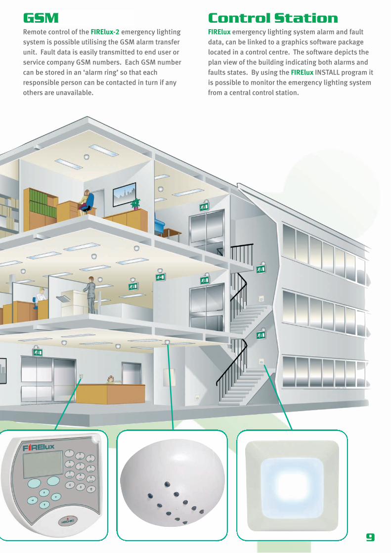
GSMRemote control of the FIRElux-2 emergency lightingsystem is possible utilising the GSM alarm transferunit. Fault data is easily transmitted to end user orservice company GSM numbers. Each GSM numbercan be stored in an ‘alarm ring’ so that eachresponsible person can be contacted in turn if anyothers are unavailable.
Control StationFIRElux emergency lighting system alarm and faultdata, can be linked to a graphics software packagelocated in a control centre. The software depicts theplan view of the building indicating both alarms andfaults states. By using the FIRElux INSTALL program itis possible to monitor the emergency lighting systemfrom a central control station.

10
The FIRElux-2 emergency light control panel features two bus channels, each bus canaccommodate 127 exit signs and/or route lights. The FIRElux-2 supplies theoperational voltage to the light units during normal conditions, whilst alsocompleting the continuous testing and monitoring of the equipment on the system.All monitored event information is saved in the memory of the control panel, and thiscan be accessed by a connected FIRElux-KP key pad (see page 11).
Number of lights/signs supported 254 Connection voltage 35 Va.c. (222 VA)Nominal voltage 12 Vd.c.Internal batteries capacity 7.2 AhI/O outputs 2 relay outputsModem connection RS-232User panel connection RS-485/9600 baudEvent memory 500 eventsDimensions (mm) 295W x 475H x 100D
FIRElux-2 Addressable Control Panel
11
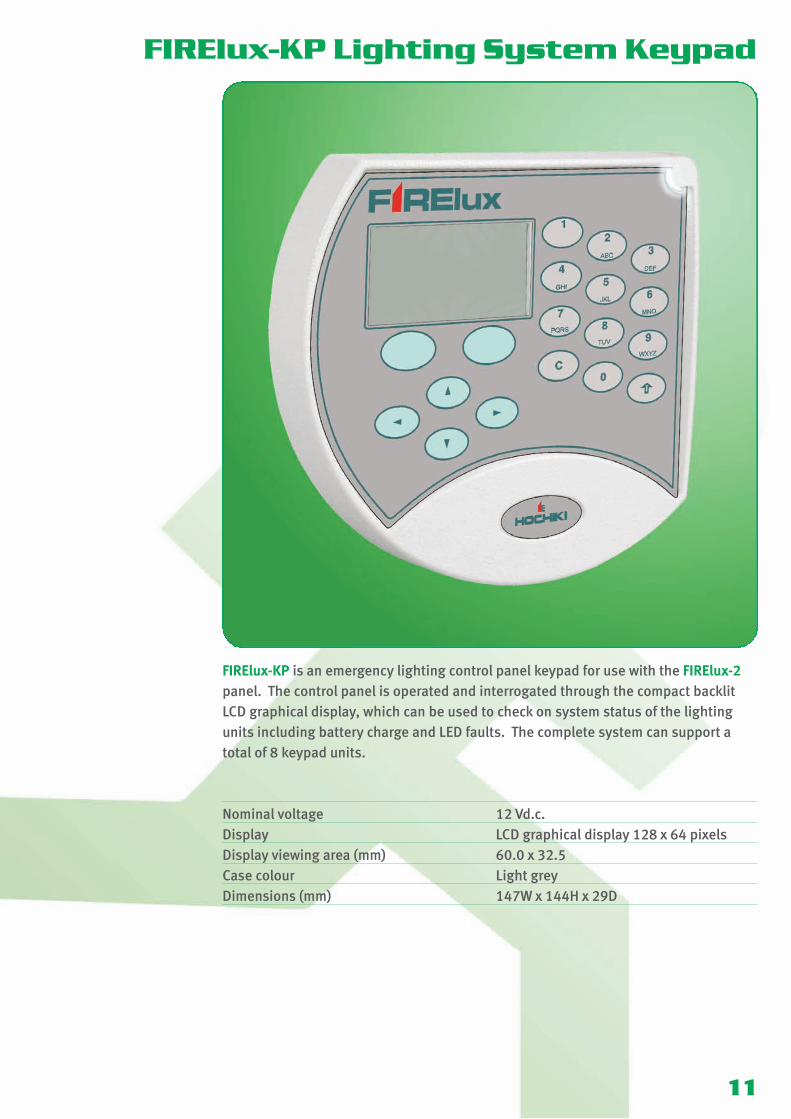
FIRElux-KP is an emergency lighting control panel keypad for use with the FIRElux-2panel. The control panel is operated and interrogated through the compact backlitLCD graphical display, which can be used to check on system status of the lightingunits including battery charge and LED faults. The complete system can support atotal of 8 keypad units.
Nominal voltage 12 Vd.c.Display LCD graphical display 128 x 64 pixelsDisplay viewing area (mm) 60.0 x 32.5Case colour Light greyDimensions (mm) 147W x 144H x 29D
FIRElux-KP Lighting System Keypad

12
A LED-based, addressable 40m viewable exit light with a flexible ‘flex it’ hingesolution. The exit light’s hinge cup contains the address unit and back-up battery andallows the unit to attach to the standard Hochiki YBN-R/3 sensor mounting base.
Cup colour IvoryMaterial Fire resistant PC + ABS plastic (FR3010)
Plexiglass-8N (sign)Fire class UL94 V-OViewing distance 40mModels available FIRElux-40L (arrow to left)
FIRElux-40R (arrow to right)FIRElux-40D (arrow down)
Operation time 1 hour/3 hourDimensions of sign (mm) 300W x 226H x 23D Distance from wall (in wall installation) 75 (inc 8mm for YBN-R/3 base)Drop from ceiling (in ceiling installation) 295 (inc 8mm for YBN-R/3 base)
FIRElux-40 Addressable Exit Sign
FIRElux-40D

13
A LED-based, addressable 20m viewable exit light with a flexible ‘flex it’ hingesolution. The exit light’s hinge cup contains the address unit and back-up battery andallows the unit to attach to the standard Hochiki YBN-R/3 sensor mounting base.
Cup colour IvoryMaterial Fire resistant PC + ABS plastic (FR3010)
Plexiglass-8N (sign)Fire class UL94 V-OViewing distance 20mModels available FIRElux-20L (arrow to left)
FIRElux-20R (arrow to right)FIRElux-20D (arrow down)
Operation time 1 hour/3 hourDimensions of sign (mm) 200W x 46H x 23D Distance from wall (in wall installation) 75 (inc 8mm for YBN-R/3 base)Drop from ceiling (in ceiling installation) 217 (inc 8mm for YBN-R/3 base)
FIRElux-20 Addressable Exit Sign
FIRElux-20D

FIRElux-DL is a LED-based, addressable route light/downlighter featuring ten LEDs.The installation interval of the lights is 7.7m, at an installation height of 3.5m. Theunit’s cup fixture contains the address unit and the back-up battery. The unit hasbeen designed to easily fit onto Hochiki’s standard sensor base, the YBN-R/3 and ismanufactured to the same colour to seamlessly integrate with the Hochiki range offire detection devices.
Case colour IvoryCase material Fire resistant PC + ABS plastic (FR3010)Fire class UL94 V-OOperation time 1 h/3hDimensions (mm) 99.7Ø x 50H (inc 8mm for YBN-R/3 base)
FIRElux-DL Addressable Downlighter
14
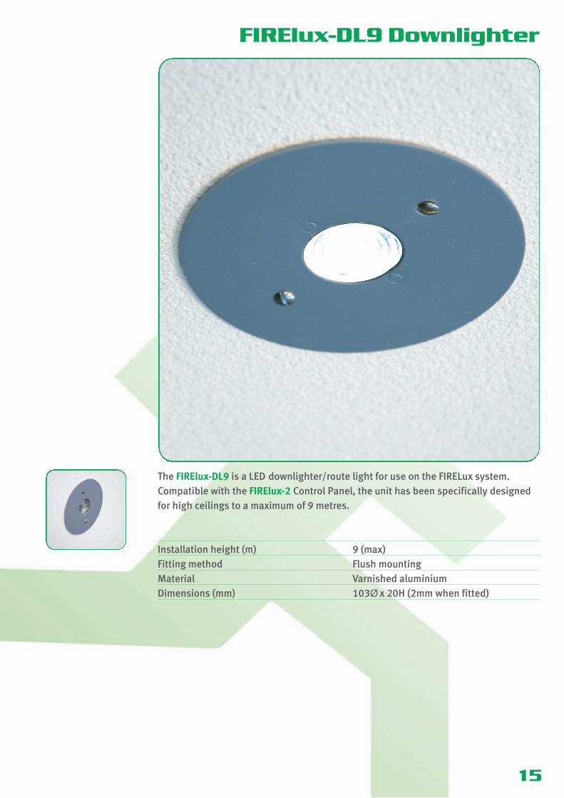
The FIRElux-DL9 is a LED downlighter/route light for use on the FIRELux system.Compatible with the FIRElux-2 Control Panel, the unit has been specifically designedfor high ceilings to a maximum of 9 metres.
Installation height (m) 9 (max)Fitting method Flush mountingMaterial Varnished aluminiumDimensions (mm) 103Ø x 20H (2mm when fitted)
FIRElux-DL9 Downlighter
15

16
An LED-based, addressable step lighting unit, which is installed in a standard singlegang electrical back box for a flush-fitting. This attractive and discreet unit is ideal forlighting stairways and changes in floor levels.
Material Fire resistant PC + ABS plastic (FR3010)Fire class UL94V-OOperation time 1 h/3 hDimensions (mm) 80W x 80H x 12D
FIRElux-SL Addressable Step Luminaire

17
A LED-based emergency downlight, designed to be discreet and blend in wherestandard GU10 mains-powered lighting exists. Virtually maintenance-free with alamp life of approximately 50,000 hours. Back-up battery packs are made of silicone-coated glass fibre sleeving and feature high temperature Nickel Cadmium batterycells.
Colour White / Brass / ChromeUnit dimensions (mm) 80Ø x 40DBattery pack dimensions (mm) 70Ø x 190LCut-out diameter (mm) 75
FIRElux-DL2

18
One of the smallest recessed LED-based emergency luminaires currently available,this uniquely designed unit features a specially developed LED driver and advancedthermal engineering techniques to dramatically reduce the LED operatingtemperature.
Two models are available, one specifically for corridor lighting offers an elongateddistribution pattern to efficiently illuminate the centre line of escape route corridorsand one offering a more traditional cone distribution pattern for use in open areas.
Colour WhiteDimensions (mm) 50Ø x 32D (22mm above ceiling)Cut-out diameter (mm) 40
FIRElux-DL3

19
FIRElux Accessories
FIRElux-PSUis a bus-controlled Power Supply,which operates with the FIREluxsystem.
u Switched-mode power sourceu Parallel connection for outputs
max. 2.5mm2
u Outputs: 12 Vd.c. / 24 Vd.c.(2 x 5 A)
u Batteries: 2 units, 7 Ah / 1 hr standby time
u Group-specific monitoring of emergency lighting
u Controlled using FIRElux-IO unitsu Designed for 12/24 lights
FIRElux-35Vis a transformer for the FIRElux-2emergency light control panel.
u 35 VAC, 220 VAu Output: 35 VAC / 220 VAu Protection class: IP44u Operational temperature: max.
30°Cu Wall installation: with four
screwsu Manufacturing class: SS
4270203 (EN60742)u Weight: 3.2 kg
FIRElux-PMis a phase control unit for zonemonitoring of the FIRElux panelsusing FIRElux-IO. The unit monitorsfor power outages. As soon as themains power is cut the unit instructsthe luminaires to begin to run ontheir backup batteries.
FIRElux-FSis ‘flag support’ type fixing for theemergency lighting exit signsFIRElux-20 and FIRElux-40.
FIRElux-CSis a ceiling support fixing for theemergency lighting exit signsFIRElux-20 and FIRElux-40.

20
FIRElux Accessories
FIRElux-BATis a rechargeable Lithium/Polymerback-up battery for use withluminaires and exit signs within theFIRElux range.
u 320 mAhu 7.4 Vu For use with FIRElux luminaires
and exit signsu Ideal for cold facilities, minimum
operating temperature -25oCu Provides the BS5266 minimum
3h backup time
FIRElux-1RCis a relay card for use with theFIRElux-2 Emergency Light ControlPanel.
u Equipped with one potential-freerelay output
u Control voltage 12 Vd.c.u Electricity consumption 37.5mA
(at 12 Vd.c.)u Dimensions: 50 x 37mm
FIRElux-BDCis a battery monitoring card for usewith the FIRElux-2 Emergency LightControl Panel.
FIRElux-EXPis an expansion unit used forexpanding the serial ports of theFIRElux-2 Emergency Light ControlPanel. The unit provides twoadditional ports, SER1 and SER2.
FIRElux-8RCis a relay card which adds 8 relayoutputs to the FIRElux-2 EmergencyLight Control Panel. Each outputcan be programmed with allnecessary functions, including linksto other systems. Upto 4 cards canbe connected to the panelsimultaneously.
u Provides 8 relay outputs 1A at 30V
u RS-485 channel connection (DIL-128)
u A total of 4 cards can be connected to the same channel
u Dimensions: 110 x 75 x 42mmu Fits to DIN rail
u The unit is used to prevent the deep discharge of the panel’s battery during long-duration (over 50h) power outages
u Provides two additional serial ports within the control panel
u Ports can be configured either as RS-232 or RS-485
u Four integral LEDs to indicate communications

21
FIRElux Accessories
FIRElux-IOis an I/O unit which is linked to thebus channel of the FIRElux-DLEmergency Light Control Panel, fromwhich it receives its operationalvoltage. The unit links startswitches and phase monitors to theFIRElux system.
u 4 inputsu Dimensions: 100 x 110 x 35mm
FIRElux-ISOLis an isolator device which shouldbe used when connecting externalequipment to the FIRElux-2Emergency Light Control Panel’sRS232 outputs, to avoid groundleakages.
FIRElux-LANis a network card, RS232 toethernet adapter, designed forconnecting the FIRElux-2 EmergencyLight Control Panel to anEthernet network.
u 10/100Mbit/su Operational voltage 9-30Vd.c.u Power feed from the FIRElux-2
Emergency Light Control Panel(PRG screw connector)
u Maximum distance from the panel is 200m
FIRElux-SWT5is a 5-port Ethernet switch whichcan be used for splitting an Ethernetnetwork and extending CAT cabling.
u RJ45 connectorsu Maximum distance to the next
switch or terminal unit 100mu 10/100Mbit/su Operational voltage 18.5 to
30.2Vd.c.u Electricity consumption ~ 90mA
(at 24Vd.c.)u For power feed HEDSAM POW5
FIRElux-SWT8is an 8-port Ethernet switch whichcan be used for splitting an Ethernetnetwork and extending CAT cabling.
u as per FIRElux-SWT5 above

22
FIRElux Accessories
FIRElux-MCis a media adaptor capable ofconverting a dual cable to Ethernetin order to extend an Ethernetnetwork across a dual cableconnection
u RJ45 connector for Ethernet / screw connector for dual cable
u Maximum distance 1500mu Installation in pairs (‘master’ and
‘slave’ units)u No MAC or IP addressesu Transfer capacity: 95Mbit/s/
200m ; 20Mbit/s/1500mu Operational voltage 5Vd.c.u Power consumption max 2Au HEDSAM POW5 for power feed
and voltage reducer SC-24/5
YBN-R/3is a common mounting base whichis used to mount the FIRElux rangeof luminaires and exit signs.
u Electronics freeu Stainless steel contactsu Takes 2.5mm2 cablesu Slim profile - only 8mmu Facility for remote indicator u Quick and easy ‘twist on’
connection
TCH-B100is a Hand Held Address Programmerdesigned to address the FIREluxrange of luminaires and exit signs.Designed to be light, robust andeasy to use it operates from a singlePP3 size battery which can provideover 8000 operations.(shown with luminaire fitted – not supplied)
u Lightweight designu Quick and reliable addressingu Over 8000 address settings from
one battery
FIRElux-DEis an external weather-proofenclosure designed to allow theexternal mounting of the FIRElux-DLdown light. The enclosure features10 knock-outs and provides aningress protection rating of IP67
u Robust designu Provides IP67 protectionu 10 knock-outs

23
FIRElux-IMPis an installation and programmingsoftware application which can beused to remotely program lightlevels, set up lighting areas, createinput and output parameters etc.
u Allows remote setting of light levels
u Access to Maintained or Non Maintained settings
u Control over system statusu Allows remote setting of input/
output parametersu Assists in fault findingu Allows uploading and
downloading of datau Assists in report generation
FIRElux Software
FIRElux-GRAPHis an alarm graphics software whichallows the end-user to visuallycheck on the status of the completeFIRElux system, down to individualpoint status.
u Fully integrated graphics package
u Individual point monitoringu Reports point status informationu Point interrogation and control
FIRElux-CABis a connection cable for usebetween the FIRElux-2 EmergencyLight Control Panel and a PC/laptop.
USB to Serialcable for use in conjunction with theFIRElux-CAB for connection toPCs/laptops that don’t feature aSerial Port.

24
FIRElux Photometric Data
MountingHeight (m)
1 LuxAxial to Wall
1 LuxAxial Spacing
Between
2.0 2.27 4.902.5 2.68 6.003.0 3.12 6.903.5 3.45 7.704.0 3.72 8.504.5 2.50 9.205.0 0.70 9.80
FIRElux-DL - Corridor Emergency Luminaire
FIRElux-DL9 - Down Light
MAINTAINED Open Area to 0.5 Lux
MountingHeight (m)
0.5 LuxSpacing to Wall
0.25 LuxSpacing Between
2.0 0.95 1.102.5 1.10 1.263.0 1.22 1.393.5 1.36 1.534.0 1.48 1.684.5 1.60 1.805.0 1.70 1.936.0 1.85 2.187.0 1.90 2.468.0 1.64 2.559.0 1.41 2.68
MAINTAINED 2m Wide Corridor
MountingHeight (m)
1.0 LuxSpacing to Wall
0.5 LuxSpacing Between
2.0 1.19 2.702.5 1.37 3.103.0 1.54 3.443.5 1.69 3.844.0 1.81 4.204.5 1.89 4.525.0 1.90 4.806.0 1.50 5.227.0 1.29 5.368.0 1.00 4.649.0 0.50 4.00
NON-MAINTAINED Open Area to 0.5 Lux
MountingHeight (m)
0.5 LuxSpacing to Wall
0.25 LuxSpacing Between
2.0 0.99 1.142.5 1.13 1.303.0 1.27 1.443.5 1.40 1.584.0 1.53 1.734.5 1.65 1.855.0 1.76 1.996.0 1.94 2.237.0 2.05 2.478.0 1.99 2.679.0 1.70 2.82
NON-MAINTAINED 2m Wide Corridor
MountingHeight (m)
1.0 LuxSpacing to Wall
0.5 LuxSpacing Between
2.0 1.21 2.802.5 1.41 3.203.0 1.58 3.583.5 1.75 3.964.0 1.89 4.324.5 1.99 4.665.0 1.06 4.986.0 1.86 5.507.0 1.51 5.808.0 1.30 5.649.0 1.00 4.80

25
FIRElux-DL2 - Down Light
NON-MAINTAINED Open Area to 0.5 Lux
MountingHeight (m)
Transverseto wall
Transversebetween
Axialto wall
Axialbetween
Transverseto axial
2.5 2.20 5.80 2.20 5.80 5.804.0 2.80 6.80 2.80 6.80 6.80
6.00 2.70 6.10 2.70 6.10 6.10
FIRElux-DL3 - Down Light
NON-MAINTAINED Open Area to 0.5 Lux
MountingHeight (m)
Transverseto wall
Transversebetween
Axialto wall
Axialbetween
Transverseto axial
2.5 1.40 6.80 1.40 6.80 6.803.0 6.00 6.00 6.00
4.00 1.40 1.40 1.40

26
Design GuideNON-MAINTAINED
The lighting only operateswhen the normal mainssupply fails (emergencylighting only).
MAINTAINED
The lighting operatesnormally and continues tooperate when the normalmains supply fails (mainslighting and emergencylighting only).
FINAL EXIT
To provide illumination ofescape routes.
Install within 2 metres ofescape route junctions.
Install within 2 metreshorizontal distance of a changeof direction in an escape route.
Install within 2 metreshorizontal distance of changein floor level or stairs (eachtread to receive direct light).
Install externally within 2metres horizontal distance ofany final exits. Please notethat sufficient light will beneeded to muster a roll call.
Fire alarms, first aid points andfire-fighting equipment, installwithin 2 metres horizontaldistance.
Should not be used as anescape route but requires thesame illumination to protectusers on it when the supplyfails.
Install in all toilets exceeding8m2 area or where natural lightis not present.
To provide emergencyilluminations in all lifts.
Motor generator, control andplant rooms for essential andsafety services.
Open rooms either with aparticular hazard, an escaperoute passing through or largerthan 60m2.
Areas of high risk should beilluminated to 10% of normallighting or 15 lux, whichever isgreater.
JUNCTIONS CORRIDORS STAIRWAYS
FINAL EXITS ALARM AREAS ESCALATORS TOILETS
LIFTS CONTROL ROOMS OPEN AREAS HAZARDOUS AREAS
Index
27
Automatic MonitoringBenefits of FIRElux 5Cabling 8Control Centre 8Control Station 9Design Guide 26Energy Consumption & CO2 Emissions 7Escape Route Corridors 5FIRElux-1RC Relay Card 20FIRElux-2 Addressable Control Panel 10FIRElux-20 Addressable Exit Sign 13FIRElux-35V Transformer 19FIRElux-40 Addressable Exit Sign 12FIRElux-8RC Relay Card 20FIRElux-BAT Rechargeable Battery 20FIRElux-BDC Battery Monitoring Card 20FIRElux-CAB 23FIRElux-CS Ceiling Support 19FIRElux-DE Downlighter Enclosure 22FIRElux-DL Addressable Downlighter 14FIRElux-DL2 Addressable Downlighter 17FIRElux-DL3 Addressable Downlighter 18FIRElux-DL9 Addressable Downlighter 15FIRElux-EXP Expansion Unit 20FIRElux-FS Flag Support 19FIRElux-GRAPH 23FIRElux-IMP 23FIRElux-IO Input/Output Unit 21FIRElux-ISOL Isolator Device 21FIRElux-KP Lighting System Keypad 11FIRElux-LAN Network Card 21FIRElux-MC Media Adaptor 22FIRElux Photometric Data 24, 25FIRElux-PM Phase Monitor 19FIRElux-PSU Power Supply 19FIRElux-SL Addressable Step Luminaire 16FIRElux-SWT5 5-Port Ethernet Switch 21FIRElux-SWT8 8-Port Ethernet Switch 21Greener Solution to Emergency Lighting 4GSM 9Operational Reliability 4Maintenance 8System Structure 8TCH-B100 22YBN-R/3 Mounting Base 22

Hochiki Europe (UK) Ltd. reserves the right to alter thespecification of its products from time to time withoutnotice. Although every effort has been made to ensure theaccuracy of the information contained in this document itis not warranted or represented by Hochiki Europe (UK)Ltd. to be a complete and up-to-date description.
HOCHIKI EUROPE (UK) LIMITEDGrosvenor Road, Gillingham Business ParkGillingham, Kent, ME8 0SA, United KingdomTelephone: +44 (0)1634 260133 Facsimile: +44 (0)1634 260132e-mail (UK): [email protected] (Non UK): [email protected]
Quality System Certificate No. 164 Assessed to ISO9001
Environmental Management SystemCertificate No. EMS 286Assessed to ISO 14001 : 1996
Learn more about the full FIRElux range atwww.firelux.co.uk
9-5-0-419/ISS2/JUN10