OG U10C017 U10C022 U10C034 OperationGuide Version … · Operation Guide Draft 1.1 July 2008 ......
104
U10C017/22/34 Telephony Operation Guide Version 1.1 Date: July 2008
Transcript of OG U10C017 U10C022 U10C034 OperationGuide Version … · Operation Guide Draft 1.1 July 2008 ......

U10C017/22/34
Telephony Operation Guide
Version 1.1 Date: July 2008

U10C017/22/34 Telephony Version 1.1 July 2007
ii
Operation Guide Draft 1.1 July 2008
iiiRevision History
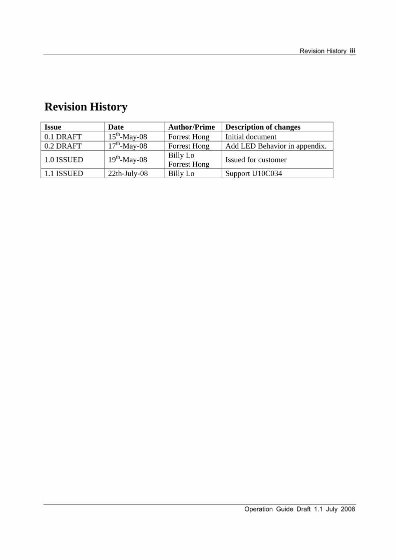
Revision History Issue Date Author/Prime Description of changes 0.1 DRAFT 15th-May-08 Forrest Hong Initial document 0.2 DRAFT 17th-May-08 Forrest Hong Add LED Behavior in appendix.
1.0 ISSUED 19th-May-08 Billy Lo Forrest Hong Issued for customer
1.1 ISSUED 22th-July-08 Billy Lo Support U10C034

U10C017/22/34 Telephony Version 1.1 July 2007
iv
Operation Guide Draft 1.1 July 2008
v
Contents
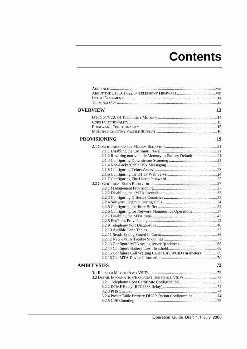
AUDIENCE ........................................................................................................ VIII ABOUT THE U10C017/22/34 TELEPHONY FIRMWARE ...................................... VIII IN THIS DOCUMENT ............................................................................................ IX TERMINOLOGY ................................................................................................... IX
OVERVIEW 13
U10C017/22/34 TELEPHONY MODEMS .......................................................... 14 CORE FUNCTIONALITY ...................................................................................... 15 FIRMWARE FUNCTIONALITY ............................................................................ 15 MULTIPLE COUNTRY PROFILE SUPPORT ............................................................ 16
PROVISIONING 19
2.1 CONFIGURING CABLE MODEM BEHAVIOR ................................................... 21 2.1.1 Disabling the CM miniFirewall ...................................................... 21 2.1.2 Resetting non-volatile Memory to Factory Default ........................ 21 2.1.3 Configuring Downstream Scanning ............................................... 21 2.1.4 Non-PacketCable DSx Messaging ................................................. 23 2.1.5 Configuring Telnet Access ............................................................. 23 2.1.6 Configuring the HTTP Web Server ................................................ 24 2.1.7 Configuring The User’s Password .................................................. 25
2.2 CONFIGURING EMTA BEHAVIOR .................................................................. 27 2.2.1 Management Provisioning .............................................................. 27 2.2.2 Disabling the eMTA firewall.......................................................... 33 2.2.3 Configuring Different Countries .................................................... 33 2.2.4 Software Upgrade During Calls ..................................................... 34 2.2.5 Configuring the Jitter Buffer .......................................................... 34 2.2.6 Configuring for Network Maintenance Operations ........................ 37 2.2.7 Disabling the MTA traps ................................................................ 42 2.2.8 EndPoint Provisioning .................................................................... 42 2.2.9 Telephony Port Diagnostics ........................................................... 46 2.2.10 Audible Tone Tables .................................................................... 53 2.2.11 Sends Syslog Stored In Cache ...................................................... 56 2.2.12 New eMTA Trouble Shootings .................................................... 57 2.2.13 Configure MTA syslog server Ip address. .................................... 68 2.2.14 Configure Battery Low Threshold ................................................ 69 2.2.15 Configure Call Waiting Caller ID(CWCID Parameters ............... 69 2.2.16 Get MTA Device Information ...................................................... 70
AMBIT VSIFS 72
3.1 RELATED MIBS TO AMIT VSIFS. ................................................................. 73 3.2 DETAIL INFORMATION/EXPLANATIONS TO ALL VSIFS. ............................... 73
3.2.1 Telephony Root Certificate Configuration ..................................... 73 3.2.2 DTMF Relay (RFC2833 Relay) ..................................................... 74 3.2.3 PHS Enable .................................................................................... 74 3.2.4 PacketCable Primary DHCP Option Configuration ....................... 74 3.2.5 CPE Counting ................................................................................. 75

U10C017/22/34 Telephony Version 1.1 July 2007
vi
3.2.6 DQOS Mode ................................................................................... 75 3.2.7 PowerSaving Interface Controller .................................................. 75 3.2.8 Buffer size for upstream queue for voice stream ............................ 76 3.2.9 Transmission Gain Configuration .................................................. 76 3.2.10 Receiving Gain Configuration ...................................................... 76 3.2.11 Software Download Configuration ............................................... 76 3.2.12 CLI Interface Configuration ......................................................... 77 3.2.13 SNMP Community for PacketCable SNMP Access .................... 77 3.2.14 PacketCable Provisioning Mode .................................................. 77 3.2.15 FQDN Verification Configuration ............................................... 78 3.2.16 PacketCable Configuration File Verification Configuration ........ 78 3.2.17 PacketCable Provisioning ............................................................. 78 3.2.18 PacketCable SNMP Source .......................................................... 78 3.2.19 PacketCable Secondary DHCP Option Configuration ................. 79 3.2.20 RTP Security Configuration ......................................................... 79 3.2.21 RTP TOS Configuration ............................................................... 79 3.2.22 MGCP CMS ................................................................................. 79 3.2.23 Crash Info ..................................................................................... 80 3.2.24 MGCP/NCS piggyback Configuration ......................................... 80 3.2.25 MTA Debug Level Configuration ................................................ 80 3.2.26 Console Input/Output Configuration ............................................ 81 3.2.28 Software reset when periodical Ranging-Abort ........................... 81 3.2.29 Service Flow control for voice stream .......................................... 81 3.2.30 Ignore MTA configure file hash check ......................................... 82 3.2.31 Control DOCSIS Security Download ........................................... 82
TELNET CLI 83
4.1 TIPS OF USING TELNET CLI ........................................................................ 84 4.1.1 Getting Help ................................................................................... 84 4.1.2 Redisplaying a command ............................................................... 85
4.2 CABLE MODEM TELNET COMMANDS .......................................................... 85 arp-storms ................................................................................................ 85 battery ...................................................................................................... 85 copy ......................................................................................................... 85 debug ....................................................................................................... 86 exec-timeout ............................................................................................ 86 goto_ds .................................................................................................... 86 interface ................................................................................................... 86 nvram ...................................................................................................... 87 ping .......................................................................................................... 88 passwd ..................................................................................................... 88 quit or exit ............................................................................................... 88 rmaccesslog ............................................................................................. 88 reset ......................................................................................................... 89 show ........................................................................................................ 89 telnet-access ............................................................................................ 90 web-access ............................................................................................... 91 tracert ...................................................................................................... 91 write ........................................................................................................ 91 emta-config ............................................................................................. 92
4.3 MTA TELNET COMMANDS .......................................................................... 92 copy ......................................................................................................... 92 countrycode ............................................................................................. 92 debug ....................................................................................................... 94 loopcurrent .............................................................................................. 96 ncs-queue-length ..................................................................................... 96

Operation Guide Draft 1.1 July 2008
vii
pktcsyslog ................................................................................................ 96 polarity .................................................................................................... 96 ring .......................................................................................................... 97 show ........................................................................................................ 97 volume ..................................................................................................... 99 exit ........................................................................................................... 99 reset ......................................................................................................... 99
U10C022 USER GUIDE 100
APPENDIX A:EMTA LED BEHAVIOR 102

U10C017/22/34 Telephony Version 1.1 July 2007
viii
About This Document
This document describes standards compliance, telephony features, and data features of U10C017/22/34 Telephony firmware, and how to manage it via MIBs/VSIFs/Telent-CLI.
Some features described in this document may not be fully tested and supported in your specific firmware release version. Where possible, features supported only by specific versions are indicated in this document. See the Release Notes/Letter of Operational Considerations accompanying your firmware for further details.
AUDIENCE
If you are evaluating U10C017/22/34 Telephony products for use in your VoIP network, you should read this entire manual.
This manual assumes that you have a basic understanding of DOCSIS and PacketCable standards, and a working knowledge of cable data and telephony networks.
ABOUT THE U10C017/22/34 TELEPHONY FIRMWARE U10C017/22/34 Telephony firmware provides operating, maintenance and trou-bleshooting functions for the following AMBIT eMTA:
• U10C017/22/34 Telephony Modem

Operation Guide Draft 1.1 July 2008
ix
IN THIS DOCUMENT This document contains the following information:
• Chapter 1, ‘‘Overview,’’ provides a brief overview of the U10C017/22/34 Operation Guide.
• Chapter 2, ‘‘Provisioning’’ gives a detail descriptions on Ambit/Broadcom private Mibs to show you how to use this modem, while which includes new features required by customer.
• Chapter 3, “Ambit VSIFs” outlines all supported VSIFs in current U10C017/22/34 firmware.
• Chapter 4, ‘‘Telnet CLI,’’ outlines all tenet commands of U10C017.
• Charpter4, “U10C022 User Guide” shows another documents about U10C022 Rg/Wireless features, users can refer to that document to get more information.
TERMINOLOGY The following is a list of terms and abbreviations used in this manual.
AckCel A Broadcom-proprietary protocol which is to increase TCP-based performance.
AES Advanced Encryption Standard. A symmetric 128-bit block cipher that has been adopted by the US Federal Government as its symmetric data encryption standard in October 2000, replacing the DES encryption it used.
CM Cable Modem. Typically a device installed at the subscriber premises that provides a high-speed data (Internet) connection through the HFC network.
CMS Call Management Server. A generic term for the devices connecting a VoIP network to the PSTN. A CMS includes both a Call Agent and the PSTN gateway, and controls audio call connections.

U10C017/22/34 Telephony Version 1.1 July 2007
x
CMTS Cable Modem Termination System. A device at a cable headend that connects to cable modems over an HFC network to an IP network.
CPE Customer Premises Equipment. Subscriber-owned equipment con-nected to the network. Technically, a cable modem, MTA, or eMTA falls into this category, although many operators do not designate them as such.
CODEC COder-DECoder. In VoIP products, one of several possible schemes of converting audio (i.e. a phone call) to digital data and vice versa. Attributes of a CODEC include fidelity (e.g. voice quality), bandwidth, and latency.
DOCSIS Data Over Cable Service Interface Specification. The interoperability standards used for data communications equipment on an HFC network.
DTMF Dual Tone Multi-Frequency. The tones generated by touching the keys on the phone are used for a variety of purposes including voice mail systems and voice messaging. Also known as Touchtone.
eMTA Embedded MTA. A device, such as the AMBIT U10C017/22/34 Telephony Modem, that contains both an MTA and a Cable Modem.
Euro-DOCSIS The European version of DOCSIS. Euro-DOCSIS specifies an 8 MHz downstream bandwidth (vs. 6 MHz for DOCSIS); other minor differences exist as well.
G.711 G.711 is an ITU-T standard for audio companding. It is primarily used in telephony. This audio standard is mandatory for all video conferencing systems. It requires a data rate of 56 or 64 kbit/s and provides an audio bandwidth of 300 ... 3400 Hz.
G.729 G.729 is an audio data compression algorithm for voice that compresses voice audio in chunks of 10 milliseconds. Music or tones such as DTMF or fax tones cannot be transported reliably with this codec, and thus use G.711 or out-of-band methods to transport these signals. Also very common is G.729a which is compatible with G.729, but requires less computation. This lower complexity is not free since speech quality is marginally worsened.
HFC Hybrid Fiber-Coaxial. A broadband, bi-directional shared media transmission system using fiber trunks between the headend and fiber nodes, and coaxial distribution cable between the fiber nodes and subscriber premises.

Operation Guide Draft 1.1 July 2008
xi
iLBC internet Low Bitrate Codec. The codec is designed for narrowband speech and operates either with 30ms or 20ms frame sizes. The bit rate is 13.3 kbit/s for 30 ms frames (400 bits per block) or 15.2 kbit/s for 20 ms frames (304 bits per block). The iLBC codec enables graceful speech quality degradation in the case of lost frames, which occurs in connection with lost or delayed IP packets.
MIB Management Information Base. The data representing the state of a managed object in an SNMP-based network management system.
MTA Multimedia Terminal Adapter. A subscriber premises device that contains the network interface, CODECs, and all signaling and encapsulation functions required for telephony support, CLASS features signaling, and QoS signaling. The MTA is an integral part of U10C017/22/34 Telephony embedded MTA (eMTA) products.
NCS Network Call Signaling. The PacketCable protocol used to control calls.
PacketCable A CableLabs-led initiative aimed at developing interoperable interface specifications for delivering advanced, real-time multimedia services over two-way cable plant.
PHS Payload Header Suppression. A technology used to describe the process of suppressing the repetitive portion of payload headers at sender and restoring the headers at the receiver.
QoS Quality of Service. An attribute of a Service Flow, defining limitations or guarantees for data rate, latency, and jitter.
Quarantine A state where an endpoint (phone line) may potentially buffer events. Events not quarantined are processed normally. Processing of quarantined events may be delayed, potentially indefinitely.
REN Ringer Equivalency Number. It is a somewhat arbitrary number which denotes the loading a telephone ringer has on the line

U10C017/22/34 Telephony Version 1.1 July 2007
xii
RF Radio Frequency
SHA-1 Secure Hash Algorithm. A one-way cryptographic function which takes a message procedures to a 160-bit message digest.
SNMP Simple Network Management Protocol.
TDD Telecommunication Device for the Deaf. An electronic device for text communication via a telephone line, used when one or more the parties has hearing or speech difficulties. Other names for TDD include TTY (Telephone TYpewriter), textphone (common in Europe), and minicom (U.K.).
VoIP Telephony over IP. The AMBIT implementation of PacketCable- compliant telephony services over an HFC network..
UGS Unsolicited Grant Service. A Service Flow type used for applications such as telephony in which latency and jitter are critical. Packets have a fixed size and interval. Within the constraints of IP networking, UGS flows attempt to deliver a constant bit rate stream of data.

Operation Guide Draft 1.1 July 2008
xiii
1
Overview
This chapter describes U10C017/22/34 Telephony hardware and firmware features.
U10C017/22/34 Telephony eMTA (also referred to as Embedded MTAs or eMTA), provide the subscriber connection to the HFC IP network.
U10C017/22/34 eMTA firmware complies to following standards:
• DOCSIS 1.1 and DOCSIS 2.0
• PacketCable 1.5

U10C017/22/34 Telephony Version 1.1 July 2007
14
U10C017/22/34 TELEPHONY MODEMS This section describes the Telephony Modems supported by the current release of U10C017/22/34 firmware. U10C017/22/34 Telephony Modems are the latest generation of AMBIT eMTA, providing improved technology and features. As with previous generations, U10C017/22/34 Telephony Modems provide telephony via MGCP, 10/100BaseT Ethernet and USB data connections.

Operation Guide Draft 1.1 July 2008
15
CORE FUNCTIONALITY
U10C017/22/34 firmware provides the following core functionality:
• Multiple provisioning methods.
• Support for up to 16 Upstream Service Flows (SIDs).
• Support for various packetization rates.
• Support of SNMP v1/v2c and v3 coexistence.
• CPE Ethernet — 10/100 BaseT / full-duplex / auto-negotiate function-ality.
• CPE USB — 1.1 fully supported
• USB to Ethernet bridging functionality
FIRMWARE FUNCTIONALITY The firmware provides the following functionality:
• Standards compatibility as follows:
– DOCSIS 2.0 and DOCSIS 1.1
– PacketCable 1.5
• Interoperability with main CMTS products.
• MGCP signaling protocol support
• PacketCable provisioning with SNMPv2 Network Management capabilities.
• Support USB and Ethernet interfaces to CPE.
• Support Telnet access to a troubleshooting command line interface.
• Support for automatically timing out Telnet sessions after a certain amount of idle time.
• Supports the AckCel technology, increasing performance of TCP application such as FTP.
U10C017/22/34 Telephony Version 1.1 July 2007
16
• Secure firmware downloading, conforming to the DOCSIS 1.1 specification.
• Support end of call statistics
• Country Code Profile Support
• Support Time Warner NCS VoIP eMTA Addendum to Vendor Product Requirements.
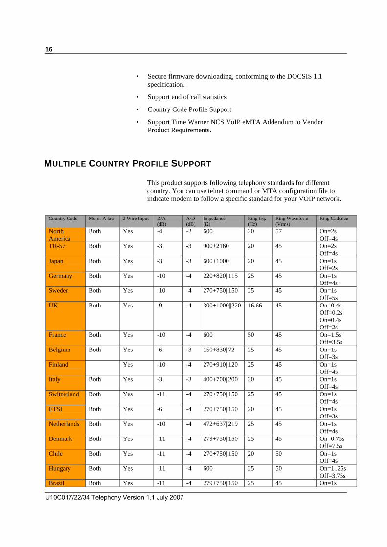
MULTIPLE COUNTRY PROFILE SUPPORT
This product supports following telephony standards for different country. You can use telnet command or MTA configuration file to indicate modem to follow a specific standard for your VOIP network.
Country Code Mu or A law 2 Wire Input D/A
(dB) A/D(dB)
Impedance (Ω)
Ring frq. (Hz)
Ring Waveform (Vrms)
Ring Cadence
North America
Both Yes -4 -2 600 20 57 On=2s Off=4s
TR-57 Both Yes -3 -3 900+2160 20 45 On=2s Off=4s
Japan Both Yes -3 -3 600+1000 20 45 On=1s Off=2s
Germany Both Yes -10 -4 220+820||115 25 45 On=1s Off=4s
Sweden Both Yes -10 -4 270+750||150 25 45 On=1s Off=5s
UK Both Yes -9 -4 300+1000||220 16.66 45 On=0.4s Off=0.2s On=0.4s Off=2s
France Both Yes -10 -4 600 50 45 On=1.5s Off=3.5s
Belgium Both Yes -6 -3 150+830||72 25 45 On=1s Off=3s
Finland
Yes -10 -4 270+910||120 25 45 On=1s Off=4s
Italy Both Yes -3 -3 400+700||200 20 45 On=1s Off=4s
Switzerland Both Yes -11 -4 270+750||150 25 45 On=1s Off=4s
ETSI Both Yes -6 -4 270+750||150 20 45 On=1s Off=3s
Netherlands Both Yes -10 -4 472+637||219 25 45 On=1s Off=4s
Denmark Both Yes -11 -4 279+750||150 25 45 On=0.75s Off=7.5s
Chile Both Yes -11 -4 270+750||150 20 50 On=1s Off=4s
Hungary Both Yes -11 -4 600 25 50 On=1..25s Off=3.75s
Brazil Both Yes -11 -4 279+750||150 25 45 On=1s

Operation Guide Draft 1.1 July 2008
17
Off=4s Austria Both Yes -6 -4 220+820||115 25 45 On=1s
Off=5s Porland Both Yes -6 -4 220+820||115 25 45 On=1s
Off=4sCzech Both Yes -6 -4 600 45 45 On=1s
Off=4s Slovakia Both Yes -6 -4 220+820||115 25 75 On=1s
Off=4s Ireland Both Yes -6 -4 270+750||150 25 45 On=0.4s
Off=0.2s On=0.4s Off=2s
Slovenia Both Yes -6 -4 270+750||150 20 45 On=1s Off=3s
Romania Both Yes -6 -4 270+750||150 20 45 On=1s Off=3s

U10C017/22/34 Telephony Version 1.1 July 2007
18

Operation Guide Draft 1.1 July 2008
19
2 Provisioning
Ambit/Broadcom private MIBs provide extensive support for configuring and controlling PacketCable NCS based eMTAs where additional functionality has been added to software above and beyond CableLabs and other industry specifications. Ambit and Broadcom’s private enterprise MIBs for Cable data products (1.3.6.1.4.1.4684/1.3.6.1.4.1.4413.2) currently consist of the class of devices adhering to Cablelabs and Excentis specifications for DOCSIS, PacketCable, and eDOCSIS based devices. Normally the MIB definitions themselves provide a good overview and enough information for understanding the purpose and how to control objects but additional details will be provided where appropriate. Throughout the descriptions to MIB objects are references to interfaces. Ambit’s software can support 8 IP stacks or interfaces. The assignments of IP addresses is different if an ePS is included in conjunction with an eMTA but for the purposes of this document the follow assignment shows the combined functionality of DOCSIS or a cable modem along with an eMTA:
• IP Stack (1) = Cable Modem’s public WAN IP address
• IP Stack (2) = eMTA public WAN IP address(For U10C017)
• IP Stack (6) = eMTA public WAN IP address(For U10C022)
• IP Stack (3) = Cable Modem’s private LAN IP address 192.168.100.1
Ambit CM Proprietary MIBS • Ambit-Cm-Mgmt.mib
• Ambit-Telnet-Mgmt.mib
• AMBIT-Web-Mgmt.mib

U10C017/22/34 Telephony Version 1.1 July 2007
20
• Ambit-User-Account-Mgmt.mib
Ambit eMTA Proprietary MIBS
• mtaMgmtMib.mib • mtaInformationMib.mib • mtaSecurityMib.mib • AmbitVSIFMib.mib • mtaCountrySpecific.mib • mtaPerCallMeasurements.mib • mtaRtpStatus.mib • mtaMgcpStatus.mib
Broadcom CM Proprietary MIBS
• brcm-ping-mgmt.mib
• brcm-bfc-mgmt.mib
• brcm-cm-mgmt-ext.mib
• brcm-cm-mgmt.mib
Broadcom eMTA Proprietary MIBS • brcm-emta-mgmt.mib

Operation Guide Draft 1.1 July 2008
21
2.1 CONFIGURING CABLE MODEM BEHAVIOR
2.1.1 Disabling the CM miniFirewall
brcm-cm-mgmt-ext.mib
MIB Default Value Access
cmMiniFirewallEnable true read-write cmMiniFirewallEnable (1.3.6.1.4.1.4413.2.2.2.1.2.1.3.0 Integer32)
This specifies whether the CM mini-firewall will be enabled, provided the mini-firewall feature is supported. If the feature is not supported, this object will always report false(2) and an attempt to set it to true(1) will be rejected with an inconsistent error.
2.1.2 Resetting non-volatile Memory to Factory Default
brcm-cm-mgmt-ext.mib
MIB Default Value Access
cmResetFactoryDefaults NA read-write cmResetFactoryDefaults (1.3.6.1.4.1.4413.2.2.2.1.2.1.6.0 Integer32) Setting this object to true(1) will cause the device to reset all non-volatile settings to their factory default state. Note that only dynamic settings will be affected; permanent settings (MAC addresses, etc) will remain unchanged. When read, this object always returns false(2)."
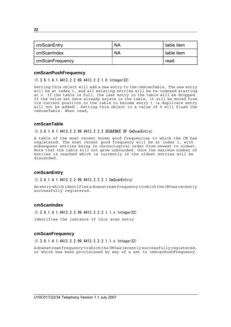
2.1.3 Configuring Downstream Scanning brcm-cm-mgmt-ext.mib
MIB Default Value Access
mScanPushFrequency NA read-write
cmScanTable NA table item
U10C017/22/34 Telephony Version 1.1 July 2007
22
cmScanEntry NA table item
cmScanIndex NA table item
cmScanFrequency read cmScanPushFrequency (1.3.6.1.4.1.4413.2.2.99.4413.2.2.1.0 Integer32) Setting this object will add a new entry to the cmScanTable. The new entry will be at index 1, and all existing entries will be re-indexed starting at 2. If the table is full, the last entry in the table will be dropped. If the value set here already exists in the table, it will be moved from its current position in the table to become entry 1 (a duplicate entry will not be added). Setting this object to a value of 0 will flush the cmScanTable. When read,
cmScanTable (1.3.6.1.4.1.4413.2.2.99.4413.2.2.2 SEQUENCE OF CmScanEntry) A table of the most recent known good frequencies to which the CM has registered. The most recent good frequency will be at index 1, with subsequent entries being in chronological order from newest to oldest. Note that the table will not grow unbounded. Once the maximum number of entries is reached which is currently 16 the oldest entries will be discarded.
cmScanEntry (1.3.6.1.4.1.4413.2.2.99.4413.2.2.2.1 CmScanEntry) An entry which identifies a downstream frequency to which the CM has recently successfully registered.
cmScanIndex (1.3.6.1.4.1.4413.2.2.99.4413.2.2.2.1.1.x Integer32)
Identifies the instance of this scan entry
cmScanFrequency (1.3.6.1.4.1.4413.2.2.99.4413.2.2.2.1.1.x Integer32)
A downstream frequency to which the CM has recently successfully registered, or which has been provisioned by way of a set to cmScanPushFrequency.
Operation Guide Draft 1.1 July 2008
23
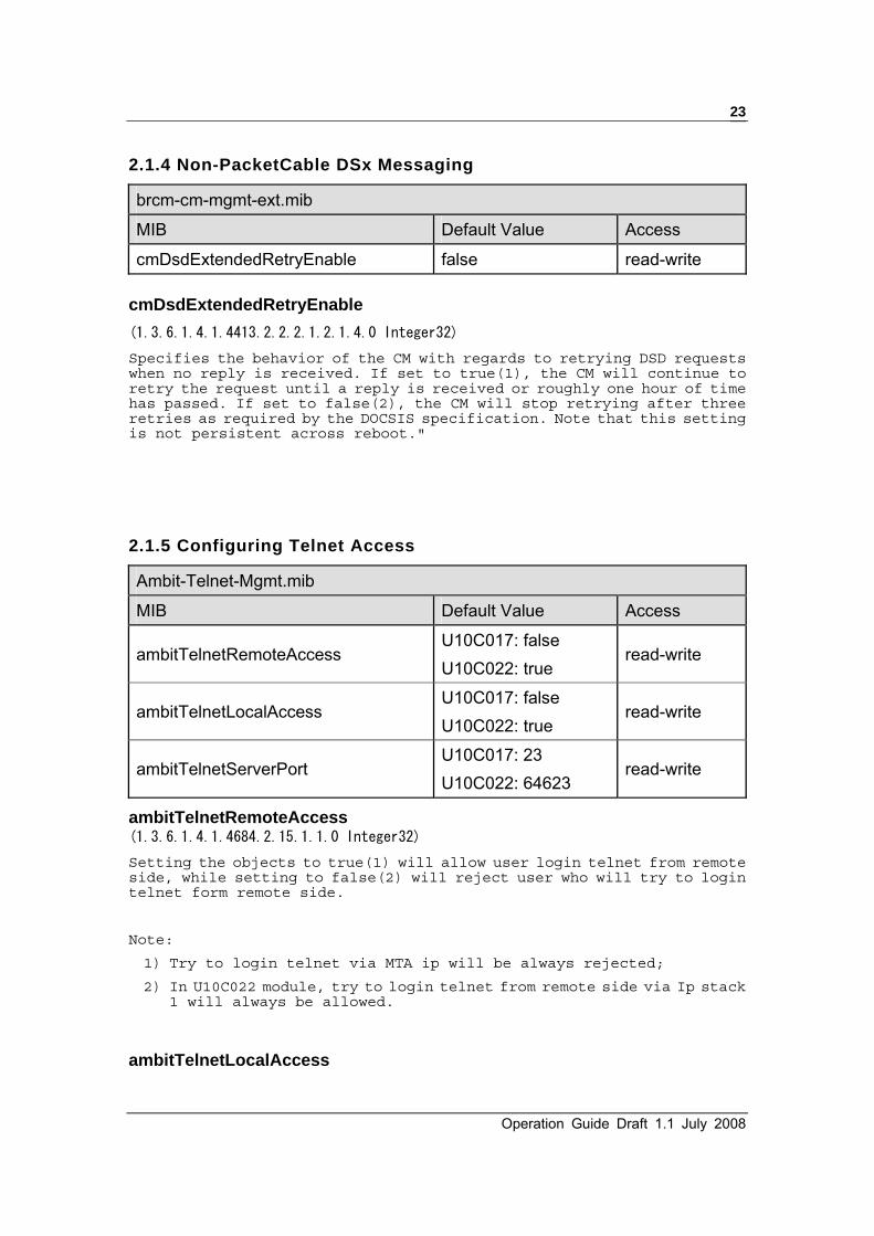
2.1.4 Non-PacketCable DSx Messaging
brcm-cm-mgmt-ext.mib
MIB Default Value Access
cmDsdExtendedRetryEnable false read-write cmDsdExtendedRetryEnable (1.3.6.1.4.1.4413.2.2.2.1.2.1.4.0 Integer32)
Specifies the behavior of the CM with regards to retrying DSD requests when no reply is received. If set to true(1), the CM will continue to retry the request until a reply is received or roughly one hour of time has passed. If set to false(2), the CM will stop retrying after three retries as required by the DOCSIS specification. Note that this setting is not persistent across reboot."
2.1.5 Configuring Telnet Access
Ambit-Telnet-Mgmt.mib
MIB Default Value Access
ambitTelnetRemoteAccess U10C017: false U10C022: true
read-write
ambitTelnetLocalAccess U10C017: false U10C022: true
read-write
ambitTelnetServerPort U10C017: 23 U10C022: 64623
read-write
ambitTelnetRemoteAccess (1.3.6.1.4.1.4684.2.15.1.1.0 Integer32) Setting the objects to true(1) will allow user login telnet from remote side, while setting to false(2) will reject user who will try to login telnet form remote side.
Note:
1) Try to login telnet via MTA ip will be always rejected; 2) In U10C022 module, try to login telnet from remote side via Ip stack
1 will always be allowed.
ambitTelnetLocalAccess

U10C017/22/34 Telephony Version 1.1 July 2007
24
(1.3.6.1.4.1.4684.2.15.1.2.0 Integer32) Setting the objects to true(1) will allow user login telnet from local, while setting to false(2) will reject user who will try to login telnet from local.
Note: Try to login telnet via MTA ip will be always rejected;
ambitTelnetServerPort (1.3.6.1.4.1.4684.2.15.1.3.0 Integer32) This object allows user to configure the listen port number of Telnet Serve.
Note:
1) The value of this object will persist across system reboot; 2) This value will take effect after system reboot; 3) This value can only be configured in U10C022 module. In U10C017,
its always returns 23 and are not writable.
2.1.6 Configuring the HTTP Web Server
Ambit-Telnet-Mgmt.mib
MIB Default Value Access
ambitWebRemoteAccess U10C017: false U10C022: true
read-write
ambitWebLocalAccess U10C017: false U10C022: true
read-write
ambitHttpServerPort U10C017: 80 U10C022: 64680
read-write
ambitWebRemoteAccess (1.3.6.1.4.1.4684.2.16.1.1.0 Integer32) Setting the objects to true(1) will allow user login web page from remote side, while setting to false(2) will reject user who will try to login web page form remote side.
ambitWebLocalAccess (1.3.6.1.4.1.4684.2.16.1.2.0 Integer32) Setting the objects to true(1) will allow user login web page from remote side, while setting to false(2) will reject user who will try to login

Operation Guide Draft 1.1 July 2008
25
web page form remote side.
ambitHttpServerPort (1.3.6.1.4.1.4684.2.16.1.3.0 Integer32) Configure the listen port number of Http Server. This MIB will be changed in RG/Trio modem. In Data Modem, this value will be read-only.
Note:
1) The value of this object will persist across system reboot; 2) This value will take effect after system reboot; 3) This value can only be configured in U10C022 module. In U10C017, its
always returns 80 and are not writable.
4) Using following two format to visit webpage
http://ModemWanIp:ambitHttpServerPort
http://ModemRfIp
2.1.7 Configuring The User’s Password
Ambit-User-Account-Mgmt.mib
MIB Default Value Access
ambitUserAccountTable N/A table item
ambitUserAccountEntry N/A table item
ambitUserAccountName user, admin read-only
ambitUserAccountPassword
User/password: user/user For U10C017 admin/admin For U10C022 admin/cableroot
read-write
ambitUserAccountTable (1.3.6.1.4.1.4684.2.17.1.1 SEQUENCE OF AmbitUserAccountEntry) A list of access user name and password pair. Currently, we support two user accounts, “user” and “admin”.

U10C017/22/34 Telephony Version 1.1 July 2007
26
ambitUserAccountEntry (1.3.6.1.4.1.4684.2.17.1.1.1 ambitUserAccountEntry) An entry which identifies the user account information.
ambitUserAccountName (1.3.6.1.4.1.4684.2.17.1.1.1.1.x DisplayString) Client user could use this user-name to access the telnet/web server, currently we supports two user accounts, “user” and “admin”.
ambitUserAccountPassword (1.3.6.1.4.1.4684.2.17.1.1.1.2.x DisplayString) Password of the corresponding user account, client user could use this password to access the telnet/web server
Operation Guide Draft 1.1 July 2008
27
2.2 CONFIGURING EMTA BEHAVIOR
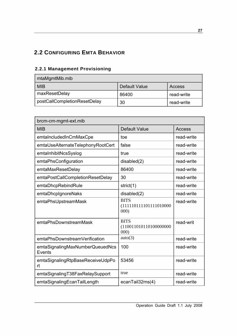
2.2.1 Management Provisioning
mtaMgmtMib.mib
MIB Default Value Access maxResetDelay 86400 read-write postCallCompletionResetDelay 30 read-write
brcm-cm-mgmt-ext.mib
MIB Default Value Access
emtaIncludedInCmMaxCpe toe read-write
emtaUseAlternateTelephonyRootCert false read-write
emtaInhibitNcsSyslog true read-write
emtaPhsConfiguration disabled(2) read-write
emtaMaxResetDelay 86400 read-write
emtaPostCallCompletionResetDelay 30 read-write
emtaDhcpRebindRule strict(1) read-write
emtaDhcpIgnoreNaks disabled(2) read-write
emtaPhsUpstreamMask BITS (111110111101111010000000)
read-write
emtaPhsDownstreamMask BITS (110011010110100000000000)
read-writ
emtaPhsDownstreamVerification auto(3) read-write
emtaSignalingMaxNumberQueuedNcsEvents
100 read-write
emtaSignalingRtpBaseReceiveUdpPort
53456 read-write
emtaSignalingT38FaxRelaySupport true read-write
emtaSignalingEcanTailLength ecanTail32ms(4) read-write

U10C017/22/34 Telephony Version 1.1 July 2007
28
emtaSignalingDQoSActivationModel twoPhase(2) read
emtaSignalingGR303Support disabled(2) read
emtaSignalingDefRtcpDSCP 0 read-write maxResetDelay/emtaMaxResetDelay (1.3.6.1.4.1.4684.36.1.1.6.0 Unsigned32)
(1.3.6.1.4.1.4413.2.2.2.1.6.1.11.0 Unsigned32) This object identifies the length of time, in seconds, that the MTA should wait after the software download for syslog event and reset there after. MTA will start a timer with this value after the completion of the SW download and an active phone call, upon expiry it will send an event notifying of the reset and restart the timer with the same value and upon second expiry MTA will be reset. This prevents software download reset from interrupting an active phone call. The default value of zero disables the reset delay and resets the unit immediately after the software download.
postCallCompletionResetDelay/emtaPostCallCompletionResetDelay (1.3.6.1.4.1.4684.36.1.1.7.0 Unsigned32)
(1.3.6.1.4.1.4413.2.2.2.1.6.1.12.0 Unsigned32) This object identifies the length of time, in seconds, that the MTA should wait after terminating a call before resetting the MTA if a reset is pending after the software download completion. The default value of zero disables the reset delay and reset the unit immediately after a software download.
emtaIncludedInCmMaxCpe (1.3.6.1.4.1.4413.2.2.2.1.6.1.4.0 Integer32) This object specifies whether the EMTA MAC address will be included when calculating the number of CPEs allowed by the CM as specified in the CM configuration file. Setting of the MIB takes effect on the next re-boot. Note that the eDOCSIS specification requires the value of this object to be true(1) and setting it to false(2) will violate the spec and render the device uncertifiable.
emtaUseAlternateTelephonyRootCert (1.3.6.1.4.1.4413.2.2.2.1.6.1.6.0 Integer32) This object controls which telephony root certificate the MTA will be using during its authentication phases. As per PacketCable 1.x, the telephony root certificate should be used so that it can be modified by way of a firmware upgrade if necessary. However, the alternate certificate may sometimes be required for testing, development, or other special situations. If set to true(1), the EMTA will use the alternate telephony root certificate provisioned in non-volatile storage. If set to false(2), the EMTA will use the telephony root certificate which is embedded in the firmware image.
emtaInhibitNcsSyslog

Operation Guide Draft 1.1 July 2008
29
(1.3.6.1.4.1.4413.2.2.2.1.6.1.8.0 Integer32) This object controls the logging of the NCS messages to Syslog. Generally, reporting of the events with NCS messages is following the PacketCable 1.x MEM Specification and Event MIB Specification. However, if this object has a value of true(1), logging of the NCS messages to syslog is inhibited. Otherwise, NCS logging control logic follows the requirements of the PacketCable 1.x Event MIB. The MTA must not persist this MIB object.
emtaPhsConfiguration (1.3.6.1.4.1.4413.2.2.2.1.6.1.10.0 Integer32)
This object controls the application of Payload Header Suppression (PHS) to voice RTP traffic. When disabled(1), PHS is not applied to either upstream or downstream RTP traffic. When enabled(2), PHS is applied to both upstream and downstream RTP traffic."
‧ enabled(1)
‧ disabled(2)
emtaDhcpRebindRule (1.3.6.1.4.1.4413.2.2.2.1.6.1.13.0 Integer32) This object is used to control the DHCP client behavior for the MTA when a DHCP REBIND (T2 timeout) occurs. The value strict(1) will only allow the MTA to accept a valid DHCP ACK only from the DHCP server that provided the initial lease. The value relaxed(2) will allow the MTA to accept a valid DHCP ACK from any DHCP server.
‧ strict(1)
‧ relaxed(2)
emtaDhcpIgnoreNaks (1.3.6.1.4.1.4413.2.2.2.1.6.1.14.0 Integer32) This object controls the DhcpIgnoreNaks Feature. When set to enabled(1) the mta dhcp client will ignore DHCP Naks when a line is offhook. When set to disabled(2) the mta DHCP client will operate normally.
‧ enabled(1),
‧ disabled(2)
emtaPhsUpstreamMask (1.3.6.1.4.1.4413.2.2.2.1.6.1.16.0 BITS) This object sets the PHS mask for upstream voice DQoS flows using IPv4 addressing. Setting a bit to '1' will cause the MTA to suppress this field for upstream voice flows.
The default configuration is all bits set except for ipTotalLength(5),
U10C017/22/34 Telephony Version 1.1 July 2007
30
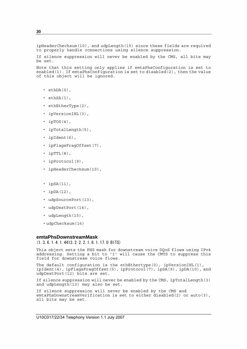
ipHeaderChecksum(10), and udpLength(15) since these fields are required to properly handle connections using silence suppression.
If silence suppression will never be enabled by the CMS, all bits may be set.
Note that this setting only applies if emtaPhsConfiguration is set to enabled(1). If emtaPhsConfiguration is set to disabled(2), then the value of this object will be ignored.
‧ ethDA(0),
‧ ethSA(1),
‧ ethEtherType(2),
‧ ipVersionIHL(3),
‧ ipTOS(4),
‧ ipTotalLength(5),
‧ ipIdent(6),
‧ ipFlagsFragOffset(7),
‧ ipTTL(8),
‧ ipProtocol(9),
‧ ipHeaderChecksum(10),
‧ ipSA(11),
‧ ipDA(12),
‧ udpSourcePort(13),
‧ udpDestPort(14),
‧ udpLength(15),
‧udpChecksum(16)
emtaPhsDownstreamMask (1.3.6.1.4.1.4413.2.2.2.1.6.1.17.0 BITS) This object sets the PHS mask for downstream voice DQoS flows using IPv4 addressing. Setting a bit to '1' will cause the CMTS to suppress this field for downstream voice flows.
The default configuration is the ethEthertype(0), ipVersionIHL(1), ipIdent(4), ipFlagsFragOffset(5), ipProtocol(7), ipSA(9), ipDA(10), and udpDestPort(12) bits are set.
If silence suppression will never be enabled by the CMS, ipTotalLength(3) and udpLength(13) may also be set.
If silence suppression will never be enabled by the CMS and emtaPhsDownstreamVerification is set to either disabled(2) or auto(3), all bits may be set.

Operation Guide Draft 1.1 July 2008
31
Note that this setting only applies if emtaPhsConfiguration is set to enabled(1). If emtaPhsConfiguration is set to disabled(2), then the value of this object will be ignored.
‧ ethEtherType(0),
‧ ipVersionIHL(1),
‧ ipTOS(2),
‧ ipTotalLength(3),
‧ ipIdent(4),
‧ ipFlagsFragOffset(5),
‧ ipTTL(6),
‧ ipProtocol(7),
‧ ipHeaderChecksum(8),
‧ ipSA(9),
‧ ipDA(10),
‧ udpSourcePort(11),
‧ udpDestPort(12),
‧ udpLength(13),
‧ udpChecksum(14)
emtaPhsDownstreamVerification (1.3.6.1.4.1.4413.2.2.2.1.6.1.18.0 Integer32) This object controls whether or not the MTA requests PHS verification (PHSV) by the CMTS on downstream PHS operations. The default is auto(3).
When set to auto(3), the MTA will automatically disable PHSV if the ipTOS(2), ipTTL(6), ipHeaderChecksum(8) or udpChecksum(14) bits are set in emtaPhsDownstreamMask.
When set to disabled(2), the MTA will disable PHSV at all times.
When set to enabled(1), the MTA will enable PHSV at all times.
This setting should be used with caution as it is possible to create a non-working configuration if verification is enabled and a non-predictable downstream field (e.g. ipTTL) is suppressed.
Note that this setting only applies if emtaPhsConfiguration is set to enabled(1). If emtaPhsConfiguration is set to disabled(2), then the value of this object will be ignored.
‧ enabled(1),
‧ disabled(2),
‧ auto(3)

U10C017/22/34 Telephony Version 1.1 July 2007
32
emtaSignalingMaxNumberQueuedNcsEvents (1.3.6.1.4.1.4413.2.2.2.1.6.4.10.0 Unsigned32) This object contains the max number of queued NCS events that the MTA can store during the lock step.
emtaSignalingRtpBaseReceiveUdpPort (1.3.6.1.4.1.4413.2.2.2.1.6.4.11.0 Unsigned32) This object contains the UDP Port Number used by the EMTA for RTP connection. RTP (and RTCP) ports for all connections will be based on this port.
emtaSignalingT38FaxRelaySupport (1.3.6.1.4.1.4413.2.2.2.1.6.4.14.0 Integer32) This object contains the value which controls the usage of the T38 Fax Relay. Setting this object to 'true(1)' causes the EMTA to use the T38 Fax Relay if supported by the DSP image. Setting this object to 'false(2)' causes the EMTA not to use T38 Fax Relay, but to use voice-band data mode for fax transmission instead.
emtaSignalingEcanTailLength (1.3.6.1.4.1.4413.2.2.2.1.6.4.15.0 Integer32) This object specifies the echo cancellation tail length. If the echo cancellation tail length is changed through SNMP, then those changes take effect starting with the next phone call (in process calls are not affected). Also note that the value of this object will persist across a MTA reset."
‧ ecanTail8ms(1)
‧ ecanTail16ms(2)
‧ ecanTail24ms(3)
‧ ecanTail32ms(4)
emtaSignalingDQoSActivationModel (1.3.6.1.4.1.4413.2.2.2.1.6.4.16.0 Integer32) This object controls the DQoS activation model. Setting this object to singlePhase(1) causes the eMTA to employ the single phase model where both reservation and commitment occur as a single autonomous operation. Setting this object to twoPhase(2) causes the eMTA to employ the two-phase model where the application reserves the resource, and later commits it. This object should only be changed by the configuration file.
‧ singlePhase(1)
‧ twoPhase(2)

Operation Guide Draft 1.1 July 2008
33
emtaSignalingGR303Support (1.3.6.1.4.1.4413.2.2.2.1.6.4.17.0 Integer32) Setting this object to enabled(1) causes the eMTA to switch to GR303 mode. The MTA will generate RTP on-hook event packets in the media stream until off-hook is detected or the connection is deleted. Also MTA will treat flash hook as separate on-hook and off-hook events, and send each event triple redundantly, replacing voice packets in the RTPstream. Setting this object to disabled(2) causes the eMTA not to use GR303 mode. This object should only be changed by the configuration file.
‧ enabled(1)
‧ disabled(2)
emtaSignalingDefRtcpDSCP (1.3.6.1.4.1.4413.2.2.2.1.6.4.23.0 Integer32) This object contains the default value used in the IP header for setting the DSCP for RTCP packets. When the value of this object is updated by SNMP, the MTA MUST use the new value as a default starting from the new connection. Existing connections are not affected by the value’s update.
2.2.2 Disabling the eMTA firewall (1.3.6.1.4.1.4413.2.2.2.1.6.1.2.0 Integer32) The eMTA stack has what is referred to as a lightweight firewall that has a default value of enabled (true), but can be set to disabled (false) when necessary.
brcm-cm-mgmt-ext.mib
MIB Default Value Access
emtaFirewallEnable true read-write
2.2.3 Configuring Different Countries
mtaCountrySpecific.mib
MIB Default Value Access
countryProfileCountryCode north_america(0) read-write countryProfileCountryCode (1.3.6.1.4.1.4684.36.1.6.1.0 Integer32)
This object contains the different country code, system will reboot after

U10C017/22/34 Telephony Version 1.1 July 2007
34
applying new value, and the value will be persisted while system reboot.
Valid options to given for this object are:
NORTH_AMERICA(0) JAPAN(1) UK(2) SWEDEN(3) GERMANY(4) FRANCE(5) TR57(6) BELGIUM(7) FINLAND(8) ITALY(9) ETSI(10) NETHERLANDS(11) SWITZERLAND(12) BRAZIL(13) DENMARK(14) HUNGARY(15) CHILE(16) POLAND(17)
2.2.4 Software Upgrade During Calls
brcm-cm-mgmt-ext.mib
MIB Default Value Access
emtaInhibitSwDownloadDuringCall False read-write emtaInhibitSwDownloadDuringCall (1.3.6.1.4.1.4413.2.2.2.1.6.1.1.0 Integer32) This object controls the processing logic of software downloading requests when there are specific telephony related EMTA activities. If this object has a value of true(1), DOCSIS software download by way of the docsDevSwAdminStatus MIB object will be inhibited if the value of esafeDevServiceIntImpact for the eMTA entry has a value of significant(1), indicating a call in progress. If docsDevSwAdminStatus is set to upgradeFromMgt(1) under these conditions, an error code of resourceUnavailable(13) will be returned and an appropriate event logged to the CM.
2.2.5 Configuring the Jitter Buffer There are 4 MIBs that constitute the control of the jitter buffer which can be configured as either fixed or adaptive by the emtaSignalingVoiceJitterBufferType MIB. The jitter buffer holds RTP frames for a configurable period of time in order to smooth out network jitter. In the case of a fixed jitter buffer the frames are held for a fixed period of time. A fixed jitter buffer with a high holding period is

Operation Guide Draft 1.1 July 2008
35
appropriate for VBD because delay is not as important as reducing packet loss, but in the case of voice calls where minimizing delay is more important than reducing packet loss an adaptive jitter buffer is appropriate. The adaptive jitter buffer adjusts the holding time as required based on the detected network jitter. The default values controlling the jitter buffer are for an adaptive jitter buffer with a maximum hold time of 200ms. The MIB default of 0 for emtaSignalingVoiceJitterBufferNomValue and emtaSignalingVoiceJitterBufferMinValue means they can adjust up to the maximum which is 200ms. The nominal hold time will be adjusted immediately when a voice call starts up. If you freeze the voice jitter buffer it uses the emtaSignalingVoiceJitterNomValue for the fixed size of the jitter buffer. There are three MIBs for configuring the jitter buffer: • emtaSignalingVoiceJitterNomValue
• emtaSignalingVoiceJitterMinValue
• emtaSignalingVoiceJitterMaxValue
brcm-emta-mgmt.mib
MIB Default Value Access
emtaSignalingVoiceJitterBufferType jitterBufferTypeAdaptive(2) read-write
emtaSignalingVoiceJitterNomValue 0 read-write
emtaSignalingVoiceJitterMinValue 0 read-write
emtaSignalingVoiceJitterMaxValue 0 read-write
emtaSignalingDataJitterNomValue 60 read-write
emtaSignalingDataJitterMaxValue 0 read-write
emtaStatsAvgJitterMeasurement - read
emtaStatsMaxJitterMeasurement - read emtaSignalingVoiceJitterBufferType (1.3.6.1.4.1.4413.2.2.2.1.6.4.3.0 Integer32) This object contains the type of the jitter buffer. Setting this object to jitterBufferTypeFixed(1) causes the eMTA to employ a fixed jitter buffer. Setting this object to jitterBufferTypeAdaptive(2) causes the eMTA to use an adaptive jitter buffer. If the jitter buffer type value is changed through SNMP, then those changes take affect starting with the next phone call (in process calls are not affected). When the voice jitter buffer is frozen it uses the emtaSignalingVoiceJitterNomValue for the fixed size of the jitter buffer."
‧ jitterBufferTypeFixed(1), ‧ jitterBufferTypeAdaptive(2)

U10C017/22/34 Telephony Version 1.1 July 2007
36
emtaSignalingVoiceJitterNomValue (1.3.6.1.4.1.4413.2.2.2.1.6.4.4.0 Unsigned32) If the voice jitter buffer value is changed through SNMP, then those changes take affect starting with the next phone call (in process calls are not affected). This MIB sets the target hold time for the voice jitter buffer in milliseconds. This is the initial hold time for the adaptive jitter buffer. The actual target holding time will adapt above or below this in response to observed network jitter. The MTA will reject all attempts to set the value which is not within the interval defined by the emtaSignalingVoiceJitterMinValue and emtaSignalingVoiceJitterMaxValue MIB Objects. When the jitter buffer is frozen, this MIB controls the static size of the voice jitter buffer. The default value is 0 which is interpreted as the maximum jitter buffer size for the product. emtaSignalingVoiceJitterMinValue (1.3.6.1.4.1.4413.2.2.2.1.6.4.5.0 Unsigned32) If the voice jitter buffer value is changed through SNMP, then those changes take affect starting with the next phone call (in process calls are not affected). This MIB sets the minimum hold time for the voice jitter buffer in milliseconds. The target hold time cannot take on a value below the minimum either through a MIB setting or through adaptation. That is, packets will be held in the jitter buffer for at least this duration (on average). When a packet is received late it may be held for less than this time.
emtaSignalingVoiceJitterMaxValue (1.3.6.1.4.1.4413.2.2.2.1.6.4.6.0 Unsigned32) If the voice jitter buffer value is changed through SNMP, then those changes take affect starting with the next phone call (in process calls are not affected). This MIB sets the maximum hold time for the voice jitter buffer in milliseconds. The maximum size of the jitter buffer is only relevant for an adaptive jitter buffer. The target hold time cannot take on a value greater than the maximum either through a MIB setting or through adaptation. On average, packets will not be held longer than this time. However, if a packet is received quite early it may be held longer than the max hold time. The default value is 0 which is interpreted as the maximum jitter buffer size for the product.
emtaSignalingDataJitterNomValue (1.3.6.1.4.1.4413.2.2.2.1.6.4.7.0 Unsigned32) If the jitter buffer value is changed through SNMP, then those changes take affect starting with the next phone call (in process calls are not affected). This object controls the hold time for a fixed VBD jitter buffer. The jitter buffer always fixes itself when VBD is detected and never adapts below this level, so this value serves as a minimum too. The default value is 60 msec..
emtaSignalingDataJitterMaxValue (1.3.6.1.4.1.4413.2.2.2.1.6.4.19.0 Unsigned32) If the voice buffer value is changed through SNMP, then those changes take affect starting with the next phone call (in process calls are not

Operation Guide Draft 1.1 July 2008
37
affected). This MIB sets the maximum hold time for the fixed VBD jitter buffer and is only relevant when emtaSignalingVoiceJitterBufferType is set to 'jitterbufferTypeFixed(1)'. The default value is 0 which is interpreted as the maximum jitter buffer size for the product.
emtaStatsAvgJitterMeasurement (1.3.6.1.4.1.4413.2.2.2.1.6.5.8.0 Unsigned32) This objects contains the average jitter measurements for the last 24 hours.
emtaStatsMaxJitterMeasurement (1.3.6.1.4.1.4413.2.2.2.1.6.5.9.0 Unsigned32)
This objects contains the maximum jitter measurements for the last 24 hours.
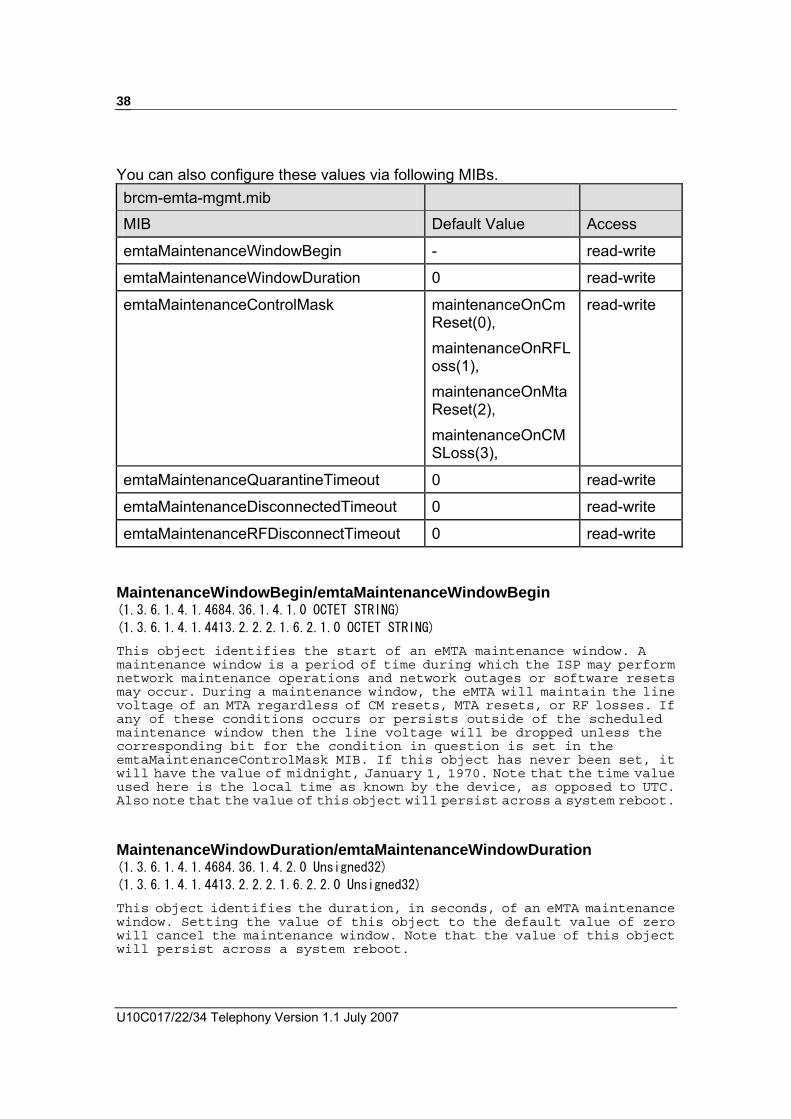
2.2.6 Configuring for Network Maintenance Operations The network maintenance operations provide control over the loop voltage behavior of the eMTA, and they can be done by either the private emtaMgmtMaintenance MIBs or the PacketCable pktcEnNcsEndPntLVMgmtTable MIBs. By default, the private MIBs are used. The PacketCable MIBs are used only for PacketCable 1.5 builds without vendor-specific build option.
mtaSecurityMib.mib
MIB Default Value Access
MaintenanceWindowBegin - read-write
MaintenanceWindowDuration 0 read-write
MaintenanceControlMask maintenanceOnCmReset(0), maintenanceOnRFLoss(1), maintenanceOnMtaReset(2), maintenanceOnCMSLoss(3),
read-write
MaintenanceQuarantineTimeout 0 read-write
MaintenanceDisconnectedTimeout 0 read-write
MaintenanceRFDisconnectTimeout 0 read-write
U10C017/22/34 Telephony Version 1.1 July 2007
38
You can also configure these values via following MIBs. brcm-emta-mgmt.mib
MIB Default Value Access
emtaMaintenanceWindowBegin - read-write
emtaMaintenanceWindowDuration 0 read-write
emtaMaintenanceControlMask maintenanceOnCmReset(0), maintenanceOnRFLoss(1), maintenanceOnMtaReset(2), maintenanceOnCMSLoss(3),
read-write
emtaMaintenanceQuarantineTimeout 0 read-write
emtaMaintenanceDisconnectedTimeout 0 read-write
emtaMaintenanceRFDisconnectTimeout 0 read-write MaintenanceWindowBegin/emtaMaintenanceWindowBegin (1.3.6.1.4.1.4684.36.1.4.1.0 OCTET STRING)
(1.3.6.1.4.1.4413.2.2.2.1.6.2.1.0 OCTET STRING) This object identifies the start of an eMTA maintenance window. A maintenance window is a period of time during which the ISP may perform network maintenance operations and network outages or software resets may occur. During a maintenance window, the eMTA will maintain the line voltage of an MTA regardless of CM resets, MTA resets, or RF losses. If any of these conditions occurs or persists outside of the scheduled maintenance window then the line voltage will be dropped unless the corresponding bit for the condition in question is set in the emtaMaintenanceControlMask MIB. If this object has never been set, it will have the value of midnight, January 1, 1970. Note that the time value used here is the local time as known by the device, as opposed to UTC. Also note that the value of this object will persist across a system reboot.
MaintenanceWindowDuration/emtaMaintenanceWindowDuration (1.3.6.1.4.1.4684.36.1.4.2.0 Unsigned32)
(1.3.6.1.4.1.4413.2.2.2.1.6.2.2.0 Unsigned32) This object identifies the duration, in seconds, of an eMTA maintenance window. Setting the value of this object to the default value of zero will cancel the maintenance window. Note that the value of this object will persist across a system reboot.

Operation Guide Draft 1.1 July 2008
39
MaintenanceControlMask/emtaMaintenanceControlMask (1.3.6.1.4.1.4684.36.1.4.3.0 BITS)
(1.3.6.1.4.1.4413.2.2.2.1.6.2.3.0 BITS) This object identifies the bit mask to control the line voltage behavior of the eMTA in various scenarios: maintenanceOnCmReset(0) - if this bit is set to 1 it requires the line voltage be maintained in the case when the CM has been reset, regardless of the reason (reset after downloading a new firmware, or hard reboot, or SNMP induced CM reset), and regardless of whether the MTA is in a valid maintenance window maintenanceOnRFLoss(1) - if this bit is set to 1 it requires the line voltage be maintained in the case when RF communication is lost, regardless of the reason, and regardless of whether the MTA is in a valid maintenance window maintenanceOnMtaReset(2) - if this bit is set to 1 it requires the line voltage be maintained in the case when the eMTA is being reset, regardless of the reason (e.g. SNMP induced eMTA reset, etc), and regardless of whether the MTA is in a valid maintenance window maintenanceOnCMSLoss(3) - if this bit is set to 1 it requires the line voltage be maintained in the case when communication is lost with the CMS, regardless of the reason (e.g. endpoint disconnected, etc), and regardless of whether the duration of the communication loss has exceeded the value in the MIB emtaMaintenanceQuarantineTimeout and/or emtaMaintenanceDisconnectedTimeout.
The default value of this object may change based on build specific options. However, it's highly recommended that the default value in the image submitted for (E)PC 1.x Certification be chosen in such a way that it will correspond to the functionality compliant with the PacketCable requirements and will preserve the backward compatibility with the previously certified behavior. Note that to satisfy the latter, 'maintenanceOnCMSLoss(3)' bit should be set by default.
‧ maintenanceOnCmReset(0), ‧ maintenanceOnRFLoss(1), ‧ maintenanceOnMtaReset(2), ‧ maintenanceOnCMSLoss(3)
MaintenanceQuarantineTimeout/emtaMaintenanceQuarantineTimeout (1.3.6.1.4.1.4684.36.1.4.4.0 Unsigned32)
(1.3.6.1.4.1.4413.2.2.2.1.6.2.4.0 Unsigned32) This object identifies the length of time, in seconds, that the MTA should maintain the line voltage after any of the endpoints enters the quarantine state. If any of the endpoints remains in the quarantine state for longer than this period the line voltage is dropped unless the maintenanceOnCMSLoss bit is set in the emtaMaintenanceControlMask MIB. Note that the value of this object will persist across a system reboot.
MaintenanceDisconnectedTimeout/emtaMaintenanceDisconnectedTimeout (1.3.6.1.4.1.4684.36.1.4.5.0 Unsigned32)
(1.3.6.1.4.1.4413.2.2.2.1.6.2.5.0 Unsigned32) This object identifies the length of time, in seconds, that the MTA should maintain the line voltage after any of the endpoints is disconnected.

U10C017/22/34 Telephony Version 1.1 July 2007
40
If any of the endpoints remains disconnected for longer than this period the line voltage is dropped unless the maintenanceOnCMSLoss bit is set in the emtaMaintenanceControlMask MIB. Note that the value of this object will persist across a system reboot.
MaintenanceRFDisconnectTimeout/emtaMaintenanceRFDisconnectTimeout (1.3.6.1.4.1.4684.36.1.4.6.0 Unsigned32)
(1.3.6.1.4.1.4413.2.2.2.1.6.2.6.0 Unsigned32) This object identifies the length of time, in seconds, that the MTA should maintain the line voltage after the RF lock with the CMTS is lost. If the MTA remains disconnected from the CMTS for longer than this period the line voltage is dropped unless the maintenanceOnRFLoss bit is set in the emtaMaintenanceControlMask MIB. Note that the value of this object will persist across a system reboot.
Differences between the private MIB feature and the PacketCable MIB feature: • Private MIBs allow one or more of the conditions of CM reset, RF
loss, MTA reset, and CMS loss to be configured. The configurability for CMS Loss is not available for PacketCable MIBs.
• The pktcEnNcsEndPntLVMgmtResetTimer applies to all the conditions of CM reset, RF loss, MTA reset, and CMS loss. The timers (the timeout MIBs) from private MIBs can apply to individual condition for CMS loss and RF loss, but there is no timer specific to CM reset and MTA reset.
• In the event of a RF Loss, the PacketCable MIB feature will complete a full scan on the spectrum after the T4 timeout before dropping the line voltage. The Private MIB feature will drop the line voltage as soon as there is a T4 timeout.
• The PacketCable MIBs provide control on whether line voltage should be maintained if MTA fails provisioning. The Private MIBs do not.
• The PacketCable MIBs provide control on the reset timer value for CM reset and MTA reset. The Private MIBs do not.
PacketCable Policy
PacketCable Timers emtaMaintenanceControlMask emtaMaintenance Timers
Policy 1 None OnCmReset(0),
OnRFLoss(1),
OnMtaReset(2),
OnCMSLoss(3)
None
Policy 2 None OnCmReset(0),
OnMtaReset(2),
OnCMSLoss(3)
emtaMaintenanceRF- DisconnectTimeout
Operation Guide Draft 1.1 July 2008
41
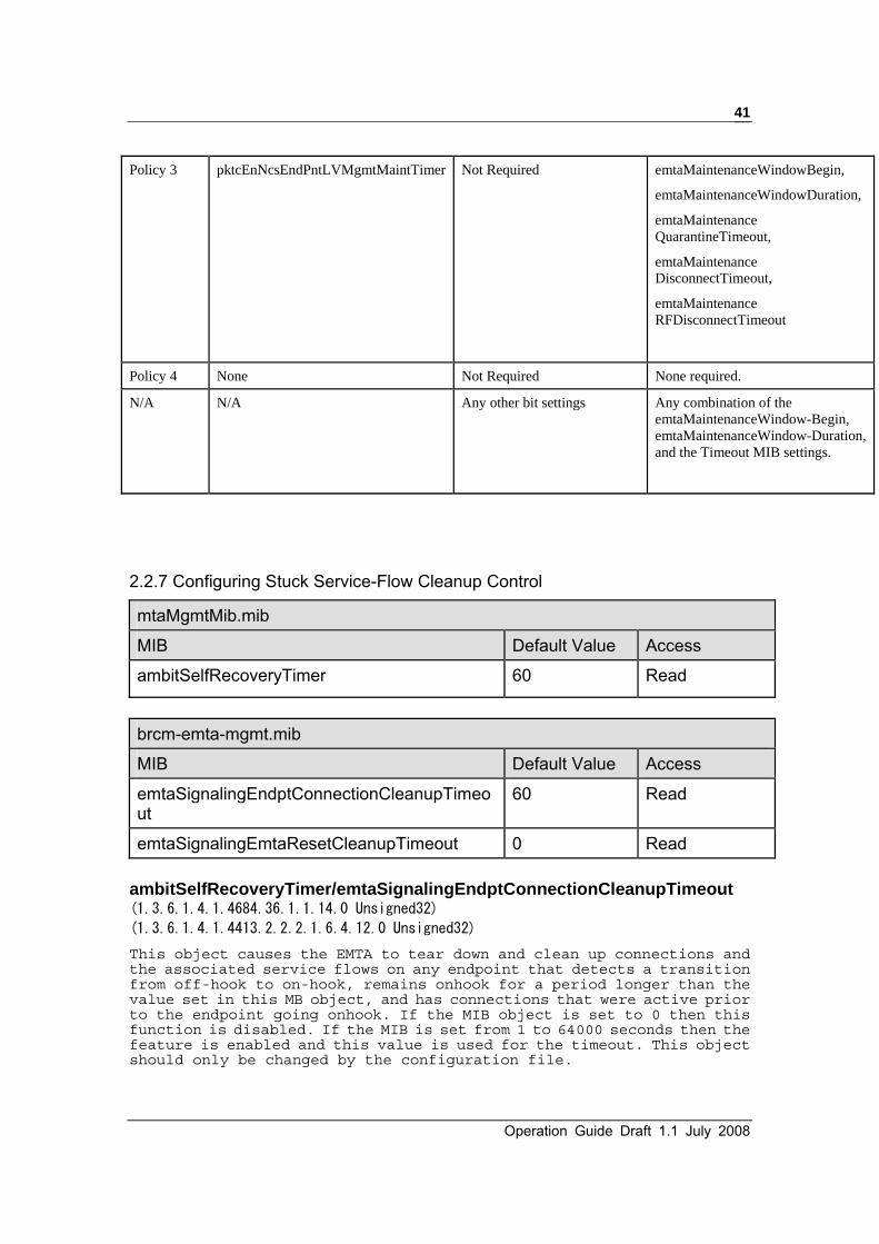
Policy 3 pktcEnNcsEndPntLVMgmtMaintTimer Not Required emtaMaintenanceWindowBegin,
emtaMaintenanceWindowDuration,
emtaMaintenance QuarantineTimeout,
emtaMaintenance DisconnectTimeout,
emtaMaintenance RFDisconnectTimeout
Policy 4 None Not Required None required.
N/A N/A Any other bit settings Any combination of the emtaMaintenanceWindow-Begin, emtaMaintenanceWindow-Duration, and the Timeout MIB settings.
2.2.7 Configuring Stuck Service-Flow Cleanup Control
mtaMgmtMib.mib
MIB Default Value Access
ambitSelfRecoveryTimer 60 Read
brcm-emta-mgmt.mib
MIB Default Value Access
emtaSignalingEndptConnectionCleanupTimeout
60 Read
emtaSignalingEmtaResetCleanupTimeout 0 Read ambitSelfRecoveryTimer/emtaSignalingEndptConnectionCleanupTimeout (1.3.6.1.4.1.4684.36.1.1.14.0 Unsigned32)
(1.3.6.1.4.1.4413.2.2.2.1.6.4.12.0 Unsigned32)
This object causes the EMTA to tear down and clean up connections and the associated service flows on any endpoint that detects a transition from off-hook to on-hook, remains onhook for a period longer than the value set in this MB object, and has connections that were active prior to the endpoint going onhook. If the MIB object is set to 0 then this function is disabled. If the MIB is set from 1 to 64000 seconds then the feature is enabled and this value is used for the timeout. This object should only be changed by the configuration file.

U10C017/22/34 Telephony Version 1.1 July 2007
42
emtaSignalingEmtaResetCleanupTimeout (1.3.6.1.4.1.4413.2.2.2.1.6.4.13.0 Unsigned32) This object causes the entire EMTA to reset if voice connections have been active and both voice lines have been on-hook for a period greater than the value defined via this MIB object. This will guarantee that orphaned connections and/or service flows are properly cleaned up and freed when the CMTS and CMS fail to perform the correct clean up operations. It will also ensure that the EMTA state machine, DSP voice channels, NCS connection handling, etc. are also restored to a default state. This protects against any unknown case that could possibly cause stuck service flows and/or connections. If the MIB object is set to 0 then this function is disabled. If the MIB is set from 1 to 64000 minutes then the feature is enabled and this value is used for the timeout. This object should only be changed by the configuration file.
2.2.7 Disabling the MTA traps
mtaMgmtMib.mib
MIB Default Value Access
trapEnable true read-write
trapEnable (1.3.6.1.4.1.4684.36.1.1.9.0 Integer32) Enable/Disable traps, set this object to enable(1) will enable traps generation, while set to disable(2) will disable traps generation.
2.2.8 EndPoint Provisioning
mtaMgmtMib.mib
MIB Default Value Access ambitTxRxGainTable N/A table item
ambitTxRxGainEntry N/A table item
endpointNumber - not-accessible
ambitTxGain -6 read-write
AmbitRxGain -6 read-write
brcm-emta-mgmt.mib
MIB Default Value Access
Operation Guide Draft 1.1 July 2008
43
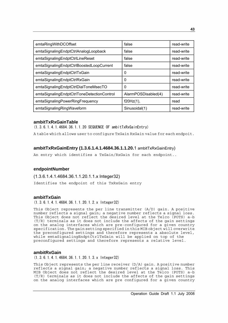
emtaRingWithDCOffset false read-write
emtaSignalingEndptCtrlAnalogLoopback false read-write
emtaSignalingEndptCtrlLineReset false read-write
emtaSignalingEndptCtrlBoostedLoopCurrent false read-write
emtaSignalingEndptCtrlTxGain 0 read-write
emtaSignalingEndptCtrlRxGain 0 read-write
emtaSignalingEndptCtrlDialToneMsecTO 0 read-write
emtaSignalingEndptCtrlToneDetectionControl AlarmPOSDisabled(4) read-write
emtaSignalingPowerRingFrequency f20Hz(1), read
emtaSignalingRingWaveform Sinusoidal(1) read-write
ambitTxRxGainTable (1.3.6.1.4.1.4684.36.1.1.20 SEQUENCE OF ambitTxRxGainEntry) A table which allows user to configure TxGain RxGain value for each endpoit.
ambitTxRxGainEntry (1.3.6.1.4.1.4684.36.1.1.20.1 ambitTxRxGainEntry) An entry which identifies a TxGain/RxGain for each endpoint..
endpointNumber (1.3.6.1.4.1.4684.36.1.1.20.1.1.x Integer32) Identifies the endpoint of this TxRxGain entry
ambitTxGain (1.3.6.1.4.1.4684.36.1.1.20.1.2.x Integer32) This Object represents the per line transmitter (A/D) gain. A positive number reflects a signal gain; a negative number reflects a signal loss. This Object does not reflect the desired level at the Telco (POTS) a-b (T/R) terminals as it does not include the affects of the gain settings on the analog interfaces which are pre-configured for a given country specification. The gain setting specified in this MIB object will overwrite the preconfigured settings and therefore represents a absolute level, while emtaSignalingEndptCtrlTxGain will be applied on top of the preconfigured settings and therefore represents a relative level.
ambitRxGain (1.3.6.1.4.1.4684.36.1.1.20.1.3.x Integer32) This Object represents the per line receiver (D/A) gain. A positive number reflects a signal gain; a negative number reflects a signal loss. This MIB Object does not reflect the desired level at the Telco (POTS) a-b (T/R) terminals as it does not include the affects of the gain settings on the analog interfaces which are pre configured for a given country

U10C017/22/34 Telephony Version 1.1 July 2007
44
specification. The gain setting specified in this MIB will overwrite the preconfigured settings and therefore represents a absolute level, while emtaSignalingEndptCtrlRxGain will be applied on top of the preconfigured settings and therefore represents a relative level. emtaRingWithDCOffset (1.3.6.1.4.1.4413.2.2.2.1.6.1.3.0 Integer32) This object specifies whether the ring with DC offset option is enabled.
emtaSignalingEndptCtrlAnalogLoopback (1.3.6.1.4.1.4413.2.2.2.1.6.4.1.1.1.x Integer32) This object controls the implementation of the analog loopback by the MTA. When the object is set to true(1), the MTA MUST implement analog loopback operations. When the object is set to false(2), the MTA MUST stop loopback operations immediately. The default value of this object corresponds to the functionality compliant with the PacketCable requirements.
emtaSignalingEndptCtrlLineReset (1.3.6.1.4.1.4413.2.2.2.1.6.4.1.1.2.x Integer32) This object controls the resetting the telephone line. Setting this object to true(1) causes the eMTA to reset the telephone line of the corresponding endpoint. Setting this object to false(2) does not have any affect. Reading this object always returns 'false(2)'.
emtaSignalingEndptCtrlBoostedLoopCurrent (1.3.6.1.4.1.4413.2.2.2.1.6.4.1.1.8.x Integer32) This object indicates whether the loop current should be boosted (true(1)) or not (false(2)). The particular value for the loop current depends on the particular hardware (SLIC) being used.
emtaSignalingEndptCtrlTxGain (1.3.6.1.4.1.4413.2.2.2.1.6.4.1.1.9.x Integer32) This Object represents the per line transmitter (A/D) gain. A positive number reflects a signal gain; a negative number reflects a signal loss. This Object does not reflect the desired level at the Telco (POTS) a-b (T/R) terminals as it does not include the affects of the gain settings on the analog interfaces which are pre-configured for a given country specification. The gain setting specified in this MIB object will be applied on top of the preconfigured settings and therefore represents a relative level, while ambitTxGain will overwrite the preconfigured settings and represents a absolute level.
emtaSignalingEndptCtrlRxGain (1.3.6.1.4.1.4413.2.2.2.1.6.4.1.1.10.x Integer32) This Object represents the per line receiver (D/A) gain. A positive number reflects a signal gain; a negative number reflects a signal loss. This
Operation Guide Draft 1.1 July 2008
45
MIB Object does not reflect the desired level at the Telco (POTS) a-b (T/R) terminals as it does not include the affects of the gain settings on the analog interfaces which are pre configured for a given country specification. The gain setting specified in this MIB will be applied on top of the preconfigured settings and therefore represents a relative level, while ambitRxGain will overwrite the preconfigured settings and represents a absolute level
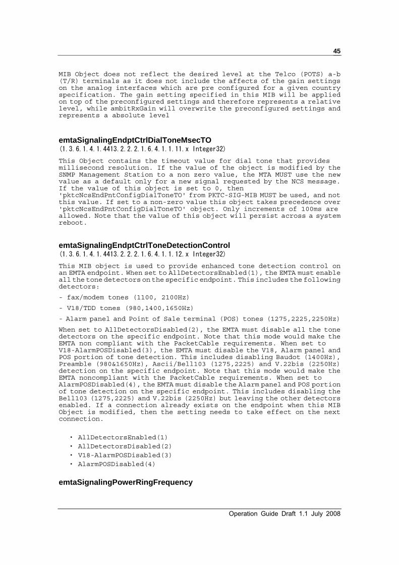
emtaSignalingEndptCtrlDialToneMsecTO (1.3.6.1.4.1.4413.2.2.2.1.6.4.1.1.11.x Integer32) This Object contains the timeout value for dial tone that provides millisecond resolution. If the value of the object is modified by the SNMP Management Station to a non zero value, the MTA MUST use the new value as a default only for a new signal requested by the NCS message. If the value of this object is set to 0, then 'pktcNcsEndPntConfigDialToneTO' from PKTC-SIG-MIB MUST be used, and not this value. If set to a non-zero value this object takes precedence over 'pktcNcsEndPntConfigDialToneTO' object. Only increments of 100ms are allowed. Note that the value of this object will persist across a system reboot.
emtaSignalingEndptCtrlToneDetectionControl (1.3.6.1.4.1.4413.2.2.2.1.6.4.1.1.12.x Integer32) This MIB object is used to provide enhanced tone detection control on an EMTA endpoint. When set to AllDetectorsEnabled(1), the EMTA must enable all the tone detectors on the specific endpoint. This includes the following detectors:
- fax/modem tones (1100, 2100Hz)
- V18/TDD tones (980,1400,1650Hz)
- Alarm panel and Point of Sale terminal (POS) tones (1275,2225,2250Hz)
When set to AllDetectorsDisabled(2), the EMTA must disable all the tone detectors on the specific endpoint. Note that this mode would make the EMTA non compliant with the PacketCable requirements. When set to V18-AlarmPOSDisabled(3), the EMTA must disable the V18, Alarm panel and POS portion of tone detection. This includes disabling Baudot (1400Hz), Preamble (980&1650Hz), Ascii/Bell103 (1275,2225) and V.22bis (2250Hz) detection on the specific endpoint. Note that this mode would make the EMTA noncompliant with the PacketCable requirements. When set to AlarmPOSDisabled(4), the EMTA must disable the Alarm panel and POS portion of tone detection on the specific endpoint. This includes disabling the Bell103 (1275,2225) and V.22bis (2250Hz) but leaving the other detectors enabled. If a connection already exists on the endpoint when this MIB Object is modified, then the setting needs to take effect on the next connection.
‧ AllDetectorsEnabled(1) ‧ AllDetectorsDisabled(2) ‧ V18-AlarmPOSDisabled(3) ‧ AlarmPOSDisabled(4)
emtaSignalingPowerRingFrequency

U10C017/22/34 Telephony Version 1.1 July 2007
46
(1.3.6.1.4.1.4413.2.2.2.1.6.4.18.0 Integer32) This object must only be provided via the configuration file during the provisioning process. The power ring frequency is the frequency at which the sinusoidal voltage must travel down the twisted pair to make terminal equipment ring. Different countries define different electrical characteristics to make terminal equipment ring.
‧ f20Hz(1) ‧ f25Hz(2) ‧ f33Point33Hz(3) ‧ f50Hz(4) ‧ f15Hz(5) ‧ f16Hz(6) ‧ f22Hz(7) ‧ f23Hz(8) ‧ f45Hz(9) ‧ f17Hz(10)
emtaSignalingRingWaveform (1.3.6.1.4.1.4413.2.2.2.1.6.4.20.0 Integer32) This MIB object is controls the shape of the ring waveform. The setting of sinusoidal(1) would result in a sinusoidal ring waveform with crest factor of 1.414, while the setting of trapezoidal(2) would result in a trapezoidal ring waveform with crest factor of 1.25.
‧ Sinusoidal(1) ‧ Trapezoidal(2)
2.2.9 Telephony Port Diagnostics TPD testing can be used to diagnose problems with customer cabling, terminations and unexpected foreign voltages sources. Testing encompasses the ability to detect the hook state, the ability to communicate with a CMS, detect shorts, opens and foreign voltages. Sense inputs connected directly to tip and ring are provided to the eMTA for direct access to the telephony interface. The pin of the SLIC which gives a voltage representation of the loop current also has a sense input. These inputs allow TPD tests to be performed in order to fully diagnose the loop condition. The resources in the codec and SLIC are available to perform loop diagnostics (i.e. be able to stimulate and measure the loop). The different telephony test available and their explanation consist of the following: Hazardous Potential Test
Operation Guide Draft 1.1 July 2008
47
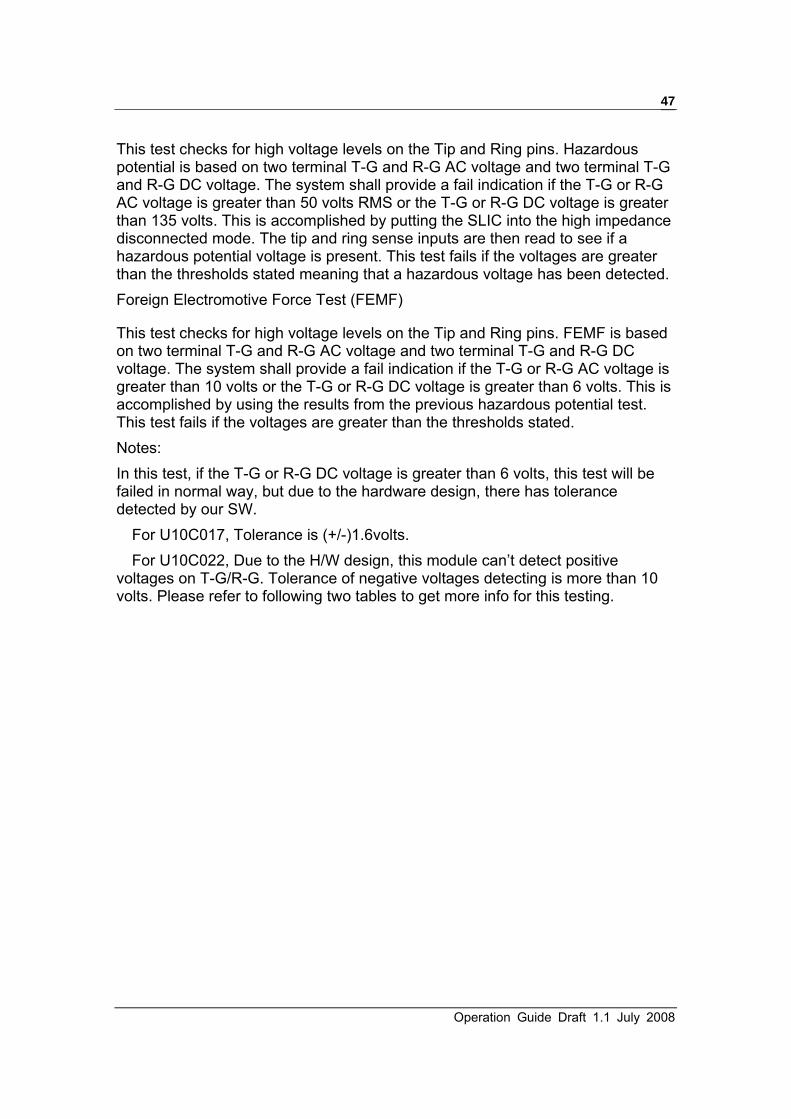
This test checks for high voltage levels on the Tip and Ring pins. Hazardous potential is based on two terminal T-G and R-G AC voltage and two terminal T-G and R-G DC voltage. The system shall provide a fail indication if the T-G or R-G AC voltage is greater than 50 volts RMS or the T-G or R-G DC voltage is greater than 135 volts. This is accomplished by putting the SLIC into the high impedance disconnected mode. The tip and ring sense inputs are then read to see if a hazardous potential voltage is present. This test fails if the voltages are greater than the thresholds stated meaning that a hazardous voltage has been detected. Foreign Electromotive Force Test (FEMF)
This test checks for high voltage levels on the Tip and Ring pins. FEMF is based on two terminal T-G and R-G AC voltage and two terminal T-G and R-G DC voltage. The system shall provide a fail indication if the T-G or R-G AC voltage is greater than 10 volts or the T-G or R-G DC voltage is greater than 6 volts. This is accomplished by using the results from the previous hazardous potential test. This test fails if the voltages are greater than the thresholds stated. Notes: In this test, if the T-G or R-G DC voltage is greater than 6 volts, this test will be failed in normal way, but due to the hardware design, there has tolerance detected by our SW.
For U10C017, Tolerance is (+/-)1.6volts. For U10C022, Due to the H/W design, this module can’t detect positive
voltages on T-G/R-G. Tolerance of negative voltages detecting is more than 10 volts. Please refer to following two tables to get more info for this testing.

U10C017/22/34 Telephony Version 1.1 July 2007
48
T-G R-G T-G R-G T-G R-G-10 -10 -11.634 -11.672 1.634 1.672 FAILE FAILE
-9.5 -9.5 -11.108 -11.23 1.608 1.73 FAILE FAILE
-9 -9 -10.608 -10.663 1.608 1.663 FAILE FAILE
-8.5 -8.5 -10.094 -10.211 1.594 1.711 FAILE FAILE
-8 -8 -9.651 -9.705 1.651 1.705 FAILE FAILE
-7.5 -7.5 -9.151 -9.177 1.651 1.677 FAILE FAILE
-7 -7 -8.652 -8.695 1.652 1.695 FAILE FAILE
-6.5 -6.5 -8.163 -8.202 1.663 1.702 FAILE FAILE
-6 -6 -7.652 -7.669 1.652 1.669 FAILE FAILE
-5.5 -5.5 -7.166 -7.172 1.666 1.672 PASS FAILE
-5 -5 -6.593 -6.701 1.593 1.701 PASS FAILE
-4.5 -4.5 -6.135 -6.188 1.635 1.688 PASS FAILE
-4 -4 -5.639 -5.659 1.639 1.659 PASS PASS
-3.5 -3.5 -5.135 -5.156 1.635 1.656 PASS PASS
-3 -3 -4.643 -4.632 1.643 1.632 PASS PASS
3 3 1.334 1.39 1.666 1.61 PASS PASS
3.5 3.5 1.815 1.871 1.685 1.629 PASS PASS
4 4 2.391 2.415 1.609 1.585 PASS PASS
4.5 4.5 2.851 2.876 1.649 1.624 PASS PASS
5 5 3.4 3.415 1.6 1.585 PASS PASS
5.5 5.5 3.89 3.915 1.61 1.585 PASS PASS
6 6 4.048 4.405 1.952 1.595 FAILE PASS
6.5 6.5 4.88 4.94 1.62 1.56 FAILE PASS
7 7 5.344 5.352 1.656 1.648 FAILE PASS
7.5 7.5 5.886 5.899 1.614 1.601 FAILE PASS
8 8 6.393 6.46 1.607 1.54 FAILE FAILE
8.5 8.5 6.808 6.936 1.692 1.564 FAILE FAILE
9 9 7.38 7.423 1.62 1.577 FAILE FAILE
9.5 9.5 7.875 7.875 1.625 1.625 FAILE FAILE
10 10 8.328 8.391 1.672 1.609 FAILE FAILE
U10C017 GR-909 FEMF TESTActuallyResult
DC Source Attached to SW Detected Voltages on Tolerance ExpectedReslut

Operation Guide Draft 1.1 July 2008
49
T-G R-G T-G R-G T-G R-G-12 -12 10.277 10.866 -22.277 -22.866 FAILE FAILE
-11.5 -11.5 10.277 10.227 -21.777 -21.727 FAILE FAILE
-11 -11 9.588 9.588 -20.588 -20.588 FAILE FAILE
-10.5 -10.5 8.948 8.948 -19.448 -19.448 FAILE FAILE
-10 -10 8.318 8.948 -18.318 -18.948 FAILE FAILE
-9.5 -9.5 8.309 8.309 -17.809 -17.809 FAILE FAILE
-9 -9 7.67 7.67 -16.67 -16.67 FAILE FAILE
-8.5 -8.5 7.031 7.031 -15.531 -15.531 FAILE FAILE
-8 -8 6.392 6.944 -14.392 -14.944 FAILE FAILE
-7.5 -7.5 6.392 6.392 -13.892 -13.892 FAILE FAILE
-7 -7 5.752 5.752 -12.752 -12.752 PASS FAILE
-6.5 -6.5 5.113 5.113 -11.613 -11.613 PASS FAILE
-6 -6 4.474 4.474 -10.474 -10.474 PASS FAILE
-5.5 -5.5 3.835 3.838 -9.335 -9.338 PASS PASS
-5 -5 3.835 3.835 -8.835 -8.835 PASS PASS
-4.5 -4.5 3.196 3.196 -7.696 -7.696 PASS PASS
-4 -4 2.556 2.556 -6.556 -6.556 PASS PASS
4 4 0 0 4 4 PASS PASS
4.5 4.5 0 0 4.5 4.5 PASS PASS
5 5 0 0 5 5 PASS PASS
5.5 5.5 0 0 5.5 5.5 PASS PASS
6 6 0 0 6 6 PASS FAILE
6.5 6.5 0 0 6.5 6.5 PASS FAILE
7 7 0 0 7 7 PASS FAILE
7.5 7.5 0 0 7.5 7.5 PASS FAILE
8 8 0 0 8 8 PASS FAILE
8.5 8.5 0 0 8.5 8.5 PASS FAILE
9 9 0 0 9 9 PASS FAILE
9.5 9.5 0 0 9.5 9.5 PASS FAILE
10 10 0 0 10 10 PASS FAILE
U10C022 GR-909 FEMF TESTActuallyResult
DC Source Attached to SW Detected Voltages on Tolerance ExpectedReslut
Receiver Off hook Test (ROH)
This test determines if the telephone receiver is in the off hook state. A receiver off hook is identified by sequentially generating two AC voltages across Tip and Ring, one at approximately 10 Vrms and one at approximately 5 Vrms. The tip and ring voltages are measured at each voltage setting to look for a non-linear relationship. If the second set of voltage readings is less than 85% of the
U10C017/22/34 Telephony Version 1.1 July 2007
50
intended value the test fails. This test differentiates between an off hook condition and a simple resistive fault. Tip to Ring Resistive Faults Test
This test checks for resistive faults which are DC resistance faults across Tip and Ring. The test provides a fail indication if the measured resistance is less than 150 K Ohms. Tip to Ground Resistive Faults Test
This test checks for resistive faults which are DC resistance faults across Tip and Ground. The test provides a fail indication if the measured resistance is less than 150 K Ohms. Ring to Ground Resistive Faults Test
This test checks for resistive faults which are DC resistance faults across Ring and Ground. The test provides a fail indication if the measured resistance is less than 150 K Ohms. Ringers Test
This test determines the presence of appropriate ringer terminations on the customer line. The test provides a fail indication when the equivalent ringer load across tip and ring is less than 0.175 REN or greater than 5 REN. During this test a low voltage AC signal is applied to the line. The voltage and current across the load are measured as the AC signal is applied. The ringing voltage is below the required level to activate a ring so audible ringing will not occur. The measured AC resistance is linearly proportional to the load on the endpoint in question and is converted to REN units. If this value is below 0.175 REN or above 5 REN the test fails. If not, this test passes. Off hook Simulation Test
This test simulates an off hook condition by utilizing an external relay. The test provides a pass indication if the following sequence of events occurs successfully. First, the MTA causes the external relay to simulate an off hook condition. Second, the MTA detects the off hook condition and sends a NTFY event to the CMS. Third the CMS acknowledges this NTFY and sends an RQNT to play dial tone. If all of these conditions occur within two second the test passes. After the test is completed the relay is disabled and the off hook condition ceases regardless of whether the test was successful or not. Note: this test will not pass unless a CMS is active that will request dial tone upon receiving a notification of off hook from the MTA. Self Check Test
This test verifies that several of the voice support modules of the MTA are operating correctly. In particular this test uses a variety of methods to verify that
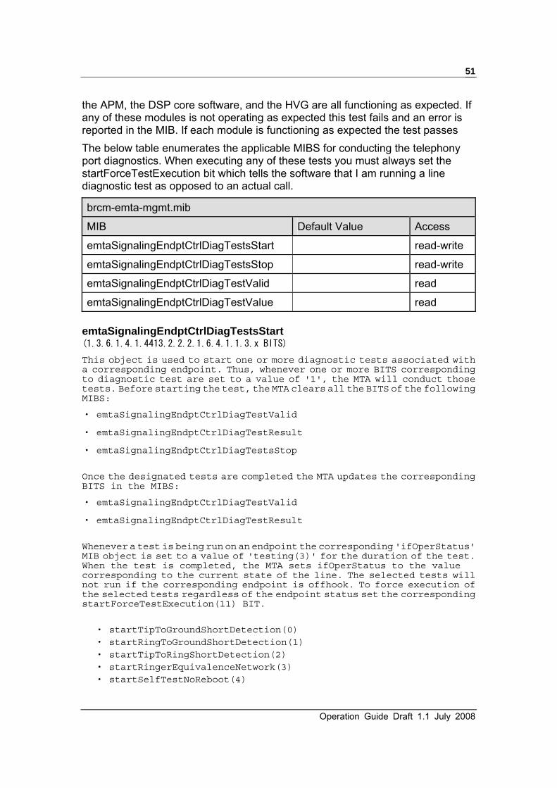
Operation Guide Draft 1.1 July 2008
51
the APM, the DSP core software, and the HVG are all functioning as expected. If any of these modules is not operating as expected this test fails and an error is reported in the MIB. If each module is functioning as expected the test passes The below table enumerates the applicable MIBS for conducting the telephony port diagnostics. When executing any of these tests you must always set the startForceTestExecution bit which tells the software that I am running a line diagnostic test as opposed to an actual call.
brcm-emta-mgmt.mib
MIB Default Value Access
emtaSignalingEndptCtrlDiagTestsStart read-write
emtaSignalingEndptCtrlDiagTestsStop read-write
emtaSignalingEndptCtrlDiagTestValid read
emtaSignalingEndptCtrlDiagTestValue read emtaSignalingEndptCtrlDiagTestsStart (1.3.6.1.4.1.4413.2.2.2.1.6.4.1.1.3.x BITS) This object is used to start one or more diagnostic tests associated with a corresponding endpoint. Thus, whenever one or more BITS corresponding to diagnostic test are set to a value of '1', the MTA will conduct those tests. Before starting the test, the MTA clears all the BITS of the following MIBS:
‧ emtaSignalingEndptCtrlDiagTestValid
‧ emtaSignalingEndptCtrlDiagTestResult
‧ emtaSignalingEndptCtrlDiagTestsStop
Once the designated tests are completed the MTA updates the corresponding BITS in the MIBS:
‧ emtaSignalingEndptCtrlDiagTestValid
‧ emtaSignalingEndptCtrlDiagTestResult
Whenever a test is being run on an endpoint the corresponding 'ifOperStatus' MIB object is set to a value of 'testing(3)' for the duration of the test. When the test is completed, the MTA sets ifOperStatus to the value corresponding to the current state of the line. The selected tests will not run if the corresponding endpoint is offhook. To force execution of the selected tests regardless of the endpoint status set the corresponding startForceTestExecution(11) BIT.
‧ startTipToGroundShortDetection(0) ‧ startRingToGroundShortDetection(1) ‧ startTipToRingShortDetection(2) ‧ startRingerEquivalenceNetwork(3) ‧ startSelfTestNoReboot(4)

U10C017/22/34 Telephony Version 1.1 July 2007
52
‧ startOffHookSimulationTest(5) ‧ startTip1ToRing2Short(6), -- Not currently implemented ‧ startTip2ToRing1Short(7), -- Not currently implemented ‧ startHazardousPotentialsTest(8), ‧ startstartForeignElectromotiveForceTest(9), ‧ startReceiverOffhook(10), ‧ startForceTestExecution(11)
emtaSignalingEndptCtrlDiagTestsStop (1.3.6.1.4.1.4413.2.2.2.1.6.4.1.1.4.x BITS) This object is used to stop the test corresponding to the bit being set if the test is not complete yet by the time when the bit is set.
‧ stopTipToGroundShortDetection(0), ‧ stopRingToGroundShortDetection(1), ‧ stopTipToRingShortDetection(2), ‧ stopRingerEquivalenceNetwork(3), ‧ stopSelfTestNoReboot(4), ‧ stopOffHookSimulationTest(5),
‧ stopTip1ToRing2Short(6), -- Not currently implemented ‧ stopTip2ToRing1Short(7), -- Not currently implemented ‧ stopHazardousPotentialsTest(8), ‧ stopForeignElectromotiveForceTest(9), ‧ stopReceiverOffhook(10)
emtaSignalingEndptCtrlDiagTestValid (1.3.6.1.4.1.4413.2.2.2.1.6.4.1.1.5.x BITS) This object indicates the validity of the corresponding test case that was initiated in the emtaSignalingEndptCtrlDiagTestsStart MIB. The corresponding bit will be set if the test was able to run and the test result is valid. Clear the corresponding bit if the MTA was not able to run the test or the test was not initiated or the test was not complete for any reason and hence, the result is invalid.
emtaSignalingEndptCtrlDiagTestResult(1.3.6.1.4.1.4413.2.2.2.1.6.4.1.1.6.x BITS)
This object indicates the result of the corresponding test that was initiated using emtaSignalingEndptCtrlDiagTestsStart MIB. If the corresponding completed successfully the bit will be set and if the test failed the bit will be cleared or 0.
‧ stopTipToGroundShortDetection(0), ‧ stopRingToGroundShortDetection(1), ‧ stopTipToRingShortDetection(2), ‧ stopRingerEquivalenceNetwork(3), ‧ stopSelfTestNoReboot(4), ‧ stopOffHookSimulationTest(5),
‧ stopTip1ToRing2Short(6), -- Not currently implemented
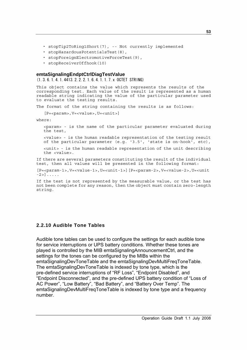
Operation Guide Draft 1.1 July 2008
53
‧ stopTip2ToRing1Short(7), -- Not currently implemented ‧ stopHazardousPotentialsTest(8), ‧ stopForeignElectromotiveForceTest(9), ‧ stopReceiverOffhook(10)
emtaSignalingEndptCtrlDiagTestValue (1.3.6.1.4.1.4413.2.2.2.1.6.4.1.1.7.x OCTET STRING) This object contains the value which represents the results of the corresponding test. Each value of the result is represented as a human readable string indicating the value of the particular parameter used to evaluate the testing results.
The format of the string containing the results is as follows:
[P=<param>,V=<value>,U=<unit>]
where:
<param> - is the name of the particular parameter evaluated during the test,
<value> - is the human readable representation of the testing result of the particular parameter (e.g. '3.5', 'state is on-hook', etc),
<unit> - is the human readable representation of the unit describing the <value>.
If there are several parameters constituting the result of the individual test, then all values will be presented in the following format:
[P=<param-1>,V=<value-1>,U=<unit-1>][P=<param-2>,V=<value-2>,U=<unit-2>].....
If the test is not represented by the measurable value, or the test has not been complete for any reason, then the object must contain zero-length string.
2.2.10 Audible Tone Tables Audible tone tables can be used to configure the settings for each audible tone for service interruptions or UPS battery conditions. Whether these tones are played is controlled by the MIB emtaSignalingAnnouncementCtrl, and the settings for the tones can be configured by the MIBs within the emtaSignalingDevToneTable and the emtaSignalingDevMultiFreqToneTable. The emtaSignalingDevToneTable is indexed by tone type, which is the pre-defined service interruptions of “RF Loss”, “Endpoint Disabled”, and “Endpoint Disconnected”, and the pre-defined UPS battery condition of “Loss of AC Power”, “Low Battery”, “Bad Battery”, and “Battery Over Temp”. The emtaSignalingDevMultiFreqToneTable is indexed by tone type and a frequency number.

U10C017/22/34 Telephony Version 1.1 July 2007
54
brcm-emta-mgmt.mib
MIB Default Value Access
emtaSignalingAnnouncementCtrl BITS (000) read-write
emtaSignalingDevToneWholeToneRepeatCount - read
emtaSignalingDevToneSteady - read
emtaSignalingDevToneFirstFreqValue - read
emtaSignalingDevToneSecondFreqValue - read
emtaSignalingDevToneDbLevel - read
emtaSignalingDevToneFreqOnDuration - read
emtaSignalingDevToneOffDuration - read
emtaSignalingDevToneFreqRepeatCount - read emtaSignalingAnnouncementCtrl (1.3.6.1.4.1.4413.2.2.2.1.6.4.2.0 BITS) This object contains the value controlling the announcements being played by the MTA in case of service interruption or UPS battery condition. The service interruptions announcements are required to be played if the phone is off-hook.
If bit announcementOnRfLoss(0) is set, the MTA MUST play an Announcement on all endpoints upon the RF loss. Otherwise (the bit is cleared) - the MTA MUST NOT play the announcement.
If bit announcementOnEndptDisabled(1) is set, the MTA MUST play the announcement on the end-point which has been disabled by one of the PacketCable compliant means: ifOperStatus/ifAdmingStatus becomes down(2), or end-point is not assigned to the particular CMS, or 'pktcMtaDevEnabled' MIB object is set to false(2). Otherwise - the MTA MUST NOT play the announcement.
If bit announcementOnEndptDisconnected(2) is set, the MTA MUST play the announcement on the end-point which becomes NCS disconnected (pktcNcsEndPntStatusError is in disconnected(3) state). Otherwise - the MTA MUST NOT play the announcement.
The UPS battery condition announcements are required to be played if the phone is off-hook and before dial tone.
If bit announcementOnACLoss(3) is set, the MTA MUST play an audible tone announcement upon detecting the loss of AC Power. The announcements are required to be played if the phone is off-hook and before dial tone. Otherwise (the bit is cleared) - the MTA MUST NOT play the announcement.
If bit announcementOnLowBatt(4) is set, the MTA MUST play an audible tone announcement upon detecting the low battery condition. The announcements are required to be played if the phone is off-hook and before dial tone. Otherwise (the bit is cleared) - the MTA MUST NOT play the announcement.
If bit announcementOnBadBatt(5) is set, the MTA MUST play an audible tone announcement upon detecting the bad battery condition. The announcements are required to be played if the phone is off-hook and before dial tone. Otherwise (the bit is cleared) - the MTA MUST NOT play the announcement.

Operation Guide Draft 1.1 July 2008
55
If bit announcementOnBattOverTemp(6) is set, the MTA MUST play an audible tone announcement upon detecting the battery over temperature condition. The announcements are required to be played if the phone is off-hook and before dial tone. Otherwise (the bit is cleared) - the MTA MUST NOT play the announcement.
The default value of this object corresponds to the functionality compliant with the PacketCable requirements - all bits are cleared.
‧ announcementOnRfLoss(0)
‧ announcementOnEndptDisabled(1),
‧ announcementOnEndptDisconnected(2)
‧ announcementOnACLoss(3)
‧ announcementOnLowBatt(4)
‧ announcementOnBadBatt(5)
‧ announcementOnBattOverTemp(6)
emtaSignalingDevToneWholeToneRepeatCount (1.3.6.1.4.1.4413.2.2.2.1.6.4.24.1.2.x Unsigned32) This is the repeat count which signifies how many times to repeat the entire on-off cadence sequence. This object should only be changed by the configuration file.
emtaSignalingDevToneSteady(1.3.6.1.4.1.4413.2.2.2.1.6.4.24.1.3.x Integer32)
This is the steady tone. Device must play out the on-off cadence sequence for pktcSigDevToneWholeRepeatCount times and then apply the last tone forever. This object should only be changed by the configuration file.
emtaSignalingDevToneFirstFreqValue(1.3.6.1.4.1.4413.2.2.2.1.6.4.25.1.2.x Unsigned32)
This object represents the value of the first frequency of a tone type. This object should only be changed by the configuration file.
emtaSignalingDevToneSecondFreqValue
(1.3.6.1.4.1.4413.2.2.2.1.6.4.25.1.3.x Unsigned32)
This object represents the value of the second frequency of a tone type. This object should only be changed by the configuration file.
emtaSignalingDevToneDbLevel (1.3.6.1.4.1.4413.2.2.2.1.6.4.25.1.4.x Integer32) This object contains the decibel level for each analog signal (tone) that is locally generated (versus in band supervisory tones) and sourced to the a-b terminals (TE connection point). Each tone in itself may consist of multiple frequencies as defined by the MIB table ‘emtaSignalingDevMultiFreqToneTable’. This object should only be changed by the configuration file.

U10C017/22/34 Telephony Version 1.1 July 2007
56
emtaSignalingDevToneFreqOnDuration (1.3.6.1.4.1.4413.2.2.2.1.6.4.25.1.5.x Unsigned32) This object contains the duration for which the frequency reference corresponding to the tone type is turned on. This object should only be changed by the configuration file.
emtaSignalingDevToneFreqOffDuration (1.3.6.1.4.1.4413.2.2.2.1.6.4.25.1.6.x Unsigned32) This object contains the duration for which the frequency reference corresponding to the tone type is turned off. This object should only be changed by the configuration file.
emtaSignalingDevToneFreqRepeatCount (1.3.6.1.4.1.4413.2.2.2.1.6.4.25.1.7.x Unsigned32)
This object indicates the number of times to repeat the cadence cycle represented by the on/off durations (represented by emtaSignalingDevToneFreqOnDuration and emtaSignalingDevToneFreqOffDuration). This object should only be changed by the configuration file.
2.2.11 Sends Syslog Stored In Cache
mtaMgmtMib.mib
MIB Default Value Access
syslogEnable disable(3) read-write
syslogEnable (1.3.6.1.4.1.4684.36.1.1.3 Integer) The object allows user Enable/Disable syslog, Setting this object to enableClean(1) will Send all events which are stored in the memory to syslog server. All events will be cleared after all of them are sent to syslog server, while setting to enableNotClean(2) will send all events which are stored in the memory to syslog server. All events will NOT be cleared after all of them are sent to syslog server. and disable(3) means that all message will be stored in memory pool only. Note:enableClean(1) and enableNotClean(2) will be changed to disable(3) automatically after all messages are sent to syslog server. Currently, we will send following events to syslog server while setting this value to “1” or “2”. 1) HW/SW Version; 2) Provisioning State; 3) RTP Statistics;

Operation Guide Draft 1.1 July 2008
57
Which includes: packet send/received/lost/lost ratio. Note: More RTP Statistics will be send when terminating the call, please refer to chapter 2.2.12.4.
4) RTP/RTCP Information; Which includes: Average Jitter/Max. Jitter/Average Latency(Delay). Note: More RTP/RTCP Information will be send when terminating the call, please refer to chapter 2.2.12.4.
5) MGCP Information; Which includes: Average Latency(Delay).
6) Counter of no Ack receive from CA; 7) Time Captured in Quarantine State;
8) Last Call Measurements;
Which includes: last call start/end time.
9) NCS Recv./Send;
2.2.12 New eMTA Trouble Shootings
2.2.12.1 RTP Status
mtaRtpStatus.mib
MIB Default Value Access
rtpTotalPacketSent - read-only
rtpTotalPacketReceived - read-only
rtpTotalPacketLost - read-only
rtpTotalPacketLostRatio - read-only
rtpTable - table-item
rtpStatusEntry - table-item
telPortNumber - table-item
rtpPacketSent - read-only
rtpPacketReceived - read-only
rtpPacketLossPrecentage - read-only
rtpAverageLatency - read-only
rtpAverageJitter - read-only
rtpMaximumJitter - read-only rtpTotalPacketSent
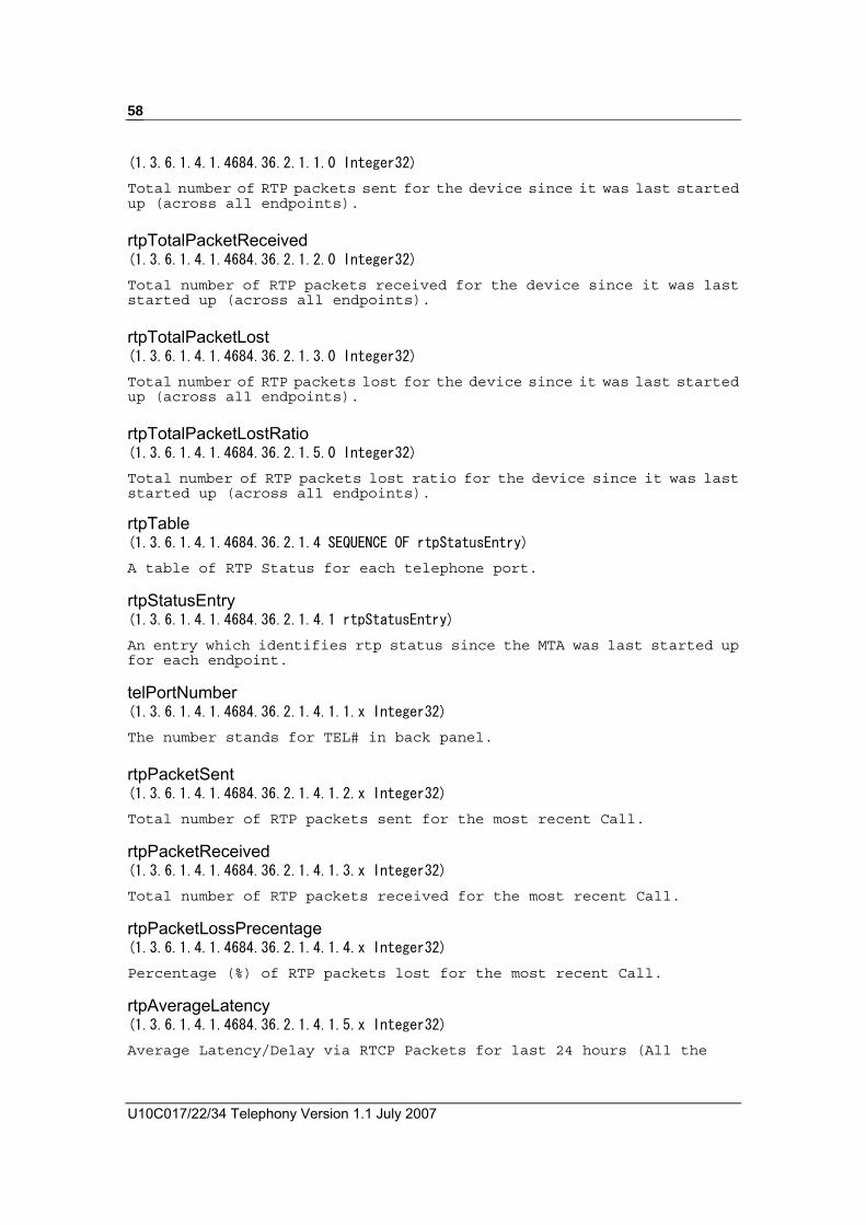
U10C017/22/34 Telephony Version 1.1 July 2007
58
(1.3.6.1.4.1.4684.36.2.1.1.0 Integer32) Total number of RTP packets sent for the device since it was last started up (across all endpoints). rtpTotalPacketReceived (1.3.6.1.4.1.4684.36.2.1.2.0 Integer32) Total number of RTP packets received for the device since it was last started up (across all endpoints). rtpTotalPacketLost (1.3.6.1.4.1.4684.36.2.1.3.0 Integer32) Total number of RTP packets lost for the device since it was last started up (across all endpoints). rtpTotalPacketLostRatio (1.3.6.1.4.1.4684.36.2.1.5.0 Integer32) Total number of RTP packets lost ratio for the device since it was last started up (across all endpoints).
rtpTable (1.3.6.1.4.1.4684.36.2.1.4 SEQUENCE OF rtpStatusEntry) A table of RTP Status for each telephone port. rtpStatusEntry (1.3.6.1.4.1.4684.36.2.1.4.1 rtpStatusEntry) An entry which identifies rtp status since the MTA was last started up for each endpoint. telPortNumber (1.3.6.1.4.1.4684.36.2.1.4.1.1.x Integer32) The number stands for TEL# in back panel. rtpPacketSent (1.3.6.1.4.1.4684.36.2.1.4.1.2.x Integer32) Total number of RTP packets sent for the most recent Call. rtpPacketReceived (1.3.6.1.4.1.4684.36.2.1.4.1.3.x Integer32) Total number of RTP packets received for the most recent Call. rtpPacketLossPrecentage (1.3.6.1.4.1.4684.36.2.1.4.1.4.x Integer32) Percentage (%) of RTP packets lost for the most recent Call. rtpAverageLatency (1.3.6.1.4.1.4684.36.2.1.4.1.5.x Integer32) Average Latency/Delay via RTCP Packets for last 24 hours (All the

Operation Guide Draft 1.1 July 2008
59
measurements must be in milliseconds). rtpAverageJitter (1.3.6.1.4.1.4684.36.2.1.4.1.6.x Integer32)
Average Jitter Measurements for last 24 hours.
rtpMaximumJitter (1.3.6.1.4.1.4684.36.2.1.4.1.7.x Integer32)
Maximun Jitter Measurements for last 24 hours. Note: these information will be send to syslog server if we set syslogEnable to “1” or “2”, for more information, please refer to 2.2.11.
2.2.12.2 MGCP Status
mtaMgcpStatus.mib
MIB Default Value Access
mgcpStatusTable - table-item
mgcpStatusEntry table-item
telPortNumber table-item
mgcpSuccessfulPacketSent - read-only
mgcpSuccessfulPacketReceived - read-only
mgcpNegativePacketSent - read-only
mgcpNegativePacketReceived - read-only
mgcpNoAckCount - read-only
mgcpLastPacketSent - read-only
mgcpLastPacketReceived - read-only
mgcpSignalingLatency - read-only
mgcpNoRSIPForceAckCount - read-only
mgcpNoRSIPDisconAckCount - read-only
mgcpNoRSIPRestartAckCount - read-only
mgcpQuarantineState - read-only
mgcpQuarantineCount read-only
mgcpClearQuarCounters read-write
mgcpClearNoAckCountersf read-write mgcpStatusTable

U10C017/22/34 Telephony Version 1.1 July 2007
60
(1.3.6.1.4.1.4684.36.2.2.1 SEQUENCE OF mgcpStatusEntry)
MGCP Status for each telphone port mgcpStatusEntry (1.3.6.1.4.1.4684.36.2.2.1.1 mgcpStatusEntry)
An entry which identifies MGCP status for telephone port. telPortNumber (1.3.6.1.4.1.4684.36.2.2.1.1.1.x Integer32)
The number stands for TEL# in back panel. mgcpSuccessfulPacketSent (1.3.6.1.4.1.4684.36.2.2.1.1.2.x Integer32)
Count of successful messages transmitted to Call Agent for last 24 hours. mgcpSuccessfulPacketReceived (1.3.6.1.4.1.4684.36.2.2.1.1.3.x Integer32)
Count of successful messages received from Call Agent for last 24 hours. mgcpNegativePacketSent (1.3.6.1.4.1.4684.36.2.2.1.1.4.x Integer32)
Count of negative acknowledgements sent to Call Agent for last 24 hours. mgcpNegativePacketReceived (1.3.6.1.4.1.4684.36.2.2.1.1.5.x Integer32)
Count of negative acknowledgements received from Call Agent for last 24 hours. mgcpNoAckCount (1.3.6.1.4.1.4684.36.2.2.1.1.6.x Integer32)
Count of No Acknowledgements received from the Call Agent for the notifies sent for last 24 hours. mgcpLastPacketSent (1.3.6.1.4.1.4684.36.2.2.1.1.7.x OCTET STRING)
Last NCS message sent to Call Agent. mgcpLastPacketReceived (1.3.6.1.4.1.4684.36.2.2.1.1.8.x OCTET STRING)
Last NCS message received from Call Agent. mgcpSignalingLatency (1.3.6.1.4.1.4684.36.2.2.1.1.9.x Integer32)
Average Latency/Delay for Response to MGCP Messages for last 24 hours (All the measurements must be in milliseconds). mgcpNoRSIPForceAckCount (1.3.6.1.4.1.4684.36.2.2.1.1.10.x Unsigned32)

Operation Guide Draft 1.1 July 2008
61
This object contains the number of times no MGCP response was received from the Call Agent for a sent RSIP with forced since reboot. mgcpNoRSIPDisconAckCount (1.3.6.1.4.1.4684.36.2.2.1.1.11.x Unsigned32)
This object contains the number of times no MGCP response was received from the Call Agent for a sent RSIP with disconnected since reboot. mgcpNoRSIPRestartAckCount (1.3.6.1.4.1.4684.36.2.2.1.1.12.x Unsigned32)
This object contains the number of times no MGCP response was received from the Call Agent for a sent RSIP with restart since reboot. mgcpNoNTFYAckCount (1.3.6.1.4.1.4684.36.2.2.1.1.13.x Unsigned32)
This object contains the number of times no MGCP response was received from the Call Agent for a sent NTFY since reboot. mgcpQuarantineState (1.3.6.1.4.1.4684.36.2.2.1.1.14.x TruthValue)
This object reflect the 'quarantine state' of a MTA endpoint. The True indicates that the endpoint is in quarantine. The "quarantine" state is defined by the standard PacketCable MIB pktcEnNcsEndPntQuarantineState(1.3.6.1.4.1.4491.2.2.6.2.1.2.1.1.1.x Integer32). We are considered to be in the quarantine state when this MIB is set to either lockstep or extended lockstep. mgcpQuarantineCount (1.3.6.1.4.1.4684.36.2.2.1.1.15.x Unsigned32)
This object contains the total number of events that occur when the endpoint is in quarantine. mgcpClearQuarCounters (1.3.6.1.4.1.4684.36.2.2.1.1.16.x TruthValue)
Allows user to clear quarantine counter(mgcpQuarantineCount). mgcpClearNoAckCounters (1.3.6.1.4.1.4684.36.2.2.1.1.17.x TruthValue)
Allows user to clear no acknowledgement counters(mgcpNoRSIPForceAckCount, mgcpNoRSIPDisconAckCount, mgcpNoRSIPRestartAckCount and mgcpNoNTFYAckCount).
2.2.12.3 Telephone Port Status
mtaTelephonePortStatus.mib
MIB Default Value Access

U10C017/22/34 Telephony Version 1.1 July 2007
62
telPortStatusTable - table-item
telPortStatusEntry - table-item
telPortNumber - table-item
operation - read-only
hook - read-only m
slic - read-only
linePower - read-only
lastCallStartTime - read-only
lastCallEndTime - read-only telPortStatusTable (1.3.6.1.4.1.4684.36.1.3 SEQUENCE OF telPortStatusEntry)
Table of status for each telephone port telPortStatusEntry (1.3.6.1.4.1.4684.36.1.3.1 telPortStatusEntry)
An entry which identifies telephone port information for each telephone port. telPortNumber (1.3.6.1.4.1.4684.36.1.3.1.1.x Integer32)
The number stands for TEL# in back panel. operation (1.3.6.1.4.1.4684.36.1.3.1.2.x Integer32)
Current Operational status of the endpoint, return 1 means this endpoint is up, 2 means it is down, while 3 means “shutDownInProgress”. hook (1.3.6.1.4.1.4684.36.1.3.1.3.x Integer32) Endpoint status, returns 1 means ON-HOOK, 2 means OFF-HOOK, while returns 3 means DISCONNECTED. slic (1.3.6.1.4.1.4684.36.1.3.1.4.x Integer32)
SLIC status for the line regarding over Temperature condition, returns 1 means “normal”, returns 2 means “abnormal”, while returns 3 means “unsupported”. linePower (1.3.6.1.4.1.4684.36.1.3.1.5.x TruthValue)
Return value of this object indicates whether the corresponding endpoint’s power is one or off. Returns true(1) means that the line power is on while returning fasle(2) means line power is off.

Operation Guide Draft 1.1 July 2008
63
lastCallStartTime (1.3.6.1.4.1.4684.36.1.3.1.6.x OCTET STRING)
Start-of-Call Time Stamp - The timestamp indicating the beginning of the last call made from the eMTA lastCallEndTime (1.3.6.1.4.1.4684.36.1.3.1.7.x OCTET STRING)
End-of-Call Time Stamp - The timestamp indicating the end of the last call made from the eMTA
2.2.12.4 Per Call Measurements
Following MIBs are used to get call statistics for every phone call, one entry will be automatically created in basicStatisticsTable and rtcpXrMetricsTable after the call was terminated. For packetLogTable, one entry will be created after your on-hook the phone but not terminated the call. The max. entry created by MTA was defined in “maxNumOfCallStored”. Call statistics in basicStatisticsTable and rtcpXrMetricsTable will send to syslog server when every call was terminated. You call also get those statistics via Telnet CLI. mtaPerCallMeasurements.mib
MIB Default Value Access
maxNumOfCallStored 10 read-write
basicStatisticsTable - table-item
basicStatisticsEntry - table-item
basicStatisticsIndex - table-item
endptID - read-only
numOfPktsSent - read-only
numOfOctsSent - read-only
numOfPktsRecv - read-only
numOfOctsRecv - read-only
numOfPktsLost - read-only
intervalJitter - read-only
averageTransmissionDelay - read-only
destEndptIpaddr - read-only

U10C017/22/34 Telephony Version 1.1 July 2007
64
rfSignalToNosieLevel - read-only
rfTxLevel - read-only
rfRxLevel - read-only
rtcpXrMetricsTable - table-item
rtcpXrMetricsEntry - table-item
rtcpXrMetricsIndex - table-item
rtcpXrEndptId read-only
mosScores read-only
residualEchoReturnLoss read-only
jbDiscardRate read-only
jbAdjustmentRate read-only
jbMaxSize read-only
signalLevels read-only
noiseLevels read-only
networkRoundTripDelay read-only
packetLogTable table-item
packetLogEntry table-item
packetLogIndex table-item
packetLogPerCall read-only maxNumOfCallStored (1.3.6.1.4.1.4684.36.1.7.1.0 Integer32)
The max number of calls for which the eMTA stores statistics, and the range is 2 to 20, the default value is 10. basicStatisticsTable (1.3.6.1.4.1.4684.36.1.7.2 SEQUENCE OF basicStatisticsEntry)
Table of RTP statistics for each call basicStatisticsEntry (1.3.6.1.4.1.4684.36.1.7.2.1 basicStatisticsEntry)
An entry which identifies RTP statistics for each call. basicStatisticsIndex (1.3.6.1.4.1.4684.36.1.7.2.1.1.x Integer32)
The call index, the smallest value means the most recent call. endptID

Operation Guide Draft 1.1 July 2008
65
(1.3.6.1.4.1.4684.36.1.7.2.1.2.x Integer32)
Endpoint ID for each call. numOfPktsSent (1.3.6.1.4.1.4684.36.1.7.2.1.3.x Integer32)
Number of Packets Sent - The total number of packets transmitted by the sender since starting transmission on the connection. numOfOctsSent (1.3.6.1.4.1.4684.36.1.7.2.1.4.x Integer32)
Number of Octets Sent - The total number of payload octets transmitted in RTP packets by the sender since starting transmission on the connection numOfPktsRecv (1.3.6.1.4.1.4684.36.1.7.2.1.5.x Integer32)
Number of Packets Received - The total number of packets received by the sender since starting transmission on the connection. numOfOctsRecv (1.3.6.1.4.1.4684.36.1.7.2.1.6.x Integer32)
Number of Octets Received - The total number of payload octets received in RTP packets by the sender since starting transmission on the connection. numOfPktsLost (1.3.6.1.4.1.4684.36.1.7.2.1.7.x Integer32)
Number of Packets Lost - The total number of RTP data packets that have been lost since the beginning of reception. This number is defined as the number of packets less the number of packets actually received, where the number of packets received includes any which are late or duplicates. intervalJitter (1.3.6.1.4.1.4684.36.1.7.2.1.8.x Integer32)
Interval Jitter - An estimate of the statistical variance of the RTP data packet inter-arrival time, measured in milliseconds and expressed as an unsigned integer averageTransmissionDelay (1.3.6.1.4.1.4684.36.1.7.2.1.9.x Integer32)
Average Transmission Delay - For each call originating and terminating call ,an estimate of the network latency, expressed in milliseconds. This is the average value of the difference between the NTP timestamp indicated by the senders of the RTPC messages and the NTP timestamp of the receivers, measured when the messages are received. destEndptIpaddr (1.3.6.1.4.1.4684.36.1.7.2.1.10.x OCTET STRING)
Reports the IP address for the terminating end point of each call originated from the eMTA. rfSignalToNosieLevel

U10C017/22/34 Telephony Version 1.1 July 2007
66
(1.3.6.1.4.1.4684.36.1.7.2.1.11.x Integer32)
RF Signal to Noise Levels - For each originating and terminating call, a general measurement of the ratio of signal power to noise power. rfTxLevel (1.3.6.1.4.1.4684.36.1.7.2.1.12.x Integer32)
RF Tx Level - For each originating and terminating call, the RF transmit level, measured in dB, as defined in the DOCSIS specifications. rfRxLevel (1.3.6.1.4.1.4684.36.1.7.2.1.10.x Integer32)
RF Rx Level - For each originating and terminating call, the RF receive level, measured in dB, as defined in the DOCSIS specifications. rtcpXrMetricsTable (1.3.6.1.4.1.4684.36.1.7.3 SEQUENCE OF rtcpXrMetricsEntry)
Table of RTCP-XR Metrics for each call. rtcpXrMetricsEntry (1.3.6.1.4.1.4684.36.1.7.3.1 rtcpXrMetricsEntry)
An entry which identifies RTCP-XR Metrics for each call. rtcpXrMetricsIndex (1.3.6.1.4.1.4684.36.1.7.3.1.1.x Integer32)
The call index, the smallest value means the most recent call rtcpXrEndptId (1.3.6.1.4.1.4684.36.1.7.3.1.2.x Integer32)
Endpoint ID for each call. mosScores (1.3.6.1.4.1.4684.36.1.7.3.1.3.x DisplayString)
MOS scores - For each call originating and terminating call, the eMTA would provide a numerical indication of the perceived quality of received media after compression and/or transmission. The MOS MUST be expressed as a single number in the range of 1.0 to 5.0. The associated quality characteristics are defined for each score in the table below (per ITU-T recommendation P.800). The eMTAs reporting of MOSs MUST correspond to the characteristics defined as below. 5 EXCELLENT Imperceptible 4 GOOD Perceptible, but not annoying 3 FAIR Slightly annoying 2 POOR Annoying 1 BAD Very annoying residualEchoReturnLoss (1.3.6.1.4.1.4684.36.1.7.3.1.4.x Integer32)
Residual Echo Return Loss - The residual echo return loss relates to the

Operation Guide Draft 1.1 July 2008
67
effective echo level that a user would hear. For each originating and terminating call, the eMTA would report the ratio between the transmitted signal level and the received echo level expressed in dB. The echo return loss after the effects of echo cancellation, in dB. No sign is necessary since valid values MUST be greater than or equal to 0 dB jbDiscardRate (1.3.6.1.4.1.4684.36.1.7.3.1.5.x Integer32)
Jitter Buffer Discard Rate - For each originating and terminating call, the number of packets discarded by the eMTA's jitter buffer. The proportion of the packets discarded by the receiving jitter buffer since the start oftransmission expressed as an 8-bit binary fraction obtained by dividing the number of packets discarded by the jitter buffer by the total number of packets expected by the receiver, multiplying this value by 256 and taking the integer portion of the result. jbAdjustmentRate (1.3.6.1.4.1.4684.36.1.7.3.1.6.x Integer32)
Jitter Buffer Adjustment Rate - For each originating and terminating call, the jitter buffer's adjustment rate, specified in milliseconds JB adjustment rate, as defined in RFC 3611 RTCP-XR, is calculated from the jitter buffer rate J, an approximate measure (in 0-15) of the aggressiveness of the adaptive jitter buffer. This information can be extracted from the RTCP-XR report. adjustment rate = 2 * J * frame size (ms) jbMaxSize (1.3.6.1.4.1.4684.36.1.7.3.1.7.x DisplayString)
Jitter Buffer Maximum Size - For each originating and terminating call, the maximum size of the jitter buffer, specified in milliseconds. JB maximum size is the maximum JB delay (JBM) as defined in RFC 3611 RTCP-XR. JB maximum size = JBM / (frame size) signalLevels (1.3.6.1.4.1.4684.36.1.7.3.1.8.x Integer32)
Signal Levels - For each originating and terminating call, the signal levels, measure in dB, as defined in the DOCSIS specifications. The ratio of the average signal level to a 0 dBm0 reference, expressed in dB. This is expressed as an integer with an optional negative '-' sign. When the sign is omitted, a positive value is assumed. Typical values should generally be between -15 and -20. noiseLevels, (1.3.6.1.4.1.4684.36.1.7.3.1.9.x Integer32)
Noise Levels - For each originating and terminating call, the noise levels, measured in dB, as defined in the DOCSIS specifications.
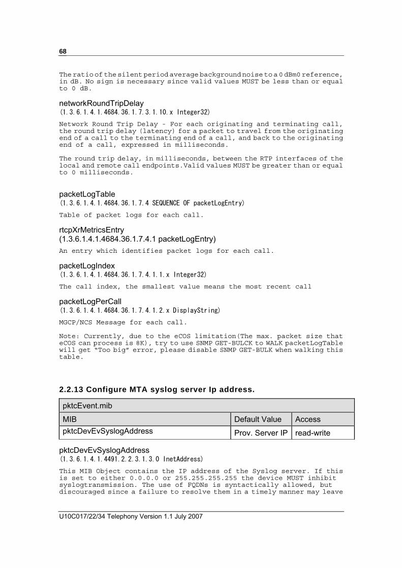
U10C017/22/34 Telephony Version 1.1 July 2007
68
The ratio of the silent period average background noise to a 0 dBm0 reference, in dB. No sign is necessary since valid values MUST be less than or equal to 0 dB. networkRoundTripDelay (1.3.6.1.4.1.4684.36.1.7.3.1.10.x Integer32)
Network Round Trip Delay - For each originating and terminating call, the round trip delay (latency) for a packet to travel from the originating end of a call to the terminating end of a call, and back to the originating end of a call, expressed in milliseconds. The round trip delay, in milliseconds, between the RTP interfaces of the local and remote call endpoints.Valid values MUST be greater than or equal to 0 milliseconds. packetLogTable (1.3.6.1.4.1.4684.36.1.7.4 SEQUENCE OF packetLogEntry)
Table of packet logs for each call. rtcpXrMetricsEntry (1.3.6.1.4.1.4684.36.1.7.4.1 packetLogEntry) An entry which identifies packet logs for each call. packetLogIndex (1.3.6.1.4.1.4684.36.1.7.4.1.1.x Integer32)
The call index, the smallest value means the most recent call packetLogPerCall (1.3.6.1.4.1.4684.36.1.7.4.1.2.x DisplayString)
MGCP/NCS Message for each call. Note: Currently, due to the eCOS limitation(The max. packet size that eCOS can process is 8K), try to use SNMP GET-BULCK to WALK packetLogTable will get “Too big” error, please disable SNMP GET-BULK when walking this table.
2.2.13 Configure MTA syslog server Ip address.
pktcEvent.mib
MIB Default Value Access pktcDevEvSyslogAddress Prov. Server IP read-write
pktcDevEvSyslogAddress (1.3.6.1.4.1.4491.2.2.3.1.3.0 InetAddress)
This MIB Object contains the IP address of the Syslog server. If this is set to either 0.0.0.0 or 255.255.255.255 the device MUST inhibit syslogtransmission. The use of FQDNs is syntactically allowed, but discouraged since a failure to resolve them in a timely manner may leave

Operation Guide Draft 1.1 July 2008
69
the device without access to the Syslog daemon during critical network events. The type of address this object represents is defined by the MIB Object pktDevEvSyslogAddressType. If an SNMP SET results in a type that does not match that indicated by the MIB Object pktcDevEvSyslogAddressType, the PacketCable device MUST reject the SNMP SET with an 'inconsistent value' error.
2.2.14 Configure Battery Low Threshold
ups_rfc1628.mib
MIB Default Value Access upsEstimatedMinutesRemaining - read-only upsEstimatedChargeRemaining - read-only upsConfigLowBattTime 30 read-write
upsEstimatedMinutesRemaining (1.3.6.1.2.1.33.1.2.3.0 Integer32)
An estimate of the time to battery charge depletion under the present load conditions if the utility power is off and remains off, or if it were to be lost and remain off. upsEstimatedChargeRemaining (1.3.6.1.2.1.33.1.2.4.0 Integer32)
An estimate of the battery charge remaining expressed as a percent of full charge. upsConfigLowBattTime (1.3.6.1.2.1.33.1.9.7.0 Integer32)
The value of upsEstimatedMinutesRemaining at which a lowBattery condition is declared, describes in minutes . For agents which support only discrete (discontinuous) values, then the agent shall round up to the next supported value. If the requested value is larger than the largest supported value, then the largest supported value shall be selected. Battery Low event will be brought up if the return value of upsEstimatedMinutesRemaining is less than this threshold.
2.2.15 Configure Call Waiting Caller ID(CWCID Parameters
mtaMgmtMib.mib
MIB Default Value Access CWCIDFollowGR30 false(2) read-write

U10C017/22/34 Telephony Version 1.1 July 2007
70
CasToneForCWCID 15dB read-write
FskToneForCWCID 15dB read-write
CWCIDFollowGR30 (1.3.6.1.4.1.4684.36.1.1.11.0 Integer32)
The object allows user to configure (toggle) the eMTA to use either the values defined
in Telcordia GR-30 or the customer-defined values.
If set this object’s value to false(2), CasToneForCWCID and FskToneForCWCID can be
configured, and the value of these two objects will be changed to customer defined
default value -15dB, setting CasToneForCWCID and FskToneForCWCID’s value will be
failed while setting its value to true(1). And the value of CAS tone and FSK tone will
follow GR-30 defined. CasToneForCWCID (1.3.6.1.4.1.4684.36.1.1.12.0 Integer32) Allows use to configure CAS tone. Note 1) Valid values allow to set: 10~20dB, with a step of 1dB. 2) Set/get this object’s value should be positive number, but actually
its represents negative number. 3) Try to set this object will be failed if currently value of
CWCIDFollowGR30 is true; FskToneForCWCID (1.3.6.1.4.1.4684.36.1.1.13.0 Integer32)
Allows use to configure FSK tone. Note 1) Valid values allow to set: 100~200, with a step of 10. 2) Set/get this object’s value should be positive number, but actually
its represents negative number and should be divided by 10. 3) Try to set this object will be failed if currently value of
CWCIDFollowGR30 is true;
2.2.16 Get MTA Device Information
mtaInformationMib.mib
MIB Default Value Access deviceIpAddress - read-only deviceRouterAddress - read-only deviceSubnetMask - read-only deviceDNSIpAddress - read-only deviceMtaDhcpOption - read-only

Operation Guide Draft 1.1 July 2008
71
deviceMtaFQDN - read-only deviceIpAddress (1.3.6.1.4.1.4684.36.1.2.1.0 IpAddress) This object allows you get MTA device IP. deviceRouterAddress (1.3.6.1.4.1.4684.36.1.2.2.0 IpAddress) This object allow you get router IP address of MTA device. deviceSubnetMask(1.3.6.1.4.1.4684.36.1.2.3.0 IpAddress) This object allows you get subnet mask of MTA device deviceDNSIpAddress (1.3.6.1.4.1.4684.36.1.2.4.0 IpAddress) This object allow you get DNS server IP address deviceMtaDhcpOption (1.3.6.1.4.1.4684.36.1.2.5.0 OCTET STRING) This object allows you get content of option 122 or 177 from DHCP server. deviceMtaFQDN (1.3.6.1.4.1.4684.36.1.2.7.0 OCTET STRING) This object allows you get MTA FQDN (= option 12 + option 15 are from DHCP)

U10C017/22/34 Telephony Version 1.1 July 2007
72
3 Ambit VSIFs
MTA supports standard DOCSIS VSIF (Vendor Specific Information Field) mechanism for DOCSIS and PacketCable configuration. There are two methods to use the VSIF configuration, one is put the VSIF data into DOCSIS configuration file TLV43, and another is use VSIF mib object in PacketCable configuration file. When use TLV43 in DOCSIS configure file, all VSIFs must be under the unique VendorID (00:D0:59) and they must be in DOCSIS configuration file. The Vendor ID is always 00:D0:59 and OUI of Mac address of MTA might be different from Vendor ID.

Operation Guide Draft 1.1 July 2008
73
3.1 RELATED MIBS TO AMIT VSIFS. When use VSIF mib in configuration file, use VSIFString(1.3.6.1.4.1.4684.36.1.5.1.0 OCTET STRING) to pass VSIF string to the eMTA, following is the sample of VSIF string, VSIF65=1; VSIF66=0; VSIF67=0; VSIF68=1; VSIF87=1; VSIF89=3 mtaMgmtMib.mib
MIB Default Value Access VSIFString - read-write
parseVSIFstate - read-only
currentConfig - read-only
VSIFString (1.3.6.1.4.1.4684.36.1.5.1.0 OCTET STRING) Setting VSIF values via SNMP, the format should be like this “VSIF64=1;VSIF66=0;VSIF70=0”. parseVSIFstate (1.3.6.1.4.1.4684.36.1.5.2.0 TruthValue) returns true if MTA parse VSIF successfully, while returning false indicates that there has errors of parsing VSIF. currentConfig (1.3.6.1.4.1.4684.36.1.5.3.0 OCTET STRING) Display current VSIF configuration.
3.2 DETAIL INFORMATION/EXPLANATIONS TO ALL VSIFS.
3.2.1 Telephony Root Certificate Configuration Type: 64 Length: 1 byte Value: 0: Auto Selection (Default) 1: PacketCable Telephony Root Certificate 2: PacketCable Test Telephony Root Certificate 3: IPFONIX Telephony Root Certificate 4: Manufacturer Telephony Root Certificate 5: MSO Telephony Root Certificate Description: EMTA can use different telephony root certificate to decode AS_RSP in secure provisioning flow. Operators can specify a telephony root certificate type in DOCSIS configuration file to select correct telephony root certificate for AS_RSP decoding. If operators did not specify the VSIF in DOCSIS configuration file, it starts at “Auto Selection” mode directly. Under this mode, MTA will

U10C017/22/34 Telephony Version 1.1 July 2007
74
use each certificate of the following list to decode AS_RSP. A. PacketCable Telephony Root Certificate B. PacketCable Test Telephony Root Certificate C. IPFONIX Telephony Root Certificate D. Manufacturer Telephony Root Certificate
If operator specifies value 5 (MSO Telephony Root Certificate) in DOCSIS configuration file, he/she has to use telnet command to download the certificate into modem.
3.2.2 DTMF Relay (RFC2833 Relay) Type: 65 Length: 1 (byte) Value: 0: CMS Start (Default) 1: GW Start Description: MTA supports DTMF Relay (RFC2833 Relay). There are two modes for starting DTMF relay. One is “CMS start” mode and another is “GW Start” mode. Under “CMS start” mode, MTA does not include RFC 2833 attributes in SDP unless it received “ftmp” in LCO. Under “GW start” mode, MTA always include RFC 2833 attributes in SDP and its RTP type are always 101.
3.2.3 PHS Enable Type: 66 Length: 1 byte Value: 0: Disable (Default) 1: Enable Description: MTA supports PHS for saving US/DS bandwidth for voice streams. Some CMTS do not support PHS mechanism or have wrong implementation. Operator can use the VSIF to enable or disable PHS.
3.2.4 PacketCable Primary DHCP Option Configuration Type: 67 Length: 1 byte Value: 0 or 122: Option 122 (Default) 1 or 177: Option 177 Description: MTA supports two DHCP options (122 and 177) for DOCSIS and PacketCable DHCP provisioning flow. Operators can use the VSIF to select correct DHCP option for provisioning. If user did not specify the VSIF, MTA will uses option 122 to be his DHCP option. If latest DHCP option in DOCSIS configuration file are different from pervious one, modem will restart its provisioning procedure again.

Operation Guide Draft 1.1 July 2008
75
3.2.5 CPE Counting Type: 68 Length: 1 byte Value: 0: Maximum number of CPEs (type: 18) should be applied to CPEs and MTA 1: Maximum number of CPEs (type: 18) should be applied to CPEs. (Default) Description: The Maximum number of CPEs (type: 18) is a standard and popular DOCSIS configuration setting in DOCSIS configuration file. If operators set this value to 1, it means that MTA does not occupy CPE table. If operators set this value to 0, it means that operator have to set Maximum number of CPEs to 2 to allow one CPE and MTA to goes online together.
3.2.6 DQOS Mode Type: 69 Length: 1 byte Value: 1: GW Start (Default) 2: CMS Start Description: MTA provides QoS service (DOCSIS service flow) for voice stream. There are two modes for starting QOS service flow voice stream. One is “GW Start” mode and another is “CMS Start” mode. GW start mode: MTA always creates QOS channels for voice stream. CMS start mode: MTA must receive “gate-id” from CMS and then it creates DOCSIS QOS channels for voice streams.
3.2.7 PowerSaving Interface Controller Type: 70 Length: 1 byte Value: 0(00000000b): Disable Ethernet and USB under battery mode. (Default) 1(00000001b): Enable Ethernet but USB under battery mode. 2(00000010b): Disable Ethernet but USB under battery mode. 3(00000011b): Enable Ethernet and USB under battery mode. Description: MTA can disable interfaces under battery mode for power saving. The VSIF can configure which interface should be disabled under battery mode. By default, all interfaces will be disabled under battery mode.

U10C017/22/34 Telephony Version 1.1 July 2007
76
3.2.8 Buffer size for upstream queue for voice stream Type: 71 Length: 1 byte Value: 3 ~ 16: Size of queue Description: MTA upstream queue size for voice stream can be configured. Its default size is 3. In normal case, the VSIF should be always 3.
3.2.9 Transmission Gain Configuration Type: 72 Length: 1 byte Value: -16 ~ +16: Gain value in dB in transmission direction. Description: MTA supports gain configuration in transmission direction. Transmission direction is from telephone to RF direction. Operator can use this VSIF to increase or decrease transmission gain by 1 dB step. Default is -6(0xFA) dB. When using this VSIF in DOCSIS VSIF tag, the value will represent as two’s complement, for example, if want to set the gain value to -3 dB, need to set the value 0xFD in VSIF Tag. When using this VSIF in mib object, the negative value was acceptable, for example, “VSIF72=-3” was acceptable in VSIF string mib.
3.2.10 Receiving Gain Configuration Type: 73 Length: 1 byte Value: -16 ~ +16: Gain value in dB in receiving direction. Description: MTA supports gain configuration in receiving direction. Receiving direction is from RF to telephone direction. Operator can use this VSIF to increase or decrease receiving gain by 1 dB step. Default is -6(0xFA) dB. When using this VSIF in DOCSIS VSIF tag, the value will represent as two’s complement, for example, if want to set the gain value to -3 dB, need to set the value 0xFD in VSIF Tag. When using this VSIF in mib object, the negative value was acceptable, for example, “VSIF72=-3” was acceptable in VSIF string mib. Default value: -6.
3.2.11 Software Download Configuration Type: 74 Length: 1 byte Value: 0: Disable DOCSIS software-download if any one of telephone port is under off hook. (Default)

Operation Guide Draft 1.1 July 2008
77
1: Always enable DOCSIS software-download Description: MTA always restarts itself after software was downloaded from TFTP server. The VSIF can be used to disable software-download under off hook status to avoid interrupt users communication.
3.2.12 CLI Interface Configuration Type: 75 Length: 1 byte Value: 0(00000000b): Disable Telnet and SSH 1(00000001b): Enable Telnet but SSH (Default) 2(00000010b): Disable Telnet but SSH 3(00000011b): Enable Telnet and SSH Description: MTA supports two kinds of CLIE, SSH and Telnet. The VISF can be used to configure enable/disable telnet and SSH.
3.2.13 SNMP Community for PacketCable SNMP Access Type: 76 Length: 256 bytes, Maximum Value: String of community Description: The VSIF can be used to configure community string (read/write) of PacketCable SNMP access under BASIC and Hybrid provisioning flow. If VSIF-81 is set to “1”, the VSIF will be disabled automatically. Community string should follow VSIF-81 configuration. Default value should be 'private'.
3.2.14 PacketCable Provisioning Mode Type: 77 Length: 1 byte Value: 0: Auto Mode (Default) 1: BASIC.1 2: BASIC.2 3: HYBRID.1 4: HYBRID.2 Description: MTA supports secure, basic and hybrid provisioning flows. The VSIF can be used to specify which provisioning flow should be used in PacketCable provisioning. If operator wants to enable “Auto Mode” provisioning, the VSIF-67 must be 0 or 122 (option-122 mode). If operator set VSIF-67 to 1 or 177 and set this VSIF-77 to 1, MTA always start secure provisioning flow. If

U10C017/22/34 Telephony Version 1.1 July 2007
78
operators wants to enable basic or hybrid provisioning, the VSIF-67 must be set to 1 or 177.
3.2.15 FQDN Verification Configuration Type: 78 Length: 1 byte Value: 0: Enable, Provisioning server, Kerbero-Realm and CMS name must be in FQDN format. (Default) 1: Disable, Provisioning server, Kerbero-Realm and CMS name can be in IPv4 format. Description: MTA supports two kinds format, FQDN and IPv4, for Provisioning server, Kerbero-Realm and CMS. If one of them are not FQDN format, the VSIF must be set to 1 to have a successful provisioning.
3.2.16 PacketCable Configuration File Verification Configuration Type: 79 Length: 1 byte Value: 0: Enable, PacketCable configuration file must includes all necessary items that are defined in PacketCabloe 1.0/1.5 provisioning specification. (Default) 1: Disable, If PacketCable configuration file only includes CMS entry, the configuration still can be accepted by MTA. Description: In PacketCable provisioning specification, CMS name, Kerberos Realm name, Organization name, IPSec control and Hash (BASIC provisioning) are MUST-items for PacketCable configuration file. If the configuration does not include all of above items, the VSIF-79 must be set to 1 to have a successful provisioning.
3.2.17 PacketCable Provisioning Type: 80 Length: 1 byte Value: 0: PacketCable Provisioning (Default) 1: Non PacketCable Provisioning Description: If provisioning configuration is standard PacketCable environment (contains KDC, provisioning server), the VSIF should be set to 0. If there is any item missing, the VSIF must be set to 1.
3.2.18 PacketCable SNMP Source Type: 81 Length: 1 byte
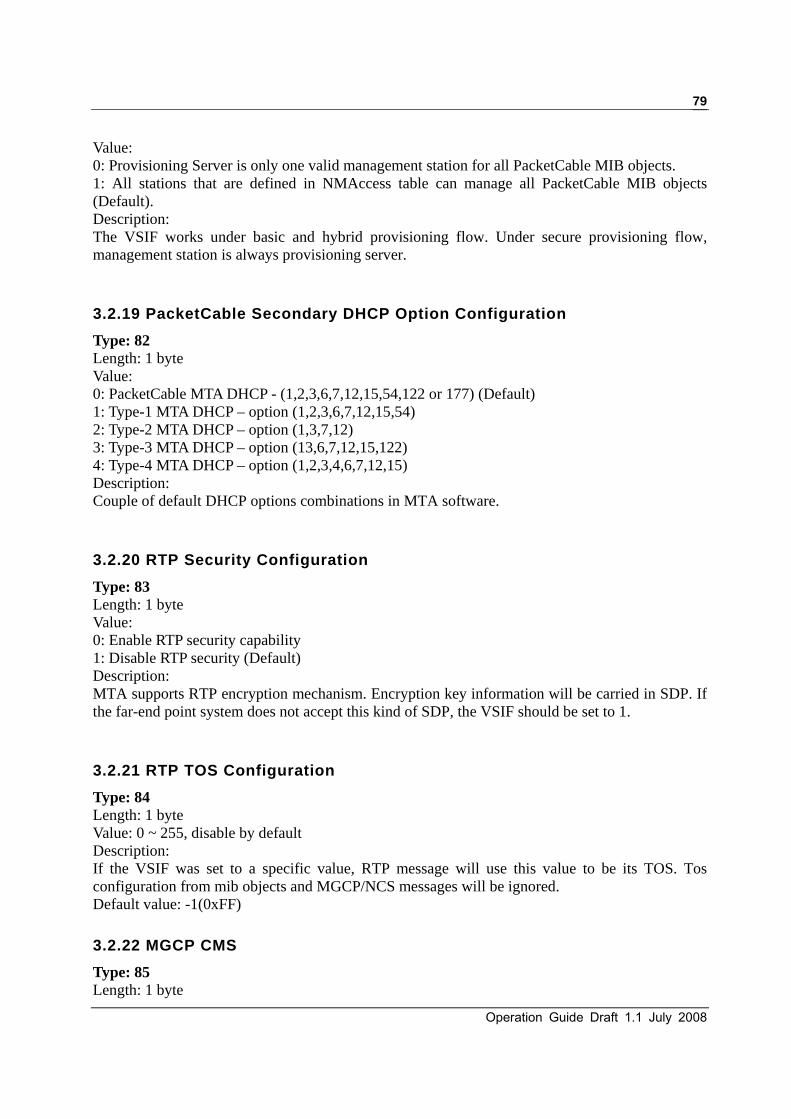
Operation Guide Draft 1.1 July 2008
79
Value: 0: Provisioning Server is only one valid management station for all PacketCable MIB objects. 1: All stations that are defined in NMAccess table can manage all PacketCable MIB objects (Default). Description: The VSIF works under basic and hybrid provisioning flow. Under secure provisioning flow, management station is always provisioning server.
3.2.19 PacketCable Secondary DHCP Option Configuration Type: 82 Length: 1 byte Value: 0: PacketCable MTA DHCP - (1,2,3,6,7,12,15,54,122 or 177) (Default) 1: Type-1 MTA DHCP – option (1,2,3,6,7,12,15,54) 2: Type-2 MTA DHCP – option (1,3,7,12) 3: Type-3 MTA DHCP – option (13,6,7,12,15,122) 4: Type-4 MTA DHCP – option (1,2,3,4,6,7,12,15) Description: Couple of default DHCP options combinations in MTA software.
3.2.20 RTP Security Configuration Type: 83 Length: 1 byte Value: 0: Enable RTP security capability 1: Disable RTP security (Default) Description: MTA supports RTP encryption mechanism. Encryption key information will be carried in SDP. If the far-end point system does not accept this kind of SDP, the VSIF should be set to 1.
3.2.21 RTP TOS Configuration Type: 84 Length: 1 byte Value: 0 ~ 255, disable by default Description: If the VSIF was set to a specific value, RTP message will use this value to be its TOS. Tos configuration from mib objects and MGCP/NCS messages will be ignored. Default value: -1(0xFF)
3.2.22 MGCP CMS Type: 85 Length: 1 byte

U10C017/22/34 Telephony Version 1.1 July 2007
80
Value: 0: MGCP/NCS CMS (Default) 1: MGCP CMS Description: If CMS does not accept “MGCP 1.0/NCS 1.0” header of signaling protocol, the VSIF should be set to 1. If the VSIF was set to 1, MTA will sent “MGCP 1.0” header of signaling protocol to CMS.
3.2.23 Crash Info Type: 86 Length: 1 byte Value: 0: Do not save crash information to L2F. (Default) 1: Save crash information to L2F. Description: MTA generates useful information when it goes to crash. If the VSIF was set to 1, crash information will be stored to L2F file for manufacturer RD. If it not necessary, the VSIF should be in default setting.
3.2.24 MGCP/NCS piggyback Configuration Type: 87 Length: 1 byte Value: 0: Disable MGCP/NCS piggyback (Default) 1: Enable MGCP/NCS piggyback Description: Some CMS does not support piggyback MGCP/NCS message. Under this case, the VSIF should be set to 0. EMTA does not sent any piggyback MGCP/NCS message to CMS but it is still able to handle piggyback MGCP/NCS message from CMS if the VSIF is set to 0.
3.2.25 MTA Debug Level Configuration Type: 88 Length: 1 byte Value: 1(00000001b): Enable DNS debugging 2(00000010b): Enable Kerberos debugging 4(00000100b): Enable MGCP/NCS debugging 8(00001000b): Enable MTA debugging Description: MTA supports module debugging features. By default, the VSIF is set to 0x0C (00001100b, NCS/MGCP and MTA debugging was on). If it is not necessary, the VSIF should not be changed.

Operation Guide Draft 1.1 July 2008
81
3.2.26 Console Input/Output Configuration Type: 89 Length: 1 byte Value: 1: Disable console input and output (Default) 2: Reserved 3: Enable console input and output Description: MTA console includes useful information for hacker. MTA disable console input and output by default configuration. If it is necessary, the VSIF can be used to enable console for debugging. 3.2.27 Enable/Disable packet period time in SDP Type: 91 Length: 1 byte Value: 0: mptime and ptime will not present in MGCP SDP 1: mptime and ptime will present in MGCP SDP (Default) Description: Configure the MTA to include/exclude mptime and ptime in SDP
3.2.28 Software reset when periodical Ranging-Abort Type: 92 Length: 1 byte Value: 0: Periodical Ranging-Abort will only re-initial DOCSIS MAC (Default) 1: Periodical Ranging-Abort will issue software reset Description: If set the value to 0, when periodical Ranging-Abort, the CM will only re-initial DOCSIS MAC driver. If set the value to 1, when periodical Ranging-Abort, the CM will issue software reset
3.2.29 Service Flow control for voice stream Type: 93 Length: 1 byte Value: 0: Create UGS/UGS-AD service flow for voice stream (Default) 1: Voice stream using best-effort service flow Description: If set the value to 0, the CM will create UGS/UGS-AD service flow for voice stream. If set the value to 1, the CM will use best-effort service flow for voice stream.
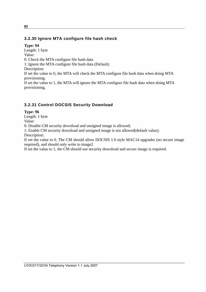
U10C017/22/34 Telephony Version 1.1 July 2007
82
3.2.30 Ignore MTA configure file hash check Type: 94 Length: 1 byte Value: 0: Check the MTA configure file hash data 1: Ignore the MTA configure file hash data (Default) Description: If set the value to 0, the MTA will check the MTA configure file hash data when doing MTA provisioning. If set the value to 1, the MTA will ignore the MTA configure file hash data when doing MTA provisioning.
3.2.31 Control DOCSIS Security Download Type: 96 Length: 1 byte Value: 0: Disable CM security download and unsigned image is allowed; 1: Enable CM security download and unsigned image is not allowed(default value); Description: If set the value to 0, The CM should allow DOCSIS 1.0 style MAC14 upgrades (no secure image required), and should only write to image2 If set the value to 1, the CM should use security download and secure image is required.

Operation Guide Draft 1.1 July 2008
83
4 Telnet CLI For U10C017 Only
The Cable modem default telnet Login User, Password and Port. For U10C017
Login: admin Password: admin Port: 23 For U10C022 Login admin Password cableroot Port: 64623 ** Note:
Cable Modem local Telnet access is 192.168.100.1 Cable Modem remote Telnet access is Cable-RF-IP-address Cable Modem remote Telnet access is WAN-IP-address (U10C022 Only) Please refer section “2.1.5 Configuring Telnet Access” to know more details
about telnet access.

U10C017/22/34 Telephony Version 1.1 July 2007
84
4.1 TIPS OF USING TELNET CLI
4.1.1 Getting Help
Entering a question mark (?) at the system prompt displays a list of commands for each command mode. To list keywords or arguments, enter a question mark (?) in place of a keyword or argument. Include a space before the ?. This form of help is called command syntax help, because it reminds you which keywords or arguments are applicable based on the command, keywords, and arguments you already have entered. CM>?
arp-storms ARP Storm configurations
battery Battery command
copy Copy command
debug Debugging functions
exec-timeout Configure login timeout
exit Disconnect
goto-ds Causes the CM to move to the Ds Freq specified
interface Interface commands
nvram NVRAM command
ping Ping specified IP address
pwd Change password
quit Disconnect
rmaccesslog Remote-access log control
reset Resetting system
show Show commands
telnet-access Telnet access control command
tracert Trace route
undebug Disable debugging functions
web-access Web access control command
write Write configuration to nvram
emta-config Configure the emta parameter

Operation Guide Draft 1.1 July 2008
85
4.1.2 Redisplaying a command
To redisplay a command you previously entered, press the up-arrow key. You can continue to press the up-arrow key for more commands.
4.2 CABLE MODEM TELNET COMMANDS
arp-storms Configure ARP storm filter to filter out upstream ARP packet Command Usage Explanation arp-storms [enable| disable] Enable or Disable arp-storm filter
arp-storms interval [seconds] Configure interval of arp-storm filter for rate limited
arp-storms limit [number] Indicate how many ARPs are allowed per interval
battery
Battery associated telnet command Command Usage Explanation battery low-battery [minutes] Battery command
[minutes] 1-1000 Configure the low battery threshold.
<Enter> Show current low battery threshold
copy Copy firmware from TFTP server to modem or upload flash-log
Command Usage Explanation

U10C017/22/34 Telephony Version 1.1 July 2007
86
copy tftp:image [tftpServerIp] [file-name] Copy modem **unsigned firmware from specified TFTP server IP address and file name
debug Debug command for CM and MTA Command Usage Explanation debug [module] Set telnet session inactivity timeout
[module] mta This command was not used anymore; it just remained user that this command has been moved to MTA command group.
exec-timeout Telnet timeout setting Command Usage Explanation exec-timeout [timer] Set telnet session inactivity timeout
[timer] 1..1440 minutes
goto_ds Command modem to lock another D/S frequency Command Usage Explanation goto_ds [D/S freq] Command modem to lock another D/S frequency. Telnet
session will be terminated after the command completed and CM/MTA will re-register to CMTA and CMS, too.
[D/S freq] D/S frequency in “hz”
interface Configure interface (Ethernet, USB and RF) startup or shutdown

Operation Guide Draft 1.1 July 2008
87
Command Usage Explanation interface [interface] [status] [option] The command is used to set interface status.
[interface] Interface can be “ethernet”, “usb” or “cable”
[status] shutdown
Shutdown interface
startup
Startup interface
speed
Ethernet interface speed (Ethernet only)
duplex
Ethernet interface duplex(Ethernet only)
autoneg
Auto Negotiation(for Ethernet only)
[option] 10
10Mbps (speed only)
100
100Mbps (speed only)
half
Half duplex (duplex only)
full
Full duplex (duplex only)
enable
Enable Auto Negotiation (autoneg only)
disable
Disable Auto Negotiation (autoneg only)
nvram Config device NVRAM setting Command Usage Explanation nvram factory-default Set all modem settings back to factory default.

U10C017/22/34 Telephony Version 1.1 July 2007
88
ping Perform Ping command Command Usage Explanation ping [Target] [options] Ping specified IP address or domain name
[options] -w Timeout in milliseconds to wait for each reply
-l Send buffer size (buffer size is between 64-1518)
passwd Change user-name password Command Usage Explanation passwd [user-name] [new-password] Change user-name password
[user-name] admin | user
quit or exit Disconnect telnet session Command Usage Explanation Quit Disconnect telnet session
rmaccesslog Remote-access log control Command Usage Explanation rmaccesslog [option] Remote-access log control
Enter Show current status of remote access log.
[user-name] enable Enable remote-access log
disable

Operation Guide Draft 1.1 July 2008
89
Disable remote-access log
reset Reset cable modem Command Usage Explanation Reset Reset cable modem
show Show cable modem status Command Usage Explanation show [option] Show device status
[option] arp-storms Display ARP Storm configurations
Battery Display battery information
cpe-info Display CPE information
cpu-utilization Display CPU Utilization
dhcp-lease Display CM DHCP information
dsx-msg Display DSX message
event-log Display CableModem internal event log
exec-timeout Display execution time out
interface
Display interface information
mem-status

U10C017/22/34 Telephony Version 1.1 July 2007
90
Display memory status
pkt-classifier Display all current classifiers and parameters
qos-param Display QoS parameters of all current service flows
sf-static Display statistics for all current service flows
Stats Display stats
system-up-time Display System up-time
telnet-access Display telnet access
User Login user(s) list
Version Display version
web-access Display web access
telnet-access Configure telnet access interface Command Usage Explanation telnet-access [interface] [option] Configure telnet access interface. This configuration will not
affect current telnet session. If modem restart itself, telnet-access will go back to original configuration.
[interface] local
telnet request is from CPE interface
remote
telnet request is from RF interface
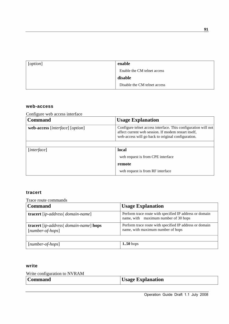
Operation Guide Draft 1.1 July 2008
91
[option] enable
Enable the CM telnet access
disable
Disable the CM telnet access
web-access Configure web access interface Command Usage Explanation web-access [interface] [option] Configure telnet access interface. This configuration will not
affect current web session. If modem restart itself, web-access will go back to original configuration.
[interface] local
web request is from CPE interface
remote
web request is from RF interface
tracert Trace route commands Command Usage Explanation tracert [ip-address| domain-name] Perform trace route with specified IP address or domain
name, with maximum number of 30 hops
tracert [ip-address| domain-name] hops [number-of-hops]
Perform trace route with specified IP address or domain name, with maximum number of hops
[number-of-hops] 1..50 hops
write Write configuration to NVRAM Command Usage Explanation

U10C017/22/34 Telephony Version 1.1 July 2007
92
Write Write configuration to NVRAM
emta-config Change to EMTA Command Group
Command Usage Explanation emta-config Change to EMTA Command Group
4.3 MTA TELNET COMMANDS
copy Download telephony root certificate to EMTA Command Usage Explanation copy tftp:tel-rootcert [tftpServerIp] [file-name] Copy telephony-root certificate from specified TFTP
server IP address and file name
countrycode Set country code Command Usage Explanation countrycode [code] Set country code. Ringing frequency, tx/rx attenuation, hookflash
time, offhook time, onhook time will be changed after new country code is applied. The modem will reset itself after new country code is applied, too.
[code] 0 = NORTH_AMERICA
1 = JAPAN
2 = UK
3 = SWEDEN
4 = GERMANY
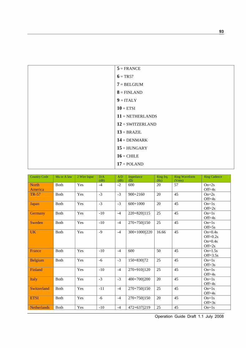
Operation Guide Draft 1.1 July 2008
93
5 = FRANCE
6 = TR57
7 = BELGIUM
8 = FINLAND
9 = ITALY
10 = ETSI
11 = NETHERLANDS
12 = SWITZERLAND
13 = BRAZIL
14 = DENMARK
15 = HUNGARY
16 = CHILE
17 = POLAND
Country Code Mu or A law 2 Wire Input D/A
(dB) A/D(dB)
Impedance (Ω)
Ring frq. (Hz)
Ring Waveform (Vrms)
Ring Cadence
North America
Both Yes -4 -2 600 20 57 On=2s Off=4s
TR-57 Both Yes -3 -3 900+2160 20 45 On=2s Off=4s
Japan Both Yes -3 -3 600+1000 20 45 On=1s Off=2s
Germany Both Yes -10 -4 220+820||115 25 45 On=1s Off=4s
Sweden Both Yes -10 -4 270+750||150 25 45 On=1s Off=5s
UK Both Yes -9 -4 300+1000||220 16.66 45 On=0.4s Off=0.2s On=0.4s Off=2s
France Both Yes -10 -4 600 50 45 On=1.5s Off=3.5s
Belgium Both Yes -6 -3 150+830||72 25 45 On=1s Off=3s
Finland
Yes -10 -4 270+910||120 25 45 On=1s Off=4s
Italy Both Yes -3 -3 400+700||200 20 45 On=1s Off=4s
Switzerland Both Yes -11 -4 270+750||150 25 45 On=1s Off=4s
ETSI Both Yes -6 -4 270+750||150 20 45 On=1s Off=3s
Netherlands Both Yes -10 -4 472+637||219 25 45 On=1s

U10C017/22/34 Telephony Version 1.1 July 2007
94
Off=4s Denmark Both Yes -11 -4 279+750||150 25 45 On=0.75s
Off=7.5s Chile Both Yes -11 -4 270+750||150 20 50 On=1s
Off=4s Hungary Both Yes -11 -4 600 25 50 On=1..25s
Off=3.75s Brazil Both Yes -11 -4 279+750||150 25 45 On=1s
Off=4s Austria Both Yes -6 -4 220+820||115 25 45 On=1s
Off=5s Porland Both Yes -6 -4 220+820||115 25 45 On=1s
Off=4s Czech Both Yes -6 -4 600 45 45 On=1s
Off=4sSlovakia Both Yes -6 -4 220+820||115 25 75 On=1s
Off=4s Ireland Both Yes -6 -4 270+750||150 25 45 On=0.4s
Off=0.2s On=0.4s Off=2s
Slovenia Both Yes -6 -4 270+750||150 20 45 On=1s Off=3s
Romania Both Yes -6 -4 270+750||150 20 45 On=1s Off=3s
debug Run-time MTA debugging functions. Command Usage Explanation debug [module][switch] Set loopcurrent to 25mA or 40mA. The command will
take effect immediately. The command also takes effect after modem power cycle.
[module] bhal
Board Hardware Adaptation Layer debugging functionsbos
OS abstraction layer debugging functions calc
Call client module debugging functions cas
Channel Associated Signaling debugging functions dhcp
DHCP module debugging functions dns

Operation Guide Draft 1.1 July 2008
95
Dynamic Name Service module debugging functions ept
Endpoint module debugging functions hbt
Hearbeat module debugging functions hdsp
Hausware DSP APIs and tones information debugging functions
krb
Kerberos module debugging functions log
The LOG module itself debugging functions ncs
NCS protocol module debugging functions net
Network module debugging functions prov
Provisioning module debugging functions rtp
Real Time Protocol debugging functions snmp
SNMP module debugging functions tpd
Line diagnostics debugging functions util
Utility module debugging functions xdrv
xChange Driver debugging functions all
All debugging functions[switch] on
Turn on the debugging function for corresponding module.
off Turn off the debugging function for corresponding module.
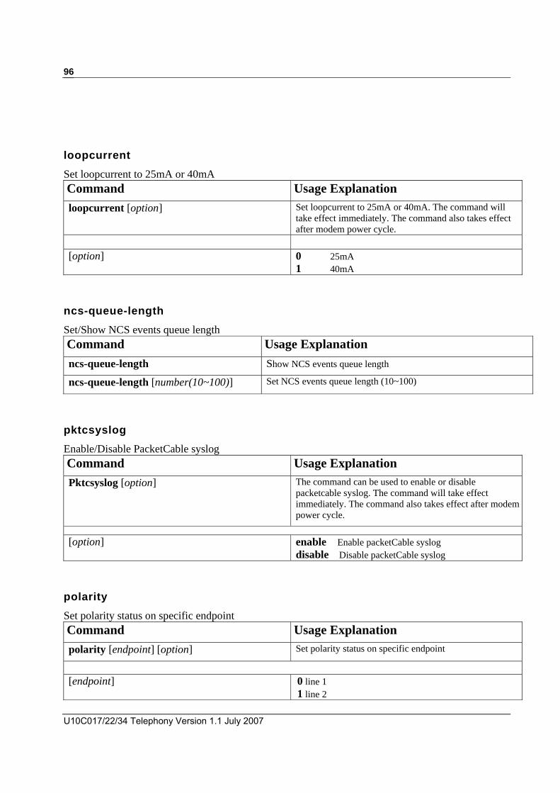
U10C017/22/34 Telephony Version 1.1 July 2007
96
loopcurrent Set loopcurrent to 25mA or 40mA Command Usage Explanation loopcurrent [option] Set loopcurrent to 25mA or 40mA. The command will
take effect immediately. The command also takes effect after modem power cycle.
[option] 0 25mA
1 40mA
ncs-queue-length Set/Show NCS events queue length Command Usage Explanation ncs-queue-length Show NCS events queue length
ncs-queue-length [number(10~100)] Set NCS events queue length (10~100)
pktcsyslog Enable/Disable PacketCable syslog Command Usage Explanation Pktcsyslog [option] The command can be used to enable or disable
packetcable syslog. The command will take effect immediately. The command also takes effect after modem power cycle.
[option] enable Enable packetCable syslog disable Disable packetCable syslog
polarity Set polarity status on specific endpoint Command Usage Explanation polarity [endpoint] [option] Set polarity status on specific endpoint
[endpoint] 0 line 1
1 line 2

Operation Guide Draft 1.1 July 2008
97
[option] 0 forward mode (ring: -48V, tip:0V) 1 reverse mode (ring: 0V, tip:-48V)
ring Start/Stop ringing signaling on specific endpoint Command Usage Explanation ring [endpoint] [option] Start/Stop ringing signaling on specific endpoint
[endpoint] 0 line 1
1 line 2
[option] 0 start ringing
1 stop ringing
show Show cable modem status Command Usage Explanation show [option] Show MTA status
Show call-statistics [statistics-option] Show call statistics information, such as RTP/RTCP statistics, mgcp-log per call, last call start/end time, etc.
show dsp-channel [dsp-option] Display current state of DSP channel
[option] call-statistics
Display call statistics information
cms-ip
Display CMS IP address
config-file
Display MTA config file
connections
Display connections status
countrycode
Display currently country code
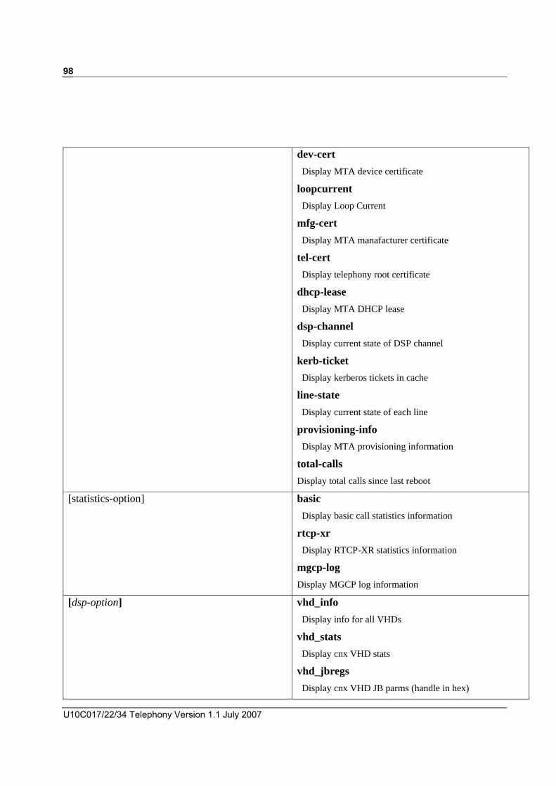
U10C017/22/34 Telephony Version 1.1 July 2007
98
dev-cert
Display MTA device certificate
loopcurrent
Display Loop Current
mfg-cert
Display MTA manafacturer certificate
tel-cert
Display telephony root certificate
dhcp-lease
Display MTA DHCP lease
dsp-channel
Display current state of DSP channel
kerb-ticket
Display kerberos tickets in cache
line-state
Display current state of each line
provisioning-info
Display MTA provisioning information
total-calls
Display total calls since last reboot
[statistics-option] basic
Display basic call statistics information
rtcp-xr
Display RTCP-XR statistics information
mgcp-log
Display MGCP log information
[dsp-option] vhd_info
Display info for all VHDs
vhd_stats
Display cnx VHD stats
vhd_jbregs
Display cnx VHD JB parms (handle in hex)
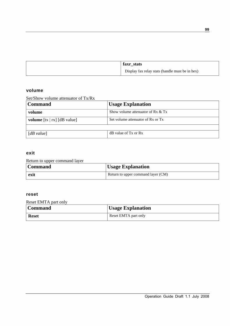
Operation Guide Draft 1.1 July 2008
99
faxr_stats
Display fax relay stats (handle must be in hex)
volume Set/Show volume attenuator of Tx/Rx Command Usage Explanation volume Show volume attenuator of Rx & Tx
volume [tx | rx] [dB value] Set volume attenuator of Rx or Tx
[dB value] dB value of Tx or Rx
exit Return to upper command layer Command Usage Explanation exit Return to upper command layer (CM)
reset Reset EMTA part only Command Usage Explanation Reset Reset EMTA part only
U10C017/22/34 Telephony Version 1.1 July 2007
100
5 U10C022 User Guide
This Chapter defines U10C022 User’s guide, please refers to U10C022 user guide for getting more information.

Operation Guide Draft 1.1 July 2008
101

U10C017/22/34 Telephony Version 1.1 July 2007
102
6 Appendix A:eMTA LED Behavior
This section describes a matrix details the U10C017/22/34 LED behavior.

Operation Guide Draft 1.1 July 2008
103
NOTE1: If the unit does not have a battery, the LED should not be lit during device initialization. If the unit does have a battery, the LED should be lit during device initialization.

U10C017/22/34 Telephony Version 1.1 July 2007
104
U10C017/22/34 Telephony Operation Guide