OfW 49 Fixed Point-to-Point and Point-to- Multipoint ...€¦ · OfW 49 Fixed Point-to-Point and...
45
OfW 49 Fixed Point-to-Point and Point-to- Multipoint Scanning Telemetry Radio Services Operating in the Frequency Ranges 457.5 to 458.5 MHz paired with 463.0 to 464.0 MHz Published: May 2017 Version: 3.0
Transcript of OfW 49 Fixed Point-to-Point and Point-to- Multipoint ...€¦ · OfW 49 Fixed Point-to-Point and...

OfW 49 Fixed Point-to-Point and Point-to- Multipoint Scanning Telemetry Radio Services Operating in the Frequency Ranges 457.5 to 458.5 MHz paired with 463.0 to 464.0 MHz
Published: May 2017
Version: 3.0

Technical Frequency Assignment Criteria 457.5 to 458.5 MHz paired with 463.0 to 464.0 MHz OfW 49
2
Foreword
The Wireless Telegraphy Act 2006 request that only radio apparatus that the Office of Communications (Ofcom) has authorised a licence for can be installed and used in the United Kingdom. This is under the condition that the radio equipment meets certain minimum standards set in the Interface Requirement 2037 (IR 2037).
This document details the technical frequency assignment criteria and principles that Ofcom has employed in the selected frequencies for use by compliant fixed terrestrial (point-to-point and point-to-multipoint) analogue radio equipment operating in the specified band or frequency range. It is further used for the basis of assessing both 1) new link applications and 2) treating technical reconfiguration of links on application form OfW 113 for scanning telemetry links.
Operators and manufacturers can obtain the latest copy of this document from the Ofcom website. If you do not have access to the internet, you can request a printed copy to be posted to you from the Ofcom Contact Centre by telephoning0300 123 3333 or 020 7981 3040.
Please see below for full contact details:
Ofcom website: www.ofcom.org.uk
Ofcom Contact Centre
Riverside House 2a Southwark Bridge Road London SE1 9HA
Tel: 0300 123 3333 or 020 7981 3040 Fax: 020 7981 3333
Email: [email protected]

Technical Frequency Assignment Criteria 457.5 to 458.5 MHz paired with 463.0 to 464.0 MHz OfW 49
Section 1
3
Contents Section Page
1 General
4
2 Channel Information
5
3 Transmitting and Receiving Installations
10
4 Principles of assignment and EIRP Derivation
16
5 Other telemetry services
28
6 Continental interference to UK scanning telemetry systems
31
Annex Page
A Transmit Frequencies for Scanning Telemetry and Telecontrol
34
B Adaptable Cellular Plan Channel Sets
37
C Adaptable Channel Plan Non-Adjacent Cell Channel Look Up Table for The Electricity Industry
38
D Adaptable Channel Plan Non-Adjacent Cell Channel Look Up Table for The Water Industry
40
E Adaptable Channel Plan Non-Adjacent Cell Channel Look Up Table for The Gas Industry
42
F Adaptable Cellular Plan Call Centre National and Irish Grid Reference Co-Ordinates
44

Technical Frequency Assignment Criteria 457.5 to 458.5 MHz paired with 463.0 to 464.0 MHz OfW 49
Section 1
4
General
1.1 Introduction
This document outlines the technical frequency assignment criteria and principles that Ofcom will employ when selecting frequencies for fixed terrestrial (point-to-point and point-to- multipoint) analogue and digital radio services operating in the frequency band 457.5 to 458.5 MHz paired with 464.0 to 465.0 MHz.
Please refer to section 5 for the applied channel plan.
1.2 Licensee's responsibility
The establishment, use or installation of transmitting or receiving apparatus is subject to the issue of a licence by Ofcom. The licensee must ensure that equipment conforms with and is kept to the requirements referenced in UK IR 2037.
1.3 Minimum path length policy
Please see section 4.5.
1.4 References
Ref.
No:
Title Author Year
1 Void
2 Radio Interface Requirements 2037 – Scanning telemetry and telecontrol Systems operating in the frequency band 457.5 to 465.0 MHz in which spectrum managed by Ofcom. (EC Notification Number:2001/130/UK)
Ofcom 2001
3 The Future of UHF Scanning telemetry and telecontrol Frequency Assignments - A report for DTI, Joint Radio Committee (JRC) and Technical Advisory Group (TAG)
Ofcom January 1989

Technical Frequency Assignment Criteria 457.5 to 458.5 MHz paired with 463.0 to 464.0 MHz OfW 49
5
Section 2
Channel Information 2.1 Adaptable cellular plan
The Adaptable Cellular Plan (Adaptable Channel Plan) was devised as a means of maximising the use of the scanning telemetry and telecontrol band and providing a defined planning and frequency co-ordinating environment for the major utilities of scanning telemetry and telecontrol; namely the Gas, Electricity and Water industries. A full description and discussion of the Adaptable Cellular Plan is given in the reference [3].
The UHF scanning telemetry and band comprises of 80 channels, 72 of which are reserved for use with the Adaptable Cellular Plan. The 72 channels are arranged on a twelve cell, six channels per cell, regular frequency re-use plan. Each of the three utilities has access to two exclusive channels per cell. Eight channels (T73 to T80) are reserved for other users of scanning telemetry services and these are not subject to the Adaptable Cellular Plan.
The use of alternative planning and frequency co-ordination strategies by one or more of the aforementioned utilities, within their own allotted channels is permitted by Ofcom, providing that prior agreement is achieved and its effectiveness over the present arrangement can be adequately demonstrated.
The basic parameters of the plan, are:
system availability approaching 99·9%;
four classes of outstation, based upon their data transmission speeds and C/I ratio (see table 5).
cell radii of 25 km, but outstations with path lengths of up to 30 km are allowed in the first instance, with longer paths permitted on a case-by-case basis.
6 channels per cell, giving 2 channels per utility;
12 cells per cluster, giving a co-channel re-use distance of 150 km; and
potential channel re-uses of 23 times across the UK.

Technical Frequency Assignment Criteria 457.5 to 458.5 MHz paired with 463.0 to 464.0 MHz OfW 49
6
The distribution of channels between the three major utility operators of scanning telemetry systems on a per cell basis is shown in Table 1 below:
Cell Gas Electricity Water
Ch.1 Ch.2 Ch.1 Ch.2 Ch.1 Ch.2
A 57 59 3 12 44 47
B 69 65 32 6 21 36
C 48 50 29 40 31 56
D 49 51 13 24 14 16
E 64 66 27 7 30 37
F 60 62 41 25 35 45
G 70 72 10 11 19 17
H 61 63 9 34 38 46
J 52 54 23 28 5 15
K 67 58 2 33 1 39
L 68 71 8 26 20 43
M 53 55 4 42 18 22
Table 1: Distribution of channels between the three major utility operators
The cellular re-use strategy is illustrated in figure 1 and the cell centres are listed in Annex F.

Technical Frequency Assignment Criteria 457.5 to 458.5 MHz paired with 463.0 to 464.0 MHz OfW 49
7
Figure 1: UK Cellular Plan for Scanning Telemetry and Telecontrol Services for the Utilities.

Technical Frequency Assignment Criteria 457.5 to 458.5 MHz paired with 463.0 to 464.0 MHz OfW 49
8
T8
T7
2.2 Maritime use of the Scanning Telemetry and Telecontrol band
The use of on-ship communications is permitted in coastal waters, estuaries and tidal rivers for maritime safety purposes. Three 25 kHz channels are available for this service and these encompass the following channels inclusively; T2 to T7. Consequently, these channels may not be assigned in areas subject to maritime traffic. Table 3 below shows the maritime channels in relation to the standard 12.5 kHz channel plan. See clause 4.2 for further details.
457.60 MHz
Scanning telemetry and telecontrol Maritime
On-Board Communications
457.59 MHz 457.58 MHz 457.57 MHz 457.56 MHz 457.55 MHz 457.54 MHz 457.53 MHz 457.52 MHz 457.51 MHz 457.50 MHz
T6
T5
T4
T3
T2
T1
12.5 kHz channels
457.575 MHz
457.550 MHz
457.525 MHz
25 kHz channels
Table 3: 25 kHz Maritime channels in relation to the 12.5 kHz channel plan
Notes: * New maritime channels (UK, as defined by Ofcom)
# New maritime channels (International, as defined by the ITU-R)

11
Section 3
Transmitting and Receiving Installations 3.1 General
The installations shall be in accordance with good engineering practice and conform to the advice within this document.
3.2 Antennas
The primary concern is for the transmitting antenna of a station, since radio emissions have the greatest potential to affect other users. In principle, it will be possible to use any antenna, or configuration of antennas for receive purposes without needing type approval, providing it can be co-ordinated with both co-channel and adjacent channel users, and meets the cross- polar rejection requirement. This should also extend to the use of more complex arrangements, such as passive or active cancellation techniques for the rejection of unwanted co-channel signals. The receive antenna configuration and its radiation pattern will however need to be registered with Ofcom, and acceptance for registration will still depend on successful frequency co-ordination with other co-channel systems. Note that frequency assignments will be made on the assumption that all antennas comply with the parameters described in the clauses below.
3.2.1 Antenna directivity
The co-polarised and cross-polarised directivity of an individual antenna installed at the licensed premises shall be such that the effective isotropic gain in the horizontal plane (0° elevation) at any azimuth does not exceed the value specified in reference [2].
3.2.2 Directional antenna arrays
Complex directional arrays of type approved antennas will be considered on a case-by-case basis.
3.2.3 Antenna nulling techniques
Active and passive antenna nulling techniques and their arrays will be considered on a case- by-case basis.
3.2.4 Antenna discrimination
When assigning frequencies, which are in use in the same geographical area, due consideration shall be taken of the antenna discrimination available where this is deemed possible.
3.2.5 Antenna polarisation
The emissions’ polarisation plane will be specified by Ofcom for each radio link.
It will normally be vertical or horizontal linear polarisation.
The antenna alignment surface will be as precise as possible to the true vertical or true horizontal.
The misalignment will be limited to 1.5.
3.2.6 Mixed polarisation systems
The use of vertical transmit and horizontal receive polarisation at the scanner for the purpose of improving system resilience is permitted. The use of mixed polarisation receive antenna systems at the scanner for unusual circumstances, e.g. due to re-direction of outstations, is

12
permitted. A typical example would be the normal system being vertically polarised, perhaps a more distant, possibly re-directed, outstation being ‘pulled-in’ by means of a horizontally polarised, with say twelve element, Yagi antenna. Such scenarios will be considered on a case-by-case basis.
3.2.6.1 Horizontal polarisation
The use of horizontal polarisation can be of benefit in a number of circumstances; whether this is for receive purposes only, where separate transmit and receive antennas are used at all sites in the system, or for combined transmit and receive where shared antennas are used. The former would result in a mixed polarisation scheme.
The use of horizontal polarisation can give between 6 dB and 15 dB polar discrimination protection against the interfering signal. Operators in the south east of England have found this to be particularly beneficial. However, the longer the path length of the interfering signal, the more likely it is to suffer greater depolarisation and hence the lower protection figure may apply. However, care needs to be exercised in areas of flat terrain as excessive ground reflections may occur. Such scenarios will be considered on a case-by-case basis.
3.2.6.2 Choice of outstation antenna
A 12-element Yagi is the minimum specification outstation antenna from the viewpoint of frequency management, spectrum conservation and good engineering.
Other antennas may be considered where appropriate and their possible use is discussed in section 6.
Ofcom will encourage any operator to use the higher performance antennas, such as an 18 element Yagi antenna with a forward gain of 16·7 dBi. These antennas will be particularly useful for re-directed outstations. 3.2.7 Specification Limits
It is assumed for planning purposes that the antenna meets the minimum requirements specified in Table 4 below.
Antenna Type Limits
Base Station Omni-directional The radiation pattern when measured in azimuth shall not vary by more than 1.5 dB for horizontally and vertically polarised antennas.
Base Station Sector coverage See Figure 2
Outstation Directional See Figures 3 and 4
Table 4: Antenna Radiation Pattern Envelope Limits

13
Figure 2: Sector Antenna Radiation Pattern Envelope for Base Stations
Angle of azimuth relative to the main beam axis 00 ( degrees)
Under Test Range Conditions
Gain relative to an isotropic antenna (dBi)
Gain relative to a half-wave dipole (dBd)
14
12
10
8
6
4
2
0
-2
-4
-6
-8
-10
12
10
8
6
4
2
0
-2
-4
-6
-8
-10
0 20 60 80 100 120 140 160 180
-6.2
-8.2
7.8
Co-Polarised Response
Cross Polarised Response
40 45

14
Figure 3: Antenna Radiation Pattern Envelope for Outstations – High Performance Antenna
Angle of azimuth relative to the main beam axis 00 ( degrees)
Under Test Range Conditions
Gain relative to an isotropic antenna (dBi)
Gain relative to a half-wave dipole (dBd)
14
12
10
8
6
4
2
0
-2
-4
-6
-8
-10
12
10
8
6
4
2
0
-2
-4
-6
-8
-10
0 40 60 80 100 120 140 160 180
-6.2
-8.2
11.5
Cross Polarised Response
Co-Polarised Response
1.8
12 20
13.7

15
Figure 4: Antenna Radiation Pattern Envelope for Outstations – standard antenna
Under Test Range Conditions
Gain relative to an isotropic antenna (dBi)
Gain relative to a half-wave dipole (dBd)
14
12
10
8
6
4
2
0
-2
-4
-6
-8
-10
12
10
8
6
4
2
0
-2
-4
-6
-8
-10
0 20 40 60 80 100 120 140 160 180
-6.2
-8.2
8.8
1.8
Co-Polarised Response
Cross Polarised Response
15 30
11
Angle of azimuth relative to the main beam axis 00 ( degrees)

16
Section 4
Principles of Assignment and EIRP Derivation 4.1 Background
In the interest of economy of use of the radio frequency spectrum and of limiting interference between different radio transmissions, it is the responsibility of Ofcom to decide the frequency assignment, the limits of EIRP and other engineering characteristics to be permitted under the licence for each separate or group of radio installations.
Factors, which may affect the most suitable frequency, include the antenna polarisation, antenna heights, and the end-to-end circuit loss of potential interference paths, together with the Adaptable Channel Plan. An assessment may also include site inter-modulation products etc, before the final frequency assignment is decided. Furthermore, when assigning frequencies in the same geographical area, due consideration is given to available antenna discrimination when this is deemed possible.
4.2 Frequency channelling
The bands 457·5 to 458·5 MHz and 463·0 to 464·0 MHz may be considered as a lower half band "L" and an upper half band "H" respectively.
A frequency assignment will generally comprise of a channel comprising a pair of transmit frequencies. One frequency chosen from the "L" half band will be assigned to the base station (scanner) and the corresponding frequency from the "H" half band to the outstation.
The frequency difference between two adjacent channels in both the "L" and "H" half bands will be 12·5 kHz and the difference between a pair of corresponding "L" and "H" channels will be 5·5 MHz (See Annex A).
Wherever possible frequency re-use will be employed. In the case of channels T1 to T72, this will be in accordance with the Adaptable Cellular Plan where possible. Please refer to Table 1.
A total of 15 channels have been identified as nominally interference free on account of their offset from adjacent continental cellular radio channels. Where feasible, the scanners in interference prone areas will be assigned on these channels. However, there can be no guarantee that any channel will remain free from continental interference in the future. These channels are;
2, 7, 10, 15, 18, 23, 26, 31, 34, 39, 42, 47, 58, 63 and 74.
Channels shared with the Maritime Service will not be assigned in coastal areas and estuaries. These channels are shown in Table 3.
4.3 Co-channel interference limits
Ofcom will, as far as possible, assign frequencies on the basis that a wanted Carrier to Co- Channel Interference ratio (C/I) from table 5 relating to the applicable class of outstation . Which in normal circumstances, for a single unwanted source at the receiver input, should not exceed -144 dBW for 99·9% of the time.
For co-ordination purposes, the EIRP is that radiated in the horizontal plane (0° elevation).
It is important that the wanted Carrier to Co-Channel Interference (C/I) ratio between the existing co-channel operators and the applicant’s systems should be maintained. The applicant’s EIRP’s should not degrade the co-channel operators’ C/I ratios, however it may

17
be that an acceptable degradation could be negotiated with the co-channel operator(s) which will permit increased EIRP’s for the applicant. It will be the applicant’s responsibility to demonstrate that a satisfactory agreement has been reached with the co-channel operator(s).
Outstation
Class Data Rate
(kBit/s) Sensitivity 10-2 (dBm)
Unfaded Signal (dBm)
Faded signal (dBm)
C/I ratio (dB)
1 9.6 -110 -92 -102 22 2 16 -105 -87 -97 27 3 38 -98 -80 -90 34 4 >38 -93 -75 -85 39
Table 5: Outstation class, Receiver parameters and C/I ratio
a. Channel selection and assignment
For applicants, other than the Gas, Electricity and Water Industries, the choice of frequency to be assigned to the system(s) will depend on the ability of Ofcom to co-ordinate a channel, selected from within channels T73 to T80, with existing co-channel operators. In the case of a multi-site scheme, the re-use of a chosen frequency within the scheme may be necessary.
In the case of the Gas, Electricity and Water Industries, the assignment will generally be in accordance with the Adaptable Cellular Plan. These channel allocations are shown in table 1. Where it is not possible to select a channel from table 1 which is appropriate to both the cell and the applicant’s industry, (which may be due either to existing assignments or maritime operations, or where it is required to import channels to satisfy increased demand for services), a channel will need to be selected by one of the following criteria:
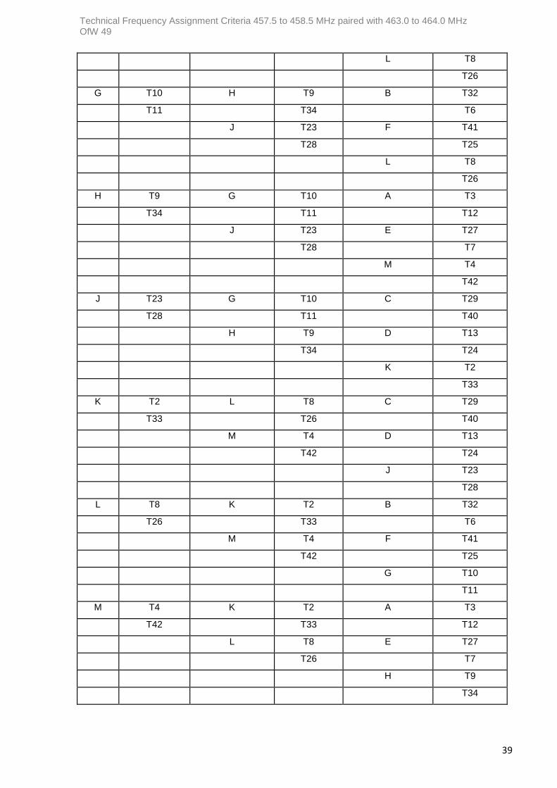
Where there is a high density of scanning stations and it is either inappropriate, or not possible, to use an adjacent cell channel, then a channel can be selected from either the first or second tier non-adjacent cells. The selection criteria are shown in Annexes E, C, and D for the Gas, Electricity and Water Industries respectively. For instance, if the home cell is ‘A’, the first tier channels for the gas industry will be T48, T50, T65 and T69, the second tier channels will be T53, T55, T61, T63, T64 and T66.
Where the density of existing scanning stations is low, or where the proposed site is on, or adjacent to, a coastal area, then it may very well be possible to import a channel from an adjacent sea-bound cell. However, the importing may result in the sterilisation of the adjacent donor cell, thus preventing the full capability of the Adaptable Channel Plan being realised in that area.
With the above selection processes, the use of a channel will generally be at a lower EIRP than usual because of the reduced co-channel frequency re-use distance. The use of imported channels may require both the adoption of a polarisation orthogonal to that used in the channel’s home cell and directional scanner antennas. If either channel selection process fails to identify a suitable channel, then it may be possible to assign one from another industry’s group of channels, providing this can be successfully negotiated with the donor industry. In all cases, the choice of channel must be co-ordinated with existing co-channel systems.
b. Link length policy
In the interests of spectrum efficiency, Ofcom will generally consider only those outstations, whether standard, non-standard or relay, which are grouped within a 30 km radius of the associated base station. Outstations greater than 30 km from the base station will only be considered on a case-by-case basis. This provision is to enable those outstations whose path lengths cannot readily be kept below 30 km, due to either practical or external constraints, or any procedure that has been adopted to ameliorate the effects of continental interference. Such outstations will need to be successfully frequency co- ordinated with other users and must comply with the planning assumptions stated within this Technical

18
Frequency Assignment Criteria document.
c. Equivalent isotropically radiated power (EIRP)
The maximum value of EIRP will be a condition of the licence. In no circumstances will Ofcom issue a licence for any system which requires an EIRP in excess of 250 W (24 dBW).
d. Total path loss
The total path loss is the sum of the free space propagation, ground terrain obstruction and building and vegetation clutter losses. In general, computer based prediction methods use the first two; however, some models also predict clutter losses as well. The terrain obstruction loss may be zero for some paths, this may also be the case for clutter loss. The losses may alternatively be manually calculated. The various elements of the path loss are shown in figure 5.
Total path loss = free space path loss + terrain obstruction loss + building and vegetation clutter loss
(The free space loss is that which corresponds to a first Fresnel zone clearance of 0·6, using an earth curvature factor of K=4/3).
Figure 5: Losses along a path
The total path loss for assignment purposes may not exceed 143 dB under any circumstances. If it does so, the value used for assignment purposes will be restricted to 143 dB.
i. Clutter loss
Clutter losses comprise of the following components:
The loss due to the effects of buildings and vegetation on top of a terrain obstruction along the path.
The loss due to buildings and vegetation in the immediate locality of the outstation. The clutter loss near an outstation may comprise of one or both of the above two components as illustrated in Figure 5.
In order to encourage operators to minimise excessive local clutter, the specification limit for clutter loss shall be 20 dB, although losses up to, but not exceeding, 30 dB will be considered on a case-by-case basis.
Where clutter losses exceed 20 dB, supporting documentation will be required which shall

19
indicate the cause of the excess clutter and confirm that all reasonable attempts have been made to minimise local clutter effects.
For existing systems, this limitation will only apply when the inclusion of additional outstations require an increase in the scanner EIRP. This limitation will apply to all new systems.
The clutter loss may be estimated by a database, calculated by a computer prediction model in conjunction with a terrain height database. It may also be determined by the actual measurement of the end-to-end circuit loss. This measured value will include further losses which will be comprised of the difference between the computer generated path profile and the actual path profile together with antenna radiation pattern anomalies created by its support structure. Experience indicates that clutter losses of up to 20 dB are relatively common, and up to 30 dB is sometimes unavoidable.
Any outstation whose measured path loss includes more than 20 dB of clutter ought to be re- engineered, where practicable, so as to reduce the clutter loss. This could be achieved by increasing antenna height and / or changing its spatial location on the site. There may be occasions when this is not possible, in which case the outstation may suffer poorer performance if the EIRP necessary to overcome the clutter loss cannot be successfully co- ordinated with existing co-channel systems. It will be the clutter losses in the locality of the outstation which are most likely to be reduced by the re-engineering of the outstation. For practical assigning purposes, clutter loss is defined as the difference between the Ofcom predicted and operator measured path losses (the path loss being extracted from the measured end-to-end circuit loss).
4.8 End-to-end circuit loss
In order to optimise frequency re-use, it is necessary to keep scanner and outstation EIRP’s to the minimum compatible with achieving the system performance objective. This has in the past been achieved by limiting the total path loss. However, this does not take into account factors such as the antenna characteristics, or feeder loss, which could lead to significant increases in EIRP levels.
Figure 6 – System Block Diagram With reference to figure 6, the end-to-end circuit loss comprises of the sum of all losses and gains between the transmitting station transmitter output port (C') and the receiving station receiver input port1 (C), inclusive of both stations’ antenna radiation pattern in the direction under consideration.
Where:
The antenna gain is that gain along the direction of the path, as defined by the radiation patterns.
EECL = TPL + (SFL + SOL – SAG) + (OFL + OOL - OAG)
1The receiver input port shall include any antenna combination or branching elements which may be used between the antenna feeder connections and the receiver unit input connection.

20
EECL = Scanner to outstation end-to-end circuit loss (dB).
TPL = Total path loss to the outstation (dB).
SFL, OFL = Scanner and outstation feeder losses respectively (dB).
SOL, OOL = Scanner and outstation other2 losses respectively (dB)
SAG, OAG = Scanner and outstation antenna gain respectively (dBi).
Parameter Value Comments
Sc Ant Gain 8.1 dBi {6 dBd colinear}
Sc Losses 3.0 dB {Feeder, feeder tail and connectors}
Sc Rx Level dBW {Duplicated scanner receivers with a common antenna – see table 5}
O/S Ant Gain 14.1 dBi {12 element yagi (12 dBd)}
O/S Losses - dB {see table below}
O/S Rx Level dBW {Non-duplicated outstation receivers – see table 5}
Outstation Free Space
Loss
Obstruction Loss
Clutter Loss
Total Path Loss
Outstation Losses
End to end Circuit
Loss
OS08 98.9 0.0 11.2 110.1 3.0 93.9
OS02 103.8 0.0 8.3 112.1 2.0 94.9
OS09 104.9 0.5 9.7 115.1 2.0 97.9
OS10 107.4 0.0 9.7 117.1 2.0 99.9
OS04 104.0 1.8 11.6 117.4 2.0 100.2
OS11 101.0 0.0 16.1 117.1 3.0 100.9
OS01 110.5 2.4 5.2 118.1 2.0 100.9
OS06 103.1 0.0 18.0 121.1 3.0 104.9
OS03 107.9 2.0 13.2 123.1 2.0 105.9
OS07 105.0 0.0 18.1 123.1 2.0 105.9
OS05 107.9 1.2 16.0 125.1 2.0 107.9
OS13 108.1 0.8 16.2 125.1 3.0 108.9
OS14 104.2 1.2 26.7 132.1 3.0 115.9
OS12 107.2 3.0 24.9 135.1 2.0 117.9
2 Other losses are namely, connector and feeder tail losses etc.

21
Parameter Calculated
Value
Comments
Mean EECL 104.0 Mean of all end-to-end circuit losses.
Standard Deviation (SD)
6.8 Standard Deviation (total population) of all end-to-end circuit losses.
1.6*SD + Mean
114.9 Maximum value of end-to-end circuit loss for assignment purpose.
Table 6: A Worked Example for Determining the Assignment Path
Parameter Value Unit
Scanner ‘other’ loss (Connectors etc.) 1 dB
Scanner feeder loss (Antenna at 50m agl assumed) 3 dB
Scanner antenna gain (Omni-directional assumed) 2 dBi
Maximum overall loss 143 dB
Outstation antenna gain (12 element Yagi assumed) 14 dBi
Outstation feeder loss (Antenna at 8m agl assumed) 2 dB
Outstation ‘other’ loss (Connectors etc) 1 dB
Maximum end-to-end circuit loss 134 dB
Table 7: Typical values of components
The reference values chosen are from typical systems and are based on those used in reference [3].
The values are not limiting values, except that the total end-to-end circuit loss shall not exceed 134 dB and the total path loss shall not exceed 143 dB.
4.9 Assigning path
The method for determining the assigning path and hence the maximum outstation EIRP is described below. The Standard Deviation of the scanner’s own family of outstation end-to-end circuit losses, multiplied by 1·6, will be used to provide an offset value. This offset value is then added to the mean end-to-end circuit loss to enable the maximum assignable end-to-end circuit loss (EECLmax) for the group of outstations to be determined. The assigning path defines the EECLmax which will be allowed for that particular system.

22
i
The assigning path is that path whose end-to-end circuit loss (EECL) does not exceed the calculated maximum outstation permissible value EECLmax for that system. Those paths whose actual EECL exceeds EECLmax will be assigned EIRPs corresponding to EECLmax. The EECLmax is defined thus:
Where: The above criteria will apply to existing schemes when an alteration to the system results in an increase of scanner EIRP.
EECL = The standard deviation of the end-to-end circuit losses (dB).
X EECL = The average end-to-end circuit loss for the outstations (dB).
n = The number of outstations attached to the scanner.
EECLmax = The maximum end-to-end circuit loss for the outstations (dB).
In the worked example shown in Table 8, two outstations are excluded from having their desired EIRP. However, if the OS14 outstation end-to-end circuit loss, by means of a better feeder, can be reduced by 2 dB to 113·9 dB, only one outstation will be excluded. If the
OS14 outstation end-to-end circuit loss is reduced by 5 dB to 110·9 dB (3 dB total path loss and 2 dB feeder loss) and the OS12 outstation end-to-end circuit loss is reduced by 6 dB to 111·9 dB (5 dB total path loss and 1 dB feeder loss), then no outstations are denied their desired EIRP. Reduction of the end-to-end circuit loss by means of an appropriately engineered system is the key to maximising the number of outstations which can be assigned their required EIRP. In a well-engineered system this usually includes all the outstations.

23
4.10 Path profile
To determine the maximum radiated power for both base station and associated outstations, Ofcom will require a suitably scaled path profile corresponding to an effective earth radius to real earth radius of K = 4/3. The profile shall show the path having the assigning end-to-end circuit loss as defined in clause 4.8. Details of terrain features such as vegetation, buildings, etc, must be clearly identified along with their relative positions and heights.
4.10.1 Receiver input port signal level
Scanning telemetry systems shall be so designed that the receiver input port level will be in line with the level for the applicable outstation class from table 5 for both unprotected equipment and duplicated stations utilising individual receive antennas, and -5 dB higher than these values for those operators using duplicated receivers with a common antenna. Outstations with end-to-end circuit losses that are less than the calculated maximum end to end circuit loss will benefit from a higher received signal at the receiver input port. A scanner receiver input port level of up to, but not exceeding, -103 dBW may be permitted in special circumstances. These will be considered on a case-by-case basis, the actual value being determined by the received level of continental interference and by what other ameliorating measures have been adopted by the operator.
New schemes to be installed in parts of the UK that are susceptible to interference, for example, south east of England, may be assigned higher receive signal levels than those specified in table 5 in the first instance.
In general, operators will be dissuaded from simply seeking EIRP increases and encouraged to implement more appropriate methods of engineering their system. Increased receiver input port levels will only be assigned upon the operator providing adequate evidence of the duration and magnitude of the received continental interfering signal levels, together with a statement of what other ameliorating measures the user intends to adopt to assist in combating this interference. The new levels assigned will be chosen so as to overcome the continental interference in conjunction with other practicable changes that will make the system more resilient. It may be that they will be allowed greater increases of scanner receiver input port level, and hence EIRP, for a short period of time during periods of severe interference or while other improvements are being implemented. It is accepted that there may be occasions when increased scanner receiver input port levels, and hence EIRP’s, may be the only practicable solution.
Note: The use of these higher EIRP’s will be subject to satisfactory co-channel frequency coordination. This may require the operator, requesting these increased levels, to negotiate with the co-channel users and possibly paying for the modification of the other user’s system so as to prevent it from suffering interference as a consequence of the operator’s increased EIRPs.
The application of the receiver input port levels within a system is shown in Figure 7. These are examples of the configurations most commonly employed.

24
Scanner and Outstation Configurations
Note: The receiver levels in the diagrams above are for Outstation Class 1, for other Outstation classes these values will be different, refer to table 5 for more details.
Figure 7

25
4.11 Calculation of equivalent isotropically radiated power (EIRP)
The maximum system EIRP will be calculated using the greatest total path loss permitted by the limiting end-to-end circuit loss determined by the method described below. The end to end circuit loss (EECL) comprises the total path loss + feeder losses + other losses – antenna gains in the direction under consideration. The free space and terrain obstruction loss value may be obtained by computer prediction, which may include a generalised figure for building / vegetation clutter loss.
Alternatively, the EECL may be directly measured. This measured value will include a further additional loss which will be composed of the difference between the computer-generated path profile and the actual path profile together with antenna radiation pattern anomalies created by its support structure, as well as all those parameters previously defined for the EECL. It is assumed that the operator has already satisfied himself that the installations are fault free and that the measurements are taken in a prescribed manner.
When measurements are taken, it is usually the EECL that is measured and hence these values may be used directly. However, they will be compared with the predicted EECLs to examine the extent of the clutter loss. If this exceeds 20 dB, Ofcom will investigate the application more closely; this may involve a site visit. The assigning process can then continue when the above investigation has taken place, as is current practice for the path loss.
The method for determining the maximum system EIRPs now fully characterises a scanning telemetry system and thus ensures that no parameter need be excluded when applying the limiting rule. This gives the operator more flexibility in ‘fine tuning’ their system to bring all, or most, of the outstations within the assigning rule.
Calculation of the permitted maximum EIRP will be based on the appropriate receiver input port level, as defined in clause 4.10.1, and the EECL, as defined in clause 4.8, for both the base station and -outstations and the appropriate loss to scanner or loss to outstation as shown below:
Scanner {EECLwc ≤ EECLmax LTO EECL SFL SOL SAG EIRPScanner RIL LTO
Scanner {EECLwc EECLmax LTO EECLmax SFL SOL SAG EIRPScanner RIL LTO
Outstation {EECL ≤ EECLmax LTS EECLOFL OOL OAG EIRPOutstation RIL LTS
Outstation {EECL EECLmax LTS EECLmax OFL OOL OAG EIRPOutstation RIL LTS
Where:
EECLwc Worst case outstation EECL (dB)
LTO Loss to outstation (dB).
LTS Loss to scanner (dB).
RIL Receiver input port level (dBW).
The maximum assignable EIRP for a given scanner and its family of outstation(s) is that EIRP determined by clause 4.6.
The minimum assignable EIRP will normally not be less than -20 dBW, although lower EIRPs can be assigned.

26
Parameter Value (dBW)
Scanner EIRP
-2
Outstation EIRP (dBW)
Desired Assigned
OS08 -12.0 -12.0
OS02 -10.0 -10.0
OS09 -7.0 -7.0
OS10 -5.0 -5.0
OS04 -4.7 -4.7
OS11 -5.0 -5.0
OS01 -4.0 -4.0
OS06 -1.0 -1.0
OS03 1.0 1.0
OS07 1.0 1.0
OS05 3.0 3.0
OS13 3.0 3.0
OS14 10.0 9.0
OS12 13.0 10.0
Table 8: The application of EIRP to the example shown in Table 7
Where no measured end-to-end circuit or path losses are provided, then the clutter losses will not be known and the assignment will be based on computer predicted end-to-end circuit losses only. Some computer models may estimate the prospective clutter losses, in which case an improved assignment will follow. This does not preclude a user from applying for a re-assignment using measured values at a later date once his system has been commissioned; or from seeking a temporary channel to permit a survey of preferred receive signal levels for a new scanner in advance of the full application
Under normal circumstances, the EIRP that a scanner or outstation will be assigned will be limited to a minimum of -20 dBW, even though the calculated EIRP may be lower. There may be occasions where the assigned EIRP will be less than -20 dBW.
The EIRP of the system will be calculated for each outstation and the scanner in the normal manner; in that the outstation EIRP is set so as to give the correct receiver input port level at the scanner, except that the maximum assignable EIRP is set by the method described below.
The scanner EIRP is determined from the ‘loss to outstation value (LTO) and the outstation receiver input port level, as defined above.
The outstation EIRP is determined from the ‘loss to scanner value (LTS) and the scanner receiver -input port level (RIL), as defined above.
It must be noted that when the end-to-end circuit loss (EECL) for a scanner-outstation pair exceeds the calculated maximum end-to-end circuit loss (EECLmax) value, then this value is substituted for the measured, or predicted, EECL in the modified loss- to

27
-scanner and loss- to- outstation formulae. It is this substitution which limits the EIRP which may be assigned to outstations with large EECLs, relative to the remainder of the outstations.
In the example in table 6, this results in outstations OS12 and OS14 being restricted to EECL of 114·9 dB for assignment purposes, rather than their actual end-to-end circuit loss of 117·9 and 115·9 dB. This EECLmax for the family of outstations results in loss- to -scanner values of 127 and 126 dB for OS12 and OS14 respectively and a loss- to- outstation value of 120 dB.

28
Section 5
Other Telemetry Services
It is considered that there are six basic classes of scanning telemetry and telecontrol system. These are:
Systems with standard outstations only.
Systems with both standard and non-standard outstations.
Systems with only non-standard outstations.
Single hop relay systems for circumnavigating severe obstructions.
Single standard outstation scanning telemetry systems for obstructed paths.
Multi-hop single frequency relay systems.
The following special systems fall within one of the above categories and consequently this governs their method of assignment.
5.1 Relay outstations
Ofcom will permit the use of relay outstations as a means of communicating with other outstations that are difficult to reach. This technique is already used by some non-utility operators. In effect, a relay outstation becomes a secondary scanner to communicate with one or more other outstations, which cannot be reached from the main scanner. The relay outstation will onward route the transmission using either the parent scanners transmit frequency or an alternative channel. Such relay outstations may only be used where they form an extension to a main telemetry scheme. The relay outstation will utilise antennas designated for outstation or scanner sector use and the antenna height above ground may not exceed 15 metres. The calculated EIRP will in many cases be below -20 dBW, but, where possible, a minimum EIRP of -20 dBW may be assigned. The relay outstation shall not be more than 30 km from the parent scanner.
The assigning path is determined in accordance with clauses 4.9. Non-standard outstations, as described in clause 5.4, are included in the calculations used to determine the assigning path. The calculation of the permitted maximum EIRP for the system shall be in accordance with clauses 4.6 and 4.11, except that the maximum assignable EIRP of the relay outstation and its corresponding target outstations, regardless of whether the target outstations are standard or non-standard, shall not exceed 0 dBW.
Relay outstations are not intended as an alternative to the establishment of a main scanning site, but to give access to isolated outstations where the establishment of a new main scanner site is not practicable.
Such relay outstations, together, with their target outstations, would have to be successfully frequency co-ordinated with all co-channel systems before an assignment could be made.

29
5.2 Regulated on-site and local area telemetry and telecontrol services
Ofcom will permit the use of regulated scanning telemetry and telecontrol services for on-site and local area schemes. Major user groups may reserve one or more of their allocated channels for such a service if considered appropriate. Service areas of up to 1 km are envisaged. The antenna height above ground shall normally not exceed 15 metres, however a height greater than 15 metres will be considered on a case-by-case basis. Where non-standard outstations are employed, they will be assigned according to clause 5.4. Such systems shall utilise suitable antenna systems and EIRP so as to confine their service area to the boundary of the site, or the extent of the local area under consideration, and to restrict their interference potential to wide area schemes. In any case, the EIRP shall not exceed 0 dBW.
5.3 Secondary scanner receive-only stations
Ofcom will permit the use of secondary scanner receive only stations as a means of maintaining communications to those outstations effected by the sectorisation of the scanner reception coverage area as a means of combating continental interference. It is assumed that the scanner transmit antenna remains Omni-directional. This is described in more detail in clause 6.3.
Secondary scanner receiver stations will be permitted, where these form an extension to the main scanning system. They will typically be used after sectoring the main scanner receiver coverage area.
5.4 Non-standard outstations
The establishment of a non-standard outstation utilising an antenna other than a standard or high performance type will be considered on a case-by-case basis.
The height of the antenna of a non-standard outstation shall not exceed 10 metres above ground level (agl). However, they may not necessarily be assigned with the applicable C/I ratio from table 5.
They are not intended as an alternative to the establishment of a standard outstation, but to give a new class of outstation for use in those circumstance where the installation of a standard antenna is not practicable and / or safe. Where possible, the use of a directional antenna will be encouraged. The method of assignment is governed by the class of system in which they are installed.
5.4.1 Systems with some non-standard outstations
These are normal scanning systems, which communicate with standard outstations, but into which some non-standard outstations are to be introduced. The assigned EIRPs are determined in accordance with clause 4.9, except that the non-standard outstations are excluded from the calculations used to determine the EIRPs. The assigned EIRPs are determined only by the standard outstations of the host system. The calculation of the permitted EIRPs for the system shall be in accordance with clause 5.8, except that the maximum assignable EIRPs for the non-standard outstations shall not exceed 0 dBW.
5.4.2 Systems which contain only non-standard outstations
These are considered as local area scanning systems, which are dedicated to addressing only non-standard outstations. The assigning EIRPs are determined in accordance with clauses 4.9. Non-standard outstations are included in the calculations used to determine the assigned EIRPs. The calculation of the maximum permitted EIRPs for the system shall be in accordance with clause 4.9, except that the maximum assignable EIRPs for the scanner and the non-standard outstations shall not exceed 0 dBW.

Technical Frequency Assignment Criteria 457.5 to 458.5 MHz paired with 463.0 to 464.0 MHz OfW 49
30
5.5 Simplex systems
These systems are currently operated by non-utility users and are assigned within channels T73 to T80. ‘Outward’ and ‘Return’ frequencies could be assigned to separate users. In some cases, such systems may be restricted to low power on-site or local area applications. Since such systems are currently operated by non-utility users and are assigned within channels T73 to T80, the major benefit will be to such users. However, if national licence holders require such systems within their own channel allocations, then the technique could be applied providing successful co-ordination can be achieved.
Simplex systems will be permitted and will be assigned in accordance with clauses 4.9 or 5.4, and clause 4.6 depending upon the type of outstations employed.
These are intended for telemetry or telecontrol services and data distribution or gathering networks.
The un-used frequency of the two-frequency pair may be assigned to another user if
appropriate. 5.6 Multi-hop single-frequency relay stations
Such systems will be permitted where it can be demonstrated that the requirement cannot be met within the 458·5 – 459·5 MHz deregulated telemetry and telecontrol band. The assigned EIRPs will be governed by the path lengths required, subject to the rules pertaining to standard and non-standard outstations as appropriate. It is envisaged that such systems may very well be met by store and forward techniques using a single frequency. In order to achieve a successful co-ordination with co-channel systems, such relay stations may not necessarily be assigned with a C/I ratio of 22 dB. Where the operational and legal safety procedures impose constraints on the installation and servicing personnel by virtue of the location of the radio equipment and antennas, the operator may request the use of standardised EIRP values. Where the operator is subject to these constraints, Ofcom may consider the use of standardised EIRP values providing successful co-ordination can be achieved.
5.7 Systems utilising a single standard outstation
It is envisaged that such systems will be permitted where there is either a significant terrain obstruction to be overcome or that the benefits of the 460 MHz band propagation characteristics are necessary. Such systems will be assigned in accordance with clauses 4.6 and 4.9.
Some of these systems are currently operated by non-utility users and are assigned channels from T73 to T80. ‘Outward’ and ‘Return’ frequencies could be assigned to separate users where single frequency working is required. In some cases such systems may be restricted to low power on-site or local area applications. Since such systems are currently operated by non-utility users and are assigned within channels T73 to T80, the major benefit of this will be to such users. However, if national licence holders require such systems within their own channel allocations, the technique could be applied providing successful co-ordination can be achieved.

Technical Frequency Assignment Criteria 457.5 to 458.5 MHz paired with 463.0 to 464.0 MHz OfW 49
31
Section 6
Continental Interference to UK Scanning Telemetry Systems
As the UK UHF bands are frequency reversed relative to those in Europe, users of scanning telemetry systems in the south east of England, as well as along the whole UK east coast, are vulnerable to interference from European radio communications. At times this may be significant and protracted.
A variety of measures can be adopted which will permit operators of scanning telemetry systems to ameliorate this problem. These remedial measures can only be adopted provided that Ofcom has both granted consent to such solutions and that they can be co-ordinated with other co-channel users. Ofcom is willing to discuss any problems with affected, or potentially affected users of scanning telemetry and telecontrol and determine what can be done to ameliorate their difficulties. This will include the use of one or more of the following remedial measures which will be considered by Ofcom on a case-by-case basis.
6.1 Horizontal polarisation
The use of horizontal polarisation can be of benefit in a number of circumstances: whether this is for receive purposes only, where separate transmit and receive antennas are used at all sites in the system, or for combined transmit and receive where shared antennas are used. The former would result in a mixed polarisation scheme.
6.2 An alternative channel
It may be possible to assign either an alternative channel that may be nominally free of continental interference (i.e. at an acceptable level). In either case, the operator should be satisfied that the said alternative channel, is free from continental interference. There can be no guarantee that any channel will remain free from continental interference in the future.
6.3 Sectoring scanner coverage areas, using a directional antenna or either passive or adaptive cancelling
Sectoring the scanner coverage area, using a directional antenna for either passive or adaptive cancelling antenna arrays may provide a solution for some operators. This may be for either receive purposes only, where separate transmit and receive antennas are used, or for combined transmit and receive where a shared antenna is used.
This technique may result in some outstations being displaced from their original parent scanner. These displaced outstations will either be re-directed to a more distant scanner or they will access a secondary scanner receive only station.

Technical Frequency Assignment Criteria 457.5 to 458.5 MHz paired with 463.0 to 464.0 MHz OfW 49
32
1
2 4 5
3
12 6
11
9 7
10
10 km 8
Figure 8: A typical scanner and family of outstations
After sectorisation some outstations may need to be re-directed to more distant scanners, the system may now look as shown in Figure 8.
i ii iii
iv
v
vi 1 2
3 5 c 4
a b 12 6
11 7 d 9
10 km 10 8 g e
f
Figure 9: The same scanner-outstation family employing sectorisation techniques
In this solution, outstations 4, 5, 7 and 8 have been re-directed to alternative scanners. The rear lobe of the sector antenna installed at the scanner covers outstation 6. For some scanners such a solution may prove adequate However, there may very well be those where re-direction to more distant scanners is not viable.
An alternative approach may be to establish a secondary scanner receive only station at another site. This would enable the displaced outstations to be re-directed to an alternative scanner receiver site which would be located at a more convenient distance from the epicentre of the outstation geographic distribution. It may be that there would be a suitable communications site conveniently located for the purpose.
After sectorisation some outstations may need to be re-directed to more distant scanners. This system may now look as shown in Figure 9.

Technical Frequency Assignment Criteria 457.5 to 458.5 MHz paired with 463.0 to 464.0 MHz OfW 49
33
ii iii
i
v iv
1 2 5 4
3
12 6
11 9 7
ivi
c
a b
d
10 km 10 g 8
f e
Figure 10: The same scanner-outstation family employing sectorisation and secondary receiver techniques
The above shows how such a scanner and its family of outstations would look if a secondary scanner receive-only station were employed. Outstations 3, 4, 5, 6, 7, 8 and 9 have been re- directed to the secondary receive only scanner. The dashed lines indicate the outstation receive path and the solid lines the corresponding transmit path. The use of such an arrangement will be managed by the operators’ control software. Unlike mobile systems, no voting is necessary since each outstation will reply either to the main scanner or its secondary receive site. For some operators, such a configuration will not be practicable and hence the establishment of an additional main scanner will be required.
6.4 Antenna arrays.
The use of two or more antennas combined into an array may provide a solution for some operators.
6.5 Increased median signal level at the receiver input port of up to -103 dBW
The operator may wish to use an increased median signal level at the receiver input port of up to, but not exceeding, -103 dBW as a means of overcoming continental interference. The
choice of median signal level at the receiver input port will be based on the known, i.e. measured, level of received continental interference at the scanner site in question.
Rather than requesting an increase in ERIP, operators will be expected to consider other measures. Where an increase is unavoidable, its level should be minimised by the incorporation of applicable measures.
6.6 Other solutions which can be accepted within the terms of this
specification
There may be solutions not addressed within this document that can provide a solution to ameliorate the effects of continental interference. Ofcom is willing to discuss other possible solutions with the operator and, where acceptable and subject to frequency co-ordination, such measures may be used.

Technical Frequency Assignment Criteria 457.5 to 458.5 MHz paired with 463.0 to 464.0 MHz OfW 49
34
Annex A: Transmit Frequencies for Scanning Telemetry and Telecontrol
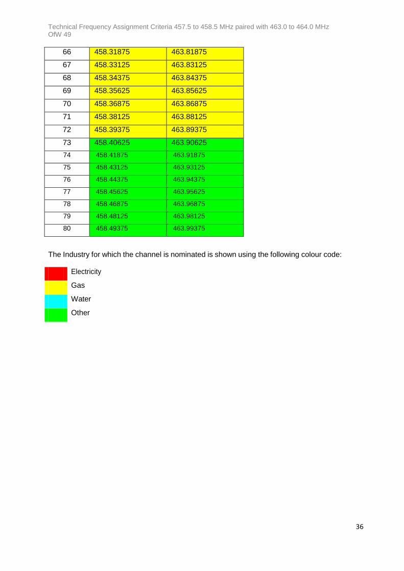
The following table shows the transmit frequencies for the scanning telemetry and telecontrol radio services operating in the band 457·5 to 464·0 MHz.
Channels Scanner
Outstations
1 457.50625 463.00625
2 457.51875 463.01875
3 457.53125 463.03125
4 457.54375 463.04375
5 457.55625 463.05625
6 457.56875 463.06875
7 457.58125 463.08125
8 457.59375 463.09375
9 457.60625 463.10625
10 457.61875 463.11875
11 457.63125 463.13125
12 457.64375 463.14375
13 457.65625 463.15625
14 457.66875 463.16875
15 457.68125 463.18125
16 457.69375 463.19375
17 457.70625 463.20625
18 457.71875 463.21875
19 457.73125 463.23125
20 457.74375 463.24375
21 457.75625 463.25625
22 457.76875 463.26875
23 457.78125 463.28125
24 457.79375 463.29375
25 457.80625 463.30625
26 457.81875 463.31875
27 457.83125 463.33125
28 457.84375 463.34375
29 457.85625 463.35625

Technical Frequency Assignment Criteria 457.5 to 458.5 MHz paired with 463.0 to 464.0 MHz OfW 49
35
30 457.86875 463.36875
31 457.88125 463.38125
32 457.89375 463.39375
33 457.90625 463.40625
34 457.91875 463.41875
35 457.93125 463.43125
36 457.94375 463.44375
37 457.95625 463.45625
38 457.96875 463.46875
39 457.98125 463.48125
40 458.99375 463.49375
41 458.00625 463.50625
42 458.01875 463.51875
43 458.03125 463.53125
44 458.04375 463.54375
45 458.05625 463.55625
46 458.06875 463.56875
47 458.08125 463.58125
48 458.09375 463.59375
49 458.10625 463.60625
50 458.11875 463.61875
51 458.13125 463.63125
52 458.14375 463.64375
53 458.15625 463.65625
54 458.16875 463.66875
55 458.18125 463.68125
56 458.19375 463.69375
57 458.20625 463.70625
58 458.21875 463.71875
59 458.23125 463.73125
60 458.24375 463.74375
61 458.25625 463.75625
62 458.26875 463.76875
63 458.28125 463.78125
64 458.29375 463.79375
65 458.30625 463.80625
Technical Frequency Assignment Criteria 457.5 to 458.5 MHz paired with 463.0 to 464.0 MHz OfW 49
36
66 458.31875 463.81875
67 458.33125 463.83125
68 458.34375 463.84375
69 458.35625 463.85625
70 458.36875 463.86875
71 458.38125 463.88125
72 458.39375 463.89375
73 458.40625 463.90625
74 458.41875 463.91875
75 458.43125 463.93125
76 458.44375 463.94375
77 458.45625 463.95625
78 458.46875 463.96875
79 458.48125 463.98125
80 458.49375 463.99375
The Industry for which the channel is nominated is shown using the following colour code:
Electricity
Gas
Water
Other

Technical Frequency Assignment Criteria 457.5 to 458.5 MHz paired with 463.0 to 464.0 MHz OfW 49
37
Annex B: Adaptable Cellular Plan Channel Sets
Cell Gas Electricity Water
Ch. 1 Ch. 2 Ch. 1 Ch. 2 Ch. 1 Ch. 2
A T57 T59 T3 T12 T44 T47
B T69 T65 T32 T6 T21 T36
C T48 T50 T29 T40 T31 T56
D T49 T51 T13 T24 T14 T16
E T64 T66 T27 T7 T30 T37
F T60 T62 T41 T25 T35 T45
G T70 T72 T10 T11 T19 T17
H T61 T63 T9 T34 T38 T46
J T52 T54 T23 T28 T5 T15
K T67 T58 T2 T33 T1 T39
L T68 T71 T8 T26 T30 T43
M T53 T55 T4 T42 T18 T22

Technical Frequency Assignment Criteria 457.5 to 458.5 MHz paired with 463.0 to 464.0 MHz OfW 49
38
Annex C: Adaptable Channel Plan Non-Adjacent Cell Channel Look-Up Table for the Electricity Industry
Home Cell
Home Cell Channels
First Tier Non- Adjacent Cells
First Tier Channels
Second Tier Non-Adjacent
Cells
Second Tier Channels
A T3 B T32 E T27
T12 T6 T7
C T29 H T9
T40 T34
M T4
T42
B T32 A T3 G T10
T6 T12 T11
C T29 F T41
T40 T25
L T8
T26
C T29 A T3 D T13
T40 T12 T24
B T32 J T23
T6 T28
K T2
T33
D T13 E T27 C T29
T24 T7 T40
F T41 J T23
T25 T28
K T2
T33
E T27 D T13 A T3
T7 T24 T12
F T41 H T9
T25 T34
M T4
T42
F T41 D T13 B T32
T25 T24 T6
E T27 G T10
T7 T11
Technical Frequency Assignment Criteria 457.5 to 458.5 MHz paired with 463.0 to 464.0 MHz OfW 49
39
L T8
T26
G T10 H T9 B T32
T11 T34 T6
J T23 F T41
T28 T25
L T8
T26
H T9 G T10 A T3
T34 T11 T12
J T23 E T27
T28 T7
M T4
T42
J T23 G T10 C T29
T28 T11 T40
H T9 D T13
T34 T24
K T2
T33
K T2 L T8 C T29
T33 T26 T40
M T4 D T13
T42 T24
J T23
T28
L T8 K T2 B T32
T26 T33 T6
M T4 F T41
T42 T25
G T10
T11
M T4 K T2 A T3
T42 T33 T12
L T8 E T27
T26 T7
H T9
T34

Technical Frequency Assignment Criteria 457.5 to 458.5 MHz paired with 463.0 to 464.0 MHz OfW 49
40
Annex D: Adaptable Channel Plan Non-Adjacent Cell Channel Look-Up Table for the Water Industry
Home Cell
Home Cell Channels
First Tier Non- Adjacent Cells
First Tier Channels
Second Tier Non-Adjacent
Cells
Second Tier Channels
A T44 B T21 E T30
T47 T36 T37
C T31 H T38
T56 T46
M T18
T22
B T21 A T44 G T19
T36 T47 T17
C T31 F T35
T56 T45
L T30
T43
C T31 A T44 D T14
T56 T47 T16
B T21 J T5
T36 T15
K T1
T39
D T14 E T30 C T31
T16 T37 T56
F T35 J T5
T45 T15
K T1
T39
E T30 D T14 A T44
T37 T16 T47
F T35 H T38
T45 T46
M T18
T22
F T35 D T14 B T21
T45 T16 T36
E T30 G T19
T37 T17

Technical Frequency Assignment Criteria 457.5 to 458.5 MHz paired with 463.0 to 464.0 MHz OfW 49
41
L T30
T43
G T19 H T38 B T21
T17 T46 T36
J T5 F T35
T15 T45
L T30
T43
H T38 G T19 A T44
T46 T17 T47
J T5 E T30
T15 T37
M T18
T22
J T5 G T19 C T31
T15 T17 T56
H T38 D T14
T46 T16
K T1
T39
K T1 L T30 C T31
T39 T43 T56
M T18 D T14
T22 T16
J T5
T15
L T30 K T1 B T21
T43 T39 T36
M T18 F T35
T22 T45
G T19
T17
M T18 K T1 A T44
T22 T39 T47
L T30 E T30
T43 T37
H T38
T46

Technical Frequency Assignment Criteria 457.5 to 458.5 MHz paired with 463.0 to 464.0 MHz OfW 49
42
Annex E: Adaptable Channel Plan Non-Adjacent Cell Channel Look-Up Table for the Gas Industry
Home Cell
Home Cell Channels
First Tier Non- Adjacent Cells
First Tier Channels
Second Tier Non-Adjacent
Cells
Second Tier Channels
A T57 B T69 E T64
T59 T65 T66
C T48 H T61
T50 T63
M T53
T55
B T69 A T57 G T70
T65 T59 T72
C T48 F T60
T50 T62
L T68
T71
C T48 A T57 D T49
T50 T59 T51
B T69 J T52
T65 T54
K T67
T58
D T49 E T64 C T48
T51 T66 T50
F T60 J T52
T62 T54
K T67
T58
E T64 D T49 A T57
T66 T51 T59
F T60 H T61
T62 T63
M T53
T55
F T60 D T49 B T69
T62 T51 T65
E T64 G T70
T66 T72
L T68

Technical Frequency Assignment Criteria 457.5 to 458.5 MHz paired with 463.0 to 464.0 MHz OfW 49
43
T71
G T70 H T61 B T69
T72 T63 T65
J T52 F T60
T54 T62
L T68
T71
H T61 G T70 A T57
T63 T72 T59
J T52 E T64
T54 T66
M T53
T55
J T52 G T70 C T48
T54 T72 T50
H T61 D T49
T63 T51
K T67
T58
K T67 L T68 C T48
T58 T71 T50
M T53 D T49
T55 T51
J T52
T54
L T68 K T67 B T69
T71 T58 T65
M T53 F T60
T55 T62
G T70
T72
M T53 K T67 A T57
T55 T58 T59
L T68 E T64
T71 T66
H T61
T63

Technical Frequency Assignment Criteria 457.5 to 458.5 MHz paired with 463.0 to 464.0 MHz OfW 49
44
Annex F: Adaptable Cellular Plan Cell Centre National and Irish Grid Reference Co-Ordinates
Cluster
/Cell
NGR Cluster
/Cell
NGR Cluster
/Cell
NGR
1A XW834750 5A SR834250 9A SM834750
1B SW401500 5B SM401000 9B SG401500
1C SX268500 5C SN268000 9C SH268500
1D SW618875 5D SM618375 9D SG618875
1E SX484875 5E SN484375 9E SH484875
1F SX051125 5F SS051625 9F SH051125
1G SX051875 5G SN051375 9G SH051875
1H SX484125 5H SS484625 9H SH484125
1J SW618125 5J SR618625 9J SG618125
1K XX268750 5K SS268250 9K SN268750
1L SX701500 5L SN701000 9L SH701500
1M SW834500 5M SM834000 9M SG834500
2A XZ433750 6A SU433250 10A SP433750
2B SZ000500 6B SP000000 10B SK000500
2C SZ866500 6C SP866000 10C SK866500
2D SZ216875 6D SP216375 10D SK216875
2E TV082875 6E TL082375 10E TF082875
2F SZ649125 6F SU649625 10F SK649125
2G SZ649875 6G SP649375 10G SK649875
2H TV082125 6H TQ082625 10H TF082125
2J SZ216125 6J SU216625 10J SK216125
2K XZ866750 6K SU866250 10K SP866750
2L TV299500 6L TL299000 10L TF299500
2M SZ433500 6M SP433000 10M SK433500
3A SY134500 7A SO134000 11A SJ134500
3B SS701250 7B SN701750 11B SC701250
3C ST567250 7C SO567750 11C SD567250
3D SS917625 7D SH917125 11D SC917625
3E ST783625 7E SJ783125 11E SD783625
3F SY350875 7F SO350375 11F SJ350375
3G ST350625 7G SJ350125 11G SD350625
3H SY783875 7H SO783375 11H SJ783875
3J SX917875 7J SN917375 11J SH917875
3K SY567500 7K SO567000 11K SJ567500
3L SU000250 7L SP000750 11L SE000250

Technical Frequency Assignment Criteria 457.5 to 458.5 MHz paired with 463.0 to 464.0 MHz OfW 49
45
3M ST134250 7M SO134750 11M SD134250
4A TV732500 8A TL732000 12A TF732500
4B TQ299250 8B TL299750 12B TA299250
4C TR165250 8C TM165750 12C TB165250
4D TQ515625 8D TF515125 12D TA515625
4E TR381625 8E TG381125 12E TB381625
4F TV948875 8F TL948375 12F TF948875
4G TQ948625 8G TF948125 12G TA948625
4H TW381875 8H TM381375 12H TG381875
4J TV515875 8J TL515375 12J TF5I1875
4K TW165500 8K TM165000 12K TG165500
4L TR598250 8L TM598750 12L TB598250
4M TQ732250 8M TL327750 12M TA732250
13A SB834250 17A NZ433750 21A NJ134000
13B NW401000 17B NU000500 21B NB701750
13C NX268000 17C NU866500 12C NJ567750
13D NW618375 17D NU216875 21D NC917125
13E NX484375 17E MQ082875 21E ND783125
13F SC051625 17F NU649125 21F NJ350375
13G NX051375 17G NU649875 21G ND350125
13H SC484625 17H MQ082125 21H NJ783375
13J SB618625 17J NU216125 21J NH917375
13K SC268250 17K NZ866750 21K NJ567000
13L NX701000 17L MQ299500 21L NK000750
13M NW834000 17M NU433500 21M NJ134750
14A SE6433250 18A NT134500 22A NB834750
14B NZ000000 18B NN701250 22B NB401500
14C NZ866000 18C NO567250 22C NC268500
14D NZ216375 18D NN917625 22D NB618875
14E MV082375 18E NO783625 22E NC484875
14F SE649625 18F NT350875 22F NC051125
14G NZ649375 18G NO350625 22G NC051875
14H TA082625 18H NT783875 22H NC484125
14J SE216625 18J NS917875 22J NB618125
14K SE866250 18K NT567500 22K NH268750
14L MV299000 18L NP000250 22L NC701500
14M NZ433000 18M NO134250 22M NB834500
15A NY134000 19A NM834250 23A ND134500
15B NX701750 19B NG401000 23B HC701250

Technical Frequency Assignment Criteria 457.5 to 458.5 MHz paired with 463.0 to 464.0 MHz OfW 49
46
15C NY567750 19C NH268000 23C HD567250
15D NS917125 19D NG618375 23D HC917625
15E NT783125 19E NH484375 23E HD783625
15F NY350375 19F NN051625 23F ND350875
15G NT350125 19G NH051375 23G HD350625
15H NY783375 19H NN484625 23H ND783875
15J NX917375 19J NM618625 23J NC917875
15K NY567000 19K NN268250 23K ND567500
15L NZ000750 19L NH701000 23L HE000250
15M NY134750 19M NG834000 23M HD134250
16A NW834750 20A NP433250 24E NW184375
16B NR401500 20B NK000000 27C NL066250
16C NS268500 20C NK866000 27E NM183265
16D NR618875 20D NK216375 27G NL049625
16E NS484875 20E MF082375 27H NR183875
16F NS051125 20F NP649625 27L NM400250
16G NS051875 20G NK649375 28A NF033000
16H NS484125 20H ML082625 28C NF067752
16J NR618125 20J NP216625 28E NB184128
16K NX268750 20K NP866250 28F NF051375
16L NS701500 20L MF299000 28H NG184375
16M NR834500 20M NK433000 28K NF067000
28L NG401752
13B J302441 26C C807150 26H J055795
13D J486833 26D C129467 26J H193721
25L H003329 26E C991542 26K H871403
26A H440366 26F H624758 26L D238187
26B B945075 26G C560504 26M C376112

Technical Frequency Assignment Criteria 457.5 to 458.5 MHz paired with 463.0 to 464.0 MHz OfW 49
47
Document History
Version Date Changes
1.0 Sept 2004 Rebranded to Ofcom Style
2.0 Jan 2015 Updated to incorporate VNS2111 and RA386
2.1 Aug 2015 Editorial corrections
3.0 May 2017 Removal of interleaved channel options and update to allow for different digital modulations.
Riverside House 2a Southwark Bridge Road London SE1 9HA Telephone: 020 7981 3131 or 0300 123 1000 Fax: 020 7981 3235 Email: [email protected] Website: http://www.ofcom.org.uk/radiocomms/