Fluid Solid Interaction (FSI) analysis of 24 Lehman rear wing profile in high speed

OMAE 2012 -83472: Offshore Platform Fluid Structure Interaction (FSI) Simulation
Offshore Platform Fluid Structure Interaction (FSI) Simulation
Ali Marzaban, CD-adapcoMurthy Lakshmiraju, CD-adapcoNigel Richardson, CD-adapco
Mike Henneke, CD-adapco
Guangyu Wu, ChevronPedro M. Vargas, Chevron
Owen Oakley, Chevron
August 13, 2013 1

OMAE 2012 -83472: Offshore Platform Fluid Structure Interaction (FSI) Simulation
Introduction
• The main objective of this study was to predict the permanent deformation of an offshore platform from a large wave incident during a storm using Fluid Structure Interaction (FSI).
• A representative sub-modeled 1/8th section of the offshore oil platform that was deformed permanently during a hurricane is demonstrated.
• Study was divided into three phases to progressively develop a FSI methodology to predict the permanent deformation of the platform :
– Phase 1: Static and transient dynamic structural investigation was conducted on a sub-model section of the platform to predict potential wave energy required to cause the field observed deformation (around 40 cm deformation was reported on one of the plate girders).
• ABAQUS 6.11 was used for Finite Element Analysis (FEA).– Phase 2: Hurricane waves were simulated using Computational Fluid Dynamics
(CFD) to determine wave characteristics required to induce the magnitude of pressure needed to observe same deformation on a structure (Based on Phase 1).
• STAR-CCM+ 6.06 was used for CFD analysis– Phase 3: One-way coupled simulations were modeled to study impact analysis on the
structure due to wave pressure.
2August 13, 2013
OMAE 2012 -83472: Offshore Platform Fluid Structure Interaction (FSI) Simulation
Phase1 – Finite Element Analysis
3
• A 3D finite element model of an offshore platform was generated from Chevron provided 2D drawings.
• The model was investigated for a single wave impact event using ABAQUS 6.11 to study the permanent plastic deformation.
• The model has been analyzed using both static and transient dynamic (implicit) approach.
• Varying pressure loads were applied in the static cases to validate recorded field data deformation (40 cm on one of the plate girders).
• Pressures were applied at different periods during the implicit analysis studies.
August 13, 2013

OMAE 2012 -83472: Offshore Platform Fluid Structure Interaction (FSI) Simulation
Phase2 – Computational Fluid Dynamics
• A uni-directional wave field was generated based on 60 individual wave components (provided by Chevron) using a Fortran based user sub-routine code.
• 2D simulations were performed without the platform to determine the position of the peak wave occurrence to place the structure.
• 2D simulations also helped in estimating the mesh size and time step for coupling fluid-structure interaction phase.
• Platform was situated such that maximum energy would be imparted on the structure.
4August 13, 2013

OMAE 2012 -83472: Offshore Platform Fluid Structure Interaction (FSI) Simulation
Phase3 – One-way Coupled Fluid Structure Interaction
• One-way coupling scheme: Fluid imparted pressures on the structure will be transferred to the FE model but the response of the structure to the fluid will be neglected.
– Structure is treated as a rigid body in the CFD model
• One-way coupling analysis was performed to predict the observed deformation on plate girders using STAR-CCM+ and ABAQUS co-simulation.
5August 13, 2013

OMAE 2012 -83472: Offshore Platform Fluid Structure Interaction (FSI) Simulation
Laser Scan Measurement of Plate Girders
6August 13, 2013

OMAE 2012 -83472: Offshore Platform Fluid Structure Interaction (FSI) Simulation
Phase 1
7August 13, 2013

OMAE 2012 -83472: Offshore Platform Fluid Structure Interaction (FSI) Simulation
Modeling Assumption and Material Properties
8
• The 3D FEA model was generated from 2D drawings provided by Chevron.
• C3D20R elements were used to model all solid parts.
• Local connection details (bolts and welds) were not considered. All joint were considered to be infinitely stiff.
• Elastic-plastic material properties was used for plate girders.
August 13, 2013
For plate girders A588 typical material properties was used: •Initial Elastic Modulus: 200 GPa•Poisson’s ratio: 0.3•Density : 7830 kg/m3
•Yield Stress: 379.2 MPa•Ultimate Stress: 530.9 MPa
OMAE 2012 -83472: Offshore Platform Fluid Structure Interaction (FSI) Simulation
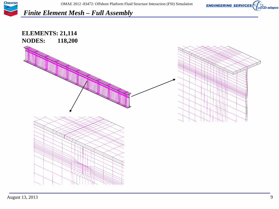
Finite Element Mesh – Full Assembly
9August 13, 2013
ELEMENTS: 21,114NODES: 118,200

OMAE 2012 -83472: Offshore Platform Fluid Structure Interaction (FSI) Simulation
10
Applied Boundary Conditions
August 13, 2013
• Gravity is applied in negative z-direction.• Uniform pressure distribution was applied to the plate girder in positive x-direction.
Fixed in all DOF
Fixed in x-direction
Applied pressure
Uniform Pressure in x-direction
OMAE 2012 -83472: Offshore Platform Fluid Structure Interaction (FSI) Simulation
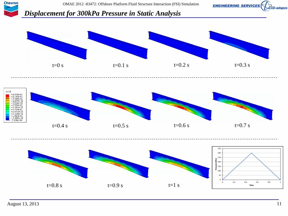
Displacement for 300kPa Pressure in Static Analysis
11August 13, 2013
t=0 s t=0.1 s t=0.2 s t=0.3 s
t=0.4 s t=0.5 s t=0.6 s t=0.7 s
t=0.8 s t=0.9 s t=1 s

OMAE 2012 -83472: Offshore Platform Fluid Structure Interaction (FSI) Simulation
Plastic Strain in Static Analysis
12August 13, 2013

OMAE 2012 -83472: Offshore Platform Fluid Structure Interaction (FSI) Simulation
Static Analysis
13August 13, 2013
• In the static analysis, the load was applied as a uniform pressure.• Five different load cases with different maximum pressure of (100, 150, 200, 250 and
300kPa) was considered.• The pressure was applied as a ramp from zero to max from t=0 to t=0.5s. Then the
pressure was released as a ramp from the max pressure to zero from t=0.5s to t=1s.
Displacement of node A in x-direction with different pressures Deformed location of node A in x-direction with different pressures
A
43cm deflectionPressure=277kPa
OMAE 2012 -83472: Offshore Platform Fluid Structure Interaction (FSI) Simulation
Implicit Analysis
14August 13, 2013
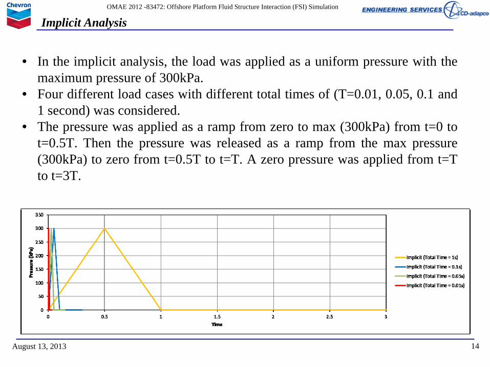
• In the implicit analysis, the load was applied as a uniform pressure with the maximum pressure of 300kPa.
• Four different load cases with different total times of (T=0.01, 0.05, 0.1 and 1 second) was considered.
• The pressure was applied as a ramp from zero to max (300kPa) from t=0 to t=0.5T. Then the pressure was released as a ramp from the max pressure (300kPa) to zero from t=0.5T to t=T. A zero pressure was applied from t=T to t=3T.

OMAE 2012 -83472: Offshore Platform Fluid Structure Interaction (FSI) Simulation
Displacement in x-direction for Different Times in Implicit Analysis
15August 13, 2013
Displacement of node A in x-directionwith different Frequency for 300kPa
A
0.5T T 1.5T 2T 2.5T 3T
0.5T T 1.5T 2T 2.5T 3T
Applied Force vs Time

OMAE 2012 -83472: Offshore Platform Fluid Structure Interaction (FSI) Simulation
Required Pressure for 43 cm Displacement
16August 13, 2013
Total Time (s) Pressure (kPa)0.05 4150.1 3220.5 2731 2705 275
Static 277

OMAE 2012 -83472: Offshore Platform Fluid Structure Interaction (FSI) Simulation
Phase 2
17August 13, 2013
OMAE 2012 -83472: Offshore Platform Fluid Structure Interaction (FSI) Simulation
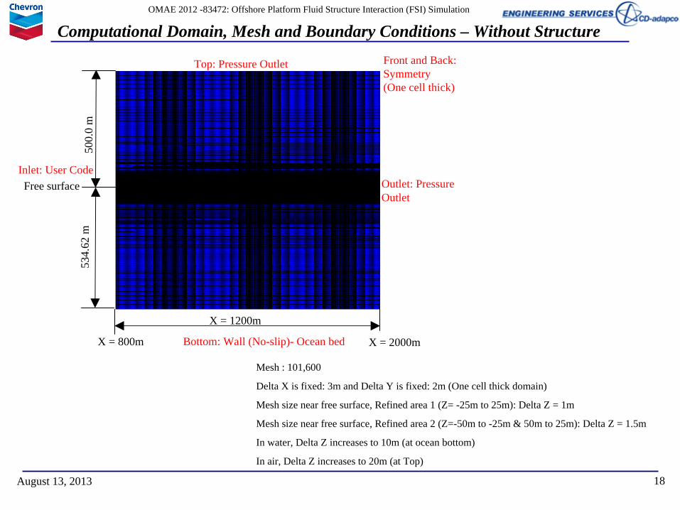
Computational Domain, Mesh and Boundary Conditions – Without Structure
18August 13, 2013
X = 1200m
Free surface
534.
62 m
500.
0 m
Top: Pressure Outlet
Inlet: User Code
Bottom: Wall (No-slip)- Ocean bed
Outlet: Pressure Outlet
X = 800m X = 2000m
Front and Back:Symmetry (One cell thick)
Mesh : 101,600
Delta X is fixed: 3m and Delta Y is fixed: 2m (One cell thick domain)
Mesh size near free surface, Refined area 1 (Z= -25m to 25m): Delta Z = 1m
Mesh size near free surface, Refined area 2 (Z=-50m to -25m & 50m to 25m): Delta Z = 1.5m
In water, Delta Z increases to 10m (at ocean bottom)
In air, Delta Z increases to 20m (at Top)

OMAE 2012 -83472: Offshore Platform Fluid Structure Interaction (FSI) Simulation
CFD Methodology• Physical Models used:
– Three dimensional– Implicit unsteady– Gravity– Multiphase mixture– Eulerian multiphase
• Water: Constant density– Density: 997.561 Kg/m3 and Dynamic viscosity: 8.887E-4 Pa-s
• Air: Constant density– Density: 1.18415 Kg/m3 and Dynamic viscosity: 1.85508E-5 Pa-s
– Volume of Fluid – VOF waves - Flat water condition (for generating mean free surface)
– Turbulence:– SST (Menter) K-Omega turbulence model with High y+ Wall treatment
– Wave Damping• Imposed from 400m from outlet
19August 13, 2013

OMAE 2012 -83472: Offshore Platform Fluid Structure Interaction (FSI) Simulation
Wave specifications
• Water depth: 1754 ft (534.6m)• Peak wave period: 14.8s• Zero crossing (Mean) wave period: 10.2s• Maximum wave height: 74 ft ±1.5 ft (22.55m ± 0.457m)• Significant wave height: 43.3 ft (13.19m)• Surface current (above – 200ft) velocity: 2.1 knots (1.08m/s)• Static wind speed: 85 knots (43.72 m/s)
– Direction of surface current and wind speeds are unknown– Assumption: static current and wave speed direction is same as the wave advancing
direction.• Height of the lower deck to free surface: 56 ft (17.07 m)
• Wave properties: (provided by Chevron)
– Superposition of 60 waves– Highest crest is 16.92m at 1325.6m and 166.0 s– Velocity, height, volume fraction: calculated on a point-by-point basis from given
data using a FORTRAN subroutine20August 13, 2013

OMAE 2012 -83472: Offshore Platform Fluid Structure Interaction (FSI) Simulation
CFD Methodology
• Initial Conditions:– Pressure: Hydrostatic Pressure of mean free surface– Velocity: User code
• Used single wave velocity field at t=130s for wave– Volume fractions:
• Air: 0.0• Water: User code
21August 13, 2013
Wave Height at 130.0s From Fortran (Initial condition)
OMAE 2012 -83472: Offshore Platform Fluid Structure Interaction (FSI) Simulation
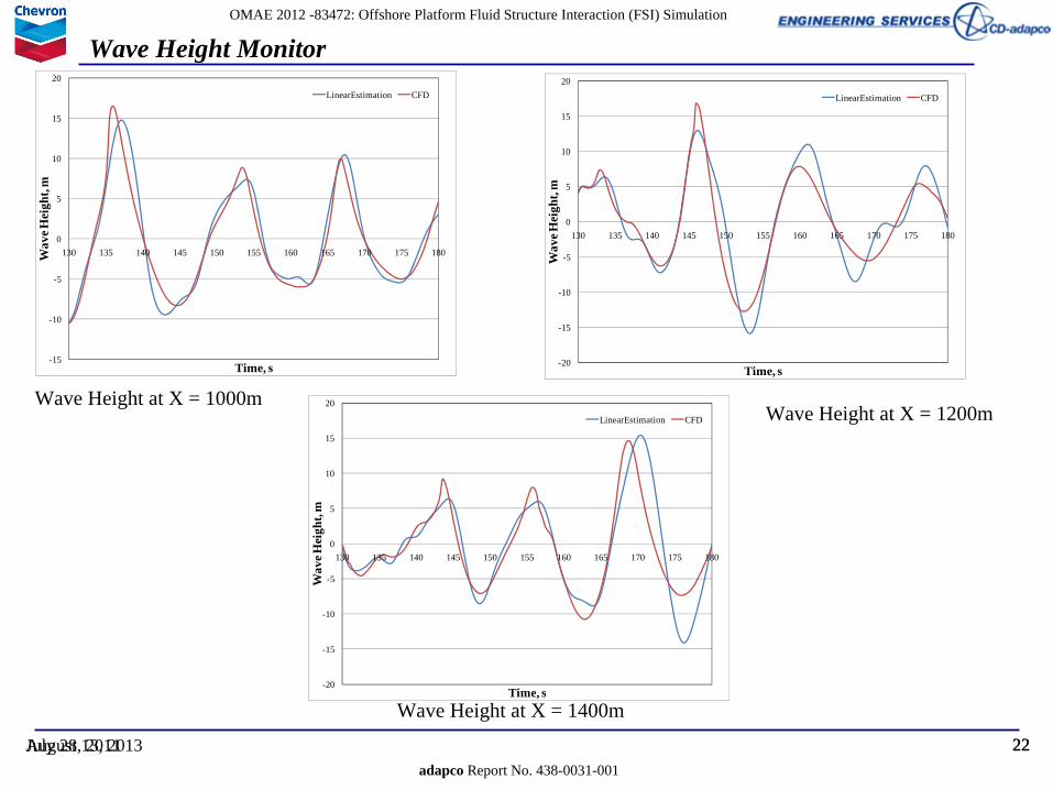
Wave Height Monitor
22adapco Report No. 438-0031-001
July 28, 2011
-15
-10
-5
0
5
10
15
20
130 135 140 145 150 155 160 165 170 175 180Wav
e Hei
ght,
m
Time, s
LinearEstimation CFD
August 13, 2013 22
-20
-15
-10
-5
0
5
10
15
20
130 135 140 145 150 155 160 165 170 175 180
Wav
e Hei
ght,
m
Time, s
LinearEstimation CFD
-20
-15
-10
-5
0
5
10
15
20
130 135 140 145 150 155 160 165 170 175 180
Wav
e Hei
ght,
m
Time, s
LinearEstimation CFD
Wave Height at X = 1000mWave Height at X = 1200m
Wave Height at X = 1400m

OMAE 2012 -83472: Offshore Platform Fluid Structure Interaction (FSI) Simulation
Transparent view
Computational Domain and Boundary Conditions
23August 13, 2013
Inlet: User Code
Outlet: Pressure OutletTop: Wall (Slip condition)
Bottom: Wall (No-slip)- Ocean bed
Sides: Symmetry
X=800m X=1150m X=2000m
Z=-534.62m
Z= 300m
Z= 0m
X=1600m
Damping Zone
Platform:Length along X: 15.7mDepth along Y: 16.1mHeight along Z: 1.56mI-Beam 3 at X=1150mBottom of Structure = 17m
X: Wave Advancing DirectionZ: Normal to Wave Advancing Direction – Along Gravity
Y= -150m Y= 0m Y= 150m
Z= 17m
Platform Model in CFD Analysis

OMAE 2012 -83472: Offshore Platform Fluid Structure Interaction (FSI) Simulation
Mesh
24August 13, 2013
Mesh : 7,154,319
Mesh size near free surface, Refined area (Z= -15m to 25m): Delta X & Delta Y = 2.44m, Delta Z = 0.609m
Away from free surface: Delta X = 19.5, Delta Y = 9.75m, Delta Z = 19.5m
Plane Y=0m Plane X=1150m

OMAE 2012 -83472: Offshore Platform Fluid Structure Interaction (FSI) Simulation
Mesh – Plane Y=0m
25August 13, 2013

OMAE 2012 -83472: Offshore Platform Fluid Structure Interaction (FSI) Simulation
Surface Elevation
26August 13, 2013
Wave history plots and surface elevation plot indicates free surface in 3D model is close to that of the free surface from 2D model

OMAE 2012 -83472: Offshore Platform Fluid Structure Interaction (FSI) Simulation
Phase 3
27August 13, 2013

OMAE 2012 -83472: Offshore Platform Fluid Structure Interaction (FSI) Simulation
3D- Domain
28August 13, 2013
X=800m X=1150m X=2000m Y= -150m Y= 0m Y= 150m
Z=-534.62m
Z= 300m
Z= 0m
X=1600m
Z= 17m
Damping Zone
Model:I-Beam 3 at X=1150mBottom of Structure = 13m

OMAE 2012 -83472: Offshore Platform Fluid Structure Interaction (FSI) Simulation
Finite Element Mesh – Full Assembly
29August 13, 2013
269,361 linear hexahedral elements of type C3D8RTotal Elements: 269,361Total Nodes: 408,231C3D8R: 8-node linear brick, reduced integration with hourglass control
Top Plate
* The connectiondetails has beenignored. All jointwere considered tobe infinitely stiff.

OMAE 2012 -83472: Offshore Platform Fluid Structure Interaction (FSI) Simulation
Applied Boundary Condition
30August 13, 2013
Fixed inZ-direction (Supports)
Fixed inX ,Y and Z Rot
Fixed in X, Y-direction (Connected to rest of the deck)
Fixed in X, Y-direction
* Top deck was vertically restrained

OMAE 2012 -83472: Offshore Platform Fluid Structure Interaction (FSI) Simulation
Displacement Magnitude
31August 13, 2013
47cm
17cm

OMAE 2012 -83472: Offshore Platform Fluid Structure Interaction (FSI) Simulation
Comparison of Deformation of Plate Girders with Filed Data
32August 13, 2013
0
5
10
15
20
25
30
35
40
45
50
0 2 4 6 8 10 12
Dis
plac
emen
t in
x-di
rect
ion
(cm
)
Lentgh of plate girder (m)
Member A - Field Data
Member A - Analysis Results
Member B - Field Data
Member B - Analysis Results
Length = 12.0m
Length =0.0m

OMAE 2012 -83472: Offshore Platform Fluid Structure Interaction (FSI) Simulation
Conclusions
• A One-way coupled Fluid Structure Interaction was investigated for predicting permanent deformation on an offshore platform from a large wave incident during a storm.
• Results are comparable to the actual field measurements
• The deformation on plate girders can also be due to several wave impacts during the hurricane and the deformation magnitude of the plate girders will be superimposed due to these multiple impacts
• Results suggest that sufficiently accurate solution for the design of offshore platforms can be obtained with this methodology.
33August 13, 2013