Offshore Blades foresighting final - Evaluations Online
28
© ITI Scotland Ltd 2008 (except where indicated) FORESIGHTING REPORT Advanced Blades for Offshore Wind Addressing technologies required to drive down the cost of wind energy offshore For Members Only 25 th March 2008 V1.0 Disclaimer The information contained in this document is believed to be accurate, but no representation or warranty, express or implied, is made by ITI Scotland Limited as to the completeness, accuracy or fairness of any information contained in this document. No responsibility can be accepted for the outcome of any decision or action that is made using any of the information, data or recommendations that may be contained within this document.
Transcript of Offshore Blades foresighting final - Evaluations Online
© ITI Scotland Ltd 2008 (except where indicated)
FORESIGHTING REPORT Advanced Blades for Offshore Wind
Addressing technologies required to drive down the cost of wind energy offshore
For Members Only
25th March 2008
V1.0
Disclaimer The information contained in this document is believed to be accurate, but no representation or warranty, express or implied, is made by ITI Scotland Limited as to the completeness, accuracy or fairness of any information contained in this document. No responsibility can be accepted for the outcome of any decision or action that is made using any of the information, data or recommendations that may be contained within this document.

© ITI Scotland Ltd 2008 (except where indicated) Page 1
BLADES FOR OFFSHORE WIND TURBINES Electricity Generation from Offshore Wind Various factors including climate change, resource depletion and energy security have caused the developed nations to set extremely ambitious electricity generation targets for renewable sources. In 2003, the European Wind Energy Association (EWEA) estimated that the EU member states will have installed 180 GW of wind capacity by 2020, 70 GW of which they predicted to be offshore. Similarly, studies commissioned by ITI Energy indicate a cumulative global installed capacity of over 250GW by 2015 (see Figure 1).
0
5000
10000
15000
20000
25000
30000
35000
1999 2000 2001 2002 2003 2004 2005 2006 2007 2008 2009 2010 2011 2012 2013 2014 2015
Installed, MW
0
50000
100000
150000
200000
250000
300000
Cumulative, MW
New Installed Capacity Cumulative Installed Capacity
Source of data: BTM Consult historic data and Digital Composites SaRL projections Figure 1: Global New & Cumulative Capacity (MW) The global wind market is currently undergoing significant growth in new installed capacity. This growth phase is shifting the industry from a 8,000 MW per year plateau (through the period 2001-2004) to a new plateau in the region of 18,000 MW from 2009-2010 onwards. Onshore wind dominates the overall wind energy sector at present, but there are serious concerns about the quality of the wind regime and resultant energy yield, noise levels and visual pollution. The annual average wind speeds are higher offshore than onshore (see Figure 2), and the inherent low surface roughness leads to minimal levels of wind shear. Consequently

© ITI Scotland Ltd 2008 (except where indicated) Page 2
a new generation of larger, more powerful wind turbines are being developed to take advantage of this favourable resource.
0
100
200
300
400
500
600
700
800
900
0 1 2 3 4 5 6 7 8 9 10 11 12 13 14 15 16 17 18 19 20 21 22 23 24 25
Wind Speed, m/s
Duration, Hours Onshore, US, Energy Yield: 12.6 GWhrs, CF: 29%Offshore, Denmark, Energy Yield: 21.9 GWhrs, CF: 50%
Source of data: ITI Energy Analysis Figure 2: Annual Wind Speed Distribution Data Current offshore wind turbines can be summarised as having the following configuration; upwind, three-bladed rotor with rigid hub, full-span pitch control and full variable speed operation. The large offshore turbines in development will almost certainly conform to this configuration, be rated between 5 and 10 MW, and have very large rotor diameters of up to 180 metres. The diagram below shows the predicted trend in wind turbine ratings over time. The general trend to larger capacities is evident.
0%
10%
20%
30%
40%
50%
60%
70%
80%
90%
100%
2002 2003 2004 2005 2006 2007 2008 2009 2010 2011 2012 2013 2014 2015
< 750 KW 750 - 1,500 KW 1,500 - 2,500 KW > 2500 KW Source of data: BTM Consult historic data and Digital Composites SaRL projections �
Figure 3: Increasing Turbine Size, 2002-2015

© ITI Scotland Ltd 2008 (except where indicated) Page 3
Despite previous forecasts of large increases in offshore capacity, actual projects have materialised more slowly than many developers expected. So far, the sector has yet to prove a major growth driver for wind developers and independent power projects (IPPs). At present, offshore wind accounts for approximately 1% of global installed wind capacity. Banks have become relatively comfortable with the risks associated with onshore wind projects, so competition amongst them has resulted in very narrow spreads on the project finance they provide. By contrast, banks and other providers of project finance view offshore wind as relatively untested and thus high risk. Few offshore wind farms to date have been built with true non-recourse debt. Thus they have tended to be developed by, or in conjunction with, companies large enough to take the debt onto their own balance sheets - typically large utilities or, implicitly, governments. It is reasonable to expect this to change as banks better understand the risk, however the initial spread on non-recourse debt can be expected to be significantly higher for offshore than for onshore wind projects.
0 500 1000 1500 2000 2500 3000 3500
EON
WPD
DONG
RWE / npower
Airtricity
Centrica
Vattenfall
Shell
AMEC
Scottish Power
Eurus
Evelop / Econcern
Essent
EnergieKontor
EDF
Warwick
Plambeck
RES
Prokon Nord
Eclipse
Capacity, MW Source of data: Developers and Emerging Energy Research Figure 4: Offshore Project pipelines by type of player It is important to note that there are some clear discrepancies between various offshore capacity forecasts. The EWEA targets suggest that 5GW of new European offshore wind will be required annually up to 2020 and LM have estimated that German Offshore capacity alone will reach 30 GW. At the lower end of the scale, various market studies indicate that the global offshore installation rate will not top 2GW in the next 10 years.
Utility
IPP
Developer
© ITI Scotland Ltd 2008 (except where indicated) Page 4
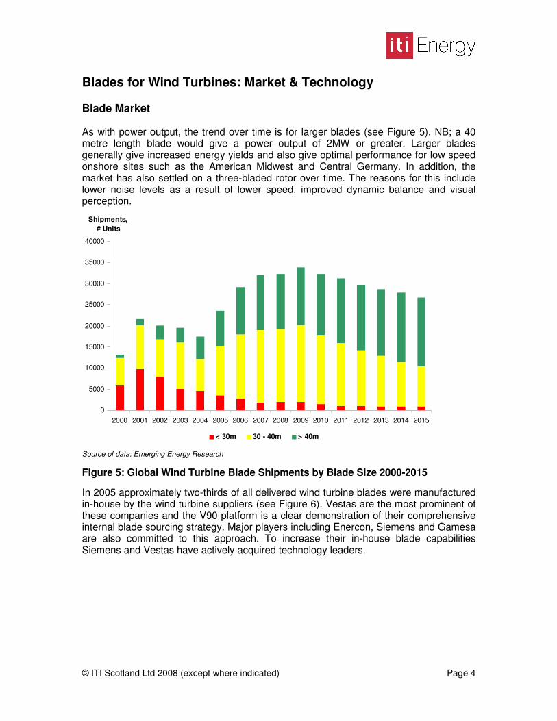
Blades for Wind Turbines: Market & Technology Blade Market As with power output, the trend over time is for larger blades (see Figure 5). NB; a 40 metre length blade would give a power output of 2MW or greater. Larger blades generally give increased energy yields and also give optimal performance for low speed onshore sites such as the American Midwest and Central Germany. In addition, the market has also settled on a three-bladed rotor over time. The reasons for this include lower noise levels as a result of lower speed, improved dynamic balance and visual perception. �
0
5000
10000
15000
20000
25000
30000
35000
40000
2000 2001 2002 2003 2004 2005 2006 2007 2008 2009 2010 2011 2012 2013 2014 2015
Shipments, # Units
< 30m 30 - 40m > 40m � Source of data: Emerging Energy Research Figure 5: Global Wind Turbine Blade Shipments by Blade Size 2000-2015 In 2005 approximately two-thirds of all delivered wind turbine blades were manufactured in-house by the wind turbine suppliers (see Figure 6). Vestas are the most prominent of these companies and the V90 platform is a clear demonstration of their comprehensive internal blade sourcing strategy. Major players including Enercon, Siemens and Gamesa are also committed to this approach. To increase their in-house blade capabilities Siemens and Vestas have actively acquired technology leaders.

© ITI Scotland Ltd 2008 (except where indicated) Page 5
Turbine Manufacturer Blade Supplier Vestas LM Glassfiber, Vestas GE Wind LM Glassfiber, A&R, Tecsis, MFG Mitsubishi Mitsubishi (Vientek) Gamesa Gamesa, LM Glassfiber Nordex Nordex, NOI, LM Glassfiber, Baoding HT Siemens Siemens, LM Glassfiber REpower LM Glassfiber, A&R Ecotecnia LM Glassfiber Enercon Enercon Suzlon Suzlon, LM Glassfiber Acciona Windpower LM Glassfiber Goldwind LM Glassfiber, Baoding HT
Vestas26%
Enercon13%
Gamesa8%Suzlon
6%
LM Glassfiber28%
Others6%
Nordex2%
Siemens4%
NOI3%
Euros1%
Mitsubishi3%
Source of data: Suppliers and Emerging Energy Research Figure 6: Blade Supply Relationships and Market Share Meanwhile, Denmark’s LM-Glassfiber, the single largest supplier, is an independent manufacturer serving almost all of the top turbine makers. LM has a clear business strategy, which includes a tendency to avoid the use of exotic materials and the location of its facilities close to major demand centres in Europe, Asia and the US. Though LM competes with a number of specialised blade manufacturers to a certain extent, the likes of NOI or Euros, appear to lack the scale and resources to become major players. As a proportion of overall development cost, blade costs are approximately 12% for onshore wind farms and 6.5% for offshore. This lower proportion is due to the significant increase in civil works, transport and installation costs when moving offshore. The potential size of the European offshore blades market is as high as £600 million per annum, based on EWEA targets and industry data. High performance offshore blades are likely to have a cost build-up as follows: 70% materials, 10% labour and 20% factory overhead.

© ITI Scotland Ltd 2008 (except where indicated) Page 6
Blade technology Blade Theory The blades are the energy capture components of the wind turbine and rely on the classical aerofoil principal where difference in fluid velocities between two surfaces leads to a pressure differential and a force known as aerodynamic lift. The motion of the blade is constrained in such a way that the lift force is translated to rotational movement for input to an electrical generator. The resultant power output of any given blade is fundamentally based upon the air density, swept area of the blade, velocity of the wind and a theoretical constant known as the Betz coefficient. Consequently there has been a historic trend towards larger and larger blades. Historically, blade length has increased by 10% annually and doubled approximately every seven years. In theory the mass of the blade should scale as a cube of the length. In reality the scaling exponent has been demonstrated to be lower. This may be explained by increased use of high performance fibres, improved resin qualities and innovative design. Blade Geometry The external shape of wind turbine blades varies from a lift generating aerofoil to a structural cylinder at its root. When viewed from above, the “plan-form” of a blade tapers outwards from the root to its maximum chord length (blade width) and then tapers inwards back to the tip (see Figure 7). The aerofoil section has a rounded leading edge and a sharp trailing edge.
Source of data: Sandia Report SAND2003-0723 Figure 7: Representative Large Blade Planform The transition from pure aerofoil to structural cylinder is smooth and there are a number of well understood aerofoil ‘families’. As well as variable cross section there is a twist angle of approximately 20 degrees along the blade’s longitudinal axis. At the root end, the blade must be terminated by a steel connector for attachment to a large hub casting.

© ITI Scotland Ltd 2008 (except where indicated) Page 7
Blade Structure Blade structure results from consideration of both the aerodynamics and the loading regimes, which can be broken into the following three forms:
• Gravity loading: cycles between tension and compression as the blade turns. The larger the blade, the greater this loading becomes
• Centrifugal loadings: increase and decrease as rotational speed varies. At very high tip speeds, centrifugal loadings may become a more serious design driver
• Aerodynamic loading: takes many forms including gust loading, tower shadowing and turbulent effects
These loadings are applied almost continuously over a 25 year service life and approximately 108 cycles. The main stresses tend to act along the longitudinal axis of the blade, therefore reinforcement fibres tend to run in this direction. The generic blade consists of a load-bearing spar, around which the two aerofoil shells are bonded. The structural spar is typically in the form of a tapered box section where large bending and compressive loads are transmitted through the spar caps and smaller shear loads are transmitted through the shear web(s). Blade Materials All large commercial blades can be defined as composite structures, i.e. they are a sandwich of directional fibres embedded in a polymer matrix, usually epoxy or polyester. Material choice is dependent on an acceptable balance of mechanical properties for the various loading modes, ease of manufacture and cost (see Table 1).
Property Glass Aramid Carbon Tensile Strength Good Good Excellent Compressive Strength Good Poor Excellent Flexural Strength Good Poor Excellent Impact Resistance Good Excellent Poor Density Poor Excellent Good Fatigue Resistance Poor Good Excellent Cost Excellent Poor Poor
Table 1: Material Comparison Matrix Glass fibre is the most commonly used reinforcement material and epoxy has largely replaced polyester as the preferred resin system. Manufacturers look to achieve the very best fibre to volume ratio with maximum resin infusion. In some very large blades, carbon fibre is used as reinforcement in the highly stressed spar cap region. The generic problem with sandwich constructions, as compared to monolithic materials, is that they are prone to delamination and failure at weak interfaces between materials with differing stiffness / strength properties.

© ITI Scotland Ltd 2008 (except where indicated) Page 8
Blade Manufacture Current blade manufacture is an incremental development of traditional boat building techniques. The current generic process of large blade manufacture can be described as follows:
• Large open mould prepared • Gelcoat (outer surface) sprayed into mould • Outer reinforcement is laid out in mould • Core materials are laid out • Inner reinforcement is laid out on top • Vacuum film is stretched over sandwich • Resin is drawn through the sandwich under vacuum • Vacuum film is removed • Structural spar installed • Adhesive applied to spar webs and shell edges • Shells are bonded together • Finishing process
This Vacuum Assisted Resin Transfer Moulding (VARTM) process is labour intensive, but achieves acceptable fibre volume fractions at an economic cost. Due in part to labour content, the quality of each blade is intrinsically variable and highly dependant on the skills of the workface. The Ideal Blade All offshore and onshore wind turbines are designed with the aim of reducing the Cost of Energy (COE). The Cost of Energy calculation is based on three key components, these being: Initial Capital Cost (ICC); Annual Energy Production (AEP); and Annual Operating Expenses (AOE). In order to achieve the minimum COE value for offshore wind, the idealised blade can be defined as having the following characteristics:
• Large swept area: increase energy capture in costly offshore locations • Minimal weight: decrease stresses in the system and increase ease of
installation • Optimum aerodynamic efficiency: increase the lift to drag ratio to a maximum
value • Maximum structural strength: resist fatigue and gravity loading • High speed operable: increase generator efficiency and reduce torque • Wind compliant: eliminate fatigue stresses associated with aerodynamic loads • Automated production: lower the labour input and improve quality • Perfectly reproducible: ensure every blade is identical to the next without
material imperfections and make balancing easier

© ITI Scotland Ltd 2008 (except where indicated) Page 9
Opportunities in Blades for Offshore Wind Turbines In order to enable the optimal offshore wind turbine blade, the following three key technology areas have to be considered:
• Efficient Blade Designs (Appendix 1) • Advanced Materials (Appendix 2) • Improved Manufacturing Methods (Appendix 3)
Each appendix presents the current state of the art and future developments for each of these technology areas. It should be noted that these three areas are heavily interrelated. For example, in order to produce a very large blade with a slender design, new high performance materials may be required, which may necessitate an innovative moulding process. Based upon the background information and research, three high level technology concepts have been identified. These broad concepts are compared in table 2 below:
� Concept 1: a blade optimised for energy capture � Concept 2: a blade optimised for cost. � Concept 3: a blade designed primarily for low transportation costs
Property Current Low-cost Multi-piece High-spec Energy Capture Good Good Good Excellent Structural Efficiency Good Good Average Good Material Quality / Consistency Good Good Excellent Excellent Material Costs Good Excellent Good Average Transport and Construction Costs Good Good Excellent Good O&M Cost Good Good Good Good System Benefits Good Good Good Excellent
Table 2: Blade Concept Comparison Matrix These three concepts are a result of the background research; comparisons should be made with the aid of the information contained in these reports. R&D providers are also identified in the design, materials and manufacturing reports; in many cases these providers have expertise applicable to any of the concepts.

© ITI Scotland Ltd 2008 (except where indicated) Page 10
Concept 1: High Specification Blade Description A high performance lightweight blade, designed to take maximum advantage of the offshore wind regime. Produced using the most advanced manufacturing techniques and high performance materials, at a cost premium determined by the following benefits:
• Increased energy capture (Megawatt-hours) from the same site due to exceptionally high lift to drag ratio and potentially higher operating speeds
• Decreased torque, inertia loadings and bending moments on the system and related O&M savings due to lower mass and possible built-in wind compliance
• Increased scalability as a result of lighter, stiffer construction; allowing large diameters of up to 200 metres
• High product quality and repeatability as a result of advanced manufacturing techniques, which reduce labour content and improve material placement.
Potential R&D Areas Two blades vs three blades: at a fundamental level the option of two blades, as opposed to three blades, should be investigated in more detail – with particular attention to performance improvement from higher operating speeds and lighter weight. Turbine interface: what effect does a high performance blade have on the entire system in terms of increased output, reduced loadings and components weight? Advanced aerodynamics: high lift to drag ratio slender aerofoils and wind compliant concepts, including passive aero-elastic design and active control systems. High performance materials: cheaper ways of processing carbon fibre, alternatives to carbon fibre, cheaper ways of producing pre-preg materials and cheaper ways of producing advanced pre-forms concepts. Precision manufacturing: processes that enable optimal fibre-resin ratios and predictable directional qualities, pre-form concepts for optimal directional strength, and increased automation of processes and alternative techniques for moulding high performance materials.

© ITI Scotland Ltd 2008 (except where indicated) Page 11
Concept 2: Low Cost Blade Description The economy blade is designed to withstand the offshore wind regime for 20 years at the lowest possible cost. These cost savings may be achieved in the following ways:
• Lower the labour input at the manufacturing stage • Alternative high performance materials, which provide sufficient (or even
improved) structural strength for long blades • Reduce the part count and laminate complexity to a minimum
Potential R&D Areas Two blades vs three blades: at a fundamental level the option of two blades as opposed to three blades should be investigated in more detail. Two blades should be investigated primarily with regards to potential cost savings (less material, less labour input, etc). Efficient Design: hybrid designs with an acceptable mix of aerodynamic and structural qualities, slender plan-form designs with reduced material costs. Materials: reducing the cost of processing high performance composite fibres, such as carbon fibre and S-glass, new low-cost high-performance materials, e.g. a cheaper carbon fibre substitute and alternative resin systems. Process improvement: automation of blade manufacturing processes to lower the labour input and inherent low quality; new methods for ensuring predictable orientation of fibres, along with cheap pre-form concepts to reduce labour input and improve fibre directional problems
© ITI Scotland Ltd 2008 (except where indicated) Page 12
Concept 3: Multi-Piece Blade Description The multi-piece blade is designed to allow economic transportation to offshore sites and would lead to the following advantages:
• Lower long-haul transportation costs • Lower overall installation costs • Alternative faster, and more automated, processes for smaller blade pieces • Portable manufacturing processes for simpler localised production • Less expensive installation equipment (smaller craneage) for blades
Potential R&D Areas Process technology: alternative volume manufacturing techniques for producing smaller blade pieces Joining methods: high performance adhesives and bolting arrangements for installation in the field Structural Design: optimising the strength of a discontinuous jointed structure, through placement of high strength materials and advanced sectional design Installation technology: novel techniques for transporting and erecting the smaller, lighter components of the multi-piece blade
© ITI Scotland Ltd 2008 (except where indicated) Page 13
Appendix 1: Efficient blade designs
The offshore market requires large swept area blade designs that are efficient, both aerodynamically and structurally; that are optimised for energy capture and that impart reduced loads on the system.
Technology Status Please refer back to the background section for general market and technology information. The baseline blade consists of a structural beam around which two aerodynamic shells are bonded. Current state of the art and development concepts are discussed in more detail below. State of the Art The largest wind turbine manufacturer, Vestas, has been at the forefront of designing advanced blades for onshore and offshore applications. Vestas blades have both slender geometry aerofoils (high lift to drag ratio) and slender plan-forms (less material). This type of high-performance thin-section blade is only possible through heavy use of so-called ‘pre-preg’ materials and intelligent placement of high performance carbon fibre reinforcement. Blade mass analysis shows Vestas blades to be consistently lighter than those produced by their rivals and it is interesting that marketing material focuses on the system benefits of lighter blades. Enercon, the innovative German turbine manufacturer, have completely redesigned their blades with several innovative features. These include an extremely large blade area at the root (for increased energy capture) and upturned tips (to minimise turbulent losses and associated noise). These innovations seem to be very much focused on the low speed onshore market. It should also be noted that Enercon blades are some of the heaviest on the market according to blade length - mass analysis. LM Glassfiber is the largest producer of blades worldwide. They compensate for less advanced aerodynamics, as compared to Vestas, by pre-bending their large blades. The 61.5 metre long LM blade used in the Repower 5M machine bends to its optimal shape as the wind speed increases. LM has also focused on making the root diameter of the blade smaller than would normally be expected. Despite their stated aversion to carbon fibre, it seems that LM had to incorporate the material in the trailing edge of the aerofoil and in the structural spar. In Development The following blade design approaches have been suggested, tested in wind tunnels and, in some cases, trialed in the field. All of these approaches can be described as either ‘game changing’ or, more commonly, ‘incremental’. ICORASS is a prominent game changing project led by Dutch company Polymarin Composites, in collaboration with TU Delft and ECN. The consortium envisages a one-

© ITI Scotland Ltd 2008 (except where indicated) Page 14
piece, 160 metre diameter rotor, with integrated hub. The group also talks about one-shot seamless manufacture, with thin-wall high-performance composites and have applied for several patents. It should be noted that ICORASS is designed for a non-conventional, but proven, control concept known as ‘active stall’ – rather than the industry standard known as ‘pitch control’. This project appears to be at a feasibility stage, subject to funding for a detailed design phase. Several research institutions are working on so called ‘aero-elastic’ blades, which couple twisting to bending action. The wind-compliant concept is attractive as it could alleviate aerodynamic loading stresses and act as a limited passive pitching mechanism. Any wind compliance is potentially attractive, as many turbine failures (gearbox, bearings etc) can be traced back to uneven loading from the blades. An aero-elastic blade would require a high level of design expertise and almost perfect control of the lay-up process. General consensus appears to be ‘nice idea’, but very hard to achieve. It is perhaps significant that Sandia Labs appear to be switching their attention from aero-elastic design to small, fast-response, active control devices. A limited number of research institutions are seriously looking at ‘active’ aerodynamic control methods, as opposed to the ‘passive’ aero-elastic approach. Air circulation control methods include ailerons, control surfaces, embedded shape memory metal, air jets and plasma actuators. The American Zond turbine from the mid to late 90s had ailerons incorporated in its blades, while many low cost turbines have tilting tips for aerodynamic braking. Sandia Labs and NREL are sponsoring a number of competing blade concepts; the best developed of which seems to be a structural design with flat-back aerofoils. This blade is more tubular in cross section and calculations show them to be lighter and stronger than equivalent large plan-form designs. This type of design can generate excellent lift, but has obvious problems with drag and unpredictable three-dimensional flow phenomenon. This latter problem only became apparent in field trials. Many research projects concentrate on intelligent use of carbon fibre reinforcement. Sandia and NREL are in the process of comparing several carbon / glass hybrid blade concepts at 10 metre scale. One project has suggested incorporating carbon fibre in the structural spar, from the midpoint of the blade to the tip, thus reducing bending moments at the hub connector. Gamesa have recently announced the development of a 62 metre long jointed blade, which is split at the mid-point. Gamesa consider that a very large split blade is attractive due to significant potential savings on long haul transport costs. It is clear that adding bolted or glued joints results in a structurally compromised blade. Technology and Market Challenges The power output of a blade scales based on a square law, e.g. 60 metres = 5MW, 70 metres = 6.8 MW, 80 metres = 9 MW. Therefore, it seems natural that the offshore market will require blades with very large swept areas to justify increased capital costs. As discussed in the background section, the blade-mass scaling exponent tends to be lower than expected (see Figure 8) but there is serious debate about whether the trend will continue. LM Glassfiber predicts that there is no limit on blade scaling in the medium

© ITI Scotland Ltd 2008 (except where indicated) Page 15
term whereas research institutions including Sandia and ECN argue that a fundamental shift is required.
y = 0.94x2.42
0
5000
10000
15000
20000
25000
30000
20 30 40 50 60 70
Blade Length, m
Blade Mass, kg
Source of data: ITI Energy Analysis Figure 8: Commercial Blade Scaling Trends Offshore blades are also likely to operate at higher tip speeds to increase efficiency; a corollary of this is that they will become even slimmer. Unfortunately, a very long, slender blade will deflect significantly under wind loading, risking tower collision. For this reason, carbon fibre has been introduced into blade design. This second driver seems to further endorse the conclusions of Sandia and ECN. At the same time, there is a major issue in convincing the market that a costly high-performance blade is justifiable. The theory behind the Vestas approach seems reasonable, as a lightweight blade also places lower stresses on the entire system. Consequently, the bearing loads decrease; castings and support structures get lighter, and so on. Vestas have struggled to gain traction with this approach, due to their own well publicised reliability issues. Consequently, ‘low weight’ can be associated with ‘low reliability’, especially in the offshore environment where reliability is paramount. Two-bladed designs are problematic, in that they work at increased tip speeds leading to extremely high noise levels. Two blades are also less dynamically stable, due to the more uneven weight distribution across the swept area. They also tend to require complex articulated hub designs. More prosaically, they have an extremely unsightly appearance when in motion. Many of these problems are of lesser importance in an offshore context, where it may be possible achieve value resulting from higher operational speeds, lower material cost and reduced installation costs.

© ITI Scotland Ltd 2008 (except where indicated) Page 16
Various reports have highlighted long-haul transportation costs as the most important constraint on large blade design. Costs rise sharply for blades over 50 metres in length, becoming prohibitive for blades in excess of 60 metres in length (see Figure 9). These reports have tended to concentrate on the large US onshore market and it is unclear what the sensitivity analysis would look like for offshore transportation.
0
10000
20000
30000
40000
50000
0.750 1.500 2.500 3.500 5.000
Turbine Rating, MW
Cost per Installed Capacity, £/MW
Source of data: Department of Energy WindPACT Project Figure 9: Estimated Blade Transport Costs At a lower level, it seems that there is a serious issue with the blade/hub connection, where the transition from composite to steel leads to a very large stress build-up. This problem area can be clearly identified in the large LM blades, which have structural rib stiffeners along the inboard cylindrical connection. Key Players From a global viewpoint, the most prominent academic and research institutions currently involved in researching the design of wind turbine blades are as follows:
• Sandia National Laboratories: aerodynamics, structural design, materials • Risoe National Laboratory: aerodynamics. Risoe have collaborated strongly with
Vestas on their high performance blades • TU Delft: Aerodynamics and lightweight composite structures • NREL: Aerodynamics, blade testing, structural design, materials
The University of Glasgow’s Department of Aerospace Engineering has the best academic capabilities and facilities within Scotland for R&D in aerodynamics. They have also carried out specific work on wind turbines within their Low Speed Aerodynamics Research Group. The University of Edinburgh has excellent capability in structural design and also has a strong computing resource in terms of the Edinburgh Parallel

© ITI Scotland Ltd 2008 (except where indicated) Page 17
Computing Centre (EPCC). The Scottish Enterprise report titled ‘Identification of Scotland’s Composite Capability’ identified the University of Glasgow and the University of Aberdeen as having specific capability in modeling of composite performance. Britain has a number of highly regarded centres for research on aerodynamics, including Cranfield University, the University of Southampton and Imperial College. These institutions tend to focus on aerospace projects and complex flow problems like gas turbine blades.

© ITI Scotland Ltd 2008 (except where indicated) Page 18
Appendix 2: Advanced materials
The offshore market requires blade materials that have a combination of high specific stiffness, low density, and excellent fatigue characteristics, at an economic cost.
Technology Status Please refer back to the background section for general market and technology information. Wind turbine blades have historically been constructed from a laminate of E-Glass (electrical grade) fibres in an epoxy resin matrix or, alternatively, fibreglass with selective use of carbon for local reinforcement. State of the Art Carbon fibre is used as a reinforcement material in the high-stress spar caps of the majority of large blades (see Table 3). The structural member is the primary focus for use of carbon fibre, although it has been utilised in the thin trailing edge of some blades. Carbon fibre is an attractive reinforcement material, due to its almost uniformly excellent mechanical properties. Carbon fibre has outstanding strength in tension and compression, superior stiffness, and very good fatigue (cycled loading) characteristics. Downsides of the material include high cost and handling/working problems.
OEM Turbine Model (MW) Blade Length (m) 2005 Sets Shipped Vestas V90 (3.0) 44.0 213 Gamesa G87 (2.0) 42.5 150 Dewind D8 (2.0) 40.0 7 Nordex N90 (2.3) 43.8 92 REpower MM100 (5.0) 61.5 0 Enercon E112 (4.5) 52.0 0
Source of data: Suppliers, Emerging Energy Research Table 3: Blades with carbon fibre reinforcement Structural S-Glass is used in applications which require high tensile strength and high strain-to-failure, such as helicopter rotor blades. Relatively low volume manufacture has kept the cost prohibitively high, but US Company Owens Corning distributes an S-Glass product range for wind turbine blades known as ‘WindStrand’. Carbon and glass pre-preg materials are also being used to significantly improve blade performance. This type of material is impregnated with pre-catalysed epoxy under heat and pressure. The end result is a material with predictable fibre volume ratios and improved tensile and compressive strength. These high performance pre-preg materials flow, and eventually cure, in the mould at elevated temperatures; typically in the range 120–1800 C. Pre-preg materials tend to be more expensive than buying the components separately and market take-up has been limited to date. Vestas and the Spanish firm Gamesa are the only major blade manufacturers to make heavy use of pre-preg materials.

© ITI Scotland Ltd 2008 (except where indicated) Page 19
There is consensus in the composites market that carbon fibre needs to be used in this expensive pre-preg form for the best results. Compressive strength of carbon fibre seems to be severely compromised when using resin infusion methods. Epoxy is the most commonly used resin system, due to its excellent mechanical properties including low shrinkage, enduring toughness and strong fatigue characteristics, when compared to polyester and vinyl ester. Interestingly, LM Glassfiber seems to be pushing polyester again as part of its major cost cutting drive. In Development A number of innovative material technologies are currently being tested in the lab or being trialled in the field: When Vestas took over the blade manufacturer NEG Micron, they acquired wood epoxy blade technology. Vestas phased out the commercial wood epoxy line after the merger, but have apparently developed a very large 59 metre blade in-house using wood-epoxy technology. The NEG Micron blades were an exotic combination of Finnish Beech, Balsa, carbon fibre and some fibreglass reinforcement laid up dry and then infused with resin. Similarly Zebrawood is a laminate of epoxy-laminated Douglas fir and carbon fibre, which was investigated by the American SBIR technology fund. Stitched hybrid fabric preforms offer an interesting alternative to stacking layers of fibreglass fabric in a mould. Proposed hybrid fabrics could consist of carbon fibre in the highly stressed longitudinal axis, with glass fibres at an angle to the axis. German company SAERTEX has developed a machine that can produce multi-axial stitch bonded fabrics with up to 54 layers. This is the simplest approach to preforms and may have issues with crimping and curvature for complex shapes. It has been suggested that a very large preform could be produced by cutting and sewing fabrics, as in the apparel industry. This process could be carried out offline, leading to potential cost savings. Far more complex preform ideas exist, including 3D weaving (Techniweave Inc & GEC & Sandia Labs) and 3D braiding (Composite Engineering Inc). At present these promising techniques are extremely expensive and seemingly limited in scale. Technology and Market Challenges As blades get longer, there is a key driver to increase the stiffness-to-weight ratio through use of high-performance composite materials. Vestas and Gamesa have both invested heavily in carbon fibre, but other major players have been slower to make the move. LM Glassfiber experimented with carbon fibre reinforcement in large blade trailing edges and spars, but its most recent corporate line is that: “Research centres on reducing the need for carbon fiber, based on cost, reliability and supply.” There is no doubt that carbon fibre has excellent mechanical properties for use in offshore blade structural spars. What is in question is whether the cost of commercial grade carbon fibre will drop to a more economic level. Historically, the material costs

© ITI Scotland Ltd 2008 (except where indicated) Page 20
have dropped considerably, from $200 per kg (adjusted) in the late 1960s to around $18 - $23 per kg today. The last decade appears to have seen a marked slowdown in the cost curve, due in part to the largely niche demand. In the short-term, demand from the commercial aerospace industry will exacerbate the problem. Studies by the US Department of Energy seem to indicate that any carbon fibre cost revolution ($7 - $11 per kg) will be stimulated by demand from the large volume automotive manufacturing sector. Future automotive demand could top 1,000,000 tonnes per year, whereas present worldwide capacity for Polyacrylonitrile (PAN) and pitch carbon fibres is circa 70,000 metric tonnes. It should be noted that annual demand from the wind industry would not top 20,000 tonnes even on the most optimistic predictions. Similarly, S-glass exhibits superior performance to E-glass, but comes at a significant cost premium of circa $15/kg versus circa $5/kg. E-Glass has been successful because it was initially used in huge quantities for electrical circuit boards. Pre-pregs are also demonstrably superior to resin-infused ‘dry’ fibres, but have similar problems with cost. A carbon fibre pre-preg can be seen as a ‘double hit’ in terms of expense, consequently take-up has been low. Carbon and glass fibres are most useful in a pre-preg form. The limited take-up of pre-preg shows that the cost is too high, therefore there is an opportunity to investigate faster and cheaper processing methods. Key Players The most prominent academic and research institutions currently involved in wind turbine blade materials research are as follows:
• Montana State University (MSU): has been testing a variety of composite materials to create an extremely comprehensive composite database, in partnership with the DoE, Sandia and NREL.
• The TU Delft Materials Science Research Centre has carried out significant work on composite structures for aerospace
The Scottish Enterprise report titled ‘Identification of Scotland’s Composite Capability’ identified the University of Glasgow as having capability in research on processing. In addition, Robert Gordon University and Napier University have worked on the characterisation of composite materials. SGL Technic Ltd produce carbon fibre specifically for the wind industry at their facility in the Highlands, with their production capacity steadily increasing over time. There is a small but skilled Scottish resource in terms of technical textiles; J.D. Wilkie produce ballistic fabrics and Culzean fabrics produce glass fibre tapes. The ‘Gore-tex’ composite material is well known, but WL Gore has no stated interest in polymer matrix materials at present. Dr Richard Court at the NaREC centre is an expert in terms of the testing and theory behind composite materials. The Centre for Materials Research at the University of London is carrying out specific research on materials and manufacturing methods for wind turbine blades.
© ITI Scotland Ltd 2008 (except where indicated) Page 21
Appendix 3: Improved manufacturing methods
The offshore market requires blade manufacturing processes that reduce labour content, increase composite material quality and can be repeated consistently.
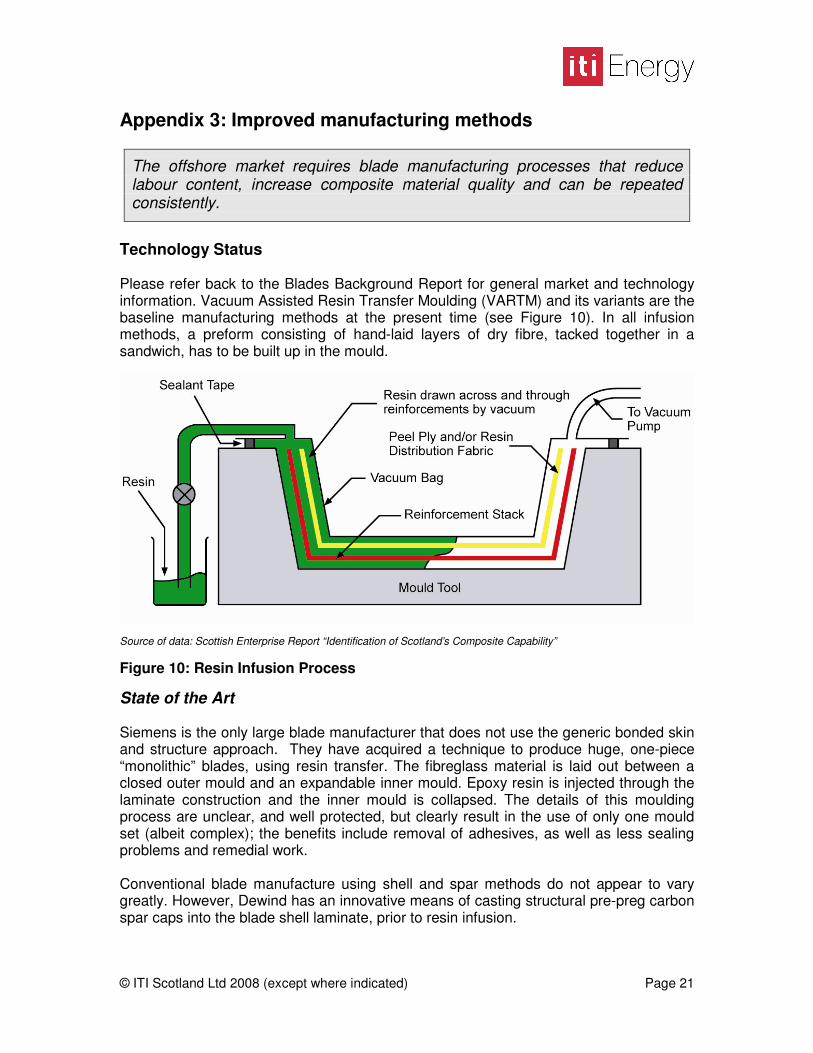
Technology Status Please refer back to the Blades Background Report for general market and technology information. Vacuum Assisted Resin Transfer Moulding (VARTM) and its variants are the baseline manufacturing methods at the present time (see Figure 10). In all infusion methods, a preform consisting of hand-laid layers of dry fibre, tacked together in a sandwich, has to be built up in the mould.
Source of data: Scottish Enterprise Report “Identification of Scotland’s Composite Capability” Figure 10: Resin Infusion Process
State of the Art Siemens is the only large blade manufacturer that does not use the generic bonded skin and structure approach. They have acquired a technique to produce huge, one-piece “monolithic” blades, using resin transfer. The fibreglass material is laid out between a closed outer mould and an expandable inner mould. Epoxy resin is injected through the laminate construction and the inner mould is collapsed. The details of this moulding process are unclear, and well protected, but clearly result in the use of only one mould set (albeit complex); the benefits include removal of adhesives, as well as less sealing problems and remedial work. Conventional blade manufacture using shell and spar methods do not appear to vary greatly. However, Dewind has an innovative means of casting structural pre-preg carbon spar caps into the blade shell laminate, prior to resin infusion.

© ITI Scotland Ltd 2008 (except where indicated) Page 22
There are some manufacturers already using filament winding to produce high performance blade structural spars. Continuous carbon and glass fibre tapes, pre-impregnated with epoxy, are interleaved around a mandrel. Winding is well suited to these types of simple cross section and is likely to become more heavily utilised in this type of application. Similarly, the high volume pultrusion technique is used to produce long strips of material to be laid up in the mould. Vestas is starting to use pre-preg glass fibre and carbon fibre materials in its blade manufacturing processes. Pre-preg materials are pre-impregnated with resin and stored frozen before application. The pre-pregs are laid up by hand or machine in the mould and a vacuum is applied. The pressurised sandwich is heated to between 120 and 1800C; at this temperature the resin starts to reflow and eventually to cure. Blades produced using wet pre-preg materials are generally lighter, stronger, and of higher quality than those produced using dry fibres and VARTM. LM Glassfiber is the world’s largest producer of large wind turbine blades and has largely resisted the use of high performance materials like carbon fibre and pre-preg. They have started to develop ways of automating composite manufacture, which fit nicely with their cost saving drive. LM have cleverly decided to use robots to automate important processes like glass fibre layout and bonding processes. The precision of these methods tends to mean less material can be used with more certainty – and less expensive remedial work. In Development The following manufacturing techniques have been suggested and in some cases demonstrated for small prototype batches. More advanced concepts for preform materials have been discussed in the previous section, but they have enormous potential for improving the manufacturing process. Two dimensional fabrics might be produced offline and even stitched together into a single very large preform. Three dimensional hybrid fabrics might even be slipped over the blade mandrel like a sleeve. As discussed, filament winding is being used in structural spars, but it has also been suggested for complex blade shells. From the 1970s onwards, filament winding of wind turbine blades has been demonstrated by a number of companies. Processes vary, but they all involve a fibre tow (strand), which is dipped in resin and wrapped around a stationary mandrel (Kaman Aerospace), or vice versa (DCS). These techniques allow controllable resin mix, fibre placement and possible cost savings. On the other hand, they rely on a perfectly controlled atmosphere and purely concave shapes. Foam Matrix Inc (FMI) produced an innovative one-piece 4.3 metre long concept for Sandia Labs as part of their economic manufacturing project. The blade has an engineered foam core, incorporating structural members and skinned with composites. It is not clear how large a blade could be produced this way, but it is one way of producing monolithic seamless structures. “Oriented sprayed fibre pre-forms using chopped carbon fibres” (National Composites Centre, US) is a development of the wet hand lay-up method used in boat building and

© ITI Scotland Ltd 2008 (except where indicated) Page 23
early large blades. Carbon fibres tows are chopped into short lengths and mixed with a resin system. Traditional wet lay-up methods have had very poor fibre volume ratios and fibre orientation, but this new technique has shown more promising results. Technology and Market Challenges There are serious issues with the current manufacturing techniques and these will only be amplified as blades get larger (see Table 4). Blade manufacture is labour-intensive and, consequently, susceptible to quality defects related to fibre orientation, material voids, adhesive coverage and tolerance issues. Wet Lay-up Infusion Pre-preg Winding Cost / Part Poor Good Poor Excellent Set-up cost Excellent Excellent Excellent Poor Emissions Poor Excellent Excellent Poor Complexity Good Good Good Poor Consumables Good Excellent Excellent Excellent Consistency of composite Poor Good Excellent Excellent Quality Good Good Excellent Excellent
Table 4: Manufacturing Comparison Matrix In all blades, the thickness of the shell varies throughout and it can be difficult to infuse resin into the thicker sections. This leads to dry spots in the structure, which have to be expensively reworked. The interdependence of material and process is clearly a major issue and can be illustrated by the example of carbon fibre. Carbon’s structural performance, particularly in compression, is highly sensitive to fibre alignment and voids. Therefore, carbon only exacerbates the problems of resin infusion methods and is consequently always utilised in the expensive pre-preg form. Despite these well known problems, resin infusion is dominant in the blade manufacturing industry; this familiarity presents a significant barrier to innovative processes. Major players, like Vestas and Gamesa, make heavy use of the alternative pre-preg process, while other manufacturers, led by LM Glassfiber, have largely resisted and are concentrating on streamlining the current technique. Key Players The key academic and research institutions currently involved in composite manufacturing work are as follows: In the USA, Sandia National Laboratories is running a low cost manufacturing project with multiple competing concepts. The Scottish Enterprise report titled ‘Identification of Scotland’s Composite Capability’ indicates that the University of Glasgow has some academic capability in processing of composite materials. The University of Strathclyde has produced excellent studies on

© ITI Scotland Ltd 2008 (except where indicated) Page 24
mass production for the Talisman Beatrice project. The manufacturing group may be capable of applying this methodology to blade manufacturing analysis. At a UK level, the University of Warwick has a clear focus on advanced manufacturing techniques and may be a good resource. TWI has a track record of process innovation in welding metal and general joining technologies including adhesives and is certainly interested in the wind energy sector.

© ITI Scotland Ltd 2008 (except where indicated) Page 25
ACKNOWLEDGEMENTS ITI Energy would like to acknowledge the following parties for providing permission to use their information in this report: Emerging Energy Research, 700 Technology Square, Cambridge MA 02139, USA www.emerging-energy.com Scottish Enterprise Ayrshire, 17-17 Hill Street, Kilmarnock KA3 1HA www.scotent.co.uk
© ITI Scotland Ltd 2008 (except where indicated) Page 26
SUMMARY OF RESEARCH SOURCES Background Section “Wind Energy – The Facts” European Wind Energy Association, 2002 “Innovative Design Approaches for Large Wind Turbine Blades.” Sandia National Laboratories, March 2003 Ashwill, T.; Laird, D. “Concepts to facilitate very large blades.” Sandia National Laboratories, January 2007 Tangler, J.T. “The Evolution of Rotor and Blade Design”, NREL, May 2000 “Energy Industry Market Forecasts: Renewable Energy: 2007-2012”, Scottish Enterprise, 2007 Gasch, R.; Twele, J. “Wind Power Plants: Fundamentals, Design, Construction and Operation” 2002 Griffin, D. “Blade System Design Studies Volume I: Composite Technologies for Large Wind Turbine Blades”, Sandia National Laboratories, 2002 “Identification of Scotland’s Composite Capability”, Pera Scotland, 2007 http://www.windpower.org/en/tour/wtrb/comp/index.htm http://www.cpi.umist.ac.uk/Eminent/publicFiles/brno/RISO_Future_10MW_Wind_Turbine.pdf Design Section “Innovative Design Approaches for Large Wind Turbine Blades.” Sandia National Laboratories, March 2003 Ashwill, T.; Laird, D. “Concepts to facilitate very large blades.” Sandia National Laboratories, January 2007 Tangler, J.T. “The Evolution of Rotor and Blade Design”, NREL, May 2000 Sherwood, K. “Blade Manufacturing Improvement Project: Final Report”, Sandia National Laboratories, October 2002 Materials Section “Innovative Design Approaches for Large Wind Turbine Blades.” Sandia National Laboratories, March 2003

© ITI Scotland Ltd 2008 (except where indicated) Page 27
Gower, M. “Material R&D Priorities for Wind Power Generation” National Physical Laboratory, June 2007 Ashby, M.; Johnson, K. “Materials and Design: The Art and Science of Material Selection in Product Design”, 2002 http://www.compositesworld.com/hpc/issues/2007/July/111703 http://www.azom.com/default.asp http://pepei.pennnet.com/display_article/282536/6/ARTCL/none/none/New-Structural-Materials-for-Wind-Turbine-Blades/ http://www.goetzboats.com/resources_services/whitepaperpdfs/PrepregvsOtherMethods.pdf Manufacturing Section Tangler, J.T. “The Evolution of Rotor and Blade Design”, NREL, May 2000 Sherwood, K. “Blade Manufacturing Improvement Project: Final Report”, Sandia National Laboratories, October 2002 “Identification of Scotland’s Composite Capability”, Scottish Enterprise, August 2007 “A Due Diligence Assessment of the Manufacturing Technique of the DCS 3BM System for Wind Turbine Blades, With Corollary Marketing Analysis”, ITI Energy Report, June 2006 “Market Study of Wind Turbine Blade Manufacturing”, ITI Energy Report, June 2006 http://www.compositesworld.com/ct/issues/2006/October/1462 http://www.lmglasfiber.com/Technology/Process/Automation.aspx