Offsetting operations in solid modelling - College of …jarek/papers/Offsets.pdf · J.R....
20
Computer Aided Geometric Design 3 (1986) 129-148 129 North-Holland Offsetting operations in solid modelling * Jaroslaw R. ROSSIGNAC IBM, T.J. Watson Research Ctr., Yorktown Heights, NY 10598, USA Aristides A.G. REQUICHA Production Automation Project, Dept. of Electrical Engineering, University of Rochester, Rochester, N Y 14627, USA Received 25 June 1985 Abstract. The range of operations on solids supported by current geometric modelling systems is very limited. Typically, solids represented in a modeller can be transformed by rigid motions and combined by Boolean operations. This paper introduces another family of transformations, called solid offsetting, which map solids into solids. Offset solids are expanded or contracted versions of an original object. Offsetting operations are potentially useful for tolerance analysis, clearance testing, design-rule checking in VLSI, modelling of etching and coating processes, cutter path generation for numerically-controlled machine tools, collision free path planning for robot motions, and for constant-radius rounding and filleting ('blending') of solids. This paper discusses mathematical properties of solid offsetting, associated representations and algorithms, support of offsetting operations in solid modellers, and applications, Results of an experimental implementation are presented. Keywords. Computer aided design, computational geometry, constructive solid geometry, algorithms, offsets, curves, surfaces, approximations. 1. Introduction Solid modelling theory and technology are becoming increasingly well understood, and their commercial and industrial exploitation is progressing rapidly [Requicha and Voelcker '82, '83]. However, the range of operations on solids supported by current modellers is very limited. Typically, solids represented in a modeller can be transformed by rigid motions, which are straightforward and well-known in computer graphics [Newman and Sproull '79, Foley and van Dam '82], and can be combined by Boolean operations, which are complex but important [Requicha and Voelcker '85]. Initial results of research aimed at modelling bending operations have been reported recently [Foumier and Wesley '83, Barr '84]. This paper introduces a new family of transformations, called solid offsetting (abbreviated s-offsetting), that map solids into solids. We discuss mathematical properties of solid offsetting, * The work reported in this paper was supported by the National Science Foundation under Computer Engineering Grants ECS-81-04646 and ECS-84-03882, and by companies in the Production Automation Project's Industrial Associates program. Any opinions, findings, conclusions or recommendations expressed or implied are those of the authors and do not necessarily reflect the views of the N.S.F or the Industrial Associates of the P.A.P. The paper is based in part on Rossignae's Ph.D. Dissertation submitted to the Electrical Engineering Department of the University of Rochester. 0167-8396/86/$3.50 © 1986, Elsevier Science Publishers B.V. (North-Holland)
Transcript of Offsetting operations in solid modelling - College of …jarek/papers/Offsets.pdf · J.R....

Computer Aided Geometric Design 3 (1986) 129-148 129 North-Holland
Offsetting operations in solid modelling *
Jaroslaw R. ROSSIGNAC
IBM, T.J. Watson Research Ctr., Yorktown Heights, N Y 10598, USA
Aristides A.G. REQUICHA
Production Automation Project, Dept. of Electrical Engineering, University of Rochester, Rochester, NY 14627, USA
Received 25 June 1985
Abstract. The range of operations on solids supported by current geometric modelling systems is very limited. Typically, solids represented in a modeller can be transformed by rigid motions and combined by Boolean operations. This paper introduces another family of transformations, called solid offsetting, which map solids into solids.
Offset solids are expanded or contracted versions of an original object. Offsetting operations are potentially useful for tolerance analysis, clearance testing, design-rule checking in VLSI, modelling of etching and coating processes, cutter path generation for numerically-controlled machine tools, collision free path planning for robot motions, and for constant-radius rounding and filleting ('blending') of solids.
This paper discusses mathematical properties of solid offsetting, associated representations and algorithms, support of offsetting operations in solid modellers, and applications, Results of an experimental implementation are presented.
Keywords. Computer aided design, computational geometry, constructive solid geometry, algorithms, offsets, curves, surfaces, approximations.
1. Introduction
Solid modelling theory and technology are becoming increasingly well understood, and their commercial and industrial exploitation is progressing rapidly [Requicha and Voelcker '82, '83]. However, the range of operations on solids supported by current modellers is very limited. Typically, solids represented in a modeller can be transformed by rigid motions, which are straightforward and well-known in computer graphics [Newman and Sproull '79, Foley and van Dam '82], and can be combined by Boolean operations, which are complex but important [Requicha and Voelcker '85]. Initial results of research aimed at modelling bending operations have been reported recently [Foumier and Wesley '83, Barr '84].
This paper introduces a new family of transformations, called solid offsetting (abbreviated s-offsetting), that map solids into solids. We discuss mathematical properties of solid offsetting,
* The work reported in this paper was supported by the National Science Foundation under Computer Engineering Grants ECS-81-04646 and ECS-84-03882, and by companies in the Production Automation Project's Industrial Associates program. Any opinions, findings, conclusions or recommendations expressed or implied are those of the authors and do not necessarily reflect the views of the N.S.F or the Industrial Associates of the P.A.P. The paper is based in part on Rossignae's Ph.D. Dissertation submitted to the Electrical Engineering Department of the University of Rochester.
0167-8396/86/$3.50 © 1986, Elsevier Science Publishers B.V. (North-Holland)
130 J. R. Rossignac, A.A.G. Requicha / Offsetting operations in solid modeling
Fig. 1. A simple L-shaped object (a), a positive offset (b), and a negative offset
(c). (4 (b)
representations and algorithms to support offsetting operations in solid modellers, applications, and experimental results.
Offset solids are expanded or contracted versions of an original object. To s-offset a solid S by a positive distance r one adds to the solid all the points exterior to S that lie within a distance r of the boundary of S. For a negative s-offset one subtracts from the solid all the points of S within a distance r from its boundary. (Formal definitions are given in Section 2 below.) Positive and negative s-offsets for a simple L-shaped ‘2-D solid’ are shown in Fig. 1.
Solid offsetting appears to be very useful. Potential applications are summarized in Section 6 below. They cover a wide range, from tolerance analysis and clearance testing, through modelling of such physical processes as coating or etching, to rounding and filleting - notice the vertex rounding effects in Figs. lb-c.
Operations related to solid offsetting have been used to calculate mass properties of solids [Lee and Requicha ‘82b], to plan collision-free paths for robots [Lozano-Perez and Wesley ‘791, to check design rules in VLSI [Barton and Buchanan ‘SO], and to generate cutter paths for numerically-controlled (NC) machine tools [Pressman and Williams ‘77, Faux and Pratt ‘791. In [Lee and Requicha ‘82b] the primitives in a solid’s CSG representation [Requicha ‘SO] are expanded and contracted to reduce set inclusion and disjointness tests to point membership classification, which determines whether a point is inside, on the boundary of, or outside a solid. In [Lozano-Perez and Wesley ‘791 obstacles are expanded, again to reduce solid interference tests to point membership classification. 2-D objects are expanded and contracted in VLSI applications to detect violations of minimum-distance, maximum and minimum size, and non-overlap rules. In NC and related applications one offsets smooth surfaces by ‘moving along the normal’ by a distance r to generate other surfaces, and offsets planar curves similarly to generate other curves. (We refer to this operation as normal offseting or simply n-offsetting, to distinguish it from solid offsetting.) The current understanding of normal offsetting is summarized in [Tiller and Hanson ‘841 and [Klass ‘831. Briefly, there is no accepted mathemati- cal definition of n-offsetting for surfaces and curves that are only piecewise smooth, and even when surfaces and curves are smooth n-offsetting may lead to cusps and self-intersections. Heuristic approaches proposed in [Tiller and Hanson ‘841 provide reasonable results in many but not all of the possible cases.
Offsetting operations are special cases of so-called Minkowski sums and differences. These are important in the field of geometric probability and have been studied extensively by the french school of ‘mathematical morphology’ [Matheron ‘75, Serra ‘821, which is primarily motivated by problems of texture analysis for geological applications. A few of the properties presented below have been derived independently in the mathematical morphology work.
The remainder of this paper is organized as follows. We begin in Section 2 with formal definitions and mathematical properties of s-offsets, and show that n-offsets are useful to study the boundaries of offset solids. Sections 3 and 4 deal with representations and algorithms for

J.R. Rosslgnac, A.A. G. Requicha / Offsetting operations in solid modelling 131
offset solids. Section 5 discusses an experimental modeller, Section 6 addresses potential applications, and Section 7 summarizes the paper.
2. Mathematical definitions and properties of offsets
In this section we define offsets, list some of their mathematical properties, and discuss the practical importance of these properties. Proofs for most of the results are omitted. They can be found in [Rossignac '85] and involve elementary point-set topology [Mendelson '75].
2.1. Definitions
We model physical solids by r-sets, which are bounded, regular, and semi-analytic subsets of 3-D Euclidean space (E 3) [Requicha '77, '80]. (Recall that a set S is regular if S = kiS, where k and i denote, respectively, topological closure and interior.) The (regularized) positive solid offset of a regular set S by a positive distance r is
ST*r= (p: 3 q ~ S , l i P - q l l ~<r}.
Note that when S is empty, S $ *r is also empty. We refer to positive s-offsetting also as growing or expanding. (Non-regularized positive offsets can also be defined [Rossignac '85], and are called generalized balls in the mathematical literature [Nadler '78]; offsetting operations can also be applied to non-regular sets [Rossignac '85]. Offsets discussed in this paper are assumed to be regularized.)
An equivalent definition is
S l ' * r = U B*(p, r), p~S
where B*(p, r ) = {q: IIq- pll ~< r} and denotes a closed ball of radius r centered at p. This alternative definition shows that one can think of S 1' *r as the volume swept by a solid sphere of radius r as its center moves throughout the set S.
There is yet another equivalent definition in terms of po in t / se t distances. First recall that the distance of a point p to a set S is the minimal distance between p and points of S. More precisely, it is defined as [Nadler '78]
d(p, S) = inf lip - q I[. qES
When S is regular, and hence closed, the greatest lower bound is attained for at least one closest point q of S, and therefore one can replace the infimum with minimum in the definition. There may be several closest points. If p is a point of S, then d(p, S) = 0, and if p is exterior to S, then the closest points q lie in 8S, the topological boundary of S.
The positive offset of a regular and non-empty S can also be defined as
S $ * r = {p: d(p,S)<~r)}.
Thus, to expand S one adds to it all the points whose distances to S do not exceed r. The (regularized) negative solid offset of a non-empty S is defined as the complement of the
expanded complement. More precisely,
S $ *r=c*((c*S)t *r),
where c* denotes regularized complement [Requicha '77, '80]. We refer to negative s-offsets also as contracted or shrunk solids.

132 J.R. Rossignac, A.A.G. Requicha / Offsetting operations in solid modelling
2.2. Equality and inclusion
It follows immediately from the definitions that if two sets A and B are equal, so are their s-offsets by r, i.e., A $ *r = B 1" *r and A $ *r = B J, *r. Note, however, that generally neither A $ * r = B $ * r n o r A $ * r = B $ * r imp lyA=B.
Offsetting preserves inclusion relations. Thus, if A c B, then A 1' *r c B 1' *r and A $ *r c B$*r.
2.3. Closure under offsetting operations
If S is regular, then its solid offsets S $ *r and S $ *r are also regular. Therefore regular sets are algebraically closed under offsetting operations. Offsetting by a finite r clearly preserves boundedness, and we conjecture that it also preserves semi-analyticity, but we have no formal proof.
Algebraic closure of r-sets under offsetting is important. It implies that one can add offsetting operations to a modelling system that supports rigid motions and regularized Boolean operations, and be sure that the resulting sets are valid solids, and therefore can be used in the system as inputs for further operations.
2.4. Rigid motions and Boolean operations
Regularized intersection, union, difference, and complement, denoted respectively n *, w *, - *, c*, are modified versions of their standard set-theoretic counterparts [Requicha '77, '80]. In this paper regularized set operations on solids are called simply Boolean operations.
Rigid motions and Boolean operations are the fundamental means used in CSG for defining corr flex objects in terms of simpler, or primitive solids. It is tempting to s-offset solids defined by CSG by s-offsetting each primitive and combining the results, but it is easy to show by counterexamples that this procedure generally is incorrect.
Rigid motions and s-offsets commute since offsets are defined through distances, which are invariant under rigid motions.
The following properties summarize the relationships between offsetting and Boolean operations.
(c*S) '~*r=c*(S ~ *r), ( c*S) J, *r= c*( S "r *r ),
(A U*B)T * r = ( A T *r) u *(B t *r),
( A n *B)J, * r = ( A $ *r) N *(B ~ *r),
( A - * B ) $ *r = (A $ * r ) - * ( B T * r ) , ( A n *S)$ * r c (A 1" *r) n *(B $ *r),
(A U *B)$ *r ~ (A $ *r) U *(B $ *r).
It follows from these properties thai s-offsetting primitives in a CSG representation of S and combining them yields S T *r only in very special cases. For example, expanding a solid whose CSG definition contains only unions can be done by expanding the primitives and unioning the results.
2.5. Successive offsetting
Growing operations are associative and commutative in the following sense:
(S T *a)~ *b= S 1' * ( a + b ) = ( S 1' *b)~ *a.
J.R, Rossignac, A.A.G. Requicha / Offsetting operations in solid rnoaettmg 133
R~(S)
FXs)
(o)
(b)
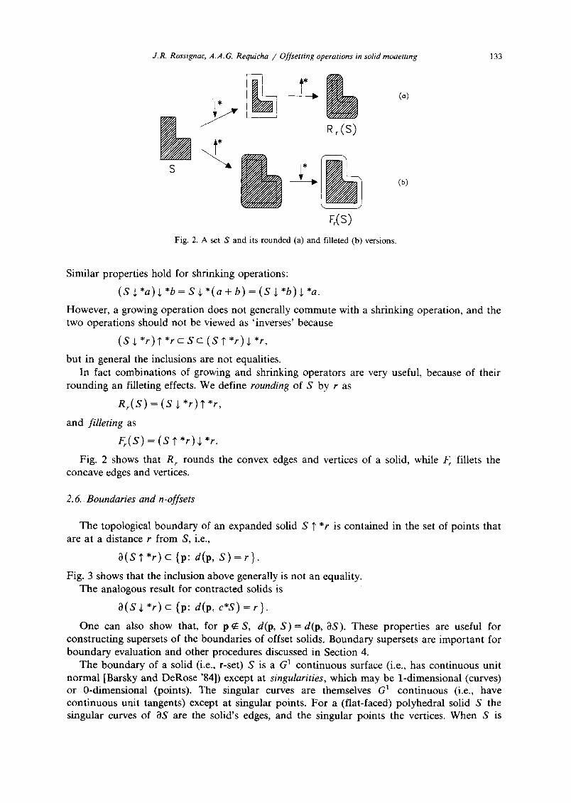
Fig. 2. A set S and its rounded (a) and filleted (b) versions.
Similar properties hold for shrinking operations:
(s +*a)+*b= S b)=(S
However, a growing operation does not generally commute with a shrinking operation, and the two operations should not be viewed as 'inverses' because
(S J, *r) ? *r c S c (S ? *r) $ *r,
but in general the inclusions are not equalities. In fact combinations of growing and shrinking operators are very useful, because of their
rounding an filleting effects. We define rounding of S by r as
R r ( S ) = ( S ~ *r)?*r,
and filleting as
F r ( S ) = ( S ' r *r)j, *r.
Fig. 2 shows that R r rounds the convex edges and vertices of a solid, while F r fillets the concave edges and vertices.
2.6. Boundaries and n-offsets
The topological boundary of an expanded solid S ? *r is contained in the set of points that are at a distance r from S, i.e.,
O ( S ? * r ) c {p: d(p, S ) = r } .
Fig. 3 shows that the inclusion above generally is not an equality. The analogous result for contracted solids is
a ( S ~ *r) c {p: d(p, e 'S) = r }.
One can also show that, for p ~ S, d(p, S ) = d(p, aS). These properties are useful for constructing supersets of the boundaries of offset solids. Boundary supersets are important for boundary evaluation and other procedures discussed in Section 4.
The boundary of a solid (i.e., r-set) S is a G 1 continuous surface (i.e., has continuous unit normal [Barsky and DeRose '84]) except at singularities, which may be 1-dimensional (curves) or 0-dimensional (points). The singular curves are themselves G a continuous (i.e., have continuous unit tangents) except at singular points. For a (flat-faced) polyhedral solid S the singular curves of aS are the solid's edges, and the singular points the vertices. When S is

134 J.R. Rossignac, A.A.G. Requicha / Offsetting operations in solid modelling
J Fig. 3. Point p is at d is tance r from S but
is not on the bounda ry of S 1' *r.
curved the singularities typically are a proper subset of the edges and vertices that appear in the solid's boundary representation.
Let us construct a superset of 0(S t *r). (The same arguments apply to S $ *r.) First observe that, for p ~ S, the distance d(p, S) must be attained for some point q of as, and q must be in one of the following sets:
(1) F = OS-(all singularities); (2) E = (singular curves)-(singular points); (3) V = singular points. We analyze each case separately. Suppose that q c F. Then, in a neighborhood of q there is a
parameterization q = q(u, v), and the distance l i P - q II must reach a minimum, which implies
Oq ~q ( p - q ) - - ~ u = 0 and ( p - q ) - ~ v = 0
where the dot denotes inner product. Therefore the vector p - q is normal to F at q because 0q /0u and Oq/Ov are tangent to the surface. (We assume regular parameterization and therefore Oq/Ou and aq/Ov are not parallel.) Now construct the set F Ilr + by displacing each point q of F by a distance r along the unit normal n at q, i.e., let p = q + rn. F [Ir + is called the positive normal offset, (abbreviated positive n-offset) of F, and is the conventional 'offset
. 7'
. ¸
/ \ . , J .o...! ".~
Fig. 4. Point p is in the n-offset by r of the face F of S bu t its d is tance to S is
less than r.

J.R. Rossignac, A.A.G. Requicha / Offsetting operations in solid modelling 135
surface" used in NC applications, as noted in Section 1. It is clear from the construction that F 117 includes all the points p for which the distance d(p, S) = r is at tained for some q in F. Note, however, that not all points of F ]lr + are at a distance r from S; some may be at a smaller distance, as shown in Fig. 4. Similar arguments show that F I1~-, the negative n-offset of F, defined by displacing q inward by r, contains all points p at distance r from the complement of S. N-offsets of smooth surfaces need not be smooth because they may self-intersect, as shown in Fig. 4 (see [see Willmore '58, p. 117] for self-intersection conditions). In fact, n-offsets of surfaces need not even be surfaces. For example, the negative n-offset by r of a sphere of radius r is a point - the center of the sphere.
Consider now q E E. Parameterizing the curve in a neighborhood of q as q = q(t) and differentiating the distance II P - q II yields
3q (p - q)- -~- = O.
Therefore p must lie in the normal plane to E at q because Oq/3t is tangent to the curve. Since tl p - q II = r, p lies in a circle of radius r and center q in the normal plane. The set of points p
on such circles for all q in E is called the positive n-offset of E. (Negative n-offsets for curves are empty.) E 117 can be viewed as the surface swept by a circle of radius R when its center moves along the trajectory, or spine E. N-offsets for curves are closely related to right circular constant generalized cylinders used in computer vision [Shafer and Kanade '83], and were called canal or tubular surfaces in the mathematical literature of the turn of the century [Monge 1849, Salmon 1882], where they were defined in terms of envelopes of families of spherical surfaces.
Finally, if q ~ V, then q is an isolated point, and we define positive n-offset by r of a point q simply as a spherical surface of radius r centered at q. (Negative n-offsets for points are empty.)
The set obtained by n-offsetting the G l 2-D subsets of 3S, the G 1 1-D subsets of its singular curves, its singular points, and unioning the results is simply called the n-offset of OS. It follows from the previous discussion that the n-offset of OS contains all points at distance r from S, and therefore is a superset of the boundary of the offset solid S 7 *r.
The solids representable in most of the existent solid modellers must be bounded by planes, cylinders, cones, spheres - sometimes called the 'natural quadrics', because they are easy to produce by conventional machining operations such as drilling and milling [Hakala et al. '80] - and tori. (In the sequel we refer collectively to all these surface as standard surfaces.) Importantly, n-offsetting a standard surface produces a surface of the same type. (Note, however, that n-offsetting other quadrics, e.g. an ellipsoid, does not generally produce quadrics.) N-offsetting an edge of intersection of two standard surfaces produces a canal surface with the same spine. We conclude that to support offsetting operations in standard modellers only a new type of surface - a canal surface - must be introduced. The required canal surfaces, however, may be quite complicated because their spines may be the intersection of other canal surfaces, when offset solids are combined by Boolean operations and offset further. Closed form equations for canal surfaces can be obtained readily only in very simple special cases.
3. Computational requirements
Our primary goal is to support offsetting operations in solid modellers that contain both CSG and BReps, and to ensure that offset solids are treated like other solids in the modeller, i.e., that they can be displayed, combined by Boolean operations, further offset, and so forth. This section discusses representational and algorithmic requirements for achieving this goal.
136 J.R. Rossignac, A.A.G. Requicha /Offsetting operations in solid modelling
3.1. Representations
The (conceptually) simplest approach is to treat offsetting operations as ' commands ' that are entered by a user, executed, and discarded. Execution of the commands should produce both CSG and boundary representations for the offset solid that results from the operation. We investigated this approach and found that it is difficult to generate automatically CSG representations for offsets of complicated solids, and that the resulting representations are difficult to manipulate algorithmically. (CSG representations for offsets of simple solids, e.g. blocks, cylinders, spheres and cones, are easy to generate.)
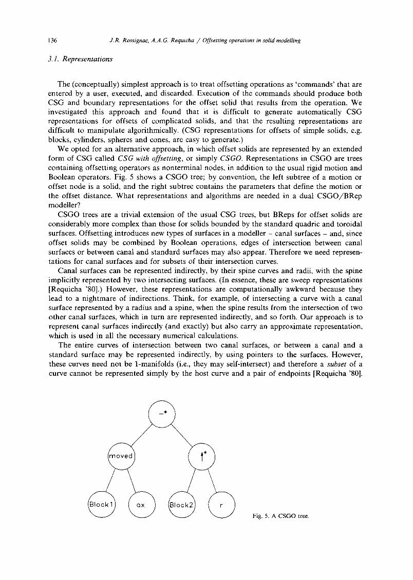
We opted for an alternative approach, in which offset solids are represented by an extended form of CSG called CSG with offsetting, or simply CSGO. Representations in CSGO are trees containing offsetting operators as nonterminal nodes, in addition to the usual rigid motion and Boolean operators. Fig. 5 shows a CSGO tree; by convention, the left subtree of a motion or offset node is a solid, and the right subtree contains the parameters that define the motion or the offset distance. What representations and algorithms are needed in a dual C S G O / B R e p modeller?
CSGO trees are a trivial extension of the usual CSG trees, but BReps for offset solids are considerably more complex than those for solids bounded by the standard quadric and toroidal surfaces. Offsetting introduces new types of surfaces in a modeller - canal surfaces - and, since offset solids may be combined by Boolean operations, edges of intersection between canal surfaces or between canal and standard surfaces may also appear. Therefore we need represen- tations for canal surfaces and for subsets of their intersection curves.
Canal surfaces can be represented indirectly, by their spine curves and radii, with the spine implicitly represented by two intersecting surfaces. (In essence, these are sweep representations [Requicha '80].) However, these representations are computationally awkward because they lead to a nightmare of indirections. Think, for example, of intersecting a curve with a canal surface represented by a radius and a spine, when the spine results from the intersection of two other canal surfaces, which in turn are represented indirectly, and so forth. Our approach is to represent canal surfaces indirectly (and exactly) but also carry an approximate representation, which is used in all the necessary numerical calculations.
The entire curves of intersection between two canal surfaces, or between a canal and a standard surface may be represented indirectly, by using pointers to the surfaces. However, these curves need not be 1-manifolds (i.e., they may self-intersect) and therefore a subset of a curve cannot be represented simply by the host curve and a pair of endpoints [Requicha '80].
Fig. 5. A CSGO tree.
J.R. Rossignac, A.A. G. Requicha / Offsetting operations in solid modelling 137
The standard representations for curve segments in solid modelling are based on parameteriza- tions of the curves, but we do not know of any general methods for parameterizing the intersections of canal surfaces. These difficulties led us to represent edges through para- meterized approximations. We also carry references to the intersecting surfaces, which may be used to refine the approximations when needed.
Edge approximation is a crucial issue in our approach. We divised a new approximation technique, called piecewise constant curvature approximation, which is especially well-suited for solid modelling [Rossignac '85, Rossignac and Requicha '86]. Edges are approximated by piecewise circular curves, and the canal surfaces that result from n-offsetting such edges are approximated by smoothly joined pieces of tori and cylinders. The resulting curves have continuous unit tangents, and the surfaces have continuous unit normals, i.e., both are G 1 geometrically continuous [Barsky and DeRose '84]. (In the sequel we use the abbreviation PCC both as a noun to denote 'piecewise circular curve', and as an adjective to mean 'piecewise constant curvature'.)
In summary, our approach is to represent in BReps the new surfaces and edges introduced by offsets both indirectly (exactly) and by PCC approximations.
3.2. Algorithms
Today's solid modellers have facilities for generating calligraphic and shaded displays of the represented objects, for computing mass properties, and for evaluating the boundaries of objects defined by Boolean operations. What algorithms are needed to support such facilities in a CSGO/BRep system?
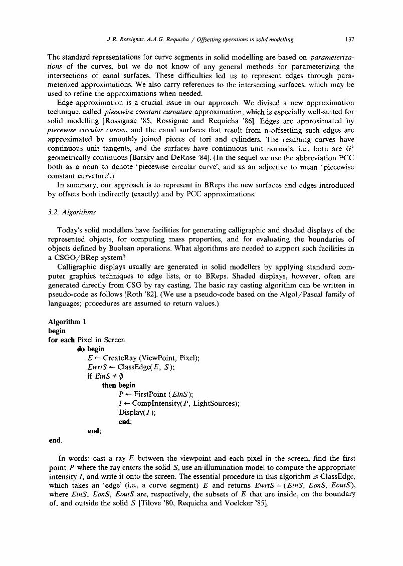
Calligraphic displays usually are generated in solid modellers by applying standard com- puter graphics techniques to edge lists, or to BReps. Shaded displays, however, often are generated directly from CSG by ray casting. The basic ray casting algorithm can be written in pseudo-code as follows [Roth '82]. (We use a pseudo-code based on the Algol/Pascal family of languages; procedures are assumed to return values.)
Algorithm 1 begin for each Pixel in Screen
do begin E ,--- CreateRay (ViewPoint, Pixel); EwrtS ~ ClassEdge(E, S); if EinS ~
then begin P ~ FirstPoint (EinS); I ,--- Complntensity(P, LightSources); Display(l); end;
end; end.
In words: cast a ray E between the viewpoint and each pixel in the screen, find the first point P where the ray enters the solid S, use an illumination model to compute the appropriate intensity I, and write it onto the screen. The essential procedure in this algorithm is ClassEdge, which takes an 'edge' (i.e., a curve segment) E and returns EwrtS = (EinS, EonS, EoutS), where EinS, EonS, EoutS are, respectively, the subsets of E that are inside, on the boundary of, and outside the solid S [Tilove '80, Requicha and Voelcker '85].
13 8 J.R. Rossignac, A.A.G. Requicha / Offsetting operations in solid modelling
There are many methods for computing mass properties of solids [Lee and Requicha '82a], but the most commonly used in dual-representation modellers are based on ray casting or cell classification [Lee and Requicha '82b]. The ray casting algorithm involves the ClassEdge procedure mentioned above. Cell classification requires a procedure ClassPoint(P, S), which determines whether a point P is in the interior, boundary, or complement of a solid S.
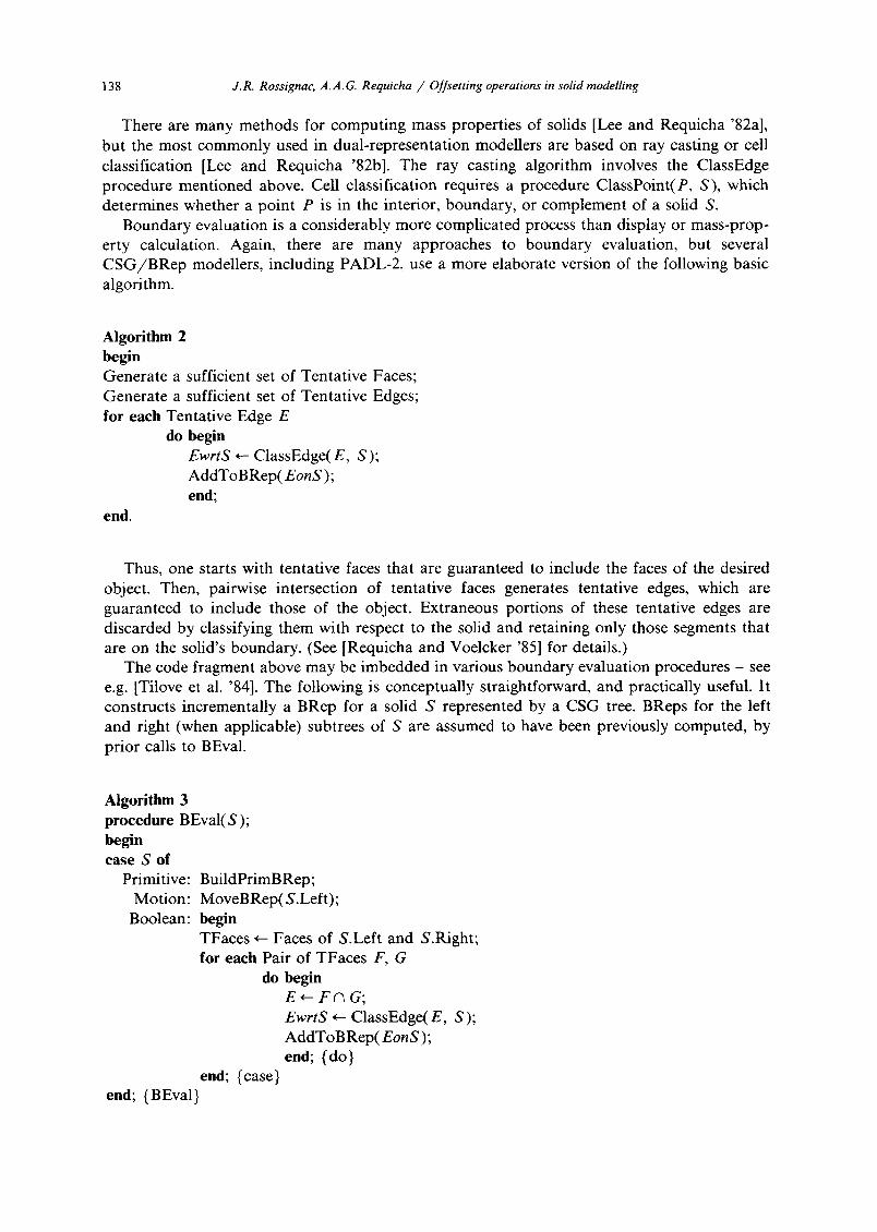
Boundary evaluation is a considerably more complicated process than display or mass-prop- erty calculation. Again, there are many approaches to boundary evaluation, but several CSG/BRep modellers, including PADL-2, use a more elaborate version of the following basic algorithm.
Algorithm 2 begin Generate a sufficient set of Tentative Faces; Generate a sufficient set of Tentative Edges; for each Tentative Edge E
do begin E w r t S ~- ClassEdge(E, S); AddToBRep(EonS); end;
end.
Thus, one starts with tentative faces that are guaranteed to include the faces of the desired object. Then, pairwise intersection of tentative faces generates tentative edges, which are guaranteed to include those of the object. Extraneous portions of these tentative edges are discarded by classifying them with respect to the solid and retaining only those segments that are on the solid's boundary. (See [Requicha and Voelcker '85] for details.)
The code fragment above may be imbedded in various boundary evaluation procedures - see e.g. [Tilove et al. '84]. The following is conceptually straightforward, and practically useful. It constructs incrementally a BRep for a solid S represented by a CSG tree. BReps for the left and right (when applicable) subtrees of S are assumed to have been previously computed, by prior calls to BEval.
Algorithm 3 procedure BEval(S); begin case S of
Primitive: BuildPrimBRep; Motion: MoveBRep(S.Left);
Boolean: begin TFaces ~ Faces of S.Left and S.Right; for each Pair of TFaces F, G
do begin E * - - F ( ~ G;
E w r t S ~ ClassEdge(E, S); AddToBRep( E o n S );
end; {do) end; {case}
end; (BEval}

J.R. Rosszgnac, A.A.G. Requicha / Offsetting operations in solid modelling 139
In words: look at the top node of the CSG tree of S; if S is a primitive simply build its BRep; if it is a rigid motion node, apply the motion to the appropriate BRep; otherwise (the node is a Boolean operator) generate tentative faces by taking the faces of the two subtrees of S, and use Algorithm 2.
Algorithm 3 can be readily modified for operation on CSGO representations. We need to add another branch to the case statement when the node corresponds to an offset operator. The new branch also will use Algorithm 2, but we need a different way to generate tentative faces. We also need procedures to intersect these faces (some of which will lie in canal surfaces), and to classify edges with respect to solids represented in a CSGO/BRep dual scheme.
We conclude that the algorithmic requirements of boundary evaluation subsume those of display generation and mass property calculation. In essence they are: tentative face generation, surface/surface intersection, and edge classification. These three topics will be discussed in the next sections.
4. Boundary evaluation
This section discusses the main components of a boundary evaluation procedure for offset solids. As we saw earlier, the classification procedures required by boundary evaluation also provide means to generate displays and compute mass properties.
4.1. Tentative face generation
At each offset node in a CSGO tree we must generate a sufficient set of tentative faces, whose union is guaranteed to include the boundary of the offset object. This amounts to computing a superset of the boundary of the offset solid S $ *r or S ~ *r, which may be done by n-offseting aS, as shown in Section 2.6. Therefore we must n-offset the smooth faces, and singular curves and points of 3S. The necessary information is contained in the BRep of S, and n-offsetting standard faces, canal faces, curves and points is straightforward.
One must ensure that the BReps used contain all the singularities. For example, the apex of a cone is a singular point and must be n-offset, but is not contained explicitly in many BRep schemes. (A convenient m~thod for generating such isolated singular points in a BRep is to pass through them 'dummy edges' [Rossignac '85].)
Note also that, instead of n-offsetting the actual faces of S, one can n-offset superfaces of S, i.e., 2-D sets that include the actual faces, and still produce a superset of the boundary of the offset solid. This is important because faces my be arbitrarily complex and therefore difficult to n-offset, while superfaces that are geometrically simple can be n-offset easily.
The following facts may be used to generate smaller supersets, and therefore to speed-up tentative face generation, as well as subsequent computations. (We assume below that the positive direction of the normal to the faces or superfaces of S is toward the exterior of S.)
• Negative n-offsets (towards the interior of S) of faces need not be considered when computing tentative faces for S 1" *r. Similarly, positive n-offsets of faces are not needed for S $ * r .
• Concave edges need not be n-offset for S $ *r. Similarly, convex edges are not needed for S ,L *r. BRep edges that separate tangent faces are not singular curves, because the normal to 3S is continuous, and therefore never need to be n-offset.
4.2. Surface~surface intersection
Tentative edges are generated by pairwise intersection of tentative faces. If these lie in natural quadrics, the standard intersection routines of a solid modeller may be used; para-

140 J.R. Rossignac, A.A.G. Requicha / Offsetting operations in solid modelling
Fig. 6. Standard primitives with genera- tors.
meterizations for the resulting edges are readily available. But if the tentative faces are toroidal or are canal surfaces, approximate methods seem inevitable. Our approach has two steps: first we generate points on the intersection, and then we connect them by interpolatory PCCs. These two steps are explained in more detail below.
The curves of constant u and constant v in the 'natural ' parameterizations F(u, v) of the standard surfaces are lines and circles, as shown in Fig. 6. These lines and circles are called
!iiiiiiiiiiti-
b
...... ,7 S?-Sy?STI I?IS-
d
Fig. 7. The intersection-edge between two surfaces S 1 and $2 (a) is obtained by generating intersection-points and corresponding tangents (b), sorting the points in parameter space (c), and interpolating the intersection-points by a
PCC (d).

J.R. Rossignac, .4.A. G. Requicha / Offsetting operations in solid modelling 141
generators. To compute points in the intersection of two tentative faces we intersect a grid of u and v generators of one face with the other face. (We found that both u and v generators must be considered, otherwise intersections almost 'parallel ' to one of the families of generators may be missed entirely.) Because the generators are lines or circles, their intersection with s tandard surfaces can be computed by solving algebraic equations of degree at most four, and this can be done analytically [Rossignac '85]. At each point of the intersection we compute the normals to both faces. The cross product of the normals is the direction of the tangent to the intersection curve.
The result of the first step just described is a set of points and tangents. The second step is more delicate. It involves matching pairs of consecutive points along the curves and using the two points in each pair as endpoints for a span of a PCC approximation. Our matching algorithm is as follows. The intersections between the u and v generators of a face F 1 with a face F 2 are computed and stored. These intersection points lie in the boundaries of grid 'cells' in u, v space - see Fig. 7. We analyze each cell separately. If there are only two intersections in a cell's boundary we match them; otherwise we recursively subdivide the cell until each subcell contains only two intersections or a minimum resolution is reached. Matching at the lowest resolution level is done heuristically. It does not ensure that the topology of the intersection is correct, but such errors have never caused us any difficulties in our solid modelling work. (We experimented with various methods for matching points by using position and tangent information, but none of them are as reliable and efficient as the cell-based approach, which requires essentially no searching.)
N-offseting cones, tori, or canal surfaces may produce self-intersecting surfaces, and the resulting singular curves must be computed because they are needed for further offsetting. Self-intersections of a cone or a torus are easy to compute, and since canal surfaces are approximated by toil and cylinders, their self-intersections can be computed by pairwise comparison of cylindrical or toroidal surfaces using the algorithm described above
4.3. Classification procedures
We describe the necessary classification procedures top down in the following subsections.
4. 3.1. Curve/solid classification The following is a curve / so l id classification procedure that is well suited to CSGO
representations. It assumes that superfaces for the solid S are available. (Other approaches exist - see e.g. [Requicha and Voelcker '85].)
Intersect the curve ('edge') E with the superfaces of S to segment the edge into subsets that have constant classification, i.e., are entirely inS, onS, or outS. Classify a midpoint (or another convenient point) of each segment to determine the segment's classification. In pseudo-code:
Algorithm 4 Procedure ClassEdge(E, S); begin IntList ~- ~; for each superface F of S do AddToIntList(E A F); Sort IntList by parameter value and merge coincident points; for each point Pi but the last in the sorted IntList
do begin q i ~- MidPointOfSegment(p,, p, + 1); CVal ~ ClassPoint(q,, S); Use CVal to induce classification for segment PiP~÷ 1; end; {IntList loop}
end; (ClassEdge}

142 J.R. Rossignac, A.A.G. Requicha / Offsetting operations in solid modelling
If S is a primitive we use its real faces as superfaces, otherwise we use a set of tentative faces computed as explained in Section 4.1. The intersection of an edge E with a superface F in Algorithm 4 may be replaced with the intersection of E and the host surface in which F lies. Edge /sur face intersection is a standard computa t ion in solid modellers. It is usually accom- plished by substituting the parametric definition p(t) of the edge in the implicit equation of the surface f(p) = 0, and solving the resulting equation f (p( t)) = 0 for t.
Procedure ClassEdge calls a po in t / so l i d classifier for midpoints of segments. Note that such points may lie in edges or faces of S, but cannot be vertices of S.
4. 3.2. Point / sofid classification The standard recursive point classification algorithm for CSG [Requicha and Voelcker '77]
can be adapted to CSGO as follows.
Algorithm 5 procedure ClassPoint(p, S); begin case S of
Primitive: ClassPointWrtPrim(p, S); Motion: ClassPoint(M-l(p) , S.Left); (mot ion M}
Boolean: Combine(ClassPoint(p, S.Left), ClassPoint(p, S.Right), S.Op); Offset: ClassPointWrtOffset(p, S);
end; (case} end;
Thus, we add to the case statement in the standard CSG classifier a branch to deal with offset operations. To classify a point p with respect to S = X T *r we use the following procedure. (A similar procedure applies to S = X $ *r.)
Algorithm 6 procedure ClassPointWrtOffset(p, S); begin X ~ S.Left; r ~ S.Right; (Offset distance} if ClassPoint(p, X) = inX or onX
then return inS rise case Dist(p, a X) of
< r: return inS; > r: return outS; = r: if Nbhd(p) = PartFull
then return onS else return inS;
end {case}; end;
We need procedures to evaluate the distance between p and a solid's boundary, and to evaluate the neighborhood Nbhd(p) with respect to an offset solid S. These are discussed in the next two subsections.
4. 3.3. Distance between a point and a solid Algorithm 7 implements the method discussed in Section 2.6. It uses two auxiliary proce-
dures ProjOnCurve and ProjOnSurf that compute normal projections, defined as follows. The
J.R. Rossignac, A.A.G. Requicha / Offsetting operations in solid modelling 143
normal projection set of point p on curve C is the set of points q of C for which the vector p - q is normal to the tangent to C at q. Similarly, the normal projection set of p on surface F is the set of points q of F for which p - q is normal to the tangent plane to F at q. The theory of Section 2.6 implies that the normal projection set contains the point(s) of C or F for which the minimal distance to p is achieved. But it may also contain local minima and maxima of the distance.
Algorithm 7 procedure Dist(p, 0S); begin Drain ~ O; for each singular point q of OS do Dmin ~ min(Dmin, l ip-q tl); for each singular curve C of OS do for each point q of ProjOnCurve(p, C)
do Dmin ~ min(Dmin, II p - q II); for each superface F of S do for each point q of ProjOnSurf(p, Surf(F))
do if ClassPoint(q, S) = onS then Dmin ~ min(Dmin, IIP - q II ); end;
Observe that we project p on the host surface Surf (F) of each superface F of S, and then discard those points in the projection that are not onS and therefore are not in S ' s smooth faces. ProjOnSurf is easy to implement for standard surfaces and hence for PCC approxima- tions of canal surfaces, but projecting p directly on the smooth faces is non-trivial because the faces may be very complex.
ProjOnCurve is straightforward for simple curves such as lines and circles, and hence for PCCs. For a general parameterized curve C(t) evaluation of the normal projection amounts to m i n i m i z i n g liP - C(t)II, and this can be done by setting the first derivative of l iP - C(t)II 2 to zero and solving for t using a root finder.
We presented ClassPointWrtOffset and Dist as separate procedures for simplicity of exposition. But the computat ions may be reorganized for efficiency so as, for example, to return inS as soon as a distance less than r is found.
4. 3.4. Neighborhoods Classification procedures must return neighborhoods for the on segments to disambiguate
situations wherein two solids with overlapping boundaries are combined by a Boolean oper- at ion [Tilove '80, Requicha and Voelcker '85]. For simplicity we ignored this fact in the discussion of algorithms above, but one must add to the returned results EonS or onS a neighborhood representation with respect to S.
Neighborhoods for midpoints of segments in the ClassEdge procedure are essentially two-dimensional and can be represented and combined by standard methods [Requicha and Voelcker '85], provided that neighborhoods with respect to offset solids are available. These can be computed as shown in Fig. 8. Let p be a point at distance r from a solid S, and Let q, be points of 0S where the distance is attained. Then p must be in the intersection of the n-offsets of the faces, singular curves and points in which the q~ lie. Since we also know on which side of the n-offset surfaces is the solid S 1" *r, it is not difficult to generate a s tandard neighborhood representat ion for p.
Point membership classification also is used in Algorithm 7 to discard points on the surfaces of S when comput ing the distance from p to S. We cannot guarantee that such points are in the interiors of edge segments of constant classification, and this leads to difficulties in neighbor- hood manipulat ion. When ambiguous on~on cases are encountered, which happens rarely in the context of distance calculations, one must either use so-called 3-D vertex neighborhoods

144 J.R. Rossignac, A.A. G. Requicha /Offsetting operations in solid modelling
................ F H;
" . . . . r F2
I1~" P ' "
Fig. 8. Computing the neighborhood of point p with respect to S 1' *r.
[Requicha and Voelcker '85], which are rather unwieldy, or the alternative methods discussed in [Rossignac '85].
4.4. Simplified BReps
Boundary information normally contained in a BRep was used in the algorithms described above for only the following three purposes.
• Generate tentative faces. • Intersect a curve with superfaces and segment the curve at the intersection points, in
procedure ClassEdge. • Compute distances to superfaces, singular curves and points. We made no use of the object's actual faces - we used superfaces - and of connectivity data.
We conclude that an elaborate BRep is not needed to support classification calculations in CSGO - and hence' to support boundary evaluation, shaded display generation, mass property calculation, and so on. It suffices to store immediately below each offset node a collection of superfaces, singular curves, and singular points of the object to be offset. Explicit connectivity information such as face /edge incidence relations also is not needed. We call such 'minimal ' BReps superface/curve/point (abbreviated SCP) representations. They also are adequate to support generation of line drawings by standard computer graphics techniques, and may be used profitably when a full-blown dual CSGO/BRep modeller is not needed.
5. An experimental implementation
An experimental modeller was designed and implemented to demonstrate that the ideas in this paper are viable. It is based on CSGO representations with the standard primitives: cuboids, cylinders, cones, spheres and tori. For simplicity, we used SCP representations for boundaries (see Section 4.4), and approximated all edges by PCCs. (We d o not advocate PCC approximation for edges that can be represented exactly in a production-grade modeller, because algorithms based on PCCs are slower and potentially less reliable than exact calcula- tions.) We also ignored neighborhoods, and therefore the experimental modeller may produce incorrect results, e.g. when objects with overlapping boundaries are combined by Boolean operations.
The modeller is written in Pascal and uses the algorithms discussed earlier. Superfaces in SCP representations are either faces of primitives or n-offsets generated at offset nodes.
Figs. 9 and 10 show examples of line drawings and shaded displays generated by the modeller.

J.R. Rossignac, A.A. G. Requicha // Offsetting operations in solid modelling 145
Fig. 9. Line drawings generated by our experimental modeller.
Fig. 10. Shaded display generated by our experimental modeller.
146 J.R. Rossignac, A.A.G. Requicha / Offsetting operations in solid modelling
6. Applications
6.1. Blending
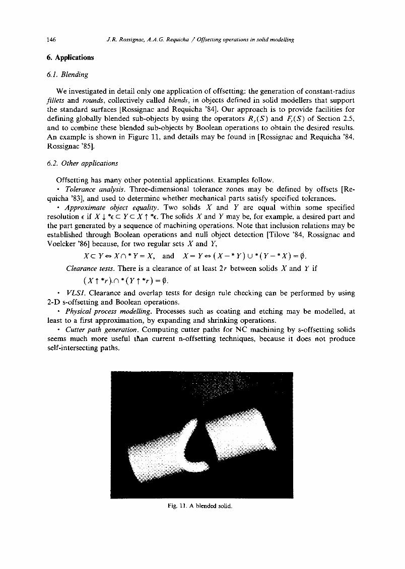
We investigated in detail only one application of offsetting: the generation of constant-radius fillets and rounds, collectively called blends, in objects defined in solid modellers that support the standard surfaces [Rossignac and Requicha ‘841. Our approach is to provide facilities for defining globally blended sub-objects by using the operators R,(S) and F,(S) of Section 2.5, and to combine these blended sub-objects by Boolean operations to obtain the desired results. An example is shown in Figure 11, and details may be found in [Rossignac and Requicha ‘84, Rossignac ‘851.
6.2. Other applications
Offsetting has many other potential applications. Examples follow. l Tolerance analysis. Three-dimensional tolerance zones may be defined by offsets [Re-
quicha ‘831, and used to determine whether mechanical parts satisfy specified tolerances. l Approximate object equality. Two solids X and Y are equal within some specified
resolution e if X J. *c c Y c X T *e. The solids X and Y may be, for example, a desired part and the part generated by a sequence of machining operations. Note that inclusion relations may be established through Boolean operations and null object detection [Tilove ‘84, Rossignac and Voelcker ‘861 because, for two regular sets X and Y,
xcY=xn*Y=X, and X=Y=(X-*Y)U*(Y-*X)=g.
Clearance tests. There is a clearance of at least 2r between solids X and Y if
(X?*r),n*(Yr*r)=$.
l VLSI. Clearance and overlap tests for design rule checking can be performed by using 2-D s-offsetting and Boolean operations.
l Physical process modelling. Processes such as coating and etching may be modelled, at least to a first approximation, by expanding and shrinking operations.
l Cutter path generation. Computing cutter paths for NC machining by s-offsetting solids seems much more useful than current n-offsetting techniques, because it does not produce self-intersecting paths.
Fig. 11. A blended solid.

J.R. Rossignac, A.A. G. Requicha /Offsetting operations in sofid modelling 1 4 7
Obstacle avoidance. Let B be a ball of radius r that encloses an object X. Then X can move without colliding with obstacles Y if there is a curve C (traced by the center of B) such that C n (Y 1' *r) = ¢.
7. Summary and conclusions
This paper discussed a new family of operations on solids, called solid offsetting, and their incorporation in m o d e m solid modellers that contain dual Constructive Solid Geometry (CSG) and boundary representations. Offsetting operations may be used to round and fillet solids, and have many other potential applications.
An extended form of CSG, called CSG with offsetting (CSGO) was defined, and algorithms needed to support display generation, mass property calculation, and boundary evaluation on CSGO were presented. These algorithms use non-trivial extensions of known CSG-based methods.
Piecewise constant curvature approximations, discussed in detail elsewhere [Rossignac '85, Rossignac and Requicha '86], were used to represent intersection edges. The resulting piecewise circular curves lead to simple and efficient procedures for computing edge/surface intersec- tions, and distances of points to curves, which are needed by CSGO algorithms.
Experimental results show that the methods discussed are viable, but more effort is needed to improve substantially the efficiency of the algorithms. Known techniques for enhancing the average performance of geometric algorithms [Tilove 81] may hold the key to fast offsetting computations.
References
Barr A.H. (1984), Global and local deformations of solid primitives, SIGGRAPH'84 Conference Proceedings, Computer Graphics 18, 21-30.
Barsky B.A. and DeRose T.D. (1984), Geometric continuity of parametric curves, Report No. UCB/CSD 84/205, University of California, Berkeley.
Barton E.E. and Buchanan I. (1980), The polygon package, Computer Aided Design 12, 3-11. Faux, I.D. and Pratt, M.J. (1979), Computational Geometry for Design and Manufacture, Ellis Horwood, Chichester,
U.K. Foley J.D. and Van Dam A. (1982), Fundamentals of Interactive Computer Graphics, Addison-Wesley, Reading, MA. Fournier A. and Wesley M.A. (1983), Bending polyhedral objects, Computer Aided Design 15, 79-87. Hakala D.G., Hillyard R.C., Malraison P.J., and Nourse B.E. (1980), Natural quadrics in mechanical engineering,
CAD/CAM VIII, Autofact West, Anaheim, California. Klass R. (1983), An offset spline approximation for plane cubic splines, Computer Aided Design 15, 297-299. Lee Y.T. and Requicha A.A.G. (1982a), Algorithms for computing the volume and other integral properties of solids: I
- Known methods and open issues, Comm. ACM 25, 635-641. Lee Y.T. and Requicha A.A.G. (1982b), Algorithms for computing the volume and other integral properties of solids:
A family of algorithms based on representation conversion and cellular approximation, Comm. ACM 25, 642-650. Lozano-Perez T. and Wesley M.A. (1979), An algorithm for planning collision-free paths among polyhedral obstacles,
Comm. ACM 22, 560-570. Matheron G. (1975), Random Sets and lntegral Geometry, Wiley, New York. Mendelson B. (1975), Introduction to Topology, Allyn and Bacon, Boston, 3rd ed. Monge G. (1849), Applications de l'Analyse h la Gbombtrie, Bachelier, Paris, 5th ed. Nadler S.B. Jr. (1978), Hyperspaces of Sets, Marcel Dekker, New York. Newman W.M. and Sproull R.F. (1979), Principles oflnteractwe Computer Graphics, McGraw-Hill, New York, 2nd ed. Pressman R.S. and Williams J.E. (1977), Numerical Control and Computer-aided Manufacturing, Wiley, New York. gequicha A.A.G. and Voelcker H.B. (1977), Constructive solid geometry, Tech. Memo. No. 25, Production Automation
Project, Univ. of Rochester. Requicha, A.A.G. (1977), Mathematical models of rigid solid objects, Tech. Memo. 28, Production Automation Project,
Univ. of Rochester.

148 J.R. Rossignac, A.A.G. Requicha /Offsetting operations in solid modelling
Requicha A.A.G. (1980), Representations for rigid solids: theory, methods, and systems, ACM Computing Surveys 12, 437-464.
Requicha A.A.G. and Voelcker H.B. (1982), Solid modelling: A historical summary and contemporary assessment, IEEE Computer Graphics and Applications 2, 9-14.
Requicha A.A.G. and Voelcker H.B. (1983), Solid modelling: current status and research directions, IEEE Computer Graphics and Applications 3, 25-37.
Requicha A.A.G. (1983), Toward a theory of geometric Tolerancing, Internat. J. Robotics Research 2, 45-59. Requicha A.A.G. and Voelcker H.B. (1985), Boolean operation in solid modelling: Boundary evaluation and merging
algorithms, Proc. IEEE 73, 30-44. Rossignac J.R. (1985), Blending and offsetting solid models, TM 54 (Ph.D. dissertation), Production Automation
Project, University of Rochester. Rossignac J.R. and Requicha A.A.G. (1984), Constant radius blending in solid modelling, Computers in Mechanical
Engineering 3 (1), 65-73. Rossignac J.R. and Requicha A.A.G. (1986), Piecewise constant curvature approximation for solid modelling, TM 63
(in draft), Production Automation Project, University of Rochester. Rossignac, J.R. and Voelcker, H.B. (1986), Active zones in constructive solid geometry for redundancy and interference
detection, TM 52, Production Automation Project, University of Rochester. Roth S.D. (1982), Ray casting for modeling solids, Computer Graphics and Image Processing 18 (2), 109-144. Salmon, G. (1882), A Treatise on the Analytic Geometry of Three Dimensions, Hodges, Figgis and Co., Dublin, 4th ed. Serra J. (1982), Image Analysis and Mathematical Morphology, Academic Press, London. Shafer S. and Kanade T. (1983), The theory of straight homogeneous generalized cylinders, Report CMU-CS-83-105,
Computer Science Dept., Carnegie-Mellon University. Tiller W. and Hanson E.G. (1984), Offsets of two-dimensional profiles, IEEE Computer Graphics and Applications 4
(9), 36-46. Tilove R.B. (1980), Set membership classification: a unified approach to geometric intersection problems, IEEE Trans.
Computers 29 (10), 874-883. Tilove, R.B. (1981), Exploiting spatial and structural locality in geometric modelling, Tech. Memo. 38, Production
Automation Project, Univ. of Rochester. Tilove R.B. (1984), A null-object detection algorithm for constructive solid geometry, Comm. ACM 2 (7), 684-694. Tilove R.B., Requicha A.A.G., and Hopkins M.R. (1984), Efficient editing of solid models by exploiting structural and
spatial locality, Computer Aided Geometric Design 1,227-239. Willmore T.J. (1958), Differential Geometry, Oxford University Press.