OFC Networks: PON, GPON and Radio on Fiber. OFC Networks- PON... · OFC Networks: PON, GPON and...
72
OFC Networks: PON, GPON and Radio on Fiber PRESENTED BY: Dr. BALJEET KAUR ASSISTANT PROFESSOR DEPARTMENT OF ECE, GNDEC LUDHIANA
Transcript of OFC Networks: PON, GPON and Radio on Fiber. OFC Networks- PON... · OFC Networks: PON, GPON and...
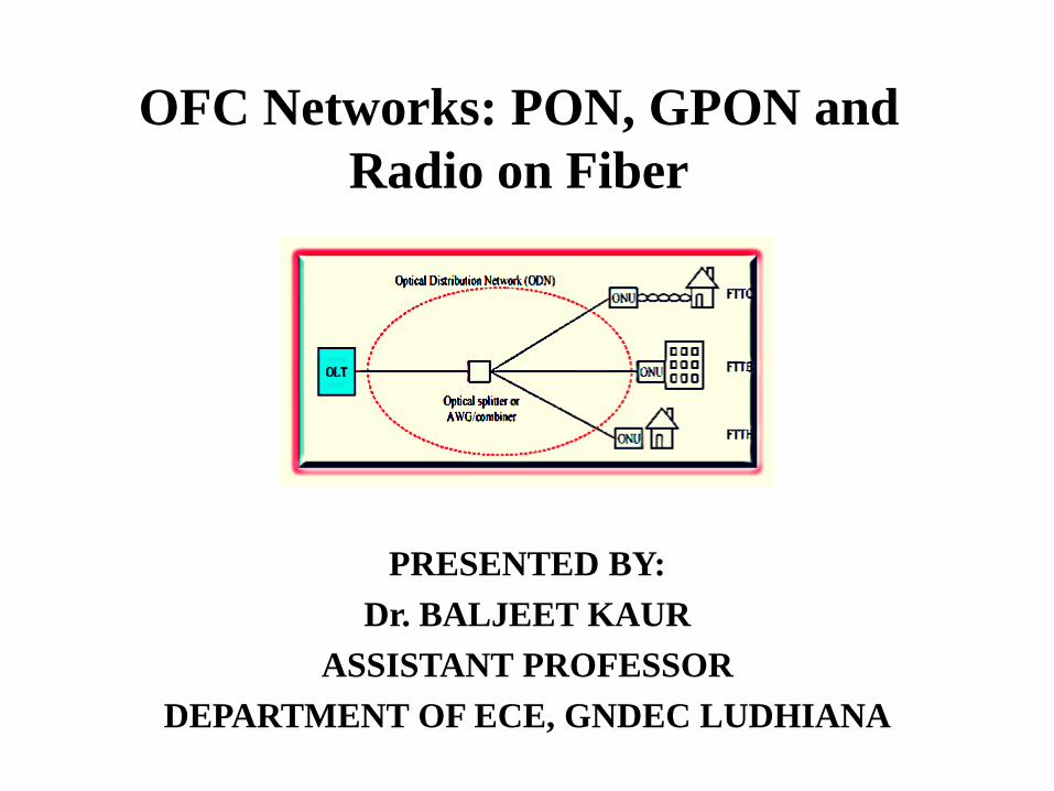
OFC Networks: PON, GPON and
Radio on Fiber
PRESENTED BY:
Dr. BALJEET KAUR
ASSISTANT PROFESSOR
DEPARTMENT OF ECE, GNDEC LUDHIANA

PON and GPON
Motivation
• Increased dependency on internet information across the globe.
• Traffic increase by more than 100% in a year.
• Every minute more than 12 million email messages move across the internet
and about half-a-million voice mail messages move in a minute.
• More than 100 million people log on to the internet in a day to access various
types of information.
• Neither DSL(Digital subscriber loop) nor CMs (cable modems) can keep up
with such high demand. Both technologies are built on top of existing copper
communication infrastructure not optimized for data traffic.
• DSL and CMs can not support full service voice(telephone),video (TV) and data
(Internet access) networks.
• Most network operators have come to the realization that a new data-centric
solution is necessary. Such a technology would be optimized for IP data traffic.
• Passive Optical Network (PON) is a technology viewed by many as an attractive
solution to this problem.
• A PON allows for longer distances between central offices and customer premises
while with DSL the maximum distance between the central office and the customer is
only approximately 5.5 km, a PON local loop can operate at distance of over 20 km.

Local Area Networks
• use copper cable
• get high data rates over short distances
Core Networks
• use fiber optics
• get high data rates over long distances
Access Networks (Weak Spots) Fig. 1
Access network is a part of telecommunication network that connects subscribers
to their service providers. It is the network between Central Office (CO) and end
users. It is Hard for end users to get high data rates because of the access bottleneck
• long distances
so fiber would be the best choice
Core Access
LAN
Where PON required?

The logical ways to deploy optical fiber in the local access network are :
˙Point-to-Point (P2P)
˙Curb-switched network
˙Passive optical network (PON)
Why PON?

PON Architecture
PRBS
Generator
NRZ Pulse Generator
CW Laser MZ
Modulator Photo detector
LPF
Visualizer
OLT
OLT-OPTICAL LINE TERMINAL
ODN-OPTICAL DISTRIBUTION NETWORK
ONU-OPTICAL NETWORK UNIT
Fig.3 –Passive Optical Network Architecture
Splitter
ODN
ONU
Downstream
1550 nm
1310 nm
Upstream
PON consists of a CO node, called an optical line terminal
(OLT), one or more user nodes, called optical network units
(ONUs) or optical network terminals (ONTs), and fibers and
splitters between them, called the optical distribution
networks (ODNs) .
PONS are called "passive" because, other than at the central
office (CO) and subscriber endpoints, there are no active
electronics within the access network.
Hence, due to the lack of active units in the light path the
architecture of PON is simple, cost effective and it offers
virtually unlimited bandwidth to the subscriber that is not
possible to achieve by other access netwoks.

Passive
Devices
ODN
PON Overview
OLT: Optical Line Terminator
ONU: Optical Network Unit
ODN: Optical Distribution Network
Depending on where the PON terminates, the system can be described as fiber-to-
the-curb ( FTTC), fiber-to-the-building (FTTB), or fiber-to-the-home (FTTH).

ITU-T G.983
ATM-PON (APON)
• The first Passive optical network standard Based on ATM
• Typical data rate: 54 Mbps to 155 Mbps
Broadband PON (BPON)
• Support 622 Mbps
IEEE 802.3ah Ethernet PON (EPON)
• Completed in 2004 as a part of the first mile project
• Data rate: 1.25 Gbps in both downstream and upstream direction and based on Ethernet protocol
ITU-T G.984 Gigabit PON (GPON) -
• 2.5 Gbps in downstream direction and 1.25 Gbps in upstream direction
GPON is today’s frontrunner in Europe, while EPON has been massively deployed in Asia.
Types of PON

Current Access Technologies
Service Medium Downstream
(Mb/s)
Upstream
(Mb/s)
Maximum
Reach (Km)
ADSL Twisted pair 15 3.8 5.5
VDSL Twisted pair
100 30 0.5
HFC Coax cable 40 9 25
Wi-Fi
Free Space 54 54 0.1
Wi - MAX Free Space 134 134 5
B-PON
Fiber 622 155 20
E-PON Fiber 1000 1000 20
G-PON Fiber 2500 1500 20

Comparison between EPON and GPON E-PON G-PON
Standard ITU.T IEEE
Framing Ethernet GEM
Maximum bandwidth 1.25 Gb/s (↑↓)
2.5 Gb/s (↓)
1.25 Gb/s (↑ )
User Per PON 16-32 32-64
Bandwidth per user 30-60 Mb/s 40-80 Mb/s
Broadband Efficiency 92% 72%
Application Mode Multiservice/ FTTx Pure Data Service
Maturity Large Vendors Involved Small Vendors Involved
GEM- G-PON encapsulation mode

PON Advantages
• Higher line rates : Due to high data capacity of fiber.
• Longer physical reach: allows reach of over 20 km without
amplification, as optical fiber has much less attenuation.
• Equipment sharing: E/O components and electrical devices at the
CO are shared amongst a large number of subscribers.
Reduced maintenance cost: as no need of providing power to
electrical devices in the field.

In Downstream traffic only OLT can send data, no danger of collisions.
In Upstream traffic all ONUs can send data, need collision prevention
mechanism.
Ethernet offers CSMA/CD: Works but doesn‘t avoid collisions and
wastes bandwidth.
Solution: multiplexing (multiple access)
Divide the physical media into multiple virtual medias, offer each ONU
a separate channel.
Several types of multiplexing
Time Division Multiplexing (TDM)
Wavelength Division Multiplexing (WDM)
Hybrid WDM/TDM PON
Current Status of PON

PON Multiplexing Techniques
a) TDM PON
b) WDM -PON
PON Multiplexing architectures. (a) TDM-PON (b)WDM-PON (c) WDM-TDM PON

TDM-PON
• Remote node containing optical power splitters, connects OLT to
many ONUs.
• In the downstream direction, all the broadcasted information is
received at every ONU through splitter.
• At the ONU, the relevant packet with correct address label is
processed and all other data is discarded.
PON Multiplexing architecture TDM-PON

Disadvantages of TDM-PON
Shared traffic structure is a major roadblock for the future development
of TDM-PON.
• Furthermore, the use of optical power splitter leads to security issues
and significant power losses .
• 1:32 optical splitter imposes more than 17 dB insertion loss.

WDM-PON
WDM-PON is a promising solution to improve the performance such as
bandwidth, security and power loss.
• Signals are coded on separate wavelength channels.
• Wavelength splitting done at passive (de-) multiplexer by AWG (Arrayed
waveguide grating).
PON Multiplexing architecture WDM-PON

Contd….
• Reduced insertion loss (i.e. 3-5 dB caused by AWG) helps to improve the
power budget as well as increasing the transmission distance.
• This approach creates a point-to-point (PtP) link where a dedicated
wavelength channel is reserved between the OLT and each ONU.
• Thus, each ONU can operate at the full bit rate of its own wavelength
channel.
Disadvantage:
• Cost: Each user requires its own dedicated transceiver at the OLT.
• The AWG filter is more expensive than the splitters used with GPON,
EPON, and BPON.

Hybrid WDM/TDM PON
• PON combining WDM and TDM technologies called HPON is the most
promising candidate for Next-Generation Optical Access (NGOA) networks.
• High split ratio (large no. of users) is provided by TDM-PONs and large
number of wavelengths and high capacity per wavelength offered by WDM-
PONs.
PON Multiplexing architecture WDM/ TDM-PON

Types of WDM/TDM-PON
1. Static WDM/TDM-PON
Each wavelength can be shared by several ONUs, and the
wavelength assigned to an ONU remain unchanged from
installation until disconnection.
2. Dynamic WDM/TDM-PON
ONU wavelength assignment can be dynamically changed
during communication/operation.


Challenges to WDM and Hybrid PON
• Relatively high cost of the WDM components.
• In a WDM-PON, each OLT and ONU needs a different wavelength
for downstream and upstream transmission, introducing a serious
operational and economical issue.
• Many research efforts are focused on to realize the colorless ONU
i.e. wavelength independent ONU so to achieve low cost
transceiver.

Colorless ONU
• A colorless ONU will support all wavelength channels, reducing
cost through volume production of one component.
• Therefore, ONU must contain tunable transmitter and receiver
devices.
• A tunable filter is used to select or tune to any of the downstream
wavelengths and tunable laser is used to provide colorless upstream
transmitter.
.

Hybrid TWDM-PON/ Wireless access
networks (Fi-wi)
• Wireless and optical technologies are playing a crucial role in
modern access networks.
• Service operators are looking for optical and wireless
integration, so to combine WTDM-PONs with emerging
broadband wireless access technologies such as WiMAX,
WiFi.
• Complementary features, i.e. high capacity provided by optical
network and mobility offered by wireless network are
exploited so to enable the delivery of quad-play services
(video, data, voice and mobility).

Contd…
•The optical backhaul is a
Hybrid-PON which contains
an OLT at CO, SMF, RN, and
multiple access points (APs).
•The wireless front-end
consists of widespread APs to
penetrate numerous wireless
end users (WEUs).
Fig.19 – Wireless optical access network architecture[]

Conclusion
• WDM and Hybrid technology offers a great promise to meet NG-
PON requirements and have several advantages over TDM PONs.
• But there are several disadvantages such as high cost ONUs for P2P
links in WDM PON.
• Future research efforts devoted to solve the issue will provide a way
out of this.
Related Publications
• Next Generation Optical Access Networks: A Review , Avneet Kaur,
Baljeet Kaur and Kuldeepak Singh, Proceedings of 4th International
Conference on Advancements in Engineering & Technology (ICAET-
2016), ISBN No. 978-81-924893-1-5.
• Design and Performance Analysis of Bi-directional TWDM OFDM-
PON with wavelength reuse Scheme, Avneet Kaur, Baljeet Kaur and
Kuldeepak Singh, IEEE international conference on Recent Trends in
Electronics Information Communication Technology, May 20-21, 2016,
India.
• Performance Analysis of Hybrid TDM-WDM 10G –PON and 40G-
PON for NG-PON, Avneet Kaur , Baljeet Kaur, International Conference
on Soft Computing, Intelligent Systems and Applications , Springer
Advances in Intelligent Systems and Computing Series.

References
[1] A.O. Aldhaibani, S.M. Iris and Zulkilfi N., “ 2.5 Gb/s Hybrid WDM/TDM PON using
Radio Over Fiber Technology,” Optik, vol.124, pp.3678-3681, 2013.
[2] A. Chenika , A. Temmar and O. Seddiki , “Transmission of 4× 40/10 Gbps in a WDM-
PON using NRZ-DQPSK/ASK modulation,” Optik ,vol.125,pp.-6296-6298, 2014.
[3] M. E. Abdalla , S. M. Idrus & A. B. Mohammad , “ Hybrid TDM-WDM 10G-PON for
High Scalability Next Generation PON,” Industrial Electronics and Applications (ICIEA)
,8th IEEE Conference, 2013.
[4] Y. Luo, X. Zhou , F. Effenberger, X. Yan, G. Peng, Y. Qian, and Y. Ma , “ Time- and
Wavelength-Division Multiplexed Passive Optical Network (TWDM-PON) for Next-
Generation PON Stage 2 (NG-PON2),” IEEE Journal Of Lightwave Technology, Vol. 31,
No.4,2013.

[5] M.S. Ahsan, M.S. Lee, S. H. Shah Newaz and S.M. Asif , “ Migration to the Next Generation
Optical Access Networks Using Hybrid WDM/TDM-PON ,” Journal of Networks ,Vol 6, no.
1, pp.18-25, January 2011.
[6] S. Bindhaiq , A. S. M. Supa'at, N. Zulkifli, A. B. Mohammad, R. Q. Shaddad , M. A.
Elmagzoub , A. Faisal , “Recent development on time and wavelength-division multiplexed
passive optical network (TWDM-PON) for next-generation passive optical network stage 2
(NG-PON2) ,” Optical Switching and Networking, vol.15,pp. 53-66, 2015.
[7] I. Mohamed and M.S. Ab-Rahman, “ Options and challenges in next-generation optical access
networks (NG-OANs) ,” Optik, vol.126, pp. 131-138 , 2015.
[8] Y. Luo , X. Zhou, F. Effenberger, X. Yan , G. Peng , Y. Qian , and Y. Ma , “ Time- and
Wavelength-Division Multiplexed Passive Optical Network (TWDM-PON) for Next-
Generation PON Stage 2 (NG-PON2),” IEEE Journal Of Lightwave Technology, Vol. 31,
No.4,2013.
[9] J. Kani, “Enabling Technologies for Future Scalable and Flexible WDM-PON and
WDM/TDM-PON Systems,” IEEE Journal Of Selected Topics In Quantum Electronics, Vol.
16, No. 5, pp. 1290-1297,October 2010.

Radio Over Fiber (RoF)

• To meet the explosive demands of high capacity and broadband
wireless access, modern cell based wireless networks have trends
i.e. continuous increase in the number of cells and utilization of
higher frequency bands.
• It leads to a large number of base stations (BSs) to be deployed,
therefore cost effective BS deployment is a key to success in the
market. In order to reduce the system cost Radio over Fiber (RoF)
has been proposed since it provides functionally simple BSs that are
interconnected to a central control station (CS) via an optical fiber.
Radio over Fiber (RoF)
Radio over Fiber (RoF)
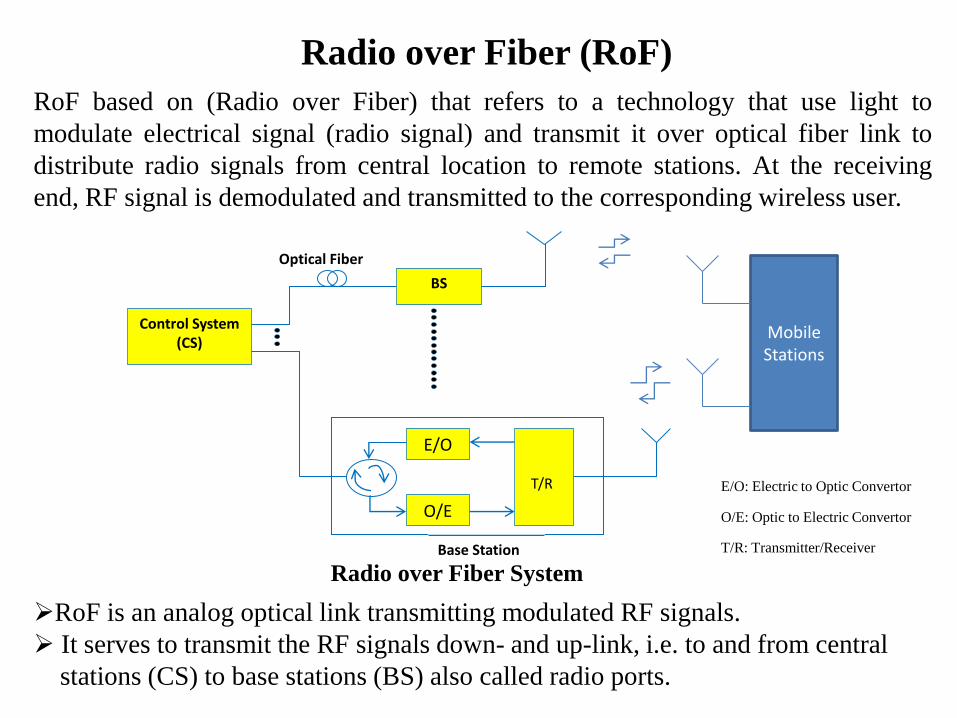
RoF based on (Radio over Fiber) that refers to a technology that use light to
modulate electrical signal (radio signal) and transmit it over optical fiber link to
distribute radio signals from central location to remote stations. At the receiving
end, RF signal is demodulated and transmitted to the corresponding wireless user.
RoF is an analog optical link transmitting modulated RF signals.
It serves to transmit the RF signals down- and up-link, i.e. to and from central
stations (CS) to base stations (BS) also called radio ports.
Control System (CS)
BS
E/O
O/E
Base Station
Optical Fiber
T/R E/O: Electric to Optic Convertor
O/E: Optic to Electric Convertor
T/R: Transmitter/Receiver
Radio over Fiber System
Mobile Stations

TYPES OF CELLULAR NETWORKS
• MACROCELL
• MICROCELL
• PICOCELL

A macrocellular network
is deployed using large
cell with distance of 16 to
48 Km. This network
uses fewer sectors. A
regional switching
centre controls
interconnection with
PSTN.
MACROCELL

– Microcellular radio networks used in areas with high traffic density, like suburban areas. The cells have radii between 200 m and 1km .
– To support growing number of mobile users and to support frequency reuse increase, the cells may be subdivided into smaller units called microcells.
– Thus Microcells increase capacity and also reduce power consumption & size of handset devices.
MICROCELL

PICOCELLS
• A picocell with cell sizes of 4 to 200 meters is a small
cellular base station typically covering a small area, such as in-
building (offices, shopping malls, train stations, stock
exchanges, etc.), or more recently in-aircraft.
• In cellular networks, picocells are typically used to extend
coverage to indoor areas where outdoor signals do not reach
well, or to add network capacity in areas with very dense
phone usage, such as train stations or stadiums.
• Picocells provide coverage and capacity in areas which are
difficult or expensive to reach using the more
traditional macrocell approach

In a RoF system, most of the signal processing (including coding,
Multiplexing, and RF generation and modulation) are carried out by the
Central Office (CO), which makes the Base Station (BS) cost-effective. RoF technique has the potentiality for the backbone of the wireless
access network. Such architecture can give several advantages, such as reduced complexity at the antenna site, radio carriers can be allocated dynamically to different antenna sites, transparency and scalability.
Benefits of RoF Technology
Applications
Cellular network
Satellite Communication
Video distribution system
Mobile Broadband services
Wireless LAN

Merging of WDM PON with Radio over Fiber
Networks
Mobile traffic is rapidly increasing to access variety of services and
their access methods diversifies in various types of radio air interfaces.
This trend requires the more and more efficient use of radio frequency,
and the reduction of radio cell size for wireless access.
WDM-PON is investigated for its large data bandwidth, enhanced
security, and scalability to support several local subscribers. Integrating
a mm-wave RoF system with a WDM-PON (WDM-RoF-PON) is a
very attractive solution to significantly increase the overall capacity
and coverage area of the RoF access networks.
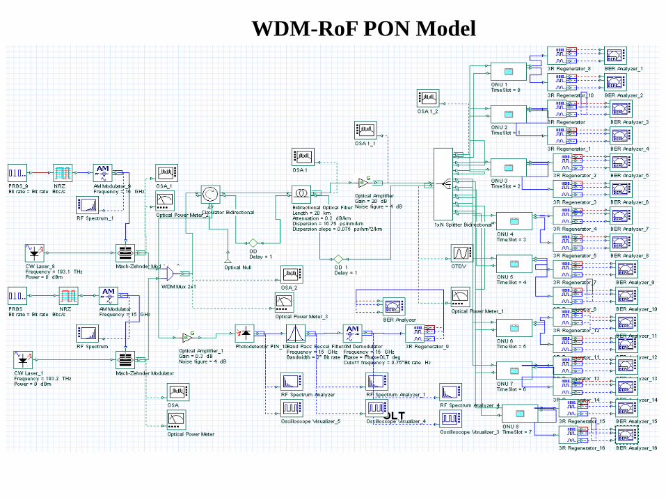
WDM-RoF PON Model

Design Inside ONU1 Subsystem

Parameter Value (IEEE 802.3 ah Standard)
Maximum downstream bit rate 1.25 Gbps
Maximum upstream bit rate 1.25 Gbps
Downstream Wavelength 1550 nm
Upstream Wavelength 1300 nm
Traffic Mode Ethernet
Modulation Format NRZ
OLT Power 0 dBm
ONU Power 0 dBm
Insertion Loss
(Circulator Bidirectional)
3 dB
Length
(Bidirectional Optical Fiber)
20 km
Dispersion
(Bidirectional Optical Fiber)
16.75 ps/nm/km
Dispersion Slope (Bidirectional Optical Fiber) 0.075 ps/nm2/km
Attenuation Constant
(Bidirectional Optical Fiber)
0.2 dB/km
Insertion Loss
( Bidirectional Splitter 1:8)
1.5 dB
Design Parameters

Results
First channel Radio frequency
at 15 GHz
First channel carrier frequency
at 193.1 THZ

Results
Second channel Radio
frequency at 15 GHz
Modulated Spectrum
after WDM-MUX
Second channel carrier
frequency at 193.2 THz
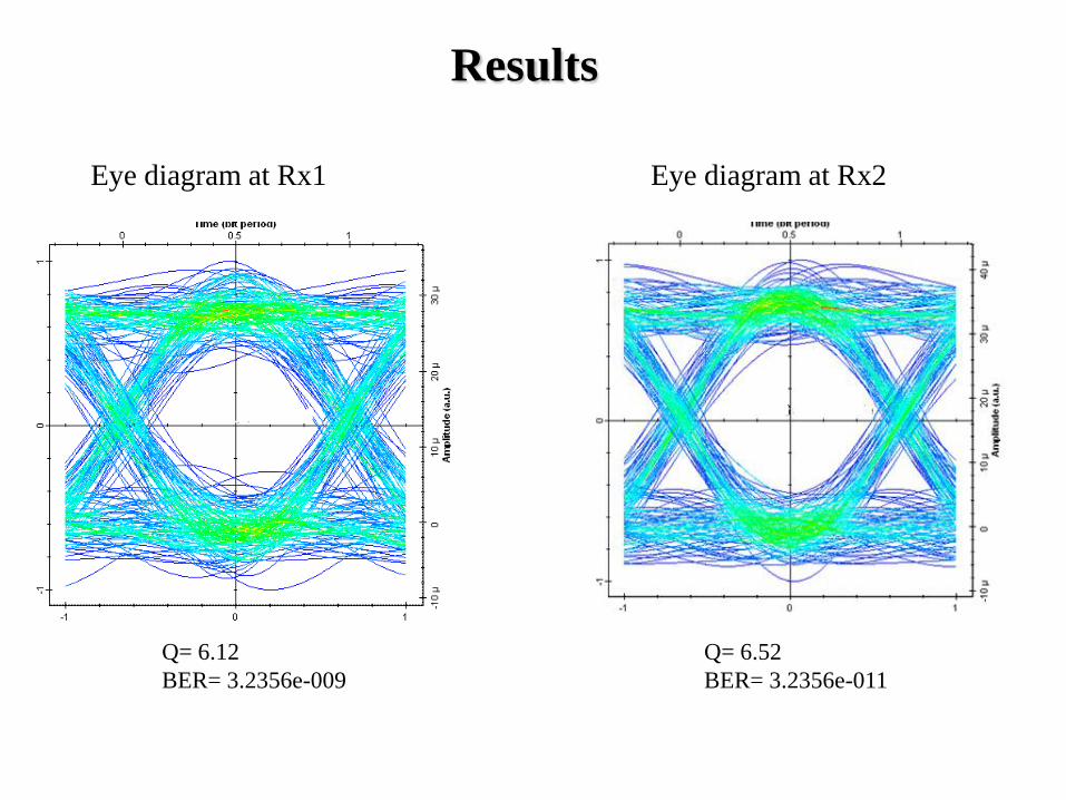
Eye diagram at Rx1 Eye diagram at Rx2
Results
Q= 6.12
BER= 3.2356e-009
Q= 6.52
BER= 3.2356e-011

Conclusion
• The simulation model for PON has been simulated by taking 20 km of
fiber length i.e. sufficient for different applications of this technology.
• It shows that various customer application requirements can be
satisfied and services can be prioritized and granted to the customers
and now it is easy for end users to get high data rates because of the
access bottleneck.
• The use of simulation helps us to focus on identifying the right design
and making decisions regarding how to deploy PON to address the
service needs without getting bogged down on a technology debate.
Performance enhancement with square
root module for WDM RoF-PON link

SQRT Filter Module (MATLAB Component)
In the design of WDM RoF-PON link, the optical receiver, receives the transmitted
signal and converts it back into electrical form and recovers the transmitted data.
At receiver side, PIN diode detector is used, which is a squaring device.
The PIN photodiode, when direct detecting the incoming optical power performs a
modulus square operation applied to the optical field.
IRX = Ein 2
where Ein is the input optical field envelope at the receiver
IRX is the detected electrical current
Hence, the whole system transfer function of an optical communication system is
made non-linear by the photodiode square law operation and the optical linear effects
generating Intersymbol Interference (lSI) are not linear any more.

A square root (SQRT) transfer function module (SRm) is proposed and placed after
the photodiode, compensates the square-law characteristic for improving the
performance of linear equalizers .
The SQRT filter is designed through MATLAB programming to see the performance
of WDM Transmission link
SQRT Filter Module (MATLAB Component)
SQRT filter at the receiver

MATLAB script
OutputPort1 = InputPort1;
if(outputPort1.TypeSignal==’Electrical’)
[LS,CS] = Size(InputPort1.Signal);
if(CS>0)
for counter1=1:CS
OutputPort1.Sampled(1,Counter1).Signal(1; :) =
sqrt(InputPort1.sampled(1,Counter1).signal(1,:));
end
end
end
SQRT Filter Module (MATLAB Component)
The MATLAB script which is used to interface MATLAB component with
simulation model has been described below.
In this script output and input ports of MATLAB component are defined as
electrical signals. The function LS and CS have been used to define input port for
optical or electrical signal. In case CS > 0 then input port is identified as electrical
port, and if LS > 0 then input port is optical port. Here CS > 0 is used to define
input as electrical in order to differentiate the electrical signal received from the
output of the PIN diode.

WDM PON model for radio frequency with SQRT Matlab
component

Design Inside ONU1 Subsystem Design Parameters
Parameter Value
Photo detector type PIN
Responsivity 1 A/W
Dark current 10 nA
Electrical filter type Band Pass RC filter
Bandwidth of electrical
filter
1.5 * bit rate Hz
Gain of electrical
amplifier
15 dB

Eye Diagram( At ONU_1 at 193.1 THz)
Q= 6.12
BER= 3.2356e-009
Q= 12.22
BER= 8.2356e-036
The improvement in the performance has been reported four times with the use
of SQRT Module at the receiver.

Eye Diagram( At ONU_1 at 193.2 THz)
Q= 7.52
BER= 3.2356e-012
Q= 14.84
BER= 3.2356e-048
The improvement in the performance has been reported four times with the use
of SQRT Module at the receiver.

Signal power with and without SRm
Receivers SNR with SRm ( dBm) SNR without SRm
( dBm)
ONU1 4.675 −20.563
OLT −47.118 −84.896
•The significant improvement in the signal power has been noticed which is
4.675, −47.118 dBm with SRm and −20.563, −84.896 dBm without SRm for
ONUs and OLT respectively.
•The BER patterns are showing improved performance with the use of SRm and
it is also observed in terms of signal power (compared before and after SRm).

Q factor vs. length
Q factor is maximum with SRm as compared to without SRm for different lengths
of fiber.

For Tx1, performance of the system is quite good even if input power is in the
range of −38 to 18 dBm with the use of SRm while this link is usable at input
power of −7 to 8 dBm without SRm similarly for Tx2, this range is −25 to 24
dBm with the use of SRm while this link is usable at input power of −6 to 15
dBm without SRm.
Q factor at Rx1 for different input
powers of Tx1 Q factor at Rx1 for different
input powers of Tx2
Conclusion
• In this simulation SRm is used at receiver side, which plays an
important role to enhance the performance of WDM-PON with RoF
technology.
• The improvement in the performance has been reported four times in
terms of BER for successful transmission over the distance of 20 km.
• Results are also compared for different fiber lengths and input powers
with and without SRm at the receiver and improvement in the
performance has been shown.

Performance enhancement with OSSB
transmission on WDM RoF-PON link

Why SSB Transmission?
• Fiber chromatic dispersion is one of the factors limiting transmission
distances in optical high-speed transmission systems.
• For a single mode laser, the symmetrical sidebands are created on the
optical carrier. Due to fiber chromatic dispersion, a relative phase shift is
added to these sidebands .
•Optical single sideband (OSSB) transmission is seen an excellent
method to overcome this problem. Dispersion effects can be reduced by
elimination of one sideband to produce an optical single-sideband (SSB).
•SSB technologies can suppress nonlinear optical effects because of the
reduced optical power to demonstrate the potential of modulators.

In this analysis ODSB signal is converted into OSSB through dual electrode MZM.
A CW signal from a laser with amplitude A and frequency fc is externally modulated
by an RF signal with amplitude Vac and frequency fm using the dual electrode MZM.
The RF signal is applied to both electrodes with π/2 phase shift applied to one
electrode. The output signal from the MZM is represented by
If the MZM is biased so that β=1/2 (i.e. at quadrature) and is driven such that α < 1/
π, equation 1 can be expanded using Bessel functions to
eq.1
eq.2
The Fourier transform of autocorrelation of gives the power spectrum
density SE(ω):
eq.3
The first term in equation 3 is the optical carrier while the second term represents
the lower sideband at the optical frequency ωc – ωm .
OSSB Generation

OSSB model for WDM–PON with radio frequency using SQRT
module

Generation of OSSB
To generate OSSB signal, input is applied to both the electrodes of Mach-
Zehnder modulator, in one electrode directly and another with π/2 phase shift.

Design inside first ONU1 Measurement blocks after ONU1
The received signal after WDM DEMUX is fed into a PIN photo-detector with
800 GHz sampling rate, responsivity of 0.6 A/W and a dark current of 1ηA.
After that band pass Bessel filter at 15 GHz frequency and 2.5 GHz bandwidth
and AM demodulator at 15 GHz frequency and 0.9375 GHz cut-off frequency
are selected for the electrical transmission. 3R regenerators and BER analyzers
are placed at receiver side to analyze the output .

(a) (b)
OSSB transmission spectrum (a) after Subsystem1(b) after WDM MUX
Optical SSB transmission with the suppression of 5 dB in the main carrier and 10
dB in the subcarrier is obtained. Further, performance of the system is enhanced
by using a SRm at receiver side to compensate the square-law characteristics of
photodiode.
Results
In downstream direction five channels 1552.5, 1551.72, 1550.91, 1550.11 and
1549.31 nm wavelengths with 0.8 nm spacing and 0 dBm power is combined
through WDM MUX and then transmitted via bidirectional optical fiber.

Results
Output at Rx1: (a) ODSB (b) OSSB without SRm (c) OSSB with SRm
BER= 4.2356e-027 BER= 6.4946e-054
For the successful transmission of OSSB, improvement in the performance in
terms of Q factor has been reported 67% as compared to ODSB and it is
further enhanced by 43% with the use of SRm.
(a) (b) (c)
BER= 3.2356e-009

53
Baljeet Kaur
The performance in the OSSB trans-mission link is quite good even if input
power is in the range of −55 to 28 dBm with the use of SRm while the link is
usable at input power of −12 to 26 dBm in case of without SRm.
Q factor versus input power for SSB with and without SRm
Analysis of results
Conclusion
• In this simulation, a technique for the generation of OSSB transmission
with carrier for WDM -PON with Radio over Fiber (RoF) optical link
is proposed.
• The suppression of 5 dB in carrier and 10 dB in the sidebands has been
shown.
• For the successful transmission of OSSB, improvement in the
performance in terms of Q factor has been reported 67% as compared
to ODSB and it is further enhanced by 43% with the use of SRm.
Related Publications
1. Performance enhancement with square root module for WDM RoF-EPON link, Baljeet Kaur,
Vinod Kapoor, Ajay K Sharma, Optik - International Journal for Light and Electron Optics, Volume
124, Issue 10, May 2012, Pages 967-971 (Impact Factor 0.526).
1. On WDM RoF–EPON link using OSSB transmission with and without square root module,
Baljeet Kaur, Vinod Kapoor, Ajay K Sharma, Optik - International Journal for Light and Electron
Optics, Volume 124, Issue 12, June 2012, Pages 1334-1337 (Impact Factor 0.526).
2. OVSB Generation on WDM RoF-EPON Link using SOA, Baljeet Kaur, Vinod Kapoor, Ajay K
Sharma, Int. J. Journal of information Processing, Accepted, Jan. 2013 (Impact Factor 0.152).
3. Performance Analysis of WDM RoF-EPON Link with and without DCF and FBG, Baljeet
Kaur, Vinod Kapoor, Ajay K Sharma, Int. J. Journal of Optics and Photonics Journal, OPJ,
Accepted, Feb. 2013 (Impact Factor 0.252).
4. On WDM RoF–EPON link using OSSB transmission with and without DCF and FBG, Baljeet
Kaur, Vinod Kapoor, Ajay K Sharma, Optik - International Journal for Light and Electron Optics,
Volume 125, 2014, pages 2066-2069 (Impact Factor 0.526).
5. Performance enhancement of WDM RoF-EPON Link with OVSB transmission using DCF
and FBG, Baljeet Kaur, Vinod Kapoor, Ajay K Sharma, Optik - International Journal for Light and
Electron Optics, Volume 125, 2014, pages 2062-2065 (Impact Factor 0.526).
6. A Simulation Study On WDM Rof-EPON Link In The Presence Of Four-Wave Mixing, V.
Kapoor, B. Kaur, and A. Sharma,, International Academic Conference, Las Vegas, pp. 259-264, Oct.
2011.
7. A Comparative Analysis of WDM RoF-EPON Link with and without DCF, V. Kumar, B. Kaur,
and A. K. Sharma,, International conference (ICMEME 2012), Bangkok, pp. 31-34, March 17-18,
2012.
REFERENCES...
• R. A. Grif_n, P. M. Lane, and J. J. O'Reilly, “Radio-Over Fiber Distribution Using an
Optical Millimeter – Wave / DWDM Overlay”, Proc. OFC/IOOC 99, vol. 2, pp. 70.72,
Feb. 1999.
• S. Shimotsu, S. Oikawa, T. Saitou, N. Mitsugi, K. Kubodera, T. Kawanishi, M. Izutsu,
LiNbO3 optical single-sideband modulator, in: OFC Conference, OSA, Paper PD-16,
March 7, 2000.
• A. Loayssa, D. Benito, M.J. Garde, Single-sideband suppressed – carrier modulation
using a single-electrode electo-optic modulator, IEEE Photon. Technol. Lett. 13 (August)
(2001) 869–971.
• G. P. Agrawal, "Nonlinear Fiber Optics, Second Edition” Academic Press, San Diego,
USA, Chap. 10, 2002.
• G. Kramer, G. Pesavento, Ethernet passive optical network (EPON): building a next-
generation optical access network, IEEE Commun. Mag. 40 February (2) 66–73, 2002.
• H. Toda, T. Yamashita, T. Kuri, and K. Kitayama, .Demultiplexing Using an Arrayed-
Waveguide Grating for Frequency-Interleaved DWDM Millimeter-Wave Radio-on-Fiber
Systems,. J. Lightwave Technol., vol. 21, no. 8, pp. 1735.1741, Aug. 2003.
• A. Banerjee, et al., Wavelength-division-multiplexed passive optical network (WDM-
PON) technologies for broadband access: a review, J. Opt. Netw. 4 (11) 737–758, 2005.
• H. Bong Kim and A. Wolisz, “A radio over fiber based wireless access network
architecture for rural area,” 14th IST Mobile and Wireless Commun. Summit, Dresden,
June 2005.

REFERENCES… • J. Prat, A. Napoli, J.M. Gene, M. Omelia, P. Poggiolini, V. Curri 2nd, Square root
strategy: a novel method to linearize an optical communication system with electronic
equalizers, in: Proc. ECOC, vol. 3, September pp. 713–714, 2005.
• J. Prat, M.C. Santos, M. Omella, Square root module to combat dispersion induced
nonlinear distortion in radio-over-fiber systems, IEEE Photon. Technol. Lett. 18
(September (18)) 1928–1930,2006 .
• J. Yu, Z. Jia, L. Xu, L. Chen, et al, “DWDM optical millimeter-wave generation for
radio-over-fiber using an optical phase modulator and an optical inter- leaver,” IEEE
Photon. Technol. Lett., vol. 18, no. 13pp. 1418-1420, 2006.
• T.G., Silveira, A.L.J., Teixeira, A.P.S. Ferreira, and P.M. N. P. Monteiro, “All-Optical
Vestigial Sideband Generation Using a Semiconductor Optical Amplifier”, IEEE Photonics
Technology Letters, vol. 18, No. 21, pp. 2212-2214, 2006 .
• An Vu Tran, Member, Ethernet PON or WDM PON: A Comparison of Cost and
Reliability, Department of Electrical and Electronic Engineering, The University of
Melbourne, 2007.
• G.K. Chang, J. Yu, and Z. Jia, “Architecture and Enabling Technologies for Super
Broadband Radio-over-Fiber Optical- Wireless Access Networks”, IEEE International
Conference, pp. 24 – 28 , MWP, Oct. 2007.
T.G., Silveira, A.L.J., Teixeira, A.P.S. Ferreira, and P.M. N. P. Monteiro, “All Optical
Vestigial Sideband Generation using counter propagating pumping in Semiconductor
Optical Amplifier”, The International Quantum electronics Conference, pp. 1,2007 .
• Abhinav Pratap Singh, Quality of service issues in WDM-EPON systems, in: IEEE
International Conference on Signal processing, Communications Networking, pp. 194–198,
2008.
• T.G., Silveira, A.L.J., Teixeira, A.P.S. Ferreira, and P.M. N. P. Monteiro, “All-optical
Conversion To Vestigial Sideband Through Self-Phase Modulation In Semiconductor
Optical Amplifier”, The International Conference on Transparent Optical Networks, pp. 1-4,
2009.
• Toshiaki Kuri, Member, IEEE, Hiroyuki Toda, Member, IEEE, Juan Jose Vegas Olmos,
Member, IEEE, and Ken-ichi Kitayama, Fellow, IEEE, “Reconfigurable Dense Wavelength-
Division-Multiplexing Millimeter-Waveband Radio-Over-Fiber Access System
Technologies”, Journal Of Lightwave Technology, Vol. 28, No. 16, pp. 2247-2257,August
15, 2010.
• Bo Xiang, “Application of Fiber Grating (FG) in Modern Optical Communications and
Beyond”, International J. of Advances in Optical Communication and Networks, vol. 1, No.
1, pp. 17-22, Dec. 2010.
• V. Kapoor, B. Kaur, and A. Sharma, " A Simulation Study On WDM Rof-EPON Link In
The Presence Of Four-Wave Mixing", International Academic Conference, Las Vegas, pp.
259-264, Oct. 2011.
• V. Kumar, B. Kaur, and A. K. Sharma, “A Comparative Analysis of WDM RoF-EPON Link
with and without DCF”, International conference (ICMEME 2012), Bangkok, pp. 31-34,
March 17-18, 2012.
REFERENCES

THANK You