of QUALIFICATION CARD GUIDE BOOK...
92
WIPP OPERATIONS FACILITY OPERATIONS WATCHSTATION QUALIFICATION CARD GUIDE BOOK (RCRA RELATED QUALIFICATION) FO-GUIDE-1 FO-GUIDE-1 Rev. 11 Page 1 of 91 APPROVAL: FORMAT: This Qualification Card Guide book has been reviewed and meets the content requirements for qualification and requalification as Facility Operations Shift Engineer (Surface), Central Monitoring Room Operator, and Facility Operations Roving Watch. This Qualification Card Guide Book is approved for use. Facility This Qualification Card Guide Book has been reviewed and meets format requirements in _ ._ rL -z-r-t::J Training Manager Date
Transcript of of QUALIFICATION CARD GUIDE BOOK...

WIPP OPERATIONSFACILITY OPERATIONS WATCHSTATIONQUALIFICATION CARD GUIDE BOOK(RCRA RELATED QUALIFICATION)
FO-GUIDE-1
FO-GUIDE-1 Rev. 11Page 1 of 91
APPROVAL:
FORMAT:
This Qualification Card Guide book has been reviewed and meets the contentrequirements for qualification and requalification as Facility Operations ShiftEngineer (Surface), Central Monitoring Room Operator, and Facility OperationsRoving Watch. This Qualification Card Guide Book is approved for use.
~~.Facility~ager
This Qualification Card Guide Book has been reviewed and meets format
requirements in~~ _ ._ ~
rL ~ -z-r-t::J ~Training Manager Date
FO-GUIDE-1 Rev.11Page 2 of91
Table of Contents
QUALIFICATION REQUIREMENTS 6
PART 1 - General Requirements ,. 6PART 2 - Practical Factor Performance " 7PART 3 - Modifications to Training Programs 8PART 4 - Qualification Program Format and Requirements 9PART 5 - Revisions to Qualification Programs During Initial Qualification. . . . . . . . . .. 10PART 6 - Re-qualification ,. . . . . . . . . . . . . . . .. 10PART 7 - Qualification Limit.. 11
'PART 8 - Entry Level Requirements 11
I. REFERENCES : . . . . . . . . . . . . . . . . . . . . . .. . . . . . . . . . . . . . . . . . . .. 12
A. HVAC 13B. High Voltage Electrical 15C. Low Voltage Electrical , . . . . . . . . . . . . . . . . . . . . . . . . . . . . . . . . . . . . .. 16D. Underground Ventilation/Filtration. . . . . . . . . . . . . . . . . . . . . . . . . . . . . . . . . . .. 17E. Fire Detection, Fire Suppression and Domestic Water. . . . . . . . . . . . . . . . . . .. 18F. Compressed Air 19G. ChilledWater 20H. 'Central Monitoring System 21I. Waste Water Treatment System 22J' Surface Fuel Station 23K. Vacuum 23L. Underground Electrical System 24M. Underground Ventilation System 251\1. WIPP System Information Manuals, Procedures & Instructions 26
II. CLASSROOM INSTRUCTION 30
III. SYSTEM KNOWLEDGE REQUIREMENTS - ROVING WATCH 31A. HVAC .... '.. . . . .. . . . . .. . .. . .. . . . . . . . . . . . .. . . . . . . . .. . . . . . . . . . . .. 31B. High Voltage Electrical 44C. Low Voltage Electrical 47D. Underground Ventilation/Filtration 48E. Fire Detection, Fire Suppression and Domestic Water 49F. Compressed Air 51G. Chilled Water 53H. Central Monitoring System 56I. Waste Water Treatment 56
FO-GUIDE-1 Rev.11Page 3 of 91
J. Surface Fuel Station 57K. Plant Vacuum 58
IV. SYSTEM OPERATION PRACTICAL EVALUATION - ROVING WATCH 62
A. HVAC 62B. High Voltage Electrical 64C. Low Voltage Electrical . . . . . . . . . . . . . . . . . . . . . . . . . . . . . . . . . . . . . . . . . . . .. 65D. Underground Ventilation and Filtration 66E. Fire Detection, Fire Suppression and Domestic Water. . . . . . . . . . . . . . . . . . .. 66F. Compressed Air 68G. Chilled Water 68H. Central Monitoring System 69I. Waste Water Treatment System 69J. Surface Fuel Station 69K. Plant Vacuum 69
V. ADMINISTRATIVE REQUIREMENTS - ROVING WATCH 73
A. Equipment Tagout/Lockout . . . . . . . . . . . . . . . . . . . . . . . . . . . . . . . . . . . . . . . .. 73B. Temporary Plant Modification. . . . . . . . . . . . . . . . . . . . . . . . . . . . . . . . . . . . . .. 73C. Work Authorization 74D. Conduct of Operations 74E. Control of Operator Aids .. . . . . . . . . . . . . . . . . . . . . . . . . . . . . . . . . . . . . . . . .. 75F. Facility Emergencies. . . . . . . . . . . . . . . . . . . . . . . . . . . . . . . . . . . . . . . . . . . . .. 76G. System Lineups. . . . . . . . . . . .. . . . . . .. . . . . . . . . . . . . . . . . . . . . . . . . . . . . .. 76H. Technical Safety Requirements 76I. Guidelines for Operating Electrical Components 77
VI. ADMINISTRATIVE REQUIREMENTS PRACTICAL EVALUATION - ROVING WATCH
A. Equipment Tagout/Lockout , 79B. Temporary Plant Modification 79C. Work Authorization 79D. System Lineups " 79
FO-GUIDE-1 Rev.11Page 4 of 91
III. SYSTEM KNOWLEDGE REQUIREMENTS - CMRO 59
A. CMS Equipment 59B. DTN Weather System 60C. Underground Electrical System. . . . . . . . . . . . . . . . . . . . .. . . . . . . . . . . . . . . . .. 60D. Underground Ventilation System 61
IV. SYSTEM OPERATION PRACTICAL EVALUATION - CMRO , 70
A. CMS Equipment Operation 70
V. ADMINISTRATIVE REQUIREMENTS - CMRO 78
> A.B.C.D.
CMS Alarm Enable/Disable Authorization . . . . . . . . . . . . . . . . . . . . . . . . . . . . . .. 78Facility Emergencies . . . . . . . . . . . . . . . . . . . . . . . . . . . . . . . . . . . . . . .. . . . . . .. 78Waste Handling Operations 7.8Mode Compliance, 78
VI. ADMINISTRATIVE REQUIREMENTS PRACTICAL EVALUATION - CMRO 80
A. Alarm Enable/Disable 80B. Facility Emergencies 80C. Waste Handling Operations 81D. Mode Compliance 8j
V. ADMINISTRATIVE REQUIREMENTS - FACILITY OPERATIONS SHIFT ENGINEER(SlJRFACE) ... ". . . . . . . . . . . . . . . . . . . . . . . . . . . . . . . . . . . . . . . . . . . . . . . . . . . . . .. 82
A. Equipment TagoutlLockout ". . . . . . . . . . . . . . . . . . . . . .. 82B. Temporary Plant Modification Control . . . . . . . . . . . . . . . . . . . . . . . . . . . . . . . . .. 82C. Conduct of Operations 82D. Control of Operator Aids . . . . . . . . . . . . . . . . . . . . . . . . . . . . . . . . . . . . .. 83E. System Lineups . . . . . . . . . . . . . . . . . . . . . . . . . . . . . . . . . . . . . . . . . . . . . . . . . .. 83F. Work Authorization 83G. Facility Emergencies . . . . . . . . . . . . . . . . . . . • . . . . . . . . . . . . . . . . . . . . . . . . . .. 84H. Miscellaneous Administrative Requirements 85I. Technical Safety Requirements 86
FO-GUIDE-1 Rev.11Page 5 of 91
VI. ADMINISTRATIVE REQUIREMENTS PRACTICAL EVALUATION - FACILITYOPERATIONS SHIFT ENGINEER (SURFACE) 88
A. Equipment TagoutiLockout . . . . . . . . . . . . . . . . . . . . . . . . . . . . . . . . . . . . . . . . .. 88B. Temporary Plant Modification 88C. Conduct of Operations 88D. Miscellaneous Administrative Tasks 88E. Work Authorization 89F. Facility Emergencies . . . . . . . . . . . . . . . . . . . . . . . . . . . . . . . . . . . . . . .. . . . . . .. 89G. Technical Safety Requirements 90
VII. WATCHSTANDING 91
Roving Watch 91Central Monitoring Room Operator 91Facility Operations Shift Engineer (Surface) 92
www-t M~ MY· p. WW-mMiW--W
QUALIFICATION REQUIREMENTS
'W
FO-GUIDE-1 Rev.11Page 6 of 91
PART 1 - GENERAL REQUIREMENTS:
This Qualification Card Guide Book is to be utilized by all Facility Operations Personnel qualifying asFacility Operations Shift Engineer (Surface), Central Monitoring Room Operator and FacilityOperations Roving Watch. Note, both the Facility Shift Manager and the Facility Operation ShiftEngineer (Surface) qualify under the FO-FOSE-3 (Surface) qualification card. This Qualification
.Card Guide Book represents the minimum knOWledge and competency requirements for INITIALAND BIENNIAL QUALIFICATION and REQUALIFICATION. All the requirements of the applicableinitial Qualification Card Signature Record Form must be completed by the candidate prior tooperating any equipment or performing any operating evolutions without the direct supervision of aqualified operator.
Training requirements should be conducted and signed by individuals who are qualified or appointedto the level required on the signature block contained in the Qualification Card Signature RecordForm. These include, but are not limited to:
ON-THE-JOB TRAINING EVALUATOR (OJTE): - Aqualified operator who has satisfactorilycompleted an oral examination on the performance of on-the-job training.
SUBJECT MATTER EXPERT (SME) - A qualified operator who has been designated by letter andsatisfactorily completed an oral examination on the designated system or equipment and theperformance of on-the-job training. Operators qualified as SME may also sign an OJTE trainingrequirement.
CENTRAL MONITORING ROOM OPERATOR (CMRO) - Any individual qualified to operate thesystems contained in the Central Monitoring Room.
FACILITY SHIFT MANAGER (FSM) - Any crew manager or shift engineer who has beendesignated as a Facility Shift Manager.
CREW MANAGER - The member of management appointed to manage a Facility Operations crew.This individual will normally be a Facility Shift Manager.
FACILITY OPERATIONS MANAGER (FOM) - The member of management appointed to direct theFacility Operations section.
PROFICIENCY QUALIFICATION REQUIREMENTS - The Facility Operations engineer shall berequired to stand watch as a Facility Shift Manager once per quarter to maintain the qualification of .Facility Shift Engineer. Documentation to meet this requirement will be as followed:
t
FO-GUIDE-1 Rev.11Page 7 of 91
• E-mail sent to Technical Training confirming a watch was performed as Facility Shift Manager.
• Forward a copy of the log for that shift to Technical Training annotating the Facility ShiftEngineer performed the watch as the Facility Shift Manager.
FO-GUIDE-1 Rev.11Page 8 of91
PART 2 - PRACTICAL FACTOR PERFORMANCE
All practical requirements should be completed to the indicated level of performance. Levels ofperformance are as follows:
PERFORM (P) - All aspects of the practical requirement will be performed in accordance with thedesignated procedure(s).
SIMULATE (S) - The practical requirement should be walked through in the field using the procedureand discussing the desired reaction and indication(s) expected as would be seen if the procedurewere being performed.
OBSERVE (0) - The candidate should watch all aspects of the requirement being performed by aqualified operator discussing the desired reaction(s) and indication(s) as they are observed.
DISCUSS (D) - The candidate should discuss all aspects of the requirement including desiredreaction(s) and indication(s). A discuss may be completed in a training area.
Where multiple levels of performance are indicated for a practical requirement, the goal of thecandidate and evaluator is to complete the highest level possible. The level achieved may be limitedby equipment status, facility conditions, or compliance modes. The hierarchy of levels ofperformance, from highest to lowest, are perform, simulate, observe, discuss. The evaluator willcircle the level of performance achieved on the practical requirement.
If the indicated level of performance for a requirement cannot be achieved, the highest levelachievable should be indicated. The Facility Operations Manager or designated alternate willapprove the change and initial, date, and note the reason the level of performance cannot beachieved. .

FO-GUIDE-1 Rev.11Page 9 of91
PART 3 • MODIFICATIONS TO TRAINING PROGRAMS
If a requirement must be deleted, the cognizant manager will draw a single line through the item, initialand date the deletion, provide a brief explanation for the deletion, and sign the deleted item. Thecognizant manager will notify Technical Training immediately after deleting an item so a revision canbe initiated. The Facility Operations Manager has the authority to delete requirements in anyqualification program based on facility status or condition during the time of the candidate'squalification program, or due to previous qualifications or qualifications achieved by the candidate.Requirements not completed at the time of qualification due to plant status will be completed as soonas status allows. The candidate will show "Provisional Qualification" status until all requirements aremet.
If a training requirement cannot be completed exactly as specified within this guide or theQualification Card Signature Record Form (this will usually happen only due to the superseding of aprocedure or by the significant modification of an item of equipment), the responsible individual(SME,O..ITE, FSM, etc.) shall annotate in the right-hand margin or at the bottom of the applicablepage on the_Qualification Card Signature Record Form how the requirement was completed (Le.,new procedure number) and sign/date the requirement in the Qualification Card. The FacilityOperations,Manager or designated alternate will approve the change and initial & date the entry priorto the candidate's final oral qualification board.
If the Facility Operations Shift Engineer (Surface) candidate is currently qualified as a FacilityOperations Roving Watch and Central Monitoring Room Operator, only the Qualification CardSignature Record Form FO-FOSE-3 must be completed. Facility Operations Shift Engineer(Surface) candidates not qualified as Facility Operations Roving Watch and Central MonitoringRoom Operator must complete all the sections of FO-RW-1 and FO-CMRO-2 Qualification CardSignature Records Forms as identified in the Qualification Card Signature Record Form FO-FOSE~,except Watchstanding Requirements. Facility Operations Shift Engineer (Surface) candidatesare only required to complete watchstanding requirements as listed in the FO-FOSE-3 QualificationCard Signature Record Form, regardless of the number ofprior qualifications held. CognizantCrew Managers retain the authority to require any Facility Operations Shift Engineer (Surface)candidate assigned to their respective shift crew to fully complete all subordinate watchstationqualification programs (including reqUired watches and qualification boards) enroute to fullqualification as Facility Operations Shift Engineer (Surface).
FO-GUIDE-1 Rev.11Page 10 of 91
PART 4 - QUALIFICATION PROGRAM FORMAT AND REQUIREMENTS
This Qualification Card Guide Book is divided into the following sections:
I. Qualification Requirements and ReferencesII. Classroom RequirementsIII. System Knowledge Requirements.IV. System Operation Practical Evaluation RequirementsV. Administrative RequirementsVI. Administrative Requirements Practical EvaluationVII. Watchstanding
The following rules apply for personnel in initial qualification only:
1. Classroom Requirements may be completed at any time prior to qualification on a particularwatchstation.
2. System Knowledge Requirements must be complete prior to the candidate working onAdministrative Requirements or Administrative Requirements Practical Evaluation.Verification of this requirement will be by FOM or FSM signature in the applicableQualification Card Signature Record Form.
3. . Candidates may complete Administrative Requirements and Practical Evaluation prior tocompleting all System Operation Practical Evaluation Requirements, butonly after all SystemKnowledge Requirements are completed.
4. Prior to the candidate working on the System Operation Practical Evaluation Requirements fora specific system, all knowledge requirements for that system must be completed.Completion of system practical factor requirements should be entered into the CMROlogbook. The log entry should include the reason for performance and trainee's name.
5. Prior to the candidate working on the Administrative Requirements Practical Evaluation for aspecific topic, all knowledge requirements for that topic must be completed.
Where two or more training watches are required for a particular shift on a particular watchstationprior to qualification, one watch per shift may be stood as an observation watch under instructionprior to the candidate's completing all System Knowledge Requirements for that watchstation. Allremaining "credit" watches shall be stood under instruction following completion of all SystemKnowledge Requirements requirements for that particular watchstation. Where required by aqualification program, the final evaluated watch or any cross-crew under instruction watches shouldbe completed when all training requirements (except Classroom Requirements) have been satisfied.
For candidates qualifying as Facility Operations Shift Engineer (Surface), similar sections ofsubordinate cards (eg: FO-RW-1, FO-CMRO-2) may be performed concurrently. A candidate mustcomplete System Knowledge Requirements in all assigned cards, however prior to working on anyIntegrated Plant requirements.

FO-GUIDE-1 Rev.11Page 11 of 91
The Facility Operations Shift Engineer (Surface) Qualification Card Signature Record (FO-FOSE-3)contains the qualification requirements for FO-RW-1 (Facility Operations Roving Watch), FO-CMRO2 (Central Monitoring Room Operator), OPS-01 (LockoutlTagout Authorizing Supervisor), OPS-02(Temporary Plant Modification Authorizing Supervisor) and P-37 (Person-in-Charge). Uponcompletion of FO-FOSE-3, specific qualification for FO-RW-1, FO-CMRO-2, OPS-01, OPS-02 andP-37 will not be required.
The Facility Operations Roving Watch Qualification Card Signature Record (FO-RW-1) contains thequalification requirements for OPS-01T (LockoutlTagout Technician) and OPS-02T (Temporary PlantModification Technician). Upon completion of FO-RW-1, specific qualification for OPS-01T andOPS-02T will not be required.
The applicable Qualification Card Signature Records should be retained by the Facility Operationswatchstander candidate until completed. When completed, all forms must be routed to the TechnicalTraining Group for review and retention.
PART 5 - REVISIONS TO QUALIFICATION PROGRAMS DURING INITIAL QUALIFICATION
Revisions to Qualification Card Signature Record Forms or this Guide Book will be accomplished inaccordance with WTS Training Section requirements. Candidates holding superseded QualificationCard Signature Record Forms following a new revision must obtain a copy of the new revision assoon as possible. The Facility Operations Manager will evaluate the need and methods fortransferring of qualification signatures between new and superseded record forms. This methodshould be concurred with by the WTS Training Manager or designee and must show full compliancewith requirements contained in the most recent program revision.
PART 6 - REQUALIFICATION
The Facility Operations Shift Engineer (Surface) Requalification Card Signature Record Form (FOFOSE-3R) contains illl of the biennial requalification requirements for FO-FOSE-3 (FacilityOperations Shift Engineer (Surface», FO-CMRO-2 (Central Monitoring Room Operator), FO-RW-1(Facility Operations Roving Watch), OPS-01 (LockouUTagout Authorizing Supervisor), OPS-02(Temporary Plant Modification Authorizing Supervisor) and P-37 (Person-in-Charge).
The Central Monitoring Room Operator Requalification Card Signature Record Form (FO-CMRO-2)contains all of the biennial requalification requirements for FO-CMRO-2 (Central Monitoring RoomOperator), FO-RW-1 (Facility Operations Roving Watch), OPS-01T (LockoutlTagout Technician) andOPS-02T (Temporary Plant Modification Technician).
The Facility Operations Roving Watch Requalification Card Signature Record Form (FO-RW-1 R)contains ml the biennial requalification requirements for FO-RW-1 (Facility Operations RovingWatch), OPS-01T (LockoutlTagout Technician) and OPS-02T (Temporary Plant ModificationTechnician).
FO-GUIDE-1 Rev.11Page 12 of 91
Watchstander qualification on system upgrades, enhancements or modifications that occursubsequent to initial qualification will be addressed and handled in a manner to be determined by theFacility Operations Manager and concurred with by the Manager of the Technical Training Section.
PART 7 • QUALIFICATION LIMIT:
The qualifications contained in this Qualification program are valid for two years. Extension ofqualification is achieved by timely completion of requalification cards FO-RW-1 R, FO-CMRO-2R, orFO-FOSE-3R as applicable.
The failure of any qualified operator to complete requalification within two years shall result in fulldisqualification from watchstanding duties until requirements are satisfied. The procedure toreestablish watchstander qualification shall be determined by the Facility Operations Manager inaccordance with WP 14-TR.01, WIPP Training Program, and concurred with by the Manager of theTechnical Training Section.
Notification or discovery of a failure of any qualified operator to meet specified periodic refreshertraining requirements related to the classroom requirements listed in Section II of this manual willresult in disqualification from watchstanding duties as defined in Section 17 of WP 14-TR.01.
PART 8 • ENTRY LEVEL REQUIREMENTS:
F.acility Operations Shift Engineer (Surface) candidates must be recommended by the FacilityOperations Manager for qualification as Facility Operations Shift Engineer (Surface) to includeTagoutlLockout Authorizing Supervisor, Temporary Plant Modification Cognizant OperationsSupervisor and Person-in-Charge. Validation of this recommendation is by FOM signature inQualification Card Signature Record Form FO-FOSE-3.
CMRO candidates must have current Roving Watch qualification in accordance with FO-RW-1except for Facility Operations Shift Engineer (Surface) candidates. Validation of this qualification isby FSM or FOM signature in Qualification Card Signature Record Form FO-CMRO-2.
FO-GUIDE-1 Rev.11Page 13 of 91
I. REFERENCES. . . . . . . . . . . . . . . . . . . . . . . . . . . . . . . . . . . . . . . . . . . . . . . . . . . . . . .. 13A. HVAC " " 13B. High Voltage Electrical 15C. Low Voltage Electrical 16D. Underground Ventilation/Filtration , 17E. Fire Detection, Fire Suppression and Domestic Water 18F. Compressed Air 19G. Chilled Water 20H. Central Monitoring System 21I. Waste Water Treatment System , 22J. Surface Fuel Station 23K. Vacuum 23L. Underground Electrical System. . . . . . . . . . . . . . . . . . . . . . . . . . . . . . . . . . . . . .. 24M, Underground Ventilation System. . . . . . . . . . . . . . . . . . . . . . . . . . . . . . . . . . . . .. 25N. WIPP System Information Manuals, Procedures & Instructions , 26

r" !C'"
FO-GUIDE-1 Rev.11Page 14 of 91
II. REFERENCESA. HVAC
Vendor Manuals
1. Moore Instruments Application Manual
WIPP Drawings
2. 41-B-003-W1, Exhaust Filter Building 413 HVAC System Piping and InstrumentDiagram.
3. 41-B-051-W, WasteHandling BUilding 411 RH Area HVAC - Piping andInstrument Diagram.
4. 41-B-066-W, TRUPACT Maintenance Facility 412 HVAC System Piping andInstrument Diagram.
5. 41-F-052-W1, Waste Handling Building 411 CH Area HVAC - AHU 41-B-812and 41-B-813 Piping and Instrument Diagram.
6. 41-F-052-W2, Waste Handling Building 411 CH Area HVAC - Exhaust Fans41-B-816,817, 835, 836 Piping and InstrumentDiagram.
7. 41-H-151-014, Waste Handling Building 411 RH Area HVAC Control LogicDiagram Sheet 1 of 2.
8. Waste Handling Building 411 CH Area HVAC Control Logic DOC System9. 41-H-158-014, Waste Handling Building 411 RH Area HVAC Control Logic
Diagram Sheet 2 of 2.10. Waste Handling Building 411 CH Area HVAC Control Logic DOC System.11. 41-H-163-014, Waste Handling Building 411 Mechanical Equipment Room
HVAC Control Logic Diagram.12. 41-H-166-W, TRUPACT Facility 412, HVAC System Control Logic Diagram.13. 41-H.,.167-W, Exhaust Filter Building 413, HVAC System Control Logic
Diagram.14. 41-H-351-014, Waste Handling Building 411 RH & CH Areas HVAC Instrument
Loop Diagram.15. 41-H-352-014, Waste Handling Building 411 RH & CH Areas HVAC Instrument
Loop Diagram.16. 41-H-370-W, Exhaust Filter Building 413 HVAC System Instrument Loop
Diagram.17. 45-B-009-W1, Building 486 HVAC Piping and Instrument Diagram.18. 45-B-009-W2, Building 486 AHUs 45-B-417,418, 419 &420.19. 45-F-020-008, HVAC System - Air Flow Diagram.20. 45-F-051-W, Support Building 451 Administrative Area Zone 1 HVAC Piping
and Instrument Diagram.21. 45-F-052-W, Support Building 451 Locker Room Zone 3 Area HVAC Piping
and Instrument Diagram.22. 45-F-053-W, Support Building 451 Laboratory Area Zone 2 HVAC Piping and
Instrument Diagram.23. 45-F-054-W, Support Building 451 Administrative Area Zone 4 HVAC Piping
FO-GUIDE-1 Rev.11Page 15 of 91
and Instrument Diagram.24. 45-F-055-W, Support Building 451 Administrative Area Zone 5 HVAC Piping
and Instrument Diagram.25. 45-F-056-W, Support Building 451 CMR and Instrument Shop Zone 6 HVAC
Piping and Instrument Diagram.26. 45-F-057-W, Water Pumphouse 456 HVAC System Piping and Instrument
Diagram.27. 45-F-060-012, Guard and Security Building 485 HVAC Arrangement - Plan and
Sections, Sheet 1 of 2.28. 45-F-061-012, Guard and Security Building 485 HVAC Arrangement - Plan and
Sections, Sheet 2 of 2.29. 45-H-051-W1, Support Building 451 Administrative Area Zone 1 HVAC
Instrument Loop Diagrams.30. 45-H-051-W2, Support Building 451 Administrative Area Zone 1 HVAC
Instrument Loop Diagrams.31. 45-H-052-W1, Support Building 451 Locker Room Zone 3 Area HVAC
Instrument Loop Diagrams.32. 45-H-052-W2, Support Building 451 Locker Room Zone 3 Area HVAC
Instrument Loop Diagrams.33. 45-H-053-W1, Support Building 451 Laboratory Area Zone 2 HVAC Instrument
Loop Diagrams.34. 45-H-053-W2, Support Building451 Laboratory Area Zone 2 HVAC Instrument
Loop Diagrams.35. 45-H-054-W1, Support Building 451 Administrative Area Zone 4 HVAC
Instrument Loop Diagrams.36. 45-H-054-W2, Support Building 451 Administrative AreaZone 4 HVAC
Instrument Loop Diagrams.37. 45-H-055-W1, Support Building 451 Administrative Area Zone 5 HVAC
Instrument Loop Diagrams.38. 45-H-055-W2, Support Building 451 Administrative Area Zone 5 HVAC
Instrument Loop Diagrams.39. 45-H-056-W1, Support Building 451 CMR and Instrument Shop Zone 6 HVAC
Instrument Loop Diagrams.40. 45-H-056-W2, Support Building 451 CMR and Instrument Shop Zone 6 HVAC
Instrument Loop Diagrams.41. 45-H-056-W3, Support Building 451 CMR and Instrument Shop Zone 6 HVAC
Instrument Loop Diagrams.42. 45-H-057-W, WaterPumphouse 456 HVAC System Instrument Loop Diagram.43. Support Building 451 HVAC System - Control Logic Diagram, DOC System44. Support Building 451 HVAC System - Control Logic Diagram, DOC System45. Support Building 451 HVAC System - Control Logic Diagram, DOC System46. Support Building 451 HVAC System - Control Logic Diagram, DOC System47. 45-H-158-W, Guard and Security Building 458 HVAC Control Logic Diagram.48. 45-H-351-014, Support Building 451 HVAC System Loop Diagram.49. ACA 9484 M-3, Tenwerature Control.50. ACA 9492 M-1, HVAc Floor Plan - Bldg. 489.51. ACA 9492 M-2, Mechanical Control Diagram - Bldg. 489.
11.12.
13.
14.15.
16.
17.
18.
19.
20.21.22.
II
J
FO-GUIDE-1 Rev.11Page 16 of 91
52. CMA M-3, Safety and Emergency Building Ground and Second Floor HVACPlans.
53. CMA M-4, Safety and Emergency Building HVAC Equipment Schedule.
B. High Voltage Electrical
Vendor Manuals
1. Installation, Operation and Maintenance Manual for Static Trip III OvercurrentTrip Device, SG-3118-02.
2. Operations and Maintenance Manual for 3502,3512 and 3516 IndustrialEngine.
3. Magna One Generator Installation, Operation and Maintenance Manual.4. Beeman, Donald. Industrial Power Systems Handbook5. Croft, Terrell. American Electrician Handbook6. Siemens-Allis Installation, Operation, Maintenance Instructions, 5 kV & 15 kV
Metal Enclosed load Interrupter Switches SG3328.7. Westinghouse Instructions for Type WLI load Interrupter Switchgear 5.0 kV,
15.0 kV, 25.8 kV & 38.0 kV.8. Square D Company Power-Zone HVl load Interrupter Switchgear 5 kV to 38
kV.9. PCI Company, load Interrupter Switch, Operations Instructions for 15 kV LIS
PCU156 Model.10. Siemens Metal Clad Switchgear Type D (5 kV) and F (15 kV), Installation,
Operation, & Maintenance Instructions SG3178, or Siemens Vacuum CircuitBreakers Type FSVand MSV Operation & Maintenance Instructions SG-324801.Westinghouse Instructions for Porcel-Line Type DH-P Circuit Breakers.S&C Pad-Mounted Gear, Manual PMH Models Outdoor Distribution, .Operations Instructions Sheet 662-510.Siemens low Voltage Circuit Breakers Type Rl Instructions for Installation,Operation, Maintenance, Parts SG-3068-1.DeletedInstructions 1B-5000 Series P-5000 POWl-VAC Vacuum Circuit Breakers4.16 kV, 7.2kV & 13.8 kV Voltage Classes.Westinhouse Instructions for low Votage Power Circuit Breakers Types DSDSLInstructions 1B46000Series P-46000Class E Controllers with Drawout AirBreak Contractor 2.5, 5, and 7.2 kV Voltage Class.Westinghouse Installation, Operation, Maintenance Instructions, Type CVVoltage Relay.GE Instructions GEK-45375F Time Overcurrent Relays Types IFC51A & 51 B,IFC53A & 53B, IFC77A & 77B .Brown Boveri Electric Type GWM Ground Shield Ground Wire Monitoring Relay.Simplex load Bank Operations Manual25-J-015-W, Sheets 1 through 7, Yard Electrical, Area Sub 3 and On SitePower 480V SWGR 25P-SWG04/3, Electrical Diagram and Details.

FO-GUIDE-1 Rev.11Page 17 of 91
23. 25-J-019-W3, Surface Medium Voltage Switchgears Trip Unit Settings.
24. 25-J-020-W4, WIPP Site Primary Power One Line Diagram With Surface LowVoltage Interrupter Lineup.
25. 25-J-021-W2, Surface 480 Volt Switchgears Trip Unit Settings.26. 25-J-044-W, Plant Main Substation (25P-SWG15/1), Station Power Unit
Number Eight Three Line Schematic.27. 25-J-060-W, Area Substation Number 3, 480V SWGR 25P-SWG04/3
Schematic Diagram.28. 25-J-066-W, Yard Electrical Plant Substation 25P-SWG15/1, Single Line
Diagram and Schemes.29. 25-J-071-W1, Backup Diesel Generator #1 25P-E-503 Generator Control
Schematic.30. 25-J-072-W1, Backup Diesel Generator #2 25P-E-504 Generator Control
Schematic.31. 25-J-094-W1, Yard Electrical Load Bank System Single Line Diagrams32. EC08758, Installation of New WIPP Utility Substation
C. Low Voltage Electrical
Vendor Manuals
1. Deleted2. Deleted3. EPS-2000 50 to 125 kVA Uninterruptible Power Supply System Owner's
Manual
WIPP Drawings4. PS-1 (Surface) Panel Schedules5. PS-3 (Trailers) Panel Schedules6. 25-J-020-W4, WIPP Site Primary Power One Line Diagram With Surface Low
Voltage Interrupter Lineup.7. 41-J-510-W1, Exhaust Filter Building 413 480V MCC 41P-MCC04/7 Single
Line Diagram.8. 41-J-511-W1, Waste Handling Building 411 480V MCC 41 P-MCC04/1 Single
Line Diagram.9. 41-J-512-W1, Waste Handling Building 411 480V MCC 41P-MCC04/3 and
41 P-DP04/3 Single Line Diagram and Arrangement.10. 41-J-513-W1, Waste Handling Building 411 480V MCC 41 P-MCC04/5 Single
Line Diagram.11. 41-J-514-W1, Waste Handling Building 411 480V MCC 41 P-MCC04/6 Single
Line Diagram.12. 41-J-527-W1, Waste Handling Building 411 480V MCC 41P-MCC04/2 Single
Line Diagram.13. 45-J-008-W1 through W6, Yard Switchracks14. 45-J-51 0-W1, Support Building 451 480V MCC 45P-MCC04/4 Single Line
Diagram.15. 45-J-511-W1, Support Building 451 480V MCC 45P-MCC04/3 Single Line
.- i:C·' '"'- ," '1 -WNm'--Ma~ 't':!: f'rT '-eWt "fOMT 2 mm
FO-GUIDE-1 Rev.11Page 18 of 91
Diagram.16. 45-J-512-W1, 458 Guard and Security Building 480V MCC 45P-MCC04/5
Single Line Diagram.
17. 45-J-515-W1, Water Pumphouse 456 480V MCC 45P-MCC04/2 Single LineDiagram.
D. - Underground Ventilation/Filtration
Vendor Manuals
1. EVA Flow Devices (The Book of EVA).2. Large Induction Motors: Toshiba 0 & M Manual.2B Flosconic Application and Installation Manual
WIPP Drawings
3. 25-J-020-W, WIPP Site Primary Power Distribution.4. DELETE5. 41-G-284-019, UVFS Exhaust Duct/Piping Arrangement.6. 41-G-302-34B, UVFS Modifications.7. 41-H-307-34B, UVFS Instrument Loop Diagram.8. 41-J-007-W, UVFS Diagram and Location Plans.9. 41-J-008-W, UVFS Control Panel Details.10. 41-J-015-W, Component Layout for 413-CP-307-01.
E. Fire Detection, Fire Suppression and Domestic Water
Vendor Manuals
1. Detroit Diesel Operators Manual.2. Patterson Pumps Operations Manual.3. Moore Single Loop Digital Controller.4. Wallace & Tiernan Chlorine Residual Analyzer.5. Masoneilan 2100 Series Control Valves.6. General Controls Hydramotor Actuators.7. Chlorinators and Controls.8. Exidyne Chlorine Gas Detector.9. Material Safety Data Sheets.10. National Fire Protection Association Manual, Chapter 20.
WIPP Drawings11. 23-F-001-007, Water Pipeline System, Piping and Instrument Diagram.12. 24-C-047-W, Site Utilities Water Domestic13. 25-F·006-W, Yard Utilities, Water Supply System, Piping and Instrument
Diagram.14. 41-J-024-W1, Waste Handling Building, Fire Panel 411-FP-01301.15. 41-J-024-W2, Waste Handling Building, Fire Panel 411-FP-01301.

FO-GUIDE-1 Rev.11Page 19 of 91
16. 45-F-041-014, Utility Water Distribution System, Piping and InstrumentDiagram.
17. 45-G-701-006, Water Storage Tanks 25-D-001A and B.18. 45-H-1 08-01 O,Water Pumphouse, Fire Water Pumping System Control Logic
Diagram.19. 45-H-110-010, Water Pumphouse, Water Pumping System Control Logic
Diagram.20. 45-H-130-01 0, Water Pumphouse, Fire and Security Systems Control Logic
Diagram.21. 45-H-31 0-01 0, Yard Utility and Water Pumphouse, Domestic Water Pumping
System Instrument Loop Diagram.22. 45-J-029-W1, Support Building 451, Fire Panel 451-FP-01132.23. 45-J-029-W2, Support Building 451, Fire Panel 451-FP-01132.24. 45-J-047-W, Water Pumphouse 456, Water Pumping System Schematic
Diagram.25. 45-J-515-W, Water Pumphouse 456, 480V MCC 45P-MCC04/2, Single Line
Diagram and Arrangement.
F. Compressed Air
Vendor Manuals
1. Ingersoll-Rand XLE Air Compressors.2. Ingersoll-Rand Type 30 Air Compressors.3. Atlas-Copco GA200 Compressors.4. Curtis-Toledo Model ES-20 Air Compressor.5. Hankison Model DH-2100 Regenerative Desiccant Air Dryer.6. Deltech PS Series Heatless Compressed Air Dryer.7. AMLOC-DHA Regenerative Desiccant Air Dryer.
WIPP Drawings
8. PS-1 (Surface) Panel Schedules9. 25-D-002-W, North Compressor Building 485 Plan View & Equipment Layout.10. 41-F-037-W, Compressor Building 463, Compressed Air/Cooling Water
System Piping and Instrument Diagram.11. 41-J-013-W, Air Compressors 41-G-021 AlB Panels Schematic Diagrams and
Parts Location.12. 41-J-014-W, Component Layout, Wiring and Schematic Diagrams for Air
Compressors 41-G-022A1B, 45-G-400AlB and 45-G-403A1B.13. 41-J-51 O-W, Exhaust Filter Building 413, 480V MCC 41 P-MCC04/7 Single
Line Diagram.14. 41-J-512-W, Waste Handling Building 411, 480V MCC 41P-MCC04/3 Single
Line Diagram. .15. 41-J-513-W, Waste Handling Building 411, 480V MCC 41 P-MCC04/5 Single
Line Diagram.16. 41-P-001-W, Exhaust Filter Building 413, Compressed Air System Piping and
Instrument Diagram.

Pt@-tlft 'S'
FO-GUIDE-1 Rev.11Page 20 of 91
17. 41-P-002-W, Waste Handling Building 411, Compressed Air System Pipingand Instrument Diagram.
18. 45-J-048-W, Compressor Building 485, Electrical Plan.19. 45-J-091-W1, Building 485 Electrical Arrangement.20. 45-J-091-W2, Building 485 Wiring Diagram.21. 45-J-091-W3, Sequencer 45P-ES03/001 Service Diagram, Bldg 485
Compressors 45-G-030A & B.22. 45-J-099-W1, Wiring Diagram for Atlas-Copco Compressor 45-G-030A.23. 45-J-099-W2, Wiring Diagram for Atlas-Copco Compressor 45-G-030B.24. 45-J-510-W, Support Building 451, 480V MCC 45P-MCC04/4 Single Line
Diagram.25. 45-P-001-W, North Compressor Building 485, Compressed Air System, Piping
and Instrument Diagram.26. 45-P-002-W, Support Building 451, Compressed Air System Piping and
Instrument Diagram.27. 53-P-001-W, Sheet 5, Underground and Shafts Compressed Air System Piping
and Instrument Diagram.
G. Chilled Water
Vendor Manuals
1. The Refrigeration Cycle, TRANE Air Conditioning Clinic Booklet.2. Refrigera1ion System Components. TRANE Air Conditioning Clinic Booklet.3. Refrigeration Compressors, TRANE Air Conditioning Clinic Booklet.4. Centrifugal Water Chillers, TRANE Air Conditioning Clinic Booklet.5. TRANE Air Conditioning Manual, Chapter VI.6. TRANE Owner-Operator's Guide Air-Cooled Centravac, CVAC-M-1A.7. TRANE Air Cooled Centravac liquid Chillers Centrifugal, CVAC-UP-1.8. TRANE Air Cooled Centravac Liquid Chillers Centrifugal, CVAC-IN-1A.9. TRANE Operation and Maintenance Manual, CGAC-M-3A.10. Carrier Flotronic Reciprocating Liquid Chillers, 30GB040-070.
WIPP Drawings
11. 25-J-020-W4, WIPP ~ite Primary Power One Line Diagram With Surface LowVoltage Interrupter Lineup.
12. 41-B-066-W, TRUPACT Maintenance Facility 412 HVAC System P&ID, Sheet1
13. 41-F-038-014, Waste Handling Building, Chilled Water System, Flow Diagram,Sheet 1 of 2.
14. 41-F-039'-014, Waste Handling Building, Chilled Water System, Flow Diagram,Sheet20f 2.
15. 41-F-068-W, Waste Handling Building, Chilled Water System, Piping andInstrument Diagram, Sheet 1 of 2.
16. 41-F-069-W, Waste Handling Building, Chilled Water System, Piping andInstrument Diagram, Sheet 2 of 2.
17. 41-H-168-014, Chilled Water System, Control Logic Diagram.
FO-GUIDE-1 Rev.11Page 21 of 91
18. 41-H-368-014, Chilled Water System, Instrument Loop Diagram.19. 45-J-051-W3, Engineering Building 486, Receptacle and Power Arrangement.20. 45-J-054-W, Building 486 Power Distribution Riser and Single Line Diagrams.21. 45-J-055-W1, Building 486 HVAC Wiring Schematic Diagrams.22. 41-J-545-W, Water Chiller Area, Instrument Grounding, Power and Control Plan.23. CMA-486-M-4, HVAC Equipment Schedule
FO-GUIDE-1 Rev.11Page 22 of 91
H. Central Monitoring System
Vendor Manuals
1.2.3.
> 3.> 4.> 5.> 6.> 7.> 8.> 9.> 10.> 11.> 12.> 13.
14.
Best FC-5kVA UPS Operation and Maintenance ManualToshiba Uninterruptible Power System 1400 and 1400 Plus SeriesCustom Automation 0 & MDELETEDELETEDELETEDELETEDELETEDELETEDELETEDELETEDELETEDELETEDELETEDTN User's Manual.
WIPP Drawings
15. PS-1, Panel Schedules (Surface)16. 41-J-760-014, Waste Handling Building 411, Local Processing Unit Layout
Plan, Sheet 1 of 4.
I. Waste Water Treatment System
Vendor Manuals
1. Environmental Protection Agency Operations Manual, Stabilization Ponds(EPA-430/9-77-012).
2. Environmental Protection Agency Process Design Manual, Land Treatment ofMunicipal Wastewater.
3. Environmental Protection Agency Handbook, Septage Treatment and Disposal.4. Environmental Protection Agency Design Manual, Municipal Wastewater
Stabilization Ponds.5. Instruction Manual, Diamond Shamrock Wastewater Chlorinator.6. Red Valve Manual, Pinch Valves, Manufacturer's Manual.
WIPP Drawings
7. 24-C-045-W, WIPP Site Utilities, Sanitary Sewer.8. 24-C-072-010, Stabilization Lagoon Grading & Fencing Plan & Sections.9. 25-C-004-W, Stabilization Lagoon Added Evaporation Pond10. 25-C-020-01 0, Stabilization Lagoon Plan & Sections.11. 25~C-021-01 0, Stabilization Lagoon Sections & Details.12. 25-C-049-010, Yard Piping - Plant Site to Stabilization Lagoon Plan &Profile.

FO-GUIDE-1 Rev.11Page 23 of 91
13. 25-D-004-010, Yard Piping & Stabilization Lagoon Valve Pits, Plans, Sections& Details.
J. Surface Fuel Station
Vendor lVIanuals
1. EBW Inc., AUTO/STIK JR. Operation Instruction Manual.2. XERXES Inc., Underground Storage Tanks, Double Wall Tank Installation and
Warranty Manual3. Rizzo, Joyce, Underground Storage Tank Management: A Practical Guide,
Fourth Edition.4. American Petroleum Institute Recommended Practice Manual, Bulk Liquid
Stock Control at Retail Outlets.5. EIB-USTR-1 through 14, State of New Mexico Underground Storage Tank
Regulations.6. Material Safety Data Sheet 948, Unleaded Gasoline.7. Material Safety Data Sheet 274, #1 Diesel Fuel.
WIPP Drawings
8. 25-C-037-010, Vehicle Fuel Station Fuel Storage Tanks Plan, Sections &Details.
9. 25-F-040-W, Facility #480 Vehicle Fuel System Piping & Instrument Diagram.10. 25-G-1 01-W, Facility #480 Vehicle Fuel Station Piping Arrangement.
K. Vacuum
Vendor Manuals
1. Rietschle Operating Instructions (For Model VTB 250.)
WIPP Drawings
2. 41-F-030-W, Waste Handling and Support Building, Plant Vacuum System,Piping and Instrument Diagram.
3. 41-J-026-W1, Vacuum Pump Wiring Diagram & Schematics 41-G-050A, B, C, Plant Vacuum System 411-CP-029-06.
4. 41-J-026-W2, Vacuum Pump Wiring Diagram & Schematics 41-G-050A, B, C, Plant Vacuum System 411-CP-029-06.
5. 41-J-512-W, Waste Handling Building 411, 480V MCG 41 P-MCC04/3 and41 P-DP04/3 Single Line Diagram and Arrangement.
6. 41-J-514-W, Waste Handling Building 411, 480V MCC 41 P-MCC04/6 SingleLine Diagram and Arrangement.
7. DELETE
, . -*-
FO-GUIDE-1 Rev.11Page 21of91
L. Underground Electrical System
Vendor Manuals
1. Ensign-Hubbell Power Center O&M Manual2. Westinghouse Low-Voltage Power Circuit Breakers, Types OS & DSL3. Square 0 Mini-Power Center O&M4. Toshiba Model 1400 UPS O&M5. 1000 KVA Power Center O&M6. S&C Mini Rupter Switch O&M7. Cimco Overtemp Device O&M8. Line Power High & Low Voltage Couplers O&M
Other Manuals
9. 30 CFR Federal Metal and Nonmetallic Mine Safety and Health Regulations10. ANSI C37.2
WIPP Drawings
11. PS-2, Underground Panel Schedules.12. 25-J-019-W4, U/G Medium Voltage Switchgear Trip Unit Settings13. 25-J-020-W1, WIPP Site Primary Power Distribution - One Line Reference
Sheet14. 25-J-020-W2, WIPP Site Primary Power Distribution - One Line Diagram15. 25-J-020-W3, Operations Surface & Underground16. 25-J-020-W4, Operations/Surface with 480 VAC Loads17. 25-J-020-W5, Operations/Underground with 480 VAC Loads18. 25-J-020-W6, Fault Analysis and Protected Device Coordination·19. 25-J-020-W7, Selected Load System, Operations - Surface & Underground20. 25-J-020-W8, Selected Load System Load Flow & Voltage Drop Calculation
Fault Current Analysis21. 25-J-020-W9, WIPP FSARlSurface22. 25-J-020-W10, WIPP FSARlUnderground23. 53-J-009-W1, U/G 13.8kV & Low Voltage Cable Routing & Equipment
Locations24. 53-J-009-W2, U/G 13.8kV & Low Voltage Cable Routing & Equipment
Locations25. 53-J-009-W3, U/G 13.8kV & Low Voltage Cable Routing & Equipment
Locations26. 53-J-028-W1, U/G 480V Power Distribution from 53P-SWG15/2A & 2B, Single
Line Diagram for 53P-CB04/1 ,CB04/2, DP04/1 (A & B), 2, 3, 4, 21, -LP04/3, LP04/1 & -LP04/2
27. 53-J-028-W2, U/G 480V Power Distribution from 53P-SWG15/2A & 2B, SingleLine Diagram for 53P-CB04/1, CB04/2, DP04/1 (A & B), 2, 3, 4, 21, -LP04/3, LP04/1 & -LP04/253-J-028-W3, U/G 480V Power Distribution from 53P-SWG15/2A & 2B, SingleLine Diagram for 53P-CB04/1, CB04/2, DP04/1 (A &B), 2, 3, 4, 21, -LP04/3, -
FO-GUIDE-1 Rev.11Page 25 of91
LP04/1 & -LP04/2
3.
4.
5.
53-J-037-W, U/G Substation #4 Location Single Line Diagram & AlcovePlan & Details53-J-510-W, U/G Utilities Sub #1 & Distribution Panel 53P-DP04/7 &
53P-DP04/7 Single Line Diagram53-J-511-W, U/G Utilities Sub #1 & Distribution Panels 53P-DP04/11,04/8,04/10
M. Underground Ventilation System
Vendor Manuals
1. Davis Anemometer O&M Manual2. LY Series Instruction & Maintenance Manual (Limotorque Corporation, U/G
. Regulator Motors3. SS4 AAA Products O&M Manual (U/G Bulkheads)
Other Manuals
4. 30 CFR 57 Subpart G-Ventilation
WIPP Drawings
5. PS-2, Underground Panel Schedules6. 54-W-001-W, U/G Mine Ventilation System7. 54-W-002-W, U/G Ventilation Plan Waste Handling Mode8. 54-W-004-W, U/G Ventilation Plan - Filtration Mode9. 54-W-005-W, U/G Ventilation Plan Air Reversal Mode for Mining Area and/or
Salt Handling Shaft10. 54-W-006-W, U/G Ventilation Plan Air Reversal Mode for Experimental Area11. 54-W-007-W, U/G Ventilation Plan Air Reversal Mode for Air Intake Shaft
N. WIPP System Information Manuals, Procedures & Instructions
System Information Manuals
1. WP 04-CAOO, Compressed Air (SIM)2. WP 04-CWOO, Chilled Water System (SIM)3. WP 04-CMOO, Central Monitoring System (SIM).4. WP 04-EDOO, High Voltage Electrical (SIM)5. WP 04-FPOO, Fire Detection and Suppression (SIM)6. WP 04-EDOO, Low Voltage Electrical (SIM)7. WP 04-GC03, Wastewater Treatment System (SIM)8. WP 04-HV01, WHB HVAC System (SIM)9. WP 04-HV02, WHB HVAC System (81M)10. WP 04-HV03, Support Building HVAC System (SIM)11. WP 04-HV04, Exhaust Filter Building HVAC System (SIM)
FO-GUIDE-1 Rev.11Page 26 of 91
12. WP 04-HV05, Building 456 HVAC (SIM)13. WP 04-HV05, Emergency Safety and Health Building HVAC (SIM)14. WP 04-HV05, Warehouse Building 453 HVAC (SIM)15. WP 04-HV06, Auxiliary Warehouse and Vehicle Service Building HVAC (SIM)16. WP 04-HV06, Engineering Building HVAC (SIM)17. WP 04-HV06, Guard and Security Building 458 HVAC (SIM)18. WP 04-PVOO, Plant Vacuum System (SIM)19. WP 04-VUOO, Underground Ventilation and Filtration System (SIM)20. WP 04-WDOO, Water Distribution (WDOO)(SIM)21. Plant Monitoring and Communications (System Design Description
(SDD)(CMOO).22. U/G Ventilation System Design Description (SOD)23. U/G Ventilation and Filtration System Design Description (SOD)
WIPP Procedures
24. WP 02-6 & 7, Resource Conservation & Recovery Act (RCRA) ComplianceManual.
25. WP 02-12, WIPP Contingency Plan.26. WP 04-AD3001, Facility Mode Compliance.27. WP 04-AD3005, Administrative Control of System Lineups.28. WP 04-AD3007, CMS Point Scan/Alarm Check Removal Authorization.29. WP 04-AD3008, Shift Operating Logs.30. WP 04-AD3011, Equipment Tagout/Lockout.31. WP 04-AD3012, Temporary Plant Modification Control.32. WP 04-AD3027, TSR Violation Reporting and Recovery Plan.33. WP 04-CA1001, Operation ofAir Compressors 41-G-021A and 41-G-021B.34. WP 04-CA1003, Operation of Exhaust Filter Building and Support Building Air
Compressors.35. WP 04-CA1101, Instrument Air Operation.36. WP 04-CA1202, Operation of Air Compressors 45-G-030A & B.37. WP 04-CA4001, Compressed Air System Alarm Response.38. WP 04-CM1001, Remote Operation of the Diesel Generators.39. WP 04-CM1 006, Remote Operation of Electrical Circuit Breakers.
. 40. WP 04-CM1185, Remote Operation of the Support Building Zone 6 HEPAFiltration.
41. WP 04-CM1301, Public Address System Console Operation.42. WP 04-CM1303, Historical Storage & Retrieval Operation.43. WP 04-CM1304, CMS Equipment Operation.44. WP 04-CM1305, LPU Downloading.45. WP 04-CM1306, Operation of Remote Uninterruptible Power Supplies for CMS
Equipment.46. WP 04-CM4501, VOC Trouble Alarms.47. WP 04-CO, Conduct of Operations Manual48. WP 04-CW1101, Waste Handling Building (WHB) and Support Building (SB)
Chilled Water System.49. WP 04-CW41 01, WHB and SB Chilled Water System Alarm Response.50. WP 04-ED1 001, 13.8 kV Surface Transformer Operating Instructions.
FO-GUIDE-1 Rev.11Page 27 of91
51. WP 04-ED1 021, Site Surface Electrical Distribution System.52. WP 04-ED1301, Diesel Generator Operation53. WP 04-ED1341 , Surface Backup Power Distribution.54. WP 04-ED1542, Central Uninterruptible Power Supply Unit 2 45P-UPS03/2.55. WP 04-ED1621, Underground Electrical Distribution56. WP 04-ED1631, Underground Backup Power Distribution57. WP 04-ED2341, Remote Operation of Underground Circuit Breakers.58. WP 04-ED4301, Diesel Generators 1 and 2 Local Alarm Response.59. WP 04-EM4542, Central Uninterruptible Power Supply Unit 2 45P-UPS03/2
Alarm Response.60. WP 04-EM1301 , Seismic Monitoring System Operation.61. WP 04-EM1302, Quarterly Operational Test of Surface Seismic Monitoring
System.62. WP 04-FP1201, Site Fire Water Supply System Operation.63. WP 04~FP2201,Electric Fire Pump.64. WP 04-FP2202, Diesel Fire Pump.65. WP 04-GC1201 , Sewage Lagoon System Operation.66. WP 04-GC1605, Operation of Surface Fuel Station Storage Tanks.67. WP 04-H0401 0, Mine Hoist Emergency Responses68. WP 04-HV1001, Waste Handling Building Zone 1 HVAC.69. WP 04-HV1021 , Waste Handling Building Zone 2 HVAC.70. WP 04-HV1 041, Waste Handling Building Hoist Room and Waste Shaft Area
HVAC (Zone 3).71. WP 04-HV1061 , WHB RH Area HVAC (Zone 4).72. WP 04-HV1081,TRUPACT Maintenance Facility Building 412 HVAC.73. WP 04-HV1101, Support Building Zone 1 HVAC.74. WP 04-HV1116, Support Building Zone 2 HVAC.75. WP 04-HV1131, Support Building Zone 3 HVAC.76. WP 04-HV1146, Support Building Zone 4 HVAC.77. WP 04-HV1161 ,Support Building Zone 5 HVAC.78. WP 04-HV1176, Support Building Zone 6 HVAC.79. WP 04-HV1201, Exhaust Filter Building HVAC.80. WP 04-HV1301, Guard and Security Building HVAC System.81. WP 04-HV1306, Safety and Emergency Building HVAC.82. WP 04-HV1316, Engineering Building HVAC System Operation.83. WP 04-HV4021, HVAC Alarm Response.84. WP 04-MD3003, Control of Operator Aids.85. WP 04-PC3017, Essential Plant Communications Systems Testing.86. WP 04-PV1201 , Operation of Waste Handling Building and Support Building
Vacuum System.87. WP 04-VU1001, Surface UVFS Operation.88. WP 04-VU1002, Operability Testing of Underground Filtration.89. WP 04-VU1608, Underground UVFS Operation.90. WP 04-VU1610, Reentry91. WP 04-VU2603, UVFS Air Reversal for Non-RMA Areas92. WP 04-VU4605, UVFS Alarm Response.93. WP 04-WD1 01 0, Domestic Water System Operation.94. WP 04-WD1 020, Free Chlorine Analyzer Operation

·P-·t-"@¥ - r M xc 7 t emn".j
FO-GUIDE-1 Rev.11Page 28 of91
95. WP 04-WD401 0, Pumphouse Alarm Response.96. WP 04-CM1 002, Routine Operations for CMRO97. WP 04-CM2002, CMRO Actions for Transportation.98. WP 06-HM1 020, TRUPACT-II Receipt.99. WP 06-HM1040, Empty TRUPACT-II Receipt.100. WP 06-HM31 08, Request for Disposal.101. WP 06-HM31 09, Nonradioactive Satellite Waste Accumulation Area Inspection.102. WP 10-2, Maintenance Operations Instruction Manual103. WP 10-AD3005, Control and Use of Maintenance Locks.104. WP 10-WC3002, Work Control Administration.105. WP 10-WC3004, Preventive Maintenance Administration.106. > 09.DC.01, Surface Excavation and Backfill Permit.107. WP 12-1, WIPP Safety Manual108. WP 12-IH.02, Confined Space Entry Program.109. WP 12-FP3002, Hot Work Permits.110. WP 12-9, WIPP Emergency Management Plan.111. WP 02-AR1001, Unreviewed Safety Question Determination.112. WP 12-ER3903, Event Recovery113. WP 12-ER3904, Categorization and Classification of Operational
Emergencies.114. WP 12-ER4901, Severe Weather Response.115. WP 12-ER4902, Hazardous Material Spill Response.116. WP 12-ER4903, Radiological Event Response117. WP 12-ER4905, Security Emergency Response.118. WP 12-ER4906, Surface Medical Emergency.119. WP 12-ER4907, Site Evacuation..120. WP 12-ER4908, Surface Fire Response;121. WP 12-ER4910, Earthquake/Seismic Response.122. WP 12-ER4911, Underground Fire Response.123. WP 12-ER4912, Underground Medical Emergency Response.124. WP 12-ES3918, Reporting Occurrences in Accordance with DOE Order 232.1.125. WP 13-1, WID Quality Assurance Program Description.126. WP 13-QA3001, Hold Tag Issuance.127. MP1.2, Work Suspension and Stop Work128. WP 13-QA3003, Corrective Actions Program129. WP 14-TR.01, WIPP Training Program.130. WP 14-TR3307, Qualification Programs.131. WP 14-TR3308, On-the-Job Training.132. Waste Isolation Pilot Plant Mine Ventilation Plan
Facility Operations Instructions and Standing Instructions
133. Facility Operations Shift Instructions and Standing Instructions
Permits and Technical Safety Requirements
134. DOEIWIPP-91-005, Resource Conservation and Recovery Act Part B PermitApplication
FO-GUIDE-1 Rev.11Page 29 of 91
135. DOEIWIPP-95-2065, WIPP Safety Analysis Report136. DOEIWIPP-95-2125, WIPP Technical Safety Requirements
Miscellaneous
137. WP 05-WH1 011, CH Waste Processing138. WP 05-WH4401, Waste Handling Operator Event Response139. WP 04-ED2306, Powering Essential UPS Loads Via Power Conditioner140. WP 04-FP201 0, Alternate FW Supply Lineup141. UV-0281, Engineer Station Suport Utilities Document142. Genicom O&M Manual143. Site Phone Book144. CMR Fax Machine O&M Manual145. WP 09-CN3022, Engineering File Resources Operations146. Siemens MCC O&M Manual147. Drawing 45·B-050-W148. Drawing ACA 9492-M-3149. Drawing 45-J-005-W

FO-GUIDE-1 Rev.11Page 30 of 91
II. CLASSROOM INSTRUCTION
ROVING WATCH
A. Current Electrical Safety (ELC-1 03)
B. Current Subject Matter ExpertlOn-the-Job Training (TRG-293)
C. Conduct of Shift Operations (OPS-115)
D. Print Reading (PRT-103)
E. Current Radiological Worker I (RAD-1 01)
CMRO
A. Current Hazardous Materials Emergency Response (HMT-104)
FACILITY OPERATIONS SHIFT ENGINEER (SURFACE)
A. Root Cause Analysis (TRG-296)
B. WIPP Occurrence Reporting for FRfFRD/FM/FMD/FSM (OPS-11 0)
C. WIPP Contingency Plan Procedure (SAF-645)
D. Confined Space Entry (SAF-515) (Classroom Phase Only)
E. Current Hazardous Waste Worker (HWW-101 or HWW-102)
F. Incident Command Training

FO-GUIDE-1 Rev.11Page 31 of91
III. SYSTEM KNOWLEDGE REQUIREMENTS - ROVING WATCH
To complete the requirements in the Signature Record Form, theSI\IIE will certify, by oralexamination, that the candidate has adequate knowledge of the objectives listed below.
A. HVAC
1 Safety Building HVAC (Ref. A.52, A.53, N.13, N.82)
a. Discuss the following as they apply to the Safety Building HVAC:
• Component location and operation• Component TagoutlLockout locations• Applicable alarm responses• Operation of system controls including system timers and zone
thermostats
2. Pumphouse HVAC (Ref. A.26, A.42, N.12)
a. Discuss the following as they apply to the Pumphouse HVAC:
• Component location and operation• Component TagoutlLockout locations• Applicable alarm responses• Operation of system controls
3. Warehouse HVAC (Ref. A.19. N.14)
a. Discuss the following as they apply to the Warehouse HVAC:
• Component location and operation• Component TagoutlLockout locations• Applicable alarm responses• Operation of system controls
4. Guard and Security Building HVAC
a. Using the appropriate drawing, locate the major system components(Ref. A.27, A.28):
(1) Supply Fan 45-B-401
(2) Supply Fan 45-B-402
(3) Supply Fan 45-B-403
(4) Roof Exhaust Fan 45-B-409
(5) Booster Fan 45-B-410
"",q1_~ ~, ..._~-_R"_~~_-__rt __:~_ZP_1_"'5,__:?_d_~"_···.-. ._0.. __------5-------- _
FO-GUIDE-1 Rev.11Page 32 of91
(6) Temperature Transmitters
(7) Control Panel 459-CP-058-01
(8) Heat Pump 45-B-404
(9) Heat Pump 45-B-405
(10) Heat Pump 45-B-406
(11 ) Heat Pump 45-B-407
(12) Heat Pump 45-B-408
(13) Duct Heater 45-B-411
(14) Duct Heater 45-B-416
b. Discuss the following as they apply to the Guard and Security BuildingHVAC (Ref. A27, A28, A.47, N.17, N.81):
• Component operation• Component TagoutlLockout locations• Applicable alarm responses• Operation of system controls
c~ Discuss the control logic of the Guard and Security Building HVAC (Ref.A47).
5. Engineering Building HVAC
a. Using the appropriate drawing, locate the major system components(Ref. A17, AI8):
(1) Supply Fan 45-B-417
(2) Supply Fan 45-B-418
(3) Supply Fan 45-B-419
(4) Supply Fan 45-B-420
(5) Exhaust Fan 45-B-421
(6) Exhaust Fan 45-B-422
(7) Exhaust Fan 45-B-423

FO-GUIDE-1 Rev.11Page 33 of 91
(8) Exhaust Fan 45-B-424
(9) Exhaust Fan 45-B-425
(10) Exhaust Fan 45-B-426
(11) Exhaust Fan 45-B-427
(12) Exhaust Fan 45-B-428
(13) Control Panels
b. Discuss the following as they apply to the Engineering Building HVAC(Ref. AI7, A.18, N.16, N.83):
• Component operation• Component TagoutiLockout locations• Applicable alarm responses• Operation of system controls including system timers and zone
thermostats
c. Discuss the control logic of the Engineering Building HVAC (Ref. A17,A18, A49).
6. Training Building HVAC
b. Using the appropriate drawing, locate the major system components (RefA50):
(1) AHU 45-B-430
(2) AHU 45-B-431
(3) AHU 45-B-433
(4) AHU 45-B-434
(5) AHU 45-B-435
(6) AHU 45-B-436
(7) AHU 45-B-437
(8) AH U 45-B-438
(9) AHU 45-B-439
'ee- 1$ ;---- ,we "-_'f F_jl"_-,*"~\_--~'¥r1ij_"---?f ~_P-r:_"zrt
(10) Conpensing Unit 45-E-008II
(11 ) ConrenSing Unit 45-E-009
(12) Condensing Unit 45-E-01 0
(13) Condensing Unit 45-E-01
(14) Condensing Unit 45-E-012
(15) Condensing Unit 45-E-013
(16) Condensing Unit 45-E-014
(17) Condensing Unit 45-E-015
(18) Condensing Unit 45-E-016
(19) Room Thermostats
'tmn we-
FO-GUIDE-1 Rev.11Page 34 of91
b. Discuss the following as they apply to the Training Building HV AC (Ref.A.50, A.51):
• Component operation• Component TagoutlLockout locations• Applicable alarm responses• Operation of system controls
7. Exhaust Filter Building (EFB) HVAC
a. Using the appropriate drawing, locate the major system components(Ref. A.2, A.16):
(1 ) Supply Fan 41-B-870
(2) Supply Fan 41-8-871
(3) Exhaust Fan 41-8-881
(4) Exhaust Fan 41-8-882
(5) HEPA Filter 41-8-883
(6) HEPA Filter 41-8-884
(7) Temperature Transmitter
(8) AHU Heaters
FO-GUIDE-1 Rev.11Page 35 of 91
(9) Control Panel. 413-CP-067-02
(10) Control Panel 413-CP-067-05
b. Discuss the following as they apply to the Exhaust Filter Building HVAC(Ref. A.2, N.11, N.80, N.84):
• Component operation• Component Tagout/Lockout locations• Applicable alarm responses• Operation of system controls
c. Using the appropriate drawing, discuss the control logic of the ExhaustFilter Building HVAC (Ref. A.13).
d. Discuss the instrument loop for EFB HVAC (Ref. A.16)
8. Support Building HVAC - ZONE 1
a. Using the appropriate drawing, locate the major system components(Ref. A.20):
(1) Supply Fan 45-B-101
(2) Exhaust/Retum Fan 45-B-102
(3) Temperature Controllers
(4) Duct Heaters
(5) Control Panel 451-CP-051-33
(6) Chilled Water Temperature Control Valve
b. Discuss the following as they apply to the Support Building Zone 1 HVAC(Ref. A.20, N.10, N.74, N.84):
• Component operation• Component Tagout/Lockout locations• Applicable alarm responses• Operation of system controls
c. Using the appropriate drawing, discuss the control logic of the Zone 1HVAC (Ref. A.43).
d. Discuss the instrument loop for Zone 1 HVAC (Ref. A.29, A.30).
e. State the areas served by Zone 1 HVAC (Ref. A.20, N.10).
9. Support Building HVAC - ZONE 2

FO-GUIDE-1 Rev.11Page 36 of91
a. Using the appropriate drawing, locate the major system components(Ref. A.22):
b. Discuss the following as they apply to the Support Building Zone 2 HVAC(Ref. N.10, N.75, N.84):
• Component operation• Component Tagout/Lockout locations• Applicable alarm responses• Operation of system controls
c. Using the appropriate drawing, discuss control logic ofthe Zone 2 HVAC(Ref. A.44, A.48).
d. Discuss the instrument loop for Zone 2 HVAC(Ref. A.33, A.34).
e. State the areas served by Zone 2 HVAC (Ref. A.22, N.10).
10. Support Building HVAC - ZONE 3
FO-GUIDE-1 Rev.11Page 37 of91
• Component operation• Component Tagout/Lockout locations• Applicable alarm responses• Operation of system controls
c. Using the appropriate drawing, discuss the control logic of the Zone 3HVAC (Ref. A.45).
d. Discuss the instrument loop for Zone 3 HVAC (Ref. A.31, A.32).
e. State the areas served by Zone 3 HVAC (Ref. A21, N.1 0).
11. Support 8uilding HVAC - ZONE 4
a. Using the appropriate drawing, locate the major system components(Ref. A.23):
(1) Supply Fan 45-8-120
(2) Exhaust/Retum Fan 45-8-121
(3) Exhaust Fan 45-8-122
FO-GUIDE-'1 Rev.11Page 38 of91
(4) Temperature Controllers
(5) Duct Heaters
(6) Control Panel 451-CP-054-37
(7) Chilled Water Temperature Control Valve
b. Discuss the following as they apply to the Support Building Zone 4 HVAC(Ref. N.10, N.77, N.84):
• Component operation• Component Tagout/Lockout locations• Applicable alarm responses• Operation of system controls.
c. Using the appropriate drawing discuss the control logic of the Zone 4HVAC (Ref. A.46).
d. Discuss the instrument loop for Zone 4 HVAC (Ref. A.35, A.36).
e. State the areas served by Zone 4 HVAC (Ref. A.23. N.10).
12. Support Building HVAC ZONE 5
a. Using the appropriate drawing, locate the majorsystem components(Ref. A.24):
(1) Supply Fan 45-8-125
(2) ExhaustlReturn Fan 45-B-126
(3) Exhaust Fan 45-B-127
(4) Temperature Controllers
(5) Duct Heaters
(6) Control Panel 451-CP-055-38
(7) Chilled Water Temperature Control Valve
b. Discuss the following as they apply to the Support Building Zone 5 HVAC(Ref. N.10. N.78, N.84):

FO-GUIDE-1 Rev.11Page 39 of91
• Component operation• Component Tagout/Lockout locations• Applicable alarm responses• Operation of system controls
c. Using the appropriate drawing, discuss the control logic of the Zone 5HVAC (Ref. A.46).
d. Discuss the instrument loop for Zone 5 HVAC (Ref. A.37. A.38).
e. State the areas served by Zone 5 HVAC (Ref. A.24, N.10)
13. Support Building HVAC - ZONE 6
a. Using the appropriate drawing, locate the major system components(Ref. A.25):
(1 ) Supply Fan 45-B-130
(2) Supply Fan 45-B-131
(3) Booster Fan 45-B-135
(4) Condensing Unit 45-B-132
(5) Condensing Unit 45-B-133
(6) Exhaust Fan 45-B-136
(7) Exhaust Fan 45-B-137
(8) Temperature Controllers
(9) Duct Heaters
(10) Control Panel 451-CP-056-36
(11 ) Differential Pressure Transminers
b. Discuss the following as they apply to the Support Building Zone 6 HVAC(Ref. N.10, N.79, N.84):
• Component operation• Component Tagout/Lockout locations.- Applicable alarm responses• Operation of system controls
c. Using the appropriate drawing, discuss the control logic of the Zone 6HVAC (Ref. A.46).
FO-GUIDE-1 Rev.11Page 40 of 91
d. Discuss the instrument loop for Zone 6 HVAC (Ref. A.39, AAO, AA1).
e. State the areas served by Zone 6 HVAC (Ref. A.25, N.10)
14. Waste Handling Building HVAC - ZONE 1
a. Using the appropriate drawing, locate the major system components(Ref. A.5, A.6):
(1 ) Supply Fan 41-B-861
(2) Supply Fan 41-B-863
(3) Exhaust Damper 411-HD-063-08
(4) Exhaust Damper 411-HD-063-11
(5) Exhaust Damper 411-HD-063-12
(6) Exhaust Damper 411-HD-063-13
(7) Temperature Transmitters
(8) Unit Heaters41-B-904 through 41-B-908
(9) Control Panel 411-CP-063-16
(10) KURZ PaneI411-CP-063-16A
(11 ) Chilled Water Temperature Control Valve
b. Discuss the following as they apply to the Waste Handling Building Zone1 HVAC (Ref. N.8, N.69, N.84):
• Component operation• Component TagoutlLockout locations• Applicable alarm responses• Operation of system controls• DDC System
c. Using the appropriate drawing, discuss the control logic of the Zone IHVAC (Ref. A.11).
d. State the areas served by Zone 1 HVAC (Ref. A.5, A.6. N.8)
15. Waste Handling Building HVAC - ZONE 2
FO-GUIDE-1 Rev.11Page 41 of91
a Using the appropriate drawing, locate the major system components(Ref. A.5. A.6):
(1 ) Supply Fan 41-B-812
(2) Supply Fan 41-B-813
(3) Exhaust Fan 41-B-816
(4) Exhaust Fan 41-B-817
(5) Exhaust Fan 41-B-835
(6) Exhaust Fan 41-B-836
(7) HEPA Unit 41-B-814
(8) HEPA Unit 41-B-815
(9) HEPA Unit 41-B-834
(10) HEPA Unit 41-B-979
(11 ) Control Panel 411-CP-062-13
(12) Control Panel 411-CP-062-14
(13) Control Panel 411-CP-062-15
(14) Control Panel 411-CP-062-20
(15) Chilled WaterTemperature Control Valves
(16) KU RZ Panel 411-CP-052-13A/14A
(17) KURZ Panel 411-CP-052-15A
(18) Temperature Transmitter
(19) Differential Pressure Transmitters
b. Discuss the following as they apply to the Waste Handling Building Zone2 HVAC (Ref. N.8, N.70, N.84):
• Component operation• Component TagoutlLockout locations• Applicable alarm responses• Operation of system controls• DDC System

,.,~~,_'.?ti9:i_'_ ...._....' 'I_in._,,'._JS__:m_,__~ +,~ ,:. ",""ICtii" Jlf m '1"C"'!i:Y;l.m:_,-Y'_-~""_1:F'1_'ji'ii@_',if__"¥--_;:'''~',''''11'i*_'TI "_.t ~_~._f"it_'ir<>!".rl
FO-GUIDE-1 Rev.11Page 42 of 91
c. Walk down and draw a rough sketch of the Zone 2 HVAC includinglocation of Pressure Differential Dampers, Backdraft Dampers, IsolationDampers for AHUs, HEPA Dampers and Seismic Dampers (Ref. A.5,A.6).
d. Using the appropriate drawing, discuss the control logic of the Zone 2HVAC (Ref. A.8, A.10).
e. Discuss the Zone 2 instrument loops (Ref. A.14, A.15).
16. Waste Handling Building HVAC - ZONE 4
a. Using the appropriate drawing, locate the major system components(Ref. A.3):
(1 ) Supply Fan 41-B-803
(2) Supply Fan 41-B-804
(3) Supply Fan 41-B-807
(4) Exhaust Fan 41-B-805
(5) Exhaust Fan 41-B-806
(6) Exhaust Fan 41-B-878A
(7) Exhaust Fan 41-B-878B
(8) HEPA Unit 41-B-801
(9) HEPA Unit 41-B-802
(10) HEPA Unit 41-B-877A
(11 ) HEPA Unit 41-B-877B
(12) HEPA Unit 41-B-877C
(13) Control Panel 411-CP-051-10
(14) Control Panel 411-CP-058-19
(15) Control Panel 411-CP-051-11
(16) Control Panel 411-CP-052-12
(17) Control Panel 411-CP-052-17
FO-GUIDE-1 Rev.11Page 43 of 91
(18) Chilled Water Temperature Control Valves
(19) KURZ Panel 411-CP-052-10A/11A
(20) KURZ Panel 411-CP-052-12A/17A
(21) Temperature Transmitter
(22) Air Lock Supply Fan 41-B-101
(23) Air Lock Supply Fan 41-B-102
(24) Differential Pressure Transmitters
b. Discuss the following as they apply to the Waste Handling Building Zone4 HVAC (Ref. N.9, N.72, N.84):
• Component operation• Component Tagout/lockout locations• Applicable alarm responses• Operation of system controls.
c. Walk down and draw a rough sketch of the Zone 4 HVAC includinglocation of Pressure Differential Dampers, Backdraft Dampers, IsolationDampers for AHUs, HEPA Dampers and Seismic Dampers (Ref. AA)
d. Using the appropriate drawing, discuss the control logic of the Zone 4HVAC (Ref. A7, A9).
e. Discuss the Zone 4 instrument loops (Ref. A14, A15).
17. TMF HVAC
a. Using the appropriate drawing, locate the major system components (RefA.4):
(1) Supply Fan 41-B-991
(2) Supply Fan 41-B-992
(3) Exhaust/Return Fan 41-B-993
.(4) Exhaust/Return Fan 41-B-994
(5) Control Panel 412-CP-066-01
(6) Chilled Water Temperature Control Valves
(7) KURZ Panel 412-CP-066-01A

FO-GUIDE-1 Rev.11Page 44 of 91
b. Discuss the following as they apply to the TMF HVAC (Ref. N.9, N.73,N.84):
• Component operation• Component TagoutiLockout locations• Applicable alarm responses• Operation of system controls.
c. Using the appropriate draWing, discuss the controllogic of the TMFHVAC (Ref. A.12).
18. Seismic Monitoring System
a. Discuss the following as they apply to the Seismic Monitoring System(Ref. N.8, N.9, N.62, N.63):
• Component operation• Component TagoutiLockout locations• Applicable alarm responses• Operation of system controls• Quarterly system testing
b. Discuss the operation of the Seismic Monitoring System control panel413A- SMP-004-001. (Ref. N.62, N.63, N.121)
c. Discuss the alarm response associated with Seismic Monitoring Panel413A- SMP-004-001. (Ref. N.62, N.63, N.121)
B. High Voltage Electrical
1. Diesel Generators
a Using the 0 & M Manual, discuss basic diesel generator construction andidentify the function of the major components (Ref. B.2, N.4). .
b. Using the shift operating logs, discuss the parameters monitored duringdiesel generator operation and identify actions to be taken if readingsare out of specification (Ref. NA, N.29, N.52, N.58).
c. State the alarms and explain the corrective action for the alarm on thediesel generator (Ref. N.58).
d. State the source of control power for the diesel generator outputbreakers (CB-01 and CB-02) (Ref. B.29. B.30).
e. State the protective features for the diesel generator output breakers(CB-G1 and CB-G2){Ref. B.16, B.25, NA).
f. Discuss tagoutllockout locations for the diesel generators (Ref. B.2, 8.3,B.22, 8.29, B.30).
g. Discuss normal local and remote operation of the diesel generators
FO-GUIDE-1 Rev.11Page 45 of 91
including alignment while shutdown (Ref. N.52).
h. Discuss requirements for performing periodic diesel generatoroperability testing (Ref. N.52).
i. Using the 0 & M Manual, discuss basic load bank construction andidentify the function of the major components (Ref. 8.21).
j. State the source of control power for the load bank system (Ref. 8.21).
k. State the protective features for the load bank system. (Ref. 8.21)
I. Discuss tagoutllockout locations for the load bank and relatedswitchgear.(Ref. 8.31).
m. Discuss local and remote operation of the load bank including alignmentwhile shutdown (Ref. N.52).
2. Area Substations and Switchgear
a. State the protective features for the circuit breakers in Substation 3 (Ref.8.1 8.13,8.25, NA).
b. Using the appropriate drawing, explain the normal and emergencycontrol power circuits for Substation 3 (Ref. 8.22, NA).
c. State the loads supplied by the area substations (Ref. 8.24)
d. Discuss safety precautions to be observed when operating or rackingcircuit breakers in or out (Ref. NA, N.51).
e. Discuss the requirements for danger tagging of high voltage electricalbreakers (Ref. N.4, N.30).
f. State the location of the load interrupter switches and explain thepurpose of key interlocks (Ref. 8.18, NA).
g. Discuss the methods for operating site load interrupter switches (Ref.8.6,8.7,8.9).
h. Discuss the normal and alternate methods for operating vacuuminterrupter switch 25P-VIS15/11 (Ref. 8.8).
i. Discuss the method for operating switches on 25P-SWG15/9 (Ref.8.12).
j. Discuss the methods for operating racking devices on 480 Vac AreaSubstation circuit breakers and C8-G1/C8-G2 (Ref. 8.13, 8.14).
k. Discuss the methods for opening and closing 480 Vac Area Substationcircuit breakers and C8-G1/C8-G2 (Ref. 8.13, 8.14).
I. Discuss the method for operating racking devices on Substation 74160Vac circuit breakers (Ref. 8.15).

tV ~ ." -m·· wtth--rt?
FO-GUIDE-1 Rev.11Page 46of91
m. Discuss the methods for opening and closing Substation 74160 Vaccircuit breakers (Ref. B.15).
n. Discuss the operation of 41-B-700 fan starters 25P-STR-700A or700B(Ref. B.10).
o. Discuss how to identify fault conditions on breaker solid state tripdevices (Ref. B:13, B.14, NA).
3. Plant and Utility Substations
a. Using the appropriate drawing, state the protective features for the circuitbreakers in the Plant Substation including the types of protective relays(Ref. 8.19, NA, 8.25).
b. Using the appropriate drawing, explain the normal and emergencycontrol power circuits in the Plant Substation (Ref. B.20).
c. Using the appropriate drawing, discuss normal and alternate powersupply to each substation of the electrical system (Ref. B.24).
d. Using the appropriate drawing, discuss the Surface Backup ElectricalDistribution System options using the 13.8 kV cabling and the PlantSubstation (Ref. B.24, N.53). .
e. Explain the philosophy of relying on interlocks while operating theelectrical system (Ref. NA).
to Discuss how to identify fault conditions on Plant or Utility Substationcircuit breakers (Ref. B.10, NA).
g. Explain the required actions if a circuit breaker trips on fault (Ref. NA).
h. Discuss methods for nonnal operation of site 13.8 kV circuit breakers(Ref. B.10).
i. Describe method for manual opening of Plant Substation breakers CB12 and CB-13. (Ref. B.10).
FO-GUIDE-1 Rev.11Page 47 of91
C. Low Voltage Electrical
1. Motor Control Centers and Distribution Panels
a. State the location and power sources for the Motor Control Centers (Ref.C.B) .
b. List the major loads supplied by the Motor Control Centers (Ref. C.7through C.12, C.14 through C.17).
c Discuss the methods for opening and closing breakers on the site MotorControl Centers (Ref. N.B).
d State the location of Distribution Panels (Ref. CA. C.5)
e List the major loads supplied by the Distribution Panels (Ref. CA, C.5).
f. State the location of the yard switchracks (Ref. C.13).
g. List the major loads on the yard switchracks (Ref. C.13).
2. Uninterruptible Power Supplies
a Describe the function and basic operation of an uninterruptible powersupply (Ref. C.1 through C.3, N.B).
b. Discuss the differences between the various site UPS systems (Ref. C.1through C.3, N.B).
c Discuss the areas serviced by uninterruptible power supplies (Ref. CAl.
d. Discuss the methods for transferring the Central Uninterruptible PowerSupplies from their normal to alternate power sources and back (Ref.N.54, N.55).
e. Discuss the UPS alarms and appropriate response actions (Ref. N.60,N.B1).
f. List tagoutllockout locations for the Central Uninterruptible PowerSupplies (Ref. C.14, N.B, N.54, N.55).
g. Discuss the methods for transferring the Central Uninterruptible PowerSupplies from their normal to abnormal power sources and back. (Ref.N.139)
FO-GUIDE-1 Rev.11Page 48 of91
wee w
D. Underground Ventilation/Filtration
1 Using the appropriate drawing, explain the flow paths through the UndergroundVentilation and Filtration System (Ref. 0.5, 0.6, 0.8).
2. Walk down the system and discuss the location and function of the major UVFScomponents (Ref. 0.5, 0.6, 0.8).
3. Describe the operation of the components listed below (Ref. 0.4 through 0.8,N.19, N.88).
a. 41-8-856 and 41-8-857 HEPA units.
b. LR/R- 7 Switch
c. EVA Flow System (KURZ)
d. Flosconic (ultrasconic sensor) (0.28)
4. Discuss the methods of filtration initiation listed below (Ref. 0.7, 0.9, 0.10,N.19, N.87):
a Automatic Initiation
b. CMR Initiation
c Local Initiation from control panel 413-CP-056-01
5. Discuss the modes of operation and operating limits for the 41-8-860 fanconditions listed below (Ref. N.19, N.88):
a. 41-8-860 fan in filtration mode
b 41-8-860 fan in Minimum Ventilation mode
c 41-8-860 fan in Reduced Ventilation mode
d. Diesel generator supplyjng site power.
e. Operating with a failed 41-8-856 or 41-8-857 HEPA unit.
t. 41-8-860 fan in Maintenance Ventilation Mode
6. Discuss the modes of operation and operating limits for the 41-8-700 fanconditions listed below (Ref. N.19, N.87):
a. Alternate Ventilation mode
b. Normal Ventilation mode
c. Maintenance Ventilation Mode
d. Fan Trip Setting's
FO-GUIDE-1 Rev.11Page 49 of 91
7. Discuss the required actions under the following conditions (Ref. N.19, N.87,N.92):
a. 41-B- 700 fan low flow alarm.
b. 41-B-860 fan low flow alarm.
c. Clogged indication on HEPA unit 41-B-856 or 857,
d. Waste tower high differential pressure alarm.
e. 41-B-700 Fan Vibration Alarms.
f. 41-B700c Fan Bearing Temperature Alarms
8. List the tagout/lockout locations for major UVFS components (Ref. D.3. N.19.N.23)
9. Discuss the normal and alternate methods for opening and closing the BypassDampers, EFB Isolation Damper, HEPA Filter Isolation Dampers, and faninlet/outlet dampers (Ref. N.88).
10. Discuss manual and automatic vortex operation of UVFS fans (Ref. N.88).
11. Discuss UVFS alarms and appropriate responses (Ref. N.93).
E. Fire Detection, Fire Suppression and Domestic Water
1. Fire pumps and piping systems
a Walk down the fire and domestic water systems and state the location oftanks, pumps and major isolation valves (Ref. E.11, E.12, N.5).
b. Describe the following pumps function, capacity, control setpoints, andtagout/lockout locations (Ref. E.1, E.2, E.10, E.25, N.5, N.64, N.65,N.66)
(1) Jockey pump
(2) Electric fire pump
(3) Diesel fire pump
c. State the five diesel fire pump alarms that will give a common troublelight (Ref. E.18, N.5, N.96).
d. Discuss the appropriate response to system alarms (Ref. N.96)
e. State the minimum fuel requirements for the diesel fire pump (Ref. N.5,N.64).
f. Describe the fire water system lineup during a power outage (Ref. N.5).
g. 'State the amount of water dedicated to fire protection and describe the
FO-GUIDE-1 Rev.11Page 50 of91
system design and lineup that ensures water availability (Ref. N.5,N.140).
h. State the minimum required fire system pressure to maintain systemavailability. State also when this limit applies. (Ref. N.130).
i. Discuss normal and emergency startup and shutdown of the Electric andDiesel Fire Pumps (Ref. N.64, N. 65, N.66).
j. Discuss the methods for reprogramming the Diesel Fire Pump ControlPanel (Ref. N.64).
2. Domestic Water system
a Describe the function and operation of thewater storage tanks including:capacity, level monitoring, level control and location of level monitoringreadouts (Ref. E.3, E.6, E.12, E.16, E.19, E.21, E.24, N.64).
b. Discuss manual fill of domestic water tanks and state the basis for themaximum flow rate (Ref. E.13, N.20, N.94).
c. Discuss the function and operation of the domestic water pumpsincluding capacity, control setpoints, control signals, pump switching, andtagout/lockout locations (Ref. E.I?, E.19, E.21, N.20).
d. State how domestic water pressure is maintained during normal andabnormal operation (Ref. E.6, N.20, N.94).
e. Discuss the function and operation of the hypochlorinator systemincluding: control signals, chemical used, safety precautions and pumpoperation (Ref. E.?, E.9, E.21, N.20, N.94).
f. Discuss the function, operation, and alarms associated with the chlorineanalyzer system (Ref: EA, E.?, N.20, N.94).
g. Discuss the function and operation of the HACH free chlorine analyzer(Ref. N.95).
3. Fire suppression and detection
a. Describe the WHB fire detection and suppression zones and operationof fire control panels including panel switches (Ref. E.14, E.15, N.5).
b. Describe the Support Building fire detection system and operation of firecontrol panels including panel switches (Ref. E.22, E.23, N.5).
c. Discuss sources of alarms and appropriate responses, including theRFAR (Ref. N.96, N.120).

FO-GUIDE-1 Rev.11Page 51 of 91
F. Compressed Air
1. Site Air Systems
a. Walk down the site air system and state the locations of the aircompressors, air dryers, air receivers, cooling water packagecomponents (Ref. F.9, F.1 0,F.11, F.17, F.25, F.26, N.1).
b. Discuss the system operation and state the location of major isolationvalves (Ref. F.9, F.10, F.17, F.25, F.26, N.1).
c Discuss the components supplied by the instrument air and plant airsystems in the following locations:
(1) Waste Handling Building (Ref. F.17, N.1).
(2) Support Building (Ref. F.26, N.1).
(3) Exhaust Filter Building (Ref. F.16, N.1)
d. Discuss the appropriate response to system alanns including a loss ofsite air pressure (Ref. N.37).
2. Ingersoll-Rand XLE-NL Compressors
a Discuss the function and normal operation of the Ingersoll-Rand XLE-NLair compressors (Ref. F.1, N.1, N.33).
b. Explain the meaning of the term "non-lubricated" as it applies to theIngersoll-Rand XLE-NL air compressors (Ref. F.1, N.1).
c. State the safety precautions and the controls required when working withthe cooling water system (Ref. N.1, N.33).
d. State the conditions that will cause an alarm actuation or automaticshutdown of an Ingersoll-Rand XLE-NL air compressor (Ref. N.1, N.37).
e. State the location and setpoints of pressure reliefs associated with theIngersoll-Rand XLE-NL air compressors (Ref. F.1. F.1 0. N.1).
f. List tagoutllockout locations of major components (Ref. F.1, F.B, F.10,F.11 F.14).
3. Atlas-Copco Model GA200 Air Compressors
a. Discuss the function and operation of the Atlas-Copco Air Compressorsincluding air flow, oil flow, loading and unloading systems (Ref. F.3).
b. Discuss the operation of the Compressor Control Module includingavailable readings on numeric displays, service indicator lamps,setpoints, shutdowns (including setpoints) and manual versus automaticoperation (Ref. F.3).

"WNW 1$ '~"
FO-GUIDE-1 Rev.11Page 52 of 91
c. Describe the differences between Programmed and Emergency stops(Ref. F.3).
d. State location and setpoints of safety valves (Ref. F.3, F.25).
e. List the control functions and alarms available to the CMR Operator (Ref.F.20, F.22, F.23, F.26).
f. State the parameters monitored and normal limits (Ref. N.29),
g. Discuss operation of the Atlas-Copco Sequencer (Ref. F.21, N.36).
h. List tagoutllockout locatio"ns of major components (Ref. F.8, F.18, F.19,F.22, F.23).
4. Curtis-Toledo Model ES-20 Compressor
a. Describe the method used to controlthe Model ES-20 Curtis-Toledo aircompressor (Ref. FA, N.1).
b. State the location and setpoint of the relief associated with the ModelES-20 Curtis-Toledo air compressor (Ref. FA, N.1).
c. Describe the function and operation of the air dryer associated with theModel ES-20 Curtis-Toledo air compressor (Ref. FA, N.83).
d. List tagoutllockout locations of major components (Ref. FA, F.8).
5. Deltech Model PS 1701 Heatless Desiccant Air Dryer
a. Describe the function and operation of the Deltech Model PS 1701Heatless Desiccant Air Dryer (Ref. F.6).
b. State the parameters monitored and normal limits (Ref. N.29).
c. Discuss the automatic functions on a loss of electrical power (Ref. F.6).
d. List the normal purge and vessel pressures during operation (Ref. F.6,N.29).
e. List tagoutllockout locations and power sources and discuss use of thepower transfer switch (Ref. F.6. F.18, N.36).
6. Hankison Series DH-2100 Regenerative Air Dryer
a. Describe the operation of the Hankison Series DH-21 00 regenerativedesiccant air dryer (Ref. F.5 N. t).
b. State the automatic functions that occur if the Hankison Series DH-2100regenerative desiccant air dryer loses control panel power (Ref. F.5,N.1).
c. State the automatic functions that occur if a switching failure ortemperature probe malfunction is indicated on the control panel of theHankison Series DH-2100 regenerative desiccant air dryer (Ref. F.5,N.1 ).

FO-GUIDE-1 Rev.11Page 53 of 91
d. State the purpose and operation of the moisture indicator on theHankison Series OH-2100 regenerative desiccant air dryer (Ref. F.5,N.1).
e. List tagoutllockout locations of major components (Ref. F.8, F.1 0, N.33).
7. PALL AMLOC-DHA Regenerative Air Dryer
a. Describe the operation of a PALL AMLOC-DHA regenerative desiccantair dryer (Ref. F.7, N.1).
b. State the automatic function that occurs if a PALL AMLOC-DHAregenerative desiccant air dryer control panel loses power (Ref. F.7,N.1).
c. State the automatic function that occurs if a PALL AMLOC-DHAregenerative desiccant air dryer displays a Chamber PerformanceDegrading alarm (Ref. F.7, N.1).
d. State the purpose of the AQUADEX moisture indicator on a PALLAMLOC- DHA regenerative desiccant air dryer and the normal andabnormal moisture indications (Ref. F.7, N.1).
e. Listtagoutllockout locations of major components. (Ref. F.8, F.16, F.17,F.26, N.35).
G. Chilled Water
1 Basic Refrigeration Concepts
a. Draw a one line diagram of the basic refrigeration cycle and discuss thefunction of each component (Ref. G.1, G.2, G.3, G.10, N.2).
b. Discuss the operational differences between reciprocating andcentrifugal chillers (Ref. G.3, G.4, N.2).
c State the reason for using immersion heaters in chiller oil systems (Ref.G.3, G.9, N.2).
d Discuss the reason for maintaining proper oil level during compressoroperations and discuss consequences of inadequate oil level (Ref. G.2,G.3, N.2).
2. Main Plant Chiller
a. State the function of the Main Plant Chiller and discuss the componentssupplied with chilled water (Ref. G.6, G12, G.16, N.2).
b. Discuss how the compressor motor is cooled (Ref. G.6, N.2).
c. Discuss the tagout locations for the main plant chillers and state when thedifferent locations would be used. (Ref. G.11, G.19, N.2)
d. Using the roving watch logs, discuss the normal readings and thereasons for monitoring the following indications also be able to discuss
t: ... _,-- 'tt' iM.. ··' - -M-un 11
FO-GUIDE-1 Rev.11Page 54 of91
the actions to be taken if the readings are out of specification. (Ref. G.6,N.2, N.29):
(1) Condenser Pressure
(2) Evaporator Pressure
(3) Low Oil Pressure
(4) High Oil Pressure
e. Describe the function of the following components (Ref. G.6. N.2):
(1) Percent current control
(2) Control point control
(3) Vane position indicators
f. State the purpose of the following system indicator lights on the chillercontrol panel (Ref. G.6, N.2):
(1 ) Safeties Satisfied
(2) Cooling Required
(3) Restart Time Elapsed
(4) Chilled Water Pump
(5) Oil Pump
(6) System
g. Discuss the function of the following safety indicators on the chiller controlpanel (Ref. G.6, N.2):
(1) Low Oil Pressure
(2) High Condenser Pressure
(3) Low Refrigerant Pressure
(4) High Motor Temperature
(5) Starter Fault
(6) High Oil Temperature
h. Discuss the sequence of chiller operation, from cooling requiredtosetpoint satisfied (Ref. G.6, N.2).
i. Discuss safe practices to be followed when adding makeup water to thechilled water system (Ref. N.2, NA8).
--- --------------_. - -_ .. --- ------ ----- ---------.-------------- ----
FO-GUIDE-1 Rev.11Page 55 of91
j. Discuss the chiller lead/lag selector switch, the chiller/chiller pump pairingselector switch and the effects these switches have on normal chilleroperation (Ref. G.l7, N.2, NA8).
k. Describe the operation of the pneumatically actuated chilled water valves(Ref. G.14, N.2, NA8).
I. State the location and explain the purpose of the differential pressurebypass valve in the chilled water system loop (Ref. G.14, G.15, N.2).
m. Discuss system alarms and appropriate response (Ref. NAg).
3. Engineering Building Chiller
a. State the function, capacity and type of the Engineering Building chiller;also discuss the location of the components and power disconnects (Ref.G.g, G.20, N.2).
b. Using the chiller °& M manual, identify and discuss the functions of thecontrol panel components. (Ref. G.g)
c. Discuss the function following chiller safeties and interlocks (Ref. G.g,N.2):
(1) Chilled water flow switch
(2) Low ambient lockout temperature
(3) Compressor motor protectors
(4) High discharge pressure switches
(5) Compressor motor overloads
(6) Low water temperature cutout
(7) Three phase power monitor
d. Discuss the chiller control diagnostic indicators (Ref. G.g, N.2)
e. Discuss chilled water system makeup (Ref. N.83).
f. State the compressor oil levels during normal operations and when theunit is secured (Ref. G.g, N.2).
g. State the tagout locations for the various components associated with theengineering building chiller unit (Ref. G.g, G.20, G.21, N.83).
4. Safety Building Chiller
a. State the function, type and capacity of the Safety Building chiller alsodiscuss the location of the components and power disconnects (Ref.G.10, N.2, N.82).
~·'xtrw
FO-GUIDE-1 Rev.11Page 56 of91
b. Using the chiller 0 & M manual, identify and discuss the functions of theunit operating panel components (Ref. G.10). .
c. State the tagout locations for the various components associated with thesafety building chiller unit (Ref. G.23).
H. Central Monitoring System
1 Plant Communications Equipment
a. Discuss the operation and proper use of the Motorola Two-way radios(Ref. N.21, N.41, N.47, N.86).
b. State the purpose and general operation of the Public Address System(Ref. N.21, N.41, N.47, N.86).
c Discuss the purpose and general operation of the Site Notification andTelephone Paging Systems (Ref. N.21, N.41, N.47, N.86).
d. Discuss the operationof the Mine Pager Phone (Ref. N.21, N.41, N.47,N.86).
2. CMS Hardware
a. Discuss the physical locations, basic operating principles andtagout/lockout location of the following CMS components (Ref. H.3, H.15,H.16):
(1) Local Processing Units
(2) Fiber-Optic Repeaters
(3) Operator's and Engineer's Stations
b. List the physical locations of the Remote Uninterruptible Power Suppliesand associated tagout/lockout locations (Ref. H.l5, N.45).
c. Describe the basic operation of the Best FC-5kVA UPS (Ref. H.1, N.6).
d Describe the basic operation of a Toshiba 1400 Series UPS includingmethods for clearing fault indications (Ref. H.2, N.45).
I. Waste Water Treatment
1. Walk down and create a basic diagram of the Sewage Lagoon system. Usingthe diagram created, discuss the purpose ofthe ponds and major systemcomponents (Ref. 1.1, 1.9, 1.10, 1.11, 1.13, N.7).
2. Discuss the theory of operation, construction, function and basic operatingprocedures for a facultative wastewater pond system (Ref. 1.1, 1.9, 1.10, 1.11, 1.13,N.7, N.67).
3. Describe the valves used in the construction of the Wastewater TreatmentSystem why these types were chosen, and basic valve operation (Ref. N.7).

FO-GUIDE-1 Rev.11Page 57 of 91
4. State the normal operating depth for an in-service pond (Ref. N.7. N.29. N.67).
5. State the minimum depth for a standby pond (Ref. N.7, N.29, N.67).
6. State the minimum depth for an evaporation pond (Ref. N.7, N.29, N.67).
7. Discuss in detail, the health hazards associated with waste water treatment(Ref. 1.1 through lA, N.7).
8. Discuss in detail, the safety hazards and precautions associated with theoperation of the Sewage Lagoon (Ref. 1.1 through lA, N.7).
9. Discuss the process and precautions for chlorination of the Sewage Lagooneffluent (Ref. N.7).
J. Surface Fuel Station
1. Using applicable drawings, discuss the function, layout and basic operation ofthe Surface Vehicle Fuel Station (Ref. J.1, J.2, J.8, J.9, J.1 0, N.68).
2. Discuss the construction of the Underground Fuel Storage Tanks (Ref. J.2)
3. State the power supplies and emergency power disconnect locations for the fuelpumps and leak detection panel (Ref. J.9).
4. Discuss the normal (automatic) leak detection method (Ref. J.1, N.68).
5. Discuss the backup (contingency) method for leak detection. Include leak limitsand times when this method must be used (Ref. J.3, N.68).
6. Discuss the procedure for receiving fuel into an underground fuel storage tank(Ref N.68).
7. Discuss the actions taken in the event of a fuel spill (Ref. N .115)
8. Discuss the dangers, health hazards and precautions required for the handlingor transfer of gasoline or diesel fuel (Ref. J.6, J.7, N.68).
9. Discuss the routine weekly and monthly maintenance activities performed byFacility Operations on the UFSTs (Ref. 1\J.68).
10. Discuss the required actions for a leak detection system alann (Ref. J.5, N.68,N.115).
K. Plant Vacuum
1. Walk down the plant vacuum system in the Waste Handling Building andSupport Building and discuss the location of major equipment and systemisolation valves (Ref. K.2, N.18).
2. Describe the purpose of the vacuum system (Ref. N.18),
3. Discuss the basic operation the Plant vacuum pumps (Ref. K.1, N.18).
4. State the vacuum pump motor power supplies (Ref. K.5, K.6).

...
FO-GUIDE-1 Rev.11Page 58 of91
5. DELETE
6. Explain the leadllag control feature for the vacuum pump pain (Ref. K.3, N.18).
7. DELETE
8. Describe how the intake filter element condition is monitored (Ref. K.1, N.18).
9. State the purpose of the pressure transmitters in the vacuum system (411-PT029-001 and 411-PT-029-002) (Ref. N.18).
10. DELETE
11. Discuss normal system operation (Ref. N.86).
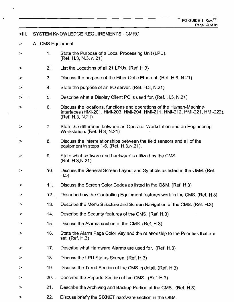
FO-GUIDE-1 Rev.11Page 59 of91
>111. SYSTEM KNOWLEDGE REQUIREMENTS - CMRO
> A. CMS Equipment
>
>
>
>
>
>
>
>
>
>
>
>
>
>
>
>
>
>
>
>
>
>
1. State the Purpose of a Local Processing Unit (LPU).(Ref. H.3, N.3, N.21)
2. List the Locations of all 21 LPUs. (Ref. H.3)
3. Discuss the purpose ofthe Fiber Optic Etherent. (Ref. H.3, N.21)
4. State the purpose of an 1/0 server. (Ref. H.3, N.21)
5. Describe what a Display Client PC is used for. (Ref. H.3, N.21)
6. Discuss the locations, functions and operations of the Human-MachineInterfaces (HMI-201, HMI-203, HMI-204, HMI-211, HMI-212, HMI-221, HMI-222).(Ref. H.3, N.21)
7. State the difference between an Operator Workstation and an EngineeringWorkstation. (Ref. H.3, N.21)
8. Discuss the interrelationships between the field sensors and all of theequipment in steps 1-6. (Ref. H.3,N.21).
9. State what software and hardware is utilized by the CMS.(Ref. H.3,N.21)
10. Discuss the General Screen Layout and Symbols as listed in the O&M. (Ref.H.3)
11. Discuss the Screen Color Codes as listed in the O&M. (Ref. H.3)
12. Describe how the Controlling Equipment features work in the CMS. (Ref. H.3)
13. Describe the Menu Structure and Screen Navigation of the CMS. (Ref. H.3)
14. Describe the Security features of the CMS. (Ref. H.3)
15. Discuss the Alarms section of the CMS. (Ref. H.3)
16. State the Alarm Page Color Key and the relationship to the Priorities that areset. (Ref. H.3)
17. Describe what Hardware Alarms are used for. (Ref. H.3)
18. Discuss the LPU Status Screen. (Ref. H.3)
19. Discuss the Trend Section of the CMS in detail. (Ref. H.3)
20. Describe the Reports Section of the CMS. (Ref. H.3)
21. Describe the Archiving and Backup Portion of the CMS. (Ref. H.3)
22. Discuss briefly the SIXNET hardware section in the O&M.
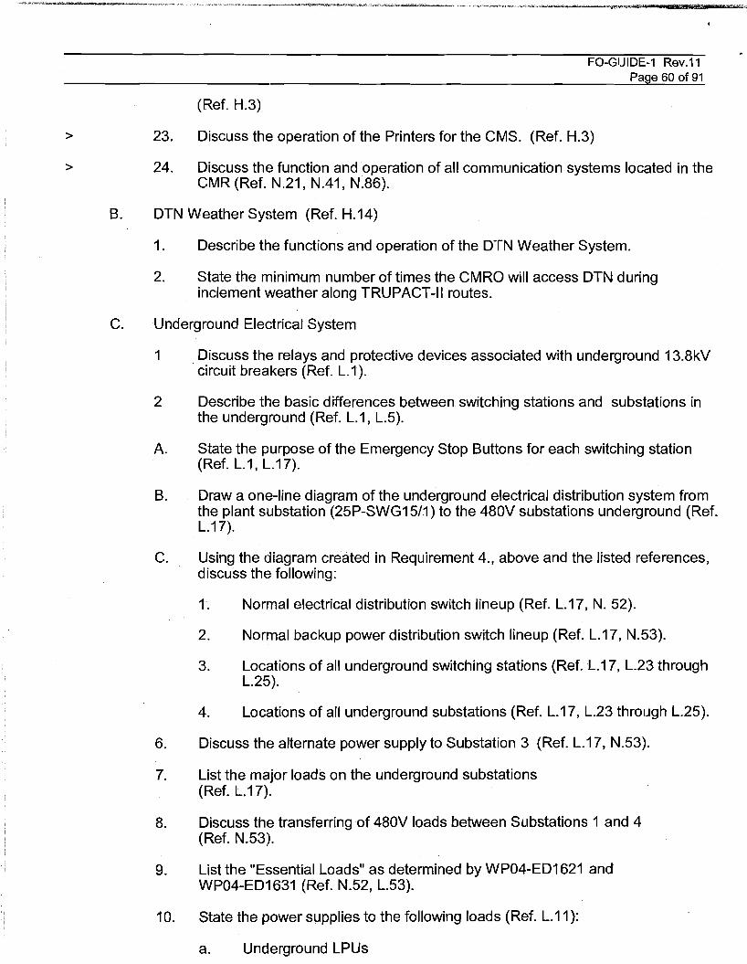
FO-GUIDE-1 Rev.11Page 60 of 91
(Ref. H.3)
>
>
23. Discuss the operation of the Printers for the CMS. (Ref. H.3)
24. Discuss the function and operation of all communication systems located in theCMR (Ref. N.21, N.41, N.86).
B. DTN Weather System (Ref. H.14)
1. Describe the functions and operation of the DTN Weather System.
2. State the minimum number of times the CMRO will access DTN duringinclement weather along TRUPACT-II routes.
C. Underground Electrical System
1 .Discuss the relays and protective devices associated with underground 13.8kVcircuit breakers (Ref. L.1).
2 Describe the basic differences between switching stations and substations inthe underground (Ref. L.1, L.5).
A. State the purpose of the Emergency Stop Buttons for each switching station(Ref. L.1, L.17).
B. Draw a one-line diagram of the underground electrical distribution system fromthe plant substation (25P-SWG1511) to the 480V substations underground (Ref.L.17).
C. Using the diagram created in Requirement 4., above and the listed references,discuss the following:
1. Normal electrical distribution switch lineup (Ref. L.17, N. 52).
2. Normal backup power distribution switch lineup (Ref. L.17, N.53).
3. Locations of all underground switching stations (Ref. L.17, L.23 throughL.25).
4. Locations of all underground substations (Ref. L.17, L.23 through L.25).
6. Discuss the alternate power supply to Substation 3 (Ref. L.17, N.53).
7. List the major loads on the underground substations(Ref. L.17).
8. Discuss the transferring of 480V loads between Substations 1 and 4(Ref. N.53).
9. List the "Essential Loads" as determined by WP04-ED1621 andWP04-ED1631 (Ref. N.52, L.53).
10. State the power supplies to the following loads (Ref. L.11):
a. Underground LPUs
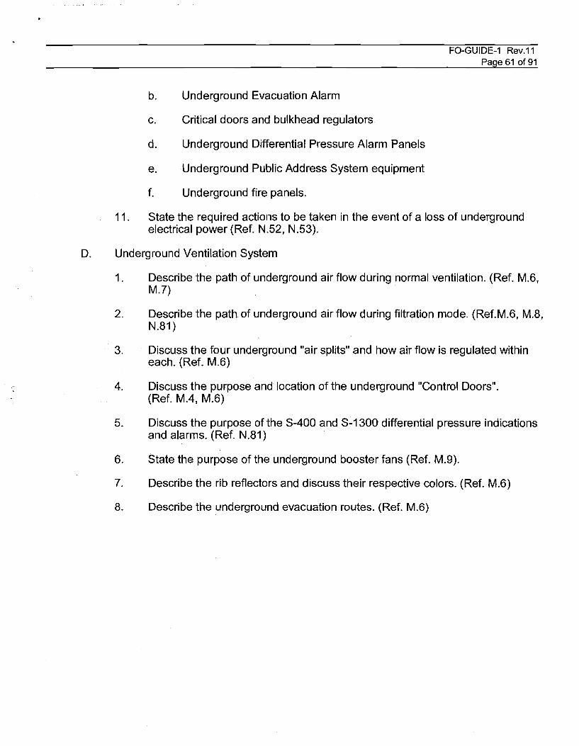
FO-GUIDE-1 Rev.11Page 61 of 91
b. Underground Evacuation Alarm
c. Critical doors and bulkhead regulators
d. Underground Differential Pressure Alarm Panels
e. Underground Public Address System equipment
f. Underground fire panels.
11. State the required actions to be taken in the event of a loss of undergroundelectrical power (Ref. N.52, N.53).
D. Underground Ventilation System
1. Describe the path of underground air flow during normal ventilation. (Ref. M.6,M.7)
2. Describe the path of underground air flow during filtration mode. (Ref.M.6, M.8,N.81)
3. Discuss the four underground "air splits" and how air flow is regulated withineach. (Ref. M.6)
4. Discuss the purpose and location of the underground "Control Doors".(Ref. MA, M.6)
5. Discuss the purpose of the S-400 and S-1300 differential pressure indicationsand alarms. (Ref. N.81)
6. State the purpose of the underground booster fans (Ref. M.9).
7. Describe the rib reflectors and discuss their respective colors. (Ref. M.6)
8. Describe the underground evacuation routes. (Ref. M.6)
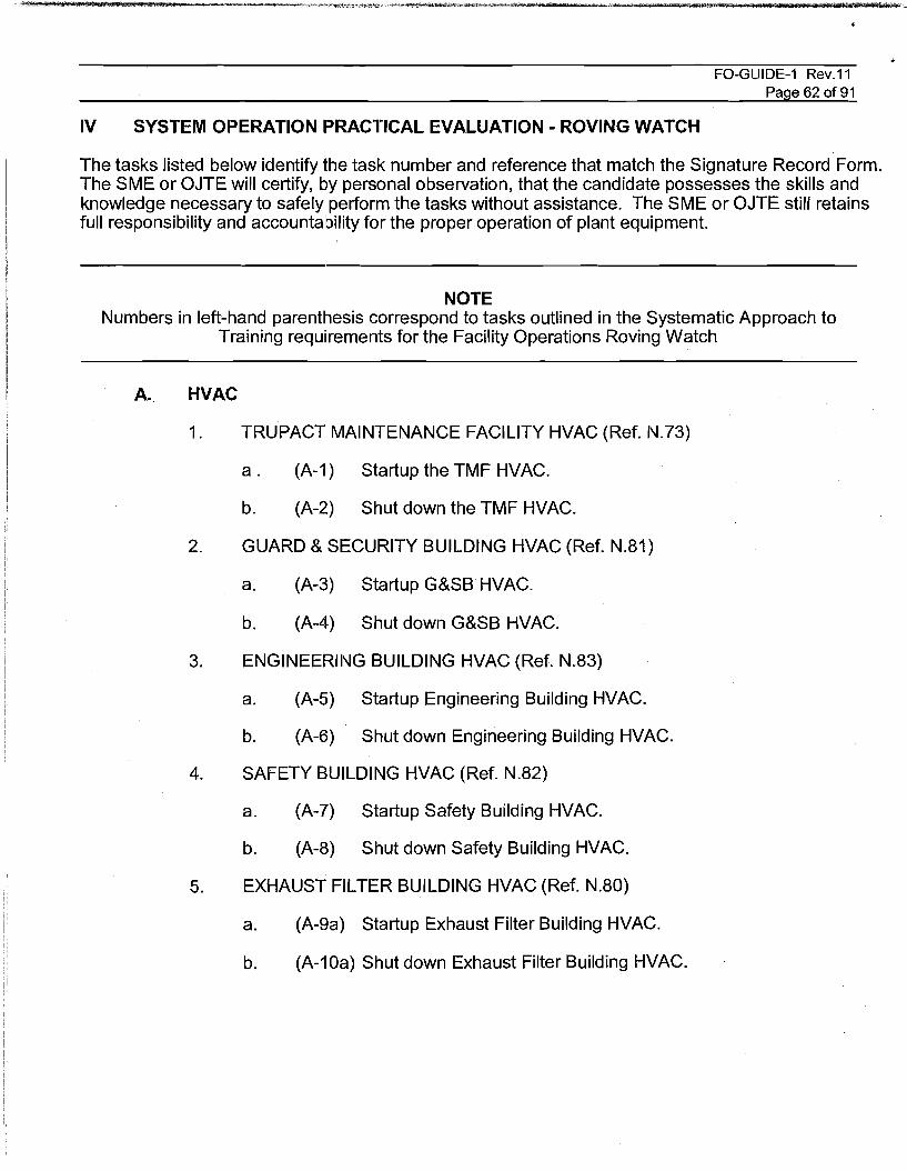
FO-GUIDE-1 Rev.11Page 62 of91
IV SYSTEM OPERATION PRACTICAL EVALUATION - ROVING WATCH
The tasks listed below identify the task number and reference that match the Signature Record Form.The SME or OJTE will certify, by personal observation, that the candidate possesses the skills andknowledge necessary to safely perform the tasks without assistance. The SME or OJTE still retainsfull responsibility and accountability for the proper operation of plant equipment.
NOTEl\Jumbers in left-hand parenthesis correspond to tasks outlined in the Systematic Approach to
Training requ~rements for the Facility Operations Roving Watch
A. HVAC
1. TRUPACT MAINTENANCE FACILITY HVAC (Ref. 1\J.73)
a . (A-1) Startup the TMF HVAC.
b. (A-2) Shut down the TMF HVAC.
2. GUARD & SECURITY BUILDING HVAC (Ref. N.81)
a. (A·3) Startup G&SB HVAC.
b. (A-4) Shut down G&SB HVAC.
3. ENGINEERII\JG BUILDING HVAC (Ref. N.83)
a. (A-5) Startup Engineering Building HVAC.
b. (A-6) Shut down Engineering Building HVAC.
4. SAFETY BUILDING HVAC (Ref. N.82)
a. (A-7) Startup Safety Building HVAC.
b. (A-8) Shut down Safety Building HVAC.
5. EXHAUST FILTER BUILDING HVAC (Ref. N.80)
a. (A-9a) Startup Exhaust Filter Building HVAC.
b. (A-10a) Shut down Exhaust Filter Building HVAC.
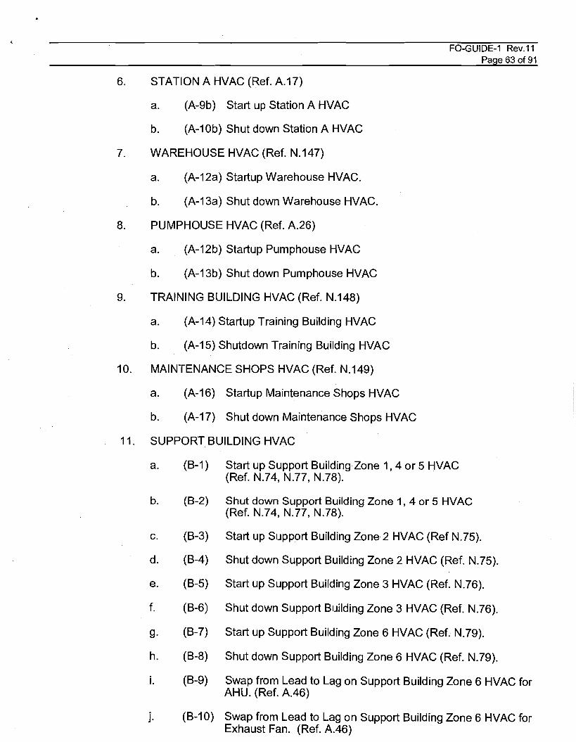
6. STATION A HVAC (Ref. A.17)
a. (A-9b) Start up Station A HVAC
b. (A-10b) Shut down Station A HVAC
7. WAREHOUSE HVAC (Ref. N.147)
a. (A-12a) Startup Warehouse HVAC.
b. (A-13a) Shut down Warehouse HVAC.
8. PUMPHOUSE HVAC (Ref. A.26)
a. (A-12b) Startup Pumphouse HVAC
b. (A-13b) Shut down Pumphouse HVAC
9. TRAINING BUILDING HVAC (Ref. N.148)
a. (A-14) Startup Training Building HVAC
b. (A-15) Shutdown Training Building HVAC
10. MAINTENANCE SHOPS HVAC (Ref. N.149)
a. (A-16) Startup Maintenance Shops HVAC
b. . (A-17) Shut down Maintenance Shops HVAC
11. SUPPORT BUILDING HVAC
FO-GUIDE-1 Rev.11Page 63 of 91
a. (B-1 ) Start up Support Building Zone 1,4 or 5 HVAC(Ref. N.74, N.77, N.78).
b. (B-2) Shut down Support Building Zone 1, 4 or 5 HVAC(Ref. N.74, N.77, N.78).
c. (B-3) Start up Support Building Zone 2 HVAC (Ref N.75).
d. (B-4) Shut down Support Building Zone 2 HVAC (Ref. N.75).
e. (B-5) Start up Support Building Zone 3 HVAC (Ref. N.76).
f. (B-6) Shut down Support Building Zone 3 HVAC (Ref. N.76).
g. (B-7) Start up Support Building Zone 6 HVAC (Ref. N.79).
h. (B-8) Shut down Support Building Zone 6 HVAC (Ref. N.79).
i. (B-9) Swap from Lead to Lag on Support Building Zone 6 HVAC forAHU. (Ref. A.46)
j. (B-10) Swap from Lead to Lag on Support Building Zone 6 HVAC forExhaust Fan. (Ref. A.46)
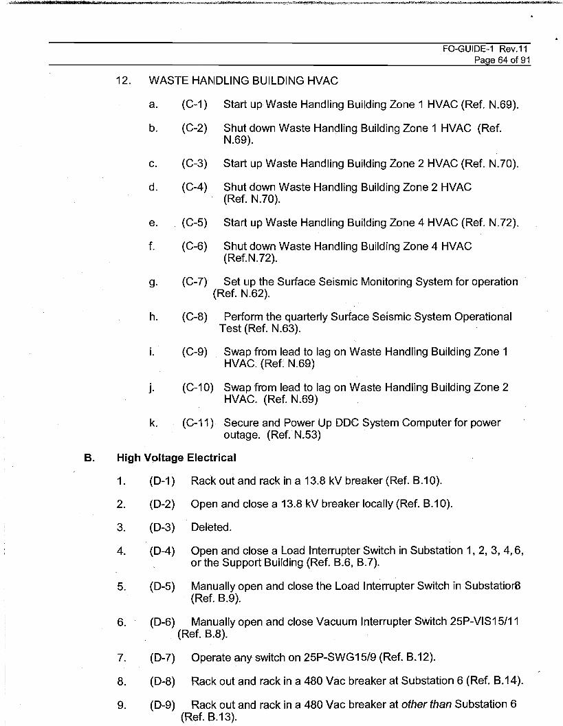
FO-GUIDE-1 Rev.11Page 64 of 91
12. WASTE HAI\IDLING BUILDING HVAC
a.
b.
(C-1 )
(C-2)
Start up Waste Handling Building Zone 1 HVAC (Ref. N.69).
Shut down Waste Handling Building Zone 1 HVAC (Ref.1\1.69).
c.
d.
(C-3)
(C-4)
Start up Waste Handling Building Zone 2 HVAC (Ref. N.70).
Shut down Waste Handling Building Zone 2 HVAC(Ref. N.70).
e.
f.
(C-5)
(C-6)
Start up Waste Handling Building Zone 4 HVAC (Ref. N.72).
Shut down Waste Handling Building Zone 4 HVAC(Ref.N.72).
g. (C-7) Set Lip the Surface Seismic Monitoring System for operation(Ref. N.62).
h. (C-8) Perform the quarterly Surface Seismic System OperationalTest (Ref. N.63).
i. (C-9) Swap from lead to lag on Waste Handling Building Zone 1HVAC. (Ref. N.69)
j. (C-10) Swap from lead to lag on Waste Handling Building Zone 2HVAC. (Ref. N.69)
k. (C-11) Secure and Power Up DDC System Computer for poweroutage. (Ref. N.53)
Manually open and close the Load Interrupter Switch in SubstatiorB(Ref. B.9).
Open and close a Load Interrupter Switch in Substation 1,2,3, 4,6,or the Support Building (Ref. B.6, B.7).
1. (D-1 )
2. (D-2)
3. (D-3)
4. (D-4)
5. (D-5)
B. High Vpltage Electrical
Rack out and rack in a 13.8 kV breaker (Ref. B.10).
Open and close a 13.8 kV breaker locally (Ref. B.10).
Deleted.
6. (D-6) Manually open and close Vacuum Interrupter SWitch 25P-VIS15/11(Ref. B.8).
7. (D-7) Operate any switch on 25P-SWG15/9 (Ref. B.12).
8. (D-8) Rack out and rack in a 480 Vac breaker at Substation 6 (Ref. B.14).
9. (D-9) Rack out and rack in a 480 Vac breaker at other than Substation 6(Ref. B.13).
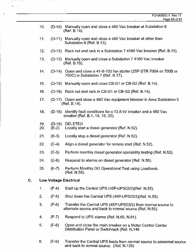
FO-GUIDE-1 Rev.11Page 65 of91
10. (0-10) Manually open and close a 480 Vac breaker at Substation 6(Ref. B.14).
11. (0-11) Manually open and close a 480 Vac breaker at other thanSubstation 6 (Ref. B.13).
12. (0-12) Rack out and rack in a Substation 7 4160 Vac breaker (Ref. 8.15).
13. (0-13) Manually open and close a Substation 7 4160 Vac breaker(Ref. B.15).
14. (0-14) Open and close a 41-B-700 fan starter (25P-STR-700A or 700B or700C) in Substation 7(Ref. B.17).
15. (0-15) Manually open and close CB-G1 or CB-G2 (Ref. 8.14).
16. (0-16) Rack out and rack in CB-G1 or CB-G2 (Ref. B.14).
17. (0-17) Open and close a 480 Vac equipment breaker in Area Substation 5(Ref. B.14).
18. (0-18) Identify fault conditions for a 13.8 kV breaker and a 480 Vacbreaker (Ref. 8.1, 18, 19, 20).
19.20.
21.
22.
23.
24.
25.
(0-19)(E-2)
(E-3)
(E-4)
(E-5)
(E-6)
(E-7)
DELETEDLocally start a diesel generator (Ref. N.52).
Locally stop a diesel generator (Ref. N.52).
Align a diesel generator for remote start (Ref. N.52).
Perform monthly diesel generator operability testing (Ref. N.52).
Respond to alarms on diesel generator (Ref. N.58).
Perform Monthly OG Operational Test using Loadbank.(Ref. N.58).
C. Low Voltage Electrical
1.
2.
3.
4.
5.
6.
(F-4)
(F-5)
(F-6)
(F-7)
(F-8)
(F-9)
Start up the Central UPS (45P-UPS03/2)(Ref. N.55).>
Shut down the Central UPS (45P-UPS03/2)(Ref. N.55).
Transfer the Central UPS (45P-UPS03/2) from normal source toalternate source and back to normal source (Ref. N.55).
Respond to UPS alarms (Ref. N.60, N.61).
Open and close the main breaker on a Motor Control CenterDistribution Panel or Switchrack (Ref. N.146
. Transfer the Central UPS loads from normal source to abnormal sourceand back to normal source. (Ref. N.139)
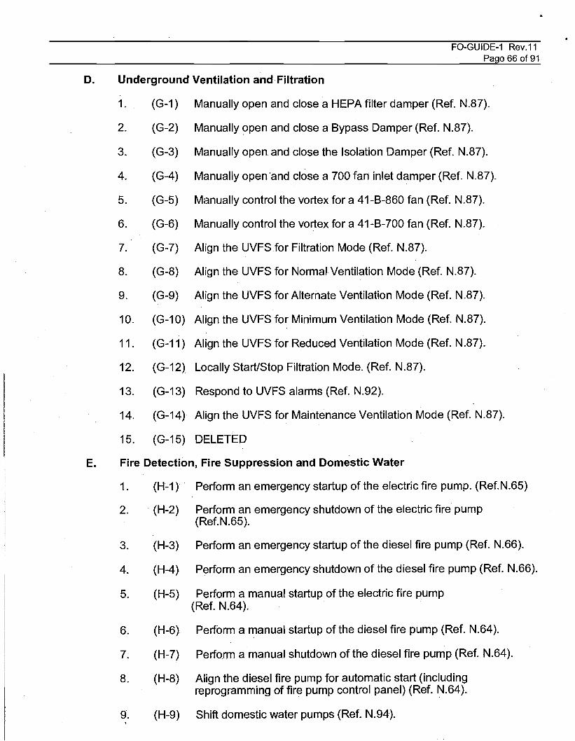
D. Underground Ventilation and Filtration
FO-GUIDE-1 Rev.11Page 66 of 91
1. (G-1) Manually open and close a HEPA filter damper (Ref. N.87).
2. (G-2) Manually open and close a Bypass Damper (Ref. N.87).
3. (G-3) Manually open and close the Isolation Damper (Ref. N.87).
4. (G-4) Manually open 'and close a 700 fan inlet damper (Ref. N.87).
5. (G-5) Manually control the vortex for a 41-B-860 fan (Ref. N.87).
6. (G-6) Manually control the vortex for a 41-B-700 fan (Ref. N.87).
7. (G-7) Align the UVFS for Filtration Mode (Ref. N.87).
8. (G-8) Align the UVFS for Normal Ventilation Mode (Ref. N.87).
9. (G-9) Align the UVFS for Alternate Ventilation Mode (Ref. N.87).
10. (G-10) Align the UVFS for Minimum Ventilation Mode (Ref. N.87).
11. (G-11 ) Align the UVFS for Reduced Ventilation Mode (Ref. N.87).
12. (G-12) Locally Start/Stop Filtration Mode. (Ref. N.87).
13. (G-13) Respond to UVFS alarms (Ref. N.92).
14. (G-14) Align the UVFS for Maintenance Ventilation Mode (Ref. N.87).
15. (G-15) DELETED
E. Fire Detection, Fire Suppression and Domestic Water
1. (H-1) Perform an emergency startup of the electric fire pump. (Ref.N.65)
2. . (H-2) Perform an emergency shutdown of the electric fire pump(Ref.N.65).
3. (H-3) Perform an emergency startup of the diesel fire pump (Ref. N.66).
4. (H-4) Perform an emergency shutdown of the diesel fire pump (Ref. N.66).
5. (H-5) Perform a manual startup of the electric fire pump(Ref. N.64).
6. (H-6) Perform a manual startup of the diesel fire pump (Ref. N.64).
7. (H-7) Perform a manual shutdown of the diesel fire pump (Ref. N.64).
8. (H-8) Align the diesel fire pump for automatic start (includingreprogramming of fire pump control panel) (Ref. N.64).
9. (H-9) Shift domestic water pumps (Ref. N.94).
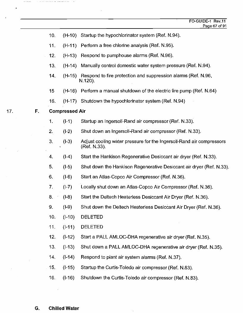
17. F.
FO-GUIDE-1 Rev.11Page 67 of 91
10. (H-10) Startup the hypochlorinator system (Ref. N.94).
11. (H-11) Perform a free chlorine analysis (Ref. N.95).
12. (H-13) Respond to pumphouse alarms (Ref. N.96).
13. (H-14) Manually control domestic water system pressure (Ref. N.94).
14. (H-15) Respond to fire protection and suppression alarms (Ref. N.96,N.120).
15 (H-16) Perform a manual shutdown of the electric fire pump (Ref. N.64)
16. (H-17) Shutdown the hypochlorinator system (Ref. N.94)
Compressed Air
1. (1-1 ) Startup an Ingersoll-Rand air compressor (Ref. N.33).
2. (1-2) Shut down an Ingersoll-Rand air compressor (Ref. N.33).
3. (1-3) Adjust cooling water pressure for the Ingersoll-Rand air compressors(Ref. N.33).
4. (1-4) Start the Hankison Regenerative Desiccant air dryer (Ref. N.33).
5. (1-5) Shut down the Hankison Regenerative Desiccant air dryer (Ref. N.33).
6. (1-6) Start an Atlas-Copco Air Compressor (Ref. N.36).
7. (1-7) Locally shut down an Atlas-Copco Air Compressor (Ref. N.36).
8. (1-8) Start the Deltech Heaterless Desiccant Air Dryer (Ref. N.36).
9. (1-9) Shut down the Deltech Heaterless Desiccant Air Dryer (Ref. N.36).
10. (1-10) DELETED
11. (1-11 ) DELETED
12. (1-12) Start a PALL AMLOC-DHA regenerative air dryer (Ref. N.35).
13. (1-13) Shutdown a PALL AMLOC-DHA regenerative air dryer (Ref. N.35).
14. (1-14) Respond to plant air system alarms (Ref. N.37).
15. (1-15) Startup the Curtis-Toledo air compressor (Ref. N.83).
16. (1-16) Shutdown the Curtis-Toledo air compressor (Ref. N.83).
G. Chilled Water

"'%&ei!:' 11 ..• m-nc 1 N 1 @17%"'- '. M 1& r TR
FO-GUIDE-1 Rev.11Page 68 of91
1. (J-1 )
2. (J-2)
3. (J-3)
4. (J-4)
5. (J-5)
6. (J-6)
7. (J-7)
8. (J-8)
Adjust pressure of the Chilled Water system (Ref. NA8).
Startup a main chiller (Ref. NA8).
Shut down a main chiller (Ref. NA8).
Startup Engineering Building Chiller (Ref. N.83).
Shut down Engineering Building Chiller (Ref. N.83).
Startup the Safety Building Chiller (Ref. N.82).
Shut down the Safety Building Chiller (Ref. N.82).
Delete
H. Central Monitoring System
1. (K-1) Startup a Local Processing Unit and a Fiber Optic Repeater(Ref.N.45, N.54).
2. (K-2) Shut down a Toshiba UPS (Ref. N.45).
3. (K-3) Startup a Toshiba UPS (Ref. N.45).
4. (K-4) Shut down the Best 5kVA UPS (Ref. N.45).
5. (K-5) Startup the Best 5kVA UPS (Ref. N.45).
6. (K-6) Respond to LPU/UPS alarms (Ref. N.45).
7. (K-7) Startup a Operator's or Engineer's Station(Ref. N.43).
8. (K-8) Shutdown a Local Processing Unit and a Fiber Optic Repeater(Ref. N.45, N.54).
9. (K-9) Shutdown a Operator's or Engineer's Station (Ref. N.43)
1. (L-1 )
2. (L-2)
3. (L-~)
J. Surface Fuel Station
1. (M-1) Perform a weekly alarm and circuit check of the Surface FuelSystem (Ref. N.68).
2. (M-3) Calculate fuel transfer (Ref. N.68).
3. (M-4) Respond to monitoring system alarms (Ref. N.68).

K. Plant Vacuum
1. (N-1 )
2. (N-2)
3. (N-3)
Start up a Vacuum pump (Ref. N.B?).
Shut down a Vacuum pump (Ref. N.B?).
Respond to vacuum system alarms (Ref. N.B?).
FO-GUIDE-1 Rev.11Page 69 of91

FO-GUIDE-1 Rev.11Page 70 of 91
IV. SYSTEM OPERATION PRACTICAL EVALUATION - CMRO
The tasks listed below identify the task number and reference that match the Signature RecordForm. The SME or OJTE will certify, by personal observation, that the candidate possessesthe skills and knowledge necessary to safely perform the tasks without assistance. The SMEor OJTE still retain full responsibility and accountability. for the proper operation of plantequipment.
NOTENumbers in left-hand parenthesis correspond to tasks outlined in the Systematic Approach to
Training requirements for the Central Monitoring Room Operator
SYSTEM OPERATION PRACTICAL EVALUATION - CMRO
A. CMS Equipment Operation
> 1. (A-1 ) Logoff and Shutdown an Operator Station from a running state.(Ref. H.3, N.21)
> 2. (A-2) Startup and Logon to an Operator Station from a cold state.(Ref. H.3, N.21)
> 3. (A-3) Navigate through all available graphics in the CMS. (Ref. H.3)
> 4. (A-4) Print a Graphic from any HMI. (Ref. H.3)
> 5. (A-5) Acknowledge any received alarms. (Ref. H.3)
> 6. (A-6) Setup a Trend as directed by the Evaluator. (Ref. H.3)
> 7. (A-7) Perform a System Backup as directed by the Evaluator. (Ref.H.3)
> 8. (B-1 ) Make an announcement using the site Public Address System(Ref. N.41).
> 9. (B-2) Make an announcement using the Site Notification System (Ref.N.41 ).
> 10. (B-3) Initiate a page and communicate using the Mine Pager Phone(Ref. N.41).
> 11. (B-4) Communicate using the Zone Talk feature of the site PublicAddress System (Ref. N.41).
> 12. (B-5) Initiate a Surfac;e Evacuation (Ref. N.41).
> 13. (B-6) Reset a Surface Evacuation Alarm (Ref. N.41).
> 14. (B-7) Manually initiate an Underground Evac Alarm (Ref. N.41).
> 15. (B-8) Reset an Underground Evacuation Alarm (Ref. N.41).
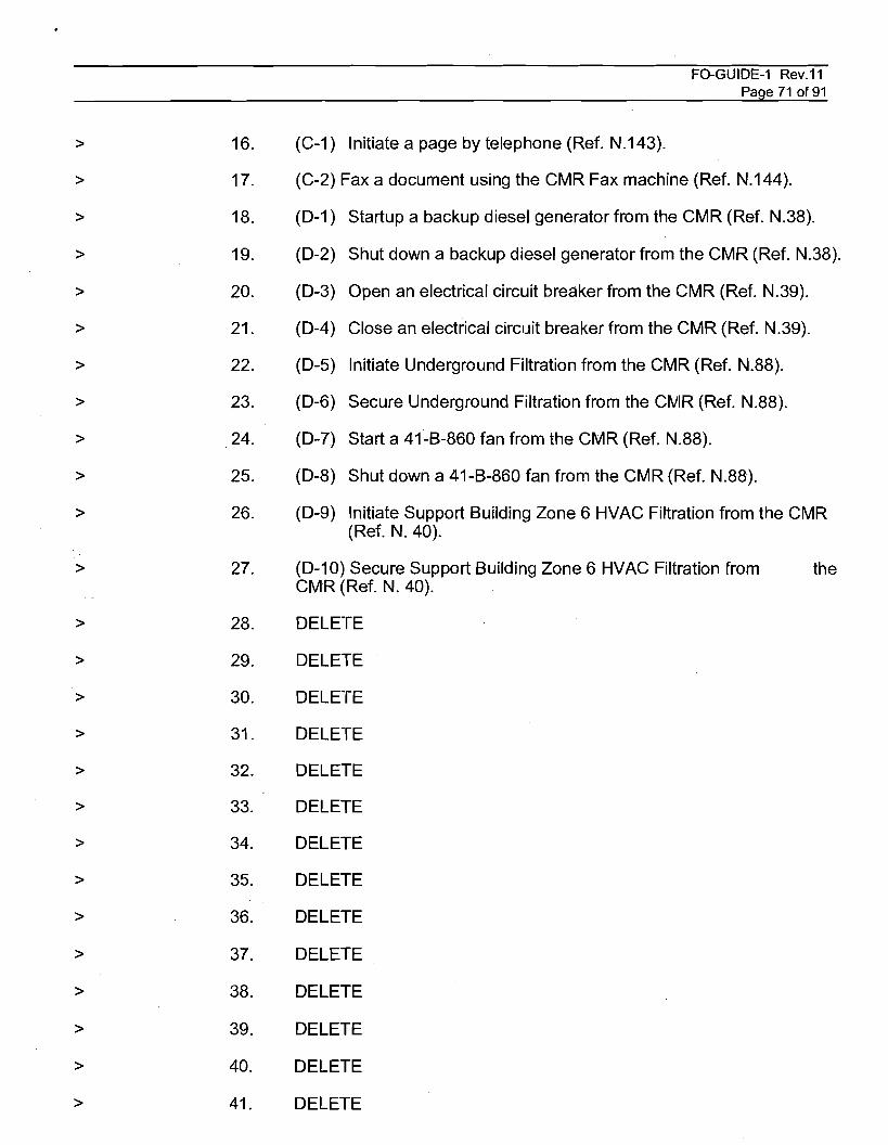
FO-GUIDE-1 Rev.11Page 71 of91
> 16. (C-1 ) Initiate a page by telephone (Ref. N.143).
> 17. (C-2) Fax a document using the CMR Fax machine (Ref. N.144).
> 18. (D-1 ) Startup a backup diesel generator from the CMR (Ref. N.38).
> 19. (D-2) Shut down a backup diesel generator from the CMR (Ref. N.38).
> 20. (D-3) Open an electrical circuit breaker from the CMR (Ref. N.39).
> 21. (D-4) Close an electrical circuit breaker from the CMR (Ref. N.39).
> 22. (D-5) Initiate Underground Filtration from the CMR (Ref. N.88).
> 23. (D-6) Secure Underground Filtration from the CNiR (Ref. N.88).
> 24. (D-7) Start a 41-B-860 fan from the CMR (Ref. N.88).
> 25. (D-8) Shut down a 41-B-860 fan from the CMR (Ref. N.88).
> 26. (D-9) Initiate Support Building Zone 6 HVAC Filtration from the CMR(Ref. N. 40).
> 27. (D-10) Secure Support Building Zone 6 HVAC Filtration from theCMR (Ref. N. 40).
> 28. DELETE
> 29. DELETE
> 30. DELETE
> 31. DELETE
> 32. DELETE
> 33. DELETE
> 34. DELETE
> 35. DELETE
> 36. DELETE
> 37. DELETE
> 38. DELETE
> 39. DELETE
> 40. DELETE
> 41. DELETE
>
>
42.
43.
DELETE
DELETE
FO-GUIDE-1 Rev.11Page 72 of 91
FO-GUIDE-1 Rev.11Page 73 of 91
V. ADMINISTRATIVE REQUIREMENTS - ROVING WATCH
A. Equipment TagoutlLockout (Ref. N.30)
1. State the purpose of a Danger Tag.
2. State the purpose of a Caution Tag.
3. State the conditions that require an operations lock to accompany a tagout.
4. State the personnel who are authorized to place Operations locks and tags.
5. State when Operations locks and tags are placed and removed with respect toMaintenance locks.
6. Describe the precautions observed when placing a tag on a component.
7. State the conditions that must be met if a maintenance lock must be removedand the technician who installed the lock is not available. (Ref. N.103)
8. State the concurrence requirements for tagouts involving fire protectionequipment.
9. Describe the requirements for tagging mobile equipment.
10. State the consequences of intentionally violating a lockout/tagout.
11. State the frequency of tagout/lockout audit performance,
12. Describe the method used to add work packages to a Tagout/Lockout ControlSheet.
13. State what sources may be utilized to determine the proper location forplacement of danger tags.
14. Describe the requirements for stored energy devices. (Ref. N.30, N.103, N.109)
15. State the conditions required to allow removal of a tagout/lockout.
16. Describe the actions that must be taken if a discrepancy is found during atagout/lockout audit.
B. Temporary Plant Modification (Ref. N.31)
1. State the purpose of the Temporary Plant Modification Control Procedure.
2. State the definition of a Temporary Plant Modification. (TPM)
3. Describe the responsibilities of the Cognizant Operations Supervisor in regardto the TPM control procedure.
4. Discuss the precautions and limitations associated with the TPM controlprocedure.
5. Discuss the policies which govern the use ofTPMs.
".;.."""<'jt\....'_......_tMfl.....Kii!i .._Biil:_~_'_.:!'!L_g_.f_:._F.. _. .'1-_' ._-","_.. _ .__,_._:~_-~-_f.-.....,TT_._J*_-r__4: ..·_--yc_r"t....·, -_\if""-1_.ft;'....__,_.,~_'...,-1/_.01........._.-"_'1iI_~ii1I....__ '!if strwi
FO-GUIDE-1 Rev.11Page 74 of 91
6. State the type of work which is excluded from TPM control.
7. State the physical requirements that must be met by mechanical and electricaljumpers.
8. State the physical requirements that must be met by lifted leads and blankflanges.
9. State the notification requirements when authorizing a TPM for OSR equipment.
10. Discuss the requirements for completing blocks 1 through 19 of the TPM ControlRecord form.
11. State the source of retest requirements upon restoration of equipment from aTPM.
12. State the frequency of a TPM Control Record Sheet audit.
13. State the actions required if a discrepancy is found during a TPM ControlRecord Sheet audit.
14. Discuss the TPM Control record keeping requirements.
C. Work Authorization (Ref. N.104 and 1\J.105)
1. State the purpose of an Action Request (AR).
2. Discuss the "graded approach" to site maintenance as it relates to plant workperformance.
3. State the purpose of a Work Change Notice (WCN).
4. Describe work that is excluded from the authority of the Work Authorizationprocedure"
5. State who the initiator of an AR shall be.
6. State where the retest requirements can be found or who stipulates the retestrequirements if the AR or Preventive Maintenance (PM) instruction does notaddress a retest.
o Conduct of Opelrations (Ref. N.47)
1. Discuss the responsibilities of the Facility Operations Roving Watch.
2. Discuss the responsibilities of theCMRO.
3. Discuss the watchstanding practices as described in the Conduct of OperationsManual.
4. State the requirements for a procedure to be open and in step-by-step use.
5. State the requirements that must be met to use a performance copy of aprocedure that contains signoffs.
FO-GUIDE-1 Rev.11Page 75 of 91
6. Describe the conditions which must be met in order for the operator not to havea procedure open and in step-by-step use during an evolution.
7. State the actions that an operator shall be capable of performing withoutreference to a procedure in an abnormal or emergency event.
8. State the action required by an operator if a procedure cannot be performed aswritten.
9. State the actions required if a procedure or evolution has been stopped due to aproblem or shift turnover.
10. Discuss the requirements of good communications techniques as described inthe Conduct of Operations Manual.
11. Discuss the requirements of good logkeeping techniques as described in theConduct of Shift Operations Manual and the Shift Operating Logs Procedure(Ref. N.29)
12. Discuss the fundamental principle of "Believe Your Indication" as it pertains tofacility instrumentation.
13. Discuss the good practices of monitoring instrumentation as described in theConduct of Operations Manual.
14. Discuss the good practices of performing watchstation tours and monitoringsystems and equipment as described in the Conduct of Operations Manual.
15. Discuss the responsibilities of all operators in the event of any facility problem.
16. Discuss the requirements for logging a facility problem.
17. Discuss the good safety practices as described in the Conduct of OperationsManual.
18. Discuss the requirements governing the performance of On-the-Job Training asdescribed in the Conduct of Operations Manual.
19. Discuss the requirements for performing a watchstation or Shift Turnover asdescribed in the Conduct of Operations Manual.
20. Discuss the purpose and requirements for reviewing required reading asdescribed in the Conduct of Operations Manual.
E. Control of Operator Aids (Ref. N.85)
1. State the purpose of the Control of Operation Aids procedure.
2. State the person responsible for approving the posting of an operator aid.
F. Facility Emergencies
1. State the purpose of the WIPP Emergency Plan. (Ref. N.110)

mew t ct
FO-GUIDE-1 Rev.11Page 76 of91
2. Discuss the types of emergencies covered in the WIPP Emergency Plan. (Ref.N.110)
3. Discuss the emergency notification requirements of the WIPP Emergency Planand other directives. (Ref. N.11 0, N.124)
4. State the time requirement for classification of reportable occurrences for WP12-ES3918. (Ref. N.124)
G. System Lineups (Ref. N.27)
1. Describe the methods for determining if a system lineup is required.
2. Discuss the general techniques employed in performing system lineups.
3. State the responsibilities of the Positioner.
4. State the responsibilities of the Independent Verifier.
5. Discuss the specific requirements and methods for checking the position ofvalves, valve operator clutches, dampers, circuit breakers, and switches.
H. Technical Safety Requirements (Ref. N.26, N.32, N.89, N.134, 1\1.135)
1. List the equipment operating requirements from Administrative Control of theWIPP TSR for both operating modes.
2. List the differences in facility staffing requirements between WasteStorage/Disposal Mode and Waste Handling Mode.
3. Describe the responsibility of each watchstander in ensuring compliance withthe Facility Staffing and Facility Staff Qualifications Administrative Controls ofthe WIPP TSR. .
4. Discuss the Administrative controls of the WIPP TSR.
5. Describe the "Defense-In-Depth" philosophy regarding accident mitigation asdiscussed in the WIPP SAR and TSR.
6. Discuss the difference between "Operability Tests" and "SurveillanceRequirements" as viewed from a SAR perspective (Limiting Conditions forOperation versus Administrative Controls)
7. Discuss the Operability Tests performed by Facility Operations to validateequipment operability for Administrative Control 5.1 of the TSR.
8. List the actions required of any individual who suspects that a TSRAdministrative Control has been violated.

FO-GUIDE-1 Rev.11Page 77 of 91
I. Guidelines for Operating Electrical Components (Ref. N.107)
A. Define the electrical plane and when it may be crossed.
B. Discuss minimum Personal Protective Equipment (PPE) and precautions usedwhile operating Circuit Breakers.
C. Discuss minimum PPE and precautions used for racking in/out CircuitBreakers.

FO-GUIDE-1 Rev.11Page 78 of 91
V. ADMINISTRATIVE REQUIREMENTS - CMRO
A. CMS Alarm Enable/Disable Authorization
>
>
>
>
>
1.
2.
3.
4.
5.
State the person responsible for authorizing the enabling and disabling of CMSalarms.
Discuss the contents of the CMS Alarm Enable/Disable Logbook.
Discuss the documentation of a CMS Alarm Enable/Disable.
Discuss the process on how to Enable or Disable a CMS Alarm.
Discuss the weekly logbook review procedure
B. Facility Emergencies
> 1. State the responsibility of the CMRO in the notification process following anoccurrence (Ref. N.110, N.124).
2.> Discuss appropriate use of the public address system for personal,informational and emergency announcements (Ref. N.41, N.47).
C. Waste Handling Operations
>
>
>
>
>
1.
2.
3.
4.
5.
Discuss the surface waste handling process. (Ref. N.137)
Discuss the underground waste handling process. (Ref. N.137)
Discuss Waste Handling actions during an abnormal event. (Ref. N.138)
Discuss Waste Handling actions taken for a suspended 10ad.(Ref. N.138)
Discuss expected communication during daily operation. (Ref. N.137)
D. Mode Compliance
>
>
1.
2.
Discuss how to complete each line item on the Waste/Storage Mode FacilityChecklist. (Ref. N.26)
Discuss how to complete each line item on the Waste Handling Mode FacilityChecklist. (Ref. N.26)

•
FO-GUIDE-1 Rev.11Page 79 of 91
VI ADMINISTRATIVE REQUIREMENTS PRACTICAL EVALUATION - ROVING WATCH
NOTENumbers in left-hand parenthesis correspond to tasks outlined in the Systematic Approach to
Training requirements for the Facility Operations Roving Watch
A. Equipment Tagout/Lockout. (Ref. N.30)
1. (0-1) Prepare an equipment Tagout/Lockout Control Sheet and theassociated tags for a facility component as specified by the evaluator.
2. (0-2) After the equipment tagout/lockout has been authorized, place theequipment tagout/lockout on the specified component.
3. (0-3) Remove the equipment tagout/lockout that was placed in practicalRequirement 0-2.
4. (0-4) Perform a tagout/lockout audit.
B. Temporary Plant Modification. (Ref N.31)
1. (0-5) Given specific information for placing a TPM on a plant component,prepare a TPM Control Record Form.
2. (0-6) Perform a TPM Control Record Form audit.
.. C. Work Authorization (Ref. N.30, N.1 04)
1. (0-8) Review awork package for completeness and equipmenttagout/lockout requirements.
D. System Lineups (Ref. N.27)
1. (0-14) Perform a system lineup as the positioner.

~". txm 4"
FO-GUIDE-1 Rev.11Page 80 of91
VI. ADMINISTRATIVE REQUIREMENTS PRACTICAL EVALUATION - CMRO
> A. CMS Alarm Enable/Disable
> 1. (E-1) Perform a weekly Enable/Disable logbook review.
>
>
>
>
>
>
>
>
>
>
B. Facility Emergencies
Demonstrate (or Simulate) the CMRO responses required for each of the followingplant casualties and facility emergencies:
1. (E-2) Surface Fire (Ref. N.120).
2. (E-3) Underground Fire (Ref. N.122).
3. (E-4) Hazardous Material Spill (Ref. N.115).
4. (E-5) Severe WeatherlTornado (Ref. N.114).
5. (E-6) Earthquake/Seismic Event (Ref. N.121).
6. (E-7) Site Evacuation (Ref. N.119).
7. (E-8) Medical Emergency (Ref. N.118, N.123).
8. (E-9) Security Emergency (Ref. N.117).
9. (E-10) Respond to system alarms:
>
>
>
>
a.
b.
c.
d.
UVFS Fan High Vibration Alarm (Ref. N.93).
UVFS Ventilation Fan High Low Flow Alarm (Ref. N.93).
UVFS HEPA Filter High Differential Pressure Alarm (Ref. N.93).
Waste Hoist Tower High Differential Pressure Alarm (Ref. N.93).
> 10. (E-11) Respond to Hazardous Material Transportation Event (Ref. N.97).
> 11. (E-12) Respond to a Radcon Event (Ref. N.116)
>
>
12. (E-13) Respond to a Loss of CH HVAC (Ref. N.83)
13. (E-14) Respond to Loss of Underground Ventilation (Ref. N.92)
C. Waste Handling Operations
/
>
>
>
1.
2.
3.
(E-15) Respond to Waste Handling Immediate Danger Abnormal Event (Ref.N.138)
(E-16) Respond to Waste Handling "Other" Abnormal Event(Ref. N.138)
(E-17) Perform a walkthrough or observe the surface waste handling process.

•
FO-GUIDE-1 Rev.11Page 81 of 91
(Ref. N.137)
> 4. (E-18) Perform a walkthrough or observe the underground waste handlingprocess. (Ref. N.137)
D. Mode Compliance
>
>
1.
2.
(E-19) Complete a Waste/Storage Disposal Mode Checklist. (Ref. N.26)
(E-20) Complete a Waste Handling Mode Checklist. (Ref. N.26)

FO-GUIDE-1 Rev.11Page 82 of91
V. ADMINISTRATIVE REQUIREMENTS - FACILITY OPERATIONS SHIFT ENGINEER
A. Equipment Tagout/Lockout (Ref. N.30)
1. Discuss the retention and storage requirements for active and supersededTagout/Lockout Control Sheets.
2. Discuss the importance of understanding plant configuration as it applies to thefollowing:
a. Mode Compliance equipment
b; RCRA equipment (Appendices F & G)
c. Facility Availability Equipment
d. Open or active work orders in progress under the same or relatedtagout.
B. Temporary Plant Modification Control (Ref. N.31)
1.· Discuss the importance of understanding plant configuration as it applies to thefollowing:
a. Mode Compliance Equipment
b. RCRA equipment (Appendices F & G)
c. Facility Availability Equipment
2. State when special training related to TPMs must be conducted and what formsthis training may take.
C. Conduct of Operations (Ref. N.47)
1. Discuss the purpose and requirements for reviewing shift instructions asdescribed iin Section 17 of the Conduct of Operations Manual.
2. Discuss the responsibilities of the FSM and the Facility Engineer.
3. State the reporting chain within the Facility Operations and from the FSM to theWTS General Manager
4. State the purpose of the Conduct of Operations Manual.
5. Discuss the authority of the FSM.
6. State the priorities of shift operations as arranged under the Conduct ofOperations Manual.
7. State the requirements for holding on-shift assessment meetings andsafeguarding evidence following an event.
8. Describe the procedure change process including actions required to be taken

•
FO-GUIDE-1 Rev.11Page 83 of 91
if a procedure cannot be performed as written.
D. Control of Operator Aids (Ref. N.84)
1. State the responsibility of the "Responsible Engineer" in the approval processconcerning Operator Aids.
2. State the purpose and location of the Master Operator Aid Notebook.
3. State the review requirement for all posted Operator Aids
4. State the posting requirements for an Operator Aid.
E. System Lineups (Ref. N.27)
1. State the responsibilities of the Facility Operations Engineer in determining the. requirements for a system lineup.
2. State the responsibilities of the Facility Shift Engineer in scheduling andperforming a system lineup.
F. Work Authorization (Ref. N.102, N.104, N.105)
1. Discuss the use of the Work Request Comments/Partial Release Form.
2. Discuss the use of the Plant Work Suspension Sheet.
3. Discuss the contents of a Modification Impact Checksheet and state when oneis required to be used.
4. DescribetheWIPP work control system priorities.
5. State the person responsible for establishing the priority of an Action Request(AR).
6. Describe the approval requirements for an AR based on equipment designclassification.
. 7. . Describe the AR categories used in the Work Authorization procedure.
8. Discuss the priorities for the scheduling of Preventive Maintenance Instructions(PMI)
9. Discuss the procedures employed for the tracking of Ars/PMls that are releasedfor field work.
10. Describe the actions to be taken if work instructions cannot be worked aswritten.
11. Discuss when ARs may be canceled.
12. Describe the differences in processing of each type of Ars.
13. Discuss the items and reviews listed in Blocks 1 through 8 and 10 of the WorkOrder Concurrence/Approval Checksheet. Include specific times when
-"t@ tr r ten m rt,-m
FO-GUIDE-1 Rev.11Page 84 of 91
signatures are required in the blocks.
14. Discuss the Operations Plan of the Week including its purpose, contents,authorizing authority, changes to scheduled work, and authority to perform work.
15. Discuss the Plan of the Day meeting.
16. Discuss the Utility Outage Permits including requirements for completing,notifications, and actions to be taken if canceled.
17. Discuss the requirements for and contents of Safe Work Permits (Ref. N.109)
18. Discuss requirements for and procedure for performing Job Hazard Analyisis.
19. Discuss requirements for and contents of Radiological Work Permits.
20. Discuss requirements for and contents of Excavation and Backfill Permits. (RefN.106)
21. Discuss the turnover requirements for new or modified plant equipment.
22. Discuss requirements and authority of the FSM in stopping plant work. (Ref.N.127)
23. List the persons responsible for identifying and investigating suspected unsafeconditions. (Ref. N.107, N.127)
24. Define "non-conforming condition" as it applies to equipment or systems at theWIPP. (Ref. N.125, N.126)
25. Discuss the responsibilities of the FSM if a non-conforming condition isdiscovered. (Ref. N.125, N.126)
26. Discuss requirements for work order closeout for each different AR category.
G. Facility Emergencies
1. State the responsibility of the FSM.in the notification process following anoccurrence. (Ref. N.110,N.124)
2. State the reporting time limits for each type of occurrence. (Ref. N.124)
3. State the responsibilities of the FSM when off-site response of WIPPemergency equipmentand/or personnel is requested under a Memorandum ofUnderstanding. (Ref. N.11 0)
4. Discuss WID capabilities when responding under an MOU. (Ref. N.11 0)
5. Describe the purpose of Root Cause Analysis investigations and when theymust be conducted. (Ref. N.107, N.110, N.112, N.124)
6. State the person responsible for activation of the Emergency Operations Center(EGC) in the event of an occurrence requiring EGC activation. (Ref. N.25,N.110, N.112 through N.123)
..
FO-GUIDE-1 Rev.11Page 85 of 91
7. State the authority of the FSM for directing a site evacuation and the responsesrequired of all personnel when a site evacuation has been directed. (Ref.N.110, N.119)
8. Discuss the facility actions required in each of the following emergencies:
a. Surface fire (Ref. N.120)
b. Hazardous Material Spill (Ref. N.115)
c. Underground Fire (Ref. N.122)
d. Low Plant Air Pressure Alarms (Ref. N.37)
e. Severe Weather Warning or Tornado (Ref. N.114)
f. Earthquake or Seismic Event (Ref. N.121)
g. Electrocution or Medical Emergency (Ref. N.118, N.123)
h. Security Emergency (Ref. 1\1.117)
i. Radiological Emergency (Ref. N.116)
j. Hoisting Emergency (Ref. 1\1.67)
k. Any facility alarm (Ref. N.47)
H. Miscellaneous Administrative Requirements
1. Discuss the contents of the WIPP Contingency Plan. Include the implementationrequirements and the major sections within the plan. (Ref. N.25)
2. Describe the responsibilities and authority of the HCRA EmergencyCoordinator. (Ref. N.25)
3. Describe how and when to transfer Emergency Coordinator responsibility to theCrisis Manager. (Ref. N.25)
4. Discuss the requirements for releasing information to outside agencies orauthorities. Include time requirements as applicable. (Ref. 1\1.25, N.124)
5. Describe the contents of a MSDS. State where the master MSDS file is locatedat the WIPP. (Ref. t':J.25, N.107, N.110)
6. Describe actions to be taken if groundwater or the environment are threatenedby a HAZMAT incident. (Ref. N.25, N.115)
7. State the resources available to the EST and Emergency Coordinator fordetermining personnel hazards, chemical nature, and cleanup procedures forHAZMAT incidents. (Ref. N.25, N.11 0, N.115)
8. Discuss the actions to be taken in the event of a roof fall or spalling in an openwaste emplacement room. (Ref. N.25)
FO-GUIDE-1 Rev.11Page 86 of91
9. Discuss when facility restart can occur following an event that implemented theContingency Plan. (Ref. N.25, N.112)
10. Discuss minimum manning requirements for the EOC when activated. (Ref.N.25, N.11 0)
11. Discuss the requirements for hazardous waste accumulation and disposal at theWIPP site. (Ref. N.24)
12. Discuss why a "Request for Disposal" form must be filled out for each hazardouswaste generated at the WIPP site. (Ref. N.24, N.100)
13. Discuss how to determine if an item of waste is "controlled". (Ref. N.24)
14. Discuss the requirements for usage and proper disposal of personally owned,but regulated items at the WIPP site. (Ref. N.24)
15. Discuss the actions required if a substance that is suspected or known to beregulated is found without an accompanying MSDS. (Ref. N.24)
16. List the locations and requirements for "Satellite Accumulation" areas at theWIPP site. (Ref.N.100)
17. Discuss the engineering change process (ECP/ECO). (Ref. WP 09-CN3007)
18. Discuss the function and applicability of Engineering Change Orders in alteringcontrolled engineering documents. (Ref. WP 09-CN3007)
. I. Technical Safety Requirements (Ref. N.26, N.32, N.135, N.136)
1. Describe the responsibility of the Facility Shift Manager in ensuring facilitycompliance with the Technical Safety Requirements. (TSRs)
2. State the frequency in which compliance with the TSRs must be re-validated.
3. Discuss the process for ensuring plant readiness for switching from WasteStorage/Disposal Mode to Waste Handling Mode.
4. State the conditions that would cause any individual to suspect that a TSRviolation may exist.
5. State the required actions of the Facility Shift Manager upon discovery that aTSR violation is suspected to exist.
6. Discuss the facility conditions and requirements for the performance of ModeCompliance Equipment Operability Checks.
7. Describe the required facility actions upon a failure of a Mode ComplianceEquipment Operability Check.
8. Discuss the Unreviewed Safety Question process including procedures forresolving Unreviewed Safety Questions. (Ref. N.111)

•
FO-GUIDE-1 Rev.11Page 87 of 91
VI. ADMINISTRATIVE REQUIREMENTS PRACTICAL EVALUATION· FACILITYOPERATIONS SHIFT ENGINEER
_______________-----,----_------:- ,----------,--------::- NOTENumbers in left-hand parenthesis correspond to tasks outlined in the Systematic Approach to
Training requirements for the Facility Shift Manager
A. Equipment Tagout/Lockout (Ref. N.30)
1. (A-1) Complete tagout filing for a Tagout/Lockout Control Sheet.
2. (A-2) Authorize a Tagout/Lockout Control Sheet.
3. (A-3) Authorize a Tagout/Lockout removal.
B. Temporary Plant Modification (Ref. N.31)
1. (A-4) Authorize a Temporary Plant Modification.
2. (A-5) Authorize the restoration of a Temporary Plant Modification.
C. Conduct of Operations (Ref. N.29, N.47)
1. (A-6) Review Facility Operations logs.
2. (A-7) Review the CMR narrative log.
3. (A-8) Perform an oncoming shift turnover.
4. (A-g) Perform an off-going shift turnover.
D. Miscellaneous Administrative Tasks
1. (A-10)
2. (A-11 )
3. (A-13)
4. (A-15)
5. (A-16)
6. (A-17)
7. (A-18)
8. (A-1 g)
Approve an Operator Aid (Ref. N.84).
Review a system lineup (Ref. N.27).
Approve the Plan of the Day for daily use (Ref. N.102).
Authorize the removal of a CMS point from scan or alarm (Ref. N.28).
Authorize the change to a procedure (Ref. WP 15-PS3003).
Categorize a facility event (Ref. N.113, N.124).
Review and approve a utility outage permit (Ref. N.102).
Access ECOs and Engineering Registers through the site computernetwork (Ref. N.145)
E. Work Authorization
1. (B-1) Release an Action Request (AR) for the craft to work in the field (Ref.N.104).

1 _a;q!iJ~L--) __ ._:_""¢::_£S'IL8. __ 1 P _'W1-- err·
•
FO-GUIDE-1 Rev.11. Page 88 of 91
2. (B-2)
3. (B-3)
4. (B-4)
5. (B-5)
6. (B-6)
7. (B-7)
8. (B-8)
9. (B-9)
Suspend an AR (Ref. N.104).
Close out an AR (Ref. N.104).
Prioritize an AR(Ref. N.104).
Cancel an AR (Ref. N.1 04).
Review a Radiological Work Permit (RWP) (Ref. WP 12-HP3600).
Release a Preventive Maintenance Work Instruction (PMI) for the craftto work in the field (Ref. N.105).
Close out a PMI (Ref. N.105).
Review a Work Change Notice (WCN) or Maintenance Field ChangeNotice (MFCN) (Ref. N.102).
10. (B-10) Review an Excavation/Backfill Permit (Ref. N.106).
11. (B-11) Review a "J" work order for release (Ref. N.102, N.1 04).
12. (B-12) Closeout a "J" workorder(Ref.I\U02, N.104).
13. (B-13) Update a Controlled Print or'panel Schedule (Ref. WP 09-CN3022).
14. (B-14) Review a Safe Work Permit (Ref. N.109).
15. (B-15) Review a Job Hazard Analysis (JHA) (Ref. N.102).
16. (B-16) Direct a Stop Work Order (Ref. N.317).
17. (B-17) Identify a Non-Conformance Item (Ref. N.125, N.128).
F. Facility Emergencies
1. (C-1)
2. (C-2)
3. (C-3)
4. (C-4)
5. (C-5)
6. (C-6)
7. (C':7)
8. (C-8)
9. (C-9)
Respond to a Surface Fire (Ref. N.120).
Respond to a Hazardous Material Spill (Ref. N.115).
Respond to an Underground Fire (Ref. N.122).
Respond to a Low Plant Air Pressure Alarm (Ref. N.37).
Respond to Severe WeatherlTornado (Ref. N.114).
Respond to Earthquake or Seismic Event (Ref. N.121 ).
Respond to a surface or underground evacuation (Ref. N.119).
Respond to an electrocution or medical emergency (Ref. N.118,N.123).
Respond to a Security Emergency (Ref. N.117).
FO-GUIDE-1 Rev.11Page 89 of91
10. (C-10) Respond to a Radiological Event (Ref. N.116).
11. (C-11) Respond to a Hoisting Emergency (Ref. N.67).
12. (C-12) Respond to Facility Alarms (Ref. NA7).
13. (C-13) Respond to an off-site event in accordance with Memoranda ofUnderstanding (MOU) (Ref. N.11 0).
14. (C-14) Implement the Contingency Plan (Ref. 1\J.25).
15. (C-15) Conduct the duties of the RCRA Emergency Coordinator (Ref. N.25).
G. Technical Safety Requirements
1.
2.
3.
c4.
(D-1 )
(D-2)
(D-3)
(D-4)
Review an Operability Check (Ref. N.26, NA7).
Complete a facility checklist for Waste Storage/Disposal Mode (Ref.N.26).
Complete a facility checklist for Waste Handling Mode (Ref. N.26).
Respond to a failed Operability Check (Ref. N.26).
rwt"P@
VII. WATCHSTANDING
Roving Watch
·'31M -
FO-GUIDE-1 Rev.11Page 90 of 91
1. Stand two under instruction watches as the Roving Watch on graveyard shift.
2. Stand four under instruction watches as the Roving Watch on dayshift (Monday-Friday).
3. Stand two under instruction watches as the Roving Watch on any shift.
4. Stand one watch under instruction cross-crew as the Roving Watch on dayshift (Finalevaluated watch).
Central Monitoring Room Operator
1. Stand two under iinstruction watches as the CMRO on graveyard shift.
2. Stand four under instruction watches as the CMRO on dayshift (Monday-Friday)
3. Stand two under iinstruction watches as the CMRO on any shift.
4. Stand one watch under instruction cross-crew as the CMRO on dayshift (Finalevaluated watch). ,-
FO-GUIDE-1 Rev.11Page 91 of91
Facility Operations Shift Engineer (Surface)
1. Stand one under instruction watch as the Roving Watch on graveyard shift. (Requireditem for Facility Engineer Candidates not currently qualified as Roving Watch)
2. Stand one under instruction watch as the Roving Watch on dayshift (Monday-Friday).(Required item for Facility Engineer Candidates not currently qualified as RovingWatch)
3. Stand one under instruction watch as the CMRO on graveyard shift. (Required item forFacility Engineer Candidates not currently qualified as CMRO)
4. Stand one under instruction watch as the CMRO on dayshift (Monday-Friday).(Required item for Facility Engineer Candidates not currently qualified as CMRO)
5. Stand three under instruction watches as the FSM on graveyard shift.
6. Stand three under instruction watches as the FSM on dayshift (Monday-Friday).
7. Stand three under instruction watches cross-crew as the FSM on any shift.
8. Stand one under instruction watch cross-crew as the FSIVI on dayshift (Monday Friday)(Final Evaluated Watch).