of - nj.gov
47
FHWA/NJ-86-009-7703 TEXTURING BRIDGE DECKS A FINAL REPORT APRIL, 1986 by JOHN 1. QUlNN Project Engineer KATHLEEN DlRlNGER Senior Engineer Prepared By Bureau of Transportation Structures Research New Jersey Department of Transporta tion
Transcript of of - nj.gov

F H W A / N J - 8 6 - 0 0 9 - 7 7 0 3
T E X T U R I N G BRIDGE DECKS A F I N A L REPORT
A P R I L , 1 9 8 6
b y JOHN 1. QUlNN
P r o j e c t Eng ineer
KATHLEEN DlRlNGER S e n i o r Engineer
P r e p a r e d By
Bureau o f T r a n s p o r t a t i o n S t r u c t u r e s R e s e a r c h New Jersey Depar tment o f T r a n s p o r t a t i o n

~~
Technical Report Documentation Page
1. Report No. 2. Government Accession No. 3. Recipient's Catalog No.
1 WAIN 5-86-009-7703 4. T i t l e and Subtitle
rexturing Bridge Decks - 4 Final Report
?~&~!Kk)uinn, Project Engineer
livision of Research and Demonstration
1035 Parkway Avenue
Cathleen T. Dir iwer , Senior Engineer 9. Performing Organization Name and Address
Vew Jersey Department of Transportation
rrenton, NJ 08625 12. Sponsoring Agency Name and Address
Vew Jersey Department of Transportation 1035 Parkway Avenue rrenton, NJ 08625
5. Report Dote
April, 1986 6. Performing Organization Code
8. Performing Orgonizotion Report NO
86- 0 0 9- 7 7 0 3 10. Work Unit No. (TRAIS)
1 1 . Contract or Grant No.
N J HPR Study 7703
Final Report
13. Type o f Report and Period Covered
14. Sponsoring Agency Code
17. Key Words
Bridge decks, tining, saw cutting, grooving, texturing, skid resistance
I
IS. Supplementary Notes
'repared i n cooperation with t h e Federa l Highway Administration, U.S. Depar tment of rransportation, Washington, D.C.
16. Abstract
18. Distribution Statement
Copies available on request.
This report documents a special study undertaken to evaluate t h e effect iveness of NJDOT's current specification for bridge deck tining. Several tining operations were observed and t h e resultant finish judged to be inadequate, even though methods outlined i n t h e specification were followed. A number of bridge decks were measured, utilizing t i r e t read depth gauges and a random sampling plan. This follow-up tes t ing confirmed tha t , in almost all cases, t h e average t ine depth achieved was well below t h a t required in t h e specification.
19. Security Classif. (of t h i s report) 20. Security Classif . (of t h i s page)
Unclassified Unclassified
A review of t h e current l i t e ra ture and the results of a national survey conducted by NJDOT revealed a general dissatisfaction with bridge deck tiring. This report recommends sawcutt ing as the preferred method for textur ing bridge decks and makes specif ic recommendations for improving tining operations. A sample specification for sawcutt ing and t h e results of t h e national t i r ing survey are presented as t h e Appendices.
21. No. of Pages 22. Price
I I I
form DOT F 1700.7 (8-72) Reproduction of completed poge authorized

Disclaimer Statement
The contents of this report reflect t h e views of the authods) who is (are) responsible for the facts and the accuracy of the data presented herein. The contents do not necessarily reflect the official views or policies of the New Jersey Department of Transportation or the Federal Highway Administration. This report does not constitute a standard, 'specification, or regulation.

Acknowledgments
The authors of this report would like t o acknowledge t h e support of Mr. Douglas Sailey of the Bureau of Construction Practices and Mr. Ricardo Barros of the Bureau of Transportation Structures Research for their contributions t o this research program.
Mr. Sailey's assistance in the field portion of this study and Mr. Barros' counsel in the application of statist ical techniques to the data analysis were invaluable and much appreciated.
1

IMPLEMENTATION STATEMENT
The bridge deck tining data collected during t h e course of this research gives convincing evidence that the quality of tining being achieved is less than acceptable. General dissatisfaction with the current tining specification, and t h e obvious need for an improved method of texturing bridge decks, has served as the impetus for this study and the recommendations contained herein.
The solution t o this texture problem can be found by sawcutting grooves, in place of tining, on bridge decks. Sawcutting grooves will impart a more uniform, more durable texture resulting in a safer and longer lasting bridge deck surface.
This report recommends the adoption of the sawcutting technique for texturing bridge decks. The sawcutting specification included in the Appendix has met with favorable response from t h e operating divisions of the Department, as well as from the FHWA, and its adoption into t h e New Jersey Standard Specifications is imminent .
In the meantime, projects such as Route 287, Section 20B, 20C and 21B will be modified through t h e change order procedure, to include the sawcutting technique on bridge deck jobs as soon as possible.
As a matter of course, Research will work with Design, Construction, and field personnel in t h e early jobs specified for sawcutting, in order t o assist in "fine-tuning" this technique and specification.
ii
Table of Contents
1.0 Objective .................................................. 1
2.0 Background ................................................. 1
3.0 State-of-the-Art ............................................. 1
3.1 Literature Survey ...................................... 1 3.2 Questionnaire Survey ................................... 3 3.3 Manufacturers' Survey .................................. 4
4.0 Current NJDOT Tining Procedures ............................. 5
5.0 Study Methodology .......................................... 6
5.1 Inspection of Bridge Deck Finishing Operations ............. 6 5.2 Measurement of Texture Depths on New Bridge Decks ....... 7
5.2.1 Equipment ...................................... 7 5.2.2 Sampling Plan ................................... 7
5.3 Evaluation of Texture Wear Rates ........................ 9
6.0 Results .................................................... 9
6.1 Inspection Survey ...................................... 9
6.1.3 Quality of Tining ................................ 11
6.2 Tine Depth Results on New Decks ........................ 13 6.3 Wear Rates on Tined Surfaces ........................... 1 7
6.1.1 Factors Investigated ............................. 9 6.1.2 Quality of Workmanship .......................... 10
-6.3.1 Tine depth Measurements ........................ 1 7 6.3.2 Skid Tests on Tined Decks ........................ 22
7.0 Alternatives ................................................ 22
7.1 Improve Current Practices .............................. 22 7.2 Mechanical Tining ...................................... 23 7.3 Artificial Turf Drag and Saw Cut Finish ................... 23
8.0 Conclusions ................................................ 25
9.0 Recommendations ........................................... 26
10.0 References ................................................. 27
APPENDIX A: Responses to Questionnaire on Concrete Texturing ....... 28 APPENDIX B: Sawcut Grooved Deck Finish Specification .............. 35
i v

List of Figures and Tables
Page
Figure 1:
Figure 2:
Tire Tread Depth Gauge Used for Measuring Tine Depth ................................................ 8
Distribution of Tine Depths . PCC Bridge D&ks. ........... 15
Figure 3: Distribution of Tine Depths . LMC Bridge Decks ............ 16
Figure 4: Distribution of Tine Depths on Route 78 ................... 18
Figure 5: Distribution of Tine Depths on Route 195 and the P u h ~ Skyway ........................................ 19
Figure 6: Sawcutting Grooves in Bridge Deck ...................... 24
Table 1:
Table 2:
Materials Data on Bridges Observed in Study .............. 12
Tine Depth Measurements on New Bridge Decks ............ 14
Table 3: Durability of Tined Bridge Decks ........................ 14
Table 4: Tine Depth Needed to Ensure Twenty Years of Service .............................................. 2 1
Table 5: Results of Skid Tests on Route 78 Bridges ................. 21
V

-1-
1.0 OBJECTIVE
The objective of this research study was to examine the cur ren t method of
imparting a textured finish to t h e deck surfaces of bridges being constructed and
reconstructed in New Jersey and to develop improvements or a l t e rna te s to t h e
cur ren t pract ice if deemed necessary.
2.0 BACKGROUND
In ear ly 1985, t he Federal Highway Administration notified t h e New Jersey
Depar tment of Transportation's Bureau of Construction tha t , as a resul t of
inspections-in-depth performed jointly with Department personnel during the
1984 construction season, t h e FHWA felt t h a t t h e t ine finishing being produced
on our bridge decks was "inadequate in most cases". (1)
The Bureau of Construction contac ted t h e Bureau of Transportation
S t ruc tures Research and suggested a joint e f fo r t be undertaken to determine t h e
magnitude of t h e deck tining problem in New Jersey and to develop specif ic
recommendations for any needed improvements. This e f fo r t began with a review
of t he available l i terature on t h e subject coupled with inspections in t h e field to
observe current pract ices and problems associated with achieving a sat isfactory
tined surface finish. This report discusses t h e resul ts of t h e l i t e ra ture survey,
responses to a deck tining questionnaire sen t to all t h e states, as well as a
number of measurements and observations made in t h e field at both new
construction and existing older s t ruc tures with tined decks.
3.0 STATE-OF-THE-ART
3.1 Li tera ture Survey
An HRIS l i te ra ture search revealed t h a t s ince about 1978, a number
of studies have been conducted regarding t h e use of tining or grooving to achieve

-2-
improved skid resistance on bridge decks. Throughout this report and attached
appendices, tining is defined as the texture produced in plastic concrete by
combs or broom heads made up of metal or plastic tapes. Tining can be done by
hand or mechanically. Grooving describes the finish produced by sawing grooves
of the specified dimensions into hard concrete.
New York State in particular has published a large body of work on this
topic. The findings of a 1983 New York Report") indicated that an increase of
1/16 of an inch in the specified minimum texture depth (i.e., from 2/16" t o 3/16")
would provide for an increase of 24% in the number of bridge decks which would
maintain acceptable friction levels for the life of the structure. This was based
on a New York design life of fifteen years and a wear ra te of 0.01 inches per
million vehicle passes. The New York investigators also assumed a minimum
groove depth of 0.05 inches was necessary t o provide an SNBO of 32 for t ires at
the legal tread wear limit. This value was obtained by testing surfaces with
various groove depths with both smooth and ribbed t ires and extrapolating
between the SNqO vs. mean groove depth curves produced for an estimated t i re
tread depth of 2/32 inch (legal minimum).* Since the resultant curves displayed
low correlations (R' of 0.11 for ribbed tires), the accuracy of t h e 0.05 inch
minimum is questionable.
During the 1980 construction season, New York sawed grooves in two new
bridge decks. This experiment was conducted in an effor t to increase the life of
the surface texture. The Federal Highway Administration encouraged these
installations t o determine if chlorides and moisture would penetrate the sawed
concrete at a faster ra te than with tined surfaces and whether sawing concrete
early in its life would cause microfracturing of the surface. All sawed grooves
were 3/16 +/- 1/16 inches deep, 1/10 inch wide, on 3/4 inch centers.
*New Jersey does not run skid tests with smooth tires. However, a considerable body of skid test data on New Jersey tined bridge and roadway surfaces suggests that little loss in skid number will occur using the standard ASTM E-274 Skid Test t ire as long as any visible tining texture remains.

-3-
After three years of observation there was no evidence of an increase in
scaling, nor was any fracturing discovered under microscopic examination.
Ponding tests on cores taken from the decks, which represent a severe test of
chloride permeability, indicated tha t af ter 90-day's exposure, chloride content
was slightly higher- within 1/2 inch of the bottom of the sawed grooves than
under tined surfaces. At 1/2 inch or deeper, no difference was noted. Costs for
sawcutting these decks ranged from $1.00 to $1.50 per square foot. I t was
estimated that with increased usage, costs would be in the .30 to .45 cent per
square foot range.
In 1985 New York began specifying sawcutting as the standard finishing
technique for concrete bridge decks. Prior t o sawcutting the plastic concrete
surface is textured with -an artificial turf drag.
Virginia(3), Illinois (4) , and Missouri(5) have also conducted research in the
construction and measurement of tined surfaces. All agree tha t the surface
imparted through tining produces better and longer-lasting skid resistance than
broomed or burlap drag finishes.
3.2 Questionnaire Survey
In an effort to acquire an up-to-date picture of what is currently
being done t o texture concrete surfaces, a questionnaire was prepared and sent
out to all the states. A response was received from forty-three of the fifty
states. This large (86%) response is felt t o be indicative of both the importance
of this subject and the problems which have been encountered by the states. A
copy of the questionnaire, together with a generalized summary and a tabulation
of the responses, is included in Appendix A.
In general, the responses indicate that the great majority of states do
require tining or grooving, or allow a choice of either as the final finish on their

-4-
bridge deck surfaces. The responses to the questionnaire indicate tha t the
maximum depth specified was 1/4 +/- 1/16 inch. Two states specify this depth.
I t is achieved on bridges in New York with a tolerance of +/- 1/16 inch by
grooving. North Carolina also specifies a maximum 1/4 inch which is a tined
finish. They do not indicate if they have any problem achieving this depth. The
responses agree that tining results a re quite variable and dependent on many
factors. Chief among these are the quality of workmanship, uniformity of the
concrete being textured, and the t ime of application.
Acceptance of the surface is very judgmental, usually based on overall
appearance. A tire tread wear gauge is used by many agencies as a field tool for
checking texture depth during and af ter construction. Other than sawing or
grinding, the states surveyed have not developed any procedures for correcting
an unsatisfactory tined surface.
3.3 Manufacturers' Survey
As part of the investigation, manufacturers of concrete finishing and
texturing equipment were contacted in order to determine the current "state of
the art'' in equipment being used to mechanically texture bridge decks and
roadway surfaces. Discussions with the manufacturers' representatives produced
a definite indication tha t even with mechanical tining - which entails the use of
a tining head which traverses t h e concrete transversely under a finishing
bridge -- the achievement of a 3/16 inch texture depth would be very much
dependent on the same material uniformity requirements as govern hand
texturing. The opinion was offered by one manufacturer's representative tha t
"optimum conditions'' would be necessary in order to consistently achieve a
texture depth of 3/16 inch.

-5-
4.0 CURRENT NJDOT TINING PRACTICES
The New Jersey Department of Transportation currently specifies t h a t t h e
sur face tex ture on bridge decks and concrete pavements shall be a t ine finish
having a uniform pa t te rn of grooves perpendicular to the center l ine, spaced at
approximately 1/2 to 3/4 inch center , 1/8 to 3/16 inch deep, and 0.10 to 0.125
inch wide.
On bridge deck surfaces, mechanical devices a r e not required for t i ne
finishes. On concrete roadway surfaces, a m e t a l comb is specified which must
be a t tached to a mechanical device capable of traversing the en t i r e paving width
in a single pass at a uniform speed.
All new decks on in te rs ta te routes, selected locations on state routes (e.g.,
heavy t ruck t raff ic , difficult to repair in future), and many rehabi l i ta ted decks
a r e constructed with latex-modified concre te (LMC). LMC is mixed on site in a
continuous mobile mixer. This type of a n operation (volumetric proportioning) i s
not conducive to the production of a uniform mix. In addition, t h e design mix
used for LMC allows a range of 0 to 6.5% a i r conten t and a slump requirement of
6.0 inch maximum. These broad l imits can resul t in a highly variable mix on
which it is difficult to consistently achieve a n acceptab le tined finish. The
specification for LMC also requires tha t promptly a f t e r texturing, t he overlay
must be covered with a layer of c lean w e t burlap as soon as t h e sur face will
support it without deformation. White polyethylene sheeting is placed over t h e
we t burlap within one hour. I t is a judgment call as to when to place the burlap
and sheeting so as to avoid damaging t h e tined sur face and s t i l l begin the wet
curing process as soon as possible.
On several deck construction jobs which were observed in the course of t he
investigation, it was noted t h a t t h e application of t h e tined finish was not being
done under the best of conditions. The work bridge used by t h e finisher applying

-6-
the tining was also being used by other finishers doing touch-up and hand
finishing operations behind the finishing machine. Often, the tine finishing man
was doing other finishing operations in addition to the tining. In many cases, the
tining operation seemed to be considered just something t o be done before the
burlap could be applied.
5.0 STUDY METHODOLOGY
5.1 Inspection of Bridge Deck Finishing Operations
In order to observe firsthand the procedures which a r e used in tining
bridge deck surfaces, as well as the other operations in the bridge deck pour
which might influence the texturing item, personnel from the Division of
Research accompanied the Bureau of Construction inspection team on several
inspections-in-depth during the 1985 construction season. These surveys were
accomplished in order to familiarize Research personnel with the tining
procedure and t o get a sense of the tining quality being achieved in the field.
The structures which were observed were:
(1) Route 195, Section l A , 1E, and 10D, Northeast span #2 Route 206
Bridge over Route 195, June 14, 1985.
The Route 206 bridge deck was constructed with Class A concrete.
Placement was by means of 1-1/2 cubic yard buckets. Finishing was done with a
Bidwell Roller Finishing Machine.
(2) Warrenville Road bridge over Greenbrook, Middlesex County,
Greenbrook Township, June 26, 1985.
The Warrenville Road bridge was constructed with Class B-1 concrete. The
concrete was pumped into place. Finishing on this structure was done with an
Allen Vibratory Screed.
(3) Route 287, Sections 3 M and 2L, Span #9, 287 N.B. over Easton Ave.,
August 16, 1985.

-7-
This bridge deck was constructed with an overlay of La tex Modified
Concrete . Concrete was mixed in a Concrete-Mobile. A 1-1/4 inch overlay of
t h e latex-modif ied concrete was placed over a previously placed 7-3/4 inch
concre te deck. Finishing was done with a Gomaco roller finisher.
5.2 Measurement of Texture Depths on New Bridge Decks
5.2.1 Equipment
Although the general perception of Construction and Research
personnel was t h a t t h e tining achieved on new bridge decks was not conforming
to the intent of the specifications (inadequate depth, lack of uniformity,
appearance), no quant i ta t ive method of actual ly measuring bridge deck t ex tu re
had ever been used to substant ia te these feelings. The task of developing a
quant i ta t ive method for measuring tining was undertaken by Research.
Information gathered in the l i t e ra ture review indicated t h a t t i r e t read
depth gauges have been used by many highway agencies as a convenient
measuring device. Simplistic in form and function, t h e tire t read depth gauge
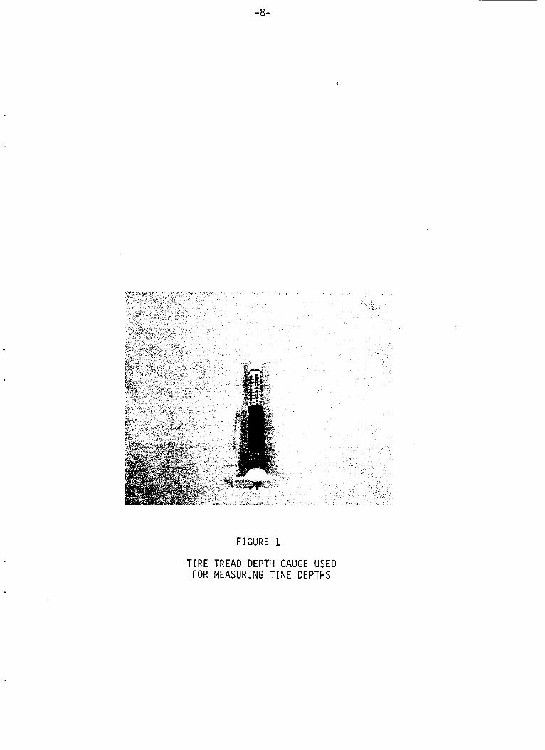
(see Figure 11, incremented in thirty-seconds of a n inch, turned ou t to be t h e
ideal tool for measuring the depth of tining on hardened deck concrete . On a
tined surface, t h e base of t he gauge rests on t h e upper asper i t ies of t h e surface,
while t h e probe is inserted into t h e groove. The scale shows t h e depth of t h e
groove in thirty-seconds of a n inch.
5.2.2 Sampling Plan
A random sampling plan was hen devised f r t h e bridge decks
selected for study. First, t h e bridge deck was divided in to 10, 15, or 20 equal
areas depending on the size of t h e deck and t h e number of individual slabs per
deck. Within each area , a three-foot by three-foot test site was laid out , using a
-a-
m
F I G U R E 1
T I R E TREAD DEPTH GAUGE USED FOR MEASURING T I N E DEPTHS

-9-
random selection procedure. A straightedge was then laid across t h e diagonal of
each test site, and t ine depths were measured and recorded at t en equally spaced
intervals along the diagonal.
5.3
In order to determine the minimum as-constructed depth of tining required
to provide a skid resistant surface throughout t he expected service l i fe of a
bridge deck, one assessment of t h e approximate loss of depth with t ime must be
made. Random measurements of t ine depth were made on twelve older bridge
decks on Route 78 (7 years old, 5 years under traffic). Since no da ta was
available for t h e as-constructed depth of tining, data was also collected on the
shoulder of t h e bridge decks to be used as a n approximate value for t h e tining
prior to t r a f f i c wear. Original skid test values were available for these decks
and skid tests were repeated this past summer for purposes of comparison.
Evaluation of Texture Wear Ra te s
6.0 RESULTS
6.1 Inspection Survey
6.1.1 Fac tors Investigated
Several bridge decks were observed during construction; Route 287-
3M,2L (Easton Canal), Route 195-1A, IE, and IOD (Route 2061, and Warrenville
Road Bridge. Several decks were inspected shortly a f t e r construction; Route
295-76 (Arena Drive and Kuser Road), and Route 78-4V, 5BM (Glenside Road),
and Route 287-3M,2L (Weston Canal).
Research and Construction personnel col laborated in order to make general
assessments of t h e quality of workmanship demonst ra ted by Contractor forces
responsible for t h e tining portion of t h e deck construction. Likewise, the quality
of t h e resul tant tining was also subjectively rated on a four-point scale f rom

-10-
excellent to bad. Factors which were considered in this assessment were
uniformity of tining, portion of deck without texture, portion of deck having
tears or pulls, and general appearance. It was hoped that the entire range from
excellent to bad tined decks would be identified, so that when the tine depth
measuring phase of the study was undertaken, a determination of the average
tine depth for a good job, poor job etc., could be made.
6.1.2 Quality of Workmanship
In the opinion of the Bureau of Construction evaluation team on each
of the bridge deck finishing operations observed in this study, the quality of
workmanship was "Good"; tha t is, the workmen were performing the tining
operation in accordance with specifications. The one exception to this was t h e
Warrenville Road bridge, where workmanship was rated "Excellent"; t h a t is,
exceptional effort was made to ensure a high-quality tined finish.
The opinion of the Research personnel, having admittedly less experience
with bridge deck finishing operations, was that in each case observed, except t h e
Warrenville Road job, little effor t was expended by the contractor to achieve the
specified tine depth. I t appeared tha t tining took place at a specified t ime (i.e.,
a fixed distance behind the finishing machine), regardless of the plasticity of the
concrete. In one particular case, the latex-modif ied concrete appeared
extremely variable, from truck-to-truck, and no effort was made to delay or
hasten , the tining operation to account for the material variation. Since "timing"
is the key to lltiningll, this would seem to indicate a lack of appropriate concern
or proper judgment. Pulling the t ine rake across the surface seemed to be
considered less important than applying the burlap covering, which was usually
accomplished as soon as possible, regardless of the concrete being set enough t o
support the burlap without adhering. In some cases, the burlap became
embedded in the finished deck, completely flattening the tined finish.

-11-
The mater ia ls and techniques used in bridge deck construct ion also
a f f e c t s t h e quality of tining achieved. Table 1 shows t h e mater ia ls , slump, air
and any special notes for each of t he bridge decks under study. The da ta for
slump and percent a i r on latex-modified concre te decks indicates t h a t most of
the mixes were at the high end of the specification; six inches slump, six percent
air.
6.1.3 Quality of Tining
Two bridge decks were rated "Good" - Route 295-7C (Kuser Road)
and Warrenville Road Bridge. A "Good" rating indicated t h a t t h e tining appeared
relatively consistent throughout t he deck; t he t ines appeared s t ra ight and deeper
than usual. Few a r e a s where the tining rake had only scratched t h e surface or
had torn the concre te were present. Two decks, Route 195-lA, lE , and 10D
(Route 206 North and South) were ra ted "Fair". Route 295-7G (Arena Drive)
North and South was rated "Poor". The tex ture was not deep and was fairly
inconsistent with a number of very shallow areas. Route 287-3M, 2L (Weston
Canal) and Route 78-5BN (Glenside Road) were ra ted llBadll. The Weston Canal
Bridge exhibited severe tearing, due to tining a f t e r t he conc re t e had begun to
set. Many areas were observed with very shallow tining; several areas had burlap
embedded in t h e surface.
The Glenside Road Bridge exhibited little to no tining in many areas , with
burlap embedded in several places. It was reported t h a t a sudden rainshower
during construction necessitated premature covering with burlap and
polyethylene. The weight of these materials, in conjunction with the rainwater ,
worked to f la t ten the tined texture.

TABLE 1
MTERIALS DATA ON BRIDGES OBSERVED I N STUDY
~~~~
287-3Hq 2L UESTON CANAL TYLAC LMC 5.3 6.0 w x 6.3 0-6.5 Excessive tearing of concrete. POLYSAR LHC 3.4 6.0 rax 5.1 0-6.5 Only used i n gutters.
287-3Hs 2L EASTON CANAL TYLAC LMC 4 6.0 aax 9.0 0-6.5 Shutdown when a i r reached 14%. POLYSAR LHC 5.3 6.0 max 5.5 0-6.5 Deck completed rr i th POLYSAR.
195-1AqlE RTE 206 NORTH A 2-3 1-3 5.4-7.0 4.5-7.5 Tining o f decks accomplished 1GD RTE 206 SOUTH A 2-3 1-3 5.1-6.6 4.5-7.5 by only one workman.
295-7C KUSER RD. EAST B 3.2 1-3 5.9 4.5-7.5 Vibratory pan used on 295-7C KUSER RD. WEST B 3.2 1-3 5.9 4.5-7.5 f in ish ing machine.
UARRENVILLE ROAD BRIDGE B1 3.2 1-3 5.0-6.0 4.5-7.5 Concrete pumped and hand f i n - ished w i t h vibratory screed.
,

-13-
6.2 Tine Depth Results on New Decks
Tine depths were measured with t i re t read depth gauges, using a
random sampling plan on a number of new bridge decks. These resul ts a r e
presented in Table 2. Distribution of t he t ine depths a r e presented in the
histograms in Figure 2 and Figure 3.
All of the bridge decks, except t he Weston Canal Bridge on Route 287,
averaged from 2.4 to 3.4 thirty-seconds of a n inch -- none m e t t h e cur ren t
specification of 1/8 inch minimum. The Weston Canal Bridge was measured to
average 4.1 thirty-seconds of a n inch; 66% of t h e measurements taken on th i s
deck were within specifications. However, due to t h e fragi le appearance of
these t ines (concrete tears), it is not expected t h a t this re la t ively good average
t ine depth will last very long under t raff ic .
An analysis of var iance was conducted for all t h e new decks under study,
excluding the outlier da t a f rom the Weston Canal Bridge on Route 287. Although
a significant difference was found to exis t between each of t h e seven bridges, no
distinction was found between latex-modified conc re t e and portland cemen t
concre te bridge decks as a group. Therefore, t he d a t a represents non-
homogeneous population which cannot be analyzed as one d a t a set, within t h e
parameters of Itgood" statistics.
However, for discussion purposes, it has been observed t h a t t he mean t ine
depth for all seven bridges is 2.8/32 inch with a s tandard deviation of 1.2/32
inch. Likewise, t he study indicates t h a t 79% of t h e measurements taken were
less than one-eighth inch and 80% were o u t of specification ( l /P to 3/16"). In
point of fact, even on the Warrenville Road Bridge, considered by bridge deck
inspectors to represent one of t h e best tining jobs in the i r experience, 67% of t h e
measured da ta fe l l below one-eighth inch.
As a comparat ive note , even if t h e average t ine depth achieved was
normally distributed about t h e specified mean (5/32 inch), t h e variability of t ine

-14-
TINE KPM MEAsvilwENTS ON NEW BRIDGE DECKS
CONTRACT LOCATION
295-7C AR!?ih DR. SOUK 295-7C ARENA DR. NORM 287-3U92L WESTON CAMAL 195-1AilE RTE % NORTH
10D RTE 206 SOUTH 295-7C KUSER RD. EAST 295-7C KUSER RD. UEST UARRENVILLE ROAD BRIDQ
B R I E
-- 78 w u 78 w #5 78 W 16 78 w Y7 78Wp8
78 E #2 78 E #3 78 E #4 78 E 85 78 E #b 78 E 118
1 s t l 1 s 12 195 W tl 195 u Y2
TYPE OF CONCRETE -
LMC LMC MC
A A
B B1
a
TINE DEPTkS (1132 in) RANGE llEAN STD.DRI.
0-7 2.9 1.2 0-5 2.6 0.8 0-9 4.1 1.6 0-6 2.9 1.4 1-6 3.1 1.2 0-8 2.6 1.0 0-5 2.4 1.2 1-8 3.4 1.4
TABLE 3
DURABILITY OF TINED BRIDE DECKS
AVERAGE TIM DEPTH OUTSIDE LANE SHOUUIER 1/32 in 1/32 in
2.2 3.8 2.5 4.2 2.2 3.4 2.0 3.4 2.5 2.4
-
1.3 3.0 2.1 2.7 1.6 2.0 2.1 3.3 2.2 2.4 1.3 2.9
1.2 2.7 1.3 2.5
2.3 4.5 2.2 4.1
x ( 1/8'
72.0 88.0 35.5 66.0 66.7
89.0 bb. 7
--
ma
ESTIHATE OF AVEME E A R SINCE CONSTRUCTION
1/32 in
1.6 1.7 1.2 1.4
-0.1
1.7 0.6 0.4 1.2 a. 2 1.6
1.5 1.2
2.2 1.9

-15-
5 0
5 4 0 - z
FIGURE 2
-
DISTRIBUTION OF TINE DEPTHS - P C C DECKS Percent o f measurements cur rent ly within
N. J. D.O.T. S p e c i f i c a t i o n s
195 - IA, IE, IOD
RTE 206 NORTH
g 4 0 z W 3 3 0 O W
E 2 0
10
0 0 1 2 3 4 5 6 7
!/32 i nc h
295 - 7C
KUSER RD. EAST
lot
195 - IA , I E , IOD
RTE 2 0 6 SOUTH
n 0
0 - 1 2 3 4 5 6 7 !&inch
295 - 7C
KUSER RD. WEST
r
10
0 0 1 2 3 4 5 6 7 0 9 0 1 2 3 4 5 6 7
!/32 inch 9s2 i n c h
WARRENVILLE ROAD BRIDGE 50r
1 2 3 4 5 6 7 8 9

-16-
100
90
80
7 0
6 0 - * W 3 W " 5 0 -
- - - -
FIGURE 3
DISTRIBUTION OF TINE DEPTHS - LMC DECKS Percent o f measurements c u r r e n t l y w i th in
N. J.D.O.T. S p e c i f i c a t i o n s
100
90
8 0
7 0
6 0
> 0
3 : 5 0 - a
4 0 iL
3 0
2 9 5 - 7C ARENA DR. SOUTH
- - - - -
- -
n
7 0 r
6 0 > g 5 0 - W 3 4 0 - 0 W
3 0 -
20
10
0
0 1 2 3 4 5 6 7 8
1/32 inch
-
-
- r/@Ej 4 ' I I 1 1 I 1
2 9 5 - 7 C ARENA DR. NORTH
0
0 1 2 3 4 5 6 1/32 inch

-17-
depths are such tha t 20% of this hypothetical bridge deck would be below the
minimum required depth and 40% would be ou t of compliance on both ends of t h e
specification.
6.3 Wear Ra te s on Tined Surfaces
6.3.1 Tine Depth Measurements
For this portion of t he evaluation, twelve LMC bridge decks on Route
78 constructed in 1978-79 were measured, using a random sampling technique.
Since no da ta was available for t ine depth at construction, measurements taken
on t h e shoulder were assumed t o be representat ive of the original tining. These
results are presented in Table 3; histograms shown in Figure 4 show the
distribution of average t ine depths for all of t h e westbound and eastbound decks.
If t he assumptions a r e made t h a t t ine depths will continue to decrease at
t h e same rate as it has for the f i r s t f ive years under t raff ic , and t h a t t he l i fe of
t he bridge deck is twenty years, at which t ime zero t ine depth is acceptable ,
then t h e minimum required t ine depth for a 63,000 AADT roadway with six
t r a f f i c lanes (outside lane assumed to be 6300 vehicles per day) would be 4.4/32
inch. Table 4 shows t h e t ine depth needed to ensure twenty years of service if
these da t a were extrapolated. 4
In order to check these assumptions, two additional latex-modified
concre te bridge decks were measured, t h e Pulaski Skyway (Route 1 SB) and
Route 195 WB over Route 130. These two bridges were redecking jobs; t he
Pulaski Skyway was reopened in September, 1980 and Route 195 in September
1982. Summary t ine depth measurement da t a is presented in Table 3 and
illustrated graphically in Figure 5.
After approximately 5.25 years of t r a f f i c (38,200 AADT), t h e average wear
r a t e was calculated to be 0.008 inches per year, very close to t h a t measured on

-18-
I30
120
110
too
90
* 8 0 -
w 7 0 -
w 6 0 -
50
40
3 0 -
0 2
3 0
K LL
I 3 0
t20[
- - - - -
- -
"i 90
10
40 c
I I I I
-
FIGURE 4
DISTRIBUTION OF TINE DEPTHS ON RTE.78 Percent o f measurements c u r r e n t l y w i th in
N.J.D.O.T. S p e c i f i c a t i o n s
R T E . 78 W. B. BRIDGES
r 2 0 301 I I
0 1 2 3 4 5 6 7
1/32 inch
R T E . 78 W. 8. SHOULDER
50 6o
401 30
I
0 1 2 3 4 5 6 7
'/32 inch
2 0 1
R T E . 78 E.B. BRIDGES
I 1
0 1 2 3 4 5 6 7
'/32 inch
0 1 2 3 4 5 6 7
inch
R T E . 7 8 E .B . SHOULDER

-19-
i- c o u z
4. a el 0 0
a = - v )
in m
W I-
z 0 cn I I- a W 0
W z I-
LL 0
z 0 I- 3
-
a
-
- m a
0
- I- cn -
- W + K
0 c c - c - 1 * c 0 L L 3 V
- e
a c c 0 s
: L 3 a 0
c 0
c c 0 u L a &
0 0 0 0 " (u. - h3N an03 tld
a
i 0 0 0 0 0 0 Y ) * m ( u -
h3N3l l03 t ld
0 0 0 0 0 0 I n * " "
A3N3l lO3t ld

-20-
Route 78 LO07 inches per year). Applying this wear ra te over the life of a bridge
deck yields the result that 5/32 inch of average tine depth would be sufficient a t
construction for this traffic level (see Table 4).
On the other hand, the data obtained from Route 195 indicated a much
higher wear rate, therefore, a greater average tine depth needed at construction.
This excessive wear ra te may be due to exceptionally heavy construction traffic
over this bridge deck during its 3.25 year life. A large amount of detritus from
this construction traffic was observed on the bridge during the survey. The
abrasive action of this material could lead to excessive erosion of the tined
finish. One other factor which may explain the high wear ra te on Route 195 is
the general appearance of the tined deck. The Route 195 bridge deck has a very
rough, jagged appearance, similar t o tha t observed on the Route 287 - Weston
Canal Bridge. This may be due to tining the surface a f t e r it had already begun
t o cure, leaving the surface torn and, therefore, more fragile.
Another factor to be considered is that the rate of wear on a bridge deck
may not be accurately described as a linear function of its age, but rather as a
logarithmic ra te of decline. If this were indeed true, then a "younger" bridge
deck like Route 195 would exhibit wear at a faster r a t e for some period of time.
Regular measures of average tine depth over the life of the bridge deck would be
required to confirm this.
Generally speaking, the results of this phase of this study, although
admittedly based much on estimate indicate that the tining wear ra te on these
"older" bridge decks (5+ years) is from 0.007 t o 0.008 inches per year. The data
presented in Table 4 indicate tha t at least one-quarter inch of texture depth is
required at construction for a bridge deck carrying 15000 vehicles per day per
lane, in order to provide sufficient skid resistance over a twenty year design life.

-21-
TABLE 4
T I N E DEPTH NEEDED TO ENSURE 20 YEARS OF SERVICE
VEHICLE PASSES PER T I N E DEPTH NEEDED LANE PER DAY AT CONSTRUCT1 ON ( i n )
5000 3/32 - 4/32 10000 6/32 - 7/32 15000 8/32 - 11/32
. 20000 11/32 - 14/32 25000 14/32 - 18/32
_----------------- -------------------
TABLE 5
RESULTS OF S K I D TESTS ON RTE 78 BRIDGES
ERIDGE NUMBER ------- WEST #4 WEST #5 WEST #6 WEST #7 WEST #8
1980 SN40
70 74 66 60 70
----
MEAN 70
1985 5n40
52 54 53 53 53
----
53

-22-
6.3.2 Skid Tests on Tined Surfaces
Skid tests (ASTM E-274) using a grooved tire were conducted shortly
a f te r construction on five of the twelve LMC bridges under study on Route 78
and repeated in July, 1985. These results a re presented in Table 5.
The results indicate relatively high skid resistance on the tined latex-
modified concrete bridge decks over the five-year period since they were opened
to traffic; decreasing an average of 16 SNs. It is difficult to make any
prediction of skid resistance durability on tined decks, using grooved tire skid
tests, since grooved skid tires a r e relatively insensitive to changes in perceived
skid resistance which occur with changes in texture depth. It is sufficient to
note tha t even at tine depths as low as 2.3 thirty-seconds of an inch, good skid
resistance is exhibited on LMC bridge decks.
7.0 ALTERNATIVES
Since the texture depths currently being achieved are considered
inadequate, there a re several alternate approaches which should be considered.
7.1 Improve Current Practice
Contractor and state personnel responsible for the tining operation
could be better educated as to the importance of the tining operation and its
long-term effect on the skid resistance of the deck. Preconstruction meetings
could serve as a forum for the discussion of the proper tining sequence and
procedures. The use of simple depth gauges, such as were investigated in this
study, would help insure that groove depth is adequate during the actual
construction process. Such checks would enable timely corrective action t o be
taken.
A stricter interpretation of the specifications and the possible use of
penalty clauses if textures did not meet the specified configuration could be

-23-
considered. Some limited equipment modifications might also be effective. For
example, s t i f fer t ines and longer t ines and t h e use of weighted heads on t h e
tining tool should result in deeper groove depths. However, t hese options do not
appear to of fer any real promise.
7.2 Mechanical Tining
Tining combs which a re mechanically moved transversely across t h e
bridge deck sur face while suspended under a truss similar to a finishing machine
f r a m e a r e routinely used to t ine concre te roadway surfaces. Some checking of
roadway surf aces, however, indicated t h a t these devices do not consistently
produce t ine depths which meet t h e specifications. Discussions with representa-
t ives of t h e equipment manufacturers indicate tha t a depth of 3/16 inch i s about
t he maximum tha t could be expected and would require optimum conditions, i.e.,
timing of application, concrete consistency, and concre te uniformity throughout
t he job. Observations indicate tha t these optimum conditions a r e unlikely to be
achieved consi st en tl y .
7.3 Artificial Turf Drag and Saw C u t Finish
The finish achieved by sawcutt ing should be much more consistent
than tha t which is achieved by tining because of t h e precise continuous control
of t h e depth of cut . Deeper initial t e x t u r e depths can be specified and achieved
thereby producing longer las t ing skid resistance. The sawcutt ing technique and
t h e resultant t ex tu re i s illustrated in Figure 6. Several added benefits c a n
accrue with the use of this option. Improved riding quality should be achieved
since t h e sur face imparted by t h e finishing machine would not be disturbed and
torn by the use of a tining tool. A t i m e constraint imposed upon t h e cont rac tor
by t h e requirement to begin tining a f t e r t h e water sheen has disappeared and
finish tining before t h e set has reached t h e point where tear ing or roughening of
the sur face will occur, would be eliminated.

-24-
F I G U R E 6
SAWCUTTING GROOVES I N BRIDGE DECK

-25-
Durability should be improved since the curing process could be s ta r ted
immediately without t he need to delay application of t h e polyethylene and burlap
until t h e tined tex ture would not be distorted by their application. Penetrat ing
sealers may penet ra te more effect ively when applied to newly sawed surfaces.
A disadvantage of this procedure would obviously be t h e added cost of t h e
sawcutting. Based on t h e New York State experience, t he cost of sawing would
be in t h e range of $1.00 to $1.50 per square foot initially. New York fee ls a
reduction to 0.30 to 0.45 cen t s per square foot is reasonable with increased use
of the procedures. La tes t bid prices in New York State were in the .65 to .75
c e n t range going up to $1.00 in t h e New York City area.
8.0 CONCLUSIONS
1. An examination of the data collected on various bridge deck sur faces
during this study indicate t h a t t h e cur ren t specification of 1/8 to 3/16 inch of
t ine depth is not being achieved. Even on the Warrenville Road project, which
was considered to be t h e most sat isfactory t ine finish observed by, Bureau of
Construction personnel in two years of in-depth inspections, t h e measured t ine
depths on t h e bridge deck were substantially less than t h e required minimum.
2. A preliminary study of tex ture wear r a t e s on bridge decks indicates
t ha t even grea te r tex ture depth than is current ly specified is needed to maintain
a skid resis tant surface over t he bridge deck life. The results of this study show
t h a t o n e q u a r t e r inch of tex ture would generally be sufficient to m e e t this
criterion.
3. The tire depth gauge is a simple, inexpensive, and relatively accu ra t e
tool for t h e determinat ion of t ine depths in t h e field during construction.
Texture depth in itself is not a sufficient measure of t h e quality of final finish on
a bridge deck surface. Interpretat ion of t h e resul ts must be tempered by

-26-
engineering judgment. Such fac tors as uniformity of finish, tear ing and gouging,
and durability of t he final product must be considered.
4. The results of t he questionnaire sent ou t to all the states indicate
t h a t tining is a problem nationwide. Dissatisfaction with t h e quality of tining
typically achieved is universal, indicating t h a t new methods for textur ing bridge
decks a r e in demand.
5. One option suggested to improve tining quality is t h e use of machine-
tining equipment. However, since states which specify machine-tining are by
and la rge dissatisfied with their results, and since even t h e equipment
manufacturers are not optimistic, t h e use of machine-tining equipment does no t
s eem to of fer much promise at present.
6 . The only procedure which has consistently produced sat isfactory
results is t h a t current ly specified in New York State -- sawcutting. New York
S t a t e fee ls t h a t t he additional cost incurred by sawcutt ing is sufficiently of fse t
by t h e uniform, high quality t ex tu re achieved on their new bridge decks.
9.0 RECOMMENDATIONS
1. Sawcutting to a minimum depth of one-quarter inch is t h e
recommended procedure for bridge deck texturing. The use of this procedure
will ensure the uniform tex ture depth required to last the l i fe of t he bridge deck.
Sawcutting, in accordance with t h e Sample Specification included in
Appendix B, should be required in all bridge deck construction and rehabilitation
projects.
2.
3. In t h e interim, the use of t h e tire t read depth gauge is recommended
to be used by inspection personnel to ensure t h e best achievable t ine depth.

-27-
10.0 REFERENCES
1. FHWA Memorandum dated February 21, 1985 by John J. Kessler to Edward
D'Arcy, Chief, Bureau of Construction.
RD-83/107 "Decay of Tine-Textured Grooves in Rigid Pavements" John E.
Grady, New York Department of Transportation Report 1983.
2.
3. Transportation Research Record No. 652 "Texturing New Concrete
Pavements" Mahone, D.C., McGhee, K. H., McGee, J. G. G., Galloway, J.
E. 1970.
FHWA/IL/PR-82-095 "A Study of PCC Pavement Texturing Character is t ics
in Illinois" Dierstein, P. G., 1982.
"An Investigation of Frictional Properties on Wire Combed PCC Pavement
Surfaces" Missouri Highway and Transportation Department 1978.
4.
5.

-28-
APPENDIX A
RESPONSES TO QUESTIONNAIRE ON
CONCRETE TEXTURING

-29- QUESTIONNAIRE ON CSNCZETE TEXTURING
1. What type oi f ind dnish do you require on your concrete bridge deck or concre te roadway surr'aces?
Br idqes : T i n i n g 34 (79%) Grooving 16 (37%) E i t h e r 11 (26%)
Bur lap Drag 10 (23%)
2. If tining or grooving is specEtd, whai p a i t e m do you require (depth o i groove, groove spedng)?
Br idges : Maximum Depth: 1/4" ' 2 ' (5%), 3/16" 1 8 (42%),
1 /5" 2 (5%), 1/8" 12 (28%), 1 /26" 1 (2%), 1 /20" 1 (2%)
3. Do you sptcir'y a s?tcir'ic t y p z sf equipment or consiruction pramicn ( t ime of appiiczdon, sueI'ece z?perrzxt, ex. ) in order to insure t h a i you a r e L C U ~ ! ~ go-zing i k e &sire:! corEZxztion?
Other (47%) - Surface Appearance 9 (21%)
T ine Dimensions .. . 14 (32%)
4. In view of t h e variability of Eris>ir,g whidi will be encounieted under fie!d condidons, wher do you consider zn rcce?rabie job?
, Enqineer inq Judqment 14 (32%)
Conformance t o Spec i f i c a t i o n s 13 (30%)
5 . DO you ;xr iorm zny i t s t s t i ther dcrino or g i c r construciion TO check the t e z u r t dt?:S a d pzi;?rn? If 55, *;.auk ycu cesc:ibe the prcceaure or t e S i S
wni& you cx p r i o r m i n g .
0
Visua l I n s p e c t i o n 19 (44%) Depth Gauge 9 (21%)
Sand Patch 6 (14%) Reference B locks 3 (7%.)
Concrete T e x t u r i n g P r a c t i c e s 1985
Number o f . s t a t e s responding: 43 (86%). The l a r g e response t o t h e ques t i onna i re i s i n d i c a t i v e o f t h e concern na t i onw ide r e l a t e d t o t h e problem of ach iev ing adequate su r face t e x t u r e on concre te and more s p e c i f i c a l l y b r i d g e deck t r a v e l l e d ways.
Responses t o t h e va r ious ques t ions are summarized above and t a b u l a t e d i n the a t tached t a b l e .

STATE W
kYABMi4 ALAsI(A A R I Z W ARK4NsAs CALIF. 118 COLORADO CONN. DELAUARE FLORIDA GEOR61A 118 twnI I IDAHO I L L I N O I S I N D I l w A IOWA X
KANSAS KENTUCKY LOUISIANA M I N E M R Y L A N D 118 HI@ HICHIGAN nIw nrss HISSOUR1 M W NEBRASKA x "ADA N.WP x N.JERSEY N . E X I C O 118 N.YORK 1/18 N. CAROL. N. DAKOTA OHIO OKLAHOWA OREW PE" R . I W 3/16 s. CAROL. S . DAKOTA TENNESSEE 118 TEXAS 118 UTAH X
V E M x V I R G I N I A w. W.VIR6. WISCONSIN UYOHIN6
'.
-30-
B R I D E S
Grooving S D W
Tininq S
314 3116
314 1 I8
X X
518-718 3/16
X X
X X
718 3116 314 114
314 3/16 3/8-34 118 314-1 118 118-314 118 114-112 1/28 X X
X X
518-918
X X
4 I 8 314
1/32 112
3132 314
1110-118 314
1/8-3116 314 3116 314
118 1 12 113-1
X X
118 112 1132 1 112
1110-118 112 5164 314 118 112-314
1/10-118 112-314 5164-118 718
5164-118 112 118 112-1 1/18 518 5164-118 112-1 118 314
3/16 314 110 1 12
3132-118 113-1 118 114-1 12 118 112-314
X X
118 314 1 I8 1 12 3132 112 118 1
D W
1 /B
X
3/16
3116
3116
3/16 x
118-3116 x 118 118-1 15 118-3/16 x X
Drag S D
X X
X X
X X
118 31 16
118 118-3116 118 X X X
X X X
1/6-31 1 b .18
5120-114 118-3116 3120 X
118-114 118-114
3116 1 I 8
118-115 x 1/20 1/8
118 3/16 1l8-3l1 b 118-3116
X X
X X
X x X X

-31-
BRIDGES
STATE GI
ALABAllA A L A S K A X ARIZONA A W CALIF. COLORADO Co". DELAWARE FLORIDA GEOR61A W I I IDAHO x ILLINOIS INDIANA I OM X KANSAS mcKY LOUISIANA M I I S M R W IlASs HICHI6QN HI" HISS x MISSOURI tloNTANA NEBRASKA x NEVADA N.tWlP X N. JERSEY N. HEX ICO N. YORK N. CAROL. N. DAKOTA OHIO OKLAHOnA ORE6ON PE" R. ISLAM) s. CAROL. s. DAKOTA TEFEESSEE TEXAS 118 UTAH VEm x VILINIA WASH. W.VIR6. UISCONSIN UYMIN6
Brcor S
X
X
X
X
X
X
314-1
114-1 I2
X
Others D W S D
X
X X X
1/16 1/32-3132 1 I2 3/16
110
1/28
X

-32-
PAVMMTS
STATE Crooving Tining Drag Broom W S D w s D W s D W S
AMAH4 ALASKA ARIZONA ARKANSAS CALIF. COLORADO co". WAWARE FLORIDA GEOffiIA HAUAI I IDAHO ILLINOIS INDIANA IOWA X
KANSAS KENTUCKY LOUISIANA M I X ElARyLAND w H I C H I W
HISS
mANA MBRASKA NEVADA N. t M P N.JERW N.KXICO N. YORK N. CAROL. N. DAKOTA OHIO oKlAHoM OAE6ON PE" R. ISLAND s. CAROL. %DAKOTA 118 TENNESSEE TEXAS UTAH VERtlONT VICINIA w. W.VIR6. WISCONSIN wYOnIN6
nIra
n I w R I
1 I32 112 3/16 1/32 112 3116
118 112 1164-118
112 1/1%1/8 314 3/16 X X X
118-3116 314 118-3116 x X X X 3/16 114 118
X
1 I8 1 I2 118-3116 x X x
1110-318 112 118 5/64 314 3/4-3116 X X X
l/l0-1/8 112-314 118-3116
31 16 5164- 118
5164- 118 X
X
314 3/16 I8 112 3120-114
112-1 118-3116
I8 112-1 118-114 314 118-114 X X
X X X x . X 3132-118 113-1 118-115 3/32-5164 1 1 18-31 16 118 518-718 3/32-5132
1 I 8 112 3/16
118 1 1/8-3116 118 1 118-3116
314-1

-33-
PAVEMENT EQUIPMENT E S T S
6auge S T A T E llachine Hand Other Sandpatch Depth Other
X
/ L A B A H A X X
AlAW ARIZONA x A R W A S : C A L I F . x COLORADO CONN. x DELAWARE FLORIDA GEOR61A x HAW1 I IDAHO I L L I N O I S x X
INDIAN44 IOWA X X
K A N S A S X KENTUCKY X
L O U I S I A N A x X
M I N E M R Y L A N D x MSS MIMIW HI" X
H I S S X
H I S S O U R I MONTANA x NEBRASKA x NEVADA N . W P N.JERSEY x N . K X I C 0 N.YORI( x N. CAROL. N. DAKOTA OHIO X
O W M x OREGON PE" R . I S L A N D x S.CAR0L. S. DAKOTA TENESEE x TEXAS x UTM X
E r n V I R 6 I N I A w. x W. V I R 6 . WISCONSIN x U Y O n I N 6
X
X
X
X
X
X
X
X
X
X
A
X
X
X
X
X
X
x
X visual
visual X X
X X
X visual X
X
visual
visual X visual X
X
visual
visual visual
visual X dial-type
X
X
visual
visual
visual visual
visual
X
X
visual visual visual visual

STATE
ALABAMA ALASKA ARIZONA ARKANSAS CALIFORNIA COLORADO CONNECTICUT DELAWARE FLORIDA GEORG I A HAWAII IDAHO ILL INO I S INDIANA IOWA KANSAS KENTUCKY LOUISIANA MA I NE MARYLAND MASSACHUSETTS MI CHI GAN MINNESOTA MISSISSIPPI MISSOURI MONTANA NEBRASKA NEVADA NEW HAMPSHIRE NEW JERSEY NEW MEX I CO NEW YORK N. CAROL I NA N. DAKOTA OHIO OKLAHOMA OREGON PENNSYLVANIA R. ISLAND
S. DAKOTA TENNESEE TEXAS UTAH VERMONT VI RGIN I A WASHINGTON W. VIRGINIA W I SCONS IN WYOMING
S. CAROL I NA
-34-
COMMENTS
Most bridges have a. c. wearing course. - Deck coefficient of friction >or= 0.3 after finish. Deck is usually a.c. over membrane
No tining problem if concrete is good quality Silicon reference sample Reference blocks define texture depths Hand tining permitted on bridge decks
Hand tining permitted on bridge decks Finned float used for tining decks
Stiff bristle texturing mat
Deficiencies corrected by sawing Deficiencies corrected by sawing Belt finish
Skid tests used as control Broom finish permitted on decks
Membrane used with bituminous overlay Hand tining primarily on bridges
Spec pending change to 100 X saw grooving
Ruler and straightedge used to check tine depth Flexi-guide tine used Hand tining permitted where mechanical cannot be used
Grind and groove to correct deficiencies Large decks are sawcut
Tining to be specified in near future
Test panels used to train inspectors
Turf drag in urban areas, tining in rural.
-35-
APPENDIX B
SAWCUT GROOVED DECK FINISH SPECIFICATION

- -36-
501.15 Deck Slab Surface Texture Finish. The surface of the deck slab shall
be finished in accordance with Subsection 405.13 except that part (g) shall not
apply. All concrete bridge deck slabs shall be textured with an artificial turf
drag and shall be sawcut groove finished.
(a) Turf Drag. Immediately after finishing has been completed, t h e
surf ace shall be given a texture with an approved artificial turf drag. The drag
shall be made of molded polyethylene with synthetic turf blades approximately
0.50 inches long. There shall be approximately 6,000 blades per square foot.
The drag shall be operated in a longitudinal w transverse direction. Once
begun, the direction of texturing shall not change. Texturing shall be done from
a work bridge.
When texturing is done in the longitudinal direction, t h e turf drag shall be a
single, full-width strip. Small areas otherwise inaccessible to t h e full-width drag
may be textured by hand methods.
The turf drag finish shall be applied so as to prevent ridges or gouges from
forming in the concrete surface. The drag shall be weighted and t h e contact
area changed as required to produce a uniform texture. The drag shall be
cleaned periodically to remove all hardened concrete particles. Texture
resulting from the drag shall s top within one foot of curbs.
(b) Sawcutting. The bridge deck concrete shall be cured in accordance
with Subsection 405.14. Sawcutting shall not be permitted until the concrete on
the deck has attained a strength of at least 3000 pounds per square inch as
determined from cylinders cast during t h e placing of t h e concrete deck and is at
least 14 calendar days old. Unless otherwise approved, sawcutting shall be
completed prior t o opening to traffic.

-37-
(c) Sawcut Grooved Surface. The hardened surface of concrete bridge
deck slabs shall be grooved except at t h e locations shown in Table 501-A.
A plan of action shall be submitted for approval, seven days prior to
sawcutting, detailing the layout of t h e grooving procedure to be followed.
Spacing dimensions at the starting and ending point of each pass shall be noted.
A description of the sawcutting equipment shall be included.
Grooves shall be cut perpendicular, or radial, t o t he centerline of t he
roadway. Radial grooving shall be conducted in partial width passes. Each pass
shall be limited to one lane width. Adjustment along the longitudinal axis of the
bridge deck shall be made at no less than twelve foot intervals, yielding a
uniformly grooved surface finish.
Grooves shall be rectangular in shape. They shall conform to the following
dimensions:
Width ............... .Ill to .W
Depth ............... .2Y1 to. .3 75"
Grooves shall be spaced at 1.5" plus or minus .0625" center-to-center of
groove. This spacing dimension may be increased up to 3" at t h e end of each
consecutive multiple bladed saw cut pass as necessary to accommodate the
distance tolerance required at the joint system (see Table 501-A). The required
dimension will be determined prior to actual deck grooving and shall be stated in
the plan of action. The cutting of grooves over an area which has already been
grooved will not be permitted. N o cutt ing blade shall be introduced into an
already established groove. When it is necessary to rotate t h e sawing equipment
to complete grooving to within the tolerances specified in Table 501-A, t h e
longitudinal gap created shall not be located in a wheelpath and shall not exceed
3" in width.
Grooves shall terminate within the following limits.

Location
-3a-
TABLE 501-A
Closest Allow- Farthest Allow- able Distance able Distance
Drainage Structure 1' - 0" 1' - 3"
Vertical face (curb or parapet), or face of railing (no curb)
Joint System 6" See Note
Note: This distance is a variable which is dependent upon e qu pm ent size . This dimension shall be measured perpendicular to the direction of the grooves. The distance shall be measured from the edge of the joint system and in no case should be greater than t h e width of t h e saw head plus nine inches tolerance.
-
Grooves shall be constructed using multibladed sawcutting equipment,
f i t ted with diamond-tipped circular saw blades, except when t h e Engineer
permits t h e use of single blade circular saw equipment where he determines such
equipment is necessary to complete t h e work as required.
Prior to grooving operations, the Contractor shall supply two approved
gauges to verify groove depth. The gauges shall be accompanied by
manufacturer's instructions fo r their use.
During the grooving operations, the groove dimensions will be checked at
random. If the minimum groove depth.is not being achieved, t h e Contractor
shall stop grooving operations and make necessary adjustments.
Slurry from t h e grooving operation shall not be permitted to accumulate in
the grooves. Slurry or debris shall not be disposed of in the structure or highway
drainage system nor on the roadway slopes. Slurry shall be promptly collected
and removed for disposal off-site.
Sidewalks and top of curbs shall receive their final finish with a fine
bristled broom.

-39-
50 1.25 M e t hod of Measurement
The following is added:
The sawcut grooved deck surface will be measured by the square foot
of deck, less the ungrooved gutter areas.
501.26 Basis of Payment
The following is added:
Pay I tem
Sawcut Grooved Deck Surface
Pay Unit
Square Foot

-40-
Add t o 405.03 Equipment af ter (f)
Multibladed Circular Saw: When sawcutting grooves is specified, sawing
equipment shall be provided. The saws shall be of a multibladed type, adequate
in number of units and power to complete the sawcut grooving operation,
equipped with water-cooled, circular, diamond edge blades and alignment wheels.
A system of slurry collection shall be provided. An ample supply of replacement
saw blades shall be maintained at the work site at all times during grooving
operations.