OF LATERAL PRESSURES DUE TO K WAY ... · A Study of Lateral Pressures on Basement Walls Due to ......
98
Al"I 423 A STUDY OF LATERAL PRESSURES ON BASEMENT' MALLS DUE TO 1/1 SNELLING SOILS(U) TEXAS TECH UNIV LUBBOCK DEPT OF CIVIL ENGINEERING W K WAY SEP 5? MES/CR/GL-U7-5 UUCLOSSIFIED F/G 13/13 ML EnhMhhhhhmh mhhmhmhhhhmmhl mmhhhmhhhhhhhl Ehhhhhhhhhhhml mhhhhhhmhmhhml I-EhhhEEEEE-|
Transcript of OF LATERAL PRESSURES DUE TO K WAY ... · A Study of Lateral Pressures on Basement Walls Due to ......

Al"I 423 A STUDY OF LATERAL PRESSURES ON BASEMENT' MALLS DUE TO 1/1SNELLING SOILS(U) TEXAS TECH UNIV LUBBOCK DEPT OF CIVILENGINEERING W K WAY SEP 5? MES/CR/GL-U7-5
UUCLOSSIFIED F/G 13/13 ML
EnhMhhhhhmhmhhmhmhhhhmmhlmmhhhmhhhhhhhlEhhhhhhhhhhhmlmhhhhhhmhmhhmlI-EhhhEEEEE-|

' N
Nis.
"'12.0- M4i
4%4
4N
• ' • 0 .,O . • , • • • • • t • -.
• • =w v" ' " - ' , . W- % p .=, •" .a' .=.% % .% . % % = % . .,,=

IC~~ FIE~?NTRACT REPORT GL-87-5
A STUDY OF LATERAL PRESSURES ONi -- BASEMENT WALLS DUE TO SWELLING SOILS
by IWarren K. Wray
4 ' "Department of Civil EngineeringTexas Tech University
', Lubbock, Texas 79409
AA
September 1987
Final Report
' Approved For Public Release, Distribution Unlimited
DTI
-- '" °
US Arove Fngner PubicReeras D xstribtoimedtSain
PVMiELECTESOCT 2 21987 '21
Prepared tor DEPARTMENT OF THE ARMYUS Army Corps of EngineersWashington, DC 2031 4-1000
It Monitored by Geotechnical LaboratoryL US Army Engineer Waterways Experiment StationLADOR TPO Box 631, Vicksburg, Mississippi 39180-0631

Unclassified ,
SECURITY CLASSIFICATION OF THIS PAGE.-,
Form ApprovedREPORT DOCUMENTATION PAGE OM No 0704-0188
£_EN Date Jun 30. 1986la REPORT SECURITY CLASSIFICATION lb RESTRICTIVE MARKINGS
Unclassi fied2a SECURITY CLASSIFICATION AUTHORITY 3 DISTRIBUTION/AVAILABILITY OF REPORT
Approved for public release; distribution2b DECLASSIFICATION IDOWNGRADING SCHEDULE unlimited.
4 PERFORMING ORGANIZATION REPORT NUMBER(S) S MONITORING ORGANIZATION REPORT NUMBER(S)
Contract Report GL-87-5
6a NAME OF PERFORMING ORGANIZATION 6b OFFICE SYMBOL 7a NAME OF MONITORING ORGANIZATIONDepartment of Civil Engineering (f applicable) Geotechnical LaboratoryTexas Tech University USAEWES6c. ADDRESS (City, State, and ZIP Code) lb ADDRESS (City, State, and ZIP Code)
Lubbock, TX 79409 P0 Box 631Vicksburg, MS 39180-0631
Ba NAME Of FUNOINGISPONSORING 8b OFFICE SYMBOL 9 PROCUREMENT INSTRUMENT IDENTIFICATION NUMBERORGANIZATION (if applicable) ,
US Army Corps of Engineers , pibl
Sc. ADDRESS (City, State, and ZIP Code) 10 SOURCE OF FUNDING NUMBERS
PROGRAM PROJECT TASK WORK UNITWashington, ELEMENT NO NNO O ACCESSION NO
II TITLE (Include Security Classification)
A Study of Lateral Pressures on Basement Walls Due to Swelling Soils
12 PERSONAL AUTHOR(S)
Wray, Warren K.13a TYPE OF REPORT 13b TIME COVERED 14 DATE OF REPORT (Year, Month, Day) 15 PAGE COUNT % %
Final report FROM TO September 1987 9716 SUPPLEMENTARY NOTATION
Available from National Technical Information Service, 5285 Port Royal Road,Springfield, VA 22161.
17 COSATI CODES 18 SUBJECT TERMS (Continue on reverse of necessary and identify by block number) C S
FIELD GROUP SUB GROUP Retaining wallsExpansive clays
19 ABSTRACT (Continue on reverse if necessary and identify by block number)
.A study was made of the technical literature pertaining to the topic of lateralpressures transmitted to nonyielding, rigid basement walls by swelling expansive soils. "i.lw,The objective of the study was to determine if there was available a method wherebypressures transmitted to rigid basement walls could be practically and reasonably pre-dicted for design purposes. An extensive bibliography of pertinent technical publica-tions was developed. The publications which formed the bibliography were topicallycategorized as being either principally theoretical or principally experimental in theirpresentation or result. Selected publications of each type are discussed, and theirprincipal findings are reported. Of these selected publications, three methods orprocedures were concluded to have more potential for practical applications than theothers and are presented in detail. These three methods or procedures are those ofSkempton, Fredlund, and Katti. The study concluded that these three methods were each
(Continued)
20 DSTR,8?JTON A'VALAR',ITY o AfS'R,:C' 21 ABS'RA(* S UP Y ( .A' , A N ( i
C LJ1ffLASS l;ED1),%E 'VTT) E] 4 AS DP' C3 D70 ( SI Unclassified12dt NAM E O itESPONSth Nr')%'b D . E 't .I .! I jnrI1 d a, Ca } 2.4 0we (of .i ,i
C. L. McAnear (601) 634-222, CEWES-GE
"1/
00 FORM 1473,8 %AMAR ,-=.:r, a '.d, -'~ . _ _ . ', ( .%,no.,". - _.
I 'fe' e '' ') ''" ' '1 1 '"telh ( a s, i t ied
#6.'"2

UnclassifiedSECURITY CLASSIFICATION OF THIS PAGE
19. ABSTRACT (Continued).
,-relatively easy to apply and held more promise than others for use in the design ofrigid basement walls constructed in expansive soils, but that none of the methodsappeared to have been proven, validated, or verified by field measurements of hori-zontal pressures transmitted to nonyielding basement walls. The study concludes witha recommendation to develop a field experiment whereby horizontal pressures can bemeasured and used to validate, modify, or reject the three methods.
'9'S
Unclai fied
o,'S.5 %,
PREFACE
This study was accomplished under an Interagency Personnel Agreement
(IPA) between the US Army Engineer Waterways Experiment Station (WES),
Vicksburg, Mississippi, and Texas Tech University, Lubbock, Texas.
The study was performed under the general supervision of Dr. W. F.
Marcuson III, Chief, Geotechnical Laboratory (GL), and Mr. C. L. McAnear,
Chief, Soil Mechanics Division (SMD), GL, and under the direct supervision
of Mr. G. B. Mitchell, Chief, Engineering Group, SMD, GL. Dr. W. K. Wray,
Texas Tech University, prepared the report. Ne%
COL Dwayne G. Lee, CE, was Commander and Director of WES during the
publication of this report. Dr. Robert W. Whalin was Technical Director.
%%
N9T fS G A&1 WDTIC TAB 0
A . ,
5i1l A I~C&
Ii{- -:- • , • ', . - • ,,.,, .,,., ". . ,. . . . ,'. ,.-,, ", ".% " ',' ",""." ',- % "%'",'','," ',, , N .'. ,w'w',' .1

CONTENTS
Page
PREFACE .. ... ....... ....... ...... ..........
LIST OF FIGURES. .. ..... ....... ....... ........ 3
LIST OF TABLES .. ...... ....... ....... ........ 4
ACKNOWLEDGEMENT. .. ..... ....... ....... ........ 5
PART I: INTRODUCTION .. ... ....... ....... ....... 6
PART 11: REVIEW OF THE TECHNICAL LITERATURE. .. ...... ...... 9
Theoretical Analyses. .... ................. ... ...... 9Experimental Results. .... ....... ...... ..... 20
PART III: METHODS FOR PREDICTING LATERAL PRESSURES INEXPANSIVE SOILS. ... ....... ....... .... 37
Skempton Method. .. ..... ....... ....... .... 37Fredlund Method. .. ..... ....... ....... .... 41Earth Pressure Equations for Saturated Soils .. ..... .... 43Earth Pressure Equations for Unsaturated Soils. .... ...... 46Katti Method .. ...... ....... ...... ....... 52
PART IV: CONCLUSIONS .. ...... ....... ........... 73
PART V: RECOMMENDATIONS. ... ....... ....... ..... 76
REFERENCES. ... ....... ....... ....... ....... 77
APPENDIX A: DERIVATION OF SELECTED FREDLUND LIMITEQUILIBRIUM EQUATIONS .. ...... ........... Al
Saturated Soils. .. ...... ...... ....... .... AlUnsaturated Soils. .. ...... ...... ........... A3
22

LIST OF FIGURES
No. Page
2-1 Relationship between measured lateral pressure and thickness ofbackfill. (After Ahmed, 1967) ................................. 23
3-1 Mohr's circle relationship for Skempton's method showingcapillary pressure and the effective stress in the specimenbefore shearing. (After Skempton, 1961) ........................ 38
3-2 Active and passive earth pressure for saturated and unsaturatedsoils. (After Pufahl, et al., 1983) ........................... 44
3-3 Active earth pressure for saturated soil conditions with zeroporewater pressure. (After Pufahl, et al., 1983) .............. 47
3-4 Passive earth pressure for saturated soil conditions with zeroporewater pressure. (After Pufahl, et al.. 1983) .............. 47
3-5 Active earth pressure for unsaturated soil conditions.(After Pufahl, et al., 1983) ................................... 49
3-6 Passive earth pressure for unsaturated soil conditions. %(After Pufahl, et al., 1983) ................................... 51
3-7 Measured lateral pressures with depth for cohesive nonswellingsoil (CNS) only, swelling expansive soil only, and swellingexpansive soil with various thicknesses of CNS between thewall and the expansive soil. (After Katti, et al., 1983) ...... 57 .9
3-8 Measured lateral pressures with depth for cohesive nonswelling -soil (CNS) only, swelling expansive soil only, and swellingexpansive soil with various thicknesses of CNS on top ofthe expansive soil (cover). (After Katti, et al., 1983) ....... 59
3-9 Measured lateral pressures with depth for cohesive nonswellingsoil (CNS) only, swelling expansive soil only, and swellingexpansive soil with various thicknesses of CNS both as coverand between the wall and the swelling expansive soil.(After Katti, et al., 1983) .................................... 60
3-10 Relationship between the reduction in measured lateral pressuresand thicknesses of cohesive nonswelling soil (CNS) either ascover or backfill between the wall and the swelling expansive %soil. (After Katti, et al., 1983) ......................... 62
3-11 Measured surface heave resulting from various thicknesses ofcohesive nonswelling cover soil (CNS) with and without anyCNS backfill between the wall and the swelling expansivesoil. (After Katti, et al., 1983) ............................. 65
3-12 Reduction of the calculated coefficient of at-rest earthpressure, K0, at selected depths with various thicknesses• 0of cohesive nonswelling soil (CNS) between the wall and theswelling expansive soil with and without CNS cover. (AfterKatti, et al., 1983) ......................................... 69
A-1 A typical soil suction profile with Fredlund's linear relation-ship simplification shown (Line dbc). (After Pufahl, et al.,1983) ....................................................... A4
3

LIST OF TABLES
No. Page
2-1 Comparison of capillary pressures calculated by three differentmethods. (After Skempton, 1961) ............................... 10
2-2 Soil properties. (After Skempton, 1961) ........................... 113-1 Properties of soils used in cohesive nonswelling soil tests by
Katti, et al. (After Katti, et al., 1983) ................... 543-2 Test series conducted in cohesive nonswelling soils by Katti,
et al. (After Katti, et al., 1983) ............................ 553-3 Measured lateral pressures with various combinations of
cohesive nonswelling soil (CNS) used either as cover or baas backfill between the wall and the swelling expansivesoil. (After Katti, et al., 1983) ............................. 56
3-4 Reduction in measured lateral pressures as a result of variousthicknesses of cohesive nonswelling soil (CNS) between thewall and the swelling expansive soil with and without CNScover. (After Katti, et al., 1983) ............................ 63
3-5 Measured heave resulting from various thicknesses of cohesivenonswelling soil used in various combinations of cover andbackfill between the wall and the swelling expansive soil.(After Katti, et al., 1983) ............................... 64
3-6 Calculated values of the coefficient of at-rest earthpressure, K , at selected depths resulting from variouscombination? of cohesive nonswelling soil (CNS) used ascover or backfill between the wall and the swellingexpansive soil. (After Katti, et al., 1983)............... 67
W",
4
°S
.. """.." ', % . %' . .'.. ...V..~

ACKNOWLEDGEMENT
This study was accomplished under an Interagency Personnel Agreement
(IPA) between the US Army Engineer Waterways Experiment Station, Vicksburg,
Mississippi, and Texas Tech University, Lubbock, Texas. The writer grate-
fully acknowledges the financial support and encouragement provided to him
by the US Army Engineer Waterways Experiment Station in conducting this
study.
5

PART 1: INTRODUCTION
1. Estimating lateral earth pressures has been a problem to civil
engineers since antiquity. The first to publish a rational approach by
which lateral earth pressures could be estimated was C. A. Coulomb. He
published his method in 1773 and 1776. His effort was followed by that of
W. J. M. Rankine in 1857.
2. These two methods differ in the assumptions made to simplify the
problem, but both are fairly simple in application and have subsequently
come to be known as the "classical" methods of solution for lateral earth
pressure. A number of other methods have been proposed since the
presentation of the Rankine method. Some of these methods are mathematical
in their approach and others are graphical solutions such as Poncelet Method
(1840), Culmann Method (1866), Trial Wedge Method (Bowles, 1982), and Loga-
rithmic Spiral Method (Bowles, 1982). The fact that so many other methods
of solution have been proposed since the presentation of the Rankine method
should alert the reader that none of the methods of predicting lateral earth .
pressure that have been introduced to date have been completely satisfactory
in general practice.
3. Each of the methods cited above has essentially a common basis,
i.e., either the structure supporting the soil moves away from the soil
mass and permits the soil to fail along a specified shear plane, or the
retaining structure is forced into the soil mass causing a shear plane to
occur. In the first instance, the soil is permitted to relax and strain
laterally as the soil moves outward, attempting to follow the structure as
it moves away from the retained soil mass. This straining condition is%
known as the "active" state or condition. The opposite condition, i.e., 1
when the retaining structure is forced into the soil mass, results in the
6
.0. 2 r- J

soil mass being compressed. If the force moving the retaining structure
into the soil is sufficiently large, it will cause the soil to fail in
shear. This straining condition is known as the "passive" state or
condition.
4. The active and passive states describe the two conditions when the
soil is being either stretched or compressed. When neither of these condi-
tions are occurring, the condition of the soil is said to be "lat rest." The
methods of predicting the lateral earth pressure cited above are applicable
to "conventional" soils. For the purpose of this report, "conventional"
will describe those soils that experience negligible volume changes when the
soil water content changes, i.e., nonexpansive soils. Although it is well
known that most clay soils will swell when the soil water content increases
and will shrink when the soil water content decreases, expansive soils
shrink or swell excessively. However, for an expansive soil to swell, its
boundaries must not be restrained. Thus, as expansive soils swell
vertically, the ground surface experiences an increase in elevation; con-
versely, as expansive soils shrink, the ground surface experiences a
decrease in elevation.
5. Expansive soils also swell or increase in volume laterally as well
as vertically. If the ground surface is cracked and fissured, the lateral
increase in volume is accommodated by the cracks or fissures closing as the
soil mass expands into the voids of the cracks. But when there are no
cracks or fissures, or when the cracks or fissures are very small and close
up without accommodating all of the volume increase required by the swelling
soil mass, the soil becomes restrained in the lateral directions. The
result is the development of a lateral swelling pressure. The magnitude of
this swelling pressure can be very great; pressures as great as 20 tons per
7 1

square foot have been measured (Chen, 1975). Thus, if a swelling soil were
to be retained behind a vertical structure and if the retained soil were to
become wetter, resulting in a swelling of the soil, the lateral pressures
acting on the vertical structure would increase above that predicted by any
of the lateral earth pressure methods cited above. If the soil swelling
were large enough, it could cause the retaining structure to fail by either
sliding or rotating. This failure would be the result if the structure were
a retaining wall. However, if the retaining structure were a basement wall.
the result would not likely be sliding or rotating of the wall in response
to the increase in lateral earth pressure. Because a basement wall is
typically restrained from both sliding and rotation, the likely result is an
overstressed condition and a fractured or cracked CMU block or reinforced
concrete wall.
6. Despite the many methods available to the design professional by
which he can predict the lateral earth pressures expected to be acting on a
basement wall from conventional or nonexpansive soils, there is no reliable
method presently available that permits the designer to estimate the
pressures that are likely to act on the wall should expansive soil adjacent
to the wall begin to swell. Thus, the purpose of this study is to examine
the state of the art and determine if there is a rational method by which
this increase in lateral pressure due to swelling soil can be reasonably
estimated. Additionally, the geometry of the backfill adjacent to the base-
ment wall is to be investigated to determine if geometry influences the
magnitude of the lateral pressure increase that is transmitted to the
basement wall.
8,
8 9'.P
PART II: REVIEW OF THE TECHNICAL LITERATURE
7. Although there are a number of publications in the technical
literature that address the subjects of swelling pressure, most can be
divided into the categories of being either principally theoretical or
principally experimental. Many of the "theoretical" papers used laboratory
tests to evaluate certain factors or constants, or the laboratory data were
used to develop equations that could be used to predict future results.
Most reports of experimental work discussed below used remolded or compacted
soils in the experimental program rather than in situ or undisturbed samples
and did not result in predictive models or similar applications.
Theoretical Analyses
8. Skempton (1961). The author had an opportunity to investigate a
failure in a vertical wall in a deep excavation in an overconsolidated soil
where no field complications, such as underdrainage or adjacent structures,
existed. In the process of the investigation, the author calculated the
coefficient of at-rest earth pressures, Ko, and effective horizontal soil
stress by three separate methods. At the conclusion of the investigation,
he made two significant observations:
a. There is a general tendency for K to decrease with depth0(for this site, from a maximum occurring at a depth of about
20 ft over a total depth of 110 ft).
b. K is reduced in the top 10 ft, at least at this site, due to0weathering and softening prior to deposition of the topstratum of postglacial clay. " !
9. Some of the findings of the investigation as well as some applica-
ble "theoretical" considerations reported by Skempton are worth enumerating:
a. Swelling pressure is equal to the soil suction.
b. Swelling pressure can also be deduced fro-i undrained strengthtests.
9

10. Skempton also evaluated the swelling pressure via oedometer tests
and directly measured soil suction. His results are reported in Table 2-1.
Skempton calculated (Table 2-2) and then compared K and the coefficient of
passive earth pressure, K with depth and, in the vicinity of the shearp'
failure, K was found to be approximately equal to Kp. resulting in the
failed slope. Skempton's method is discussed in more detail in Part III.
Table 2-1.
Comparison of capillary pressures calculated
by three different methods. (After Skempton, 1961)
Capillary Pressure, Pk (lb/ft2 )
Oedo-Equiv- meteralent Swell- Soil
Sample Depth p 2 ing Suction Strength ',Nos. (ft) (lb/ft) Tests Tests Tests Average K
5 & 6 11 740 1,700 --- 1,900 1,800 2.4
7 & 8 20 1,310 2,300 2,600 2,500 2,500 1.9
1 23 1,420 2,500 --- 3,000 2,750 1.9
11. Brooker and Ireland (1965). As the result of a laboratory
investigation, the authors found some relationships between at-rest earth
pressure and some soil properties. Their testing program was conducted
using remolded specimens at a water content corresponding to a liquidity
index of about 0.5, which was well above the optimum water content for all
of the test soils. The significant findings reported include:
a. They concluded that the K0 = 1 - sin 'equation forestimating the at-rest coefficient of lateral earth pressureproposed by Jaky (1948) is probably more representative ofsands, whereas the relationship K = 0.95 - sin 0' is morerepresentative of normally consolidated clays. The validity
of either of these equations with respect to overconsolidatedclays was not addressed.
10

Ww w
Table 2-2.
Soil Properties (After Skempton, 1961)
Over- Water SoilTotal consoli- con- cohesion .KDepth p 2 dation tent c 2 Pk PK2 / K 0(ft) (lb/ft 2) ratio (%) (lb/ft) (lb/ft2) Pk'p o (lb/ft2 )
10 690 44 36.0 950 1,260 1.82 2.17 1,500
15 970 32 34.3 1,290 2,080 2.15 2.64 2,560
20 1,260 25 33.0 1,610 2,850 2.26 2.80 3,530
30 1,830 17 32.0 2,100 4,050 2.22 2.74 5,000
40 2,420 13 31.1 2,500 5,010 2.07 2.53 6,120,.. .;
50 3,030 11 30.4 2,800 5,750 1.90 2.29 6,950
.' a.
60 3,610 9 29.9 3,070 6,390 1.77 2.10 7,580
70 4,210 8 29.6 3,300 6,960 1.65 1.93 8,100 c-.
80 4,800 7 29.3 3,500 7,450 1.55 1.79 8,600
90 5,410 6.5 29.0 3,700 7,920 1.47 1.67 9,050
100 6,020 6 28.8 3,860 8,320 1.38 1.54 9,280
110 6,620 5.5 28.7 4,020 8,700 1.32 1.46 9,700
IL = 95 PL 30 c' = 380 lb/ft2 4' = 200
. 11
" ' " "," ", *," ," '' "-'" "S 1 ", *.,' '"- " ,. ,,,., .- " . *% ' ','v ,,-" ' <,'" " "-. , " ,"

b. In plots of Ko vs overconsolidation ratio (OCR), it could beseen that K approaches K at overconsolidation ratiosgreater than 90. Thus, OCR ie a factor in evaluating K,.
c. From plotting Ko as a function of effective angle of internalfriction, 4', it was seen that K0 initially increased as4increased, reaching a maximum at an OCR of approximately 20.As OCR increased beyond 20, K0 then began to decrease. Thus,the effective angle of internal friction is also a factor indetermining the value of K0 .
d. Although also later reported by others. Brooker and Irelandfound that as the effective angle of internal frictiondecreased, plasticity, in the form of the plasticity index,increased.
12. Although not concluded by the authors, it appears that two
additional conclusions can be drawn from their observations:
a. There appears to be an optimum condition at which thecombination of cohesion and friction retain the greatestradial stress and, consequently, the greatest K value."-J
0
b. Soils of low to medium plasticity appear to develop highervalues of K than do either cohesionless or high to very highplasticity soils, especially at overconsolidation ratiosgreater than about 16.
13. Ranganatham and Satyanarayana (1965). A method of predicting
swelling potential according to the subjective classifications of low,
medium, high, and very high is presented. A regression equation is
developed using shrinkage index, defined as the difference between the
liquid limit and the shrinkage limit, and swell activity, defined as the
ratio between the change in shrinkage index and the corresponding change in
clay fraction, as independent variables to predict the dependent variable
swelling potential. Their predictive equation is:
SP = (SI) 2"67N (2-1)
where
SP = svelling potential
SI = shrinkage index, wt- ws
N = a factor defined as C3.44/(C - 2.67
12 %

C = clay fraction
n = intercept of the horizontal axis of the shrinkage index vs.
clay fraction experimental curve, between 4 and 22
= a dimensionless constant = 4.57 x 10⁻⁵
The value of the factor N could actually be determined from a set of curves
presented in the paper rather than calculated; however the authors
determined that for natural soils, Equation (2-1) could be expressed more
simply as
SP = (41.13 x 10⁻⁵ ) x (SI)2.67 (2-2)
14. Although the authors combined the results reported by Seed, et al.
(1962) with the laboratory results of tests they conducted to develop their
relationships, a discussion of their results was included in the
"theoretical" category because their equation can be used to predict a
quantity (or in this case a "quality"). Additionally, they found the
horizontal swelling pressure to be greater than the vertical swelling
pressure in the case of retaining walls with expansive soil backfills.
15. Livneh, Kassiff, and Wiseman (1969). Using soils native to
Israel, the authors developed regression equations that permit a user to
estimate some soil properties. Plasticity index, PI, can be estimated from
PI = 0.75LL - 8.9 (2-3)
where LL represents liquid limit in percent. A coefficient of correlation
of r = 0.95 was found for this relationship. They also found that the'.
maximum dry density as measured in the modified AASHTO (modified Procter)
test could be estimated from
ma = 2113 - 7.06LL (2-4)
3where yma is maximum dry density in kg/m. The optimum moisture content,
wma, may be estimated as well as
13
-- w P-M ".

Wma = 0.98PL - 3.78 (2-5)
where Wma is in percent and PL represents plastic limit, also in percent.
They also note that the results of their testing program showed that swell-
ing pressure decreased as initial porosity and moisture content increased
and that swelling pressure increased as plasticity increased.
16. Komornik and David (1969). Plasticity, initial moisture content,
and density are shown to be indicative parameters of swelling behavior--all
three together only, not in other combinations of individual or dual
combinations. A regression equation relating swelling pressure, Ps, in
terms of liquid limit, LL, natural water content, wn, and dry density, Y d
was developed:
log Ps = 2.132 + 0.0208(LL) + 6.65 x 10⁻⁴ (Yd) - 0.0269(wn ) (2-6)
The coefficient of correlation for this equation was r = 0.60. However,
they found negligible correlation between the shrinkage index and either
plasticity index or amount of free swell. The correlation between swelling
pressure and the two parameters, liquid limit and dry density, was found to
be r = 0.51. By contrast, the liquid limit was found to be the best single
parameter indicator, but it had a correlation coefficient of only 0.16. N
17. Bolt (1956) obtained a quantitative equation for swelling pressure
as a function of ion concentration, valency of adsorbed cation, temperature,
charge density of the clay mineral, void ratio, specific gravity of the
clay, and specific surface area of the clay mineral. The authors present an
empirical relationship between Bolt's theoretical swelling pressure equation
and Terzaghi and Peck's equation for estimating the consolidation test
compression index, Cc = 0.009(LL - 10) (Terzaghi and Peck, 1967).
18. As other investigators have discovered, the authors note that as
plasticity (as represented by the plasticity index) increases, free swell
14

s. w u -Mrw ua a. r, S Sl-W rC,rw in LrW W. = r .5 . - IN X-WvI OW IWWn-N- a~ %Vi f
increases. Greater initial density resulted in greater free swell, implying
more particles oriented perpendicular to the external load (direction of
swell).
19. Aitchison and Richards (1969). This is a discussion of the
fundamental principles of soil physics of unsaturated soils as they apply to
engineering. The authors emphasize that the effective stress principle is
applicable to the problem of unsaturated soils just as it is to saturated
soils with the exception that in addition to the total applied stress
(mechanical loading or stress), soil suction in the form of (ua - uw) must
also be considered. In fact, they suggest that it may be necessary in some
instances to include the two components of total suction, matrix and osmotic
suction, in the effective stress equation for unsaturated soils rather than
total suction only. They also point out that for unsaturated soils, the
chi-factor, X, is generally not quantifiable. However, they also suggest
that it is not necessary to know the value of X if quantification of
physical properties is accomplished with the correct ambient values of total
stress and total suction. They also point out that changes in soil suctionW6
result in soil volume change, and these changes, usually resulting from
changes in climate or environment, must be considered before the expected
magnitude of volume change can be reasonably predicted.
20. Komornik (1969). The author enumerates and then discusses some of
the factors affecting damage due to movements of expansive clays in the
field. His observations are primarily based on his experience with swelling .
soils in Israel, is experience suggests that an equilibrium soil suction ,C
2value of 1 kg/cm (approximately 1 atmosphere) may be assumed to reside in
the soil, and he permits vertical swelling to occur from this condition.
His experience also indicates that lateral earth pressures acting against
15
%1i.

vertical retaining walls and other buried structures are "far in excess" of
active and at-rest pressures for swelling clay backfills.
21. Nayak and Christensen (1971). The authors developed two equations
to predict swelling pressure and swelling potential using results of an
experimental program conducted by them using compacted swelling clays soils.
The basic forms of the relationships are derived from theoretical
considerations of the diffuse double layer and the osmotic pressure for
parallel clay plates. Their general regression equation for swelling
2.pressure. Pp, in lb/in is
Pp (3.5817 x 10 2 )(pI) 1 12 (C2Ivi 2) + 3.7912 (2-7)
and their general regression equation for swelling potential, S p, a
percentage, is
10=-2 1..34( -8Sp (2.29 x 10-)(PI) I 4 5 (C/wi) + 6.38 (2-8)
where
PI = plasticity index, in percent "F
C = clay content, by weight, as a percentage
wi = initial moisture content, by weight, as a percentage
The regression equations appear to represent the experimental data very well
with correlation coefficients of r = 0.92 for Equation (2-3) and r = 0.97
for Equation (2-4).
22. Wroth and Vaughan (1973). The authors present and discuss a
number of methods of measuring lateral stresses in situ, methods of deducing
in situ stresses from laboratory tests on "undisturbed" samples, and some
indirect observations of in situ stresses. Although this paper is more of a
review of the subject rather than presenting new methods or study results,
it does report three rather important observations that are also reported by
16
lsta %P% :~ . -. le *%S. %*% .f - . F

others in some form or fashion.
a. As a normally consolidated soil is unloaded and becomesoverconsolidated, K increases, reaching a value of aboutunity at an overconolidation ratio of approximately 5.[Ladd (1965) first made this observation.]
b. The value of K is only limited by the state of passivefailure which is reached at very high values of OCR.
c. As overconsolidated soil is reloaded from an overconsolidatedstate, the value of K rapidly falls below unity, approachingthe minimum value ass8ciated with normal consolidation oncethe preconsolidation pressure is exceeded.
23. Abdelhamid and Krizek (1976). Although the authors report the
results of a laboratory investigation into evaluating K., their paper is
included in this section because the investigation is used to test or
validate some work by others that is considered to be theoretical in nature.
The authors consolidated a clay from a slurry and measured K continuously.
The value of K for a dispersed specimen was found experimentally to be 0.690
in one trial and 0.68 in a second trial. Jaky's formula (1 - sine ') for
predicting K (1948) was found to predict K to be 0.72, the Brooker and0 0
Ireland method predicted a value of 0.67, and Rowe's method (1957) predicted
0.73. For a flocculated specimen, K was experimentally measured by the0
authors to be 0.75 in the first trial and 0.66 in a second trial. Jaky's
formula predicted K to be 0.69, the Brooker and Ireland method predicted a0
value of 0.64, and Rowe's method estimated K to be 0.71. Considering an0
accuracy of ±0.05 to be applicable to K0, the authors conclude that:
a. Jaky's formula provides the most consistent results. [Wroth(1972) also concluded that Jaky's formula was "sufficientlyaccurate for engineering purposes."]
b. The Brooker and Ireland method provides acceptable but lowresults. They also express some reservation about Rowe'smethod.
24. Additionally, they note that the relationship between vertical and
horizontal effective stresses during unloading is nonlinear dnd K is not0
17

constant. K slowly increases until it reaches a value of 1.0 at an OCR of0
approximately 2, after which it increases more rapidly until the OCR reaches
approximately 8, whereupon it approaches the coefficient of passive earth
pressure, Kp.
25. Schmertmann (1983, 1984). The author poses the question: "Does
the effective lateral stress in one-dimensional compression of a normally
consolidated cohesive soil, such as in the oedometer test, increase, remain
the same, or decrease during secondary compression aging?" Although the %
question is addressed to normally consolidated cohesive soils while expan-
sive soils are typically overconsolidated, the question may also be
applicable to overconsolidated soils and quite pertinent to the discussion
of lateral earth pressures on restrained vertical walls since K values are
the appropriate ones to use rather than coefficient of active pressure, K af
in estimati:ig restrained lateral pressures. The author posed this question
to a total of 40 geotechnical engineers whom he considered to be "prominent
for their research and work with soil consolidation or related soil
behavior." The results of the survey showed that of the 32 responses, 16
believed K would increase, 9 believed that K would remain the same, 40 0
suggested that it would decrease, and 3 admitted that they either did not
know or did not have an opinion. The author categorizes the response by a
number of factors: residence (USA, Canada, Europe), employment (research/
teaching or consulting/practice), and age of respondent (50 or less, over 50
years old). The conclusion reached by the author was that the geotechnical
engineering profession does not have a common understanding of the soil
behavior involved. In the subsequent published discussions of this paper,
four discussers (Allam and Sridharan, 1984: McRoberts, 1984; Nagaraj, 1984;
Soydemir, 1983) argue that K increases (1 opinion), remains the same
18

(1 opinion), and decreases (2 opinions).
26. Pufahl, Fredlund, and Rahardjo (1983). The authors consider
lateral earth pressures produced by saturated clays with negative porewater
pressures and unsaturated expansive clays with positive matrix suctions from
a theoretical, limit analysis standpoint. Simple earth pressure equations
are formulated in terms of total stresses using the Mohr-Coulomb failure
criteria and the assumptions consistent with the Rankine earth pressure
theory. Since two stress state variables are required to describe the
behavior of unsaturated soils, the conventional practice of separating the
pressure that the soil exerts on the wall into the pressure produced by the
soil structure (effective stress) and that produced by the water (neutral
stress) cannot be applied to unsaturated clays because the conventional
practice equations cannot be separated into two distinct components. The
authors show the change in lateral earth pressures resulting from a decrease iJ
in pore water pressure or an increase in matrix suction. They also address
the change in lateral pressures resulting from a change in matrix suction
under conditions where walls are restrained from moving, and this change
depends upon the ratio Kt of horizontal to vertical stress and the matrix
suction of the backfill at the time that it is placed behind the wall. When
structural members are cast directly against undisturbed clays, similar
criteria are shown to govern the magnitude of the lateral pressures that may
be generated due to changes in matrix suction. They shcw that the maximum
lateral pressure that can be developed in some cases is equal to the passive
pressure of the soil when it is saturated. The effect of vertical surface
tension :"acks are also analyzed and shown to have little effect on the
design coiditions. This paper and the method of analysis which it presents
are discu;sed in more detail in Part III.
19
V.6,XJV.LJ%,,f Jr Z'r itt .AQ?'.-~4V

Experimental Results
27. Although a number of the papers discussed above in the Theoretical
Analyses section included the results of some laboratory or field experiment
or measurements, they were included in the theoretical section because the
investigators used those results to predict some property or parameter, such
as swelling potential or swelling pressure. The papers that are discussed
below present the results of some laboratory or field investigation wherein
some trend is identified, some general observation is noted or verified, or
some other result or conclusion pertinent to this study is reported.
28. Parcher and Liu (1965). Using a laboratory testing program of
compacted expansive soils, the authors found that the unit swelling in the
horizontal direction almost invariably exceeded that in the vertical
direction, regardless of how the compaction was accomplished. They then
attempted to relate the results to soil structure and double-layer
phenomena. They cited eight factors influencing the magnitude of the heave
and the swelling pressure:
a. Composition of the soil. The mineralogical makeup of thesoil constituents are of primary importance in determiningthe potential of soil to shrink/swell. (See also Grim, 1958and 1959; Rosenqvist, 1959; Michaels, 1959.)
b. Initial water content. Expansive soils that are initiallydry and then permitted to imbibe water will swell more thanwhen they are initially wet and then permitted to imbibewater. The reverse is, of course, true with respect toshrinking. (See also Holtz and Gibbs, 1956; Lambe, 1960;Seed, Woodward, and Lundgren, 1962.)
c. Soil structure. Soils in which the particles or clayplatelets are arranged parallel to each other andperpendicular to the direction of swelling will exhibitgreater amounts of swelling and larger swelling pressuresthan those soils with particles arranged differently. (Seealso Mitchell, 1956; Pacey, 1956; Lambe, 1960; Seed and Chan,1961.)
d. Availability and properties of water. Obviously, a source offree water must be available to the soil to result in an
20
OV &P W e "e4

increase in volume. Additionally, the dissolved exchangeablecations in the pore water influences the amount of waterdemanded by the swelling soil. (See also Low, 1959; Taylor,1959.)
e. Confining pressure. This actually refers to the degree ofrestraint to swelling imposed on the swelling soil. Evenvery small movements by the restraining device or structurecan result in a significant dissipation of the swellingpressure. Additionally, even a perfectly restrained specimencan still imbibe water and attempt to swell. (See also Seed,Mitchell, and Chan, 1961.)
f. Curing period. This factor is applicable to specimensprepared in the laboratory. Often, air dry soils areprepared for testing, and free water of a desired amount isadded to the soil so that it has a particular initial watercontent. Allowing the added water sufficient time to becomethoroughly dispersed throughout the specimen is required toensure uniform soil water conditions before testing begins.(See also Barber, 1956.)
2. Time permitted for swelling. The soil structure and themineralogical constituents of the specimen influence the rateat which the added water is distributed throughout thespecimen. Thus, some initial swelling may occur as a resultof water distribution through slickensides or fissuresfollowed by additional swell days or even weeks later fromwater moving through the tighter soil matrix bounded by theslickensides or fissures. (See also Lambe, 1960.)
h. Temperature. The thickness of the double layer as well as 4the rate of permeability is influenced by temperature.Increased temperatures permit water to permeate at a fasterrate; however, increased temperatures also result in thinnerdouble layers. (See also Lambe, 1960.)
29. Blight (1967). Citing a number of references to the technical
literature, Blight notes that K 0is dependent on the stress history of the
clay and that as the overconsolidation ratio increases, K 0increases.
becoming greater than 1.0 when the OCR ratio exceeds about 5 or 6. He also
summarized Skempton's conclusion (1961) that the values of K 0for in situ
clays can be deduced by comparing the in situ effective overburden stress
with the isotropic effective stress in the soil after undisturbed sampling,
which is to say that the horizontal effective stress approaches the passive
pressure resistance of the clay. This observation was supported by Terzaghi
21

(1961) who also concluded that the fissures and slickensides which usually
form in heavily overconsolidated clays are associated with horizontal stress
equal to the passive pressure resistance of the clay. Using this method of
Skempton, Blight measured K on two South African soils. He formed three
conclusions from his investigation:
a. In situ horizontal effective stresses in saturated lacustrineclay that has been overconsolidated by desiccation and thenrewetted may approach the passive pressure resistance of thefissured clay.
b. If the clay becomes desiccated owing to a lowering of thewater table, and if the shrinkage is large as the clay driesout, the horizontal effective stress will decrease.
C. Consequently, horizontal stresses at rest in expansive clayswith a lacustrine origin will generally be lower than theminimum passive pressure resistance of the clay, even whenthe clay has fully heaved beneath a covered surface.
30. Ahmed (1967). The author performed laboratory experiments with a
retaining wall model. Clean sand was used as the soil behind the wall and
the wall was permitted to move; thus, Ka was measured rather than K 0
Although sand was used as the retained soil and although active conditions
were measured rather than at-rest conditions, Ahmed reported one finding
from his model testing that may have application to the problem being
studied presently. A relationship between lateral force and the ratio of
fill thickness to wall height was found to exist. These results are
reported in Fig. 2-1. This figure shows that at a fill thickness to wall
height ratio of approximately 0.50, there is no further increase in lateral
force transmitted to the wall with increasing thickness of fill. A similar
result is implied in the Katti, Bhangale, and Moza (1983) report (presented
below) of studies made with select cohesive nonswelling clay backfill
between the wall and the swelling soil.
22

300 0
250-
200-
1500
1000
010 0. 0.20.3 A 0.
RATI OF150LLTIKES OWLHEGT- /
Fiue21 eainhpbtee esrdltrlpesran hcns fbcfll AtrAmd 97h23
*6 -.I-- o

31. Komornik and Livneh (1968). A laboratory investigation of
anisotropy of swelling was accomplished using a swelling pressure ring con-
structed by the investigators. They reported that the amount of swell was
greater parallel to the direction of compaction; this was attributed to the
plate structure of the montmorillinitic clay which had been aligned
perpendicular to the direction of compaction. They also found that for the
same amount of vertical swell, the lateral swelling pressure measured was
smaller with a predominantly parallel orientation than with a predominantly
perpendicular orientation. In their opinion, the significance of this
finding is that if a compacted backfill is used behind a retaining
structure, it will likely experience a lesser lateral pressure than what was
predicted from laboratory testing using an undisturbed sample. However,
they also concluded that the effect of anisotropy on swelling pressure and
amount of swell is relatively small and is dependent on the degree of satur-
ation of the sample. They reported that anisotropy was found to affect the
lateral swelling pressures between 40 and 50 percent in the case of low
vertical pressures permitting vertical swell exceeding 1 percent. The over-
all conclusion by Komornik and Livneh was that when testing clay in the
* vicinity of a structure, the orientation effect should be taken into
consideration.
32. Saito and Yanai (1969). The authors report the results of
laboratory testing conducted on compacted expansive soil samples. The
compacted specimens were then soaked under laterally confined conditions.
Swelling pressures were measured during a program of progressive loading.
For measuring the percent of swell, the specimens were preloaded under a
2uniform surcharge of 60 g/crn and then permitted to imbibe water from all
surfaces of the specimen (circumferential ly as well as from the top and
24

bottom specimen surfaces). Some of the conclusions reported included:
.A. As plasticity index increased, maximum swelling pressure andpercent of swelling at optimum moisture content increased.
b. The greater the plastic ratio (defined as PI/PL), the greaterthe rate of change of swelling pressure as a function ofchange in dry density. This relationship was observed to beconsistent between swelling percent and swelling pressure. .
C. Soil compacted with a greater number of blows resulted inlesser swelling when the molding water content was on the wetside of the optimum water content.
d. The greater the plasticity index, the greater the differencein undrained strength before and after soaking.
33. Satyanarayana (1969). The results of a laboratory investigation
on the effect of sand either mixed with the expansive soil or using a sand
layer to reduce the swelling pressure of the expansive soil are described.
The tests were accomplished by placing statically compacted Indian black
cotton soil specimens in an oedometer and permitting the soil to freely
imbibe water and swell. The swelling pressure was measured by applied 6.
loading from the consolidation device. The author formed four conclusions -
from the results of this experiment:
a. The percentage of reduction in swelling pressure consequent 04on mixing expansive clay with small quantities of sand isgreater than the percentage of sand added. ~
b. At lower percentages of sand, the clay acts as a filler inthe voids formed by the sand particles, and the net swollenvolume of the clay particles is responsible for the swellingpressure developed. At sand contents of about 50 percent andmore, clay particles tend to collect in pockets, giving riseto some swelling pressure greater than th~at predicted by thenet swollen volume of clay particles.
C. Providing sand cushions reduces the swelling pressure inproportion to their capacity to absorb the swell of theexpansive clay. This capacity depends on the facility withwhich the sand layer can deform by compression and by lateralmovement.
d. Attention to test details is essential if interpretablemeasurements of swelling pressure are to be made.
25

34. Katzir and David (1969). The authors discuss construction in or .
over expansive marls and provide recommendations for such construction.
They also point out that the shrinkage limit was found to have a poor
correlation with other swelling properties.
35. Komornik, W~iseman, and Ben-Yaacob (1969). Studies were performed
at a number of sites in Israel to investigate the potential swelling
behavior with depth of the clay strata during different seasons. Undis-
turbed samples were taken and subsequently tested in the laboratory, while
moisture and temperature variations with depth were measured. The authors
concluded that the depth of the active zone is influenced by (1) soil type,
(2) climate, (3) soil profile or stratigraphy, (4) the depth to the ground-
water table, and (5) surface vegetation. They view heave as a rebound
process; i.e., the effective stress decreases when the soil wets up, result-
ing in heave. They also conclude that if an increase in external loading is
equal to an associated decrease in soil suction, no heaving will occur.
They show theoretically that the effect of temperature on soil suction is
small, and for partially saturated soils it is assumed that most moisture
movement due to thermal gradient is in the vapor phase. They reported that
both liquid limit and plastic limit were decreased by about 10 percent for
an increase in temperature from 20%C to 30%C (68'F to 86'F). They suggested
that the coefficient of linear expansion for a soil with a volumetric water
content of "about 50 percent" was approximately 4 x 10~ per degree Centi-
grade. As a result, the authors estimate the thermal expansion between a
winter and summer accounts for approximately 3 mm (0.12 in., 0.01 ft) of
heave at Lod Airport in Israel; this can also account for lateral surface
movements as well. They also suggest that the equilibrium soil suction can
be estimated by plotting (swelling pressure minusy z) vs. w n/PL ratio. They
26

also reported measuring lateral swelling pressures approximately equal to
the vertical swelling pressures.
36. Komornik and Zeitlen (1970). A laboratory investigation is
reported in which studies were made of both the lateral and vertical
pressures developed by a compacted clay, under different placement
conditions, when various amounts of swell were permitted during saturation.
Some observations noted and reported included:
a. At constant density, the amount of swell was larger for thosespecimens which were compacted at a lower water content.
b. At constant water content, the amount of swell was larger forthose which were compacted to a high density.
c. The swelling pressures associated with no vertical movement piedid not show large differences with changes in moisturecontent for specimens prepared to the same density.
d. The higher the density, the higher the vertical swellingpressures, regardless of the water content of the sample.
e. The higher the density, the lower the compressibility.
37. Gould (1970). In an invited paper, Gould offered the observation
that "there seems to be no question that effective lateral pressures exceed-
ing overburden actually exist in situ in overconsolidated clays or clay-
shales . . . In fact, at shallow depths, the pressure ratio can actually
approach the passive state." He also presented a case study in which
"stress meters" (pressure cells) were emplaced in the basement walls of a
structure which were subjected to lateral pressures from a compacted
backfill. The backfill was compacted to 98 percent of the standard Proctor '
maximum density at a moisture content 1 percent above the optimum. The soil
had Atterberg limit properties of a liquid limit of 37 and a plasticity
index of 21. Triaxial tests indicated K to be between 0. 55 and 0.60.
Plotting "stress meter" results vs depth indicate the measured pressures r
coincide very closely to the straight line produced by using K0
27
%*-

Ab i - a - - m m - - - -i - ~ - .
calculations.
38. Gokhale and Jain (1972). The purpose of the experiment was to
study the influence of initial moisture content and the nature of granular
material on the anisotropic swell behavior of expansive soil. The authors
describe a laboratory testing procedure using compacted samples of Indian
black cotton soil to study anisotropic swelling. Two specimens were taken
from each compacted sample; one specimen taken in the vertical direction and
one taken in the horizontal direction. Each specimen was placed in a
consolidometer and preloaded to a pressure of 1 psi. A continuous supply of
water was made available to the specimen during swelling.
39. The authors observed that the amount and rate of swelling were
guided by the initial particle orientation. For samples compacted at a
water content below the optimum value, the variation in swelling trended in
vertical and horizontal directions as a result of the particle arrangement,
the pressure exerted by the air in the voids, and the subsequent expulsion
of the same. For samples compacted at a water content above the optimum.
the initial dispersed state of the particles guides the anisotropy. The ?
swelling in such samples is considerable in directions transverse to the
particle orientation. At optimum moisture levels, because of the minimal
differences in the particle arrangement for samples in vertical and
horizontal directions, the swelling was similar in both directions and,
consequently, no anisotropic behavior was noted. Increasing proportions of
granular components in the soil reduced the rate of swelling, protracted the
time for completion of swelling, and reduced the anisotropic behavior.
Reduction in the grain size of the granular material facilitated quick
swelling. The variations in such samples for vertical and horizontal
directions are attributed to "packing" in the system and the constraints
28
-VZ r- %-

imposed by sand grains on osmotic swelling.
40. Kassiff, Baker, and Ovadia (1973). A laboratory test was devised
to measure the effect of known pore water solute concentration on swelling.
Among other findings, the investigators conclude that at small suction
changes there seems to exist a threshold of suction changes above which the
amount of swell percentage and swell pressure are linear functions of the
suction change. They also develop theoretical relationships for predicting
swell as a function of initial moisture content, initial dry density, change
in (mechanical) swelling pressure, and change in soil suction.
41. Didier (1973). The author describes a laboratory test to measure
changes in swelling pressure with time. The experiment used oven-dried
expansive soil statically compacted in an oedometer-type device subjected to
triaxial pressures in a temperature-controlled cell. Didier found that a
reduction in swelling pressure occurred, reaching a minimum after about 400
minutes, followed by a subsequent rather rapid increase in pressure,
reaching a maximum at 16 to 24 hours after the initiation of the test.
Didier then placed a thin layer of sand particles between the expansive clay
and the loading piston and then permitted the soil to swell. He found that
the sand layer in direct contact with the swelling soil resulted in a lower
final swelling pressure. He also found that the swelling clay did not
penetrate the sand during swelling beyond the first "row" of sand grains.
42. Satyanarayana (1973). The results of a laboratory testing program
conducted with compacted soil samples is reported. The investigator
compared the results obtained on similar specimens compacted by either
static or dynamic means and found:
a. The magnitude of swelling and the swelling pressure ofspecimens prepared by static compaction ate larger than thoseprepared by dynamic compaction. This was attributed tostatic compaction techniques producing a more random soil
29

structure than that obtained from dynamic compaction.
b. The amount of swelling and swelling pressure decreased withincreasing initial water content regardless of method ofcompaction (static or dynamic).
C. Larger amounts of swell and swelling pressure resulted whenhigher compaction efforts were employed.
d. Both the amount of swell and the swelling pressure increasedwith increasing dry density regardless of the method ofcompaction or the direction of sampling.
43. Brackley (1973). Results of a laboratory test program conducted
on dynamically compacted South African expansive clay soils are reported.
Brackley concludes that swell pressure is a function of void ratio only and
suggests that swell pressure may be estimated from the suction vs water 5.
content curve or, although less accurately, from the virgin consolidation
line. He also proposes that the percentage of free swell, FS. may be
estimated from
FS = (m S- m 0/(0.36 + m 0) x 100 (2-9)
where
m =original water content
ms=compaction water content at which no swell occurs when the
sample is placed in water
44. Snethan and Halliburton (1973). The results of a laboratory
investigation program using compacted clay samples is reported. The authors
found that at initial water contents below that of optimum, the trend toward
decreasing lateral swelling pressure with increasing initial moisture
content is offset by the tendency toward increased lateral pressure with
increasing dry density. At initial water contents slightly below and above
optimum, the dry density was found not to change rapidly. Thus, the effect
of water content and compacted soil structure was concluded to determine the
swelling behavior. At initial water contents above optimum, the influence
30 .

of increasing water content and decreasing dry density combine to reduce the
lateral swelling pressure.
45. It was also found that the vertical swelling pressure exceeded the
lateral swelling pressure for nearly all initial conditions. The swelling
ratio, defined as the lateral swelling pressure/vertical swelling pressure,
was found to be approximately equal to 1.09 at water contents on the dry
side of optimum. At water contents above optimum, however, the swelling
ratio was found to be relatively constant, ranging between the values of
0.50 and 0.65.
46. Katti and Kate (1975). Large-scale model laboratory tests showed
that the heave of underlying Indian black cotton expansive soil reduced
rapidly with the increase in thickness of an overlying cohesive nonswelling
soil and reached a value of no heave when the depth of the overlying
cohesive nonswelling soil became approximately 1.0 to 1.2 m thick. The
authors also postulated that the internal characteristics of the cohesive
nonswelling soil layer were responsible to a large extent for counteracting
the heave and swelling pressure of the underlying expansive soil media.
Their studies indicated that the lateral pressure of the underlying
expansive soil below an adequate thickness of the cohesive nonswelling layer
is equal to the lateral pressure in the no-volume-change depths in expansive
soils.
47. Katti, et al. (1980). Results from large-scale model laboratory
tests indicated that a cohesive nonswelling soil layer was effective in
resisting vertical heaving and swelling pressure.
48. Joshi and Katti (1980). Large-scale laboratory model tests were
conducted using Indian black cotton soil to measure lateral swelling
pressures. A number of observations or conclusions were reported:
31
%-"%

a. In triaxial testing, lateral and vertical swelling pressuresafter saturation were about the same.
b. Lateral swelling pressure increased from the surface to adepth of about 3 ft and then remained approximately constant.
c. Lateral swelling pressures increased with time aftersaturating, reached a maximum (at approximately 20 to 30days), then decreased slightly, and remained approximatelyconstant (after approximately 40 days) until the conclusionof the test.
d. Development of lateral pressure was fairly linear and rapidunder increasing surcharge to approximately 2 tsf, thencontinues to increase but not as rapidly.
e. Lateral swelling pressures measured during surchargereduction were always higher (within the swelling pressurerange) than were the initial wetting equilibrium pressures. .-
f. K decreased as surcharge increased but tended to reach aminimum of approximately 2.0.
2. Beyond the swelling pressure range, the increase in lateralpressure appears to be similar to that of 'conventional"(nonexpansive) soil.
h. For samples saturated under surcharges greater than theswelling pressure, "locked lateral pressures" were absent forsurcharge releases up to a point where the surcharge Vmagnitude was approximately equal to the swelling pressure.Then for further surcharge release, "locked lateral
pressures" existed. V
49. The authors also proposed the "Developed Cohesion Concept,"
whereby adsorbed water around adjacent clay particles helps develop cohesion
which resists particle swelling. The authors presented theoretical'a,
calculations which suggest swelling pressures should be in the range of 1.5
to 5.0 times the value of the soil cohesion for their experimental soils, a
range within which their experimental values fall.
50. Katti, Bhangale, and Moza (1983). The results of a very
comprehensive large-scale model laboratory testing program using sand, a
nonswelling cohesive soil, and an Indian black cotton expansive soil are
reported by the investigators. In this 102-page report, a number of
.'o
32
. . . . . . . .

observations, findings, and conclusions are reported. In this investi-
gation, the work is confined to a "no movement of wall" condition and, thus,
the values from the tests represent the conditions of earth pressure at
rest, i.e., K conditions. Preliminary results indicated that the expansive
black cotton soil required approximately 45 days with free access to water
to become completely saturated; however, to ensure saturation was being
reached before testing commenced, the investigators permitted the soil to
imbibe water for a period of 70 days. The results of this testing program
are discussed in more detail in Part III. Some of the principal findings,
observations, and conclusions include:
a. Calculations using Jaky's Ko = 1 - sin *' equation (Jaky,1948) showed it to be valid for dry, loosely placed (in theterminology of the investigators, "filled up") soil but theequation was not found to be accurate for compacted soils.
(1) The results of the lateral pressures measured forloosely placed air-dry sand, loosely placed air drycohesive nonswelling soil, and loosely placed blackcotton soil showed the at-rest earth pressures, KO , foreach of these soils to be, respectively, 0.63, 0.48, and0.26. Using Jaky's equation, K0 was calculated to be0.625, 0.48, and 0.59 for the same soils, respectively.
(2) When the air-dry soils were compacted, K0 values weremeasured to be in excess of 1.0 for each soil type:2.33 for sand, 1.16 for the cohesive nonswelling soil,and 1.1 for the expansive black cotton soil.
(3) When the compacted soils were saturated, the K0 valuesfor the sand and the cohesive nonswelling soil increasedslightly a . would be expected: from 2.33 to 2.58 forthe saturated sand, and from 1.16 to 1.50 for thesaturated cohesive nonswelling soil.
(4) The relationship of lateral pressure with depth wasfound to be linear for eight of the nine testconditions, i.e., loosely placed air-dry sand, looselyplaced air-dry cohesive nonswelling soil, loosely placedair-dry expansive soil, compacted air-dry sand,compacted air-dry cohesive nonswelling soil, compactedair-dry expansive soil, saturated compacted sand, andsaturated compacted cohesive nonswelling soil. Whenplotted as a function of depth, the measured lateralpressure curves all plotted as a straight line.
33
A. . J . * .** - .

b. The relationship between depth and measured lateral pressurefor compacted expansive soil which is permitted to swell wasfound to be nonlinear, increasing very rapidly from thesurface to a depth of approximately 145 cm. At this depth,the lateral pressure continues to increase but not nearly asrapidly.
C The greatest lateral swelling pressure was found to occur notat 100 percent saturation but at some degree of saturationless than lOOpercent.
d. Three different test series were accomplished to determinethe influence of varying thicknesses of the cohesive non-swelling soil placed: on top of the expansive soil (calledcover"), between the wall and the expansive soil (called"backing"), and as a combination of cover and backingthicknesses. In summary, the results showed:
(1) As the thickness of the backing increased from zero to 1m, the magnitude of the measured lateral pressuredecreased and approached that of the saturated,compacted cohesive nonswelling soil by itself.
(2) As the thickness of the cover increased from zero to 1m, the magnitude of the lateral pressure did notmeasurably decrease, but the magnitude of the verticalheave decreased and approached a condition of no heave.
(3) As the thickness of both the backing and cover increasedtoward 1 m, both the measured lateral pressure and theamount of vertical heave decreased in a manner similarto that observed when only either condition was includedby itself in the test. 00
e. "Locked in" lateral pressures were observed in all cases.The term "locked in" refers to lateral pressures in excess ofoverburden and surcharge vertical loadings. Although thesource of these larger lateral pressures was attributed tothe energy input into the soil during compaction, these sameconditions have been observed by other investigators.
51. Kavazanjian and Mitchell (1984, 1985). The authors report on an
investigation conducted to determine if K changes with time. They cite two0
experiments that showed K for normally consolidated soils decreased with0 .
time. They then performed a theoretical analysis that resulted in the l
conclusion that, ultimately, K should approach a value of 1.0, implying a°0
condition in which the soil reaches a minimum energy state due to the
absence of any global deviator stress. Thus, normally consolidated soils
34
%J1~

with a measured value of K of less than 1.0 would tend to have K increase0 0
with time toward 1.09 and overconsolidated soils with a K greater than 1.0 -6-0
should tend to have K decrease with time, approaching 1.0. (See also Holtz
and Jamiolkowski, 1985; Lacerda and Martins, 1985; Leonards, 1985.)
52. Sridharan, Sreepada Rao, and Sivapullaiah (1986). The authors
report the results of a laboratory experimental program to determine the
effect of testing method on swelling pressure. The testing program employed
three different test methods and used Indian black cotton soil at various
initial water contents, including specimens made from oven-dried soil. In
other parts of the testing program, initial water content and dry density
were varied. Their findings showed that the method whereby the specimen is "
permitted to fully swell against a nominal seating pressure followed by
loading to bring the specimen confined in an oedometer back to its initial
height yields the greatest swelling pressure.
53. A second method which employs three or more specimens initially
loaded to different pressures bracketing the expected swelling pressure was
also used. The specimens were then allowed to swell against the applied
pressure resulting in a straight line e-log p' plot from which the swelling
pressure can be determined by entering the plot with the initial void ratio
yielding the least swelling pressure.
54. The third method involves applying additional loading as necessary
to maintain the confined specimen at the initial height. This method is
often termed the "confined volume test," and it was found to yield swelling
pressures intermediate netween the first two methods.
55. The authors also reported that the third method was quick to
perform and had an advantage over the other methods because it only required
one test specimen. However, the results of this method are sensitive to
35

both loading increment and rate of loading. They found that slower rates of
loading or smaller loading increments resulted in higher maximum swell
magnitudes. The second method can be performed quicker than the first
method but has the disadvantage of requiring three "identical" specimens.
56. The authors also reported:
a . The effect of stress path is significant in determining theswelling pressure.
b. Swelling pressure is primarily dependent on the initial dryunit weight or void ratio of the soil. .
C. The effect of initial water content has less influence onswelling pressure than the other two factors.
d. Time vs. swelling magnitude and time vs. swelling pressure(constant volume) could be reasonably represented by a erectang&ular hyperbola.
NP
*%

PART III: METHODS FOR PREDICTING LATERAL PRESSURES IN EXPANSIVE SOILS
57. The principal objective of the literature search reported in Part
II was to search for a method whereby the lateral pressure exerted on a
basement wall by expansive soils could be estimated. After reviewing and
analyzing the available literature, it appears that three methods have
sufficient potential for providing the desired earth pressures to warrant
detailed presentation and consideration. These three methods are those of
Skempton (1965), Fredlund [(1979 and 1987); Pufahl, Fredlund, and Rahardjo
(1983); Rahardjo (1982); Rahardjo and Fredlund (1983); Rahardjo and Fredlund ,v
(1984)], and Katti [Katti and Kate (1975); Katti, et al. (1980); Joshi and
Katti (1980); Katti, Bhangale, and Moza (1983)]. The Skempton and Fredlund
methods are based on soil mechanics theory, while the Katti method is the
empirical result of an extensive laboratory experimental program.
Skempton Method
58. Referring to the Mohr's circle depicted in Fig. 3-1, Skempton
defines the term Pk as the capillary pressure in a soil specimen before it
is tested and sheared. The difference between the minor principal stress,
03. and Pk is the change in porewater pressure, Auf; Auf will represent the
porewater pressure during shearing. Thus,
Pk = 03 + Auf (3-1)
But if tested in the unconfined compression test, 0o 0. Therefore,
Auf = AfJAO - Aa3 Jf Af( 2 c) (3-2)
and substituting Equation (3-2) into Equation (3-1) yields
3 + Af (2c) (3-3)
The pore pressure parameter Af can be evaluated from laboratory tests. The
other two parameters can also be evaluated from laboratory tests, permitting
37

"S'-
V."
77m
WO
C!
A--
0 " Pk °l
&UtC t ", "(' -o'. t, =A t (20
S-
Figure 3-1. Mohr's circle relationship for Skempton's method showingcapillary pressure and the effective stress in the specimen
before shearing. (After Skempton, 1961)...j
38.
, m ' "' " - ' " " " 4 =",P = ' ,s

Equation (3-3) to be solved for Pk The effective stress value can also
be evaluated from oedometer testing as well as from strength testing.
However, a third method of evaluating Pk is probably easier to accomplish
and more straightforward than either the strength or the oedometer methods.
This method is to directly measure Pk using soil suction techniques. As
Skempton shows, the swelling pressure is equal to the total soil suction.
Therefore, any method that measures total suction will permit Pk to be
directly evaluated. If vertical soil stress a , is calculated as Il
a = yz (3-4)
and recalling that the coefficient of at-rest earth pressure, K0, is defined
as the ratio of horizontal soil stress to vertical soil stress
a= (h - u )K° + u° (3-5)
or
S=pKo + u (3-6)h 0o
where for Equations (3-4) - (3-6)
y = soil unit weight
z = height of soil having a unit weight of
u° = piezometric pore water pressure
p = effective vertical stress in situ
K = coefficient of at-rest earth pressure0
After sampling and extracting
p = 0 (3-7)
and from Equation (3-1)
Pk = 0 - u = -u (3-8)
If Au is the change in porewater pressure due to sampling, then
u u0 + Au (3-9)
39 %
%.5%
"M -.-
%PY a~a.:

or
u u0 + (1/3)(Ao I + 2A+3 +
[As - (I/3)]IAa1 - Aa 3 I (3-10)
If the sample is extracted, then
AG1 = -ov and Ao3 =- h (3-11)
If the soil is overconsolidated, as are most expansive soils, and K > 1,
then from Equation (3-11)
lAc - Au = h-v (3-12)
59. Substituting Equation (3-12) into Equation (3-10), where u = 0
and K = ah/av:
u = -p[K - A s(K - )1 (3-13)
Then substituting Equation (3-13) into Equation (3-8)
p[Ko - As(Ko -1)] (3-14)
If the pore pressure parameter A is evaluated from triaxial testing, p5
calculated from site investigation results, and Pk evaluated using any of
the three methods described above, then K can be calculated by rearranging0
Equation (3-14):
K° = [(pk/p) - As] / (1 - As ) (3-15)d'
The K values reported in Table 2-2 were calculated using Equation (3-15). O.0
60. The passive earth pressure, pp represents an upper bound to the
lateral earth pressure. This pressure can be calculated from
pp = c'[(2 cos ') / (1 - sin €')] +
p[(l + sine') / (1 - sin@')] (3-16)
and since the coefficient of passive earth pressure, Kp, is equal to hTv
or p p/p, then
K = pp/p = (c'/p)[(2 - cos4') / (1 - sinp')] +
[(I + sin4') / (I - sin ')] (3-17)
40,,
%p~I d , 1F ? .%~ %~ P

61. Since Skempton's method considers the in situ soil suction in
calculating K and the resulting lateral earth pressure, it appears that0A
this method is predicting the expected pressure. If the soil should be
found to be wetter (low soil suction) at one time and drier (higher soil
suction) at another, the method considers the swelling potential and a
larger K value is calculated for the drier condition than for the wetter0
one. Thus, in summary, to apply Skempton's method, what is needed is: (1)
soil unit weight with depth; (2) piezometric porewater pressures with depth;
(3) in situ soil suction measurements; and (4) two pore pressure parameters
obtained from laboratory triaxial testing.
Fredlund Method
62. Although the limit analysis approach to the problem was developed
and presented in several separate papers (Fredlund, 1979; Fredlund, 1987;
Rahardjo, 1982; Pufahl, Fredlund, and Rahardjo, 1983; Rahardjo and Fredlund,
1983; Rahardjo and Fredlund, 1984), there appears to be little doubt that
this concept is that of Fredlund. Thus, the following development is
described as "Fredlund's Method."
63. In retrospect, the concept of transitioning from limit analysis
applied to slope stability problems to that of lateral earth pressure ..-
problems should have been a natural extension to earth pressure problems in
unsaturated soils. However, in this writer's opinion, this extension was
most likely not all that was obvious at the time it was initially conceived.
64. In its application, the limit analysis as applied to slope
stability analysis assumes a hypothetical failure plane, divides the soil
mass above the failure plane into a number of "slices," and then, through
equilibrium analysis, arrives at a force required to resist the movement of
the soil mass down the failure plan (active failure) or resist the movement
41 %
e- jd-!:r

of the soil mass up the failure plane (passive failure). In applying the
limit analysis to lateral earth pressures, the assumption is made that the
retaining wall is located at the edge of the last slice and the force
required to prevent slope stability failure now becomes the lateral earth
force acting on the retaining wall. 'S
65. When applying most of the methods of calculating lateral earth
pressures that are currently in common use, the forces or pressures assumed
to be acting on the wall are typically divided into two components: those
forces or pressures created by the soil structure (effective stresses) and
those created by the water (neutral stresses). If the soil has an apparent
cohesion intercept on the Mohr-Coulomb failure envelope, the upper part of
the retained soil mass in active failure conditions is apparently in
tension. Often this part of the effective pressure distribution is
neglected because it is assumed that the soil structure cannot adhere to the.
wall despite the total pressure applied to the wall is compressive. This
procedure is difficult to apply to unsaturated soils because, as Fredlund
points out, a single effective stress equation cannot be used to describe
the behavior of the unsaturated soil mass. As explained by Fredlund, theJ.
two stress state variables that appear to be most satisfactory fo;' most soil
mechanics problems are (a- ua) and (u - u ), where a is the total applieda a w
stress, u a is the pore air pressure, and uw is the porewater pressure.
Using these two stress state variables, where the (a - u ) term representsa
the net total stress and the (u - uw ) term represents the matrix suction.a
the pressures acting on the wall can be computed in terms of total stress,
pore air pressures, and matrix suction.
66. As suggested by Fredlund, et al. (1978), the effect of matrix ,
suction is to increase the apparent cohesion of the soil. Thus, the
'42
r- W

shearing resistance, T , of an unsaturated soil is represented as
T (a - ua ) tan *' + [c' + (ua - u) Tan *b] (3-18)
where
0' = the effective angle of shearing resistance of a saturated
soil
b =the angle of shearing resistance with respect to changes in
matrix suction
c' = the effective cohesion intercept ."
bAlthough b may not be constant over an extremely large range of soil
suction, Ho and Fredlund (1982) report that it appears to be constant over
suction ranges commonly encountered in practice. Equation (3-la) is
illustrated in Fig. 3-2 where matrix suction forms the third axis of the
Mohr-Coulomb failure envelope.
67. In the paper in which the active and passive pressure equations
are presented [Pufahl, Fredlund, and Rahardjo (1983)], simplified limit
equations are developed for several different conditions, including:
a. Saturated soil.-I.
b. Saturated soil with a groundwater table located below theground surface.
c. Intact unsaturated soil.
d. Unsaturated soil with tension cracks extending from the soilsurface.
e. Changes in lateral earth pressures due to changes in thewater table.
f. Unsupported excavations in intact soil.
q. Unsupported excavations with surface cracks in the soil.
Earth Pressure Equations for Saturated Soils
68. Although the principal thrust of this study is directed toward
unsaturated expansive soils, it is believed that initially developing the
43 l...
40V

it.
xH *1%*
.
-.-
q~4l
--- so O*- U4
, •ACTIVE PASV
Figure 3-2. Active and passive earth pressure for saturatedand unsaturated soils. (After Pufahi, et al., 1983)
44
0s
6 R.,itI.s~. ~.. *~-~'~- ~ - -u . 5 .5 * 5 %E~**~,it5 ***.5 , %. :.

Fredlund equations for a saturated soil condition will be beneficial to the
reader. In addition, the derivation of some of the fundamental equations
used in the development below is included in Appendix A.
69. As the unsaturated soil represented by Circle 1 of Fig. 3-2 moves
to the saturated condition represented by Circle 2, the porewater pressure
approaches that of the pore air pressure and Equation (3-18) reduces to the
more familiar form of the Coulomb shear strength equation:
r = (a- uw) tan 4' + c' (3-19)
From Mohr's circle analysis, it can be shown
01 = 03 tan 2 (45° + ,12) +
2c'tan (450 + 02) (3-20)
If
N - tan2 (450 + ,/2) (3-21)
which was first introduced by Terzaghi & Peck (1967) as the "flow value,"
then Equation (3-20) can be simplified to
= N + 2c'V-F (3-22)S34
or rearranging Equation (3-22) to permit solving for 03:
3= (o/N 4 ) - (2c '- -T) (3-23)°3 1
Since for active failure conditions, 0 > 0, Equations (3-22) and (3-23)1 31
can be rewritten as
a G h N + 2c%' N (3-24)
and16
ah= (Gv/Nt ) - (2c/v-- (3-25)
The pressure distribution in the soil during active failure is illustrated
in Fig. 3-3. If a is defined by Equation (3-4), then the depth Zt is found
to be
45 '5%
%
, ., , , , ..-. : , . ... . . ... .... ... ... .. ... . .. , . ., ... ..... .. .. .. . ... ,, _ .. , ., ...:

Z t = (2c''N-Y¥ (3-26)
where Y is the total unit weight of the soil.
70. Then, if ;oil cohesion is assumed to be constant and if the
tension zone depicted in Fig. 3-3c is disregarded, the pressure distribution
on the wall will be area ABC of Fig. 3-3c and the active lateral force will
be
P= [(YH/N ) - (2c'/V'w,)][(H - Zt)/2] (3-27)
71. The passive earth pressures for this condition of saturation are
illustrated in Fig. 3-4. The total passive pressure at any depth is
0h= avN + 2c' N (3-28)
and the total passive lateral force will be 4%
Pp = (YH 2 /2)N , + 2c'Hv7N (3-29)
Earth Pressure Equations for Unsaturated Soils
72. From Circle 1 of Fig. 3-2, the total active pressure will be
S(Ov/N ) - (2/N-) x
[c' + (ua - u W ) tan 4b _ ua tan d'] (3-30)
In Equation (3-30), the soil suction contribution is represented by the term
(u - u )tanb. The pore air pressure, u tan ', is included in Equation (3-a w a
30) to make it technically correct, but practically, u -0 (relative to thea -'.
atmosphere) and the term can be neglected without important effect on the .
result.
73. Equatior (3-30) indicates that the soil matrix suction is a -
constant with depth. This is not typically found to be true in practice. "-a
Therefore, Fredlund recommends the following linear relationship be used to
estimate the variation of suction with depth when z < D:
(ua - uw) z = (ua - Uw)s [1 - (z/D)] (3-31)
46
K .6
F."Z~!

F-UUd r~Wuv 13 1m wvu V-u wwuwuWV %IVuw~ ~1U~MWV1 ~~ ww * .s
ztZ At
+
B C
Figure 3-3. Active earth pressure for saturated soil conditionswith zero porewater pressure. (After Pufahi, et al., 1983)
H
B C
(a) b (C)
Fia i'p 3-4. Passive earth presure for saturated i I conitionswith zero porewater pressure. (After Pufahi, et al., 1983)
47

Thus, for a depth less than D below the surface, the total active pressure
is estimated as
ah = (av/N)[c' + (ua - uw)s (1 - z/D) tan ] (3-32)
The total active pressure below a depth D is given by
0= (a/N) - (2V'i7) [c' - (z - D)y tan4'] (3-33)
where Yw is the unit weight of water. These relationships are illustrated
in Fig. 3-5. The depth Z tu over which tension apparently exists between the
soil and the wall when Z > D is estimated astu
Z =2NF[c' + (u - Uw) tan b /tu Pa w s
b{yu+ [2V -(u a - uw)s tanjb] I D) (3-34)
where yu is the unsaturated unit weight of the soil. If Ztu > D, then
Ztu = {/NVc' + Dyw tan4') +
(Ys - Yu) D ] } / [ys + (2Nfw)y tan 4'] (3-35)
where Y is the saturated unit weight of the soil.
74. The total active lateral force on the wall is represented by area
CDEF in Fig. 3-5. In order to simplify the calculations, Fredlund .A
approximates area CDEF to that of a triangle with CFE assumed to be linear :-
and the total force is then estimated to be
P = {(YuD/N ) + [Ys(H - D)/N] - *- .
(21f ) [c' - (H-D)y tan,']} x [(H-Ztu)12] (3-36)
75. In a similar manner, the total passive lateral pressure above
depth D is found from
N + (2X7) x
fc' + (ua - u)s [P - (z/D)]tan b} (3-37)
and the total passive lateral pressure below depth D is
+ (2V F") [c' - (z - D) yw tan 4'] (3-38)
48
S . . .- . "-.-

S- 4
ta t4)CL
.4-)
-
oWIN
490

The total passive lateral force is estimated from
P = N[(YuD'/2) + yD (H - D) +y s(H- D)2 ] +
(2vN) {(c'H) + [(ua - uw) s (tan b )D/21 -
Y tan 4 '(H - D)2 ]/2 (3-39)
w~
and is illustrated in Fig. 3-6.
76. In developing the Fredlund equations, several simplifying
assumptions were made, i.e., the failure plane is assumed to be planar, the
surface of the soil behind the wall is horizontal, and wall friction is
neglected. These assumptions are similar to those made by Rankine indeveloping his classical theory of lateral earth pressure (1857). It was
also assumed that only drained loadings are considered; i.e., all porewater
pressures are due only to existing groundwater levels and environmental
conditions and not to changes in total applied stresses. It was also O
assumed when computing total active lateral pressures and forces that any %
portion of the wall apparently in tension could be neglected without
important effect on the result.
77. In order to apply the Fredlund equations, several common soil
properties are required: (1) saturated and unsaturated unit weights of _
soil; (2) depth to the groundwater table; (3) wall height; (4) effective
value of soil cohesion; (5) matrix suction; and (6) saturated and
unsaturated effective angles of shearing resistance. At first impression,
the Fredlund equations are algebraically complex and formidable. However,
once used, the user should find them to be easy to use thereafter. As with
the Skempton equations, the Fredlund equations appear to be able to account
for wetter or drier initial conditions in predicting the effect on the .
pressure likely to be exerted on the wall when the soil becomes wetter and
expands. However, the equations predict only active and passive pressures.
50 ,m ,I
--!

i. if
N- -
41I
o-
1z:~
cjin
S~-
+l
~J 4 J
- ~51

It is expected that the in situ pressures will be greater than those of the
active case but should not be as great as the passive pressures. Thus, the
principal shortcoming in using the Fredlund equations is that the passive
pressure equations must be used in design applications in order to ensure
that the lateral pressures are not underpredicted.
Katti Method
78. Katti has apparently adopted the position that despite steps that
might be taken to prevent it from doing so, expansive soils will invariably
swell. Therefore, instead of trying to prevent the soil from experiencing
any heave, he has accepted the idea that the soil will swell; his approach,
then, has been to attempt to mitigate the consequences of the unavoidable
swell. Much of his work has been experimental in nature, in which he and
his associates attempted to discover systems that permitted the soil to
swell but which accommodated the resulting heave and did not allow but a
nominal amount of the heave or the pressure resulting from the swelling to
actually impact on the structure being protected.
79. In work with Kate (1975) preceding the work reported with Bhangale
and Moza (1983), which forms the principal basis of the following
discussion, Katti found that pressures transmitted to structures due to
swelling soils could be reduced by placing a nonswelling clay soil between
the structure and the expansive soil. This concept was subsequently studied
in detail in an extensive laboratory experimental program (Katti, Bhangale,
and Moza, 1983). This experimental program had three major objectives which
pertained to the problem of lateral earth pressures due to swelling soils:
a. Determine the lateral pressure distribution due to expansivesoil when varying thicknesses of cohesive nonswelling soil(abbreviated as "CNS") are placed between a rigid wall andthe expansive soil.
52

,('_.,,
b. Attempt to determine an adequate thickness of CNS materialplaced on top of the expansive soil to "counteract" theswelling and swelling pressure.
c. Determine the lateral pressure distribution due to expansivesoil when varying thicknesses of CNS material are placedbetween a rigid wall and the expansive soil with an adequatethickness of CNS material also placed on top of the expansivesoil.
80. The experiments were conducted in stiffened, rigid tanks ranging
from 3.0 to 4.2 m (9.8 to 13.8 ft) in height, 0.9 to 1.35 m (3.0 to 4.4 ft)
in width, and 1.25 to 2.45 m (4.1 to 8.0 ft) in depth. Thus, the tests were
conducted under conditions of no lateral wall movement which resulted in at
rest earth pressure conditions being duplicated in the experiments. Three
different soils were used in the experimental program. The properties of
each of these soils are summarized in Table 3-1. Each of the soils were
tested under different conditions of placement: "filled up" (air-dry soil
placed under specified standardized free fall conditions without any
mechanical compaction), "air-dry compacted," and "compacted saturated." The
experimental program was conducted in four different series of test soils
and conditions. These series are described in Table 3-2. The soils were
placed in the test tanks under very strict procedures with measurements
taken every 7.5 cm (3 in.) to ensure uniformity in the test soils. The
lateral pressures were measured using reaction jacks and proving rings
placed at 60 cm (24 in.) vertical intervals. Detailed drawings of the
tanks, lateral pressure measuring units, and the assembled testing system
are provided in the 1983 report.
81. The experimental measurements, calculations, and results are
reported in detail in this 102-page written report. However, the pertinent
measurements and results can be summarized in a few tables and graphs.
Table 3-3 (Col. 3) and Fig. 3-7 report the results of testing the expansive
53

Table 3-1.
Properties of Soils Used in Cohesive Nonswelling SoilTests by Katti, et al. (After Katti, et al., 1983)
CohesiveSelected Expansive Nonswelling
Soil Properties Soil Soil Sand
Physical PropertiesLiquid Limit, % 71.4 48.0 --
Plastic Limit, % 42.0 24.0 --
Shrinkage Limit, % 10.4 15.0 --Specific Gravity 2.64 2.74 2.8 % .
Free Swell, % 105.0 -- --
Differential Free Swell, % 137.0 --.-
Swelling Pressure of O,,endrySoil at e=l.0, kg/cm2 2.25 0.03 --
Textural Composition .
Gravel, (> 2.00 mm), % 4.8 16.0 18.0Sand, (2.0 - 0.06 mm), % 11.2 29.0 81.5Silt, (0.06 to 0.002 mm), % 29.0 20.0 0.5Clay, (< 2 ), % 55.0 35.0 --AASHTO Classification A-7-6 A-2-7 A-1-6
Engineering PropertiesStd. Procter Density, g/cm3 1.46 1.88 --Opt. Moisture Content, % 29.07 15.0 -2Permeability, cm/sec 1 x I07 2 x 10- 3 x 10⁻²
Chemical PropertiespH 8.1 7.0 --
Organic matter content, % 0.63 0.25 --
Base Exchange Capacity5 Clay Fraction, meq/lOOmg 97.0 35.0 --2,u Clay Fraction, meq/lOOmg 124.0 37.0 --
., ,.:
54
W " ' ., . . ' . ' . ' - - ', ' _ . ' . ,'. . ' . ' . . ', . ' _ . . " - - o -" - ' _w % , . . " . . . .. ."V. . . - "% .. i

Table 3-2.
Test Series Conducted in Cohesive Nonswelling Soilsby Katti, et al. (After Katti, et al., 1983)
TestSeries Soil Tested Condition
Sand "Filled Up"Sand Compacted and SaturatedCohesive Nonswelling "Filled Up"Cohesive Nonswelling Compacted and SaturatedExpansive Soil "Filled Up"Expansive Soil Compacted and Saturated
II Expansive Soil With Compacted and SaturatedNo Select Cohesive With Select Cohesive Non-Nonswelling Cover Swelling Backfill of:Soil 20 cm Thickness
40 cm Thickness60 cm Thickness "100 cm Thickness
III Expansive Soil With Compacted and SaturatedNo Select Cohesive With Select Cohesive Non-Nonswelling Backfill Swelling Cover Material 4
of:0 cm Thickness
20 cm Thickness60 cm Thickness100 cm Thickness
IV Expansive Soil With Compacted and Saturated100 cm Thickness of With Select Cohesive Non-Select Cohesive Non- Swelling Backfill of:Swelling Cover Soil 0 cm Thickness
20 cm Thickness60 cm Thickness
55

%J
% b..
(A 0
O)~ .40 0; 0 ;
; I C4 C; C
()4Jn .4 n
0 I- C4 '40~ 0
(a) ...
(A -C~ ' Aw4-'
4- r In
0 c
tio *-
(U
(A a:A "
0- 0 0'
'V in' 0.
(D0 0- en.4.4
a) u~
~ 56
u. - ( '4m'

LATERAL PRESSURE, KG/CM 2
0 0.50 1.00 1.50 2.00 2.50 3.000
50-
100-
0-l
1>00
414
250-
CID
-)
Cn0
300-0
o 0
350L
Figure 3-7. Measured lateral pressures with depth for cohesive non-swelling soil (CNS) only, swelling expansive soil only, and swell-ing expansive soil with various thicknesses of CNS between thewall and the expansive soil. (After Katti, et al., 1983)
57'S..,
_2'C8:7;6. <
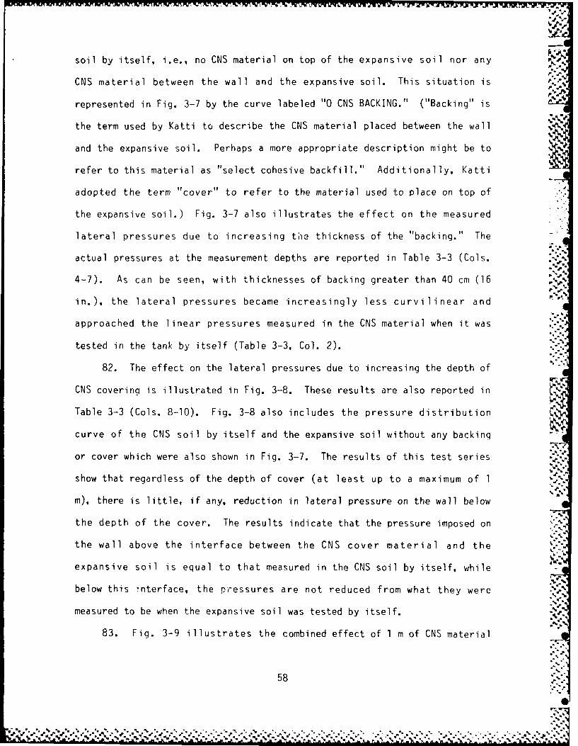
soil by itself, i.e., no CNS material on top of the expansive soil nor any
CNS material between the wall and the expansive soil. This situation is
represented in Fig. 3-7 by the curve labeled "0 CNS BACKING." ("Backing" is
the term used by Katti to describe the CNS material placed between the wall
and the expansive soil. Perhaps a more appropriate description might be to
refer to this material as "select cohesive backfill." Additionally, Katti
adopted the term "cover" to refer to the material used to place on top of
the expansive soil.) Fig. 3-7 also illustrates the effect on the measured
lateral pressures due to increasing the thickness of the "backing." The
actual pressures at the measurement depths are reported in Table 3-3 (Cols.
4-7). As can be seen, with thicknesses of backing greater than 40 cm (16
in.), the lateral pressures became increasingly less curvilinear and
approached the linear pressures measured in the CNS material when it was
tested in the tank by itself (Table 3-3, Col. 2).
82. The effect on the lateral pressures due to increasing the depth of -"
CNS covering is illustrated in Fig. 3-8. These results are also reported in
Table 3-3 (Cols. 8-10). Fig. 3-8 also includes the pressure distribution
curve of the CNS soil by itself and the expansive soil without any backing
or cover which were also shown in Fig. 3-7. The results of this test series
show that regardless of the depth of cover (at least up to a maximum of 1 -
m), there is little, if any, reduction in lateral pressure on the wall below
the depth of the cover. The results indicate that the pressure imposed on
the wall above the interface between the CNS cover material and the
expansive soil is equal to that measured in the CNS soil by itself, while
below this interface, the pressures are not reduced from what they were
measured to be when the expansive soil was tested by itself.
83. Fig. 3-9 illustrates the combined effect of 1 m of CNS material
58

LATERAL PRESSURE, KG/CM 2
o 0.50 1.00 [.50 2.00 2.50 3.000
100-
150-
250--0--0 CM CNS COVERING-D--CNS FULL DEPTH-.*-20 CM CNS COVERING--o-60 CM CNS COVERING
300 --- 100 CM CNS COVERING
350LFigure 3-8. Measured lateral pressures with depth for cohesive nonswellingsoil (CNS) only, swelling expansive soil only, and swelling expansive soil
with various thicknesses of CNS on top of the expansive soil (cover).(After Katti, et al., 1983)
59 5 ~
% %5

LATERAL PRESSURE, KG/CM 2
0 0.50 1.00 1.50 2.00 2.50 3.000 t
00%m~
50-
100-
150-.*
£200 *I
250- 1K
-<>-0 CM CNS COVERING-Q-CNS FULL DEPTH
--*--2O CM CNS BACKING 8 100 CM CNS COVER--- 60 CM ONS BACKING 8 100 CM CNS COVER-- x- 100 CM CNS BACKING 8 10O CM CNS COVER
350LFigure 3-9. Measured lateral pressures with depth for cohesive nonswellingsoil (CNS) only, swelling expansive soil only, and swelling expansive soilwith various thicknesses of CNS both as cover and between the wall and the
swelling expansive soil. (After Katti, et al., 1983)
60
,.~~~~~~~e le.*... **. ..-

cover with varying thicknesses of CNS select backfill. The measured
pressures at the various depths are reported in Table 3-3 (Cols. 11-13).
Fig. 3-9 illustrates that the combination of a 1 m thick CNS cover with an
increasing thickness of CNS select backfill has the effect of reducing the
lateral pressures acting on the wall. However, comparing the results of
this test series to those obtained in the first test series (expansive soil
with no CNS cover and increasing thicknesses of select backfill), it is p
obvious that the combination is not as successful in reducing the pressures
acting on the wall as using only increasing thicknesses of CNS select
backfill.
84. This same conclusion is illustrated in Fig. 3-10 which compares
the percentage of reduction in lateral pressure achieved by each of the
systems with an increasing thickness of select cohesive backfill. The N
effect of a CNS material cover in reducing the lateral pressure on the wall
is also shown in Fig. 3-10. This curve confirms what Fig. 3-8 illustrated,
i.e., essentially no reduction in lateral pressure on the wall below the
depth of the CNS cover regardless of the thickness of the cover. The data
used to develop Fig. 3-10 is reported in Table 3-4.
85. Despite its failure to reduce the lateral pressures exerted on the
wall by the swelling expansive soil, the cover was found to still have a .-
benefit. It was found that as the select cohesive nonswelling cover
material increased in depth, the heave measured at the surface of the test
soil decreased. As reported in Table 3-5 and illustrated in Fig. 3-11, the
thickness of the select backfill had no significant effect on the total
heave measured at the surface of the test soil. However, as the select CNS
cover material increased in depth, the measured surface heave decreased to
essentially zero with 1 m of cover thickness. This reduction of surface

100
.. ,
80-
Wb
~->S
W
C.5
< ol
BAKN100 0 M N OE
-6- COVER WITH ZEO.S AKN
20-z
0 V
m,. . ............ ",.,
0 20 40 60 80 100 120
THICKNESS OF CNS COVER OR BACKING, CM -;
-,-
Figure 3-10. P-]oticnship between the reduction in measured lateral -
pressures and thicknesses of cohesive nonswelling soil (CNS) either -.as cover or bac'kfill between the wall and the swelling expansive _.
soil. (After Katti, et al., 19833)''._
62 :::
W . ,% . , % ,, ,. , , . . .' .".% " . " . ." . '." ,% ."w,' ' ,' ' . .,.

Table 3-4.
Reduction in measured lateral pressures as a result of various thicknessesof cohesive nonswelling soil (CNS) between the wall and the swelling
expansive soil with and without CNS cover.(After Katti, et al., 1983)
Lateral Pressure, Kg/cm'
Expansive Exp. SoilDepth Soil With Backing CNS Soil Percent
Condition (cm) Only or Cover Only Reduction
20 cm CNSBacking 250 2.71 1.89 0.86 44.3w/o cover
40 cm CNSBacking 220 2.63 1.10 0.75 81.4w/o cover
60 cm CNSBacking 250 2.71 1.07 0.86 88.6w/o cover
100 cm CNSBacking 220 2.63 0.94 0.75 89.9w/o cover
20 cm CNSBacking with 250 2.71 2.00 0.90 39.2100 cm CNScover
20 cm CNSCover with 255 2.75 2.73 0.7backing
60 cm CNSCover with 220 2.63 2.79 --- -6.1backing
100 cm CNSCover with 250 2.71 2.64 --- 2.6backing
aExtrapolated from P= (depth - 3.47)/288.05s
.-

Table 3-5.
Measured heave resulting from various thicknesses of cohesive nonswellingsoil (CNS) used in various combinations of cover and backfill between the
wall and the swelling expansive soil. (After Katti, et al.. 1983)
Measurement Measured Heave (cm)
Depth Expansive CNS *
Condition (cm) Soil Soil Composite
20 cm CNS Backing 0 11.1 2.8w/o CNS cover 30 8.9 -
60 - 2.090 0.5 - -
150 0 -
40 cm CNS Backing 0 9.9 0.8w/o CNS cover 40 1.8 -
100 0.8 0.7160 0 0.8
60 cm CNS Backing 0 10.7 0.6w/o CNS cover 40 9.0 -
70 - 0.5 -_100 0 - - ,1130 - 0.5180 0 -
100 cm CNS Backing 0 10.3 0.2w/o CNS cover 40 9.0 1.0
70 2.6 - N
100 1.0 0 - ."
160 0 -
20 cm CNS Cover 0 - - 9.5w/o CNS backing 65 - - 4.0
125 - - 0
60 cm CNS Cover 0 - - 2.9w/o CNS backing 40 - - 2.0
70 - - 0.5100 - - 0.2160 - - 0
100 cm CNS Cover 0 - - 0.1w/o CNS backing 70 - - 0
130 - - 0.4190 - - 0
20 cm CNS Backing 0 - - 0.1w/ 100 cm CNS cover 70 - - 0.2
130 - - 0.8190 - - 0
60 cm CNS Backing 0 - - 0.1v/ 100 cm CNS cover 70 - - 0.2
130 - - 0.5190 - - 0
100 cm CNS Backing 0 - - 0.1w/ 100 cm CNS cover 70 - - 0.2
100 - - 0.1130 - - 0.4190 - - 0
64
' % ,% % , %- % % .% %. % •% % ... .. .. . . , P
-%2', ,,-,,' ,,'',;,:aa,.. .,,,., -. ,,,,,.,.. .. , ,,. '-, .',.. , ...-.-. ,.:.- ,., - . _-- .%,

-.1" M aJXIA P17 "-a. FY -d F- ." -.
12-
10-
8- --- BACKING W/O COVER--o-COVER W/O~ BACKING--&-BACKING W/ 100 CM COVER
Li
>w6<
0
W
2--
L .........
0O 20 40 60 80 100 120
THICKNESS OF CNS BACKING OR COVER, CM -
Figure 3-11. Measured surface heave resulting from various thicknesses
of cohesive nonswelling cover soii (CNS) with and without any UrSbackfill betw;een the wall and the swelling expansive soil.
(After Katti, et al., 1983)
65
LV

.-
heave to essentially zero was shown to also hold when the thickness of the
cover material was held at a constant thickness of 1-m while the select
backfill thickness increased from 20 cm (8 in.) to 1-m (39 in.). Thus, the
CNS cover was beneficial in reducing the amount of surface heave but has no
apparent benefit in reducing the magnitude of the lateral swelling pressures
imposed on the wall by the swelling expansive soil.
86. Finally, the coefficients of at rest earth pressure and passive
earth pressure were calculated for several depths for the various
combinations of cover thickness and select backfill thickness. These
results are shown in Table 3-6, and some of the values of K are compared0
with depth and thickness of select backfill in Fig. 3-12. These comparisons
show the at-rest earth pressure coefficient decreased significantly with
just 20 cm (8 in.) of select backfill between the wall and the swelling
expansive soil. A lesser and nearly linear decrease in the value of K --but0
still a significant decrease--occurred until the thickness of the select
backfill reached 60 cm (24 in.). With no CNS cover, K increased slightly
(approximately 12 to 14 percent) as the thickness of the select backfill
increased from 60 to 100 cm (24 to 39 in.). However, with 1-m of select
cover thickness, K continued to decrease as the thickness of the select0
backfill increased from 60 to 100 cm, but the K values of the soil covered 4-.0
with 1 m of select CNS material all were significantly greater than those
with the same thickness of select backfill but without CNS cover. Thus, -
with respect to reducing the at-rest earth pressure coefficient, the CNS
material was not as successful when used as either a covering only or in
combination with the select backfill.
87. Some observations are reported regarding the K values obtained0
from the various test series. K values calculated for air-dry loose sand0
66-.
0,

E d l-i
0 r
he_ - I% I I J
(AA
0 0-~ a. C%
a~i' C)o
S-- 00 a-
-P III .4.- *. -it .1 V)*.0 4- C% 0E 0
0 >i Idu u C~jC%J
(A ~ E0a
0 Nd I I I v IS oS 0 E. Mc'J
-e) 4 -0
)iI I
0 % 10 Ch0 0C'.
4- (D I e
4-C7n d) I I I I0 wU
411
C cl
4-3 C/) 0 c
-o v) *.- d
Q. rdC .
(D 0 0
00 a) ~' e -w
4-3 C)
r. CLCD %0 be- I I - I
LI) CV)67
>.
I.E a i C.a ~ant. ~ a r.C.

w~ C)
0) C0U
.- LO
9. \j C"J %
1)
0 0. C0
S-S
L) 0)
C) 0 __ __ __ __00__
L)O
00
a l m9 9i *l %.
k 0 1
D0) 0 00 ODCO r-o Ne I I I . 4
F- .CY
C-)C- 0 0
0.N C\J
u CL CO
0
4-)) C/) *n *)0, 0 OC C) O C~o U\ N-4) V- - CO tt
U6
1.. 0%

14
I S
120
- 85 CM DEPTH, NO CNS COVERm tO-a-a 145 CM DEPTH, NO CNS COVER
WpA 130 CM DEPTH, 100 CM COVER0.- - - - CNS BACKFILL ONLY
18-
W V-
C'.
I - ":..
04 -
zW
U_
0
C.) :,--A
0 20 40 60 80 100
THICKNESS OF SELECT BACKFILL, CM
Figure 3-12. Reduction of the calculated coefficient of at-rest earthpressure, K , at selected depths with various thicknesses of cohesivenonswelling soil (CNS) between the wall and the swelling expansive
soil with and without CNS cover. (After Katti, et al., 1983)
69

and air dry loose CNS material were 0.63 and 0.46, respectively. In
comparison, the K values calculated by Jaky's equation (1948) were 0.63 and0
0.48, respectively. However, the K values calculated in the experiment for
the compacted samples of each of the soils were well in excess of 1.0, much l
greater than that estimated from the Jaky equation.
88. The K values for the compacted sand prior to saturation wereo
somewhat smaller than the values after saturation. It was also noted that
the change in K with depth was linear. Similar results were observed for
the cohesive nonswelling soil, i.e., a slight increase in K following
saturation and a linear increase in the magnitude of Ko with depth.
However, this was not the observation with respect to the expansive soil.
Prior to saturation, K was found to increase linearly with depth as was the0
case with the other two soils. But when permitted to imbibe water, the
value of K increased rapidly and nonlinearly with depth as was illustrated0
in Fig. 3-7. However, after a depth of approximately 150 cm (60 in.), the
rate of increase in K begins to decrease as the overburden pressure becomes0
greater.
89. It was also noted in the report that the peak value of lateral
pressure takes place at percentages of saturation less than 100 percent.
Each of the compacted expansive soil test samples was permitted to imbibe
water for a period of 70 days to ensure saturation conditions. In each
instance, the maximum heave was observed to occur at approximately 30 to 40 ..
days following the introduction of free water to the sample. The peak heave
was followed by a small reduction which then remained essentially constant
for the remainder of the imbibition period.
90. F rini 1y, Katti, Pt al., introduced an equation that permits the
u',er to Pt -a te a dn, i qn lateral pressure:
70 i
7() " "a.
# " W ' °. -. -. " ." ." -" % . ".. "-. . . . .. -. . .". " . . " -° -. . -, . - "."w '... •..' .-- " ... , -" " W" .T
g.

PL = PCNS + (O• 2 )(qsw - PCNS ) (3-40)
where
PL = design lateral pressure, kg/cm2
PCNS = lateral pressure of CNS material for the corresponding
depth, kg/cm2
qsw = swelling pressure of oven-dry expansive soil at no volume
change condition, kg/cm2
91. Thus, this very extensive laboratory testing program has shown
that inserting another cohesive soil material of a specified minimum thick-
ness between the expansive soil and the wall can effectively reduce the
lateral pressure transmitted to the wall from the swelling expansive soil.
The testing program showed that the thickness of this cohesive soil material
should be at least 40 cm (16 in.) to begin to reduce the transmitted
pressure and most probably the minimum thickness should be approximately
1 m. Fig. 3-10 shows that approximately 90 percent of the maximum expected
swelling pressure in the expansive soil can be prevented from reaching the
wall with a 1 m thick layer of select cohesive nonswelling backfill
material. Additionally, the experimental program showed that placing a
covering comprised of cohesive nonswelling material over the expansive soil
will not reduce the lateral pressures transmitted to the wall from the
swelling expansive soil, but the CNS cover material will reduce the vertical
heave of the surface. A cover thickness of 1 m was found to eliminate
effectively all surface heave. The magnitude of the coefficient of at-rest
earth pressure was also shown to be reduced significantly until at least
approximately 60 cm (24 in. ) of select cohesive nonswelling backfill
material had been placed between the wall and the swelling expansive soil.
With greater thickness, K was found to remain essentially constant ora+;,
71 ;'p.
, , - :j.,-,-,..,.,;: - ,-..,,...- -.- ,-. .- ,_. y,-. . ...-.-. ,. ,.- ,......-..<;-; - ... , .-... ; -e!T

perhaps to increase slightly in magnitude. Finally, an equation for
predicting design lateral earth pressure was presented which required
knowing the lateral earth pressure in the CNS material at a particular depth
and the swelling pressure of oven-dry expansive soil at no volume change
conditions, which could presumably be determined from oedometer testing.
I..,
~-
*'.%
A%
:a..
L, A 72 "'-
' W',',, 4' ' ',[ _W_, ,". .,.
' '_._., .-. ' 4" . .' ," " .'," " . , , ',W.. .'." ' . . ."." '." w ." .' '. .. ,, •

IML Am
PART IV: CONCLUSIONS
92. This study was limited to a search of the technical literature.
Nonetheless, some conclusions can be drawn from this effort.
93. Although not exhaustive, the search of the technical literature
being reported here is as complete as time and budgetary limitations permit-
ted. There are numerous publications on topics that are supplementary,
peripheral, or supportive of this study topic of lateral earth pressures
resulting from swelling expansive soil. A large number of these publica-
tions were reviewed but not included in the bibliography that accompanies
this report because they were considered not to be either primarily or
secondarily contributing to the specific problem being studied. Addition-
ally, there are some papers published in foreign regional conference
proceedings that from their titles appear to discuss some aspect directly
related to the study topic, but, they could not be obtained for one or more
of a number of reasons. Thus, despite these enumerated limitations, this
study most likely comprises the most complete literature search of this
particular topic to date and will provide an excellent departure point for
further study of this problem.
94. There are many publications that report on studies made of the
swelling pressures developed by swelling expansive soils. However, it was
found that many of these results did not have any direct relationship or
application to the problem being studied. Often, the experiment produced
results obtained from compacted expansive soils under conditions that simply
did not conform to what is typically encountered in the field.
Consequently, although these papers and reports were duly read and
considered, they were not included in the discussion presented in Part II. %
95. From the literature search conducted in this study, three methods
73 "" ""
'- %.

or procedures appear to possess potential for predicting the lateral
pressures that might be expected to occur in the field when structures with
rigid basement walls are constructed in expansive soils.
a. Skempton's Method. Skempton introduced a method whereby thecoefficient of at rest earth pressure and the effectivehorizontal pressure might be calculated using data obtainedfrom a field investigation and a subsequent laboratorytesting program. Soil properties required to apply thismethod include the effective vertical stress, the in situ *
capillary pressure or soil suction, and the pore pressureparameter, A . Using these soil properties for each point .%
below the surface to be investigated, the at rest coefficientof earth pressure and the effective horizontal earth pressurecan be calculated.
b. Fredlund's Method. Using some simplifying assumptions,Fredlund applied limit analysis theory to the problem oflateral earth pressures in unsaturated soils. Althoughapplication of the equations developed from limit analysis issomewhat limited because of the simplifying assumptions, theynonetheless provide an analytical solution to a very complex ,problem. As with Skempton's method, the soil propertiesneeded to apply these equations are routinely available fromtypically conducted site investigations and laboratory tests:unit weights of the soil for both saturated and unsaturatedconditions, the effective angles of internal frictionrepresenting both saturated and unsaturated conditions, theeffective value of the soil cohesion, the matrix soilsuction, and the depth to the groundwater table. However,the Fredlund equations are only applicable to the active andpassive failure conditions and do not address at restconditions. Thus, to use these equations to attempt topredict the design lateral pressures expected to betransmitted to a basement wall, the passive conditionequation must be used to estimate an upper limit to theexpected lateral pressure, which is a shortcoming inattempting to use this method in design applications.
c. Katti's Method or the Select CNS Backfill Method. The N,results of an extensive laboratory investiga-tion showed thatplacing a minimum thickness of a select cohesive nonswellingsoil (CNS) between the basement wall and the swellingexpansive soil effectively reduced the swelling pressurestransmitted to the wall. The results obtained from the testprogram for the two soils used in the investigation showedthat at least 40 cm of the select backfill are required torealize any significant reduction in the lateral pressuresand that 100 cm are necessary to reduce the lateral pressures edeveloped in the restrained expansive soil by 90 percent.,.'Additionally, the tests showed that as the thickness of theselect backfill increased, the pressures transmitted to theN
74
W,

wall began to approach those transmitted to the wall by theselect backfill soil by itself in K conditions. Otherresults from the study showed that covering the expansivesoil with as much as 100 cm of the select backfill soilproduced little reduction in the lateral pressurestransmitted to the wall. Therefore, these results suggestthat the lateral pressures expected to be exerted against abasement wall constructed in expansive soil may be mitigatedby placing a suitable thickness of nonswelling cohesive soilbetween the wall and the naturally occurring expansive soilof the construction site. Extending the results of thistest, it is likely that if the select backfill is thick Z-Ienough, the lateral pressures generated by the swellingexpansive soil could be sufficiently diminished so that thewall design could be accomplished based upon K conditions ofthe select backfill soil. o
96. Based on the results reported by both Ahmed and Katti, et al., it
appears that the geometry of the thickness of the backfill placed against "
the wall has an effect on the magnitude of the lateral pressure transmitted
to the wall. However, the results reported by both investigators imply that
there is a minimum thickness for a particular wall height, whereby the
transmitted pressure is reduced to a minimum. Further increase in backfill
thickness beyond this minimum value does not result in any significant
further decrease in horizontal pressure on the wall.
97. The three methods presented above have consider-able potential
for application to practical problems. However, none have apparently
actually been applied to a field problem, or at least applied to a field
problem where measurements were taken to assess the validity of the
pressures predicted by any of the methods. Therefore, if any of these
methods should be used to attempt to estimate lateral pressures for design
of a nonyielding basement wall, appropriate caution should be applied in
using any of the results obtained.
75
% *% a

PART V: RECOMMENDATIONS
98. Because this study was limited to a search of the technical%
literature and no laboratory or field testing was accomplished to validate%
the conclusions presented in Part IV, it is recommended that an experiment
be devised and conducted that will provide field measurements that can be
used to compare the predicted lateral pressures to the lateral pressures
actually occurring under field conditions. It is believed that only through
such comparative means can the three methods or procedures that appear to
have potential be evaluated and either verified, modified, or rejected.
76-

vl W. TV W
REFERENCES
Abdelhamid, M. S.. and Krizek, R. J., 1976, "At-Rest Lateral Earth Pressureof a Consolidating Clay," Journal of the Geotechnical Div., ASCE, Vol. 102,No. GT7, July, pp. 721-738.
Agarwal, K. P., and Sharma, S. C., 1973, "A Method for Measuring SwellingPressure of an Expansive Soil," Proceedings, 3rd Int'l Conference onExpansive Soils, Haifa, Israel, Vol. 1, pp. 155-159.
Ahmed, H. I., 1967, "Theoretical and Experimental Analysis of the Bin Effect ,on Lateral Earth Pressure," Thesis presented in partial fulfillment of therequirements for the degree of Master of Science in Civil Engineering,University of Washington, Seattle, WA.
Aitchison, G. D., and Richards, B. G., 1969, "The Fundamental MechanismsInvolved in Heave and Soil Moisture Movement and the Engineering Propertiesof Soils Which are Important in Such Movement," Proceedings, 2nd Int'lConference on Expansive Clay Soil," Texas A&M Univ., College Station, TX,pp. 66-84. %
Allam, M. M., and Sridharan, A., 1984, Discussion, "A Simple Question AboutConsolidation," Journal of the Geotechnical Div., ASCE, Vol. 110, No. GT5,May, pp 671-672.
Alpan 1., 1957, "An Apparatus for Measuring the Swelling Pressure inExpansive Soils," Proceedings, 4th Int'l Conference on Soil Mechanics andFoundation Engineering, Vol. I. London, pp. 3-5.
Barber, E. S., 1956, Discussion, "Engineering Properties of ExpansiveClays," ASCE, Transactions, Vol. 121, pp. 669-673.
Bhangale. E. S., Katti, R. K., and Moza, K. K., 1983, "Effect of CNS LayerBacking on Lateral Pressure of Expansive Soil," Proceedings, 7th AsianRegional Conference on Soil Mechanics and Foundation Engineering.
Bjerrum, L., and Anderson, K. H., 1972, "In-Situ Measurement of LateralPressures in Clay," Proceedings, 5th European Conference on Soil Mechanics ..".and Foundation Engineering, Vol. 1, Madrid, pp. 11-20.
Blight, G. E., 1967, "Horizontal Stresses in Stiff and Fissured LacustrineClays," Proceedings, 4th Regional Conference for Africa on Soil Mechanicsand Foundation Engineering, Cape Town, South Africa, December, pp. 95-99.
Bolt, G. H., 1956, "Physico-Chemical Analysis of the Compressibility of PureClays," Geotechnique, Vol. 6, pp. 86-93.
Bowles, J. E., 1982, "Foundation Analysis and Design, 3rd Ed., McGraw-Hill ,dBook Co., New York, NY. "..
Brackley, I. J. A., 1973, "Swell Pressure and Free Swell in a CompactedClay," 3rd Int'l Conference on Expansive Soils, Vol. 1, Haifa, Israel, pp.169-176.
77
A. N

Brackley, I. J. A., 1975, "Swell Under Load," Proceedings, 6th RegionalConference for Africa on Soil Mechanics and Foundation Engineering, Vol. I, *.A
Durban, pp. 65-70.
Brooker, E. W., and Ireland, H. 0., 1965, "Earth Pressures At Rest Relatedto Stress History," Canadian Geotechnical Journal, Vol. 2, No. 1, February,pp. 1-15.
Brooker, E. W., 1967, "Strain Energy and Behavior of OverconsolidatedSoils," Canadian Geotechnical Journal, Vol. 4, No. 3, September, pp. 326-333.
Bucher, F., and Sailie, E. L., 1984, Swelling Behavior of Tropical BlackClays," Proceedings, 8th Regional Conference for Africa on Soil Mechanicsand Foundation Engineering, Harare, pp. 81-86.
Chen, F. H., 1975, Foundations on Expansive Soils, Elsevier ScientificPublishing Co., New York, NY.
Coulomb, C. A., 1776, "Essai sur une application des regles de maximis etminimis a quelques problemes de statique ralatifs a l'architecture,"Memoires de la mathematique et de physique, Paris, De L'Imprimerie Royale,pp. 343-382. (Presentes a l'Academie Royale des Sciences, par diverssavans, et lus dan ses Assemblees, Vol. 7, Annee 1773.)
Culmann, K., 1866, "Die Graphische Statik," (Section 8, Theorie Der Stutzand Futtermauern), Zurich, Meyer und Zeller.
Dakshanamurthy, V., 1978, "A New Method to Predict Swelling Using aHyperbolic Equation," Indian Geotechnical Journal, Vol. 9, pp. 29-38.
Didier, G., 1973, "Swelling Pressures of Soils--Experimental Device--Fieldof Utilization," Proceedings, 3rd Int'l Conference of Expansive Soils, Vol.1, Haifa, israel, pp. 187-193.
El Sohby, M. A., and Rabbaa, S. A., 1984, "Deformational Behaviour ofUnsaturated Soils Upon Wetting," Proceedings, 8th Regional Conference forAfrica on Soil Mechanics and Foundation Engineering, Harare, pp. 129-137.
Finn, W. D., and Strom, B., 1958, "Nature and Magnitude of Swell Pressure," i"%Proceedings, Highway Research Board, Vol. 37, Washington, DC, pp. 493-505.
Fredlund, D. G., Morganstern, N. R., and Widger, R. A., 1978, "The ShearStrength of Unsaturated Soils," Canadian Geotechnical Journal, Vol. 15, pp.313-321.
Fredlund, D. G., 1979, "Second Canadian Geotechnical Colloquium:Appropriate Concepts and Technology for Unsaturated Soils," CanadianGeotechnical Journal, Vol. 16, pp. 121-139.
Fredlund, D. G., 1987, "Soil Mechanics Principles for Highway Engineering inArid Regions," Preprint of Paper Presented at the Annual Mleeting of theTransportation Research Board, Washington, DC, January, 38 pp.
78
op, ~ ve r % , '0, 0 "

-1
Gokhale, K. V. G. K., and Jain, K. K., 1972, "Anisotropic Swelling in BlackCotton Soil," Bulletin of the International Association of EngineeringGeology, Paris, No. 5, pp. 63-72.
Gould, J. P., 1970, "Lateral Pressures on Rigid Permanent Structures,"Lateral Stresses in the Ground and Design of Earth-Retaining Structures,State-of-the-Art Papers Presented at the Specialty Conference, SoilMechanics and Foundation Engineering Div., ASCE, Cornell Univ., Ithica, NY,pp. 219-269.
Grim, R. E., 1958, "Water and Its Conduction in Soils: Organization ofI-later on Clay Mineral Surfaces and Its Implications for the Properties ofClay-Water Systems," Hiqhway Research Board Special Report No. 40,Washington, DC, pp. 17-23.
Grim, R. E., 1959, "Physico-Chemical Properties of Soils: Clay Minerals,"Journal of the Soil Mechanics and Foundation Engineering Div., ASCE, Vol.85, No. SM2, April, pp. 1-17.
Hannon, J. B., and Jackura, K. A., 1985, "Measurement of Earth Pressure,"Transportation Research Record 1004, Washington, DC, pp. 6-13.
Harris, G. M., 1984, "Earth Pressure Measurements Behind a 20 Metre HighRetaining Wall," Proceedings, 8th Regional Conference for Africa on SoilMechanics and Foundation Engineerinq, Harare, pp. 443-452.
Ho, K. Y. F., and Fredlund, D. G., 1982, "Increase in Strength Due toSuction for Two Hong Kong Soils," Proceedings, Conference on Engineering andConstrt,'tion in Tropical and Residual Soils, ASCE, Honolulu, pp. 263-295.
Holtz, R. D., and Jamiolkowski, M. B., 1985, Discussion, "Time Dependence of iLateral Earth Pressure," Journal of the Geotechnical Div., ASCE, Vol. III,No. GTIO, October, pp. 1239-1241.
Holtz, W. G., and Gibbs, H. J., 1956, "Engineering Properties of ExpansiveClays," Transactions, ASCE, Vol. ]21, pp. 641-677.
Jaky, J., 1948, "Pressure in Silos," Proceedings, 2nd Int'l Conference onSoil Mechanics and Foundation Engineering, Vol. 1, Rotterdam, pp. 103-107.
Joshi, R. P., and Katti, R. K., 1980, "Lateral Pressure Development Under 4Surcharges," Proceedings, 4th Int'l Conference on Expansive Soils, Vol. 1,Denver, CO, pp. 227-241. .'
Kallstenius, T., and Bergau, W., 1961, "In Situ Determination of HorizontalGround Movements," Proceedings, 5th Int'l Conference on Soil Mechanics andFoundation Engineering, Paris, Vol. 1, pp. 481-485.
Kassiff, G., and Shalom, A. B., 1971, "Experimental Relationship 6etweenSwell Pressure and Suction," Geotechnique, Vol. 21, No. 3, pp. 245-255.
Kassiff, G., Baker, R., and Ovadia, Y., 1973, "Swell-Pressure Relationshipsat Constant Suction Changes," Proceeding', 3rd Int'l Conference on ExpansiveSoils," Vol. 1, pp. 201-208. •
79

.%-..
Katti, R. K., and Kate, J. il., 1975, "Role of Micro Particles in interactionBetween CNS Layer and Underlying Expansive Soil Media," Proceedings, 5thAsian Regional Conference on Soil Mechanics and Foundation Engineering, Vol.1, Bangalore, India, pp. 15-18.
Katti, R. K., et al., 1980, "Shear Strength Development in Expansive BlackCotton Soil V.*edia WIith and W. ithout a Cohesive Njon-Swelling Soil Surcharge %and Application to Stability of Canals in Cuts and Embankments," TechnicalReport No. 28, 'ientral Board of Irriqation and Power, [fle, Delhi, 142 pp.
Katti, R. K., Bhangale, E. S., and tioza, K. K., 1983, "Lateral Pressure inExpansive Soil I.'ith and W1ithout a Cohesive Non-Swelling Soil Layer-Application tc Earth Pressures on Cross Drainage Structures in Canals andKey Walls in Dams," Part I (Studies on K Condition), Technical Re[ rt N o.32, Central Board of Irriqation and Power, °'e, Delhi, India, 102 pp.
Katzir, ., N nd David, D. , 1969, "Foundations in Expansive Marl ,"Proceedinos, 2nd Int'l Conference on Expansive Clay Soils, Texas A&0 Univ.,College Station, TX, pp. 374-377.
Kavazanjian, E., Jr., and Mitchell, J. K., 1984, "Time Dependence of LateralEarth Pressure," Journal of the Geotechnical Div., ASCE, Vol. 1 10, N.Jo. 4,April, pp. 530--33.
Kavazanjian, F., Jr., and M.itchell, J. K., 1985, Discussion Closure, "TimeDependence of Lateral Eart.h Pressure," Journal of the Geotechnical Div.,ASCE, Vol. 111, [jo. GT O, October, pp. 1246-1248.
Komornik, A., Livren, .. , 1968, "The Effect of Anisotropy on Swelling of aCompacted Clay," Proceedinas, 3rd Asian Regional Conference on SoilMechrkric:s and Foundition Engineering, Vol. II, pp. 181-185.
Komornik, A., 1969, "Factors Affecting Damage Due to Movements of ExpansiveClays in the Field," Proceedings, 2nd Int'l Conference on Expansive ClaySoils," Texas A&[,I Univ., College Station, TX, pp. 37-65.
Komornik, A., and David, D., 1969, "Prediction of Swelling Pressure ofClays," Journal of the Sil Mechanics and Foundation Engineering Div., ASCE,Vol. 95, No. . -1, January, pp. 209-225.
Komornik, A., Wiseman, G. , and Ben-Yaacob, Y. , 1969, "Studies of In SituMoisture and Swelling Potential Profiles," Proceedings, 2nd Int'l Conferenceon Expansive Clay Sois," Texas A&M Univ., College Station, TX, pp. 348-361.
Komornik, A., and leitlen, i970, "Laboratory Determination of Lateral andVertical Stresse, in Compacted ',welling Clay," Journal of Mlaterials, JMLSA,Vol. 5, Na. 7, i41crch, pp. 108-123.
Lacerda, '. A., and tartins, S. N., 1985, Discuss ion, "Time Dependence ofFa''r~1 Farth Pretsijre, " Journal of the Geotechnical Div., ASCE, Vol. I11 ,
' Tl0, O bO r, op. 12,12-1244.
f1960, 'l' chan i srs of Swel li no by Compacted Clay,'' hway, i f:l, in 245, lahinqton, DC, pp. 10-26.
80• . . .... .... .. "%0

Ladd, C. C., 1965, "Stress-Strain Behavior of Anisotropically ConsolidatedClays During Undrained Shear," Proceedings, 6th Int'l Conference on SoilMechanics and Foundation Engineering, Vol. I, Montreal, pp. 282-286.
Laier, J. E., and Lamar, J. H., 1980, "Minimizing Foundation Swell Potentialin Yazoo Clay," Proceedings, 4th Int'l Conference on Expansive Soils," 6-
Denver, CO, pp. 421-437. _
Lambe, T. W., 1958a, "Compacted Clay: Structure," Transactions, ASCE, Vol.125, May, pp. 682-717.
Lambe, T. W., 1958b, "Compacted Clay: Engineering Behavior," Transactions,ASCE, Vol. 125, May, pp. 718-756.
Leonards, G. A., 1985, Discussion, "Time Dependence of Lateral EarthPressure," Journal of the Geotechnical Div., ASCE, Vol. 111, No. GTIO,October, pp. 1244-1246.
Livneh, M., Kassiff, G., and Wiseman, G., 1969, "The Use of Index Proper-ties in the Design of Pavements on Expansive Clays," Proceedings, 2nd Int'lConference on Expansive Clay Soils," Texas A&M Univ., College Station, TX,pp. 218-234.
Low, P. F., 1959, Discussion, "Physico-Chemical Properties of Soils: IonExchange Phenomena," Journal of the Soil Mechanics and Foundation Engineer-ing Div., ASCE, Vol. 85, No. S12, April, pp. 79-89. -.-
McRoberts, E., 1984, Discussion, "A Simple Question About Consolidation,Journal of the Geotechnical Div., ASCE, Vol. 110, No. GT5, May, pp. 667-669.
Massarsch, K. R., 1975, "New Method for Measurerent of Lateral EarthPressure in Cohesive Soils," Canadian Geotechnical Journal, Vol. 12, No. 2,pp. 142-146.
Massarsch, K. R., et al., 1975, "Measurement of Horizontal In-SituStresses," Proceedings, The Specialty Conference on In-Situ Measurement ofSoil Properties, ASCE, Raleigh, NC, pp. 266-286.
Menzies, B. K., Sutton, H., and Davies, R. E., 1977, "A New System forAutomatically Simulating K Consolidation and K Swelling in Conventional
0 0Triaxial Cell," Geotechnique, Vol. 27, NIo. 4, pp. 593-596.
Meschyan, S. R., and Malakyan, R. P., 1975, "Earth Pressures From ClaySoils," Translated from Osnovaniya, Fundamenty i iekhanika Gruntov, No. 5,Sep-Oct, 1974, pp. 42-43.
Michaels, A. S., 1959, Discussion, "Physico-Chemical Properties of Soils:Soil-Waier Systems," Journal of the Soil Mechanics and FoundationEngineerinDiv., ASCE, Vol. 85, No. SM2, April, pp. 91-102.
Mitchell, J. K., 1956, "The Importance of Structure to the EngineeringBehavior of Clay," Thesis presented in partial fulfillment of the 1k
requirements for the degree of Doctor of Science, MIT, Cambridge, MA.
81
% %,

Nagaraj, T. S., 1984, Discuss ion, "A Simple Question About Consolidation,"Journal of the Geotechni-al Div., ASCE, Vol. 110, No. GT5, May, pp. 665-667.
Nayak, N. V., and Christensen, R. W., 1971, "Swelling Characteristics ofCompacted, Expansive Soils," Clays and Clay irerals, Vol. 19, pp. 251-261.
Nichols, T. C., Jr., and Davidson, R. R., 1986, "In Situ and Laboratory Geo-technical Tests of the Pierre Shale Near Hayes, South Dakota--ACharacterization of Engineering Behavior," Canadian Geotechnical Journal,Vol. 23, pp. 181-194.
Nojiri, A., Kondo, S., and Hanamura, M., 1971, "Investigation of LateralEarth Pressure on Vertical Earth Supports," Proceedings, Southeast AsianGeotechnical Conference, Vol. 1, Bangkok, Thailand, pp. 441-444. .-
Novais-Ferreira, H., 1973, "The Influence of Compaction Moisture Content onOedometric Deformation and Swelling Pressure," Proceedings, 3rd Int'lConference on Expansive Soils, Vol. 1, Haifa, Israel, pp. 209-216.
Ofer, Z., 1982, "Lateral Pressure Developed During Compaction," Transporta- .tion Research Board Record 897, Washington, DC, pp. 71-79.
Ofer, Z., and Blight, G. E., 1985, "Measurement of Swelling Pressure in theLaboratory and In Situ," Transportation Research Board Record 1032, ',.Washington, DC, pp. 15-22.
Pacey, J. G., Jr., 1956, "The Structure of Compacted Soils," Thesispresented in partial fulfillment of the requirements for the degree ofMaster of Science, MIT, Cambridge, MA.
Parcher, J. V., and Liu, P. C., 1965, "Some Swelling Characteristics ofCompacted Clays," Journal of the Soil Mechanics and Foundation EngineeringDiv., ASCE, Vol. 91, No. SM3, May, pp. 1-17.
Parcher, I. V., and Liu, P. C., 1966, Discussion Closure, "Some wellingCharacteristics of Compacted Clays," Journal of the Soil Mechmnics andFoundation Engineering Div., ASCE, Vol. 92, No. SM4, July, pp. 73-74.
Pile, K. C., 1981, "The Relationship Between Matrix and Solute Suction,Swelling Pressure, and Magnitude of Swelling in Reactive Clays," Pro-ceedings, 3rd Australian-New Zealand Geomechanics Conference, pp. 197-202.
Poncelot, J. V., 1840, "Memoire sur la stabilite des revetments et de leursfondation," Note additionelle sur les relations analytiques qui lient entreelles la poussee et la butee de la terre, Memorial de 1 'officier du genie,Paris, Vol. 13.
Poulos, H. G., and Davis, E. H., 1972, "Laboratory Determination of In SituHorizontal Stress in Soil Iasses," Geotechnigue, Vol. 22, No. 1, pp. 177-182.
Pufahl, D. E., Fredlund, D. G., and Rahardjo, H., 1983, "Lateral EarthPressures in Expansive Clay Soils," Canadian Geotechnical Journal, Vol. 20,No. 2, pp. 228-241.
82
V ,.
% * *
, P -kA-.-. A . •~ ,r a P I

wX
Rahardjo, H., 1982, "Lateral Earth Force Calculations Using Limit .Equilibrium," Thesis presented in partial fulfillment of the requirementsfor the degree of Master of Science, University of Saskatchewan, Saskatoon,Sask.
Rahardjo, H., and Fredlund, D. G., 1983, "Lateral Earth Force Theory Using A.Limit Equilibrium," Report No. RP-31, Transportation and Geotechnical Group,Dept. of Civil Engineering, Univ. of Saskatchewan, Saskatoon, Sask., 36 pp.
Rahardjo, H., and Fredlund, D. G., 1984, "General Limit Equilibrium Methodfor Lateral Earth Force," Canadian Geotechnical Journal, Vol. 21, No. 1, pp.166-175.
Ranganatham, B. V., and Satyanarayana, B., 1965, "A Rational Method ofPredicting Swelling Potential for Compacted Expansive Clays," Proceedings,6th Int'l Conference on Soil Mechanics and Foundation Engineering, Vol. I.Montreal, pp. 92-96.
Ranganatham, B. V., and Satyanarayana, B., 1967, "Earth Pressures inExpansive Backfills," Proceedings, 3rd Asian Regional Conference on SoilMechanics and Foundation Engineering, Bangkok, pp. 116-119.
Ranganatham, B. V., and Pandian, N. S., 1975, "An Apparatus to RecordLateral Earth Pressure Under At Rest Conditions," Indian GeotechnicalJournal, Vol. 5, No. 3, July, pp. 186-192.
Rankine, W. J. M., 1857, "On the Stability of Loose Earth," PhilosophicalTransactions, Royal Society, London, Vol. 147.
Richards, B. G., 1977, "Pressures on a Retaining Wall by an Expansive Clay,"Proceedings, 9th Int'l Conference on Soil Mechanics and FoundationEngineering, Vol. 1, Tokyo, pp. 705-710.
Robertson, A. M. G., 1975a, "Lateral Swelling Pressures in Active Clay,"Proceedings, 6th Regional Conference for Africa on Soil Mechanics andFoundation Engineering, Vol. 1, Durban, pp. 107-114.
Robertson, A. M. G., 1975b, "Design Criteria for Lateral Pressures inExpansive Clays," Proceedings, 6th Regional Conference for Africa on SoilMechanics and Foundation Engineering, Vol. 2, Durban, pp. 169-174.
Rosenqvist, I. Th., 1959, "Physico-Chemical Properties of Soils: Soil-HaterSystems," Journal of the Soil Mechanics and Foundation Engineering Div.,ASCE, Vol. 85, No. SM2, April, pp. 31-53.
Rowe, P., 1957, "C = 0 Hypothesis for Normally Consolidated Clays at Equi-librium," Proceedings, 4th Int'l Conference on Soil Mechanics and FoundationEnginee; -q, Vol. I, London, pp. 189-192.
Saito, T.. and Yanai, K., 1969, "Some Swelling Characteristics of Compacted %Soils," Tryinsactions, Japanese Society of Civil Engineers, Vol. 1, Part 2,pp. 397-404.
83 1~
%'.W' .,'.' '-'• °. '.•
".°. -'.'..'.'•.'.',."." .".. .-.- ...- .- ., ,-" '...........................-............-..-....-...............-..,,.'•' '

Satyanarayana, B., lQ69, "Behaviour of Expansive Soil Treated or CushionedWith Sand," Proceedings, 2nd Int'l Conference on Expansive Clay Soils, TexasA&M Univ., College Station, TX, pp. 308-316.
Satyanarayana, B., 1973, "Effect of Anisotropy on Expansion Characteris-tics," Proceedings, 3rd Int'l Conference on Expansive Soils, Vol. 1, Haifa,Israel, pp. 217-225.
Schmertmann, J. H., 1983, "A Simple Question About Consolidation," Journalof the Geotechnical Division, ASCE, Vol. 109, No. GTI, January, pp. 119-122.
Schmertmann, J. H., 1984, Discussion Closure, "A Simple Question About Con-solidation," Journal of the Geotechnical Division, ASCE, Vol. 110, No. GT2,May, p. 673.
Seed, H. B., and Chan, C. K., 1959, "Structure and Strength Characteris-tics," Compacted Clays: A Symposium, Transactions, ASCE, Proceedings PaperNo. 2216, October, pp. 1343-1407. L_.
Seed, H. B., and Chan, C. K., 1961, "Compacted Clays--Structure and StrengthCharacteristics," Transactions, ASCE, Vol. 126, pp. 1343-1425.
Seed, H. B., Mitchell, J. K., and Chan, C. K., 1962, "Studies of Swell andSwell Pressure Characteristics of Compacted Clays," Highway Research BoardBulletin 313, Washington, DC, pp. 12-39.
Seed, H. B., Woodward, R. J., and Lundgren, R., 1962, "Prediction of Swell-ing Potential for Compacted Clays," Journal of the Soil Mechanics andFoundation Engineering Division, ASCE, Vol. 88, No. SM3, June, pp. 53-87.
Shiming, H., 1984, "Feasibility of a Sand Cushion for Foundations on Expan- 'S
sive Soil," Proceedings, 8th Regional Conference for Africa on Soil 4.
Mechanics and Foundation Engineering, Harare, pp. 223-226.
Singh, R., Henkel, D. J., and Sangrey, D. A., 1973, "Shear and K Swellingof Overconsolidated Clay," Proceedings, 8th Int'l Conference on SoilMechanics and Foundation Engineering, Vol. I, No. 2, Moscow, pp. 367-376.
Skempton, A. W., 1961, "Horizontal Stresses in an Over-Consolidated EoceneClay," Proceedings, 5th Int'l Conference on Soil Mechanics and FoundationEngineering, Vol. 1, Paris, pp. 351-357.
Snethan, D. R., and Haliburton, T. A., 1973, "Lateral Swelling Pressures inCompacted Oklahoma Cohesive Soils," Highway Research Board Bulletin No. 429,
Washington, DC, pp. 26-28.
Sowers, G. F., et al., 1957, "The Residual Lateral Pressures Produced byCompacting Soils," Proceedings, 4th Int'l Conference on Soil Mechanics andFoundation Engineering, Vol. 2, London, pp. 243-247.
Soydemir, C. , 1983, Discussion, "A Simple Question About Consolidation,"Journal of the Geotechnical Div., ASCE, Vol. 110, No. GT5, May, pp. 669-671.
84
% %

Sridharan, A., Sreepada Rao, A., and Sivapullaiah, P. V., 1986, "SwellingPressure of Clays," Geotechnical Testing Journal, ASTM, Vol. 9, No. 1,March, pp. 24-33.
Taylor, A. W., 1959, Discussion, "Physico-Chemical Properties of Soils: IonExchange Phenomena," Journal of the Soil Mechanics and FoundationEngineering Division, ASCE, Vol. 85, No. SM2, April, pp. 19-30.
Terzaghi, K., 1961, Discussion, "Horizontal Stresses in an Over-Consolidated
Eocene Clay," Proceedings, 5th Int'l Conference on Soil Mechanics andFoundation Engineering, Vol. III, Paris, pp. 144-145.
Terzaghi, K., and Peck, R. B., 1967, Soil Mechanics in Engineering Practice,John Wiley & Sons, New York, NY.
Vijayvergiya, V. N., and Ghazzaly, 0. I., 1973, "Prediction of SwellingPotential for Natural Clays," Proceedings, 3rd Int'l Conference on ExpansiveSoils, Vol. 1, pp. 227-236.
Wroth, C. P., 1972, "General Theories of Earth Pressure and Deformations,""
General Report, Session 1, Proceedings, 5th European Conference on SoilMechanics and Foundation Engineering, Vol. 2, pp. 33-52.
Wroth, C. P., and Hughes, J. M. 0., 1973, "An Instrument for the In Situ ..
Measurement of the Properties of Soil Clays," Proceedings, 8th Int'lConference on Soil Mechanics and Foundation Engineering, Vol. I, Moscow, pp.487-494.
Wroth, C. P., and Vaughan, P. R., 1973, "Methods of Assessing K In Situ,"Informal Discussion, British Geotechnical Society, Nov. 14, 11 pp.
85..0
p.4-.-.

APPENDIX A: DERIVATION OF SELECTED FREDLUND LIMIT EQUILIBRIUM EQUATIONS
1. The derivations shown in this Appendix are included primarily to
assist the reader in understanding the basis for the equations presented in
a series of papers written by Fredlund either as the sole author or as a co-
author. Most of the equations developed here, however, will be more
directly related to the Pufahl, Fredlund, and Rehardjo 1983 paper.
Saturated Soils
2. First, an understanding of the relationship between the various
components comprising cohesive saturated and unsaturated soils and their
contributive effect on the active and passive earth pressures exerted by
these soils on a vertical plane (e.g., a wall) should be clearly in hand.
3. A saturated cohesive soil derives the lateral earth pressure that
it exerts from two components: that contributed by the mass of the retained
soil and the effect of soil cohesion. The effect of the friction component
of the soil mass can be represented as a hydrostatic pressure distribution
and is considered to be a "positive" term. The effect of the soil cohesion
is to counteract the effect of the "hydrostatic" component of lateral earth ,
pressure by tending to restrain the soil from relaxing and exerting a
lateral pressure on a vertical wall, e.g. Thus, in the active state soil
cohesion is considered to be a "negative" term. It is considered to be a
constant value over the full depth of a given soil stratum. Therefore, each
of these components can be diagrammatically represented as in Figure 3-3.
The net effect of the two components can be determined using superposition:
G (a /N ) - 2c' r (3-25)h v4
Thus, at any depth z, the "hydrostatic" component (Figure 3-3a) is equal to
av/N and the cohesive component (Figure 3-3b) is a constant value equal to
-2c' V'1T. T
Al %~9 v v ~ • "4

4. Near the surface, the lateral earth pressure exerted by the soil
on the wall is zero, although mathematically the value is a negative number..-.
At some depth zt , the "hydrostatic" component just balances the cohesive
component. This depth can be found by equating the two terms:
a Ar 2 c MN
vH
YZt/ A 2 c'
z (2 c y(3-26)zt =(2c' V- -@) / y (-6
where Y = pg = unit weight of soil
p = total mass density of the soil
g = acceleration due to gravity
5. The total active earth pressure can be determined by finding the
area of the cross-hatched portion of Figure 3-3c:
PA = 1/2 x base x height
= 1/2 [(avlN ) - (2c'/vT7l])(H - zt)
P= f(yH/N) - (2c'/V1)][(H - zt)/2] (3-27)
6. Passive earth pressures are found in a similar manner. The
difference between the two lateral earth pressures is illustrated in Figure
3-4 where the cohesive component is now resisting the soil compression.
7. The soil is experiencing passive earth pressure conditions. Thus,
the cohesion term reinforces the "hydrostatic" component, i.e., both are
"positive" terms:
Ch = (a/N ) + (2c'/vN) (A-3)
8. The passive earth pressure at z 0 (top of the trapezoidal cross-
hatched area depicted in Figure 3-4c) is
Ov = 2c' (A-4)
and the passive earth pressure at z = H is
a h : (HY)N, + 2c'/ N (A-5)
A2

The total earth pressure, Pp, is found from the area of the trapezoidal
Figure 3-4c:
Pp = 1/2 x (base1 + base 2 ) x (height)
= I/2[(2c'"v N4 ) + (HYN) + (2c''i]H 11
Pp = 2c'Vr-/-i + (H2YN )/2 (3-29) -
Unsaturated Soils
9. The relationship between matrix soil suction and depth is
typically curvilinear rather than directly proportional. Figure A-I r
illustrates the typical relationship (solid line Curve a-b-c). Curve c-b-d
represents the hydrostatic condition. If a depth to constant suction can be
defined, such as depth z = D [where the groundwater table (GWT) is
encountered], then Fycdlund recommends approximating the curvilinear
relationship between points a and b witi a traight-line relationship, e.g.,
dashed line curve a-b. Thus, the matrix suction (ua - u ) at any depth 0 <
z S D can be estimated using the slope of the straight-line curve:
(ua - uw) z + (ua - uw)s [1 - (z/D)] (3-31)
10. Unsaturated soils must include an additional earth pressure term
besides the hydrostatic (friction) and soil cohesion terms of the saturated
soil condition. As Fredlund has pointed out (e.g., Pufahl, Fredlund, and
Rahardjo, 1983) the soil cohesion is effectively increased by the influence
of soil suction in unsaturated soils. This effect is termed "total .
cohesion" and is illustrated in Figure 3-2 and stated algebraically in
Equation (3-30). It should be recognized by the reader that the ua tan d'
term in Equation (3-30) is zero for practical purposes since it is unlikely Nthat the pore air pressure, uat is appreciably different from that of
atmospheric pressure. Thus, neglecting the pore air pressure term in 4%
Equation (3-30) and replacing the constant Suction tertn in Equation (3-30)
A3,e
*, o,°*-

.% 0%
U~a, W)S
a5
Figue A1. Atypcal oilsucton rofie wth Fedlnd'
liner reatioshi sim lifiatio shwn (ine bc)
(Afte Pufa l, e al.,1983
%5

with Equation (3-31), the result is the total active pressure above depth
z =D:
b%{c' + (ua - U [1 - (z/D] tan (3-32)
The three terms that comprise the active lateral earth pressure in unsatur-
ated soils are illustrated in Figure 3-5: Figure 3-5a depicts the
"hydrostatic" representation of the friction component, Figure 3-5b
represents the soil cohesion component, and Figure 3-5c (similar in s ape to
the approximated relationship shown in Figure A-I) represents the soil 'p
matrix suction. Both the soil cohesion and soil suction terms will act to
restrain the retained soil mass from relaxing. Thus, these terms are
presented as "negative" values for active conditions and "positive" values
for passive conditions. At depth z = 0, the total active pressure would be
the sum of each of the three components at that depth:
P 0 + (-2c'/F TN.) + (-2c' )(ua - u ) x
[(1 - (z/D)]tan 4)b (A-6)
At some deeper depth, z = ztu, the sum of the three components will equal
zero. However, if the GUT is present, this will affect the magnitude of
Zt. If Z tu .,
o [( z )/N I - (2c'/v- -
(2/1v-)(U -Uw) [l-(z /D)]tan 4 b (A-7)4) a- ws tu
Expanding terms and collecting variables:
(cVN) + (21v7V)(u -u ) tan (P h(P (P a ws
Ztu[y u + (2v 7- /D)(ua-uw)s tan b (A-8)
Finally resulting in
(2?vN [c' + (u-u) tan Vbb]} /.
{¥ + [(2,r--ff-/D] x (ua-Uw) s tan 4 b} (3-34)
A5%
uhh
_!

U V%. VA TL X X M A MW W_ V
In the above equations, Yu is the unsaturated unit weight of the soil. When
Ztu > D, part of the "tension" zone will be above the GWT (unsaturated) and
part below the GWT (saturated). Thus
0 = ( vN- a s [I - (z/D)] x
tan 4)b + (2/ -\-)(ztu - D) Yw tan 4' (A-9)
However, if ztu > D, the (u a-u w) term has approached zero and the
unsaturated soil makes no contribution below the GWT. Thus, if (u a-U W )
approaches zero and if both sides of Equation (A-9) are multiplied by N@,
the equation becomes
0 = Dyu + (ztu - D)y s - 2c'v--T-. + 2/-N- ZtuYw tan 4)' -
2 -Yy D tan 4)'4w
Expanding and collecting terms:
0 = D (Yu -Ys) + ztu (Ys + 2V Ty w tan4)') -
2/7 {4c' + 0¥ w tan4)']
And solving for the tension depth:
z tu = [D(y s - YU) + 2 N (c' + Dyw tan 4')]/
[Y + 2V1- (Y tan 4)')] (A-l0)
11. The total active lateral pressure is represented by the cross-
hatched area CDEF in Figure 3-5d. Although the cross-hatched area is an
irregular geometrical shape, the area could be found from superposition
(e.g., a trapezoidal area plus that of a small triangle). However, only a
small error is introduced if CFE is assumed to be a straight line, thus
resulting in a triangular shape, CDE, and the total active earth pressure
becomes
PA = 1/2 x (base) x (height)
base = (a/N 4 ) ) - (2c')/fNT + (2/V )(H - D)y tan 4)'
height = H- ztu
A6
-P-

P A ( (D/N) + [ys(H-D)/N ] - (21/fT)[c' -
(H-D)yw tan 4']} x [(H - Ztu)/ 2 ] (3-36)
12. Passive pressures are illustrated in Figure 3-6 and calculated as:
a. At z = 0
bb
Cy :vN + 2c' Y7-N + 2c' u- ua -U) s [1- (z/D)] tan b_
a 2 vT-[c' + (ua-uw) s tan 4b I (A-11)h = )aw
b. Atz=D
oh N + 2c' + 2 ' VF (u - Uw) [P - (z/D)] tan4)b
h v44)4 a w s
Dh uDN + 2c' V (A-12)
c. At z = H
h CFN + T2c + 2 V (u Uw) [ (z/D)] tan 4b -
2 Vl-(H-D)yw tan 4'
h =N[yD + y (H-D)] + 2 VT'[c' - (H-D)yw tan 4)'] (A-13)
h 4) u 's' (HD]+2 wc
13. The total passive force is calculated as the sum of the areas of
two trapezoidal areas (Figure 3-6d). The area of the upper trapezoid is
bA1 = (1/2 x D) {2 YN@[c' + (u - u) tan 4b +
y DN + 2c' /V-t -u4)4
A 2c'D W + 0 v'-N,(u - u ) tan b + (yuD'N /2)1 4 4a w s u 4
A = N [y V2/2] + 2 f {c'D +
b[D(u a - u w)s tan qb]/2 1 (A-14)
The area of the lower trapezoid is
A2 = [1/2 x (H-D) x { [yuDN4) + 2c' -] +
[YuODN + Ys(H-D)N4 + 2c' /--
2 v/N(H-D)y w tan 4']
A =Y HDN - YuD 2 N + 2c'H V- 2cWD -N] +2 u 4 )vT~
[ys(H-D)' 2 /2] - (H-D) Yw tan I'
A7
14

A2 N N[yu D(H-D) +y5 (H-D)2 /2] +
2 vINT fc'(H-D) - Y(H-D)2 tan 4']/2 (A)
The total passive force, P p is
P -A + Ap 1 2
Nci [yuI D'2 {N.(c'D + [ D(u a tan ~b]12 }
+ N [y uD(H-D) + yS(- 2
2 YINT {c'(H-D) - [-Y(H-D)' tan J 12 J
P = (u 2 /12)1+ yuD(H-D) + ys(H-D )2 /12] +
2 V/I~fc'H + [ D(u - u tan 11]2 -
Y(H-D) 2 tan ']/2 1(3-39)
4% O
AB