OESC 90.4 90.4 Enforcement. - OregonOregon Amendments to the 2014 edition of the National Fire...
15
Building Codes Division 1 TABLE 1-E Amended September 7, 2016 Amended April 15, 2015 Adopted October 1, 2014 Oregon Amendments to the 2014 edition of the National Fire Protection Association (NFPA) 70, National Electrical Code (NEC) for the 2014 Oregon Electrical Specialty Code. For the purpose of identifying Oregon amendments to the NFPA 70, NEC – “OESC” followed by a code section denotes an Oregon amendment to that section of code. Amendments may either be additions of code language developed by Oregon, or the deletion of NFPA 70, NEC code language. Language contained in the NFPA 70, NEC, not listed in this table has not been amended by Oregon. (Some NFPA 70-14 Errata have been referenced or included for user convenience). OESC 90.4 90.4 Enforcement. (First paragraph, no change to model code). By special permission, the authority having jurisdiction may waive specific requirements in this Code or permit alternative methods where it is assured that equivalent objectives can be achieved by establishing and maintaining effective safety. Requests for special permission shall be made by requesting an alternate method in writing to the authority having jurisdiction. Special permission must be granted in writing by the authority having jurisdiction and shall be obtained prior to the start of the electrical installation. This Code may require new products, constructions, or materials that may not yet be available at the time the Code is adopted. In such event, the authority having jurisdiction may permit the use of the products, constructions, or materials that comply with the most recent previous edition of this Code adopted by the jurisdiction. Where the 2014 NEC requires electrical products to be “listed” or “labeled”, the words “listed” or “labeled” shall have the same meaning as “certified electrical product” under ORS 479.530. OESC 100 ARTICLE 100 Definitions. (after Festoon Lighting) Fire Protection System. Approved devices, equipment and systems or combinations of systems used to detect a fire, activate an alarm, extinguish a fire, control or manage smoke and products of a fire or any combination thereof. OESC 110.10 Amendment Effective Sep 7, 2016 (Exception) 110.10 Circuit Impedance, Short-Circuit Current Ratings, and other Characteristics. The overcurrent protection devices, the total impedance, the equipment short-circuit current ratings, and other characteristics of the circuit to be protected shall be selected and coordinated to permit the circuit protective devices used to clear a fault to do so without extensive damage to the electrical equipment of the circuit. This fault shall be assumed to be either between two or more of the circuit conductors or between any circuit conductor and the equipment grounding conductor(s) permitted in 250.118. Listed equipment applied in accordance with their listing shall be considered to meet the requirements of this section. Exception: A temporary service may be energized without demonstrating compliance with this section. This exception is applied at the discretion of the general supervising electrician. OESC 110.24(A) Amendment Effective Sep 7, 2016 (Exception) 110.24(A) Field Marking. Service equipment in other than dwelling units shall be legibly marked in the field with the maximum available fault current. The field marking(s) shall include the date the fault-current calculation was performed and be of sufficient durability to withstand the environment involved. Exception: A temporary service may be energized without demonstrating compliance with this section. This exception is applied at the discretion of the general supervising electrician.
Transcript of OESC 90.4 90.4 Enforcement. - OregonOregon Amendments to the 2014 edition of the National Fire...

Building Codes Division
1
TABLE 1-E
Amended September 7, 2016
Amended April 15, 2015
Adopted October 1, 2014
Oregon Amendments to the 2014 edition of the National Fire Protection Association (NFPA) 70, National
Electrical Code (NEC) for the 2014 Oregon Electrical Specialty Code.
For the purpose of identifying Oregon amendments to the NFPA 70, NEC – “OESC” followed by a code
section denotes an Oregon amendment to that section of code. Amendments may either be additions of code
language developed by Oregon, or the deletion of NFPA 70, NEC code language.
Language contained in the NFPA 70, NEC, not listed in this table has not been amended by Oregon.
(Some NFPA 70-14 Errata have been referenced or included for user convenience).
OESC 90.4 90.4 Enforcement. (First paragraph, no change to model code).
By special permission, the authority having jurisdiction may waive specific requirements in
this Code or permit alternative methods where it is assured that equivalent objectives can be
achieved by establishing and maintaining effective safety.
Requests for special permission shall be made by requesting an alternate method in
writing to the authority having jurisdiction. Special permission must be granted in writing
by the authority having jurisdiction and shall be obtained prior to the start of the electrical
installation.
This Code may require new products, constructions, or materials that may not yet be
available at the time the Code is adopted. In such event, the authority having jurisdiction may
permit the use of the products, constructions, or materials that comply with the most recent
previous edition of this Code adopted by the jurisdiction.
Where the 2014 NEC requires electrical products to be “listed” or “labeled”, the words
“listed” or “labeled” shall have the same meaning as “certified electrical product” under
ORS 479.530.
OESC 100 ARTICLE 100 Definitions. (after Festoon Lighting)
Fire Protection System. Approved devices, equipment and systems or combinations of
systems used to detect a fire, activate an alarm, extinguish a fire, control or manage smoke
and products of a fire or any combination thereof.
OESC 110.10
Amendment Effective
Sep 7, 2016
(Exception)
110.10 Circuit Impedance, Short-Circuit Current Ratings, and other Characteristics. The
overcurrent protection devices, the total impedance, the equipment short-circuit current ratings,
and other characteristics of the circuit to be protected shall be selected and coordinated to permit
the circuit protective devices used to clear a fault to do so without extensive damage to the
electrical equipment of the circuit. This fault shall be assumed to be either between two or more
of the circuit conductors or between any circuit conductor and the equipment grounding
conductor(s) permitted in 250.118. Listed equipment applied in accordance with their listing shall
be considered to meet the requirements of this section.
Exception: A temporary service may be energized without demonstrating compliance with this
section. This exception is applied at the discretion of the general supervising electrician.
OESC 110.24(A)
Amendment Effective
Sep 7, 2016
(Exception)
110.24(A) Field Marking. Service equipment in other than dwelling units shall be legibly
marked in the field with the maximum available fault current. The field marking(s) shall include
the date the fault-current calculation was performed and be of sufficient durability to withstand
the environment involved.
Exception: A temporary service may be energized without demonstrating compliance with this
section. This exception is applied at the discretion of the general supervising electrician.

Building Codes Division
2
OESC 110.24(B)
(Exception)
(delete the Exception).
Exception: The field marking requirements in 110.24(A) and 110.24(B) shall not be required in
industrial installations where conditions of maintenance and supervision ensure that only
qualified persons service the equipment.
OESC 110.26(C)(3)
Amendment Effective
April 1, 2015
OESC 110.26(D)
110.26(C)(3) Personnel Doors. Where equipment rated 800 A or more that contains overcurrent
devices, switching devices or control devices is installed in structures other than one and two
family dwellings and individual multifamily units and there is a personnel door(s) intended
for entrance to and egress from the working space less than 7.6 m (25 ft) from the nearest edge
of the working space, the door(s) shall open in the direction of egress and be equipped with
listed panic hardware.
Note: Additional construction requirements are located in the Oregon Structural Specialty Code
(OSSC) Section 1008.1.10.
OSSC Section 1008.1.10.1 governs panic hardware listing and installation requirements.
Section 1008.1.10.1 is not part of this code but is provided here for the reader’s
convenience.
OSSC 1008.1.10.1 Installation. Where panic or fire exit hardware is installed, it shall
comply with the following:
1. Panic hardware shall be listed in accordance with UL 305;
2. Fire exit hardware shall be listed in accordance with UL 10C and UL 305;
3. The actuating portion of the releasing device shall extend at least one-half of the
door leaf width; and
4. The maximum unlatching force shall not exceed 15 pounds (67 N).
OSSC 1008.1.10.2 Balanced doors. If balanced doors are used and panic hardware is
required, the panic hardware shall be the push-pad type and the pad shall not extend
more than one-half the width of the door measured from the latch side.
110.26(D) Illumination. A calculated or measured value of 10 foot candles average illumination shall be provided for all working spaces about service equipment, switchgear
switchboards, switchgear, panelboards, or motor control centers installed indoors and shall not
be controlled by automatic means only.
OESC 210.8
Errata
210.8 Ground-Fault Circuit-Interrupter Protection for Personnel. Ground-fault circuit-
interrupter protection for personnel shall be provided as required in 210.8(A) through (C) (D).
The ground-fault circuit-interrupter shall be installed in a readily accessible location.
OESC 210.8 (Notes)
(Exception)
Informational Note No. 1: See 215.9 for ground-fault circuit-interrupter protection for personnel on feeders.
Informational Note No. 2: See 760.41(B) and 760.121(B) for power supply requirements for fire alarm
systems.
Exception: A single receptacle labeled as “not GFCI protected” supplying only a permanently installed
fire alarm or burglar alarm system shall not be required to have ground-fault circuit-interrupter
protection.
210.8(A) Dwelling Units. All 125-volt, single-phase, 15-and 20- ampere receptacles installed in
the locations specified in 210.8(A)(1) through (10) shall have ground-fault circuit-interrupter
protection for personnel.
(1) Bathrooms

Building Codes Division
3
OESC 210.8(A)(2)
(Exceptions)
(2) Garages, and also accessory buildings that have a floor located at or below grade level not
intended as habitable rooms and limited to storage areas, work areas, and areas of similar use
Exception No. 1 to (2): A single receptacle for each appliance within a dedicated space that, in normal
use, is not easily moved from one place to another, that is cord-and-plug connected, and the receptacle
is labeled as “not GFCI protected.”
Exception No. 2 to (2): Receptacle ground fault protection shall not be required for a dedicated branch
circuit serving a single receptacle for sewage or sump pumps.
Receptacles installed under the exceptions to 210.8(A)(2) shall not be considered as
meeting the requirements of 210.52(G).
(3) Outdoors
OESC 210.8(A)(4)
(Exception)
(4) Crawl spaces – at or below grade level
Exception to (4): Receptacle ground fault protection shall not be required for a dedicated branch
circuit serving a single receptacle for sewage or sump pumps.
OESC 210.8(A)(5)
(Exceptions)
(5) Unfinished basements – for purposes of this section, unfinished basements are defined as
portions or areas of the basement not intended as habitable rooms and limited to storage
areas, work areas, and the like
Exception No. 1 to (5): A single receptacle for each appliance within a dedicated space that, in normal
use, is not easily moved from one place to another, that is cord-and-plug connected, and the receptacle
is labeled as “not GFCI protected.”
Exception No. 2 to (5): Receptacle ground fault protection shall not be required for an individual
branch circuit serving a single receptacle for sewage or sump pumps.
Receptacles installed under the exceptions to 210.8(A)(5) shall not be considered as meeting
the requirements of 210.52(G).
(6) Kitchens – where the receptacles are installed to serve the countertop surfaces
OESC 210.8(A)(7)
(Exception)
(7) Sinks – where receptacles are installed within 1.8 m (6 ft) of the outside edge of the sink
Exception to (7): A single receptacle for each appliance or a duplex receptacle serving two appliances
within a dedicated space that, in normal use, is not easily moved from one place to another, that is
cord-and-plug connected, and the receptacle is labeled as “not GFCI protected.”
(8) Boathouses
(9) Bathtubs or shower stalls – where receptacles are installed within 1.8 m (6ft) of the outside
edge of the bathtub or shower stall
OESC 210.8(A)(10)
(Exception)
(10) Laundry areas
Exception to (10): A single receptacle for each appliance within a dedicated space that, in normal use,
is not easily moved from one place to another, that is cord-and-plug connected, and the receptacle is
labeled as “not GFCI protected.”
OESC 210.8(B) 210.8(B) Other than Dwelling Units. All 125-volt, single-phase, 15-and 20- ampere receptacles
installed in the locations specified in 210.8(B)(1) through (8) shall have ground-fault circuit-
interrupter protection for personnel. . .
(3) Rooftops
(4) Outdoors
(8) Garages, service bays, and similar areas other than vehicle exhibition halls and showrooms
Exception No. 1 to (3), (4) and (8): Receptacle ground fault protection shall not be required for an
individual branch circuit serving receptacle for sewage or sump pumps.

Building Codes Division
4
OESC 210.12(A)
(Exceptions)
Amendment Effective
April 1, 2015
Arc-Fault Circuit-Interrupter Protection.
(A) Dwelling Units. All 120-volt, single phase, 15- and 20-ampere branch circuits supplying
outlets or devices installed in dwelling unit kitchens, family rooms, dining rooms, living
rooms, parlors, libraries, dens, bedrooms, sunrooms, recreation rooms, closets, hallways,
alcoves, laundry areas, or similar rooms or areas shall be protected by any of the means
described in 210.12(A)(1) through (6):
Exception No. 1: Where an individual branch circuit to a fire alarm system installed in accordance.
Exception No. 2: AFCI protection shall not be required on GFCI protected receptacles installed in dining
rooms.
Exception No 3: AFCI protection shall not be required for optional, dedicated outlets that supply
equipment known to cause unwanted tripping of AFCI devices.
Exception No 4: AFCI protection shall not be required on branch circuits supplying receptacles or
appliances fastened in place located in hallways, kitchens and laundry areas.
OESC 210.12(B) (B) Branch Circuit Extensions or Modifications – Dwelling Units. In any of the areas
specified in 210.12(A), where branch-circuit wiring is modified, replaced, or extended, the
branch circuit shall be protected by one of comply with the following:
(1) A listed combination-type AFCI located at the origin of the branch circuit Extensions or
modifications of existing circuits shall not require the installation of AFCI protection.
(2) A listed outlet branch-circuit type AFCI located at the first receptacle outlet of the existing
branch circuit Replacement or upgrading of a service or panelboard shall not require that
existing circuits be protected by AFCI devices.
(3) Where an existing branch circuit is replaced, the installation of AFCI protection shall be
required.
Exception: AFCI protection shall not be required where the extension of the existing conductors is not
more than 1.8 m (6 ft) and does not include any additional outlets or devices.
210.52 Dwelling Unit Receptacle Outlets.
OESC 210.52 (C)(1)
(Exception)
(C)(1) Wall Countertop Spaces.
Exception: Receptacle outlets shall not be required on a wall directly behind a range, counter-mounted
cooking unit, or sink in the installation described in Figure 210.52(C)(1). Despite Figure 210.52(C)(1),
no receptacle shall be required behind a range, counter-mounted cooking unit, or sink mounted in
corner.
OESC 210.52(C)(2) (C)(2) Island Countertop Spaces. At least one receptacle outlet shall be installed at each island
countertop space with a long dimension of 600 mm (24 in.) or greater and a short dimension of
300 mm (12 in.) or greater.
OESC 210.52(C)(3) (C)(3) Peninsular Countertop Spaces. At least one receptacle outlet shall be installed at each
peninsular countertop space with a long dimension of 600 mm (24 in.) 1.05 m (42 in.) or greater
and a short dimension of 300 mm (12 in.) or greater. A peninsular countertop is measured from
the connecting edge.
OESC 210.52(C)(4) (C)(4) Separate Spaces. Countertop spaces separated by rangetops, refrigerators, or sinks shall
be considered as separate countertop spaces in applying the requirements of 210.52(C)(1). If a
range, counter-mounted cooking unit, or sink is installed in an island or a peninsular countertop
and the depth of the countertop behind the range, counter-mounted cooking unit, or sink is . . .
OESC 210.52(E)(3)
(Exception)
(E)(3) Balconies, Decks, and Porches.
Exception to (3): Decks or porches located at grade level with an area of less than 20 sq. ft. are not
required to have an additional receptacle installed.

Building Codes Division
5
OESC 210.52(G)(1)
(Exception)
210.52(G) For a one-family dwelling, at least one receptacle outlet shall be installed in the areas
specified in 210.52(G)(1) through (3). These receptacles shall be in addition to receptacles
required for specific equipment.
(1) Garages. In each attached garage and in each detached garage with electric power. The
branch circuit supplying this receptacle(s) shall not supply outlets outside of the garage. At least
one receptacle outlet shall be installed for each car space.
Exception: A 20 ampere branch circuit shall be permitted to supply the outlet(s) specified in 210.52 (E).
OESC 210.52(I) (I) Foyers. Foyers that are not part of a hallway in accordance with 210.52(H) and that have an
area that is grater than 5.6 m2 (60 ft
2) shall have a receptacle(s) located in each wall space 900
mm (3 ft) or more in width. Doorways, door-side windows that extend to the floor, and similar
openings shall not be considered wall space. Alcoves. In dwelling units, alcoves shall have at
least one receptacle installed. These outlets shall be in addition to the required hallway
outlets.
As used in this subsection an Alcove is an area extending from, and returning to, the
common wall of hallways, foyers, entries, and landings with a depth of not less than 2 ft.
and a length of not less than 3 ft.
OESC 210.63
(Exceptions)
210.63 Heating, Air Conditioning, and Refrigeration Equipment Outlet.
Exception No. 1: A receptacle outlet shall not be required at one- and two-family dwellings for the service
of evaporative coolers.
Exception No. 2: An additional receptacle outlet shall not be required to be installed when replacing
existing HVAC equipment if a receptacle outlet is located on the same level and within 75 feet.
OESC 225.36
(Exception)
225.36 Type. The disconnecting means specified in 225.31 shall be comprised of a circuit
breaker, molded case switch, general use switch, snap switch, or other approved means. Where
applied in accordance with 250.32(B), Exception No. 1, the disconnecting means shall be
suitable for use as service equipment.
Exception: In single light pole installations that have the connections to the light pole circuit made in a
location accessible only to qualified persons, certified in-line fuse holders shall be allowed, subject to
special permission.
OESC 230.40
(Exception)
230.40 Number of Service-Entrance Conductor Sets.
Exception No. 3: A single-family dwelling unit and its accessory structures shall be permitted to have one
set of service-entrance conductors run to each from a single service drop, set of overhead service
conductors, set of under-ground service conductors, or service lateral. When there are continuous metallic
paths bonded to the grounding system in the buildings involved, a disconnect, a separate grounded
conductor and equipment grounding conductor shall be installed to meet the provisions of Article 225.
OESC 230.43
(Exception)
230.43 Wiring Methods for 1000 Volts, Nominal, or Less.
Exception: Items (13) and (15) are limited to traffic control devices and highway lighting poles.
OESC 230.70(A)(1)
(Exception)
230.70(A)(1) Readily Accessible Location.
Exception: In existing installations where only the service panel or meter base is changed and the
existing service conductors meet the ampacity requirements, or the existing conduit is of sufficient size to
install new conductors, the panel may remain at the present location providing all requirements of
Section 110.26 and 240.24 are met. This exception does not require a main disconnect located nearest the
point of entry.
OESC 230.95(C) 230.95 (C) Performance Testing. The ground-fault protection system shall be performance
tested when first installed on the site. The test shall be conducted in accordance with instructions
that shall be provided with the equipment. This test shall be performed by persons having
proper training and experience required to perform and evaluate the results of such
performance testing. A written record of this test shall be made and shall be available to the
authority having jurisdiction. This report shall be signed by the person(s) performing this
test.

Building Codes Division
6
OESC 250.24(A)(1)
(Exception)
250.24 Grounding Service-Supplied Alternating-Current Systems.
(A)(1) General.
Informational Note: See definitions of Service Conductors, Overhead; Service Conductors, Underground;
Service Drop; and Service Lateral in Article 100.
Exception: When the electric utility has installed a ground fault protection system ahead of the
customer’s service equipment, no bonding or electrical connection from the grounding electrode system
shall be made to the grounded service conductor on the load side of the utility ground fault sensing
device. The neutral or grounded service conductor, however, shall be grounded on the line side of the
first ground fault sensor in a manner otherwise required at the customer’s service equipment. The
grounding electrode conductor shall be run to an equipment grounding bus or terminal at the service
equipment as long as the equipment grounding conductor and the grounded neutral conductor are not
connected to each other at this point. The on-site ground fault test required by Section 230.95 shall not be
performed prior to the above installation requirements. Warning signs shall be installed.
OESC250.24(B)
(Exception)
(B) Main Bonding Jumper.
Exception No. 3: When the electric utility has installed a ground fault protection system ahead of the
customer’s service equipment and if the operation of the ground fault system relies on the absence of the
main bonding jumper at the service equipment but includes an otherwise satisfactory main bonding
jumper as a part of its sensing device, the main bonding jumper shall not be installed at the service
equipment which would otherwise bond the grounded service conductor to the equipment ground. The
on-site ground fault test required by Section 230.95 shall not be performed prior to the above installation
requirements. Warning signs shall be installed.
OESC 250.32 (A) 250.32 Buildings or Structures supplied by a Feeder(s) or Branch Circuits(s).
(A) Grounding Electrode. Building(s) or structure(s) supplied by feeder(s) or branch circuits(s)
shall have a grounding electrode or grounding electrode system installed in accordance with Part
III of Article 250 250.50. The grounding electrode conductor(s) shall be connected in accordance
with 250.32(B) or (C). Where there is no existing grounding electrode, the grounding electrode(s)
required in 250.50 shall be installed.
OESC 250.32(B)(1)
(Exception)
(B)(1) Supplied by a feeder or Branch Circuit.
Exception No.1: For existing and new installations made in compliance with previous editions the 2005
edition of this Code that permitted such connection, the grounded conductor run with the supply to the
building or structure shall be permitted to serve as the ground-fault return path if all of the following
requirements continue to be met:
OESC 250.52(A)(3)(2) 250.52(A)(3) Concrete-Encased Electrode
(2) Bare copper conductor not smaller than 4 AWG
Metallic components shall be encased by at least 50 mm (2 in.) of concrete and shall be
located horizontally within that portion of a concrete foundation or footing that is in direct
contact with the earth or within vertical foundations or structural components or members that
are in direct contact with the earth. If multiple concrete-encased electrodes are present at a
building or structure, it shall be permissible to bond only one into the grounding electrode
system. When a concrete encased electrode system is used, a minimum size of ½-inch
reinforcing bar or rod shall be stubbed up at least 12 inches above the floor plate line or
floor level, whichever is the highest, near the service entrance panel location. When an
addition is remote from the service and the integrity of the grounding electrode system has
been verified, connection of the remote concrete encased electrode is not required.
OESC 250.52(B)(3) (B) Not Permitted for Use as Grounding Electrodes.
(3) In existing electrical installations, when a service change or upgrade occurs, an existing
metal underground water pipe shall not be used unless the metal underground water pipe
has been verified as suitable for continued use as a grounding electrode. An existing metal
underground water pipe shall be bonded to the new grounding electrode system as required
by 250.104(A).

Building Codes Division
7
OESC 250.94 250.94 Bonding for Other Systems. An intersystem bonding termination or exposed and
supported length of #6 bare copper conductor for connecting intersystem bonding conductors
required for other systems shall be provided external to enclosures at the service equipment or
metering equipment enclosure and at the disconnecting means for any additional buildings or
structures. The intersystem bonding termination shall comply with the following:
OESC 250.118(14) 250.118 Types of Equipment Grounding Conductors. The equipment grounding conductor run
with or enclosing the circuit conductors shall be one or more or a combination of the following:
(14) Surface metal raceways listed for grounding.
Where metallic conduit is installed on roof tops, an equipment grounding conductor
shall be provided within the raceway and sized per Section 250.122.
OESC 334.12(A)(2)
(Exception)
334.12 Uses Not Permitted.
(A) Types NM, NMC, and NMS. Types NM, NMC, and NMS cables shall not be permitted as
follows:
(2) Exposed in dropped or suspended ceilings in other than one- and two-family and
multifamily dwellings
Exception: Where installed in accordance with 334.15.
See Statewide Alternate
Method ruling 08-03
300.9 Raceways in Wet Locations Abovegrade. This article prohibits the installation of NMB
cables in pipe or flex. The SAM ruling 08-03 recognizes a short section of pipe or flex as a sleeve
instead of a raceway.
OESC 334.15(B) 334.15 Exposed Work
(B) Protection from Physical Damage. Cable shall be protected from physical damage where
necessary by rigid metal conduit, intermediate metal conduit, electrical metallic tubing, Schedule
80 PVC conduit, type RTRC marked with the suffix –XW, or other approved means. Where
passing through a floor, the cable shall be enclosed in rigid metal conduit, intermediate metal
conduit, electrical metallic tubing, Schedule 80 PVC conduit, type RTRC marked with the suffix
–XW, or other approved means extending at least 150 mm (6 in.) above the floor.
Type NMC cable installed in the shallow chases or grooves in masonry, concrete, or adobe,
shall be protected in accordance with the requirements in 300.4(F) and covered with plaster,
adobe, or similar finish.
Exposed nonmetallic sheathed cable shall be protected where it is installed horizontally
less than 8 feet above the floor. Exposed nonmetallic sheathed cable less than 8 feet above
the floor that enters the top or bottom of a panel board shall be protected from physical
damage by conduit, raceway, ½-inch plywood or ½-inch drywall.
OESC 334.15(C) (C) In Unfinished Basements and Crawl Spaces. Where cable is run at angles with joists in
unfinished basements and crawl spaces, it shall be permissible to secure cables not smaller than
two 6 AWG or three 8 AWG conductors directly to the lower edge of the joists. Smaller cables
shall be run either through bored holes in joists or on running boards. Nonmetallic-sheathed cable
installed on the wall of an unfinished basement shall be permitted to be installed in a listed
conduit or tubing or shall be protected in accordance with 300.4.
OESC 394.12
(Exception)
394.12 Uses Not Permitted. Concealed knob-and-tube wiring shall not be used in the following:
(5) Hollow spaces of walls, ceilings, and attics where such spaces are insulated by loose, rolled,
or foamed-in-place insulating material that envelops the conductors
Exception: The provisions of Section 394.12 shall not be construed to prohibit the installation of loose or
rolled thermal insulating materials in spaces containing existing knob-and-tube wiring, provided all the
following conditions are met:
(1) The visible wiring shall be inspected by a certified electrical inspector or a general supervising
Building Codes Division
8
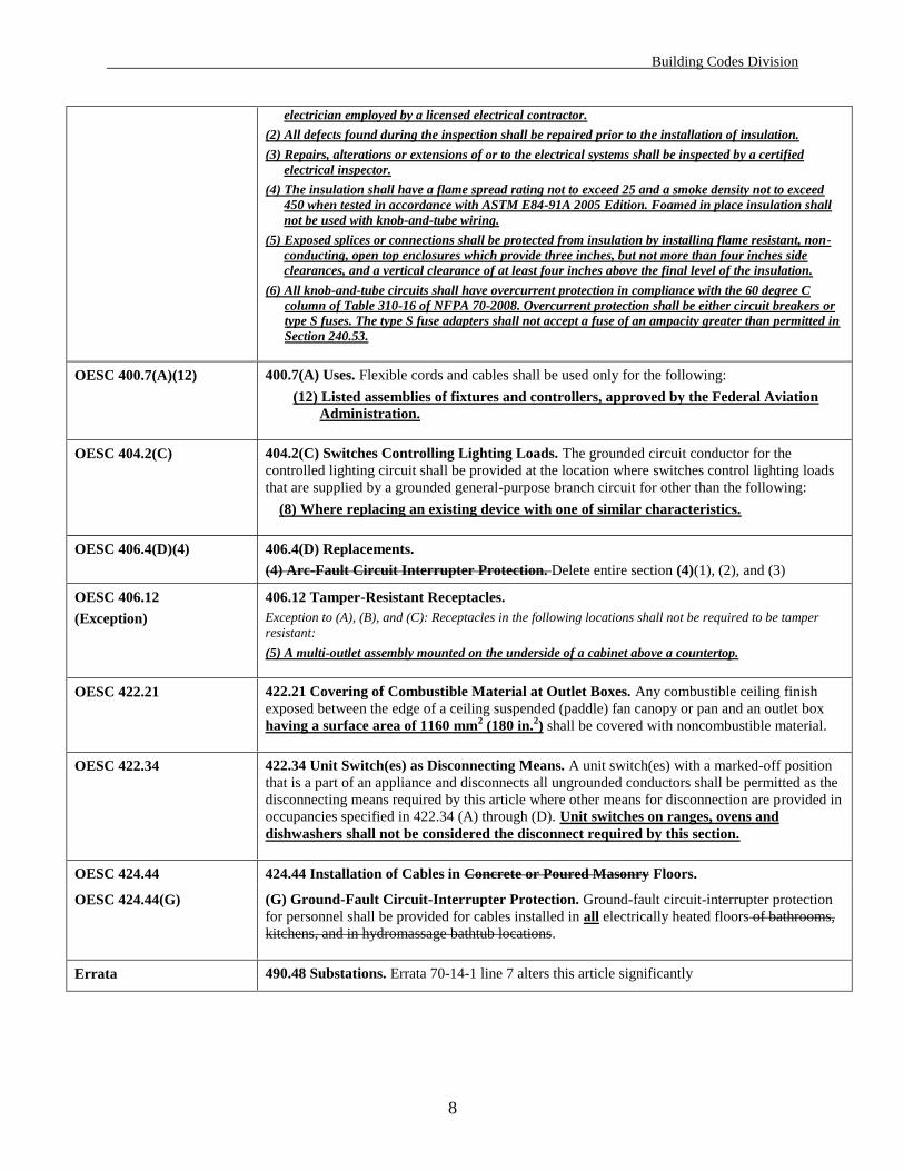
electrician employed by a licensed electrical contractor.
(2) All defects found during the inspection shall be repaired prior to the installation of insulation.
(3) Repairs, alterations or extensions of or to the electrical systems shall be inspected by a certified
electrical inspector.
(4) The insulation shall have a flame spread rating not to exceed 25 and a smoke density not to exceed
450 when tested in accordance with ASTM E84-91A 2005 Edition. Foamed in place insulation shall
not be used with knob-and-tube wiring.
(5) Exposed splices or connections shall be protected from insulation by installing flame resistant, non-
conducting, open top enclosures which provide three inches, but not more than four inches side
clearances, and a vertical clearance of at least four inches above the final level of the insulation.
(6) All knob-and-tube circuits shall have overcurrent protection in compliance with the 60 degree C
column of Table 310-16 of NFPA 70-2008. Overcurrent protection shall be either circuit breakers or
type S fuses. The type S fuse adapters shall not accept a fuse of an ampacity greater than permitted in
Section 240.53.
OESC 400.7(A)(12) 400.7(A) Uses. Flexible cords and cables shall be used only for the following:
(12) Listed assemblies of fixtures and controllers, approved by the Federal Aviation
Administration.
OESC 404.2(C) 404.2(C) Switches Controlling Lighting Loads. The grounded circuit conductor for the
controlled lighting circuit shall be provided at the location where switches control lighting loads
that are supplied by a grounded general-purpose branch circuit for other than the following:
(8) Where replacing an existing device with one of similar characteristics.
OESC 406.4(D)(4) 406.4(D) Replacements.
(4) Arc-Fault Circuit Interrupter Protection. Delete entire section (4)(1), (2), and (3)
OESC 406.12
(Exception)
406.12 Tamper-Resistant Receptacles.
Exception to (A), (B), and (C): Receptacles in the following locations shall not be required to be tamper
resistant:
(5) A multi-outlet assembly mounted on the underside of a cabinet above a countertop.
OESC 422.21 422.21 Covering of Combustible Material at Outlet Boxes. Any combustible ceiling finish
exposed between the edge of a ceiling suspended (paddle) fan canopy or pan and an outlet box
having a surface area of 1160 mm2 (180 in.
2) shall be covered with noncombustible material.
OESC 422.34 422.34 Unit Switch(es) as Disconnecting Means. A unit switch(es) with a marked-off position
that is a part of an appliance and disconnects all ungrounded conductors shall be permitted as the
disconnecting means required by this article where other means for disconnection are provided in
occupancies specified in 422.34 (A) through (D). Unit switches on ranges, ovens and
dishwashers shall not be considered the disconnect required by this section.
OESC 424.44 424.44 Installation of Cables in Concrete or Poured Masonry Floors.
OESC 424.44(G) (G) Ground-Fault Circuit-Interrupter Protection. Ground-fault circuit-interrupter protection
for personnel shall be provided for cables installed in all electrically heated floors of bathrooms,
kitchens, and in hydromassage bathtub locations.
Errata 490.48 Substations. Errata 70-14-1 line 7 alters this article significantly
Building Codes Division
9
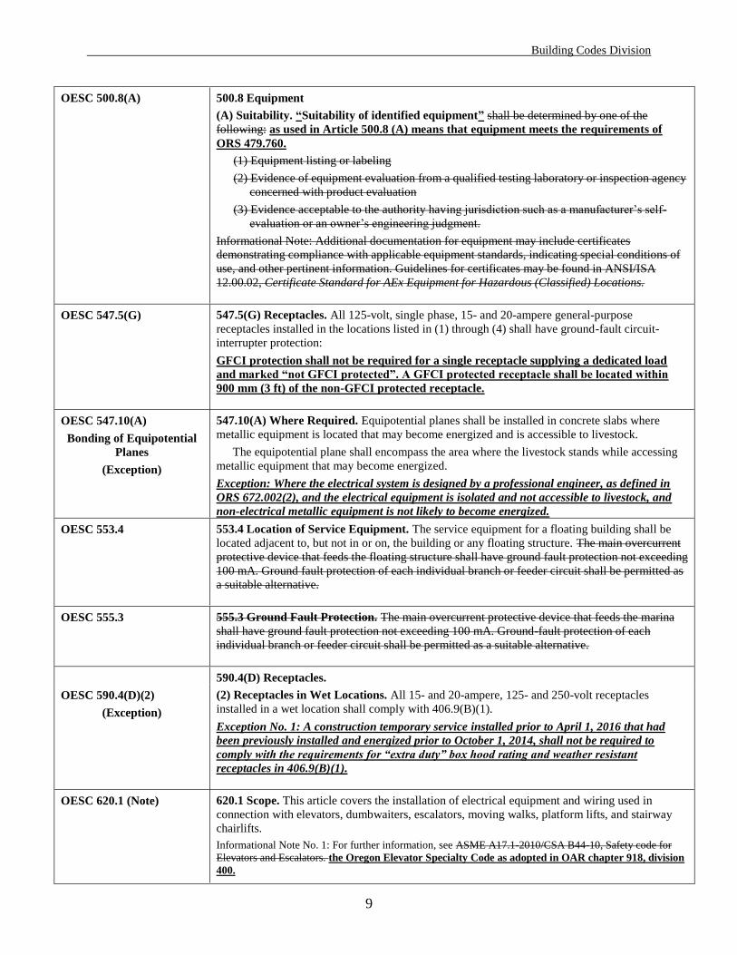
OESC 500.8(A) 500.8 Equipment
(A) Suitability. “Suitability of identified equipment” shall be determined by one of the
following: as used in Article 500.8 (A) means that equipment meets the requirements of
ORS 479.760.
(1) Equipment listing or labeling
(2) Evidence of equipment evaluation from a qualified testing laboratory or inspection agency
concerned with product evaluation
(3) Evidence acceptable to the authority having jurisdiction such as a manufacturer’s self-
evaluation or an owner’s engineering judgment.
Informational Note: Additional documentation for equipment may include certificates
demonstrating compliance with applicable equipment standards, indicating special conditions of
use, and other pertinent information. Guidelines for certificates may be found in ANSI/ISA
12.00.02, Certificate Standard for AEx Equipment for Hazardous (Classified) Locations.
OESC 547.5(G) 547.5(G) Receptacles. All 125-volt, single phase, 15- and 20-ampere general-purpose
receptacles installed in the locations listed in (1) through (4) shall have ground-fault circuit-
interrupter protection:
GFCI protection shall not be required for a single receptacle supplying a dedicated load
and marked “not GFCI protected”. A GFCI protected receptacle shall be located within
900 mm (3 ft) of the non-GFCI protected receptacle.
OESC 547.10(A)
Bonding of Equipotential
Planes
(Exception)
547.10(A) Where Required. Equipotential planes shall be installed in concrete slabs where
metallic equipment is located that may become energized and is accessible to livestock.
The equipotential plane shall encompass the area where the livestock stands while accessing
metallic equipment that may become energized.
Exception: Where the electrical system is designed by a professional engineer, as defined in
ORS 672.002(2), and the electrical equipment is isolated and not accessible to livestock, and
non-electrical metallic equipment is not likely to become energized.
OESC 553.4 553.4 Location of Service Equipment. The service equipment for a floating building shall be
located adjacent to, but not in or on, the building or any floating structure. The main overcurrent
protective device that feeds the floating structure shall have ground fault protection not exceeding
100 mA. Ground fault protection of each individual branch or feeder circuit shall be permitted as
a suitable alternative.
OESC 555.3 555.3 Ground Fault Protection. The main overcurrent protective device that feeds the marina
shall have ground fault protection not exceeding 100 mA. Ground-fault protection of each
individual branch or feeder circuit shall be permitted as a suitable alternative.
590.4(D) Receptacles.
OESC 590.4(D)(2)
(Exception)
(2) Receptacles in Wet Locations. All 15- and 20-ampere, 125- and 250-volt receptacles
installed in a wet location shall comply with 406.9(B)(1).
Exception No. 1: A construction temporary service installed prior to April 1, 2016 that had
been previously installed and energized prior to October 1, 2014, shall not be required to
comply with the requirements for “extra duty” box hood rating and weather resistant
receptacles in 406.9(B)(1).
OESC 620.1 (Note) 620.1 Scope. This article covers the installation of electrical equipment and wiring used in
connection with elevators, dumbwaiters, escalators, moving walks, platform lifts, and stairway
chairlifts.
Informational Note No. 1: For further information, see ASME A17.1-2010/CSA B44-10, Safety code for
Elevators and Escalators. the Oregon Elevator Specialty Code as adopted in OAR chapter 918, division
400.
Building Codes Division
10
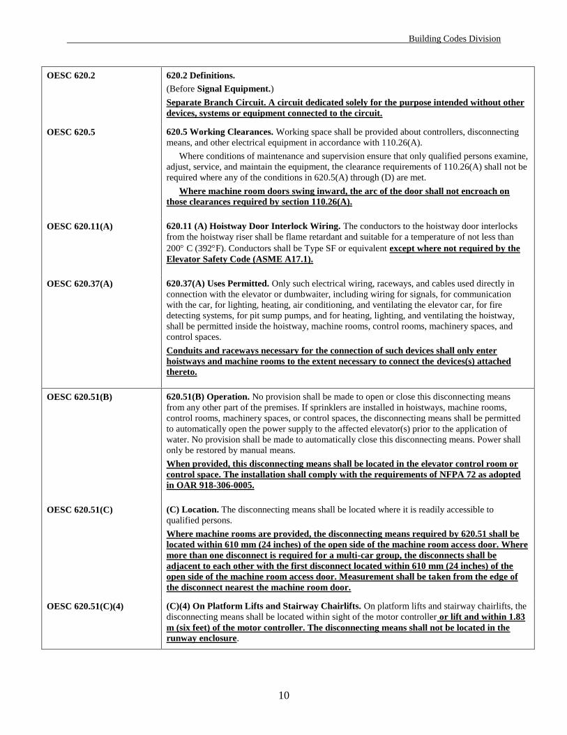
OESC 620.2 620.2 Definitions.
(Before Signal Equipment.)
Separate Branch Circuit. A circuit dedicated solely for the purpose intended without other
devices, systems or equipment connected to the circuit.
OESC 620.5 620.5 Working Clearances. Working space shall be provided about controllers, disconnecting
means, and other electrical equipment in accordance with 110.26(A).
Where conditions of maintenance and supervision ensure that only qualified persons examine,
adjust, service, and maintain the equipment, the clearance requirements of 110.26(A) shall not be
required where any of the conditions in 620.5(A) through (D) are met.
Where machine room doors swing inward, the arc of the door shall not encroach on
those clearances required by section 110.26(A).
OESC 620.11(A) 620.11 (A) Hoistway Door Interlock Wiring. The conductors to the hoistway door interlocks
from the hoistway riser shall be flame retardant and suitable for a temperature of not less than
200 C (392F). Conductors shall be Type SF or equivalent except where not required by the
Elevator Safety Code (ASME A17.1).
OESC 620.37(A) 620.37(A) Uses Permitted. Only such electrical wiring, raceways, and cables used directly in
connection with the elevator or dumbwaiter, including wiring for signals, for communication
with the car, for lighting, heating, air conditioning, and ventilating the elevator car, for fire
detecting systems, for pit sump pumps, and for heating, lighting, and ventilating the hoistway,
shall be permitted inside the hoistway, machine rooms, control rooms, machinery spaces, and
control spaces.
Conduits and raceways necessary for the connection of such devices shall only enter
hoistways and machine rooms to the extent necessary to connect the devices(s) attached
thereto.
OESC 620.51(B) 620.51(B) Operation. No provision shall be made to open or close this disconnecting means
from any other part of the premises. If sprinklers are installed in hoistways, machine rooms,
control rooms, machinery spaces, or control spaces, the disconnecting means shall be permitted
to automatically open the power supply to the affected elevator(s) prior to the application of
water. No provision shall be made to automatically close this disconnecting means. Power shall
only be restored by manual means.
When provided, this disconnecting means shall be located in the elevator control room or
control space. The installation shall comply with the requirements of NFPA 72 as adopted
in OAR 918-306-0005.
OESC 620.51(C) (C) Location. The disconnecting means shall be located where it is readily accessible to
qualified persons.
Where machine rooms are provided, the disconnecting means required by 620.51 shall be
located within 610 mm (24 inches) of the open side of the machine room access door. Where
more than one disconnect is required for a multi-car group, the disconnects shall be
adjacent to each other with the first disconnect located within 610 mm (24 inches) of the
open side of the machine room access door. Measurement shall be taken from the edge of
the disconnect nearest the machine room door.
OESC 620.51(C)(4) (C)(4) On Platform Lifts and Stairway Chairlifts. On platform lifts and stairway chairlifts, the
disconnecting means shall be located within sight of the motor controller or lift and within 1.83
m (six feet) of the motor controller. The disconnecting means shall not be located in the
runway enclosure.

Building Codes Division
11
OESC 620.51(C)(5) (C)(5) Residential installations. A disconnecting means shall be required to be placed within
sight of the controller or lift. Where such devices are supplied with flexible cord and plug
type connectors, the supply receptacle shall be switched by the disconnecting means. The
disconnecting means does not require overcurrent protection, provided such protection is
supplied by the branch circuit overcurrent device. In all other respects the disconnecting
means shall comply with the requirements of this section.
OESC 620.86 620.86 Flexible Metal Conduit. Where flexible metal conduit is utilized between the
disconnecting means specified in Section 620.51 and the elevator controller, an equipment
grounding conductor shall be provided within the raceway and sized per Section 250.122
and Table 250.122.
See Statewide Alternate
Method ruling 09-01
Article 625 This article indicates that electric vehicle charging equipment is considered a
continuous load. The SAM ruling 09-01 recognizes a demand factor table for calculating feeders
and services that supply multiple units of Electric Vehicle Supply Equipment.
OESC 625.43
(New Item)
625.43 Grounding Electrodes. When supplied from equipment with a grounding electrode
system, an additional grounding electrode shall not be required at the electrical vehicle
supply equipment.
OESC 645.2 645.2 Definitions
Critical Operations Data System. An information technology equipment system that has been
designated by the building owner as requires requiring continuous operation. for reasons of
public safety, emergency management, national security, or business continuity.
OESC 645.10 645.10 Disconnecting Means. An approved means shall be provided to disconnect power to all
electronic equipment in the information technology equipment room or in designated zones
within the room. There shall also be a similar approved means to disconnect the power to all
dedicated HVAC systems serving the room or designated zones and shall cause all required
fire/smoke dampers to close. The disconnecting means shall be grouped and identified and
shall be readily accessible at the principal exit doors, or shall comply with either 645.10(A)
or (B).
OESC 645.15
Errata #1, line 13
645.15 Equipment Grounding and Bonding. (Delete second sentence). Power systems derived
within listed information technology equipment that supply information technology systems
through receptacles or cable assemblies supplied as part of this equipment shall not be considered
separately derived for the purpose of applying 250.30.
OESC 680.25(A)(1) 680.25 Feeders.
(A) Wiring Methods.
(1) Feeders. Feeders shall be installed in rigid metal conduit or intermediate metal conduit.
(1) through (6)
Exception: A feeder within a one-family dwelling unit or two-family dwelling unit between
remote panelboard and service equipment shall be permitted to run in flexible metal conduit or
an approved cable assembly that includes an insulated equipment grounding conductor within its
outer sheath.
Errata #2, lines 31 & 32 to
delete text rejected by the
committee
(B) Grounding. (second sentence) For other than (1) existing feeders covered in 680.25(A),
exception, or (2) feeders to separate buildings that do not utilize an insulated equipment
grounding conductor in accordance with 680.25(B)(2), this equipment grounding conductor shall
be insulated.

Building Codes Division
12
OESC 680.42(B)(4) 680.42 Outdoor Installations.
(B) Bonding. [equipotential bonding not required where (1) through (4) are met:]
(4) (second sentence) The height of nonconductive external steps or deck for exit and entry . . .
OESC 690.3
(add Note)
690.3 Other Articles.
Exception: Solar PV systems, equipment, or wiring installed in a hazardous (classified) location shall also
comply with the applicable portions of Articles 500 through 516.
Informational Note: Raceways and conduit systems installed for use with solar photovoltaic
systems may be subject to elevated temperatures and may require the use of expansion fittings and
ambient temperature adjustment. See 300.7(B), and table 310.15(B)(3)(c) for adjustment factors.
OESC 690.11 690.11 Arc-Fault Circuit Protection (Direct Current).
This requirement becomes effective April 1, 2016.
OESC 690.12 690.12 Rapid Shutdown of PV Systems on Buildings.
This requirement becomes effective October 1, 2017.
OESC 690.15 690.15(C) Direct-Current Combiner Disconnect.
If the requirements of 690.12 have not been met, this disconnecting means shall comply
with the following additional requirements:
(1) Located where accessible.
(2) Lockable and externally operable. Other effective disconnecting means such as
electrical interlocking shall be permitted by special permission.
(3) A permanent plaque or directory denoting the location of all disconnecting means
required by 690.13 and 690.14 shall be provided at the service disconnecting means.
OESC 690.31(G)(1) 690.31 Methods Permitted
(G)(1) Embedded in Building Surfaces. Where circuits are Circuit conductors shall not be
embedded in built-up, laminate, or membrane roofing materials in roof areas not covered by PV
modules and associated equipment. , the location of circuits shall be clearly marked using a
marking protocol that is approved as being suitable for continuous exposure to sunlight and
weather.
OESC 690.31(G)(5) (G)(5) Beneath Roofs. Wiring methods shall not be installed within 45 cm (18 in.) of the
roof decking or sheathing except where directly below the roof surface covered by PV
modules and associated equipment. Circuits shall be run perpendicular to the roof
penetration point to supports a minimum of 45 cm (18 in.) below the roof decking.
Informational Note: The 45 cm (18 in.) requirement is to prevent accidental damage from saws used
by fire fighters for roof ventilation during a structure fire.
OESC 690.47 690.47 Grounding Electrode System.
Where a grounding electrode conductor is required by 690.47(A), (B)(C) and (D), it shall
not be smaller than 6AWG copper or 4 AWG aluminum.
OESC 692.6 692.6 Listing Requirement. The fuel cell system shall be evaluated and listed certified for its
intended application prior to installation final approval.
OESC 700 ARTICLE 700 Emergency Systems
Building Officials and inspectors administering and enforcing the state building code under
ORS 455.148 and 455.150, shall assure compliance with Sections 700.28, 701.27, or 708.54
by verifying receipt of a certificate signed by the Engineer of Record or the Signing
Supervisor stating that the proposed installation complies with the selective coordination
requirements of this code.

Building Codes Division
13
OESC 700.28 700.28 Selective Coordination. Emergency system(s) overcurrent devices shall be selectively
coordinated with all supply side overcurrent protective devices.
For the purposes of this section, supply side overcurrent protection means those protective
devices on the emergency system supply side and not on the normal power supply side. The
protection shall be selectively coordinated using the higher of the normal power supply
fault current levels or emergency system fault current levels. Overcurrent devices shall be
selectively coordinated for .01 seconds and greater.
(Exceptions) Exception No. 1: Selective coordination shall not be required between two overcurrent devices located in
series if no loads are connected in parallel with the downstream device.
Exception No. 2: The requirements for selective coordination shall meet the coordination requirements
in effect at the time of the original installation when the installation is being altered, maintained or
repaired. The ground fault sensing function of overcurrent protective devices will only be required to
selectively coordinate with the ground fault sensing functions of other protective devices.
OESC 701.27 701.27 Selective Coordination. Legally required standby system(s) overcurrent devices shall be
selectively coordinated with all supply side overcurrent protective devices.
For the purposes of this section, supply side overcurrent protection means those protective
devices on the emergency system supply side and not on the normal power supply side. The
protection shall be selectively coordinated using the higher of the normal power supply
fault current levels or emergency system fault current levels. Overcurrent devices shall be
selectively coordinated for .01 seconds and greater.
(Exceptions) Exception No. 1: Selective coordination shall not be required between two overcurrent devices located in
series if no loads are connected in parallel with the downstream device.
Exception No. 2: The requirements for selective coordination shall meet the coordination requirements
in effect at the time of the original installation when the installation is being maintained, altered or
repaired. The ground fault sensing function of overcurrent protective devices will only be required to
selectively coordinate with the ground fault sensing functions of other protective devices.
OESC 705.12(D) 705.12(D) Utility-Interactive Inverters. The output of a utility-interactive inverter shall be permitted to be
connected to the load side of the service disconnecting means of the other source(s) at any distribution
equipment on the premises. Where distribution equipment, including switchgear, switchboards, or
panelboards, is fed simultaneously by a primary source(s) of electricity and one or more utility-interactive
inverters, and where this distribution equipment is capable of supplying multiple branch circuits or feeders,
or both, the interconnecting provisions for the utility-interactive inverter(s) shall comply with 705.12(D)(1)
through (D)(6).
OESC 705.12(D)(6) Note: The requirement in 705.12(D)(6) becomes effective April 1, 2016.
OESC 708.1 708.1 Scope. The provisions of this article apply to the installation, operation, monitoring,
control, and maintenance of the portions of the premises wiring system intended to supply,
distribute, and control electricity to designated critical operations areas (DCOA) in the event of
disruption to elements of the normal system.
Critical operations areas and critical operations power systems are those systems so
classed by municipal, state, federal, or other codes by any governmental agency having
jurisdiction or by facility engineering documentation establishing the necessity for such a
designated by the owner of the facility. A building official has no authority to designate or
require designation of an area as requiring a critical operations power system. These
Critical operations power systems can include but are not limited to power systems, HVAC,
fire alarm, security, communications, and signaling for designated critical operations areas.
Building Codes Division
14
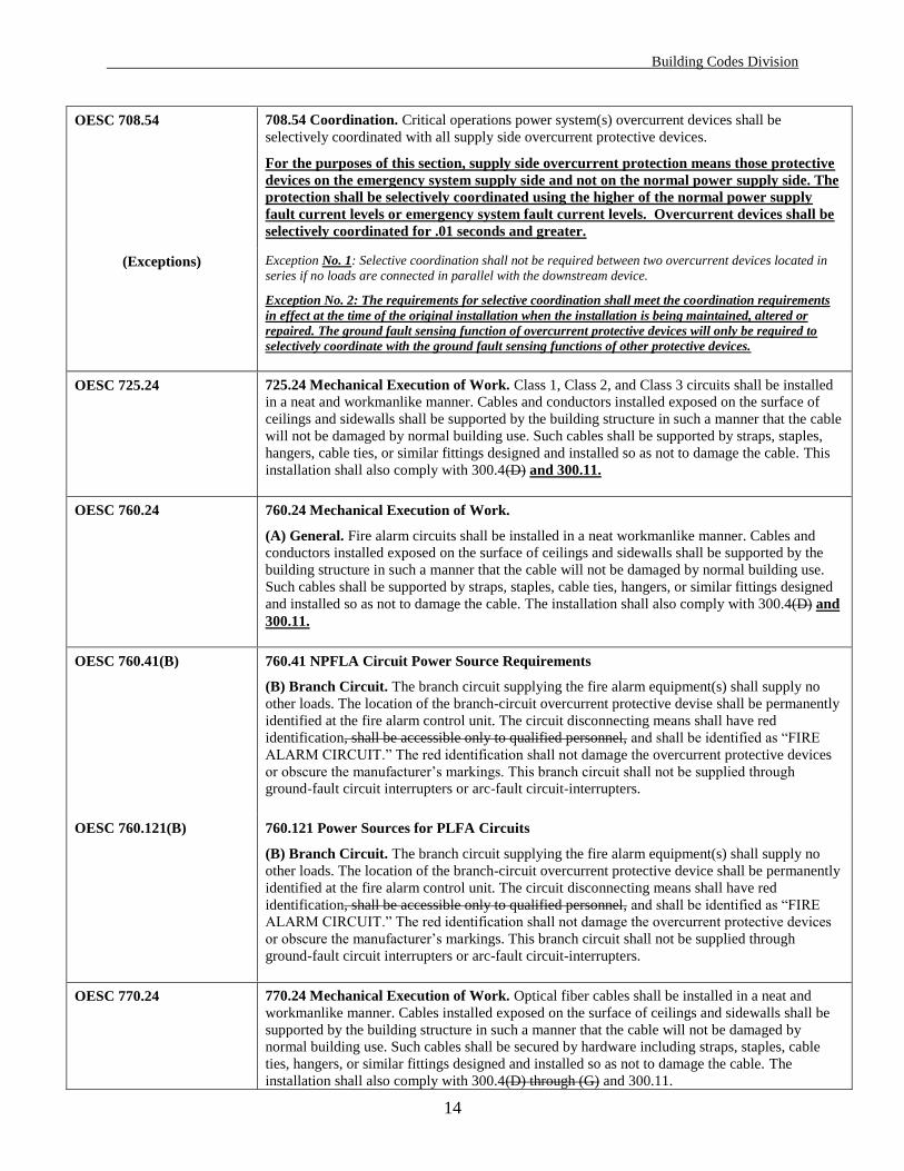
OESC 708.54 708.54 Coordination. Critical operations power system(s) overcurrent devices shall be
selectively coordinated with all supply side overcurrent protective devices.
For the purposes of this section, supply side overcurrent protection means those protective
devices on the emergency system supply side and not on the normal power supply side. The
protection shall be selectively coordinated using the higher of the normal power supply
fault current levels or emergency system fault current levels. Overcurrent devices shall be
selectively coordinated for .01 seconds and greater.
(Exceptions) Exception No. 1: Selective coordination shall not be required between two overcurrent devices located in
series if no loads are connected in parallel with the downstream device.
Exception No. 2: The requirements for selective coordination shall meet the coordination requirements
in effect at the time of the original installation when the installation is being maintained, altered or
repaired. The ground fault sensing function of overcurrent protective devices will only be required to
selectively coordinate with the ground fault sensing functions of other protective devices.
OESC 725.24 725.24 Mechanical Execution of Work. Class 1, Class 2, and Class 3 circuits shall be installed
in a neat and workmanlike manner. Cables and conductors installed exposed on the surface of
ceilings and sidewalls shall be supported by the building structure in such a manner that the cable
will not be damaged by normal building use. Such cables shall be supported by straps, staples,
hangers, cable ties, or similar fittings designed and installed so as not to damage the cable. This
installation shall also comply with 300.4(D) and 300.11.
OESC 760.24 760.24 Mechanical Execution of Work.
(A) General. Fire alarm circuits shall be installed in a neat workmanlike manner. Cables and
conductors installed exposed on the surface of ceilings and sidewalls shall be supported by the
building structure in such a manner that the cable will not be damaged by normal building use.
Such cables shall be supported by straps, staples, cable ties, hangers, or similar fittings designed
and installed so as not to damage the cable. The installation shall also comply with 300.4(D) and
300.11.
OESC 760.41(B) 760.41 NPFLA Circuit Power Source Requirements
(B) Branch Circuit. The branch circuit supplying the fire alarm equipment(s) shall supply no
other loads. The location of the branch-circuit overcurrent protective devise shall be permanently
identified at the fire alarm control unit. The circuit disconnecting means shall have red
identification, shall be accessible only to qualified personnel, and shall be identified as “FIRE
ALARM CIRCUIT.” The red identification shall not damage the overcurrent protective devices
or obscure the manufacturer’s markings. This branch circuit shall not be supplied through
ground-fault circuit interrupters or arc-fault circuit-interrupters.
OESC 760.121(B) 760.121 Power Sources for PLFA Circuits
(B) Branch Circuit. The branch circuit supplying the fire alarm equipment(s) shall supply no
other loads. The location of the branch-circuit overcurrent protective device shall be permanently
identified at the fire alarm control unit. The circuit disconnecting means shall have red
identification, shall be accessible only to qualified personnel, and shall be identified as “FIRE
ALARM CIRCUIT.” The red identification shall not damage the overcurrent protective devices
or obscure the manufacturer’s markings. This branch circuit shall not be supplied through
ground-fault circuit interrupters or arc-fault circuit-interrupters.
OESC 770.24 770.24 Mechanical Execution of Work. Optical fiber cables shall be installed in a neat and
workmanlike manner. Cables installed exposed on the surface of ceilings and sidewalls shall be
supported by the building structure in such a manner that the cable will not be damaged by
normal building use. Such cables shall be secured by hardware including straps, staples, cable
ties, hangers, or similar fittings designed and installed so as not to damage the cable. The
installation shall also comply with 300.4(D) through (G) and 300.11.

Building Codes Division
15
Errata 2, line 42 Significant changes were made in 770.179(F). See Errata for details.
OESC 800.24 800.24 Mechanical Execution of Work. Communications circuits and equipment shall be
installed in a neat and workmanlike manner. Cables installed exposed on the surface of ceilings
and sidewalls shall be supported by the building structure in such a manner that the cable will not
be damaged by normal building use. Such cables shall be secured by hardware, including straps,
staples, cable ties, hangers, or similar fittings designed and installed so as not to damage the
cable. The installation shall also comply with 300.4(D) and 300.11.
OESC 820.24 820.24 Mechanical Execution of Work. Community television and radio distribution systems
shall be installed in a neat and workmanlike manner. Coaxial cables installed exposed on the
surface of ceilings and sidewalls shall be supported by the building structure in such a manner
that the cables will not be damaged by normal building use. Such cables shall be secured by
hardware including straps, staples, cable ties, hangers, or similar fittings designed and installed
so as not to damage the cable. The installation shall also comply with 300.4(D) and 300.11.
OESC 830.24 830.24 Mechanical Execution of Work. Network-powered broadband communications circuits
and equipment shall be installed in a neat and workmanlike manner. Cables installed exposed on
the surface of ceilings and sidewalls shall be supported by the building structure in such a manner
that the cables will not be damaged by normal building use. Such cables shall be secured by
hardware including straps, staples, cable ties, hangers, or similar fittings designed and installed
so as not to damage the cable. The installation shall also conform to 300.4 and 300.11.


![[XLS]upmsp.edu.in · Web view95.8 95 94.2 94 93.8 93.8 93.6 92.8 92.6 92.4 92.4 92.2 92.2 91.8 91.2 91 91 90.8 90.8 90.6 90.6 90.4 90.4 90.4 90.2 90.2 90.2 90 90 89.8 89.6 89.6 89.6](https://static.fdocuments.us/doc/165x107/5ace95d87f8b9a4e7a8b95ec/xlsupmspeduin-view958-95-942-94-938-938-936-928-926-924-924-922-922.jpg)