ode of Practice for uilding Information Modelling (IM) e ... · The IM MEP Workgroup (2015-2016)...
67
Code of Practice for Building Information Modelling (BIM) e-Submission MECHANICAL, ELECTRICAL & PLUMBING (MEP) REQUIREMENTS Version 1.1
Transcript of ode of Practice for uilding Information Modelling (IM) e ... · The IM MEP Workgroup (2015-2016)...

Code of Practice for Building Information Modelling (BIM) e-Submission MECHANICAL, ELECTRICAL & PLUMBING (MEP) REQUIREMENTS
Version 1.1

Code of Practice for BIM e-Submission: MEP Requirements
BCA acknowledges the leadership provided by the BIM Steering Committee in support of the production of the Code of Practice for Building Information Modelling (BIM) e-Submission. This Code of Practice (CP) has been prepared by the Centre for Construction IT on behalf of BCA and the BIM Steering Committee. ©Building and Construction Authority 2017 Building and Construction Authority 52 Jurong Gateway Road, #11-01 Singapore 608550 www.bca.gov.sg First published October 2016 While every effort has been made to ensure the accuracy and quality of information contained in this publication, the Building and Construction Authority, its employees, agents or industry partners can take no responsibility for the subsequent use of this information, nor for any errors or omissions that it may contain.
Cover image and design courtesy of RSP Architects Planners & Engineers (Pte) Ltd, Squire Mech and BCA Academy

Code of Practice for BIM e-Submission: MEP Requirements
ACKNOWLEDGEMENTS The development of this Code of Practice has been a collaborative effort among a cadre of
very knowledgeable consultants and processing officers from different regulatory/technical
agencies. Significant contributors are listed below:
Regulatory/Technical Agencies
Name Agency
Er. Lee Chee Keong
Er. Wong Siew Heng
Mr. Ng Kok Lam
Mr. Pang Mun Hung
Mr. Liu Ziwen
Building and Construction Authority
Mr. Liew Khee Boon City Gas Pte Ltd
Mr. Seah Koon Chye Info Communication Media Development Authority
Mr. Joseph Foo National Environment Agency
Ms. Olivia Teo
Ms. Ang Liew Kwee
Public Utilities Board
Maj. Tan Chung Yee Singapore Civil Defence Force

Code of Practice for BIM e-Submission: MEP Requirements
ii
BIM MEP Workgroup
The BIM MEP Workgroup (2015-2016) comprises the following:
Name Company
Mr. Yu, Ka Fa Gordon AECOM Singapore Pte. Ltd.
Ms. Maw Maw Khin Arup Singapore Private Limited
Mr. Lim Kok Keong DP Engineers Pte. Ltd.
Ms. Serene Lim KTP International Pte. Ltd.
Ms. Boey Lai Yin Parsons Brinckerhoff Pte. Ltd.
Ms. Ivana Sadikin Rankine&Hill (Singapore) Pte Ltd.
Mr. Joseph Koh
Er. Koh Kin Teng
Squire Mech Pte. Ltd.
Mr. Saw Thant Lwin Tun
Ms. Pansy Peh
Surbana Jurong Consultants Pte. Ltd.
Ms. Chong Mei Syn T.Y. Lin International Pte. Ltd.
Mr. Felix Batad United Project Consultants Pte. Ltd.

Code of Practice for BIM e-Submission: MEP Requirements
Copyright © 2016 Building and Construction Authority. All Rights Reserved. 1
TABLE OF CONTENTS
1 BCA - CIVIL DEFENCE (CD) MECHANICAL AND ELECTRICAL PLANS IN PUBLIC SHELTERS _ 4
1.1 General Requirements _____________________________________________ 4
1.2 Air-Conditioning & Mechanical Ventilation (ACMV) System/ Environmental Control
Systems (ECS) ____________________________________________________ 4
1.3 Water Supply, Sewerage and Drainage Systems (WSSDS) and Fire Protection
Systems (FPS) ____________________________________________________ 6
1.4 Electrical Power System (ELECT), Communications System (COMMS) and CD Door
Monitoring System (DMS) __________________________________________ 8
2 BCA - CIVIL DEFENCE (CD) MECHANICAL AND ELECTRICAL PLANS IN TRANSIT SHELTERS _____________________________________________________________ 10
2.1 General Requirements ____________________________________________ 10
2.2 Environmental Control Systems (ECS) ________________________________ 10
2.3 Water Supply, Sewerage and Drainage Systems (WSSDS) and Fire Protection
Systems (FPS) ___________________________________________________ 12
2.4 Electrical Power System (Elect), Communications System (Comms), CD Door
Monitoring System (Dms) And Equipment Monitoring System (Ems) ________ 14
3 CITY GAS SUBMISSION REQUIREMENTS _____________________________________ 17
3.1 General Requirements ____________________________________________ 17
4 IMDA TELECOMMUNICATION FACILITY CO-ORDINATION COMMITTEE SUBMISSION REQUIREMENT (IDA TFCC SUBMISSIONS) ____________________________________ 24
4.1 General Requirements ____________________________________________ 24
5 NEA - CENTRAL BUILDING PLAN DEPARTMENT AND PUB-WATER RECLAMATION (NETWORK) DEPARTMENTSUBMISSION REQUIREMENT (NEA-CBPD AND PUB-WRN) _ 29
5.1 General Requirements for all CBPD/ PUB-WRN Submissions ______________ 29
5.2 Detailed Plan on Sanitary Works (for Sanitary Plumbing & Drainage System/ Sewer
Connection) ____________________________________________________ 29
5.3. As-built Plan for TOP/CSC – Sanitary Works (Sanitary Plumbing & Drainage System/
Sewer Connection) _______________________________________________ 33
6 PUB - WATER SUPPLY (NETWORK) SUBMISSION REQUIREMENT (PUB-WTR SUBMISSIONS) _________________________________________________________ 38
6.1 General Requirements ____________________________________________ 38

Code of Practice for BIM e-Submission: MEP Requirements
Copyright © 2016 Building and Construction Authority. All Rights Reserved. 2
6.2 2D Views _______________________________________________________ 38
6.3. Part 3D BIM Model _______________________________________________ 43
7 SCDF FIRE SAFETY AND SHELTER DEPARTMENT (FSSD) REQUIREMENTS____________ 45
7.1 General Requirements for All FSSD Submissions ________________________ 45
7.2 2D Views _______________________________________________________ 45
7.3 Floor Plan generated from BIM Model and BIM Models __________________ 46
CORE INFORMATION FOR BIM OBJECTS ________________________________________ 52
COLOUR STANDARDS _______________________________________________________ 59
SUBMISSION FORMAT SUMMARY _____________________________________________ 62
LIST OT FIGURES ___________________________________________________________ 62
CODE OF PRACTICE FOR BIM E-SUBMISSION SERIES_______________________________ 63

Code of Practice for BIM e-Submission: MEP Requirements
Copyright © 2016 Building and Construction Authority. All Rights Reserved. 3
BUILDING AND
CONSTRUCTION AUTHORITY
(BCA)

Code of Practice for BIM e-Submission: MEP Requirements
Copyright © 2016 Building and Construction Authority. All Rights Reserved. 4
AGENCY - SPECIFIC REQUIREMENTS
1 BCA - CIVIL DEFENCE (CD) MECHANICAL AND ELECTRICAL PLANS IN PUBLIC SHELTERS
1.1 General Requirements
The Qualified Person (QP) shall familiarise with the CD Technical Requirements (TR) for S1-S5
Public Shelters, before preparing the respective CD ACMV System/ECS, Fire Protection System
(FPS) and Water Supply, Sewerage and Drainage System (WSSDS) and CD Door Monitoring
System (DMS) BIM submissions for Public Shelters. The submissions shall comprise native BIM
full 3D models, 2D plans, sections & elevations and part 3D models and part 2D plans, sections
& elevations, which are illustrative with details and dimensions, to show compliance with the
CD Requirements. The level of detail and information shown in the 2D plans, sections and
elevations shall be similar as that of traditional (2D) mechanical & electrical plan submissions.
The submissions shall comprehensively cover important aspects of the shelters described in
the following sections.
The QP shall consult the Civil Defence Shelter Engineering Department of BCA for clarification.
1.2 Air-Conditioning & Mechanical Ventilation (ACMV) System/ Environmental Control Systems (ECS)
1.2.1 Shelter Layout
A. Full BIM 3D Models
The 3D model shall show the entire CD shelter, CD modes of operation and include the
following:
1. The whole ACMV/ ECS system, indicating clearly the ACMV/ ECS CD related rooms,
equipment, accessories and, services routings. These shall include but are not
limited to:
a) All ACMV/ ECS CD related plantrooms e.g. chiller plantroom, air handling unit
(AHU) room and CD ancillary rooms, e.g. CD first aid room, CD pantry, etc.;

Code of Practice for BIM e-Submission: MEP Requirements
Copyright © 2016 Building and Construction Authority. All Rights Reserved. 5
b) CD related (dual purpose) equipment e.g. chillers, AHUs, pumps, electrical panels,
control panels, etc., and CD related (dedicated) equipment, blast valves, etc.; and
c) Services routings, sizes and setting-out from ceiling slabs and walls for ducts,
pipes, cable trays, conduits, etc.
B. 2D Plans, Sections and Elevations generated from BIM Model
The 2D plans, sections and elevations shall illustrate clearly the following:
a) General layout at all levels or space associated with the CD shelter.
b) All ACMV/ ECS CD related plantrooms and ancillary rooms, locations, setting-out
and performance capacities of CD related equipment, accessories, services sizes,
layout and routings, and their supports;
c) CD dry toilets; and
d) All ACMV/ ECS CD related schematics and typical installation details.
C. Part BIM 3D Models
The Part 3D models shall show the ACMV/ ECS CD related rooms, equipment, accessories,
services routings and their supports. These shall include but are not limited to:
a) Plantrooms and ancillary rooms: Locations, layout and positioning of the CD related
(dual purpose) e.g. AHUs, chillers, pumps, electrical panels, control panels, etc. and
(dedicated) equipment, e.g. blast valves, ‘dirty air’ filters, etc. complete with their
accessories and services, i.e. ducting, piping, cable trays, conduits, etc.;
b) ACMV/ ECS services routing, e.g. ducts, pipes, cable trays, conduits, etc. complete
with their supports; and
c) CD dry toilets.

Code of Practice for BIM e-Submission: MEP Requirements
Copyright © 2016 Building and Construction Authority. All Rights Reserved. 6
D. Part BIM 2D Plans, Sections and Elevations
The 2D plans, sections and elevations of the above-mentioned Part 3D models shall illustrate
clearly the following:
a) Locations, clear dimensions and performance capacities of CD related equipment,
accessories, services and their supports from ceilings, walls and floors;
b) Operation and Maintenance access and clearance spaces for CD related
equipment and services; and
c) Services penetrations through floor and wall openings: Locations, sizes and types
of sealing devices e.g. multi-cable transits (MCTs), puddle flanges, etc.
1.3 Water Supply, Sewerage and Drainage Systems (WSSDS) and Fire Protection Systems (FPS)
1.3.1 Shelter Layout
A. Full BIM 3D Model
The 3D model shall show the entire CD shelter, CD modes of operation and shall include the
following:
a) The whole WSSDS and FP Systems indicating clearly the WSSDS CD related rooms,
equipment, accessories and services routings. These shall include but are not
limited to:
i. All WSSDS and FPS CD related plantrooms e.g. water distribution control
room, ejector pump room, drainage pump room, etc. and CD ancillary rooms
e.g. CD first aid room, CD pantry, etc.;
ii. All WSSDS CD dedicated drinking water pumps, etc.;
iii. WSSDS CD services routings, sizes and setting-out from ceiling slabs and
walls for pipes, cable trays, trunkings, conduits, etc.; and
iv. All FPS CD related equipment, viz. isolation valves, removable short pipe
section complete with quick coupling end caps and straps.

Code of Practice for BIM e-Submission: MEP Requirements
Copyright © 2016 Building and Construction Authority. All Rights Reserved. 7
B. Full BIM 2D Plans, Sections and Elevations
The 2D plans, sections and elevations shall illustrate clearly the following: -
a) General layout at all levels or space associated with the CD shelter;
b) All WSSDS and FPS CD related plantrooms and ancillary rooms, CD WSSDS related
equipment and their performance capacities, accessories, services sizes, layout,
setting-out and routings and their related supports; and
c) CD dry toilets.
C. Part BIM 3D Model
The Part 3D model shall show the WSSDS CD related rooms, equipment, accessories and
services routings. These shall include but are not limited to:
a) Plantrooms and ancillary rooms: Locations, layout and positioning of the CD related
equipment complete with their accessories and services, i.e. piping, cable trays,
conduits, etc.;
b) WSSDS and FPS services routings; and
c) CD dry toilets.
D. Part BIM 2D Plans, Sections and Elevations
The 2D plans, sections and elevations of the above-mentioned Part 3D models shall illustrate
clearly the following:
a) Locations, clear dimensions and performance capacities of CD related equipment,
accessories, services and supports from ceilings, floors and walls;
b) Operation and Maintenance access and clearance spaces for CD related equipment
and services; and
c) Services penetrations through floor and wall openings: Locations, sizes and types
of sealing devices e.g. multi-cable transits (MCTs), puddle flanges, etc.

Code of Practice for BIM e-Submission: MEP Requirements
Copyright © 2016 Building and Construction Authority. All Rights Reserved. 8
1.4 Electrical Power System (ELECT), Communications System (COMMS) and CD Door Monitoring System (DMS)
1.4.1 Shelter Layout
A. Full BIM 3D Models
The 3D model shall show the entire CD shelter and include the following:
a) The whole ELECT, COMMS and CD DMS systems indicating clearly the CD related
rooms, equipment, accessories and services routings. These shall include but are
not limited to:
i. All CD related plant rooms, e.g. generator room, switch rooms, closets, etc.;
ii. CD related equipment, e.g. generator system, switchboards,
communication system panels, etc.; and
iii. Services routings, sizes, spacings and setting-out from ceilings and walls i.e.
cable trays, trunkings, conduits, fuel and vent pipes, exhaust pipes, etc.
B. Full BIM 2D Plans, Sections and Elevations
The 2D plans, sections and elevations shall illustrate clearly the following:
a) General layout at all levels or space associated with the CD shelter;
b) All CD related plant rooms and ancillary rooms, locations, setting-out and
performance capacities of CD related equipment, accessories and services sizes,
layout and routings and their supports; and
c) All CD related single line diagrams, schematics and typical installation details.

Code of Practice for BIM e-Submission: MEP Requirements
Copyright © 2016 Building and Construction Authority. All Rights Reserved. 9
C. Part BIM 3D Models
The Part 3D model shall show the CD related rooms, equipment, accessories and services
routings. These shall include but are not limited to:
a) Plant rooms and ancillary rooms: Locations, layout and positioning of the CD
related equipment, e.g. generator system, switchboards, communication system
panels, etc, complete with their accessories and services, i.e. cable trays, trunkings,
conduits, fuel and vent pipes, exhaust pipes, etc.; and
b) Services routings, e.g. cable trays, trunkings, conduits, fuel and vent pipes, exhaust
pipes, etc.
D. Part BIM 2D Plans, Sections and Elevations
The 2D plans, sections and elevations of the above-mentioned Part 3D models shall illustrate
clearly the following:
a) Locations, clear dimensions and performance capacities of CD related equipment,
accessories, services and their supports from ceilings, walls and floors;
b) Operation and maintenance access and clearance spaces for CD related
equipment and services; and
c) Services penetrations on floor and wall openings, locations, sizes and types of
sealing devices e.g. multi-cable transits (MCTs), puddle flanges, etc.

Code of Practice for BIM e-Submission: MEP Requirements
Copyright © 2016 Building and Construction Authority. All Rights Reserved. 10
2 BCA - CIVIL DEFENCE (CD) MECHANICAL AND ELECTRICAL PLANS IN TRANSIT SHELTERS
2.1 General Requirements
The Qualified Person (QP) shall familiarise himself with the CD Technical Requirements (TR) for
S10 to S29 Public Shelters or CD Shelter Requirements for MRT Stations, whichever is
applicable, before preparing the respective CD Environmental Control Systems (ECS), Water
Supply, Sewerage and Drainage Systems (WSSDS), Fire Protection Systems (FPS), Electrical
Power System (Elect), Communications System (Comms), CD Door Monitoring System (DMS)
and CD Equipment Monitoring System (EMS) BIM submissions for Transit CD shelters. The
submissions shall comprise native BIM full 3D models, 2D plans, sections and elevations and
part 3D models and part 2D plans, sections and elevations, which are illustrative with details
and dimensions, to show compliance with the CD requirements. The submissions shall
comprehensively cover important aspects of the shelter described in the following sections:
2.2 Environmental Control Systems (ECS)
2.2.1 Shelter Layout
A. Full BIM 3D Models
The 3D model shall show the entire CD shelter, CD modes of operation and include the
following:
a) The whole ECS system, indicating clearly the ECS CD related rooms, equipment,
accessories and, services routings. These shall include but are not limited to:
i. All ECS CD related plantrooms e.g. chiller plantroom, air handling unit
(AHU) room, etc. and CD ancillary rooms, e.g. CD first aid room, CD pantry,
etc.;
ii. CD related (dual purpose) equipment e.g. chillers, AHUs, pumps, electrical
panels, control panels, etc., and CD related (dedicated) equipment, e.g.
blast valves, gas filters, etc.; and
iii. Services routings, sizes and setting-out from ceiling slabs and walls for
ducts, pipes, cable ladders, trays, conduits, etc.

Code of Practice for BIM e-Submission: MEP Requirements
Copyright © 2016 Building and Construction Authority. All Rights Reserved. 11
B. Full BIM 2D Plans, Sections and Elevations
The 2D plans, sections and elevations of the above-mentioned 3D models shall illustrate clearly the following:
a) General layout at ground level, concourse, platform and any other level or space
associated with the CD shelter, such as mezzanine floors and subway connections;
b) All ECS CD related plantrooms and ancillary rooms, locations, setting-out and
performance capacities of CD related equipment, accessories, services sizes,
layout and routings, and their supports;
c) Permanent toilets e.g. male toilets, female toilets, etc. and CD dry toilets; and
d) All ECS CD related schematics and typical installation details.
C. Part BIM 3D Models
The Part 3D models shall show the ECS CD related rooms, equipment, accessories, services
routings and their supports. These shall include but are not limited to:
a) Plantrooms and ancillary rooms: Locations, layout and positioning of the CD
related (dual purpose) e.g. chillers, AHUs, pumps, electrical panels, control panels,
etc. and CD related (dedicated) equipment, e.g. blast valves, gas filters, etc.
complete with their accessories and services, i.e. ductings, pipings, cable trays,
conduits, etc.;
b) ECS services routing, e.g. ducts, pipes, cable trays, conduits, etc.; and
c) Permanent toilets and CD dry toilets.
D. Part BIM 2D Plans, Sections and Elevations
The 2D plans, sections and elevations of the above-mentioned Part 3D models shall illustrate
clearly the following:
a) Locations, clear dimensions, positioning and performance capacities of CD related
equipment, accessories, services and their supports from ceilings, walls and
floors;
b) Operation and Maintenance access and clearance spaces for CD related
equipment and services; and
c) Services penetrations through floor and wall openings: Locations, sizes and types
of sealing devices e.g. multi-cable transits (MCTs), puddle flanges, etc.

Code of Practice for BIM e-Submission: MEP Requirements
Copyright © 2016 Building and Construction Authority. All Rights Reserved. 12
2.3 Water Supply, Sewerage and Drainage Systems (WSSDS) and Fire Protection Systems (FPS)
2.3.1 Shelter Layout
A. Full BIM 3D Model
The 3D model shall show the entire CD shelter, CD modes of operation and shall include the
following:
a) The whole WSSDS and FPS systems, indicating clearly the WSSDS and FPS CD
related rooms, equipment, accessories and services routings. These shall include
but are not limited to the following:
i. All WSSDS and FPS CD related plantrooms e.g. water distribution control
room, ejector pump room, drainage pump room, sprinkler pump room, etc.
and CD ancillary rooms e.g. CD first aid room, CD pantry, etc.;
ii. All WSSDS CD dual purpose and dedicated drinking water pumps, UV
purifier, etc., and all FPS CD related equipment viz. isolation valves and
removable short pipe section complete with quick coupling end caps; and
iii. WSSDS and FPS CD services routings, sizes and setting-out from ceiling
slabs and walls for pipes, cable ladders, trays, trunkings, etc.
B. Full BIM 2D Plans, Sections and Elevations
The 2D plans, sections and elevations shall illustrate clearly the following:
a) General layout at ground level, concourse, platform and any other level or space
associated with the CD shelter, such as mezzanine floors and subway connections;
b) All WSSDS and FPS CD related plantrooms and ancillary rooms, CD WSSDS related
equipment and their performance capacities, accessories, layout, setting-out and
service sizes and routings and their related supports; and
c) CD permanent toilets (e.g. male and female toilets) and CD dry toilets.

Code of Practice for BIM e-Submission: MEP Requirements
Copyright © 2016 Building and Construction Authority. All Rights Reserved. 13
C. Part BIM 3D Model
The Part 3D model shall show the FPS and WSSDS CD related rooms, equipment, accessories
and services routings. These shall include but are not limited to:
a) Plantrooms and ancillary rooms: Locations, layout and positioning of the CD
related equipment complete with their accessories and services, i.e. piping, cable
trays, conduits, etc.;
b) FPS and WSSDS services routings; and
c) Permanent toilets and CD dry toilets.
D. Part BIM 2D Plans, Sections and Elevations
The 2D plans, sections and elevations of the above-mentioned Part 3D models shall illustrate
clearly the following:
a) Locations, clear dimensions, positioning and performance capacities of CD related
equipment, accessories, services and their supports from ceilings, floors and
walls;
b) Operation and Maintenance access and clearance spaces for CD related
equipment and services; and
c) Services penetrations through floor and wall openings: Locations, sizes and types
of sealing devices e.g. multi-cable transits (MCTs), puddle flanges, etc.

Code of Practice for BIM e-Submission: MEP Requirements
Copyright © 2016 Building and Construction Authority. All Rights Reserved. 14
2.4 Electrical Power System (Elect), Communications System (Comms), CD Door Monitoring System (Dms) And Equipment Monitoring System (Ems)
2.4.1 Shelter Layout
A. Full BIM 3D Models
The 3D model shall show the entire CD shelter and include the following:
a) The whole ELECT, COMMS, DMS and EMS systems, indicating clearly the CD
related rooms, equipment, accessories and services routings. These shall include
but are not limited to the following:
i. All CD related plantrooms, e.g. emergency main switchroom, distribution
board room, generator room, and ancillary rooms e.g. CD first aid room, CD
pantry, etc.;
ii. CD related (dual purpose) equipment, e.g. electrical panels, control panels,
etc. and CD related (dedicated) equipment e.g. generator system,
emergency main switchboards, etc.; and
iii. Services routings, sizes, spacings and setting-out from ceilings and walls i.e.
cable ladders, trays, trunkings, generator exhaust pipes, fuel in-fill and vent
pipes, etc.
B. Full BIM 2D Plans, Sections and Elevations
The 2D plans, sections and elevations shall illustrate clearly the following:
a) General layout at ground level, concourse, platform and any other level or space
associated with the CD shelter, such as mezzanine floors and subway connections;
b) All CD related plantrooms and ancillary rooms, locations, setting-out and
performance capacities of CD related equipment, accessories and services sizes,
layout and routings and their supports; and
c) All CD related schematics and typical installation details.

Code of Practice for BIM e-Submission: MEP Requirements
Copyright © 2016 Building and Construction Authority. All Rights Reserved. 15
C. Part BIM 3D Models
The Part 3D models shall show the CD related rooms, equipment, accessories and services
routings. These shall include but are not limited to the following:
a) Plantrooms and ancillary rooms: Locations, layout and positioning of the CD
related (dual purpose) equipment, e.g. electrical panels, control panels, etc. and
CD related (dedicated) equipment e.g. generator system, emergency main
switchboard, etc. complete with their accessories and services, i.e. cable ladders,
trays, trunkings, generator exhaust pipes, fuel in-fill and vent pipes, etc.; and
b) Services routings, e.g. cable ladders, trays, trunkings, generator exhaust pipes,
fuel in-fill and vent pipes, etc.
D. Part BIM 2D Plans, Sections and Elevations
The 2D plans, sections and elevations of the above-mentioned Part 3D models shall illustrate
clearly the following:
a) Locations, clear dimensions, positioning and performance capacities of CD related
equipment, accessories, services and their supports from ceilings, walls and
floors;
b) Operation and Maintenance access and clearance spaces for CD related
equipment and services; and
c) Services penetrations through floor and wall openings, locations, sizes and types
of sealing devices e.g. multi-cable transits (MCTs), puddle flanges, etc.

Code of Practice for BIM e-Submission: MEP Requirements
Copyright © 2016 Building and Construction Authority. All Rights Reserved. 16
CITY GAS PTE LTD

Code of Practice for BIM e-Submission: MEP Requirements
Copyright © 2016 Building and Construction Authority. All Rights Reserved. 17
3 CITY GAS SUBMISSION REQUIREMENTS
3.1 General Requirements
This document provides the general guidelines for professional engineers and licensed gas
service workers to comply when they submit BIM model to City Gas. The professional
engineers/ licensed gas service workers shall ensure the design of the gas installation and all
gas service works carried out on the gas installation comply with the requirements and
provisions of the latest revision of the following:
The Gas Act (Cap 116A);
The Gas (Supply) Regulations
The Gas Supply Code
Singapore Standard, SS 608, Code of Practice for Gas Installation
City Gas Handbook on Gas Supply
Any other relevant rules, regulations and Codes of Practice
CityGas Submission Documents
2D Views BIM Model
Site and location plan
Notes and legend page
Schematic drawing
Typical detail drawing
Floor plans generated from BIM
model
Part 3D Model
A. 2D Views
Each submission plan shall bear the declaration on the right side column of the layout sheet.
A blank space of 90 mm (w) x 60 mm (h) shall be provided on the right side column for City
Gas internal use. Please refer to City Gas Handbook on Gas Supply for Designated
Representative’s declaration required by City Gas.

Code of Practice for BIM e-Submission: MEP Requirements
Copyright © 2016 Building and Construction Authority. All Rights Reserved. 18
The submission of plans for approval by Designated Representative shall consist of the
following plans:
1. Site and Location Plan
Location Plan Site Plan
o Location plan with the development
boundary line highlighted in red.
o Plan shall prepare at a scale of 1:500 or
1:1000;
o Highlight the development boundary line
in red;
o Plan shall have grid lines and dimension
indicated;
o Plan shall show the specifications of pipe
installation; and
o Indicate the location of gas connection.

Code of Practice for BIM e-Submission: MEP Requirements
Copyright © 2016 Building and Construction Authority. All Rights Reserved. 19
Fig. 1 - Example: Site Plan
Image credit to AECOM
Example: Location Plan
Image credit to AECOM

Code of Practice for BIM e-Submission: MEP Requirements
Copyright © 2016 Building and Construction Authority. All Rights Reserved. 20
2. Schematic Diagram and Detail Plan
a) Submit schematic diagram of gas installation of each building; and
b) Typical detail of gas installation (such as gas duct ventilation, trench, box up
detail, meter installation, duckfoot support design).
Fig. 2 - Example: Schematic Diagram
B. Plans generated from BIM model and Part 3D BIM Model
a) Plan shall preferably be submitted at a scale of 1:100 or 1:200;
b) Plan shall have grid lines and dimension indicated;
c) Indicate the location of the gas connection;
d) Each compartment/space shall indicate clearly with annotations of:
o The purpose of the compartment/space; and
o The mode of ventilation of the compartment/space.
e) Plan shall show the specifications of gas pipe and pipe sleeve; and
f) Roof plan shall be submitted if the gas duct ventilation is proposed at roof level.
g) Part 3D BIM model may be submitted for better visualization of gas installation
such as gas duct ventilation, service valve chamber, etc.
Image credit to UPC

Code of Practice for BIM e-Submission: MEP Requirements
Copyright © 2016 Building and Construction Authority. All Rights Reserved. 21
Fig. 3 - Example: Plans generated from BIM Model
Fig. 4 - Example: Part 3D BIM Model
Image credit to UPC

Code of Practice for BIM e-Submission: MEP Requirements
Copyright © 2016 Building and Construction Authority. All Rights Reserved. 22
C. File Deliverable Requirements
Submission plans must be saved in BIM format (Please refer to <Submission Format
Summary> of this document). Each plan shall be submitted individually in its own file.
D. Resubmission/amendment submission
For resubmission/amendment submission, Designated Representative is required to submit
only the deviated plans for approval.
E. As-built submission
As-built plans inclusive of line diagram for the installation are to be submitted together with
the application for final pressure test. The as-built plans which show the actual pipe
installation have to be endorsed by the Designated Representative responsible for the
installation. The Designated Representative shall submit one set of as-built plan to owner.
F. Pipe materials and sizes used for gas installation
The table below shows the pipe materials and sizes commonly used for gas installation.
Material (Standards) Size (mm) Types of Joints (Standards)
Polyethylene pipes 32, 63, 125, 180, 250, 315
Butt fusion Electrofusion joint
Ductile iron pipes 100, 150, 200, 300 Bolted gland joint
Galvanised iron pipes (seamless & heavy gauge type)
20, 25, 32, 40, 50, 80, 100
Threads joint (Below 100mm diameter) Flange joint (100mm diameter and above)
Steel pipes (Seamless type) 20, 25, 32, 40, 50, 80, 100, 150, 200, 300
Welded joint
Copper pipes (seamless & half hard type)
15, 22, 28 Compression joint Capillary joint

Code of Practice for BIM e-Submission: MEP Requirements
Copyright © 2016 Building and Construction Authority. All Rights Reserved. 23
INFO-COMMUNICATIONS
MEDIA DEVELOPMENT
AUTHORITY (IMDA)

Code of Practice for BIM e-Submission: MEP Requirements
Copyright © 2016 Building and Construction Authority. All Rights Reserved. 24
4 IMDA TELECOMMUNICATION FACILITY CO-ORDINATION COMMITTEE SUBMISSION REQUIREMENT (IDA TFCC SUBMISSIONS)
4.1 General Requirements
The documents to be submitted shall meet the requirements specified under chapter 3 of
the Code of Practice for Info-communication Facilities in Buildings (COPIF). The plans shall
contain but not limited to the sectional and elevation drawings of the building. All
dimensions and grids shall be indicated clearly on the plans.
IDA-TFCC Submission Documents
2D View BIM Model
Site and location plan
Notes and legend page
Schematic drawing
Main Distribution Frame (MDF
Room)
Telecommunication Equipment
Room (TER)
Telecommunication Risers
Floor plans generated from BIM
model
A. 2D Views
1. Site and Location Plan
The plans shall contain the following:
Site Plan Location Plan o The means of access to the site and to the
perimeter of each building;
o Distances between buildings and/or
structures; and
o The existing (if any) and proposed
underground telecommunication system at
the site.
o The location of the lot relative to its
neighboring lots; and
o The various roads constituting the
access layout to the lot.

Code of Practice for BIM e-Submission: MEP Requirements
Copyright © 2016 Building and Construction Authority. All Rights Reserved. 25
Fig. 5 - Example: Site Plan
Fig. 6 - Example: Location Plan
Image credit to Surbana Jurong

Code of Practice for BIM e-Submission: MEP Requirements
Copyright © 2016 Building and Construction Authority. All Rights Reserved. 26
Fig. 7 - Example: Schematic Drawing
B. BIM Models and Plans Generated from BIM Models
1. Plans Generated from BIM Models
Model/Plans to be submitted to IDA TFCC to include lead-in pipes, main distribution frame
(MDF) room, and telecommunication equipment room (TER), telecommunication risers and
residential units or tenant premises shall include the following:
a) Dimensions and the location of the lead-in pipes including the depth which the
lead-in pipes is to be located;
b) Dimensions of the MDF and TER rooms (i.e. length, breadth and height);
c) Dimensions of the telecommunication riser (i.e. width and depth) and the
location, size of the metal cable trays to be provided on the depth sides of the
telecommunication risers;
d) The layout plan and model for every floor highlighting the location and height of
respective telecommunication points, i.e. TV points, telephone points, data
points, fibre termination points, etc.; and
e) Colour codes (Red) all the telecommunication risers.
Image credit to Rankine&Hill

Code of Practice for BIM e-Submission: MEP Requirements
Copyright © 2016 Building and Construction Authority. All Rights Reserved. 27
2. Part 3D BIM Model
QPs shall provide part 3D BIM model. The part 3D BIM Model shall indicate the following:
a) Main Distribution Frame room or Telecommunication Equipment Room
i. Location of the door into the MDF or TER room and louvers for ventilation.
Where central air-conditioning is provided, the height of the air-
conditioning ducting shall be indicated;
ii. If a column is allowed to be located at any corner of the MDF or TER room,
this is to be indicated inside the model; and
iii. If a beam is allowed to be located at a height of higher than 3.5m in the
MDF or TER room, this is to be indicated inside the model
Fig. 8 - Example: Part 3D MDF Room with lead in pipe
b) Telecommunication Risers
Location of cable trays, distribution boxes or frames, equipment, etc.
Image credit to Rankine&Hill
Lead in pipe

Code of Practice for BIM e-Submission: MEP Requirements
Copyright © 2016 Building and Construction Authority. All Rights Reserved. 28
NATIONAL ENVIRONMENT
AGENCY (NEA)

Code of Practice for BIM e-Submission: MEP Requirements
Copyright © 2016 Building and Construction Authority. All Rights Reserved. 29
5 NEA - CENTRAL BUILDING PLAN DEPARTMENT AND PUB-WATER RECLAMATION (NETWORK) DEPARTMENTSUBMISSION REQUIREMENT (NEA-CBPD AND PUB-WRN)
The individual section below covers the specific presentation requirements necessary for
each of the drawing views submitted to CBPD and PUB at the various stages below:
Detailed Plan on Sanitary Works (for Sanitary Plumbing & Drainage System/ Sewer
Connection)
As-built Plan for TOP/CSC – Sanitary Works (Sanitary Plumbing & Drainage System/
Sewer Connection)
5.1 General Requirements for all CBPD/ PUB-WRN Submissions
QPs are to take note of the requirements below for all CBPD/ PUB-WRN submission:
a) Site Plan: Include the connection to main pipe
b) Key plan/Location plan to show surrounding site and location
5.2 Detailed Plan on Sanitary Works (for Sanitary Plumbing & Drainage System/ Sewer Connection)
A. Site Plan View
In specific, all key plan and site plan of sanitary plumbing and drainage system or sewer
connection shall show the following:
1. Key Plan
a) Boundary of development site shall be edged RED; and
b) Outline of neighbouring development plots or buildings within 1km radius shall
be shown.
2. Site Plan
a) Layout of the site with boundary lines verged in RED.
b) Outline of building or structure
Code of Practice for BIM e-Submission: MEP Requirements
Copyright © 2016 Building and Construction Authority. All Rights Reserved. 30
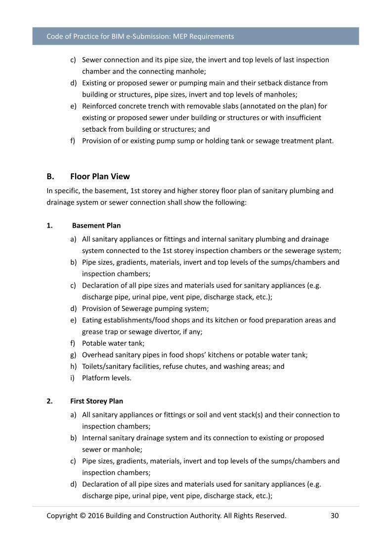
c) Sewer connection and its pipe size, the invert and top levels of last inspection
chamber and the connecting manhole;
d) Existing or proposed sewer or pumping main and their setback distance from
building or structures, pipe sizes, invert and top levels of manholes;
e) Reinforced concrete trench with removable slabs (annotated on the plan) for
existing or proposed sewer under building or structures or with insufficient
setback from building or structures; and
f) Provision of or existing pump sump or holding tank or sewage treatment plant.
B. Floor Plan View
In specific, the basement, 1st storey and higher storey floor plan of sanitary plumbing and
drainage system or sewer connection shall show the following:
1. Basement Plan
a) All sanitary appliances or fittings and internal sanitary plumbing and drainage
system connected to the 1st storey inspection chambers or the sewerage system;
b) Pipe sizes, gradients, materials, invert and top levels of the sumps/chambers and
inspection chambers;
c) Declaration of all pipe sizes and materials used for sanitary appliances (e.g.
discharge pipe, urinal pipe, vent pipe, discharge stack, etc.);
d) Provision of Sewerage pumping system;
e) Eating establishments/food shops and its kitchen or food preparation areas and
grease trap or sewage divertor, if any;
f) Potable water tank;
g) Overhead sanitary pipes in food shops’ kitchens or potable water tank;
h) Toilets/sanitary facilities, refuse chutes, and washing areas; and
i) Platform levels.
2. First Storey Plan
a) All sanitary appliances or fittings or soil and vent stack(s) and their connection to
inspection chambers;
b) Internal sanitary drainage system and its connection to existing or proposed
sewer or manhole;
c) Pipe sizes, gradients, materials, invert and top levels of the sumps/chambers and
inspection chambers;
d) Declaration of all pipe sizes and materials used for sanitary appliances (e.g.
discharge pipe, urinal pipe, vent pipe, discharge stack, etc.);

Code of Practice for BIM e-Submission: MEP Requirements
Copyright © 2016 Building and Construction Authority. All Rights Reserved. 31
e) Double floor slab (including access opening) for sanitary pipes sited over
bedroom, living room, dining room and kitchen area;
f) Reinforced concrete trench with removable slabs (annotated on the plan with
width and length dimension) for existing or proposed sewer under building or
structures or with insufficient setback from building or structures;
g) Existing & proposed sewer or pumping main and their sizes, setback from building
or structure;
h) Invert and top levels of all the manholes including the connecting manhole(s);
i) Adjacent lot and existing sewer/sanitary drainlines from adjacent lots,
j) Provision of pump sump or holding tank or sewage treatment plant.
k) Eating establishments/food shops and its kitchen or food preparation areas and
grease trap or sewage divertor, if any;
l) Potable water tank;
m) Overhead sanitary pipes in food shops’ kitchens or potable water tank;
n) Toilets/sanitary facilities refuse chutes/bin centres, and washing areas;
o) Existing sanitary drainlines that would be retained;
p) Proposed ramp, boundary fence or walls;
q) Length of branch drainline from WC to the Inspection Chamber; and
r) Platform levels.
3. Second Storey to Highest Storey Plan
a) All sanitary appliances or fittings or soil and vent stack(s) and internal sanitary
plumbing and drainage system;
b) Eating establishments/food shops and its kitchen or food preparation areas and
grease trap or sewage divertor, if any;
c) Overhead sanitary pipes in food shops’ kitchens or potable water tank;
d) Toilets/sanitary facilities, refuse chutes/bin centres and washing areas;
e) Length of WC’s discharge pipe to the discharge stack; and
f) Double floor slab (including access opening) for sanitary pipes sited over
bedroom, living room, dining room and kitchen area.

Code of Practice for BIM e-Submission: MEP Requirements
Copyright © 2016 Building and Construction Authority. All Rights Reserved. 32
C. Roof Plan View
In specific, the roof plan of sanitary plumbing and drainage system or sewer connection shall
show the following:
a) Termination of sanitary ventilation stacks;
b) Roof garden and window openings of penthouse units (indicated with distance
from the ventilation stack to the window opening); and
c) Potable water tank, if any.
D. Schematic Diagram for Sanitary Plumbing and Drainage system
In specific, the schematic diagram of sanitary works shall show all the sanitary plumbing and
drainage system in the premises.
E. Elevation View
In specific, the elevation view of sanitary plumbing and drainage system or sewer connection
shall show the following:
a) Sanitary plumbing and drainage system within the premises connected to the
sewerage system;
b) Sewer connection and its pipe size, the last inspection chamber and the
connecting manhole;
c) Pipe size and invert or top levels of existing or proposed sewer or pumping main,
and the setback distance from building or structures;
d) Reinforced concrete trench with removable slabs (with width and depth
dimension);
e) Pump sump, sewage ejector tank, holding tank or sewage treatment plant.
f) Building height;
g) Sewer setback from building or structures; horizontal and vertical clearance
distances between the building or structure/substructure and the sewers or
pumping mains;
h) Headroom for overhanging structures or roof eaves above existing or proposed
sewer or pumping main;
i) Proposed ramp, boundary fence or walls;
j) Potable water tank; and
k) Height of stack terminated on roof/roof garden.

Code of Practice for BIM e-Submission: MEP Requirements
Copyright © 2016 Building and Construction Authority. All Rights Reserved. 33
5.3. As-built Plan for TOP/CSC – Sanitary Works (Sanitary Plumbing & Drainage System/ Sewer Connection)
A. Site Plan View
In specific, all key plan and site plan of TOP/CSC sanitary works with deviations shall show the
following:
1. Key Plan
a) Boundary of development site shall be edged RED; and
b) Outline of neighbouring development plots or buildings within 1km radius shall
be shown.
2. Site Plan
a) Layout of the site with boundary lines verged in RED;
b) Outline of building or structure;
c) Sewer connection and its pipe size, material, the invert and top levels of last
inspection chambers and the connecting manhole;
d) Existing sewer or pumping main and their setback distance from building or
structures; pipe sizes, invert and top levels of manholes including the connecting
manholes;
e) Sewer and Manhole ID for existing sewer/pumping main;
f) Abandoned sewers/pumping mains;
g) Reinforced concrete trench with removable slabs (annotated on the plan) for
existing or proposed sewer under building or structures or with insufficient
setback from building or structures;
h) New sewer or diversion and their setback from building or structure, adjacent lot,
Drainage Reserve, and Road Reserve;
i) Provision of pump sump or holding tank or sewage treatment plant; and
j) Party maintaining.

Code of Practice for BIM e-Submission: MEP Requirements
Copyright © 2016 Building and Construction Authority. All Rights Reserved. 34
B. Floor Plan View
In specific, the basement, 1st storey and higher storey floor plan of TOP/CSC sanitary works
with deviations shall show the following:
1. Basement Plan
a) All sanitary appliances or fittings and internal sanitary plumbing and drainage
system connected to the 1st storey inspection chambers or the sewerage system;
b) Pipe sizes, gradients, materials, invert and top levels of the sumps/chambers and
inspection chambers;
c) Toilets/sanitary facilities, refuse chute chambers, car washing bays and garage
gully;
d) Sewerage pumping system;
e) Platform levels;
f) Eating establishments/food shops and its kitchen or food preparation areas and
grease trap or sewage divertor, if any;
g) Potable water tank (if any); and
h) Overhead sanitary pipes in food shops’ kitchens or potable water tank.
2. First Storey Plan
a) Platform levels;
b) All sanitary plumbing and drainage system and their pipe size, gradients, materials
within the premises connected to the sewerage system, sewer connection and its
pipe size, the top and invert levels of all inspection chambers and the connecting
manhole, invert levels of backdrop connection pipes to inspection
chamber/manhole;
c) All sanitary appliances or fittings or sanitary plumbing system (soil and vent
stacks) and their connection lines to inspection chambers;
d) Declaration of all pipe sizes and materials used for sanitary appliances (e.g.
discharge pipe, urinal pipe, vent pipe, discharge stack, etc.);
e) Double floor slab (including access opening) for sanitary pipes sited over
bedroom, living room, dining room and kitchen area;
f) Sanitary facilities or toilets; refuse chutes/bin centres and washing areas;
g) All existing or new sewers, diversion sewers or pumping mains and their sizes,
gradients, and setback distances from building or structures; Invert and top levels
of all the manholes including the connecting manhole(s); Adjacent lots and
sewer/sanitary connection lines from adjacent lots, Drainage Reserve and Road
Reserve;
h) Sewer and Manhole ID for existing sewer/pumping main;

Code of Practice for BIM e-Submission: MEP Requirements
Copyright © 2016 Building and Construction Authority. All Rights Reserved. 35
i) Reinforced concrete trench with removable slabs (annotated on the plan with
width and length dimension) for existing or proposed sewer under building or
structures or with insufficient setback from building or structures;
j) Eating establishments/food shops and its kitchen or food preparation areas and
grease trap or sewage divertor, if any;
k) Potable water tank;
l) Overhead sanitary pipes in food shops’ kitchens or potable water tank;
m) Provision of pump sump or holding tank or sewage treatment plant;
n) New ramp, boundary fence or walls; and
o) Length of branch drainline to the Inspection Chamber.
3. Second Storey to Highest Storey Plan
a) All sanitary appliances and fittings, soil and vent stacks and sanitary plumbing and
drainage system connected to the inspection chambers and sewerage system at
1st storey;
b) Double floor slab (including access opening) for sanitary pipes sited over
bedroom, living room, dining room and kitchen area;
c) Sanitary facilities or toilets, washing areas;
d) Eating establishments/food shops and its kitchen or food preparation areas and
grease trap, if any;
e) Overhead sanitary pipes in food shops’ kitchens or potable water tank; and
f) Length of WC’s discharge pipe to the discharge stack.
C. Roof Plan View
In specific, the roof plan of TOP/CSC sanitary works with deviations shall show the following:
a) Sanitary pipes and potable water tank; and
b) Termination of Vent stacks, roof garden and window openings of penthouse units
(with dimension from the vent stack to the opening of window).
D. Schematic Diagram for Sanitary Plumbing and Drainage system
In specific, the schematic diagram of TOP/CSC sanitary works with deviations shall show all
the sanitary plumbing and drainage system in the premises.

Code of Practice for BIM e-Submission: MEP Requirements
Copyright © 2016 Building and Construction Authority. All Rights Reserved. 36
E. Elevation View
In specific, the elevation view of TOP/CSC sanitary works with deviation shall show the
following:
a) All sanitary appliances or fittings, soil and vent stacks and the sanitary plumbing
and drainage system within the premises connected to the sewerage system;
b) Double floor slab for sanitary pipes sited over bedroom, living room, dining room
and kitchen area;
c) Sewer connection and its pipe size, the last inspection chamber and the
connecting manhole;
d) Platform levels;
e) Existing or Proposed sewer or pumping main, pipe sizes, gradients, and horizontal
and vertical clearance distances between the building or structure/substructure
and the sewers or pumping mains;
f) Building height; headroom for overhanging structures or roof eaves above
existing or proposed sewer or pumping main;
g) Reinforced concrete trench with removable slabs;
h) Pump sump or holding tank or sewage treatment plant;
i) Proposed ramp, boundary fence or walls;
j) Potable water tank (if any); and
k) Height of vertical stack terminated on roof / roof garden.
F. Summary tables indicating the numbers of the sanitary appliances (water closets, urinals, bidets and slop sinks) installed at each units in the premises or lots of the development

Code of Practice for BIM e-Submission: MEP Requirements
Copyright © 2016 Building and Construction Authority. All Rights Reserved. 37
PUBLIC UTILITIES BOARD
(PUB)
Code of Practice for BIM e-Submission: MEP Requirements
Copyright © 2016 Building and Construction Authority. All Rights Reserved. 38
6 PUB - WATER SUPPLY (NETWORK) SUBMISSION REQUIREMENT (PUB-WTR SUBMISSIONS)
6.1 General Requirements
The documents to be submitted to PUB-WTR shall meet the requirements specified under the
Singapore Standard CP48 – Code of Practice for Water Services and Public Utilities (Water
Supply) Regulations.
Only schematic line diagram and 3D cross sectional model of important parts/zones, as
specified below, are required for PUB-WTR BIM e-submission. No 2D floor plans, elevations
and sectional drawing views are required during submission.
PUB-WTR Submission Documents
2D View Part 3D BIM Model
Site and location plan
Schematic drawing
Notes and legend page
Typical detail
Water tanks
PUB meter chambers
PUB submeter compartments
6.2 2D Views
A. Site and Location Plan
Site and location plan shall including the following details:
a) Proposed water meter location;
b) Entrance to development; and
c) Boundary of development sites.

Code of Practice for BIM e-Submission: MEP Requirements
Copyright © 2016 Building and Construction Authority. All Rights Reserved. 39
Fig. 9 - Example: Site and Location Plan
Image credit to AECOM

Code of Practice for BIM e-Submission: MEP Requirements
Copyright © 2016 Building and Construction Authority. All Rights Reserved. 40
B. Schematic Drawing
Overall water system schematic drawing shall indicate the following:
a) Proper labeling to be provided for the various water pipes;
b) Reduced level of every floor;
c) Reduced level of highest water fitting (including flush valve), fire hydrant and fire
hose reel (if applicable) receiving direct supply from PUB water mains;
d) Diameter of all water pipes;
e) Terminal water draw-off fittings;
f) Breakdown of estimated daily direct and indirect water requirements;
g) Water tank including the following details:
i. Inlet, outlet, overflow, warning and drain pipes with their diameters;
ii. Reduced level of inlet to tank;
iii. Material of tank;
iv. Nominal size and effective capacity of tank; and
v. Enclosure/Room for the tank.
h) PUB water/NEWater meters and chambers – For meter size 25 mm and above
i. Plan view
o Meter spacing;
o Width of chamber; and
o Valve assemblies downstream of water meter leading to the respective
systems (e.g. domestic, fire hydrant, fire sprinklers, etc.).
ii. Elevation view
o Height of chamber;
o Chamber cover details; and
o Drainage.
i) PUB Water meter for landed properties (for 15mm meter)
i. Elevation view
o Meter spacing;
o Position in gate pillar; and
o Height of enclosure.

Code of Practice for BIM e-Submission: MEP Requirements
Copyright © 2016 Building and Construction Authority. All Rights Reserved. 41
j) PUB water submeter compartment (if applicable)
i. Plan view
o Distance from submeter to the door of compartment;
o Clearance between submeter and side wall of compartment; and
o Position of door of compartment.
ii. Elevation view
o Meter spacing;
o Spacing between PUB submeters;
o Drainage; and
o Height of submeter from the ground.

Code of Practice for BIM e-Submission: MEP Requirements
Copyright © 2016 Building and Construction Authority. All Rights Reserved. 42
Fig. 10 - Example: Schematic drawing for PUB WTR submission
Image credit to Rankine&Hill

Code of Practice for BIM e-Submission: MEP Requirements
Copyright © 2016 Building and Construction Authority. All Rights Reserved. 43
6.3. Part 3D BIM Model
The following part 3D BIM models maybe submitted:
a) Water tank details with surrounding fencing/enclosure;
b) PUB water and NEWater meter connection details and the meter chamber; and
c) PUB sub-meter connection details and compartment details.
Fig. 11 - Example: Water Tank Details
Fig. 12 - Example: Bulk Meter Connection
Image credit to Rankine&Hill

Code of Practice for BIM e-Submission: MEP Requirements
Copyright © 2016 Building and Construction Authority. All Rights Reserved. 44
SINGAPORE CIVIL
DEFENCE FORCE
(SCDF)

Code of Practice for BIM e-Submission: MEP Requirements
Copyright © 2016 Building and Construction Authority. All Rights Reserved. 45
7 SCDF FIRE SAFETY AND SHELTER DEPARTMENT (FSSD) REQUIREMENTS
7.1 General Requirements for All FSSD Submissions
The documents submitted under section 23 (1) of the Fire Safety Act shall consist of a location
plan, a site plan, a floor plan of each storey, a roof plan of the building and sectional and
elevation drawing of the building. All dimension and grid shall be indicated clearly on plans.
FSSD Submission Documents
2D View BIM Model
Site and location plan
Notes and legend page
Schematic drawing
Floor plans generated from BIM
model
Part 3D BIM Model
7.2 2D Views
A. Site and Location Plan
1. Location Plan
a) The coloured location of the lot relative to neighbouring lots; and
b) The various roads constituting the access layout to the lot.
2. Site Plan
a) The means of access to the site and to the perimeter of each building for fire
fighting vehicles and equipment;
b) Distances between each building or fire safety works and the relevant lot
boundaries, other proposed or existing buildings or installations on the site;
c) The location of existing and proposed internal fire-hydrants on the site; and
d) Any other feature on or in the vicinity of the site which is likely to be a fire hazard
or is likely to cause obstruction to fire fighting vehicles and equipment and rescue
operations.

Code of Practice for BIM e-Submission: MEP Requirements
Copyright © 2016 Building and Construction Authority. All Rights Reserved. 46
B. Schematic Diagram
A schematic diagram of the overall system(air-conditioning, mechanical ventilation or fire
protection) showing clearly the key features and their functions, relative locations in the
building, lots, sizes, capacities and other essential information including the air distribution
design arrangement in the case of air-conditioning and mechanical ventilation systems.
7.3 Floor Plan generated from BIM Model and BIM Models
A. Floor Plan generated from BIM Model
Plans to be submitted for air-conditioning, mechanical ventilation and fire protection works
shall include the following:
a) Key features of the building in which the system is to be installed the particulars
listed in Fire Safety (Building and Pipelines Fire Safety) regulations 6 and 7;
b) The layout of the system on every floor plan showing clearly the various parts and
their functions, locations, arrangements, sizes, capacities and other essential
information;
c) Necessary cross-sectional views as superimposed on the building or part thereof
to fully describe the details and configurations of the system;
d) For air-conditioning and mechanical ventilation systems such additional details as:
i. The volumetric rate of flow of air at each point of inlet and outlet of each
system including those serving protected staircases, exit passageways,
lobbies, areas of refuge, the Fire Command Centre, fire pump rooms,
generator rooms, rooms used for the storage of flammable liquids or gas or
other areas of special risk;
ii. The location of fire compartment walls, floors and air shafts;
iii. The location of fire dampers;
iv. The location of smoke detectors; and
v. The location and function of other fire precautionary features.

Code of Practice for BIM e-Submission: MEP Requirements
Copyright © 2016 Building and Construction Authority. All Rights Reserved. 47
B. BIM Model
QP shall prepare the important part 3D model, in accordance to section 7.3 of this chapter,
for submission. The part 3D BIM Model shall show the following clearly specified below:
1. ACMV System Checklist
1 Indicate the fire rating, capacity and dimensions of the ducts.
2 Indicate the location of compartment walls/floors, air shafts and location of
fire dampers.
3 Indicate the location and volumetric rate of flow of air at each point of inlet
and outlet of each system including those serving protected staircases, exit
passageways, lobbies, areas of refuge, the Fire Command Centre, fire pump
rooms, generator rooms, rooms used for the storage of flammable liquids or
gas or other areas of special risk.
4 Indicate the routing of ducts.
5 Indicate then location of intake and exhaust of MV system
6 Indicate the types of ventilation duct. E.g. Kitchen exhaust, fresh air duct, duct
for smoke control system.
7 Provide the necessary cross-sectional views as superimposed on the building
or part thereof to fully describe the details and configurations of the system.
Fig. 13 - Example: Part 3D Model
Image credit to Surbana Jurong

Code of Practice for BIM e-Submission: MEP Requirements
Copyright © 2016 Building and Construction Authority. All Rights Reserved. 48
2. Sprinkler System Checklist
1 Indicate the sprinkler tank capacity and material of construction
2 Indicate the location of sprinkler tank
3 Indicate the location of standby generator and compartmentation.*
4 Indicate the highest point / most remote point of the sprinkler head
5 Indicate the location of sprinkler control valve & pump
6 Show the height of highest sprinkler above the control valve & pump
7 Indicate the pipe size and orifice size
8 Indicate the discharge density and temperature of sprinkler head
9 Indicate the design hazard group
10 Indicate the coverage per sprinkler head and area of operations
11 Indicate the Routing of sprinkler pipes
12 Provide the necessary cross-sectional views as superimposed on the building
or part thereof to fully describe the details and configurations of the system
*Architectural consultant to provide info.

Code of Practice for BIM e-Submission: MEP Requirements
Copyright © 2016 Building and Construction Authority. All Rights Reserved. 49
Fig. 14 - Example: Sprinkler Tank
Image credit to Surbana Jurong

Code of Practice for BIM e-Submission: MEP Requirements
Copyright © 2016 Building and Construction Authority. All Rights Reserved. 50
3. Detectors Checklist
S/N Items Compliance
Yes No NA
1 Type of detector
2 Schematic diagram
Image credit to Surbana Jurong
3 Zoning
Image credit to Surbana Jurong

Code of Practice for BIM e-Submission: MEP Requirements
Copyright © 2016 Building and Construction Authority. All Rights Reserved. 51
4 Coverage and number detector within the zone
Image credit to Surbana Jurong
5 Location of alarm panels Visual check

Code of Practice for BIM e-Submission: MEP Requirements
Copyright © 2016 Building and Construction Authority. All Rights Reserved. 52
CORE INFORMATION FOR BIM OBJECTS
This section describes the essential non-geometry properties/attributes of the model objects
that shall be provided for regulatory/technical agencies submission.
The BIM object shall contain minimum non-geometry information for technical agencies
submission as following:
FSSD - Sprinkler System
Sprinklers
Pendent Upright Sidewall
Parameter Name Sample Value Temperature Rating 68 °C
Sprinkler Type Concealed/Exposed K factor 8
Hazard Group Ordinary/High Hazard
Fire Hose Reel
Fire Hose Reel with Cabinet Fire Hose Reel
Parameter Name Sample Value Design Pressure 6 Bars
Design Flow Rate L/s Breeching Inlet
4 Way Breeching Inlet 2 Way Breeching Inlet

Code of Practice for BIM e-Submission: MEP Requirements
Copyright © 2016 Building and Construction Authority. All Rights Reserved. 53
Parameter Name Sample Value Design Pressure 6 Bars
Design Flow Rate L/s
Fire Hydrant
Parameter Name Sample Value Design Pressure 6 Bars
Design Flow Rate L/s
Fire Sprinkler Pump
Parameter Name Sample Value Pump Flow rate 25 l/s
Pump Head 50m
Sprinkler Tank

Code of Practice for BIM e-Submission: MEP Requirements
Copyright © 2016 Building and Construction Authority. All Rights Reserved. 54
Parameter Name Sample Value Length 4m Width 3m Height 3m
Effective Volume 21.6m3 Effective Height 1.8m Tank Material Pressed steel
FSSD - ACMV
Fire Damper
Parameter Name Sample Value Hour Rating 2 hrs
Air Terminal

Code of Practice for BIM e-Submission: MEP Requirements
Copyright © 2016 Building and Construction Authority. All Rights Reserved. 55
Parameter Name Sample Value Design Air Flow 175 CMH
Mechanical Fans
Parameter Name Sample Value Design Air Flow 300 CMH Static Pressure 250 Pa
Emergency Source Yes/No

Code of Practice for BIM e-Submission: MEP Requirements
Copyright © 2016 Building and Construction Authority. All Rights Reserved. 56
FSSD - Detectors
Detectors
Parameter Name Sample Value Detector Type Smoke/Heat
PUB Water & CBPD Sanitary
Sprinkler Tank
Parameter Name Sample Value Length 4m Width 3m Height 3m
Effective Volume 21.6m3 Effective Height 1.8m Tank Material Pressed steel
Fire Sprinkler Pump

Code of Practice for BIM e-Submission: MEP Requirements
Copyright © 2016 Building and Construction Authority. All Rights Reserved. 57
Parameter Name Sample Value Pump Flow rate 10 L/s
Pump Head 25 m Emergency Power Source Yes/No
Inspection Chamber/ Silt Trap
Parameter Name Sample Value
Top Level 110.300 mm Invert Level 109.550 mm
Depth 0.750 mm
CITYGAS
Pipe and Pipe Fittings (includes elbows, tees, unions and etc.)

Code of Practice for BIM e-Submission: MEP Requirements
Copyright © 2016 Building and Construction Authority. All Rights Reserved. 58
2D View
3D View
2D view requirements 3D view requirements Plans shall show the specifications of gas
installation such as dimensions, pipe material, ventilation arrangement including routing & pipe sleeve/ducting, pipe location etc. as required under the Regulations and
Codes.
3D model view is for better visualization of the gas installation. Process of gas
installation is based on 2D model view
Gas Pipe Box-up
Parameter Name Sample value
Type Fire Rated
Gas Pipe Sleeve
Parameter Name Sample value Material Stainless Steel

Code of Practice for BIM e-Submission: MEP Requirements
Copyright © 2016 Building and Construction Authority. All Rights Reserved. 59
COLOUR STANDARDS
This section describes the standard colours to adopt for MEP regulatory submission.
a. Air-Conditioning & Mechanical Ventilation System
System Colour Red Green Blue
Supply Air System* 5 0 0 255
Return Air System* 6 255 0 255
Fresh Air System* 3 0 255 0
Exhaust Air System* 54 153 153 0
Kitchen Supply Air System* 91 127 255 127
Kitchen Exhaust Air System* 53 204 204 102
Staircase Pressurization Air System* 71 191 255 127
Toilet Exhaust Air System* 55 153 153 76
Fire rated duct hatching 14 153 0 0
Fire Damper 1 225 0 0
Thermostat 94 0 153 0
* System includes all connected ducts, grilles, diffusers, fittings, accessories, equipment etc.

Code of Practice for BIM e-Submission: MEP Requirements
Copyright © 2016 Building and Construction Authority. All Rights Reserved. 60
b. Plumbing and Sanitary System
System Colour Red Green Blue
Domestic cold water supply system* 5 0 0 255
Domestic hot water supply system* 0 0 0
NEWater pipe 214 153 0 153
Vent pipe system* 3 0 255 0
Sanitary discharge system* 1 255 0 0
Inspection chamber, waste sump 14 153 0 0
* System includes all connected pipes, fittings, accessories, equipment etc.
c. Fire Protection System
System Colour Red Green Blue
Fire sprinkler system* 1 255 0 0
Wet riser system* 1 255 0 0
Fire alarm system* (exclude call point) 14 153 0 0
Emergency voice communication system * 14 153 0 0
Dry riser system* (Submission for reference) 0 0 0
Hose reel system* (Submission for reference) 0 0 0
Fire hydrant system* (Submission for reference) 0 0 0
* System includes all connected pipes, fittings, accessories etc.

Code of Practice for BIM e-Submission: MEP Requirements
Copyright © 2016 Building and Construction Authority. All Rights Reserved. 61
d. Gas System
System Colour Red Green Blue
Gas system* 1 255 0 0
Gas ventilation duct 3 0 255 0
* System includes all connected pipes, fittings, accessories etc.

Code of Practice for BIM e-Submission: MEP Requirements
Copyright © 2016 Building and Construction Authority. All Rights Reserved. 62
SUBMISSION FORMAT SUMMARY
Technical agencies 1st submission Amendment submission
As-built submission
PUB - WTR light-weight - light-weight
BCA - TSED native native native
BCA - CDSD native native native
IDA-TFCC native native -
CityGas light-weight light-weight light-weight
SCDF
FPS
ACMV
Detector
light-weight light-weight -
NEA-CBPD & PUB- WRN
light-weight light-weight dwg – for 1st storey light-weight native
* The respective regulatory agency reserves the right to request BIM native file for verification.
LIST OT FIGURES
Fig. 1 - Example: Site Plan
Fig. 2 - Example: Schematic Diagram
Fig. 3 - Example: Plans generated from BIM Model
Fig. 4 - Example: Part 3D BIM Model
Fig. 5 - Example: Site Plan
Fig. 6 - Example: Location Plan
Fig. 7 - Example: Schematic Drawing
Fig. 8 - Example: Part 3D MDF Room with lead in pipe
Fig. 9 - Example: Site and Location Plan
Fig. 10 - Example: Schematic drawing for PUB WTR submission
Fig. 11 - Example: Water Tank Details
Fig. 12 - Example: Bulk Meter Connection
Fig. 13 - Example: Part 3D Model
Fig. 14 - Example: Sprinkler Tank

Code of Practice for BIM e-Submission: MEP Requirements
Copyright © 2016 Building and Construction Authority. All Rights Reserved. 63
CODE OF PRACTICE FOR BIM E-SUBMISSION SERIES
This section is part of the Code for Practice for BIM e-Submission series:
Code of Practice for BIM e-Submission
A. General Requirements
B. Architectural Requirements
C. Civil & Structural (C&S) Requirements
D. Mechanical, Electrical & Plumbing (MEP) Requirements
Building and Construction Authority 52 Jurong Gateway Road #11-01, Singapore 608550 www.bca.gov.sg
For more information and feedback on the Code of Practice for
Building Information Modelling series, please visit the CORENET website:
www.corenet.gov.sg
All documents related to BIM e-Submission can be downloaded from the CORENET
website:
o Code of Practice for BIM e-Submission
o BIM e-Submission Templates
o BIM e-Submission Template Guides
https://www.corenet.gov.sg/general/building-information-modeling-(bim)-e-
submission.aspx