October 2014 - Power Transmission Engineering
60
OUTDATED ELECTRIC MOTORS Still Prevalent Servo Technology Quandary: To Centralize or Decentralize? Electric Vehicle Motors’ Noisy Gears MADE IN CHINA A First-Hand Perspective OCTOBER 2014 www.powertransmission.com ® Chariots to E-Fans: The Next Way Around Just Waiting to Be Invented Power Play [ Ask the Expert: Bearing Basics ] [ Premature Bearing Failures in Wind Gearboxes and White Etching Cracks ] Technical
-
Upload
vuongkhanh -
Category
Documents
-
view
215 -
download
0
Transcript of October 2014 - Power Transmission Engineering

OUTDATED ELECTRICMOTORS Still Prevalent
Servo Technology Quandary: To Centralize or Decentralize?
Electric Vehicle Motors’ Noisy Gears
MADE IN CHINAA First-Hand Perspective
OCTOBER 2014
www.powertransmission.com
®
Chariots to E-Fans: The Next Way Around Just Waiting to Be Invented
Power Play
[ Ask the Expert: Bearing Basics ]
[ Premature Bearing Failures in Wind Gearboxes and White Etching Cracks ]
Technical

the #1 value in automationOrder Today, Ships Today!
* See our Web site for details and restrictions. © Copyright 2014 AutomationDirect, Cumming, GA USA. All rights reserved. 1-800-633-0405
General purpose AC motors
IRONHORSE motors are availablein rolled steel (1/3 to 2 hp) and castiron (1 to 300 hp) 1800 RPM models.Selected 1200 and 3600 RPM unitsfor the most popular horsepowerratings start at just $70. And Premi-um E� ciency models meet current NEMA standards from 1 to 150 hp, starting at $155.
• T-frame cast iron three-phase,208-230/460V up to 300 hp,TEFC enclosure
• 56C frame rolled steel single-phase,115/208-230V, from 0.33 to 1.5 hp,TEFC enclosure
• 56C frame rolled steel three-phase,208-230/460V, from 0.33 to 2 hp,TEFC enclosure
• TC frame (C-face) cast iron three-phase,208-230/460V, up to 100 hp,TEFC enclosure
Inverter-duty AC motors
MARATHON ELECTRIC inverter-dutymotors have been carefully selectedto be performance-matched with ourDURApulse and GS series AC drives.
• 1/4 to 100 hp
• Dual 230/460V and 575 VAC models
• 1200 and 1800 RPM base speeds
• Factory-mounted encoders onselect models
• NEMA Premium Effi ciency XRI seriesfrom 1 to 10 hp compliant with EnergyIndependence and Security Act of2007
DC motors and gearmotors
IRONHORSE PMDC motors are available in TENV and TEFC rolled steel enclosure styles. Space-saving designs feature a NEMA 56C � ange and remov-able mounting base.
• 0.33 to 2 hp, 1800 RPM
• Electrically reversible
• Compatible with SCR (thyristor)DC drives
• 90VDC and 180VDC models available
Small DC motors are now available from 1/31 hp; DC gearmotors can be used with variable speed drives or in across-the-line applications, in parallel (from 1/17 hp) and right-angle (from 1/19 hp) styles that start at just $146.
CHECK OUT OUR PRICES ON MOTORS
AC, 208-230/460V,3-phase, TEFC,1800 rpm, 1 hp
PMDC, 56C,2 hp, 180V
$125.00MTR-001-3BD18
AutomationDirectIronHorse
Baldor
$372.00MTPM-002-1M18
All prices are U.S. published prices. AutomationDirect prices are from October 2014 Price List. Baldor prices taken from www.baldor.com 2/20/2014. Daytonprices taken from www.grainger.com 2/20/2014. Prices and specifications may vary by dealer and configuration. Prices subject to change without notice.
$476.00CM3546
$2,662.00CDP3585
$302.254THX2
Dayton
$1,580.004Z380 (not 56C)
Research, price, buy at:www.automationdirect.com/motors
56C GearboxesMotor Bases(56 - 449T)
Also AvailableAlso Available
1410-PowerTransmissionEngineering-Motors-MAG.indd 1 9/25/14 12:55 PM

[32] Ask The ExpertBearing basics.
[34] Premature Bearing Failure in Wind Gearboxes and White Etching Cracks
How to make bearings more robust.
[18] Outdated Motor/Gear Systems Still Prevalent
Electric motor-driven systems account for over 40% of global consumption, according to the International Energy Agency.
[24] Servo Technology: Centralized or Decentralized?
Which architecture type delivers the best technical and commercial advantages?
[30] Electric Vehicles Need Quieter Gears
But the gears may not be the problem!
[41] Made in ChinaA GM Engineer's First-Hand Perspective on the Chinese Roller Bearing Industry.
FEATURE ARTICLES TECHNICAL ARTICLES
Vol. 8, No. 7. POWER TRANSMISSION ENGINEERING (ISSN 2331-2483) is published monthly except in January, May, July and November by Randall Publications LLC, 1840 Jarvis Ave., Elk Grove Village, IL 60007, (847) 437-6604. Cover price $7.00. U.S. Application to Mail at Periodicals Postage Prices is Pending at Palatine, IL and at additional mailing offices. Send address changes to POWER TRANSMISSION ENGINEERING, 1840 Jarvis Ave., Elk Grove Village, IL 60007.
Randall Publications LLC makes every effort to ensure that the processes described in POWER TRANSMISSION ENGINEERING conform to sound engineering practice. Neither the authors nor the publisher can be held responsible for injuries sustained while following the procedures described. Postmaster: Send address changes to POWER TRANSMISSION ENGINEERING, 1840 Jarvis Avenue, Elk Grove Village, IL, 60007. ©2014 Contents copyrighted by RANDALL PUBLICATIONS, LLC. No part of this publication may be reproduced or transmitted in any form or by any means, electronic or mechanical, including photocopying, recording, or by any information storage and retrieval system, without permission in writing from the publisher. Contents of ads are subject to Publisher’s approval.
OCTOBER 2014
®
1Power Transmission EngineeringOCTOBER 2014
[24]
CONTENTS
[41]
[18]

VOL. 8, NO. 7
[04] PTExtrasA little of this, some of that
[06] EditorialMade in USA, Sourced in China
[08] Product NewsNewest hardware, software, etc.
[46] Industry NewsNew prez named at Circle Gear; othernews of note
[52] CalendarOctober 27–30: Gear Dynamics and Gear Noise Course, Ohio State Univ.;November 2–5: Pack Expo Int’l, McCormick Place, Chicago.
[54] Advertiser IndexAdvertiser contact information
[55] SubscriptionsFree subscriptions, anywhere in the world
[56] Power PlayChariots to Steamboats to E-Fans
OUTDATED ELECTRICMOTORS Still Prevalent
Servo Technology Quandary: To Centralize or Decentralize?
Electric Vehicle Motors’ Noisy Gears
MADE IN CHINAA First-Hand Perspective
OCTOBER 2014
www.powertransmission.com
®
Chariots to E-Fans: The Next Way Around Just Waiting to Be Invented
Power Play
[ Ask the Expert: Bearing Basics ]
[ Premature Bearing Failures in Wind Gearboxes and White Etching Cracks ]
Technical
Designed to ProtectTM
Overload Release Clutches
Phone: 262.554.7500 Fax: 262.554.7503
www.cabatinc.com
abat®
A Division of A&E Incorporated
2 Power Transmission Engineering ]————WWW.POWERTRANSMISSION.COMOCTOBER 2014
CONTENTS
The Power of Knowledge Engineering
Gear up for higher reliabilitywith upgraded SKF Explorer bearingsA robust solution for harsh and demanding gearbox environments, upgraded SKF Explorer bearings enable a gear unit to transmit more torque, sustain higher external loads, or even be downsized to improve cost effi ciency.
In addition, these bearings provide substantially longer life than other bearings. In fact, they have up to twice the rating life of original SKF Explorer bearings, especially under contaminated and poor lubrication operating conditions.
With expertise in bearings, sealing, and lubrication solutions, SKF engineers can add value to the complete gear unit by enhancing reliability and performance, while improving the cost-effectiveness of the complete solution.
For more information, please visit skf.com or contact your local SKF representative.Enhance gear unit reliability and improve performance
Upgraded SKF Explorer self-aligning bearings have enhanced wear and contamination resistance, and are better able to run under tough conditions – up to 100% longer bearing rating life.
EDITORIALPublisher & Editor-in-Chief
Michael [email protected]
Managing Editor & Associate PublisherRandy Stott
Senior EditorJack McGuinn
Senior EditorMatthew Jaster
Editorial ConsultantPaul R. Goldstein
ARTArt Director
David [email protected]
ADVERTISINGAdvertising Sales Manager
& Associate PublisherDave Friedman
China Sales AgentEric Wu
Eastco Industry Co., Ltd.Tel: (86)(21) 52305107Fax: (86)(21) 52305106Cell: (86) [email protected]
Materials CoordinatorDorothy Fiandaca
DIGITALContent ManagerKirk Sturgulewski
CIRCULATIONCirculation Manager
Carol [email protected]
RANDALL PUBLICATIONS STAFFPresident
Michael Goldstein
AccountingLuann Harrold
Randall Publications LLC1840 Jarvis Avenue
Elk Grove Village, IL 60007Phone: (847) 437-6604
Fax: (847) 437-6618
Stay Connected with Social Media
Follow us on Twittertwitter.com/#!/PowerTransMag
Connect with us on LinkedInwww.linkedin.com/groups/Power-Transmission-Engineering-PTE-2950055
Subscribe Onlinewww.powertransmission.com/subscribe.htm
PTE VideosAST Bearing Failure AnalysisWhat went wrong and why? Watch an original AST video on bearing failure analysis to see how experts determine why a bearing failed prematurely and reconstruct the sequence of events leading up to the problem. Online now at www.powertransmission.com.
Detailed Gear Design – Beyond Simple Service FactorsLearn more about this upcoming seminar (November 5-7 in Las Vegas) and other upcoming industry events by visiting www.powertransmission.com/events.htm.
Step-Flex Shaft Coupling for Stepper MotorsThis coupling was designed specifically to combat vibration and resonance in stepper and servo motors applications. The Step-Flex features an innovative combination of an HNBR (black) rubber element flanked by smaller, softer laminated (green) spacers. This unique design quickly dampens oscillations, thereby suppressing resonance phenomena. This also eliminates the need for feedback loop controls. The machined aluminum hubs offer a low moment of inertia, and are available in clamp style bores. See a video of this coupling in action at www.powertransmission.com.
Buyers Guide – Don’t Be Left OutThe deadline is October 31 to be included in the December issue’s printed buyers guide. Visit www.powertransmission.com/adinfo.htm to learn more about discounted advertising offers or visit www.powertransmission.com/getlisted.php to make sure your company’s free listing is up to date.2015 Buyers Guide of the Magazine of
Mechanical Components
®
4 Power Transmission Engineering ]————WWW.POWERTRANSMISSION.COMOCTOBER 2014
PTExtras
www.powertransmission.com

w w w . A r r o w G e a r. c o m6 3 0 . 9 6 9 . 7 6 4 0
The Precision Gear Specialists
High Quality Spiral Bevel Gears from Stock!Every day, thousands of power transmission manufacturers around the world rely on precisionstock gears produced by Arrow Gear Company.
Arrow Gear offers a full range of precision spiral bevels from stock - up to 16inches in diameter - including ground tooth gears. Featuring carburized andhardened teeth, and gears that are produced in matched sets, Arrow's stock gearsare available for immediate delivery. Arrow's stock gears can also be modified tomeet individual customer needs.
With over 65 years experience, Arrow’s stock gears are manufactured with the same processes usedfor our custom aerospace products. With a state-of-the-art production facility and dedicatedpersonnel who are among the best in the business, Arrow Gear offers the expertise and precisionfor the most demanding quality requirements.
When you need quality, expertise, and precision,you can rely on Arrow Gear!
Visit Arrow Gear’sVirtual Tour at
www.ArrowGear.com/tour
Made in the USA, Sourced in ChinaIf you read only one article this issue, it should be Norm Parker’s article on the Chinese bear-ing manufacturing industry. Parker is an engineer with General Motors, a true industry insider who has become a regular contributor to Power Transmission Engineering.
In his article, “Made in China: A GM Engineer’s First-Hand Perspective on the Chinese Roller Bearing Industry,” Parker gives us a personal account of how Chinese bearing manu-facturing has grown and changed, and why — no matter what our nationalities, patriotisms and prejudices, it’s here to stay.
Along the way, he dispels some myths and opens our eyes to just how global the industry has become. More im-portantly, as an engineer who is responsible for sourcing bearings, he explains why not all manufacturers are created equal — Chinese or otherwise — and he also explains the basics of what goes into the costs of a bearing. And no mat-ter where you buy your bearings, those cost drivers are the same. Understanding why some bearings are cheaper than others will make you a better buyer.
So read the article, which begins on page 40, because ask-ing some of the questions Parker raises will help you identify the best suppliers for your products.
Another thing that will help you identify the best suppliers is simply knowing who they are. We can help with that, and we intend to — not just for bearings, but for all types of mechani-cal power transmission and motion control products. In our next issue, we’ll produce our annual printed buyers guide.
As many of you already know, our online buyers guide is a terrific resource for finding potential suppliers of me-chanical power transmission and motion control products. More than 500 suppliers are listed, including manufactur-ers of gears, bearings, motors, clutches, couplings, brakes, belt drives and more. You can contact any of these suppliers quickly and easily by visiting www.powertransmission.com.
Our December issue brings that information right into your hands in a hard-copy that serves as a handy reference throughout the year. Whether you use the online version or the printed version, we’ve done our best to ensure that the listings are as up-to-date and accurate as possible. After all, helping engineers source components is a big part of what we do here, so we have our editors verify each listing before it’s published.
If you’re a supplier of mechanical power transmission components and you’d like to be included in both the online buyers guide and the printed buyers guide, getting listed is free. All you have to do is visit www.powertransmission.com/getlisted.php and fill out the form to tell us a little bit about your company.
As always, we’re interested in your feedback. If you have any suggestions for ways we can help engineers and other specifiers and buyers of components better understand the technology or identify potential suppliers, we’d love to hear from you. We welcome your submissions and are interested in hearing your news. Send ideas for articles, letters to the editor, random thoughts, hare-brained ideas and whatever else you’d like to get off your chest or share with the industry. You can always e-mail me at [email protected].
6 Power Transmission Engineering ]————WWW.POWERTRANSMISSION.COMOCTOBER 2014
EDITORIAL Randy Stott, Managing Editor

Machine and Gear Corporation
Toll Free: (800) [email protected] www.brgear.com
REVERSE ENGINEERING
BREAKDOWN SERVICES
SPIRAL BEVEL GEARS: 66" PDSTRAIGHT BEVEL GEARS: 80" PD
SPURS, HELICALS, SPLINE SHAFTSGEARBOX REPAIR/REBUILDS
IN-HOUSE STEEL MATERIAL WAREHOUSE
FULL HEAT TREATING SERVICES
EDM WIRE BURNING
CUSTOMBEVEL GEAR MANUFACTURING

Napoleon EngineeringANNOUNCES AEROSPACE BEARING PRODUCTS
The ISO9001:2008 and AS9100C certi-fied Napoleon Engineering Services (NES) recently announced the com-pany’s specially tailored bearing prod-ucts and services for the aerospace industry, including aircraft bearing re-engineering for Federal Aviation Ad-ministration parts manufacturing ap-proval (PMA-FAA); custom aerospace bearing manufacturing; First Article Inspection (FAI) per AS9102; and other aerospace bearing testing and bearing inspection services.
Reverse bearing engineering services for PMA-FAA Certification
One of the more comprehensive in-spection programs offered by NES is the reverse engineering of Typed Cer-tified aircraft ball and roller bearings for FAA Certification. Bearing suppli-ers which were not integrated into an aircraft at the point of original design must obtain an independent PMA from the FAA. PMA-FAA bearing reverse en-gineering is a method for ensuring that commercial aircraft replacement bear-ings can meet or exceed the same rig-orous quality, design and performance standards as those originally specified. To support these requirements, a team of highly experienced NES engineers and technicians perform a thorough physical evaluation of aircraft bear-ings, using highly specialized equip-ment and data analysis tools. The end product is an accurate and detailed analysis which provides aircraft bear-ing suppliers with all of the necessary PMA-FAA certification inspection data, as well as added assurances that its aircraft bearing manufacturing meets or exceeds supplier standards for form, fit and function.
Custom aerospace bearing manufacturing
Aerospace bearing manufacturing typically requires the use of superior quality raw materials; the incorpora-tion of extensive design and project review processes; and support for any required material or process trace-ability. To meet these needs, NES of-fers complete design, development
and manufacturing of custom high-precision aerospace ball and roller bearings, as well as custom bearing modification. The manufacturing pro-cess includes close collaboration with an aerospace OEM’s own in-house en-gineering team, with full project man-agement support from initial concept thru final delivery. Typical require-ments range from all stainless steel full complement bearings; to M50 long life angular contact ball bearings; to superelastic Ni-Ti alloy designs which incorporate wear-resistant, high-life materials and coatings. Supported ap-plications include satellite and UAV arm actuation, antennas, fuel pumps, ram air turbines, rocket engine valves, turbine engines, and rotorcraft trans-missions. Expedited lead times are available upon request.
First article inspection (FAI) per AS9102
NES offers FAI as an integral part of its aerospace bearing inspection offer-ings. FAI is used by aerospace manu-facturers to verify that a delivered bearing conforms to all engineering re-quirements. A physical and functional inspection further verifies that pre-scribed production methods have pro-duced a part or item that is acceptable with respect to engineering drawings and specifications, purchase orders,
planning documents, or other relevant design documents. Using FAI, custom-ers gain added confidence in the total conformance of first-run bearings to required end-use material, engineer-ing, and quality standards. For compa-nies requiring an FAI per AS9102, NES can provide a complete, independent, and documented FAI, with or without material specification and special pro-cess accountability.
Aerospace bearing inspection and bearing testing services
In addition to the aforementioned ca-pabilities, the Olean, New York-based NES is also home to North America’s largest independent aerospace bear-ing inspection and bearing testing fa-cility. This includes over 40 active bear-ing test rigs. In-laboratory capabilities include bearing failure analysis and metallurgical testing; bearing stress analysis, including source qualifica-tion inspection (SQI); environmental testing; RCF and dynamic life cycle testing; and impact and static load testing. In addition, NES can design and manufacture a custom aerospace bearing test rig to suit virtually any in-house requirement.
For more information:Napoleon Engineering ServicesPhone: (877) 870-3200www.nesbearings.com
8 Power Transmission Engineering ]————WWW.POWERTRANSMISSION.COMOCTOBER 2014
PRODUCT NEWS
Build it or Crush it Convey it or Dump it Pour it or Pave it Grade it or Dig it...Make sure you it!X-life products from Schaeffler feature optimized roller geometries and raceway finishes that are so precise, their service life far exceeds the conventional standard — as much as 70% in the case of our cylindrical and spherical roller bearings.
Need more details? Contact a Schaeffler design engineer at 803-396-3644 or [email protected]
©2013
Superior-quality products.Comprehensive reliable solutions.
TM
Schaeffler_PowerTransEng_Oct2014.indd 1 8/18/2014 10:37:47 AM
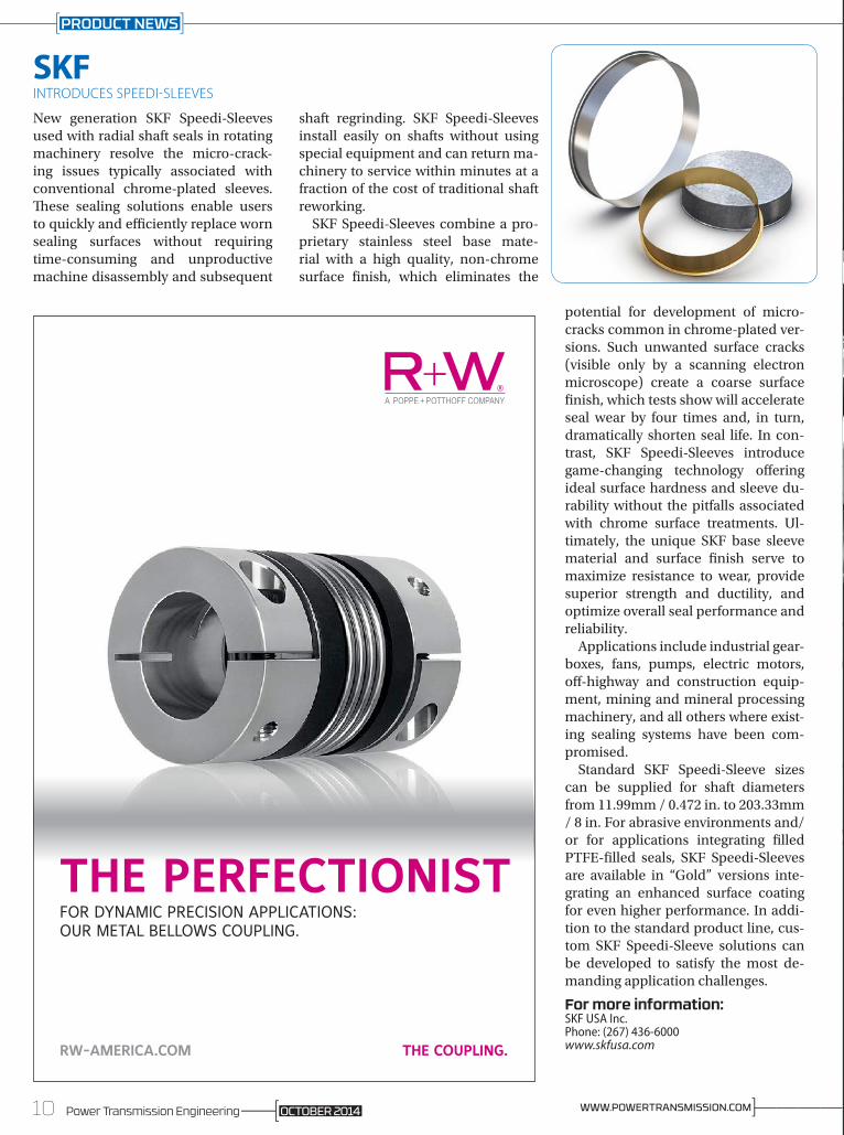
SKFINTRODUCES SPEEDI-SLEEVES
New generation SKF Speedi-Sleeves used with radial shaft seals in rotating machinery resolve the micro-crack-ing issues typically associated with conventional chrome-plated sleeves. These sealing solutions enable users to quickly and efficiently replace worn sealing surfaces without requiring time-consuming and unproductive machine disassembly and subsequent
shaft regrinding. SKF Speedi-Sleeves install easily on shafts without using special equipment and can return ma-chinery to service within minutes at a fraction of the cost of traditional shaft reworking.
SKF Speedi-Sleeves combine a pro-prietary stainless steel base mate-rial with a high quality, non-chrome surface finish, which eliminates the
potential for development of micro-cracks common in chrome-plated ver-sions. Such unwanted surface cracks (visible only by a scanning electron microscope) create a coarse surface finish, which tests show will accelerate seal wear by four times and, in turn, dramatically shorten seal life. In con-trast, SKF Speedi-Sleeves introduce game-changing technology offering ideal surface hardness and sleeve du-rability without the pitfalls associated with chrome surface treatments. Ul-timately, the unique SKF base sleeve material and surface finish serve to maximize resistance to wear, provide superior strength and ductility, and optimize overall seal performance and reliability.
Applications include industrial gear-boxes, fans, pumps, electric motors, off-highway and construction equip-ment, mining and mineral processing machinery, and all others where exist-ing sealing systems have been com-promised.
Standard SKF Speedi-Sleeve sizes can be supplied for shaft diameters from 11.99mm / 0.472 in. to 203.33mm / 8 in. For abrasive environments and/or for applications integrating filled PTFE-filled seals, SKF Speedi-Sleeves are available in “Gold” versions inte-grating an enhanced surface coating for even higher performance. In addi-tion to the standard product line, cus-tom SKF Speedi-Sleeve solutions can be developed to satisfy the most de-manding application challenges.
For more information:SKF USA Inc.Phone: (267) 436-6000www.skfusa.comTHE COUPLING.RW-AMERICA.COM
THE PERfECTIONIsTFOR DYNAMIC PRECISION APPLICATIONS: OUR METAL BELLOWS COUPLING.
Every detail matters. Consistency, precision and quality are key. Fortunately for you, that’s where First Gear excels.
Not just the ability to innovate. The ability to ensure each step is done correctly. Prototyping, hobbing, skiving, grinding, shaping, finish rolling, contract inspection, hob sharpening and more, we do it all.
And better yet. We do it all extremely well.
First Gear. Your mechanical advantage.
E N G I N E E R I N G & T E C H N O L O G Y
YOUR MECHANICAL
ADVANTAGE.
7606 Freedom Way
Fort Wayne, Indiana 46818
Tel: (260) 490-3238www.first-gear.com
10 Power Transmission Engineering ]————WWW.POWERTRANSMISSION.COMOCTOBER 2014
PRODUCT NEWS

Every detail matters. Consistency, precision and quality are key. Fortunately for you, that’s where First Gear excels.
Not just the ability to innovate. The ability to ensure each step is done correctly. Prototyping, hobbing, skiving, grinding, shaping, finish rolling, contract inspection, hob sharpening and more, we do it all.
And better yet. We do it all extremely well.
First Gear. Your mechanical advantage.
E N G I N E E R I N G & T E C H N O L O G Y
YOUR MECHANICAL
ADVANTAGE.
7606 Freedom Way
Fort Wayne, Indiana 46818
Tel: (260) 490-3238www.first-gear.com

Baldor ElectricANNOUNCES QD BUSHED PARA-FLEX COUPLINGS
Baldor Electric Company recently announced a new addition to its Baldor-Dodge coupling product of-fering -- the QD bushed Para-Flex coupling. The QD flange design com-plements the company’s Taper-Lock and bored-to-size style flanges. The QD flanges are available from stock and accommodate Baldor-Dodge Pa-ra-Flex elements. The Baldor-Dodge
Para-Flex QD (PXQD) product line is available in sizes PX50 through PX200, with torque ratings through 82,500 in-lbs. Para-Flex QD flanges offer greater bore capacity, allowing customers to save money by downsizing their cou-pling selections. Like the Taper-Lock bushing, the QD bushing allows for easy installation and removal with minimal shaft damage, reducing over-all replacement costs. When used with the Para-Flex element, the complete Para-Flex couplings perform in dif-ficult applications, providing greater misalignment capabilities than other styles of couplings. The flexible de-sign is crucial in preventing damage to connected equipment. The Para-Flex coupling offers a five-year limited war-ranty.
For more information:Baldor Electric CompanyPhone: (479) 646-4711www.baldor.com
ParkerEXPANDS XE LINE
Parker’s Electromechanical Automa-tion Division is pleased to announce the expansion of the XE line to include the 401 XE. The new 401 XE is now the smallest ball screw driven product Parker offers, measuring just 30 mm in width by 15 mm in height. The 401 XE design is based on the same mono-carrier construction as the 402 and 403 XE, just in a more condensed size.
“The 401 XE is ideal for customers looking for a high-precision, com-pact actuator that will stand the test of time,” says Travis Schneider, product manager for Parker Hannifin. “Poten-tial applications for this stage could
Those shiny new bearings you just installed…
could look like this in
just 3 months!
1-866-738-1857 | sales @ est-aegis.com
BEARING PROTECTION RINGS
could look like this in
just 3 months!
For more information aboutAEGIS® Bearing Protection Ringsor for an informative guide toMotor Bearing Protection, visit:
www.est-aegis.com/handbook
857 | [email protected]
Protect bearings from shaft voltage damage
14-002 Shiny New Bearings Isl Hlf (PwrTranEng-Feb-2014).indd 1 1/3/14 3:00 PM12 Power Transmission Engineering ]————WWW.POWERTRANSMISSION.COMOCTOBER 2014
PRODUCT NEWS

Hunting For High Quality Gears?
Forest City Gear Leads the Way
11715 Main Street, Roscoe, IL 61073815-623-2168
US Navy MH-60S Seahawk helicopters patrolling for mines out ahead of surface vessels use a
powerful and precise Carriage Stream Tow and Recovery System (CSTRS) to quickly raise and
lower mine-hunting and destruction equipment. Very high-precision gears from Forest City Gear
help to ensure that the mission goes as planned. In this and many other aerospace and defense
applications, Forest City Gear is helping customers meet their gear challenges – no matter how
difficult to detect.
Don’t let gear challenges go undetected. Visit www.forestcitygear.com.

range from electronics manufacturing to instruments performing diagnostic testing on biological samples.”
To complement the compactness of the 401 XE, Parker is also now offering parallel motor mounts for all of the XE series, as well as the LCR 30 series actu-ator. The parallel motor mount allows an instrument builder to maximize the amount of stroke per unit length of the actuator.
For more information:Parker HannifinPhone: (800) 245-6903www.parker.com
Mayr Corp.INTRODUCES ROBA-DS SHAFT COUPLINGS
The high-performance Roba-DS shaft couplings transmit torque backlash-free and with high torsional rigidity. They compensate for shaft misalign-ment and are both wear- and main-tenance-free. On the sizes up to 150 Newton meters, Mayr Power Trans-mission plans to extend its standard hubs for mounting the shafts by a ra-dially divisible hub – for easy and fast installation, even in difficult ambient conditions.
Short dimensions, little installa-tion space requirements, reduced weight and low mass moments of in-ertia – the Roba-DS servo couplings win over customers due to their high performance density. They are able to transmit high torques even at com-parably small diameter, which makes them the ideal shaft couplings for dy-namic drive systems with high speeds.
©2014 Elgin Fastener Group LLC. All rights reserved.
THE RIGHT FASTENER RIGHT NOW
Request a quote today from Elgin Fastener Group using our centralized quoting process at elginfasteners.com.
With a total of 10 domestic manufacturers and metal fi nishers aligned with one common goal, Elgin Fastener Group is the largest single-source supplier of specialty fasteners in the nation.
We can guarantee fast response, consistent quality, and streamlined innovation for any of the following capabilities:
• Hot forging
• Open die cold forming
• Closed die cold forming
• Metal fi nishing
• Wire form & stamping
• Branded & licensed products
Visit elginfasteners.com today to request a quote, discover more about our capabilities and the industries we serve, and learn why American Made matters.
POINT. CLICK.FASTEN.
14 Power Transmission Engineering ]————WWW.POWERTRANSMISSION.COMOCTOBER 2014
PRODUCT NEWS

These couplings are made of steel and high-strength aluminum alloys which forms the basis for the extremely com-pact design.
Backlash-free torque transmissionThe couplings compensate for radial, axial and angular shaft misalignments by means of the flexible disk packs. This way, they protect the bearings from unwanted wear and tear and prevent unnecessary downtimes and costs. In order to achieve backlash-free torque transmission, the disks in the fixing area are treated with a special blasting procedure. The Roba-DS disk pack couplings are robust and reliable. They are temperature-resistant, wear- and maintenance-free and transmit the torque with very high torsional ri-gidity. Therefore, they are especially suited for applications in extreme am-bient conditions.
Fast and easy installationThe area of application for servo cou-plings is growing. Therefore, Mayr Power Transmission has extended the standard hubs for shaft attachment by a radially divisible hub, a so-called split clamping hub, also for sizes 3 to 15. At permitted speeds of 3,000 rota-tions per minute, these sizes for shaft diameters of 45 to 79 millimeters cover torques from 35 to 150 Newton meters. The half-shells guarantee easy and fast coupling installation, even in dif-ficult ambient conditions. Therefore, the hubs are used preferably in appli-cations, in which the drive aggregates such as the motor and the gearbox must not be moved after the position-ing and aligning for coupling instal-
lation. These hubs are also recommended for large
shaft distances, for example for cardan
shafts in linear actuators, as in these cases the coupling is in-stalled last and therefore has to be easy to install.
High performance densityInstallation is carried out radially: To do this, the coupling is brought to the shafts and pre-assembled with the axially moveable half-shells. Here, it is important that the markings on the half-shells and on the hub bodies over-lap. Then, the cap screws must be tight-ened evenly and in several sequences to the required tightening torque. The Roba-DS servo couplings are avail-able as double-jointed couplings with a connection plate or a variable-length
sleeve. Their compact design, the short installation times and the high perfor-mance density make these couplings a particularly efficient and economic solution.
For more information:Mayr Power TransmissionPhone: (201) 445-7210www.mayrcorp.com
15Power Transmission EngineeringOCTOBER 2014
C
M
Y
CM
MY
CY
CMY
K
LBP-003-A (4.75 X 7.25).ai 1 3/28/2014 9:29:55 AM

Atlanta Drive SystemsOFFERS HIGH-PERFORMANCE SCREW-JACKS
Atlanta Drive Systems, Inc. recently an-nounced a new range of High-Perfor-mance Screw-Jacks, offering precise linear positioning and high dynamic performance by means of a servo-worm reducer and precision ballscrew spindle. Linear speeds up to 590 inches per min-ute can be achieved with ballscrews di-ameters up to 50 mm and axial load ca-pacities up to 22,500 lb. are possible, with higher load capacities reached by using two screw-jacks in tandem to share the loads. These screw-jacks are available in four sizes with rotating ballscrews and translating nut, or non-rotating ballscrew in a lifting cylinder design. Both designs can be used with 100% duty cycles. The ballscrew spindles are protected against contamination by bellows or protective tubes and are continuously lubricated with an automatic lubrication system. Applications requiring precise, con-trolled linear motion with high dynamic performance are perfect for these drives. Typical applications include sheet metal bending, hydraulic cylinder replace-ments, conveyor tensioning, and lifting table drives. Industries served include Material Handling, Automation and Au-tomotive.
For more information:Atlanta Drive SystemsPhone: (800) 505-1715www.atlantadrives.com
Bosch RexrothOFFERS LATEST HMI SOLUTIONS
The compact IndraControl VR se-ries of embedded terminals com-plement the existing IndraControl V portfolio of larger screen HMIs and the PC-based panels, including the IndraControl VEP, VDP, VSP, and VPP series. The VR HMI uses a mod-ern 16:9 format and is available in 4", 7" and 9" sizes. The 7" and 9" panels also have a capacitive screen, multi-touch option. The multi-touch fea-tures provide the user familiarity of tablets and smart phones.
The IndraControl VR series of em-bedded terminals are a cost-saving alternative to the PC-based panels and utilize the Windows 7 Compact Embedded operating system. The ARM Cortex-A8 800 MHz processor provides excellent performance and reliability. 512 MB of RAM, 256 MB of flash memory as well as an inte-grated SD card memory slot ensure plenty of space for a robust applica-tion. Rexroth’s HMI programming software, WinStudio, can be used to develop applications for the VR controller, moving all Rexroth op-erator interfaces to the same pro-gramming development software. Maximize your connectivity with a standard on-board Ethernet 10/100 Mbit port and 2 USB interfaces. There are +100 drivers available to connect the VR HMI to the control-ler of your choice. Small installation depths of 54 mm and IP65/20-pro-tected displays make these HMIs very attractive to various industries.
For more information:Bosch RexrothPhone: (800) 739-7684www.boschrexroth.com
16 Power Transmission Engineering ]————WWW.POWERTRANSMISSION.COMOCTOBER 2014
PRODUCT NEWS

Curtiss-WrightSUPPLIES POSITION SENSORS FOR BRIGGS AUTOMOTIVE
Curtiss-Wright Corporation has an-nounced that its Industrial division is supplying customized position sen-sors to Briggs Automotive Company (BAC) for use on the company’s cen-tral-seat Mono road car. Featuring a special connector cable and unique configured output range to match the specific shaft position, the contact-less rotary position sensor installed on BAC’s Mono is a customized version of the standard Penny + Giles SRH280P model.
Commenting for Curtiss-Wright, Se-nior Vice President & General Manager of the Industrial division, Kevin Ray-ment says: “The Industrial division has more than 50 years experience in pro-viding control and feedback solutions for numerous applications and we’re no newcomer to high-octane and mo-torsport applications where custom sensors are often specified.”
Curtiss-Wright’s sensors are uti-lized for motorsport applications and are used in numerous race series in-cluding the American Le Mans Series (ALMS), Formula One (F1) and For-mula Student. “With a performance to match today’s Formula racing cars, the single-seat Mono required an equiva-lent level of intuitive direct control, so BAC designers and engineers speci-fied components that were themselves designed and engineered for the race-track,” says Rayment.
With motorsport very much in mind during its evolution, Mono was the vi-sion of BAC design director Ian Briggs. However, he also wanted the car to feel at home as much on country lanes as it does on the race track. Briggs noted, “I wanted Mono to be high tech and total-ly fresh in its approach. A car for people who want to feel a connection, and be really involved in the character of the car they drive. It had to be a car people would be consistently excited by, and would experience pride in owning. In short, Mono is a totally immersive ex-perience, from start to finish.”
Operated via steering wheel-mount-ed paddles, Mono uses an F3-specifi-cation, six-speed sequential Hewland gearbox with an electronic/pneumatic
semi-automatic, closed-loop gear se-lection system that delivers paddle-shift changes in 35 milliseconds. This is coupled to a 2.3 litre, 285bhp four-cylinder Cosworth engine enabling the Mono to achieve a 0-60 mph time of less than three seconds.
For more information:Curtiss-Wright CorporationPhone: (973) 541-3700www.curtisswright.com
Quality Reducer Service1501 South 55th Ct. ■ Cicero, IL 60804708-354-8080 | FAX: 708-652-1133
www.qualityreducer.com
WE SERVICE ALL TYPES OF INDUSTRIAL GEARBOXESW
Circle Gear and Machinewww.circlegear.com
GEARBOX REPAIRSPECIALISTS
GEARBOX REPAIRSPECIALISTS
1501 South 55th Ct. • Cicero, IL 60804Ph: 708-652-1000 • Fax: 708-652-1100
• Prompt, accurate quotations• Competitive pricing• Quality repairs/rebuilds
Reducer SSService
GGEARBOXGEARBOXGEARBOX
TSTSTSTS
EQUIPMENT PURCHASES• Luren LFG-8040 Verticle Gear Profile Grinder• Gleason 463 spiral/hypoid gear tooth grinder
FACILITY• Purchased 77,000 sq ft building, expanding
to 122,000 sq ftSTRATEGIC PLANS • Continued growth in spiral bevel/hypoid
marketplace• Expand gearbox service and overhaul
business
CCCCCC
CG C
CIRCLE
GEAR CO
17Power Transmission EngineeringOCTOBER 2014

Electric motor-driven systems are the single largest end-user of electricity, accounting for over 40% of global con-sumption according to the In-ternational Energy Agency. As the component that actually converts electrical energy to mechanical ener-gy, the motor is a major focus of energy efficiency concerns, as illustrated by the fact that minimum energy perfor-mance standards (MEPS) apply almost exclusively to motors. However, in-dustrial electric motor-driven systems include a variety of components, all of which affect a system’s efficiency be-cause the total energy loss by a system is a product of the energy lost by each component in the system, as presented in Figure 1.
Figure 1 shows four common com-ponents of an electric motor-driven system: a variable frequency drive (VFD), motor, gear drive and load. Even when assuming a very high-efficiency level of 99% for each component, the mechanical energy output from the system is only as high as 96.1% of the electrical energy that was input into the system. System 1 shows a more re-alistic system that uses a pump as an example of the load. With an IE1 motor running at an 85% efficiency, a worm gearbox at an 80% efficiency, and more accurate, realistic efficiencies assumed for the other components, the total system efficiency is only 56.1%.
This article focuses on the motor and gear components of a system, discuss-ing the prevalence of low-efficiency products and explaining the barriers that are currently impeding the adop-tion of higher-efficiency components.
Statistics on the Market for Electric Motors
Most energy-efficiency legislation has focused on the market for inte-gral horsepower motors with a volt-age rating less than or equal to 690V, and this article will specifically center on this motor type, which is called a low-voltage (LV) motor in this report.
Please note that these figures exclude motors with integrated gearing. Figure 2 shows the various motor classifica-tions, associated efficiencies, and unit shipment distribution for LV motors in 2013. Of course, the exact efficiency of a motor depends on a number of fac-tors, including the power of the motor and where the motor is operated with regards to its torque/speed curve, but the efficiency ratings shown in Figure 2 are commonly associated with each efficiency level.
The cheapest and least-efficient op-tion, an IE1 motor, remained the type most sold in 2013, accounting for nearly 63% of unit shipments. This is surprising given the fact that the initial purchase price of a motor accounts for only 2% of the total cost of ownership, while nearly all of the total cost, 96%, is attributed to the electricity required to operate the motor over its lifetime. In Figure 1, sys-
tem 2 shows that an efficiency gain of approximately 4.6% can be achieved in an electric motor-driven system by re-placing an IE1 motor with an IE3 motor, which can result in significant energy and cost savings over the 15- to 20-year lifetime of a motor. Still, IE2 motors ac-counted for only 20% of unit shipments, IE3 motors accounted for less than 15% of unit shipments and IE4 motors con-stituted a negligible portion of the mar-ket (0.4%). The remaining 1.8% of the market included motors that did not fall into the aforementioned categories, typically because these motors are not regulated.
An analysis of the regional variation of motor types shows that, to date, the adoption of more energy-efficient mo-tors has been driven primarily by leg-islation commonly referred to as mini-mum energy performance standards (MEPS). For instance, the American
IHS HIGHLY CONFIDENTIAL. NOT FOR DISCLOSURE BEYOND IHS COLLEAGUES WITH A NEED TO KNOW 1
VFD = 97%
IE1 motor = 85%
Worm Gear = 80%
Pump = 85%
System = 56.1%
VFD = 97%
IE3 motor = 92%
Worm Gear = 80%
Pump = 85%
System = 60.7%
VFD = 97%
IE1 motor = 85%
Helical/Bevel Gear = 96%
Pump = 85%
System = 67.3%
Source: IHS Sept 2014
System
= 96.1%
VFD Motor Gear Load
= 99% = 99% = 99% = 99%
1)
2)
3)
Figure 1 System efficiency is a product of component efficiencies.
IHS Category: IE1 ‐ Standard IE2 ‐ High IE3 ‐ Premium IE4 ‐ Super Premium*
European Union IE1 IE2 IE3 IE4North America Below EPAct EPAct NEMA Premium Super PremiumChina Y2, Y3 GB3 GB2 GB1Russian Federation & CIS EFF3**
Approximate Efficiency Rating 85% 89% 92% 94%
% of Unit Shipments from "Low‐Voltage Motors ‐ 2014"***World ‐2013 (estimated) 63% 20% 15% 0.4%World ‐2018 (forecast) 44% 32% 23% 1%
*IEC 60034‐30‐1:2014 titled Rotating electrical machines – Part 30‐1: Efficiency classes of line operated AC motors**GOST standard equivalent efficiency***published July 2014 by IHS
Source: IHS Sept 2014
Figure 2 LV motor classifications, efficiencies, and market statistics.
Low-Efficiency Motors and Gears Still PrevalentMichelle Figgs
18 Power Transmission Engineering ]————WWW.POWERTRANSMISSION.COMOCTOBER 2014
FEATURE

market accounted for 97% of global IE3 shipments in 2013 because the United States began requiring IE3 motors in late 2010 and Canada in early 2012. On the other hand, Asia has the lowest rate of adoption, with numerous countries yet to enact any MEPS; as such, the Asian market was responsible for 72% of global IE1 shipments in 2013. The European Union transitioned to IE2 motors in mid-2011 and led this cat-egory in 2013.
As China transitions to IE2 motors following the enactment of MEPS in late 2012, and Europe plans to begin its transition to IE3 motors in 2015, shipments of IE1 motors are projected to decline. IHS currently forecasts that by 2018, the shipment share of IE2 motors will increase to 32%, and the market share of IE3 motors to 23%. However, IHS predicts that IE1 mo-tors will still represent over 40% of unit shipments in 2018 for a number of reasons, which will be discussed in more detail later in this article. Coun-tries in developing regions that have not implemented MEPS are also pre-dicted to contribute to the IE1 motor market. Furthermore, historical data show that even in countries where MEPS are enacted and thereby require a certain efficiency level, the transition to that level is not instantaneous, but instead occurs gradually, generally over three to four years. Demand for lower-efficiency motors still remains in the market, particularly as there are loopholes that manufacturers and consumers often use to circumvent the pertinent legislation, and there is a transition period for motor suppliers as well, which have to phase out their inventory of lower-efficiency motors and transition their production lines to higher-efficiency motors.
Statistics on the Market for Geared Products
A significant number of electric motor-driven systems incorporate a gearbox, a component that can vary significantly in terms of efficiency. Choosing a type of gearbox is not as simple as choosing a motor based on its efficiency rating because different types offer different technical advantages, but worm gear-boxes are generally the cheapest and
most inefficient type of geared solu-tion. According to the latest IHS study on the market for industrial gearboxes and geared motors, worm-geared products accounted for over 35% of unit shipments in 2013 (excluding pre-cision applications). For applications with power ratings below 4 kW and gear ratios below 10:1, a worm-geared product is a sensible choice, even from a perspective of energy-efficiency sav-ings because a worm gear can achieve efficiencies over 90% at this ratio. This
is especially true for intermittent-duty applications, where the payback time of a more efficient bevel geared prod-uct can be too long to justify the addi-tional up-front cost to many customers. Worm-geared products are also more compact than bevel geared products and are better suited from a technical standpoint for applications that require high-shock loads.
However, as the gear ratio increases, the efficiency of the worm gear is dras-tically reduced, dropping below 85%
800.675.9930 www.nskamericas.com/aip
BALL BEARINGS | ROLLER BEARINGS | LINEAR MOTION PRODUCTS | TECHNICAL SERV IC ES
YOUR BEARINGS COULD BE DOING MUCH MOREFOR YOU.
Your challenge. Our expertise. Increased profitability.
NSK ASSet ImprOvemeNt prOgrAm (AIp)A well-proven program that combines your knowledge of your business’ working environment, processes and problems, with the engineering expertise and innovation of NSK. By progressively working with you at every stage of our AIP Value Cycle, we find the potential savings available and ensure they are achieved. Our solutions are quantifiable and measurable in terms of lowered costs, increased efficiencies and reduced downtime which results in increased profitability for your facility.
Your challenge. Our expertise. Increased profitability.
19Power Transmission EngineeringOCTOBER 2014
FEATURE
at 30:1, and worm-geared products continue to be chosen for applications in which an analysis of the total cost of owner-ship shows clear financial gains, often in a short pe-riod of time, if a more ef-ficient gear were chosen. While suppliers report that there is a clear trend away from worm-geared products towards more ef-ficient options, the move-ment has been slower than expected given the potential energy and cost savings over the lifetime of the prod-uct. In Figure 1, System 3 shows that re-placing a worm gearbox running at an efficiency rating of 80% with a helical/bevel gearbox running at an efficiency rating of 96% results in an efficiency gain of approximately 11.2% for the system. Note that this is significantly more than the efficiency gain achieved by upgrading an IE1 motor to an IE3 motor, illustrating the importance of evaluating the efficiency of the system as a whole and optimizing the least-ef-ficient components rather than focus-ing solely on the motor.
Variable Frequency Drives (VFDs)
Since a VFD inherently loses energy be-cause of heat dissipation and inefficien-cies in the energy conversion process, simply adding a VFD to a system without making any other changes actually low-ers a system’s efficiency. However, sig-nificant energy savings can be achieved for variable speed applications, where the VFD is used to reduce the speed of the motor by reducing the amount of electricity input into the system. IHS es-timates that the attachment rate of low-voltage VFDs was around 20% in 2012, while the percentage of applications that could benefit is far higher.
Barriers to the Adoption of More Energy-Efficient ProductsThe International Energy Agency esti-mates that end-users spend over $565 billion annually on electricity to power electric motor-driven systems, but re-search by IHS clearly shows that the prevalence of low-efficiency motors
and gearboxes remains surprisingly high given the amount of energy and cost savings that could be achieved with more efficient products. If just 25% of the users of electric motor-driv-en systems around the world upgraded to improve their systems’ efficiency by 5%, it would result in over $7 billion in savings in terms of electricity costs.
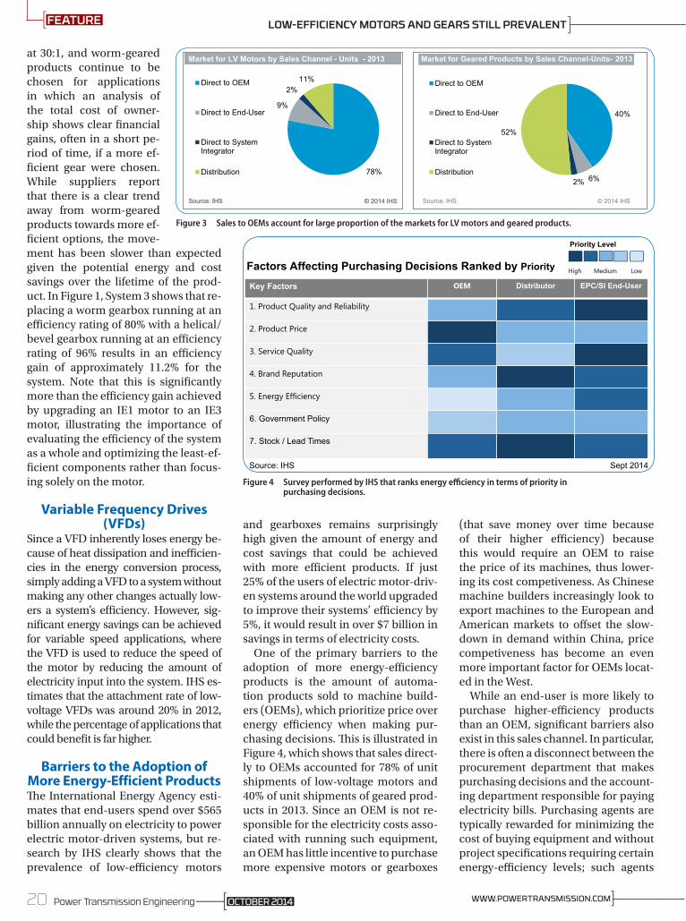
One of the primary barriers to the adoption of more energy-efficiency products is the amount of automa-tion products sold to machine build-ers (OEMs), which prioritize price over energy efficiency when making pur-chasing decisions. This is illustrated in Figure 4, which shows that sales direct-ly to OEMs accounted for 78% of unit shipments of low-voltage motors and 40% of unit shipments of geared prod-ucts in 2013. Since an OEM is not re-sponsible for the electricity costs asso-ciated with running such equipment, an OEM has little incentive to purchase more expensive motors or gearboxes
(that save money over time because of their higher efficiency) because this would require an OEM to raise the price of its machines, thus lower-ing its cost competiveness. As Chinese machine builders increasingly look to export machines to the European and American markets to offset the slow-down in demand within China, price competiveness has become an even more important factor for OEMs locat-ed in the West.
While an end-user is more likely to purchase higher-efficiency products than an OEM, significant barriers also exist in this sales channel. In particular, there is often a disconnect between the procurement department that makes purchasing decisions and the account-ing department responsible for paying electricity bills. Purchasing agents are typically rewarded for minimizing the cost of buying equipment and without project specifications requiring certain energy-efficiency levels; such agents
78%
9%
2%11%Direct to OEM
Direct to End-User
Direct to SystemIntegrator
Distribution
Market for LV Motors by Sales Channel - Units - 2013
Source: IHS © 2014 IHS
Market for LV Motors by Sales Channel - Units - 2013
Source: IHS © 2014 IHS
40%
6%2%
52%
Direct to OEM
Direct to End-User
Direct to SystemIntegrator
Distribution
Market for Geared Products by Sales Channel-Units- 2013
Source: IHS © 2014 IHS
Figure 3 Sales to OEMs account for large proportion of the markets for LV motors and geared products.
Figure 4 Survey performed by IHS that ranks energy efficiency in terms of priority in purchasing decisions.
Key Factors OEM Distributor EPC/SI End-User
1. Product Quality and Reliability
2. Product Price
3. Service Quality
4. Brand Reputation
5. Energy Efficiency
6. Government Policy
7. Stock / Lead Times
Factors Affecting Purchasing Decisions Ranked by Priority
Priority Level
High Medium Low
Source: IHS Sept 2014
20 Power Transmission Engineering ]————WWW.POWERTRANSMISSION.COMOCTOBER 2014
FEATURE LOW-EFFICIENCY MOTORS AND GEARS STILL PREVALENT
The Gearmotor Gold Standard
©2013 Baldor Electric Company
• Energy Efficient
• Unmatched Quality
• Superior Reliability
• Quickest Delivery Available
• Made in the USA
The Baldor•Dodge® Quantis® Gold gearmotor combines the Baldor•Reliance® premium efficient Super-E® motor with the superior Quantis gearbox, making the Quantis Gold the most energy efficient, coolest running gearmotor in the world.
Available as in-line helical or right angle helical bevel c-face units, 1/2 to 10 Hp, the Quantis Gold raises gearmotor energy efficiency, quality and reliability to a new gold standard.
baldor.com 479-646-4711
are also hesitant to a purchase a more ex-pensive product.
The lack of emphasis on energy efficiency is illustrated in Figure 5, which shows the results of a survey re-cently performed by IHS. When asked to rank the importance of various factors con-sidered for purchas-ing decisions, OEMs valued product price most highly, distribu-tors valued brand rep-utation and lead times, and end-users valued product quality and reliability. Energy effi-ciency appeared at the bottom of the list for OEMs, and was ranked less than or equal to four other key factors by the end-users who stand to benefit the most from the adop-tion of such products.
ConclusionWhile disheartening, these statistics show there is still a sig-nificant opportunity to achieve energy savings through the adoption of more energy-efficient products. Since prod-ucts with higher efficiency also typically have a higher profit margin, suppliers of low-voltage motors and geared prod-ucts continue to play an important role by marketing the benefits of their more energy-efficient products. The current emphasis on the total cost of ownership will continue to drive end-users to more energy-efficient products, both in their own purchasing decisions for automa-tion components and in their require-ments for the machines they purchase from OEMs.
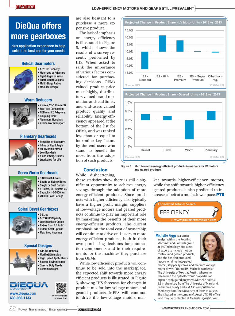
While low efficiency products will con-tinue to be sold into the marketplace, the expected shift towards more energy efficient products is illustrated in Figure 5, showing IHS forecasts for changes in product mix for low-voltage motors and geared products. MEPS will continue to drive the low-voltage motors mar-
ket towards higher-efficiency motors, while the shift towards higher-efficiency geared products is also predicted to in-crease, albeit at a much slower pace.
www.diequa.com630-980-1133
See our completeproduct line!
DieQua offersmore gearboxesplus application experience to helpselect the best one for your needs
• 1-75 HP Capacity• Motorized or Adapters• Right Angle or Inline• Shaft Mount Designs• Multi-Stage Ratios• Modular Design
Helical Gearmotors
• 7 sizes, 28-110mm CD• Fret-free Connection• NEMA or IEC Adapters• Coupling Input• Aluminum Housings• 2-Side Worm Support
Worm Reducers
• Precision or Economy• Inline or Right Angle• 40-155mm Frames• Low Backlash• 1 and 2 Stage Ratios• Lubricated for Life
Planetary Gearheads
• 3 Backlash Levels• Shafts or Hollow Bores• Single or Dual Outputs• 11 sizes, 25-200mm CD• Capacity: 10-7000 Nm• 20,000 Hour Ratings
Servo Worm Gearheads
• 9 Sizes• 1-250 HP Capacity• Low Backlash Option• Ratios from 1:1 to 6:1• Output Shaft Options• Machined Housings
Spiral Bevel Gearboxes
• Add-On Options• Modified Dimensions• High Speed Applications• Special Environments• Special Duty Needs• Custom Designs
Special Designs
third-vertical.indd 1 9/24/13 3:18 PM
-15.0%
-10.0%
-5.0%
0.0%
5.0%
10.0%
15.0%
IE1 -Standard
IE2 - High IE3 -Premium
IE4 - SuperPremium
Other/non-reg.
Projected Change in Product Share - LV Motor Units - 2018 vs. 2013
Source: IHS © 2014 IHS
-1.5%
-1.0%
-0.5%
0.0%
0.5%
1.0%
Helical Bevel Worm Planetary
Projected Change in Product Share - Geared Units - 2018 vs. 2013
Source: IHS © 2014 IHS
Figure 5 Shift towards energy-efficient products in markets for LV motors and geared products
Michelle Figgs is a senior analyst within the Rotating Machines and Controls group at IHS Technology. Her areas of expertise include motion controls and geared products, and she has also produced reports on drive-integrated motors, stepper systems, and medium voltage motor drives. Prior to IHS, Michelle worked at The University of Texas at Austin, where she researched the optoelectronic properties of organic conjugated polymers. Michelle holds a B.S in chemistry from The University of Maryland, Baltimore County and a M.A in computational chemistry from The University of Texas at Austin. She is based in the company’s Austin, TX, US office and may be contacted at [email protected].
EFFICIENCY
For Related Articles Search
at www.powertransmission.com
22 Power Transmission Engineering ]————WWW.POWERTRANSMISSION.COMOCTOBER 2014
FEATURE LOW-EFFICIENCY MOTORS AND GEARS STILL PREVALENT

Scan this code with your smartphone for more information.
http://esp.to/wyZPin
The brands you count on from the people you trust...that’s Rexnord and Motion Industries.
Rexnord’s new Thomas® XTSR52 and XTSR71 Disc Couplings provide the highest value solution for rotating equipment, including higher torque, lower mass and an all-metric design. Combining compact size and powerful performance, the Thomas XTSR Disc Couplings feature simple installation and maintenance, and strengthened operation and safety.
And, you can find Rexnord’s Thomas Disc Couplings at your local Motion Industries location. Our local sales and service specialists are experts in application and technical support, providing the parts and the know-how you need to stay up and running.
Call. 800-526-9328Click. www.motioncanada.comVisit. Over 50 Locations
Call. 800-526-9328Click. www.motionindustries.comVisit. Over 550 Locations
Téléphone 800 526-9328Clic www.motioncanada.comVisite Plus de 50 succursales
MI17B12 Rexnord PTE-OCT.indd 1 9/9/14 1:41 PM
Decentralizing servo technology can bring machine and plant construction savings during installation. Two ad-ditional advantages include reduced cabinet heat loads and more straight-forward drive architecture. The ques-tion arises, however, which technology is better, an integrated motor/drive so-lution or a detached motor and drive?
So often in life the answer to a ques-tion is neither A or B, but instead C. This is true for the discussion of decen-tralized versus centralized servo tech-nology in determining the best system. What architecture is best from a com-mercial and technical standpoint for a particular application? Instead of A or B, the answer C comes about through mixed architectures, a coexistence of both types. In this case the two ap-proaches can be easily combined when the drives have a large number of com-mon features. As such, standardization of these platforms is the best approach (Fig. 1).
The Centralized ArchitectureIn contrast to horizontal convey-ing, where decentralized servo drives are common, centrally located servo drives still dominate the market for highly dynamic and precise motion control. Servo drives, along with other control components, sometimes in-cluding a full-blown industrial PC, reside together in a control cabinet protected from the outside world. Connection to the motors is in a star-shaped structure, each having control and power cables. Because heat loss is centrally generated, effective air con-ditioning is needed in the cabinet.
The Decentralized AlternativeDecentralized servo technology fol-
lows the basic principle of shifting the individual motor control from the
central control cabinet to be closely located to the process. This architec-ture makes necessary a robust design providing a high degree of environ-mental protection. The advantage lies particularly in terms of motor cabling. Two other advantages are improved electromagnetic compatibility behav-ior and the widespread distribution of heat loss, reducing the cost or need for a centralized cabinet climate control system.
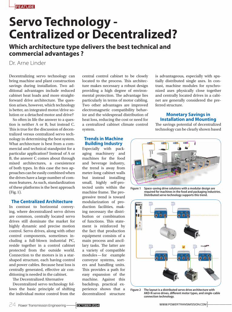
Trends in Machine Building Industry
Especially with pack-aging machinery and machines for the food and beverage industry, the trend is away from meter-long cabinet walls but instead installing small, highly self-pro-tected units within the machine frame. The pro-gressive trend is toward modularization of pro-duction facilities, mak-ing necessary the distri-bution or combination of functions. This state-ment is reinforced by the fact that production equipment consists of a main process and ancil-lary tasks. The latter are a variety of compatible modules — for example conveyor systems, sort-ers and handling units. This provides a path for easy expansion of the machine. Against this backdrop, practical ex-perience shows that a decentralized structure
is advantageous, especially with spa-tially distributed single axes. In con-trast, machine modules for synchro-nized axes physically close together and centrally located drives in a cabi-net are generally considered the pre-ferred structure.
Monetary Savings in Installation and Mounting
The savings potential of decentralized technology can be clearly shown based
Servo Technology - Centralized or Decentralized?Which architecture type delivers the best technical and commercial advantages ?Dr. Arne Linder
Figure 1 Space-saving drive solutions with a modular design are required for machines in the food and packaging industries. Distributed servo technology supports this trend.
Figure 2 The layout is a distributed servo drive architecture with AKD-N servo drives, different motor types, and single-cable connection technology.
24 Power Transmission Engineering ]————WWW.POWERTRANSMISSION.COMOCTOBER 2014
FEATURE

on a real metalforming machine hav-ing eight axes. The first axis is located five meters away from the control cabi-net with each additional axis located three meters further. A centralized control system would be character-ized by a central control cabinet hous-ing the drives, with each motor having separate shielded power and feedback cables adding up to 248 meters of cable (Figs. 2-3).
Instead, a combination of a single power supply module and eight de-centralized servo controllers would reduce the cable requirement to 34 meters. The calculation: A single five-meter hybrid cable supplying power and field bus for axis control is con-nected between the power supply module and the first decentralized controller. A single hybrid cable three meters long connects each additional drive for a total of 21 meters. Because we assume that each motor is located 1 meter away from each decentralized drive and that the drives use a one-cable motor connection technology, only eight additional meters of cable are required. Overall, the decentral-ized system reduced the cable require-ments from 248 to 34 meters, a savings of 86 percent. These figures represent an idea of the overall monetary gains for the OEM, including cable costs and reduction in assembly effort. When the axes require additional I/O, the reduc-tion in cabling is even more obvious. Instead of 372 meters, only 42 meters are needed, a corresponding savings of 89 percent.
Another benefit of the relocation of drives is the reduction of power dis-sipated in the control cabinet. This ef-fectively reduces the requirements for air conditioning, thus providing direct saving for both the OEM and end user. As such, the control cabinet air condi-tioner can be reduced in size or com-pletely eliminated, reducing costs for hardware and subsequent operation and ultimately increasing energy effi-ciency.
Technical Advantages by Decreasing Complexity
The AKD -N series Kollmorgen drives provide IP67 protection and connec-tion via an eleven millimeter diameter
hybrid cable to the cen-tral supply module in the control cabinet. This sin-gle cable provides power and communications without the need for any additional cabling. Each AKD -C supply module can support two strings of AKD -N drives up to 4 kW each, and up to 8 AKD -N drives per
2014 AHR EXPO®
WINNER
Figure 3 KOLLMORGEN specifically designed the distributed servo drives for the AKD-N range as distributed devices, so that there are no deductions in power density.
25Power Transmission EngineeringOCTOBER 2014
FEATURE

string. Safe Torque Off shutdown per-formed via the hybrid cable comes as standard, and can be implemented for each drive individually or as group. Also, only one cable is necessary be-tween the distributed servo controller and its connected motor thanks to a new single-cable technology. Two ca-bles are no longer required to provide
motor power and feedback. In material handling applications where precise motion is demanded, separate cable trays or tow chains are often required for motor and feedback cables. This requirement is now reduced because there is much less cabling (Figs. 4-5).
Winning with Increased Design Freedom
Sample calculations show that the decentralized servo technology saves space in combination with the single-cable connection technology between motor and controller. This benefit re-sults in smaller cable trays, lighter drag chains, and more compactness, giving more design freedom in the develop-ment of new machines. This freedom resulted primarily from the fact that the distributed technology extends modularization capabilities in com-parison to the unflexible, central con-trol design. The bottom line is that this allows new OEM plants to create new machines from already developed modules, making the engineering more efficient.
Distributed Drive Technology as a Hybrid
A second way to decentralize is with the use of a hybrid integrated solution. These are combined motor and servo controller units without the need for external wiring. This so-called “pig-gyback” solution has the disadvan-tage of drive derating with increased ambient temperature. The higher the ambient, the more performance re-duction occurs in order for the drive to self-protect from overheating. This re-lationship ensures in practice that the motors must be larger than otherwise necessary to give the required perfor-mance within acceptable temperature limits for the electronics. Typical servo tasks such as rapid acceleration and deceleration during positioning can be
ENGINEERED TO KEEP YOU MOVING.(888) 994-2663 www.conedrive.com
Visit us at booth S-1832 November 2-5.
Our NEW Stainless Steel gearboxes are IP 69K rated. The smooth and rounded surface allows for easy cleaning.
• Non-fretting motor connection
• IP 69K rated
• Dimensional drop-in for most worm gear manufacturers
• Cone Drive TRUE Double-Enveloping worm gearing
Figure 4 It´s true that at first glance they´re just cables, but these push up the installation costs and take up space inside machines. The comparison between the central and distributed layout speaks for itself.
Figure 5 The torque motors in the KBM series reveal their full strength when space is really tight in machines.
26 Power Transmission Engineering ]————WWW.POWERTRANSMISSION.COMOCTOBER 2014
FEATURE SERVO TECHNOLOGY - CENTRALIZED OR DECENTRALIZED?

Backed By:Complete Plant Surveys Toll Free Tech Support Lubrication SoftwareColor Coded Machine Tags Lubrication Training Follow-Up Oil Analysis
ESPLubriplate ®
Extra Services Package
Lubriplate® Lubricants Quality Products And Services
A Dedicated OEM Department• OEM Technical Support - Dedicated to helping you select the best lubricant for a given application.• Helps ensure equipment performance & service life.
A Wide Range of Quality Products• A Full Line of Advanced Technology Synthetic Lubricants.• Traditional Petroleum-Based Oils and Greases.• NSF H-1 Registered, Food Machinery Grade Lubricants.
A Worldwide Distribution Network• A Strong Worldwide Distribution Network. • Ensures availablity of correct service lubricants regardless of equipment location.
A Complimentary Services Package
The Brand OEMs Can TrustWhen Specifying Lubricants.
More and more original equipment manufacturers are specifying Lubriplate Lubricants for their machinery. Why? With 144 Years of Lubrication Experience, they know Lubriplate has the Quality Products and Services to meet their needs, the needs of their equipment and the needs of their customers.
Lubriplate® LubricantsNewark, NJ 07105 / Toledo, OH 43605Contact Ellen GIrard, Lubriplate’s OEM Marketing Analyst 908-489-7355 or [email protected]
To visit us on Facebook, Twitter or LinkedIn, go to www.lubriplate.com and click on the desired icon.

WE SHIP In as fEW as 5 days
When Weeks ARE Just toO long ...
By combining the latest in ring rolling technology with experienced people, McInnes delivers the best value in carbon, alloy and stainless steel rolled rings.
Carbon · alloy stainless steel
Rings · 4˝ - 144˝ OD
1.800.569.1420 www.McInnesRolledRings.com
especially difficult in the design of hybrid solu-tions due to the problem of effectively dissipating heat (Fig. 6).
However, separating the motor and drive at this point prevents the inherent design-related derating. This solution provides the basis for smaller motors in com-bination with better en-ergy efficiency. In many cases, integrated com-binations are usually fo-cused on a single motor type, limiting flexibility in the machine design. In contrast, any Kollmorgen brushless motor type can be connect-ed to the decentralized AKD-N servo drive. These motors include conven-tional or direct-drive rotary and linear types, providing true design freedom and optimum performance.
An Integration ExampleIn conclusion, to clarify these relation-ships an example of servo drive tech-nology for a food processing machine will be shown. The process begins with the cutting of sausage and cheese by a so-called slicer. The product is con-veyed onto a belt. The process is not just a simple matter of conveying a sau-sage stack from point A to point B, but to transport it as well-defined shingles. The need for highly dynamic single-axis positioning system is clear. The question now arises how to integrate the required sophisticated motion control functions while maintaining centralized machine control. The slic-er provides a good example because it represents a specific decentralized axis because its high power require-ment cannot be met with a decentral-ized drive. The primary objective from the manufacturing perspective is to harmonize highly diverse functional requirements for a wide combination of centralized and decentralized solu-tions. The Kollmorgen AKD-N drive deliberately focuses on the use of a
centralized AKD platform. It provides appropriate technology to allow the optimum selection of a motion solu-tion for the performance task required, offered through the wide variety of compatible actuators. For more information:Kollmorgen203A West Rock RoadRadford, VA 24141Phone: (540) 633-3545www.kollmorgen.comKollmorgen Europe GmbHPempelfurtstrasse 140880 RatingenGermanyPhone: +(49) 2102-9394-2195
Figure 6 More order in the tangle of cables: If servo drives are used right next to motors, the elaborate power wiring from a central control cabinet can be dispensed with. Installation becomes clearer.
Dr. Arne Linder is a product manager for Kollmorgen, a leading provider of integrated automation and drive systems, along with corresponding components for machine builders.
SERVO
For Related Articles Search
at www.powertransmission.com
28 Power Transmission Engineering ]————WWW.POWERTRANSMISSION.COMOCTOBER 2014
FEATURE SERVO TECHNOLOGY - CENTRALIZED OR DECENTRALIZED?

Big on quality. Big on value.C&U Americas is your source for high performance bearings with best-in-industry value.
As one of the world’s top 10 bearing manufacturers and China’s largest,
C&U produces over 2.3 million high-quality bearings a day and can easily
meet all of your bearing needs from original equipment to aftermarket.
We offer a broad portfolio of over 3,000 bearing styles and sizes
from 1.5 mm inner diameter to 4000 mm outer diameter.
C&U offers world-class manufacturing capabilities with 9 bearing manufacturing
centers, 34 bearing plants, and 22 vertically integrated component plants.
From our North American headquarters in Plymouth, Michigan, we’re able
to offer exceptional value along with complete application engineering and
customer service support.
C&U Americas, LLC | Plymouth, MI (734) 656-0260 | www.cubearing.com | [email protected]
CU178 PowerTransmission_BearingCity_FullP_2-14_V1.0.indd 1 1/24/14 10:29 AM

For Mark Findlay of UK specialist drive-line consultancy Drive System Design, reduc-ing gear noise to suit the low noise levels in an electric vehicle cab-in has meant throwing away the rule book.
The high-speed electric motor in an electric vehicle (EV) usually requires a train of reduction gears to achieve suitable road wheel speeds, while the most efficient EVs also have multi-speed, geared transmissions. With no combustion engine to mask the sound, it has become critical for customer ac-ceptance that these gears achieve new standards of silent operation, and that has meant applying new design ap-proaches.
Traditional Methods Prove Inadequate
Historically, designers have selected the gear macro geometry to provide the required durability with a specified duty cycle, and then looked to the mi-cro geometry to deliver satisfactory re-finement. Old rules-of-thumb — such as choosing overlap ratios and total contact ratios with values just higher than integer numbers — are still tout-ed as “safe” guidelines for low-noise designs in some quarters. The inad-
equacy of this method has been thor-oughly exposed by the demands of the EV industry where a modern, systems approach is delivering a promising combination of operational refine-ment and robustness to manufactur-ing tolerances.
The systems approach considers the component, not in isolation, but as an integral part of a wider system in which it interacts with other parts. It gener-ates a more complete understanding of the issues, and prompts solutions that may sometimes be counter-intu-itive. For example, reducing the helix angle on a gear can, by reducing thrust at the mesh, lead to better alignment through reduced deflection, impart-ing better noise performance despite the apparent loss of contact ratio. Ef-fective management of misalignment and deflection makes possible highly successful designs using contact ratios below the traditional norms for helical gears in mainstream automotive appli-cations.
By correctly specifying the macro geometry — and thus satisfying the re-quirements for durability, good NVH and high efficiency — the need for so-phisticated or complex micro geom-etry can be eliminated, making the gears much more forgiving in manu-facture. The challenge is to identify the appropriate macro geometry.
Whatever the geometry — as the teeth deflect, any meshing pair will generate excitation from transmission error under load. The response of the system to this excitation, including its harmonic content, is just as important as the gear geometry in achieving a refined product. A systems approach can also help address this aspect of the design.
System-Level InteractionsAt Drive System Design, when a noise issue in a transmission or axle is inves-tigated, we model the whole system as far as the points where it mounts to the vehicle in order to identify whether the
problem is caused by the response of the casings or mountings to the excita-tion coming from the gear mesh. This explains why gear noise can be so dif-ficult to eradicate by changes to the gear geometry; i.e. — the real culprit is a system -level interaction — not a component-level “defect.”
Every element of a system has a number of potential modes of vibra-tion, each at a characteristic frequen-
Electric Vehicles Need Quieter GearsMark Findlay
]————WWW.POWERTRANSMISSION.COM
FEATURE
OCTOBER 2014Power Transmission Engineering30
cy. By the time we include all the gears, shafts, bearings, casings and mount-ings in a typical system, we have a huge potential for interaction where differ-ent modes align with each other. The use of sophisticated analytical tools, such as MASTA software, allows us to identify potential issues and separate the system modes to avoid undesirable responses, detected as unwanted noise by the observer.
In practice, this often means that a noise concern that the client perceives as a gear mesh issue is actually elimi-nated by measures such as adding stiffening ribs to a transmission cas-ing or re-specifying the mounting bush characteristics of an axle assembly. The effect on production costs is usu-ally insignificant, and the investigation may even uncover the potential to use
a more economical manufacturing route. (A recent project for a client in-vestigated the prospects for replacing helical gears with spur gears, so great had been the noise reduction.)
Though it has taken the particular needs of EV manufacturers to compel the automotive industry to take note of the value of using a systems approach to gear design, the benefits can be ap-plied to many other applications.
Keep in mind that specifying in-creasingly high gear quality or com-plex micro geometry in order to ad-dress a noise concern will not only add cost, it may not work. So the next time a customer tells you your gears are too noisy, and asks for suggestions, it may be time for them to take a systems ap-proach to the problem.
AUTOMOTIVE GEARS
For Related Articles Search
at www.powertransmission.com
31Power Transmission EngineeringOCTOBER 2014
FEATURE
For more information:Drive System Design, North America38855 Hills Tech DriveUnit 500Farmington Hills, MI 48331Phone: (248) [email protected]
Drive System Design, EuropeUnit B Berrington RoadSydenham Industrial EstateLeamingtonCV31 1NBPhone: +44(0) 1926 [email protected]

ASK THE EXPERT
Answers Provided by: Romax Technology LimitedAre there any special work surface or site requirements
for installing bearings?All bearings require meticulous attention to detail when fitting. The bearings need to be stored in their original wrappings in a clean and dry environment. When fitting bearings it’s important to avoid any contamination to avoid potential damage to particles. Therefore, when fit-ting, we recommend that the bearings should remain in their wrappings until the very last moment, and they need to be unwrapped in a clean, draught free environment.
We recommend using induction heaters, with thermo-static control, to ensure the bearings are evenly heated to allow successful fitting without damaging the bearing. The fitting of the bearing is of critical importance to its life. The designated clearances must be achieved in order to give the bearing any chance of lasting.
As an example, Romax often fits bearings when install-ing a double-row TRB of, say, 250 mm OD; this might have a design axial clearance of 220 microns. A variance of more than ±20 microns could halve the life of the bearing. As a result, it is important to ensure that your mechanical de-sign can be realized in the flesh. Any damage to either the races or the rollers will significantly reduce the life of the bearing, so it is important to consider how the bearing will be held and or supported while it is being fitted.
Accounting for the application, what is the best way to choose a bearing lubrication method?
You need to consider cooling requirements, packaging space available in your design and life cycle cost. You will also need to consult the bearing supplier for guidance on cooling requirements; there are usually simple empirical rules based on load and speed.
Packaging requirements mean that it can often be diffi-cult to find space for the required seals for each side of the bearing or to find a sealed variant for your bearing.
If cooling requirements are low, then grease can be the lower cost. If the life of the application exceeds the grease life, then you need to take account of the cost of re-greasing.
Oil bath introduces many extra components and costs into your application: pump, filters, oil ways, and magnetic plug. And like grease, the oil may also need changing at the end of its life.
In lubricating the bearing, is anything gained by using extra grease?
The best way to use grease in a bearing is to only fill the un-swept volume so that the bulk of the grease is not con-tinuously churned as the bearing rotates. Oil will gradually bleed out of the grease pack onto the rolling surfaces.
Extra grease (more than recommended) often causes churning of the grease and increases friction torque and heating of the bearing. The grease may even escape from the bearing due to the reduction in grease viscosity and over-temperature of the seals and can therefore be a bad thing. For example: depending on the application, on a wind turbine there is circumstantial evidence of over greasing leading to bearing over temperature; however this can be very different from changing grease regularly, which can prolong the bearing life. Debris in old grease can be damaging and ideally you want lubrication, not grinding paste.
Is less bearing radial clearance a good thing?It is very complicated; reduced radial clearance can affect the bearing life either beneficially or detrimentally or very little — depending on how a system deflects and loads are shared. Romax uses its software tools specifically to study this question in great detail for specific applications. If the clearance is too low, there are risks of additional failure modes such as cage breakage or bearing overheating.
For more information:Romax Technology LimitedCentre University of NottinghamInnovation Park Triumph Road Nottingham NG7 2TU United Kingdom(Phone): +44 (0)115 951 88 [email protected]
Bearing Basics
BEARINGS BASICS Q&A:IN CASE YOU DIDN’T KNOW…
THE QUESTION
BEARINGS
For Related Articles Search
at www.powertransmission.com
32 Power Transmission Engineering ]————WWW.POWERTRANSMISSION.COMOCTOBER 2014

YA S K AWA A M E R I C A , I N C .D R I V E S & M O T I O N D I V I S I O N
1 - 8 0 0 -YA S K AWA YA S K AWA . C O M
Follow us: For more info:http://Ez.com/yai687
©2014 Yaskawa America Inc.
NOTHING GOODHAPPENS AFTERMIDNIGHT
Nobody wants that middle-of-the-night-call telling you systems are down. Not you. Not us. And, certainly not the guy with the problem. That’s one of the reasons you should turn to Yaskawa for drives and motion control.
Trust your operations to Yaskawa and the phone won’t ring at night. The boss won’t be in your o� ce. And, maintenance won’t be breathing down your neck with another fi re to put out. Trust Yaskawa and you’ll get a good night’s sleep.
Rest easy tonight. Call Yaskawa today.

Premature Bearing Failures in Wind Gearboxes and White Etching CracksKenred Stadler and Arno Stubenrauch
Wind turbine gearboxes are subjected to a wide variety of operating conditions, some of which may push the bearings beyond their limits. Damage may be done to the bearings, resulting in a specific premature failure mode known as white etching cracks (WEC), sometimes called brittle, short-life, early, abnormal or white structured flaking (WSF). Measures to make the bearings more robust in these operating conditions are discussed in this article.
Ambitious, worldwide renewable energy targets are pushing wind energy to become a mainstream power source. For ex-ample, the Global Wind Energy Council GWEC (Ref. 1) ex-pects that the currently installed wind energy capacity of 200 GW will double within three to four years, keeping open the aspir ational goal of 1,000 GW of installed capacity by 2020.
Despite high wind turbine availability (>96% depending on turbine) and a relatively low failure rate of mechanical com-ponents compared with electrical components, failures of mechanical drivetrains still create high repair costs and rev-enue loss due to long downtimes (Ref. 2).
In most wind turbine concepts a gearbox is commonly used to step up the rotor speed to the generator speed. Today, the actual service life of wind turbine gearboxes is often less than the designed 20 years. Failures can be found at several bearing locations, namely the planet bearings, intermediate shaft and high-speed shaft bearings (Fig. 1).
Much premature wind gearbox bearing damage results in a failure mode that is not caused by the classic rolling contact fatigue (RCF) mechanisms (Fig. 2). While these classic mech-anisms are sub-surface-initiated fatigue — as well as surface-initiated fatigue — and can be predicted by standard bearing life calculation methods (see ISO 281 and ISO/TR 1281-2), premature crack failures are not covered by these methods. However, attempts to calculate bearing life have been made when detailed in-formation of the case is available (e.g., local effect of hoop stresses) (Ref. 37).
ISO 15243 describes the visual appear-ance of the classic rolling contact fatigue mechanisms. White etching refers to the appearance of the altered steel micro-structure when polishing and etching a microsection. The affected areas — con-sisting of ultrafine, nano-recrystallized carbide-free ferrite — appear white in a light optical micrograph due to the low etching response of the material.
Known to occur only occasionally in some industrial applications such as paper mills, continuous variable drives,
Figure 1 Standard multi-megawatt (MMW) wind gearbox (for 3-point suspension) having a low-speed planet stage and two spur wheel sections (high-speed intermediate shaft and high-speed shaft) with highlighted bearing locations that can be affected by premature bearing failures.
Figure 2 Classic fatigue failure modes vs. cracks and WEC *micrograph, according to Reference 5, **micrograph according to Reference 6.
This article first appeared in Evolution — the SKF business and technology magazine (evolution.skf.com).
34 Power Transmission Engineering ]————WWW.POWERTRANSMISSION.COMOCTOBER 2014
TECHNICAL

marine propulsion systems, crusher mill gearboxes or lifting gear drives, in wind applications the frequency of premature failures seems to be higher (but might also be related to a larg-er population of installed machines). Commonly, early cracks have occurred within the first one to three years of oper ational time or at 5 to 10 % of the calculated rating life (Fig. 3).
Mostly occurring on the inner ring (Fig. 4), the visual ap-pearance of early cracks varies from straight or “axial cracks” to cracks in combination with small spalls and large/heavy spalling. Based on SKF’s knowledge gained through increased field experience, it is concluded that early failures by cracks are neither linked to a particular type of bearing (Fig. 5), nor to a particular standard heat treatment (Fig. 6; Refs. 6 –10).
The failure appearance, however, is associated with the heat treatment (e.g., residual stress field), the stage of failure progress, and, very likely, also to the operating conditions or bearing position (e.g., stress field from loading). As can be seen in Figure 6, for early cracking in this specific application, cracks in martensite rings tend to grow straight into the ma-terial (suggesting the straight “axial” crack appearance, e.g., Fig. 6a), whereas in bainitic (Fig. 6b) as well as in carburized case-hardened rings, the cracks tend to grow circumferen-tially below the raceway (explaining the spalling/flaking type of appearance; e.g., Fig. 6c). Nevertheless, in a very advanced failure stage, the inner ring raceways are often heavily spall-ed, independent of the heat treatment.
Challenges Due to Operating Conditions in Wind Turbine Gearboxes
Wind turbine gearboxes are subjected to a wide variety of op-erating conditions that may push the bearings beyond their limits (e.g., with respect to load, speed, lubrication and com-binations of these). The wind energy segment faces some of the toughest challenges for extending bearing life and reduc-ing the occurrence of premature failures while at the same time reducing the overall cost of energy.
There are many opinions in the public conversation sum-marizing common indications of severe operating conditions in conjunction with premature failures in wind turbine ap-plications. These include:• Periods of heavy and dynamic loads/torques – leading to
vibrations and rapid load changes (e.g., transient raceway stress exceeding 3.1 GPa, heavy loads of 15,000 per year, impact loads) (Refs. 6 – 7; 11–15;17–18).
• Depending on turbine type, additional radial and axial forces by the rotor, axial motion of the main shaft – leading to dynamical loading, higher stresses of gearbox components especially at the first stage (Refs. 19 –20).
• Occasional connecting and disconnecting of the generator from the power grid – leading to torque reversals and bouncing effects (e.g., can lead up to 2.5 – 4 times higher nominal torque, impact loads) (Refs. 12, 15, 21).
• Rapid accelerations/decelerations and motions of the gearbox shafts (Refs. 13, 15).
• Misalignment, structural deformations (nacelle hub, housings) (Ref. 11).
• Lubricant compromise between needs of gears and bearings as well as between low- and high-speed stages, insufficient oil drains and refill intervals (Ref. 22).
Figure 3 Typical in premature failing of industrial machinery is that bearings from identical machines in the same specific surroundings are failing within a consistent and short time period. The slope difference is a predictor of “other than classic fatigue.” Those having had a short service life are likely to have a short service life again if no further actions on the bearing-shaft-housing system are taken.
Figure 4 Failure appearance: a) straight cracks; b) straight cracks and small spalls; and c) spalls.
Figure 5 Examples of typical bearing types that can be affected: a) tapered roller bearing; b) cylindrical roller bearing; and c) spherical roller bearing.
Figure 6 Crack growth patterns in standard heat treatment: a) martensite; b) bainitic; and c) case hardened (case carburized) 6.
35Power Transmission EngineeringOCTOBER 2014

• Harsh environmental conditions – eventual large temperature changes and consequently larger temperature differences between the bearing inner ring and housing than expected when starting up, dust, cold climate, offshore, moisture (Ref. 23).
• Idling conditions – leading to low load conditions and risk of skidding damage (adhesive wear) (Ref. 23).
• Some design requirements can be conflicting, e.g., increasing rolling element size will increase the load carrying capacity but simultaneously increase the risk of cage and roller slip and sliding damage (Refs. 6 – 7; 17, 23).
As stated, bearings may fail for other reasons not attrib-uted to falling below best practice standards (Refs. 24 – 25) and from other industrial experiences. Statistical evaluations of a limited number of offshore wind turbines (Ref. 2) indi-cate clearly a correlation between failure rate, wind speed and heavy and fluctuating loads. The trend towards larger turbine sizes with higher power-to-weight ratios will invari-ably lead to more flexible supporting structures (Ref. 11) that, in turn, will influence the load sharing and load distribution within the rolling bearings as well as on other drive compo-nents. According to Reference 26, in “young,” heavily loaded applications having a highly innovative product design life cycle, sufficient experiences are often lacking with respect to the machine’s endurance. Independent of wind turbine and gearbox manufacturers, the presence of cracks on bearings is sometimes interpreted as indicative of uncontrolled kine-matic behavior (Refs. 19, 27).
Possible “Rolling Surface Crack” Drivers and Review of Hypotheses
The occurrence of premature failures is heavily discussed within the wind industry and independently investigated by wind turbine manufacturers, gearbox manufacturers and bearing suppliers as well as universities and independent in-stitutions. Unfortunately, a consistent theory does not yet ex-ist. To list and explain all WEC failure root cause hypotheses would go beyond the scope of this paper.
Nevertheless, many of the existing theories from literature can be briefly summarized (Fig. 7). Many papers (for exam-ple, Ref. 10) discuss a local change in the bearing material microstructure into WEC by certain influen cing factors.
As influence factors, the following drivers are often mentioned:Material. Microstructure, heat treatment, natural hydro-
gen content, cleanliness (different type of inclusions), resid-ual stresses, etc.
Loading. Overloads, peak loads, impact loads, torque re-versals, vibration, slip, structural stresses, electric currents, etc.
Environment. Lubricant, additives, corrosion, tribochemi-cal effects, hydrogen generation, temperature gradients, con-tamination (e.g., water), etc.
Others. Mounting (e.g., scratches), transport, quality as-pects, etc.
To increase the complexity, most influencing factors are also correlated.
Thus, driven by a single factor or by a combination of sev-eral factors, WEAs develop locally in the bearing steel matrix. The WEAs will then be the nucleation sites of cracks that fi-nally propagate to the bearing raceway. As a consequence, the bearing will fail by spalling or so-called WSF.
Most common hypotheses can be further divided into hy-drogen-enhanced WEC developments (Refs. 28 – 30), purely load/stress-related WEC developments preferable at inclu-sions (Refs. 31 – 32) or some combination of reasons (Ref. 33).
Some of the above damage mechanisms seem to influence, for example, applications such as:• Paper Mills (e.g., water in oil – corrective action based on
condition of lubrication) (Ref. 34).• Marine Propulsion Systems (e.g., exceeding stresses –
corrective action based on special through-hardened clean steel and stress reduction) (Refs. 32, 34).
• Alternator and Generator Bearings (e.g., damaging current – corrective action by use of special greases and/or hybrid bearings, special steels) (Refs. 6;35–36).
Nevertheless, in general, the relevance of the common WEC hypotheses to premature wind gearbox failures is not as yet sufficiently clear.
Potential Root Cause of WEC in Wind Gearboxes According to SKF Experience
According to SKF experience, most early bearing failures are related to lubrication or other surface-related issues and can partly be estimated by the SKF advanced bearing-life model. SKF internal investigations have revealed that many cracking failure modes in wind gearbox bearing positions most likely have their origin at or near the surface (0 –150 µm) and prop-agate into the material under the influence of a corrosion fa-tigue process (Refs. 6 –7,16).
There are several indicators that can support this hypothesis:Wind gearbox bearings are relatively large, and for larger
bearings the crack initiation and propagation mechanism can differ compared to small bearings (Refs. 6, 16). For instance, a deeper radial cracking is reported in larger bearings at mod-erate loads due to the residual stresses and higher hoop stress (Ref. 37). In case of premature wind gearbox bearing failures, the failure occurrence suggests fast crack propagation. The fast branching and spreading crack propagation can be ex-plained by the presence of chemical influencing factors such as oxygen and ageing products of the lubricant at the crack
Figure 7 According to existing theories in the literature, a) certain influencing factors locally change the microstructure into white etching areas (WEAs); b) WEAs will be the starting points of white etching cracks (WECs); and finally, c) white structure flaking (WSF) due to crack propagation reaches the bearing raceway.
36 Power Transmission Engineering ]————WWW.POWERTRANSMISSION.COMOCTOBER 2014
TECHNICAL

faces/tips (Refs. 6, 16, 38). In a completely sub-surface crack system, we have vacuum conditions and consequently sig-nificantly slower crack growth from pure mechanical fatigue (Ref. 38). In other words, already at an early stage the cracks or crack systems must be connected to the surface to allow the entrance of oxygen and lubricant.
Hydrogen-assisted fatigue can lead to similar effects (Refs. 28, 33), or to accelerated classic rolling contact fatigue (Refs. 6, 35 – 36); however, this would require, for example, aggres-sive corrosive environment or continuous high-frequency electric current passage. The presence of free water leads, likewise, to a highly corrosive environment (Ref. 34), but ele-vated water contents in the lubricants are claimed to be under control by the turbine manufac turers. Moisture corrosion in wind gearboxes is usually not seen during SKF investigations. If that can be excluded, then regenerative passivating tribo-layers usually provide a barrier to corrosion and hydrogen absorption into the steel, if continuous and intact. All told, if hydrogen absorption occurs in the steel, it is detrimental; however, the available evidence of this failure mechanism in wind gearboxes is relatively weak.
Nevertheless, SKF tribochemistry studies confirm the lo-cal generation of hydrogen in severe mixed friction contacts. To continuously generate hydrogen, fresh, interacting metal-lic surfaces are needed. This could lead to a local weakening effect on the surface, facilitating a surface crack generation. However, in wind gearboxes, severe wear is hardly seen on the failed bearing raceways, which would allow hydrogen permeation. Thus, hydrogen permeation through the bearing raceway (without any additional factor) seems not to be likely. A potential additional factor could be the relative aggressive wind oils, eventually in combin ation with contaminants (Refs. 39 – 41). In SKF’s experience, the performance of wind gear-box oils can be distinguished from surface initiated failure mechanisms (Ref. 39) (e.g., surface distress). To quantify the relevance, further investigations are needed. At the moment, the role of hydrogen generation is seen as a local effect gener-ated in the crack systems due to lubricant entry leading to the mechanism of corrosion fatigue cracking (CFC) (Refs. 6, 16).
The normally moderate bearing load conditions in wind gearboxes, the absence of compressive residual stress build-ups (in the area of the maximum von Mises equivalent stress) as well as the decrease in the X-ray diffraction line broaden-ing close to the raceways in failed bearings (e.g., due to mixed friction – shear stresses and vibrations) shown by ma terial response analyses further support a sur-face or near-surface failure initiation (Refs. 6 – 7, 16). Lately, it is known that not only inadequate lubrication conditions, but also certain vibration effects at higher fre-quencies, are able to reduce the film thick-ness and consequently increase the risk for conditions of local mixed friction (Refs. 42 – 43).
According to Reference 44 the genera-tion of WEC networks is less influenced by Hertzian pressures, and most influenc-ing factors are surface based. The often-
disputed role of butterfly crack generation at inclusions, which show a similar altered microstructure as seen in WEC, is considered as part of the classic fatigue mechanism that is well covered in the bearing-life model (Refs. 7, 44 – 45). Little experimental evidence is reported that supports butterfly cracks propagating into WEC networks (Ref. 10).
A high butterfly density is a sign of overstress or very heavy loading (>3 GPa), but excessive loads are claimed not to ex-ist by the turbine manufacturers. This seems to be supported by standard gearbox HALT tests. A highly accelerated life test (HALT) is a stress testing methodology for accelerating product reliability during the engineering development pro-cess. There, the metallurgical investigations often show an elevated number of butterfly formations in the bearings due to heavy-load test conditions, but failed bearings from the field often do not show a significant increase in butterfly for-mations 6, 7. Especially at the high-speed stages, the loads are usually moderate, but bearings can still fail by cracks / WEC without showing a significant population or even individual exemplars of butterflies 6, 7. It seems that standard gearbox HALT tests do need further adaptations to reflect the early failure mechanisms as seen in the field.
Nevertheless, the occurrence of unexpected high sub-surface stress-induced bearing damage 32 also by inclusions cannot be fully excluded as long as the exact contribution of transient running conditions is not fully understood. The ex-act loading of wind gearbox bearings in the field is very much based on wind field simulations, later on further reduced to quasi-static load assumptions; and moderate bearing loads are assumed at nominal conditions. Non-steady-state condi-tions should be kept in mind and are increasingly taken into account by the wind industry.
Potential Mechanism for Damage PropagationThere is a general agreement that it is not nominal wind gearbox operating conditions but rather transient, partly unknown, conditions that lead occasionally to disturbed bearing kinematics, loading and lubrication. Basically, it is assumed that high surface stress concentrations can be reached, e.g., by vibration-induced local mixed friction 6, 16, 47, misalignment or other events as already mentioned. At boundary lubricated patches at asperity level, the stress concentration of the tensile stresses can increase and open a crack under repeated cycles (areas of high stresses just below the roughness) 48, 49.
Figure 8 (A) Roller-raceway contact with areas of local high traction due, for example, to local mixed friction, leading to tensile stresses that can, b) lead to damage such as a small crack; c) surface crack or crack connected to the raceways allows the entry of oil; (for “area d” details, see Fig. 12).
37Power Transmission EngineeringOCTOBER 2014
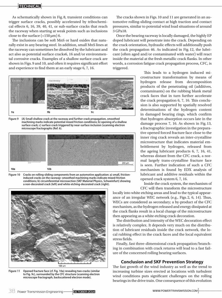
As schematically shown in Fig. 8, transient conditions can trigger surface cracks, possibly accelerated by tribochemi-cal effects 6, 16, 39, 40, 41, or sub-surface cracks that reach the raceway when starting at weak points such as inclusions close to the surface (<150 µm) 6.
The inclusions can be soft MnS or hard oxides that natu-rally exist in any bearing steel. In addition, small MnS lines at the raceway can sometimes be dissolved by the lubricant and act also as potential surface cracks6, 16 and/or environmen-tal corrosive cracks. Examples of a shallow surface crack are shown in Figs. 9 and 10, and often it requires significant effort and experience to find them at an early stage 6, 7, 16.
The cracks shown in Figs. 10 and 11 are generated in an au-tomotive rolling-sliding contact at high traction and contact pressures, similar to potential wind load situations of around 3 GPa18.
Once the bearing raceway is locally damaged, the highly EP doped lubricant will penetrate into the crack. Depending on the crack orientation, hydraulic effects will additionally push the crack propagation 46. As indicated in Fig. 12, the lubri-cant (often aged and/or contaminated with water) will react inside the material at the fresh metallic crack flanks. In other words, a corrosion fatigue crack propagation process, CFC, is triggered.
This leads to a hydrogen induced mi-crostructure transformation by means of hydrogen release from decomposition products of the penetrating oil (additives, contamin ants) on the rubbing blank metal crack faces that in turn further accelerate the crack propagation 6, 7, 16. This conclu-sion is also supported by spatially resolved determin ations of the hydrogen content in damaged bearing rings, which confirm that hydrogen absorption occurs late in the damage process 7, 16. As shown in Fig. 13, a fractographic investigation in the prepara-tive opened forced fracture face close to the inner ring crack reveals an inter-crystalline microstructure that indicates mater ial em-brittlement by hydrogen, released from the ageing lubricant products 6, 7, 16, 41, whereas distant from the CFC crack, a nor-mal largely trans-crystalline fracture face is seen. Further indication of such a CFC mechanism is found by EDX analysis of lubricant and additive residuals within the opened crack system 6, 7, 16.
Inside the crack system, the mechanism of CFC will then transform the microstructure
locally into white etching areas and lead to the typical appear-ance of an irregular WEC network (e.g., Figs. 2, 6, 14). Thus, WECs are considered as secondary; a by-product of the CFC mechanism, as the hydrogen released and energy dissipated at the crack flanks result in a local change of the microstructure then appearing as a white etching crack decoration.
The distribution and intensity of the WEC decoration effect is relatively complex. It depends very much on the distribu-tion of lubricant residuals inside the crack network, the lo-cal rubbing effect in the crack faces and the local equivalent stress fields.
Finally, fast three-dimensional crack propagation/branch-ing in combination with crack returns will lead to a fast fail-ure of the concerned rolling bearing surfaces.
Conclusion and SKF Prevention StrategyThe fast growth of the wind industry as well as the trend to increasing turbine sizes erected at locations with turbulent wind conditions puts significant challenges on the rolling bearings in the drive train. One consequence of this evolution
Figure 11 Opened fracture face (cf. Fig. 10a) revealing two cracks (similar to Fig. 9c), surrounded by the CFC structure (scanning electron microscope fractograph, backscattered electron mode).
Figure 9 (A) Small shallow crack at the raceway and further crack propagation, smoothed machining marks indicate potential mixed friction conditions; b) opening of a shallow surface crack; c) surface crack triggered by near-surface inclusion (scanning electron microscope fractographs (Ref. 6).
Figure 10 Cracks on rolling-sliding components from an automotive application: a) small, friction-induced cracks on the raceway–smoothed machining marks indicate mixed-friction conditions; b) circumferential microsection (SKF Material Physics, Schweinfurt) showing a non-decorated crack (left) and white etching-decorated crack (right).
38 Power Transmission Engineering ]————WWW.POWERTRANSMISSION.COMOCTOBER 2014
TECHNICAL

of a relatively young industry has been premature gearbox bearing failures. Over the years, the discussion in the indus-try was mainly focused on the influence of bearing material and heat treatments. Recently, there is a general agreement that specific wind conditions can lead to disturbed bearing kinematics, loading and lubrication. In other words, the root cause failure will not be found inside the bearing only. The complete application interfaces between the bearing and the gearbox / turbine need to be considered.
The phenomenon of wind gearbox bearing failures by cracks / WEC has been described. A failure hypothesis has been introduced. SKF investigations reveal that cracking fail-ure modes in critical wind gearbox bearing positions most likely have their origin at the surface or near surface and propagate further into the material under the influence of a corrosion fatigue process.
Due to the high complexity of a wind tur-bine as well as the very different bearing locations that can be affected, it is very un-likely that there is only one application con-dition root cause. However, it can be stated that any condition that leads to disturbed bearing kinematics, such as high vibration levels and high sliding friction, should be avoided in order to reduce micro-wear and high tensile stresses.
To effectively support the wind industry, SKF as a bearing manufacturer is focusing on bearing modifications that aim to re-duce the risk of premature bearing failures and increase bearing robustness under the specific conditions of wind gearbox ap-plications. The solution strategy takes into account mainly the hypothesis introduced, but also addresses the common theories on WEC.
Most failure prevention strat egies have been positively con-firmed by internal investigations and SKF field experience. To-day’s state-of-the-art failure prevention measures are:
SKF Special Passivation to:• Stabilize the near surface microstructure• Make the bearing more resistant to chemical attack and
hydrogen• Reduce micro friction under peak loading• Improve running-in
SKF Special Clean Steel for the Most Stressed Component• Reduce further the amount of inclusions that can act as
stress raisers in the material or on the surface
SKF Deep Surface Strengthening Process on the Most Stressed Component (Prototypes)
• Allow a conditioning of the component (shake down – the nominal loading in wind is relatively moderate)
• Increase the resistance against surface crack initiation and sub-surface crack propagation
In summary, a bearing modified as described above can reduce premature failures but needs to be combined with
further improvements of the total design in light of the actual application conditions. Therefore, collaboration between all partners in the design process is needed and advanced cal-culation tools should be used to analyze the operating condi-tions to identify critical operating conditions and to eliminate the potential damaging ones. A stronger focus on compo-nent testing combined with real-size dynamic tests (e.g., in research institutes such as NREL, NAREC, Fraunhofer, etc.) should enable reproduction of damaging operating condi-tions and the testing of potential solutions.
Summary• The rapid growth of the wind industry and its increasing
size and power generation capacity, combined with the harsh operating conditions, create a challenging operating environment for wind turbines.
• Understanding mechanisms, particularly in bearing systems, that can lead to early turbine failures is crucial to delivering equipment that can support the industry’s need for reliable generation combined with cost-effective operation.
• Failure mechanisms are complex, and mitigating the effects of these mechanisms requires not only in-depth research but also collaboration between all sectors of the industry.
Figure 12 (Continuation of Fig. 8): a) After penetration, oil and additives react in the crack flanks locally, producing hydrogen — b and c; the hydrogen transforms locally the microstructure close to the crack system into white etching cracks WECs (from dark etching regions (DER), to white etching areas, WEAs) 6, 7, 16.
Figure 14 Irregular white etching decorated crack network (Ref. 6).
Figure 13 Axial opening of a crack connected to the surface, b) intercrystalline microstructure close to the crack system, c) transcrystalline microstructure elsewhere.
39Power Transmission EngineeringOCTOBER 2014

References1. GWEC. “Global Wind Report;” “Annual Market Update;” 2010-2011.
2. Feng, Y. and P. Tavner. “Introduction to Wind Turbines and Their Reliability & Availability,” Durham Side Event at the EWEC Conference, Warsaw, April 2010.
3. ISO 15243:2004. Rolling Bearings: Damage and Failures; Terms; Characteristics and Causes.
4. ISO 281. Rolling Bearings: Dynamic Load Ratings and Rating Life; ISO/TR 1281-2. Rolling Bearings: Explanatory Notes on ISO 281- Part 2: Modified Rating Life Calculation, Based on a Systems Approach to Fatigue Stresses, and SKF General Catalogue.
5. Swahn, H., P.C. Becker and O. Vingsbo. “Martensite Decay During Rolling Contact Fatigue in Ball Bearings,” Metallurgical Transactions A, Vol. 7A, No. 8, 1976, pp. 1099–1110.
6. Gegner, J. “Tribological Aspects of Rolling Bearing Failures,” Tribology – Lubricants and Lubrication, Kuo, C.-H. (Ed.), In Tech, Rijeka, Croatia, 2011, Chap. 2, pp. 33–94, www.intechopen.com/articles/show/title/tribological-aspects-of-rolling-bearing-failures.
7. Gegner, J. “Frictional Surface Crack Initiation and Corrosion Fatigue-Driven Crack Growth,” NREL Workshop, Broomfield, November 2011.
8. Luyckx, J. “Hammering Wear Impact Fatigue Hypothesis WEC/irWEA Failure Mode on Roller Bearings,” NREL Workshop, Broomfield, November 2011.
9. Holweger, W. “Influence on Bearing Life by New Material Phenomena,” NREL Workshop, Broomfield, November 2011.
10. Evans, M.H. “White Structure Flaking (WSF) in Wind Turbine Gearbox Bearings: Effects of ‘Butterflies’ and White Etching Cracks (WECs),” Material Science and Technology, Vol. 28, No. 1, 2012.
11. Molly, J.P. “Wind Energy – Quo Vadis?” DEWI Magazine, No. 34, February 2009.
12. Heidenreich, D. “A Lean Solution to the Gearbox Life Problem in Wind Turbine Drive Systems,” Hannover Messe 2011.
13. Rosinski, J. and D. Smurthwaite, “Troubleshooting Wind Gearbox Problems,” Gear Solutions 2010. Heege, A., et al. “Matching Experimental and Numerical Data of Dynamic Wind Turbine Loads by Modelling of Defects,” SAMTECH, EWEC 2009.
14. Aguglia, D. and R. Rebeschini. “Power Transformer Role for Gearbox Mechanical Stress Mitigation During Voltage Dips Applied to Doubly Fed Induction Generator-Based WT,” EWEC Warsaw, April 2010.
15. Gegner, J. and W. Nierlich. “Mechanical and Tribochemical Mechanisms of Mixed Friction-Induced Surface Failures of Rolling Bearings and Modelling of Competing Shear and Tensile Stress-Controlled Damage Initiation,” Tribologie und Schmierungstechnik, Vol. 58, 2011, No. 1, pp. 10–210.
16. Nierlich, W. and J. Gegner. “Einführung der Normalspannungshypothese für Mischreibung im älzleitkontakt,” Gleit- und Wälzlagerungen: Gestaltung, Berechnung, Einsatz, VDI-Berichte 2147, VDI Wissensforum, Düsseldorf, Germany, 2011, pp. 277–290.
17. Kotzalas, M.N. and G.L. Doll, “Tribological Advancements for Reliable Wind Turbine Performance,” Phil.Trans. R. Soc. A. 368, 2010.
18. Thomas, T. “Schäden Durch Schwingungen Noch Nicht im Griff,” VDI Nachrichten, 26, Feb. 2010, No. 8. Korzeniewski, T. “Gearbox Protection Concept for Wind Turbine Generator Systems,” DEWI No. 36, 2010.
19. FVA 541 I. Wälzlagerlebensdauer-Windgetriebe, 2010.
20. Kamchev, B. “Wind Energy Encounters Turbulence,” Lubes’n’Greases 2011.
21. Heemskerk, R. “Challenges on Rolling Bearings in Wind Turbines,” VDI Gleit-und Wälzlagerungen 2011.
22. IEC/ISO 61400-1 to 25. Design Requirements for Wind Turbines.
23. ANSI/AGMA/AWEA 6 0 0 6 -A0 3. Standard for Design and Specification of Gearboxes for Wind Turbines, 2003.
24. Klempert, O. “Belastungen im Getriebe Werden zum Streitthema,” VDI Nachrichten, 14, Mai, 2010, No. 19. Musial, W., S. Butterfield and B. McNiff. “Improving Wind Turbine Gearbox Reliability,” NREL, 2007.
25. Uyama, H. “The Mechanism of White Structure Flaking in Rolling Bearings,” NREL Workshop, Broomfield, November 2011.
26. Kino, N. and K. Otani. “The Influence of Hydrogen on Rolling Contact Fatigue Life and its Improvement,” JSAE Rev., 24, 2003.
27. Tamada, K. and H. Tanaka. “Occurrence of Brittle Flaking on Bearings Used for Automotive Electrical Instruments and Auxiliary Devices,” Wear, 199, 1996.
28. Lund, T. Subsurface-Initiated Rolling Contact Fatigue — Influence of Non-Metallic Inclusions, Processing Conditions and Operating Conditions, J. ASTM Int., 7, 2010.
29. Lund, T. SABB 1309, ASTM Conference, Tampa, 2011.
30. Vegter, R. and J. Slycke. “The Role of Hydrogen on Rolling Contact Fatigue Response of Rolling Element Bearings, J. ASTM Int., 7, 2009.
31. Strandell, I., C. Fajers and T. Lund. “Corrosion: One Root Cause for Premature Failures,” 37th Leeds-Lyon Symposium on Tribology, 2010.
32. Gegner, J. and W. Nierlich, “Sequence of Microstructural Changes During Rolling Contact Fatigue and the Influence of Hydrogen.”
33. J. Gegner and W. Nierlich. “Hydrogen-Accelerated Classical Rolling Contact Fatigue and Evaluation of the Residual Stress Response,” Material Science Forum Vol. 681, 2011.
34. T.H. Kim, A.V. Olver and P.K. Pearson. “Fatigue and Fracture Mechanism in Large Rolling Element Bearings,” Tribology Transaction, 44, 2001.
35. J. Lai, et al. “The Fatigue Limit of Bearing Steels – Part I: A Pragmatic Approach to Predict Very High Cycle Fatigue Strength,” International J.O. Fatigue, 37, 2012.
36. R. Pasaribu and P. Lugt. “The Composition of Reaction Layers on Rolling Bearings Lubricated with Gear Oils and its Correlation with Rolling Bearing Performance,” Tribology Transaction, STLE, 2012.
37. Nedelcu, I., E. Piras, A. Rossi and R. Pasaribu. “XPS Analysis on the Influence of Water on the Evolution of Zinc Dialkyldithiophosphate-Derived Reaction Layer in Lubricated Rolling Contacts,” ECASIA Special Issue Paper, Surf. Interface Anal. 2012.
38. Han, B., X. Bo, R. Zhou and R. Pasaribu. “C-Ring Hydrogen-Induced Stress Corrosion Cracking (HISCC) Tests in Lubricating Liquid Media,” European Corrosion Congress, Stockholm, 2011.
39. Félix-Quiñonez, A. and G.E. Morales-Espejel. “Film Thickness Fluctuations in Time-Varying Normal Loading of Rolling Elastohydrodynamically Lubricated Contacts,” Proc. IMechE, Vol. 224, Part C, 2010.
40. Félix-Quiñonez, A. and G.E. Morales-Espejel. “Film Thickness in EHL Rolling Contacts with Transient- Normal Load,” ITC Hiroshima, 2011.
41. Holweger, W. and J. Loos. Beeinflußung der Wälzlagerlebensdauer durch neue Werkstoffphänomene in Speziellen Anwendungen, Antriebstechnisches Kolloquium Aachen, ATK, 2011.
42. Brueckner, M., J. Gegner, A. Grabulov, W. Nierlich and J. Slycke. “Butterfly Formation Mechanisms in Rolling Contact Fatigue,” D.Verb.für Materialfor und -prüf. e.V., 2011.
43. Lai, J., J. Wang and E. Ioannides. “Fluid-Crack Interaction in Lubricated Rolling-Sliding Contact,” Proceedings of the STLE/ASME, IJTC 2008.
44. Gegner, J. and W. Nierlich. “Operational Residual Stress Formation in Vibration-Loaded Rolling Contact,” Advances in X-ray Analysis, Vol. 52, 2008, pp. 722–731.
45. Morales-Espejel, G.E. and V. Brizmer. “Micropitting Modelling in Rolling-Sliding Contacts: Application to rolling bearings,” Trib. Trans., Vol. 54, pp. 625–643, 2011.
46. Stadler, K., G.E. Morales-Espejel and V. Brizmer. “Micropitting in Rolling Bearings: Influence of Lubrication, Roughness, Wear and Ways of Prevention,” Antriebstechnisches Kolloquium Aachen, ATK 2011.
WIND TURBINE GEARBOXES
For Related Articles Search
at www.powertransmission.com
Kenred Stadler is SKF program manager/renewable energy application development center, Schweinfurt, Germany.
Arno Stubenrauch is SKF manager/development cluster roller and plain bearings, Schweinfurt, Germany.
40 Power Transmission Engineering ]————WWW.POWERTRANSMISSION.COMOCTOBER 2014
TECHNICAL

IntroductionBelieve me when I tell you that — as a domestic automotive engineer — I bleed U.S. manufacturing.
I have never lived more than 50 miles from Detroit, and if you live in or around its substantial 1,300 square mile metro area, it is a certainty that you are tied to the automotive indus-try in some fashion. When you say the sometimes dreaded words “foreign” or “Chinese” around here, people start lacing up the gloves. What makes the discussion around Chinese bearings a little easier is the understanding that the U.S. only produces about 20% of the global bearing supply and is almost always at full capacity. When we talk about purchasing bearings, we will use domestic supply when available, but there is a decent chance that we have no option other than to import.
Just recently I had the opportunity to take a 10 day tour of China to visit roller bearing facilities from the north-ern province of Liaoning down to Zhe-jiang, which is located just to the south of Shanghai. I had visited the Shanghai region 10 years prior for a manufactur-ing study, so it was nice to have a decade span for comparison. I was stunned 10 years ago when I saw Shanghai for the first time; I felt like I was in one of those movie scenes where the troops were quietly climbing the hill expecting to see a few tents in the valley on the other side, but when they crest the hill, they see that an entire city had been built. It looked like a country under construction. In every direction — as far as the eye could see — there were tower cranes and construction equip-ment. I was a little more braced for what I saw this time, but the growth is still mind-boggling. The starting point for our trip was Shenyang, in Northern China. I had never heard of this city so I didn’t think too much about it. It
was a city of 6.2 million people with a city center that looked like a newer and nicer version of New York City. The “neighborhoods” were clusters of 12-15 30-story high-rises. There were high-end stores, gourmet restaurants and exotic car dealerships for miles in every direction. This no longer looked like a country that was “trying” to make it to the big leagues.
China produced nearly 20 billion bearings in 2013 and is on track for $12 billion in sales in 2014, or ap-proximately 1/5 of the global market. By conservative estimates, there are well over 1,000 individual bearing manufacturers in China today, and this is only the beginning. Historically, high-quality bearing manufacturing companies have been concentrated in the U.S., Japan and various parts of Europe. In the last 5-10 years how-ever, Chinese manufacturers have
started getting serious about compet-ing in high-end markets, including automotive, heavy industry, aerospace and other high-performance niches. The major Chinese manufacturers are no longer content with just being known as the cheap source for power tools and household goods. They are spending real money on R&D, hiring top-notch talent and investing in new equipment. Since my previous trip 10 years ago, I have felt like Paul Revere, riding around shouting, “The Chinese are coming! The Chinese are coming!”
Today I am telling you, “The Chinese are here (told you).”
Both Chinese- and non-Chinese-owned corporations have a massive presence in the country. All of the top eight global bearing manufacturers have established manufacturing capa-bility in China, and many are adding technical centers to support the en-
Made in China: A GM Engineer’s First-Hand Perspective on the Chinese Roller Bearing IndustryNorm Parker
China produced nearly 20 billion bearings in 2013, and is on track for $12 billion in sales in 2014 — approximately 20% of the global market.
41Power Transmission EngineeringOCTOBER 2014
FEATURE
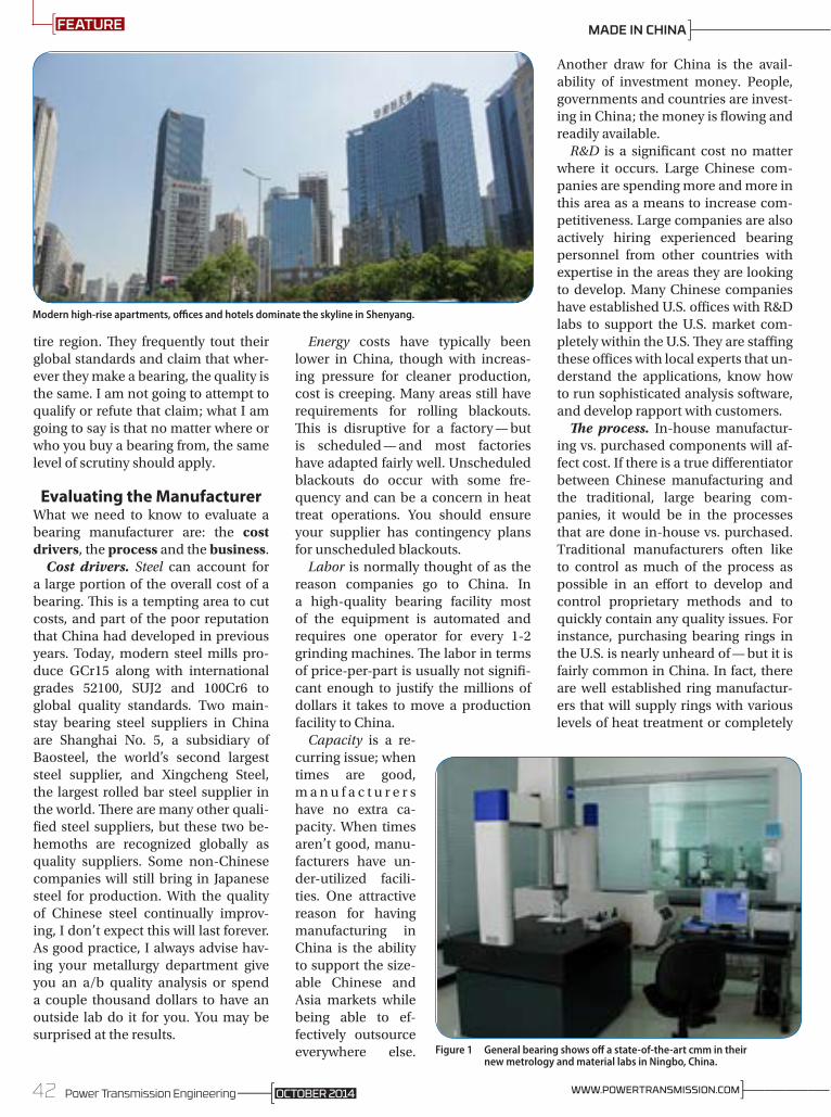
tire region. They frequently tout their global standards and claim that wher-ever they make a bearing, the quality is the same. I am not going to attempt to qualify or refute that claim; what I am going to say is that no matter where or who you buy a bearing from, the same level of scrutiny should apply.
Evaluating the ManufacturerWhat we need to know to evaluate a bearing manufacturer are: the cost drivers, the process and the business.
Cost drivers. Steel can account for a large portion of the overall cost of a bearing. This is a tempting area to cut costs, and part of the poor reputation that China had developed in previous years. Today, modern steel mills pro-duce GCr15 along with international grades 52100, SUJ2 and 100Cr6 to global quality standards. Two main-stay bearing steel suppliers in China are Shanghai No. 5, a subsidiary of Baosteel, the world’s second largest steel supplier, and Xingcheng Steel, the largest rolled bar steel supplier in the world. There are many other quali-fied steel suppliers, but these two be-hemoths are recognized globally as quality suppliers. Some non-Chinese companies will still bring in Japanese steel for production. With the quality of Chinese steel continually improv-ing, I don’t expect this will last forever. As good practice, I always advise hav-ing your metallurgy department give you an a/b quality analysis or spend a couple thousand dollars to have an outside lab do it for you. You may be surprised at the results.
Energy costs have typically been lower in China, though with increas-ing pressure for cleaner production, cost is creeping. Many areas still have requirements for rolling blackouts. This is disruptive for a factory — but is scheduled — and most factories have adapted fairly well. Unscheduled blackouts do occur with some fre-quency and can be a concern in heat treat operations. You should ensure your supplier has contingency plans for unscheduled blackouts.
Labor is normally thought of as the reason companies go to China. In a high-quality bearing facility most of the equipment is automated and requires one operator for every 1-2 grinding machines. The labor in terms of price-per-part is usually not signifi-cant enough to justify the millions of dollars it takes to move a production facility to China.
Capacity is a re-curring issue; when times are good, m a n u f a c t u r e r s have no extra ca-pacity. When times aren’t good, manu-facturers have un-der-utilized facili-ties. One attractive reason for having manufacturing in China is the ability to support the size-able Chinese and Asia markets while being able to ef-fectively outsource everywhere else.
Another draw for China is the avail-ability of investment money. People, governments and countries are invest-ing in China; the money is flowing and readily available.
R&D is a significant cost no matter where it occurs. Large Chinese com-panies are spending more and more in this area as a means to increase com-petitiveness. Large companies are also actively hiring experienced bearing personnel from other countries with expertise in the areas they are looking to develop. Many Chinese companies have established U.S. offices with R&D labs to support the U.S. market com-pletely within the U.S. They are staffing these offices with local experts that un-derstand the applications, know how to run sophisticated analysis software, and develop rapport with customers.
The process. In-house manufactur-ing vs. purchased components will af-fect cost. If there is a true differentiator between Chinese manufacturing and the traditional, large bearing com-panies, it would be in the processes that are done in-house vs. purchased. Traditional manufacturers often like to control as much of the process as possible in an effort to develop and control proprietary methods and to quickly contain any quality issues. For instance, purchasing bearing rings in the U.S. is nearly unheard of — but it is fairly common in China. In fact, there are well established ring manufactur-ers that will supply rings with various levels of heat treatment or completely
Modern high-rise apartments, offices and hotels dominate the skyline in Shenyang.
Figure 1 General bearing shows off a state-of-the-art cmm in their new metrology and material labs in Ningbo, China.
42 Power Transmission Engineering ]————WWW.POWERTRANSMISSION.COMOCTOBER 2014
FEATURE MADE IN CHINA

green. This is a different model than we are used to, but is working for many companies. If the supply base is well controlled and managed by the par-ent company and all of the compo-nents have traceability back to the bar stock it started with, it becomes more difficult to quantify the added risk. Many of the top 10 bearing companies regularly purchase components from well-known Chinese bearings suppli-ers, though usually not for high-per-formance parts. This goes right back to the scrutiny argument that one should know where every component of a bearing is coming from. One should treat every component in a bearing as a stand-alone part that falls under the same level of quality control as any other part; inner ring, outer ring, cage, rollers. These sub-component suppli-ers are still your suppliers. Good qual-ity manufacturers will welcome and encourage a visit to their suppliers.
Forging is substantially more expen-sive than simply turning bar stock into a bearing race, but anything with high-performance demands must be pro-duced with a forged billet for fatigue and strength properties.
For lightly loaded ball bearing ap-plications, or for small ball bearings, turned bar stock is frequently used in lieu of forging. The cost of modern high-speed forging equipment can be the barrier to competing in higher quality/volume markets for many smaller companies. Modern, horizon-tal forgers turn rolled bar into bear-
ing cones and cups at sewing machine speeds.
Finish grinding operations are the heart of bearing manufacturing. In h i g h -p ro d u c t i o n finish grinding a se-ries of grinders are set up in sequence with automated transfer lines be-tween each ma-chine. Each grinder will have an opera-tor that may cover 2-3 machines who pulls parts for in-
spection and logs measurements on a schedule, making machine adjust-ments as needed. This is the area to really focus on to assess the ability of the company to be able to produce millions of bearings a month within single digit microns of tolerance. Ide-ally, finish grind leads right into final assembly and the bearing will not need to be touched again until it is ready for packaging.
Honing tapered bearing raceways and large ribs is not a requirement to meet international bearing standards, but is most likely what you will receive with any of the top 6 global compa-nies — and even the top 3-4 Chinese companies. Honing is not cheap; it can require a multi-million dollar, dedicat-ed machine that also adds processing time, energy costs, floor space, opera-tors, maintenance and process con-
trols. Honing improves efficiency and wear properties for tapered bearings and noise levels for ball bearings, but generally does not affect durability. If the application is not sensitive to pre-load, torque or noise, honing may not be needed.
Final assembly can make or break your bearing quality, and thus should be fully automated — with minimal human involvement. Clean room as-sembly is becoming more common-place, either in a dedicated room or machinery that is completely enclosed creating an effective clean environ-ment. Set up correctly, final assembly is the process than can catch most things that went wrong upstream out-side of steel quality. There should be redundant checks for mass, height measurement, torque, noise, vibra-tion, roller count and orientation along with 2-3 wash stations. Often, smaller companies will try to forego expen-sive, automated machines in favor of cheap manual labor. This is not accept-able for high-quality and high-volume parts, but can be suitable for very large industrial bearings or low-volume, custom parts. Regardless — redundant quality checks should be in place.
The business. Local support is obvi-ously not free, but many foreign com-panies have learned that this is not an area to try and skimp on. Local support can be a huge benefit when develop-ing new products, quickly evaluating issues and consulting for general tech-nical support. Local support usually means experienced personnel that will answer calls and emails on the spot, be
Rich Oblizajek and Rick Peterson of C&U in their new metrology lab in Plymouth, MI.
Figure 2 Hatebur amp 70 high-speed forge general bearing state-of-the-art grinding lines.
43Power Transmission EngineeringOCTOBER 2014
FEATURE
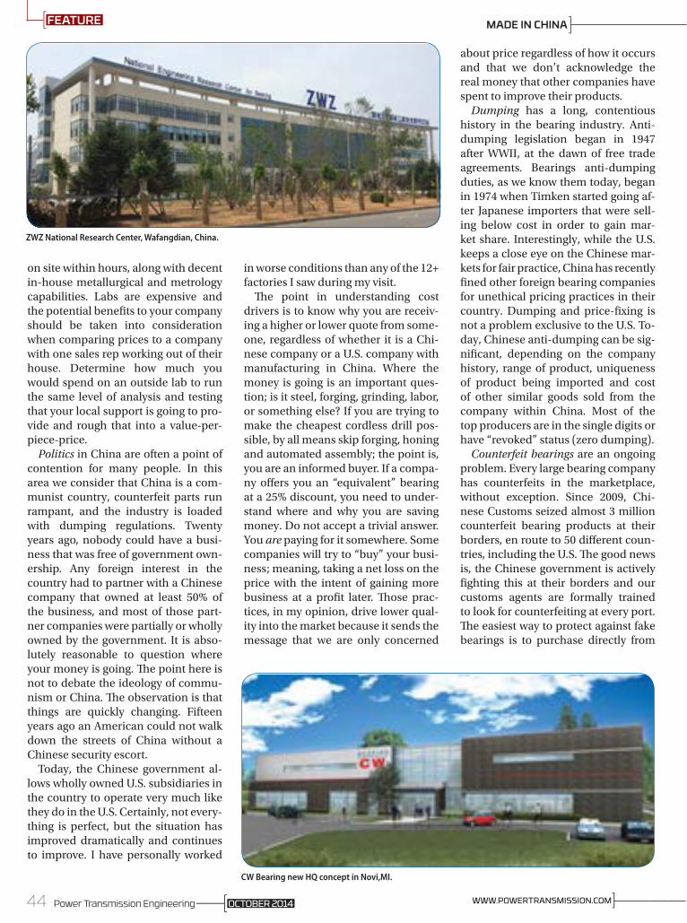
on site within hours, along with decent in-house metallurgical and metrology capabilities. Labs are expensive and the potential benefits to your company should be taken into consideration when comparing prices to a company with one sales rep working out of their house. Determine how much you would spend on an outside lab to run the same level of analysis and testing that your local support is going to pro-vide and rough that into a value-per-piece-price.
Politics in China are often a point of contention for many people. In this area we consider that China is a com-munist country, counterfeit parts run rampant, and the industry is loaded with dumping regulations. Twenty years ago, nobody could have a busi-ness that was free of government own-ership. Any foreign interest in the country had to partner with a Chinese company that owned at least 50% of the business, and most of those part-ner companies were partially or wholly owned by the government. It is abso-lutely reasonable to question where your money is going. The point here is not to debate the ideology of commu-nism or China. The observation is that things are quickly changing. Fifteen years ago an American could not walk down the streets of China without a Chinese security escort.
Today, the Chinese government al-lows wholly owned U.S. subsidiaries in the country to operate very much like they do in the U.S. Certainly, not every-thing is perfect, but the situation has improved dramatically and continues to improve. I have personally worked
in worse conditions than any of the 12+ factories I saw during my visit.
The point in understanding cost drivers is to know why you are receiv-ing a higher or lower quote from some-one, regardless of whether it is a Chi-nese company or a U.S. company with manufacturing in China. Where the money is going is an important ques-tion; is it steel, forging, grinding, labor, or something else? If you are trying to make the cheapest cordless drill pos-sible, by all means skip forging, honing and automated assembly; the point is, you are an informed buyer. If a compa-ny offers you an “equivalent” bearing at a 25% discount, you need to under-stand where and why you are saving money. Do not accept a trivial answer. You are paying for it somewhere. Some companies will try to “buy” your busi-ness; meaning, taking a net loss on the price with the intent of gaining more business at a profit later. Those prac-tices, in my opinion, drive lower qual-ity into the market because it sends the message that we are only concerned
about price regardless of how it occurs and that we don’t acknowledge the real money that other companies have spent to improve their products.
Dumping has a long, contentious history in the bearing industry. Anti-dumping legislation began in 1947 after WWII, at the dawn of free trade agreements. Bearings anti-dumping duties, as we know them today, began in 1974 when Timken started going af-ter Japanese importers that were sell-ing below cost in order to gain mar-ket share. Interestingly, while the U.S. keeps a close eye on the Chinese mar-kets for fair practice, China has recently fined other foreign bearing companies for unethical pricing practices in their country. Dumping and price-fixing is not a problem exclusive to the U.S. To-day, Chinese anti-dumping can be sig-nificant, depending on the company history, range of product, uniqueness of product being imported and cost of other similar goods sold from the company within China. Most of the top producers are in the single digits or have “revoked” status (zero dumping).
Counterfeit bearings are an ongoing problem. Every large bearing company has counterfeits in the marketplace, without exception. Since 2009, Chi-nese Customs seized almost 3 million counterfeit bearing products at their borders, en route to 50 different coun-tries, including the U.S. The good news is, the Chinese government is actively fighting this at their borders and our customs agents are formally trained to look for counterfeiting at every port. The easiest way to protect against fake bearings is to purchase directly from
ZWZ National Research Center, Wafangdian, China.
CW Bearing new HQ concept in Novi,MI.
44 Power Transmission Engineering ]————WWW.POWERTRANSMISSION.COMOCTOBER 2014
FEATURE MADE IN CHINA

the manufacturer or from one of their approved distributors. It is highly dis-couraged to buy bearings on the same site where you can buy books or an-tiques. It is also not recommended to buy from a smaller bearing company claiming to carry other name brand parts.
Here is where things start getting difficult: in a country that is creeping up on 20 billion bearings a year, many are good quality — but many are not. Bearings just seem to be a magnet for cheap producers and counterfeiters because you can take 60-year-old ma-chinery with dirty steel and still pro-duce a bearing that looks like any other bearing. This problem is not unique to China; they just happen to have 20% of the world’s population, so the problem is proportionately larger there.
InvestmentSomething that may be surprising is the considerable investment that Chi-nese companies are today. This is both with U.S. personnel and capital going into high-quality production facilities for U.S. bearing export. Here are just a few highlights from Chinese suppli-er development in 2014. ZWZ breaks ground on a global automotive engi-neering center in Plymouth, MI while finishing a national research center for roller bearings in Wafangdian, China.
General Bearing, who has been recently purchased by SKF, is a U.S. company that has exclusive produc-tion in China and has dominated the U.S. semi-truck and trailer wheel bear-ing business. They continue to expand their global footprint with cutting edge technologies in logarithmic crowning and in-house roller manufacturing, along with their own newly designed individual roller inspection machines.
The C&U Group broke ground on a new industrial park in Wuhu, China, that covers 17 million square feet and will be home to 20 manufacturing plants, an R&D center, employee hous-ing, an inland freight terminal and a private school supporting underprivi-leged local children. CW is a privately owned firm in Ningbo China and is rapidly growing in the ball bearing di-vision while also breaking ground on a new R&D center located in Novi, Mi.
ConclusionThe size and growth of the Chinese market can be intimidating — by any definition. A conversation that really stuck with me during my visits was with a general manager of a facility I was visiting who was driving me across town. He said in 1988, China was pro-ducing around one-half million ve-hicles a year, while the U.S. was pro-ducing nearly 16 million. He said the notion that China could ever catch up to the U.S. just seemed like nonsense, fantasy talk. Last year they produced 22 million vehicles — many of them by U.S. or European auto manufacturers. The Chinese themselves are having trouble understanding how fast they are growing and what the future holds. I was surprised that, not unlike the U.S., many older people miss the old days. They say that everything is about money now; and that there is more to life (sound familiar?). Most Chinese revere American products. Our cars are considered the best. “Made in the USA” is always considered as good as it gets, regardless of the product. George Clooney and Brad Pitt can be seen on nearly every corner on a bill-board or digital screen, promoting ev-erything from Rolex watches to luxury cars. In some ways, it helps me to know that the people I’m doing business with genuinely like me and my coun-try — which is not always the case. In my mind, this massive industry and this massive country seem to be here for the long haul.
My job is not to like it or dislike it. My job is to simply understand it as well as I can and react in a way that makes the most sense with the best information I have at the time.
ResourcesZWZSpecial thanks to: Ryan Hesselink, Jason Sholy.www.zwzbearingusa.com
General Bearing Corp.Special thanks to: Gary Binienda, Rick Janssens.www.generalbearing.com
C&U AmericasSpecial thanks to: Rich Oblizajek, Rich Peterson.www.cubearing.com
CW BearingSpecial thanks to: Jay Click, Chris Keelean.www.cwbearing.com
PROMPK.RUprompk.ru/ntn-snr/index_indust_rus.htm
Bearing-News.comwww.bearing-news.com/china-produced-1-8-trillion-bearings-in-2012www.bearing-news.com/in-the-first-half-of-2012-china-produced-more-than-8-billion-bearings
Bloombergwww.bloomberg.com/news/2014-08-19/china-imposes-28-million-antitrust-fine-on-japan-s-nsk.html
Freedoniawww.freedoniagroup.com/World-Bearings.html
WBOC 16www.wboc.com/story/26325061/global-and-china-bearing-industry-size-2013-market-analysis-growth-trends-and-forecast-report-2016-marketresearchreportsbiz
Benzingawww.benzinga.com/pressreleases/14/08/p4792219/global-and-china-bearing-industry-size-2013-market-analysis-growth-tren
SKFwww.skf.com/group/investors/bearings-market
Baosteelwww.baosteel.com/group_en
Xincheng Special Steelwww.jyxc.com/en
CHINA
For Related Articles Search
at www.powertransmission.com
Norm Parker is the bearing technical specialist for the driveline division at General Motors LLC. Located onsite at the Milford (MI) Proving Grounds, he is regularly tasked with testing theoretical models in the real world, in real time. With his bachelor and master degrees in mechanical engineering from Oakland University (Rochester, Michigan), Parker has developed a keen interest in the academic, commercial and engineering aspects of the bearing industry. Prior to joining GM, he rose through the ranks of traditional bearing companies; by so doing he acquired invaluable experience in working with some of the largest customers — with the toughest applications and demands — on the planet. Parker plans to continue expanding his expertise and providing substantial personal contributions to bearing technology through metallurgy, design and processing.
45Power Transmission EngineeringOCTOBER 2014
FEATURE
http://www.bloomberg.com/news/2014-08-19/china-imposes-28-million-antitrust-fine-on-japan-s-nsk.html
http://www.bloomberg.com/news/2014-08-19/china-imposes-28-million-antitrust-fine-on-japan-s-nsk.html
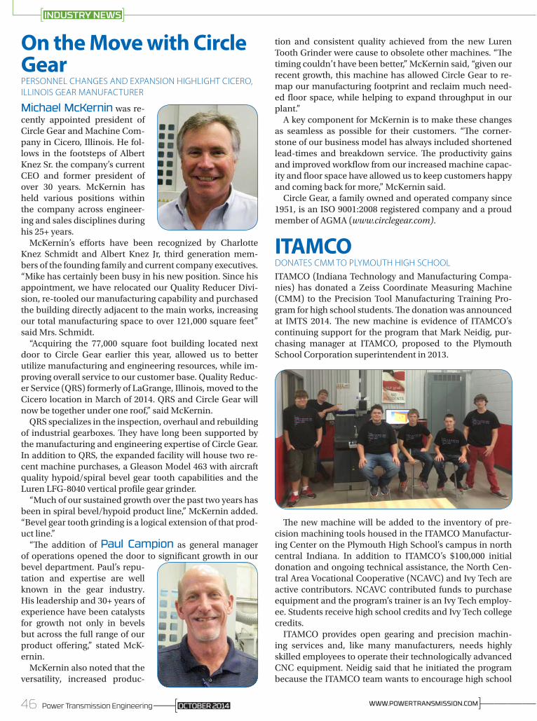
On the Move with Circle GearPERSONNEL CHANGES AND EXPANSION HIGHLIGHT CICERO, ILLINOIS GEAR MANUFACTURER
Michael McKernin was re-cently appointed president of Circle Gear and Machine Com-pany in Cicero, Illinois. He fol-lows in the footsteps of Albert Knez Sr. the company’s current CEO and former president of over 30 years. McKernin has held various positions within the company across engineer-ing and sales disciplines during his 25+ years.
McKernin’s efforts have been recognized by Charlotte Knez Schmidt and Albert Knez Jr, third generation mem-bers of the founding family and current company executives. “Mike has certainly been busy in his new position. Since his appointment, we have relocated our Quality Reducer Divi-sion, re-tooled our manufacturing capability and purchased the building directly adjacent to the main works, increasing our total manufacturing space to over 121,000 square feet” said Mrs. Schmidt.
“Acquiring the 77,000 square foot building located next door to Circle Gear earlier this year, allowed us to better utilize manufacturing and engineering resources, while im-proving overall service to our customer base. Quality Reduc-er Service (QRS) formerly of LaGrange, Illinois, moved to the Cicero location in March of 2014. QRS and Circle Gear will now be together under one roof,” said McKernin.
QRS specializes in the inspection, overhaul and rebuilding of industrial gearboxes. They have long been supported by the manufacturing and engineering expertise of Circle Gear. In addition to QRS, the expanded facility will house two re-cent machine purchases, a Gleason Model 463 with aircraft quality hypoid/spiral bevel gear tooth capabilities and the Luren LFG-8040 vertical profile gear grinder.
“Much of our sustained growth over the past two years has been in spiral bevel/hypoid product line,” McKernin added. “Bevel gear tooth grinding is a logical extension of that prod-uct line.”
“The addition of Paul Campion as general manager of operations opened the door to significant growth in our bevel department. Paul’s repu-tation and expertise are well known in the gear industry. His leadership and 30+ years of experience have been catalysts for growth not only in bevels but across the full range of our product offering,” stated McK-ernin.
McKernin also noted that the versatility, increased produc-
tion and consistent quality achieved from the new Luren Tooth Grinder were cause to obsolete other machines. “The timing couldn’t have been better,” McKernin said, “given our recent growth, this machine has allowed Circle Gear to re-map our manufacturing footprint and reclaim much need-ed floor space, while helping to expand throughput in our plant.”
A key component for McKernin is to make these changes as seamless as possible for their customers. “The corner-stone of our business model has always included shortened lead-times and breakdown service. The productivity gains and improved workflow from our increased machine capac-ity and floor space have allowed us to keep customers happy and coming back for more,” McKernin said.
Circle Gear, a family owned and operated company since 1951, is an ISO 9001:2008 registered company and a proud member of AGMA (www.circlegear.com).
ITAMCODONATES CMM TO PLYMOUTH HIGH SCHOOL
ITAMCO (Indiana Technology and Manufacturing Compa-nies) has donated a Zeiss Coordinate Measuring Machine (CMM) to the Precision Tool Manufacturing Training Pro-gram for high school students. The donation was announced at IMTS 2014. The new machine is evidence of ITAMCO’s continuing support for the program that Mark Neidig, pur-chasing manager at ITAMCO, proposed to the Plymouth School Corporation superintendent in 2013.
The new machine will be added to the inventory of pre-cision machining tools housed in the ITAMCO Manufactur-ing Center on the Plymouth High School’s campus in north central Indiana. In addition to ITAMCO’s $100,000 initial donation and ongoing technical assistance, the North Cen-tral Area Vocational Cooperative (NCAVC) and Ivy Tech are active contributors. NCAVC contributed funds to purchase equipment and the program’s trainer is an Ivy Tech employ-ee. Students receive high school credits and Ivy Tech college credits.
ITAMCO provides open gearing and precision machin-ing services and, like many manufacturers, needs highly skilled employees to operate their technologically advanced CNC equipment. Neidig said that he initiated the program because the ITAMCO team wants to encourage high school
46 Power Transmission Engineering ]————WWW.POWERTRANSMISSION.COMOCTOBER 2014
INDUSTRY NEWS

SUHNER Manufacturing Inc. · Rome, GA 30161Phone: 706-235-8046 · [email protected]
Flexible Shafts & Spiral Bevel GearsTwo different ways to transmit rotary motion.
ww
w.s
uhne
r.com
students to enter rewarding careers in manufacturing. “We need to keep the USA at the forefront of innovative manufac-turing, but we obviously have selfish motivations as well. We need skilled workers in our own facilities,” said Neidig.
The ITAMCO staff donated a Zeiss DuraMax CMM because it’s a world-class machine like the Zeiss CMM machines they use on their own shop floor. The DuraMax replaces the limi-tations of manual measuring tools with CNC accuracy and flexibility. “Our facility is better equipped than a typical ma-chine shop and we want participants in the training program to be prepared to work on a plant floor like ours,” said Neidig. Zeiss generously discounted the price of the machine, con-tributed 12 educational licenses for their Calypso software for the DuraMax, and provided training for the manufactur-ing center’s instructor. The Calypso software enables users to create a measuring plan without programming code or text editing.
After only one year of operation, the training program has success stories. Thirteen students have taken Precision Ma-chining I and four were seniors. Three of these seniors are now working at ITAMCO after graduation and one of the ITAMCO employees is continuing his education at Ivy Tech. The fourth student is also working for a local manufacturer. “The companies were pleased with our students’ training because they were prepared to work on the shop floor,” said Scott Kaser, the instructor for the Precision Tool Manufactur-ing Training Program and a certified CNC Machinist. “I was just like these kids. I didn’t want to go to college but I wanted a good paying job. I like working with them and I enjoy our partnerships with local companies that want to hire them,” he added.
AutomationDirectNAMED STEM FINALIST
The Technology Association of Georgia (TAG), the state’s leading association dedicated to the promotion and eco-nomic advancement of Georgia’s technology industry, re-cently announced that AutomationDirect has been named as a Finalist in the Corporate Outreach category for the 2014 STEM Education Awards.
47Power Transmission EngineeringOCTOBER 2014

TO WORK FOR YOU
GEAR DESIGN
PUTTING A LIFETIME
OF
EXPERIENCE
•Reverseengineering•Gearboxupgrades•Customgearboxdesign•Specificationdevelopment•Projectmanagement•Vendorqualification
•Designreviews•Bidevaluations•Toolingdesign•Customizedgeartraining•Equipmentevaluation•Custommachinedesign
Charles D. [email protected]
[630] 209-1652
www.beytagear.com
Looking for suppliers?Find all these and more at
www.powertransmission.com
The Technology Association of Georgia’s 3rd STEM Educa-tion Awards recognizes schools, programs, and companies for outstanding efforts and achievements in supporting and promoting STEM (Science, Technology, Engineering and Math) Education in Georgia.
For the past nine years, AutomationDirect has funded lo-cal competition robotics teams in Forsyth County and sur-rounding school systems (the “Forsyth Alliance”). Funding is primarily used to provide exciting STEM activities to all students in Forsyth County by ensuring there is at least one competition robotics team in every school and tournaments to compete in. Some schools now have over a dozen teams in multiple programs. Forsyth Alliance teams participate in lo-cal, state, national, and world competitions, including FIRST Lego League, FIRST Robotics, VEX, VEX IQ, BEST, Sea Perch and MATE.
“We have found there is no better way to get a young mind excited about STEM than to get them involved in a competi-tion robotics program,” says Rick Folea, senior training de-veloper at AutomationDirect. “The Alliance now supports over 100 teams in Forsyth County. The excitement of compe-tition drives their desire to learn in the classroom.” The rapid growth of this program and enrollment in STEM programs in the schools and creation of STEM academies in the schools is a testament to the incredible results of this initiative.”
“It is exciting to see the progress we are making with STEM education in Georgia. The increase in nominations each year and the quality of the nominations made it difficult for our judges,” said Michael Robertson, executive director of TAG Education Collaborative. “Congratulations to the Finalists! Your work engaging these students in STEM will benefit the students you touch for years to come with challenging and exciting careers.”
This year’s finalists were chosen in eight different catego-ries: elementary school, middle school, high school, post-secondary outreach, extracurricular program, STEM certi-fied School Outreach, Corporate Outreach, Best STEM Day Activity.
Winners in each category were officially honored at The 3rd Annual STEM Education Awards event held on Septem-ber 26th at the Savannah International Trade and Conven-tion Center in Savannah, Georgia. The event was presented by TAG, the TAG Education Collaborative (TAG-Ed), a non-profit 501c3 dedicated to advancing STEM education in Georgia, and TAG Savannah. “STEM occupations will in-crease in Georgia by more than 22,000 during the current decade,” said Tino Mantella, president & CEO of TAG. “The finalists of this year’s STEM Education Awards are helping to prepare the tech-ready workforce needed to fill these jobs and we applaud them for standing out as leaders in Georgia’s educational community.”
48 Power Transmission Engineering ]————WWW.POWERTRANSMISSION.COMOCTOBER 2014
INDUSTRY NEWS

ABBCOMPLETES CONSTRUCTION AND RENOVATION IN WISCONSIN
The cutting of ribbons at both ABB’s new office facility on Discovery Parkway in Wauwatosa, Wisconsin, and at the office/manufacturing site on Glendale Ave. in New Berlin, Wisconsin on Monday, August 25, marked completion of the buildings; construction and renovation of the sites began in April of 2013, and nearly all of the 725 employees that work at the ABB Southeastern Wisconsin sites were on hand to mark the occasion. “The business story of the multiple divisions represented at these sites is remarkable,” noted Greg Scheu,
region manager, NAM, in greeting employees. “Since 2001-2002, ABB has grown, here, to four times its size. This new office site and the complete renovation of the manufacturing site are a great statement about how the teams here work, of who you are – and how you are helping customers succeed. These buildings mark the beginning of the next chapter.” He noted that the new site at Discovery Parkway also “lifts the ABB brand image visibly in a town of fierce competitors.”
The new, white, three-story building at the Discovery site features large, lit ABB logos on all four sides, and sits on the highest promontory in Wauwatosa, noted Aaron Aleithe, the general manager and vice president of Drives and Controls, who was the master of ceremonies and profiled significant milestones achieved as the building construction/re-con-struction were underway. “We know that approximately 60,000 travelers pass the building daily on I-45, bringing a lot of recognition to our brand.”
Incredible Safety AchievementsHuntzinger, the general contractor who built the new site, logged 50,000 hours of construction with zero lost-time acci-dents, according to Aleithe. Meantime, at the manufacturing site, employees built more than 135,000 drives throughout the renovation, achieved a 98 percent on-time delivery re-cord, without any accidents. “It’s a testament to your work and dedication,” Ron Tucker, DM division manager, NAM, told attendees, “and I congratulate you on this achievement.”
49Power Transmission EngineeringOCTOBER 2014
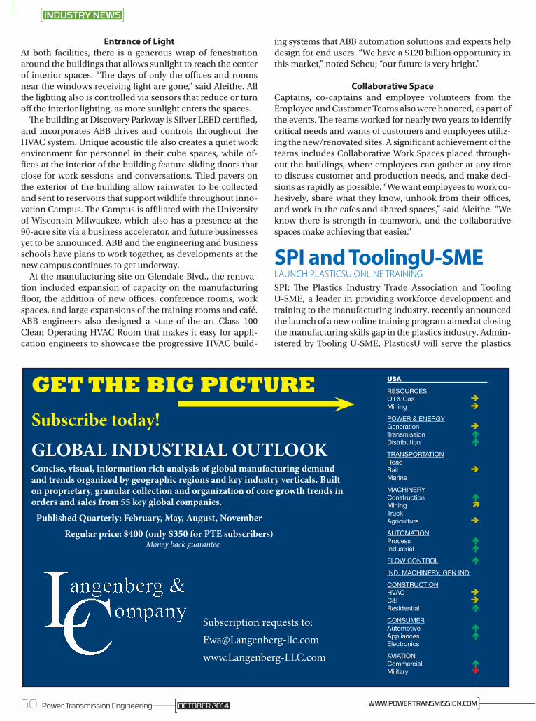
Entrance of LightAt both facilities, there is a generous wrap of fenestration around the buildings that allows sunlight to reach the center of interior spaces. “The days of only the offices and rooms near the windows receiving light are gone,” said Aleithe. All the lighting also is controlled via sensors that reduce or turn off the interior lighting, as more sunlight enters the spaces.
The building at Discovery Parkway is Silver LEED certified, and incorporates ABB drives and controls throughout the HVAC system. Unique acoustic tile also creates a quiet work environment for personnel in their cube spaces, while of-fices at the interior of the building feature sliding doors that close for work sessions and conversations. Tiled pavers on the exterior of the building allow rainwater to be collected and sent to reservoirs that support wildlife throughout Inno-vation Campus. The Campus is affiliated with the University of Wisconsin Milwaukee, which also has a presence at the 90-acre site via a business accelerator, and future businesses yet to be announced. ABB and the engineering and business schools have plans to work together, as developments at the new campus continues to get underway.
At the manufacturing site on Glendale Blvd., the renova-tion included expansion of capacity on the manufacturing floor, the addition of new offices, conference rooms, work spaces, and large expansions of the training rooms and café. ABB engineers also designed a state-of-the-art Class 100 Clean Operating HVAC Room that makes it easy for appli-cation engineers to showcase the progressive HVAC build-
ing systems that ABB automation solutions and experts help design for end users. “We have a $120 billion opportunity in this market,” noted Scheu; “our future is very bright.”
Collaborative SpaceCaptains, co-captains and employee volunteers from the Employee and Customer Teams also were honored, as part of the events. The teams worked for nearly two years to identify critical needs and wants of customers and employees utiliz-ing the new/renovated sites. A significant achievement of the teams includes Collaborative Work Spaces placed through-out the buildings, where employees can gather at any time to discuss customer and production needs, and make deci-sions as rapidly as possible. “We want employees to work co-hesively, share what they know, unhook from their offices, and work in the cafes and shared spaces,” said Aleithe. “We know there is strength in teamwork, and the collaborative spaces make achieving that easier.”
SPI and ToolingU-SMELAUNCH PLASTICSU ONLINE TRAINING
SPI: The Plastics Industry Trade Association and Tooling U-SME, a leader in providing workforce development and training to the manufacturing industry, recently announced the launch of a new online training program aimed at closing the manufacturing skills gap in the plastics industry. Admin-istered by Tooling U-SME, PlasticsU will serve the plastics
50 Power Transmission Engineering ]————WWW.POWERTRANSMISSION.COMOCTOBER 2014
INDUSTRY NEWS
GLOBAL INDUSTRIAL OUTLOOKConcise, visual, information rich analysis of global manufacturing demand and trends organized by geographic regions and key industry verticals. Built on proprietary, granular collection and organization of core growth trends in orders and sales from 55 key global companies.
Published Quarterly: February, May, August, November
Regular price: $400 (only $350 for PTE subscribers) Money back guarantee
GET THE BIG PICTURE
Subscribe today!
Subscription requests to:[email protected]
USA
RESOURCESOil & Gas èMining è
POWER & ENERGYGeneration èTransmission éDistribution é
TRANSPORTATIONRoad Rail èMarine
MACHINERYConstruction éMining ìTruck Agriculture è
AUTOMATIONProcess éIndustrial é
FLOW CONTROL é
IND. MACHINERY, GEN IND.
CONSTRUCTIONHVAC èC&I èResidential é
CONSUMERAutomotive éAppliances éElectronics
AVIATIONCommercial éMilitary ê

industry by providing formal online training tailored specifi-cally for the industry’s challenges and needs.
“Our industry has some of the best and brightest workers, operating top-of-the-line equipment and technology,” said SPI President and CEO William R. Carteaux. “Unfortunately, many of the technological advancements made recently are being held back by a growing manufacturing skills gap, which is why SPI partnered with Tooling U-SME to launch PlasticsU.”
“The plastics industry will not realize its full capacity for growth and production unless companies take an active ap-proach to workforce development. PlasticsU offers these com-panies flexibility and convenience to make this process easy.”
As recent as 2013, a vast majority of U.S. manufacturing companies reported being challenged by a moderate short-age of qualified workers for skilled production, as reported by SME. Volume alone is no longer the sole solution to in-creased productivity. Highly technical and specialized skills are required not only to meet increased demand, but to maintain growth into the future.
“By instituting a training program, companies can ensure they remain competitive today and into the future,” said Managing Director of Workforce and Education at SME, Jeannine Kunz. “Creating a well-trained workforce can help improve quality, cycle time, communications, reliability and safety, while reducing costs and downtime/rework.”
Because SPI represents and supports such a wide range of the companies throughout the entire plastics industry, it partnered with Tooling U-SME to develop PlasticsU and
provide a customized selection of courses and programs for areas specific to as many stakeholders as possible. With lev-els ranging from a basic introduction to the most advanced studies, courses include Interpreting Blueprints; Creating a Milling Program; Principles of Injection Molding; Measuring System Analysis; Rigging Inspection and Safety; and CNC Controls: GE Fanuc, Haas and Mazak.
Danfoss to Acquire VaconDenmark’s Danfoss A/S has bid $1.34 billion for the acquisi-tion of Finland’s Vacon Oy, which would result in the union of two of the ten largest variable frequency drive suppliers
globally. According to IHS, the combined low voltage drive revenue from the two companies represent over 10% of the global market value; this is slightly less than the estimated market shares for ABB and Siemens, the two largest suppli-ers of low voltage drives globally.
www.ExcelGear.com
•Completegeardesign,manufacturingandreverseengineeringservices
•Gearhobbing&grindingfrom1"–60"(ToAGMA15)
•Internalgeargrindingfrom10"–60"•Gearshapingto36"diameter(9"facewidth)
•Windturbinegearboxes,highspeedspindles,gimbalheadsandgearboxes
•Competitivepricesandqualitygeardesignandmanufacturingwithdeliverycommitmentsyoucancounton!
EXCEL GEAR, INC.GEARS 1"– 60" - AGMA 15
TheEXCELpromise;We'll excel where others fall short.
Introducing Excel-Lent Gear Design Softwareprovidingaccurategeardesignandanalysisthatcangetanyoneupandrunningfast–www.excel-lentsoftware.com
A TOTAL SERVICE COMPANYISO9001-2008APPROVED
51Power Transmission EngineeringOCTOBER 2014

CALENDAR
CTI SymposiumAutomotive Transmissions, HEV and EV Drives
13th International Plus: Transmission Expo
8–11 December 2014, BerlinGermany
Simultaneous Translation German EnglishEnglish Conference Documentation!
German programme available at
www.transmission-symposium.com
Panel discussionHow will the future drive system look like?
Experts in the PlenumBernhard MattesChairman | Ford-Werke GmbH
Prof. Helmut ListChairman and CEO | AVL List GmbH
Prof. Dr Herbert KohlerVice President Group Research and Sustainability andChief Environmental Offi cer | Daimler AG
Uwe WagnerSenior Vice President R&D Automotive | Member of the Management Board Automotive | Schaeffl er Technologies GmbH & Co. KG
Terry NakatsukaCEO | Jatco Ltd.
Dr Klaus BadenhausenVice President | Head of Chery Technical Center Shanghai | Chery Automobile Co., Ltd.
Prof. Dr Stefan PischingerDirector of the Institute for Combustion Engines | RWTH Aachen University | President and Chief Executive Offi cer | FEV GmbH
Prof. Dr Jens HadlerGeneral Manager | Automobil-Prüftechnik Landau GmbH
Dr Robert PlankChairman of the Board/CEO | TÜV NORD Mobilität GmbH & Co. KG
Enrico SedoniVice President Driveline Component Product Line | CNH Industrial
1,800 Delegates Worldwide in 2013 – The Largest TM & Drive Event Series
120 Exhibitors @ the Transmission Expo in Berlin
35 % International Participants
>20 Nationalities Meet @ CTI in Berlin
Home Of The World´s International Transmission & Drive Community
Prof. Dr Stefan Pischinger
Uwe WagnerProf. Dr Herbert Kohler
Dr Robert Plank
Prof. Helmut ListBernhard Mattes
Prof. Dr Jens HadlerTerry Nakatsuka Dr Klaus Badenhausen
Prof. Dr Ferit Küçükay
Enrico Sedoni
Chairman of the CTI Symposium:Prof. Dr Ferit KüçükayDirector | Institute of Automotive Engineering | Technical University of Braunschweig
Sponsors
P2300346_Anz_203,2x273mm_Gear Technology.indd 1 17.09.2014 10:07:31
October 22–24—ASME DSCC 2014. Mar-riott Plaza Hotel, San Antonio, Texas. The Dynamic Systems and Control Conference (DSCC) is the showcase technical forum of the Dynamic Systems and Control Division (DSCD). It provides a focused and intimate setting for dissemination and discussion of the state of the art in dynamic systems and control research, with a mechanical engineering flavor. The 2014 DSCC technical program will cover the modeling, simulation, analysis, design, and control of dynamical systems. Topics will include control theory, industrial applications, and innovations in dynamical systems and control educa-tion. Technical themes for the conference—including advanced manufacturing, renewable and traditional energy, bioengineering and biomedical engineering, and cybersecurity for critical infrastructure—will be featured in special tracks. The program will include contributed sessions, invited sessions, tutorial ses-sions, special sessions, workshops, and exhibits. For more information, visit www.asmeconferences.org.
October 22–25—PTDA 2014 Industry Summit. Orlando, Florida. Join more than 550 delegates for a networking event from the leading distribution and manufacturing companies involved in the PTDA. The summit includes educational workshops, networking forums, one-one-meetings, social events and an optional golf outing. Mike Ditka will give a keynote presentation on “Attitude, Character and Enthusiasm,” on Friday October 24.Alan Beaulieu will give a keynote address called “The Beaulieu Report” that provides an accurate and straightforward forecast of the PT market-place. For additional information, visit www.ptda.org.
October 27–30—PTC MDA ASIA. Shanghai New International Expo Center, Shanghai, China. As the largest annual industrial event in power transmis-sion and control in Asia and the second largest in the world, PTC includes themes of smart manufacturing, energy efficiency and environmental protection. The event will attract exhibitors from China, Germany, Italy, Korea, Turkey, Taiwan of China and other countries and regions. In the exhibition, the debut of new products will illustrate the integration and development of Industry 4.0, highlighting the utilization of eco-friendly materials. PTC ASIA 2014 is jointly organized by China Hydraulics Pneumatics & Seals Association, China General Machine Components Industry Association, Deutsche Messe AG and Hannover Milano Fairs Shanghai Ltd., which will share a total exhibition area of more than 80,000 sqm with ComVac ASIA 2014 that will be held during the same period. For more information, visit www.ptc-asia.com.
October 27–30—Gear Dynamics and Gear Noise Course. Ohio State University Cam-pus. The Gear Dynamics and Gear Noise Short Course has been offered for 35 years and is considered extremely valuable for gear designers and noise specialists who encounter gear noise and transmission design problems. Attendees will learn how to design gears to minimize the major excitations of gear noise: transmission error, dy-namic friction forces and shuttling forces. Fundamentals
of gear noise generation and gear noise measurement will be covered along with topics on gear rattle, transmis-sion dynamics and housing acoustics. This four-day course includes extensive demonstrations of specialized gear analysis software in addition to the demonstrations of many Ohio State gear test rigs. A unique feature of the course is the interactive workshop session (on Day 3) that invites attendees to discuss their specific gear and transmission noise concerns. The round table discussions on Day 4 are intended to foster interactive problem solving discussions on a variety of topics. Cost is $1,950 per person. For more information, visit www.nvhgear.org.
November 2–5—Pack Expo Interna-tional 2014. Chicago, Illinois. Decision makers from a broad range of industries come to Pack Expo Inter-national for the opportunity to talk shop with vendors and “think outside the plant.” Corporate managers, engineers, sales managers, plant managers, manufactur-ers and production supervisors, brand and marketing managers, quality controllers, purchasers, research/development and package designers from across the U.S. and around the world find value in learning where their companies stand on the technology curve and how they can provide flexible options for their customers. For more information, visit www.packexpointernational.com.
November 14–20—ASME 2014 IMECE. Montreal, Quebec. The annual ASME International Mechanical Engineering Congress and Exposition (IMECE) is the premier global conference that focuses on today’s technical challenges, research updates and breakthrough innovations that are shaping the future of engineering. The Congress convenes engineers, academics, scientists and technologists of all disciplines for the purposes of exploring solutions to global challenges and for the advancement of engineering excellence worldwide. Engineers have long contributed to human progress by solving complex challenges on a global scale. Many of these challenges are found in developing and emerging markets, particularly as they relate to critical infrastructures, such as access to energy, clean water, effective sanitation and healthcare. For more information, visit www.asmeconfernces.org.
November 19–20—Design and Manu-facturing Montreal. Montreal, Quebec. Design and Manufacturing presents a variety of manufacturing technologies, products and services including rapid protyping, engineering, electronics, automation, lasers, motors/drives, packaging, materials, quality systems and a full range of contract services. Attendees can speak with suppliers, compare products and see the latest developments in several key manufacturing sectors. The show is co-located with PackEx, Automation Technology Expo, AeroCon, Contract Manufacturing, Sustainability and more. One badge gets you access to every trade show. Exhibitors include ABB Canada, Aerotech Inc., Bosch Rexroth Canada, Eaton, SEW-Eurodrive and others. The Innovation Briefs Theater will offer scheduled presentations located right in the resource hall. For more information, visit www.canontradeshows.com.
52 Power Transmission Engineering ]————WWW.POWERTRANSMISSION.COMOCTOBER 2014

CTI SymposiumAutomotive Transmissions, HEV and EV Drives
13th International Plus: Transmission Expo
8–11 December 2014, BerlinGermany
Simultaneous Translation German EnglishEnglish Conference Documentation!
German programme available at
www.transmission-symposium.com
Panel discussionHow will the future drive system look like?
Experts in the PlenumBernhard MattesChairman | Ford-Werke GmbH
Prof. Helmut ListChairman and CEO | AVL List GmbH
Prof. Dr Herbert KohlerVice President Group Research and Sustainability andChief Environmental Offi cer | Daimler AG
Uwe WagnerSenior Vice President R&D Automotive | Member of the Management Board Automotive | Schaeffl er Technologies GmbH & Co. KG
Terry NakatsukaCEO | Jatco Ltd.
Dr Klaus BadenhausenVice President | Head of Chery Technical Center Shanghai | Chery Automobile Co., Ltd.
Prof. Dr Stefan PischingerDirector of the Institute for Combustion Engines | RWTH Aachen University | President and Chief Executive Offi cer | FEV GmbH
Prof. Dr Jens HadlerGeneral Manager | Automobil-Prüftechnik Landau GmbH
Dr Robert PlankChairman of the Board/CEO | TÜV NORD Mobilität GmbH & Co. KG
Enrico SedoniVice President Driveline Component Product Line | CNH Industrial
1,800 Delegates Worldwide in 2013 – The Largest TM & Drive Event Series
120 Exhibitors @ the Transmission Expo in Berlin
35 % International Participants
>20 Nationalities Meet @ CTI in Berlin
Home Of The World´s International Transmission & Drive Community
Prof. Dr Stefan Pischinger
Uwe WagnerProf. Dr Herbert Kohler
Dr Robert Plank
Prof. Helmut ListBernhard Mattes
Prof. Dr Jens HadlerTerry Nakatsuka Dr Klaus Badenhausen
Prof. Dr Ferit Küçükay
Enrico Sedoni
Chairman of the CTI Symposium:Prof. Dr Ferit KüçükayDirector | Institute of Automotive Engineering | Technical University of Braunschweig
Sponsors
P2300346_Anz_203,2x273mm_Gear Technology.indd 1 17.09.2014 10:07:31
CALL FOR PAPERS!Are you sitting on an idea for a technical paper but wondering where to present it? Do you have one already written, sitting on your desk, gathering machine dust?
How about Power Transmission Engineering? We are always looking for gearing- and power transmission component-relevant technical papers for publication in the magazine and in its digital version. Having your work appear in Power Transmission Engineering guarantees you an audience of the most experienced and discriminating industry players. You say your work has not been peer-reviewed? Not a problem, as we are lucky—and thankful—to have on-hand some of the most experienced
and brilliant minds in the industry—our technical editors. So if your work “passes muster” and is published, you’ll know you were reviewed by the best—and most demanding.
Chances are you’ll be creating the paper under the auspices of the company for whom you work or own, or for one of the various industry-relevant associations. That means they as well will bask in the reflected glory that accrues with publication in Power Transmission Engineering.
For publication guidelines and more information, please contact Jack McGuinn at [email protected].
Arrow GearPage 5www.arrowgear.com
Automation DirectInside Front Coverwww.automationdirect.com
B&R Machine and GearPage 7www.brgear.com
BaldorPage 21www.baldor.com
Beyta Gear ServicePage 48www.beytagear.com
Brevini GearPage 16brevinigear.com
C&U AmericasPage 29www.cubearing.com
Cabat Inc.Page 2www.cabatinc.com
Circle GearPage 17www.circlegear.com
Cone DrivePage 26www.condedrive.com
CTI – Car Training InstitutePage 53www.transmission-symposium.com
Diequa Corp.Page 22www.diequa.com
Electro Static TechnologyPage 12www.est-aegis.com/handbook
Elgin Fastener GroupPage 14elginfasteners.com
Excel GearPage 51www.excelgear.com
First GearPage 11www.first-gear.com
Forest City GearPage 13www.forestcitygear.com
J.W. WincoPage 2www.jwwinco.com
Lafert North AmericaPage 25www.lafertna.com
Langenberg & Co.Page 50www.langenberg-llc.com
LubriplatePage 27www.lubriplate.com
McInnes Rolled RingsPage 28www.mcinnesrolledrings.com
Motion IndustriesPage 23www.motionindustries.com
Napoleon Engineering ServicesPage 31www.nesbearings.com
NSK AmericasPage 19www.nskamericas.com/aip
QA1 Precision ProductsPage 47www.qa1.net/industrial
R+W AmericaPage 10www.rw-america.com
Schaeffler GroupPage 9www.schaeffler.us
SEW-EurodriveInside Back Coverwww.seweurodrive.com
SKFPage 3www.skf.com
Smalley Steel Ring Co.Page 15www.smalley.com
Stock Drive Products/Sterling InstrumentOutside Back Coverwww.sdp-si.com
Suhner Manufacturing Inc.Page 55www.suhner.com
WD Bearing AmericaPage 57www.wd-bearing.com
Yaskawa America Inc.Page 33www.yaskawa.com
54 Power Transmission Engineering ]————WWW.POWERTRANSMISSION.COMOCTOBER 2014
ADVERTISING INDEX

FREE SUBSCRIPTION
Power Transmission Engineering is Your KEY to understanding Gears,
Gear Drives, Bearings, Motors, Clutches, Couplings, Brakes, and other Power
Transmission Components.
Unlock your FREE subscription by filling out this form.
Company Name: _________________________________________________________
Address: _______________________________________________________________
_______________________________________________________________________
_______________________________________________________________________
City: ___________________________________________________________________
State/Province: _________________________ ZIP/Postal Code: __________________
Country: _______________________________________________________________
Telephone: ___________________________Fax: ______________________________
E-mail: ________________________________________________________________
Website: _______________________________________________________________
(print)
WE MAKE power transmission products (10) WE BUY power transmission products (12) WE SELL power transmission products (Distributors, sales reps. etc.) (14) WE DESIGN products with power transmission components in them. (16) Other (please describe) (15)____________________________________
How is THIS LOCATION involved with power transmission products? (Check all that apply)
FAX TO 1-847-437-6618 orVISIT US ONLINE AT
www.powertransmission.com/subscribe.htm
❏ YES, I want to be notified each issue when Power Transmission Engineering is available online
❏ YES, I would like to receive Power Transmission Engineering’s monthly e-mail newsletter
❏ YES, I would like to receive Power Transmission Engineering’s twice monthly e-mail Product Alerts
❏ YES, I would like to receive 3rd-party e-mails from Power Transmission Engineering’s advertisers and partners
❏ YES, I would like to receive subscription renewal notices by e-mail
❏ No, I do not wish to be contacted by e-mail.
(So we can notify you when the online edition is available)SAVE a TREE!
I ONLY want the digital edition (e-mail required)
DIGITAL SUBSCRIPTIONS
1
YES I want to receive/continue to receive Power Transmission Engineering FREE!
No thank you.
Name:_________________________________________JobTitle/Position: ___________________________
Signature _____________________________________________________ Date: ______________________
2 E-mail ___________________________________________________________
3 Please update your contact information orattach you business cards here. (No Staples)
4
(required)
❏ Corporate Management (1❏ Plant Engineering (2)❏ Design Engineering (3)❏ Marketing & Sales (4)❏ Manufacturing Engineering (5)❏ Purchasing (6)
❏ Quality Control (7)❏ Factory Automation (8)❏ Maintenance (9)❏ Other (10) _____________________________
5 What is your primary job function responsibility? (Check one)
Is there a colleague within your company that might benefit from having their own copy of Power Transmission magazine?Name: ________________________________________________
Title: _________________________________________________

“ You see, Tom, the world goes on at a smarter pace now than it did when I was a young fellow. It’s this steam, you see.”
Mr. Deane to Tom Tulliver — George Eliot’s The Mill on the Floss
Heaven help Mr. Deane were he around today.
In our non-stop world of transporta-tion & transport technology, for at least the past decade it is without question the electric car that has drawn most of the attention — from Detroit to Wall Street to Main Street. And whether that attention concerns the successes and failures to date of electric engines, bat-tery-charging stations or the promised CO2 reduction — personal-use, elec-tric-powered automobiles (barring a late-inning comeback by nuclear-pow-ered) are seemingly the future of “get-ting around.”
When “the future” will actually show up is pure guesswork.
Case in point — coming one day to an airport near you are — the future of electric-powered airplanes.
A recent event in support of that future, and the consensus highlight of longtime French airplane builder Airbus Group’s (with Aero Compos-ite Saintonge participation) E-Aircraft Day — was celebrated this past April at Aéroport de Bordeaux-Mérignac, France. The company’s “E-Fan” ex-perimental aircraft performed with-out incident for its inaugural public exhibition flight, wowing a sizeable crowd — including no less than French Minister of Industry Arnaud Monte-bourg. Essentially a “training” craft, the E-Fan — of all-composite, energy-saving construction — also serves as a, well — sales demo.
As what might be an indication of how nascent this technology re-mains — or more to the point, its com-mercialization — you’ll find scant technical information online about the E-Fan’s electric engine. But, why quibble — this is Power Play, not the U.S. Patent Office.
The bird is “skippered” by — e-FADEC — e-FADEC? — try rolling that off the tongue — an integrated energy management system that interfaces seamlessly with all the craft’s electri-cal features, in turn optimizing system monitoring and control.
So in fact how far along are we with electric air travel? Consider how long the electric car and its consumer ac-ceptance and full commercialization are taking. A couple of factoids provide some perspective, courtesy Wikipedia. In 1883, Gaston Tissandier (a balloon-ist) was the first to use electric motors in airship propulsion. (Unintended product placement here): Tissandier fit a Siemens electric motor to a bal-loon and, voilla — the first — techni-cally — electric-powered flight.
Electric motors have been used for model fixed-wing aircraft (those are toys, for God’s sake) since at least 1957, with a challenged claim from 1909.
The point being, apparently the con-cept for electric aircraft is anything but novel. Aviators have been strapping electric motors on their balloons and dirigibles for near 150 years.
Yes, these things take time, as AirBus (and Boeing, to name just one seri-ous competitor) is well aware — and in some cases require the courage of one’s convictions on the part of the inventor.
Consider inventor / entrepreneur Robert Fulton; we learned about him in high school history. Remember “Fulton’s Folly?” What he considered his state-of-the-art steamboat and his business plans for it were a general laughingstock before the vessel had even left the dock. Fulton had the last laugh — all the way to the bank. “Ful-ton’s Folly” is credited as “the first ves-sel to demonstrate the viability of using steam propulsion for commercial river transportation.”
Sometimes, things don’t turn out so happily — even when you have the science on your side. Consider Nikola Tesla (whom, alas, we didn’t learn about in high school — not U.S.
high-schools), the mercurial, brilliant Serbian-American inventor, electri-cal engineer, mechanical engineer, and futurist. His research was instru-mental in the development of the AC (alternating current) motor, a technol-ogy thought impossible by physicists at the time. But were you aware that the beloved Spencer Tracy — Thomas Edison — inventor of the direct cur-rent (DC) — did everything possible to discredit Tesla’s superior alternating current system — including electrocut-ing an elephant with Tesla’s system to portray it as dangerous? Somehow, successful attacks like this eventu-ally led to Tesla’s bitter dissipation and death — a penniless laughingstock. To-day, of course, every wall outlet in the world outputs AC power, and Tesla’s eccentric research is regarded as pio-neering in electromagnetism (and an electric car company bears his name).
And just one more object lesson be-fore we go — the Wright Brothers. After Kitty Hawk, the Bros regularly dem-onstrated their “airship” capabilities over a field in Dayton, Ohio for nearly a year. U.S. officials — Cabinet or oth-erwise — never once showed up to observe, discuss, or collaborate. Sci-entific American magazine, for its part, published stories about “The Lying Brothers.” The Dayton dailies played hands-off as well, never once sending a reporter.
Finally tired of being treated as if they had invented leprosy — not avia-tion — the boys fled to Europe, where of course they were enthusiastically embraced. As were the aircraft con-tracts they had to sell to the French, Germans, and Brits.
Chariots to Steamboats to E-Fans:The Next Way Around Just Waiting to Be Invented
56 Power Transmission Engineering ]————WWW.POWERTRANSMISSION.COMOCTOBER 2014
POWER PLAY
movigear.com / 864-439-7537
Although independent research has proven that MOVIGEAR® from
SEW-EURODRIVE reduces startup and operating costs by 20-30%,
actual case studies show that many users are experiencing 50% or
more. MOVIGEAR® also substantially reduces your inventory via its
unique ability to replace several gear units of different ratios with a
single unit. Yes...less really is more!