Ocean Energy Technology Study - Forside / Folketinget...It is recommended that within Europe, the...
67
2012 Ocean Energy Technology Study Alliancen for Grøn Offshore Energi The Alliance for Offshore Renewables Prepared by DanWEC Author: Kim Nielsen 10 May 2012 Klima-, Energi- og Bygningsudvalget 2011-12 KEB alm. del Bilag 358 Offentligt
Transcript of Ocean Energy Technology Study - Forside / Folketinget...It is recommended that within Europe, the...

2012
Ocean Energy Technology Study
Alliancen for Grøn Offshore Energi The Alliance for Offshore Renewables
Prepared by DanWEC Author: Kim Nielsen
10 May 2012
Klima-, Energi- og Bygningsudvalget 2011-12KEB alm. del Bilag 358Offentligt

Ocean Energy Technology Study, DanWEC 2012, revision 10-09-2012
ii Ocean Energy Technology Study
Ocean Energy Technology Study, DanWEC 2012, revision 10-09-2012
iii Ocean Energy Technology Study
DanWEC Danish Wave Energy Center
Technical Report No. 1
Ocean Energy Technology Study
2012
Suggested Citation:
Nielsen K. 2012. Ocean Energy Technology Study.
DanWEC; Technical Report No.1 for The Alliance for Offshore Renewables.
DanWEC Sekretariat
Andy Jensen, Specialkonsulent
c/o Thisted Kommune
Asylgade 30
7700 Thisted
Tlf: 21 76 23 32
Mail: [email protected]
www.danwec.com
CVR-nr.: 33067348

Ocean Energy Technology Study, DanWEC 2012, revision 10-09-2012
iv Ocean Energy Technology Study
Preface This study has been realized through funding from the Danish Council for
Strategic Research’s funding scheme “Funding of EU Networks”.
The study has been initiated by the partners of the project “Network for
improving Danish participation and access to EU-funding within the sphere of
Renewable Offshore Energy.” The following partners are included in the project
consortium:
Offshore Centre Denmark
Lindø Offshore Renewables Centre
Technical University of Denmark
Aalborg University
South Denmark EU Office
DanWEC has been contracted to carry out the study, using subcontractor
consultant Kim Nielsen, Denmark, as lead author and principal investigator.
Erik Friis-Madsen, Löwenmark, Denmark, has contributed to this study by going
through and provided a valuable database of available existing Danish and
international ocean energy technology studies to the analysis of the most
promising technologies of Ocean Energy systems, as well as providing a
constructive review of this report.
The informative and inspiring feedback to questionnaires from WEC developers,
Utilities, Universities and DNV is gratefully acknowledged.
Andy Jensen, Specialkonsulent
Forord (in Danish) Dette studie er udført med støtte fra Det Strategiske Forskningsråd i Danmark
under ordningen “"Netværksmidler til styrkelse af dansk deltagelse i EU-
satsninger inden for forskning og udvikling"”. Studiet er initieret af partnerne i
projektet ” Netværk som kan øge dansk deltagelse og tilgang til EU-funding
indenfor vedvarende off-shore energi”. Følgende partnere er med i konsortiet:
Offshore Center Danmark
Lindoe Offshore Renewables Center (LORC)
DTU, Danmarks Tekniske Universitet
Aalborg Universitet
Det Syddanske EU-Kontor
DanWEC vandt kontrakten til at udføre studiet med bølgeenergikonsulent Kim
Nielsen, Denmark, som underleverandør og hovedforfatter.
Erik Friis-Madsen, Löwenmark, Danmark har bidraget til studiet ved at gennemgå
og stille en værdifuld database over eksisterende litteraturstudier vedr. dansk og
internationale bølge og tidevands projekter til rådighed og dertil bidraget med
konstruktiv kritik af nærværende rapport.
Endelig rettes en varm tak til den til de udviklere, el-selskaber, universiteter og
DNV som har svaret på spørgeskemaer og bidraget via interviews.
Andy Jensen, Specialkonsulent
Content: 1 Introduction ................................................................................................ 1
2 Scope ......................................................................................................... 1
3 Summary and conclusions ............................................................................. 2
4 Indledning, sammenfatning og konklusioner (in Danish) ................................... 3
5 Ocean Energy .............................................................................................. 5
5.1 The Oceans Energy Sources .................................................................... 5
6 Prioritizing funding in the area of Ocean Energy ............................................... 6
6.1 Research & Development ....................................................................... 8
6.2 Market stimulation ................................................................................. 9
6.3 Planning issues in different countries ....................................................... 9
6.4 Optimisation and learning ....................................................................... 9
7 Reviews of studies of the most promising technologies .................................... 10
7.1 Recommendation ................................................................................. 11
8 The status and potential of the ocean energy sector ........................................ 12
8.1 Status in selected countries ................................................................... 13
9 Challenges for selected Wave Energy Technologies ......................................... 22
9.1 Shore and Near-shore Bottom Standing Devices....................................... 23
9.2 Offshore tight-moored .......................................................................... 26
9.3 Offshore slack moored devices ............................................................... 28
9.4 Combined solutions: ............................................................................. 34
9.5 Common challenges for selected Wave Energy technologies....................... 35
10 The industry, subcontracting industry and universities ................................. 36
11 International market trends within the Ocean Energy ................................... 38
11.1 The technology trends .......................................................................... 38
11.2 Implementing Agreement on Ocean Energy Systems (OES) ....................... 39
11.3 Maritime Spatial Planning ...................................................................... 39
11.4 Standards under IEC TC 114 .................................................................. 40
11.5 Certification of Tidal and Wave Energy Converters .................................... 40
11.6 The EERA initiative ............................................................................... 40
11.7 European projects on Ocean Energy ....................................................... 41
12 Selected examples of cooperation and synergies ......................................... 43
12.1 European Wavetrain 2 Project ................................................................ 43
12.2 Float 2 Case story: ............................................................................... 44
13 Information exchange .............................................................................. 45
12.1 Utilities ............................................................................................... 46
12.2 Universities ......................................................................................... 49
12.3 Standardisation / certifying authorities .................................................... 51
Appendix I Sources of Ocean Energy ................................................................... 52
Appendix II Ocean Energy Road Map ................................................................... 57
References....................................................................................................... 58
Ocean Energy Technology Study, DanWEC 2012, revision 10-09-2012
Ocean Energy Technology Study 1
1 Introduction
The interest and support for Ocean Energy is confirmed as shown by the news
concerning government policies in Denmark, UK, France, Spain and Portugal with
regards to Wave and Tidal energy.
On Thursday 22nd March 2012, the Danish Government and the opposition entered an
agreement on the Danish energy policy for 2012-2020. With the political initiatives in
the agreement, the CO2 emission in 2020 will be 34% less than in 1990 and energy
consumption will be reduced by 12%. Approximately, 35% of the energy will come
from renewable resources.
As part of this agreement, DKK100 million is allocated to promote development and
use of new renewable electricity production technologies, as well as DKK25 million
specifically for wave energy.
On 5th April 2012, the UK Government launched its eagerly awaited £20 million
Marine Energy Array Demonstrator scheme (MEAD). This scheme will support up to 2
pre-commercial projects to demonstrate the operation of wave and/or tidal devices in
array formation over a period of time.
The UK Energy and Climate Change Minister Greg Barker said: “This scheme will help
move marine power to the next stage of development, the demonstration of a number
of wave and tidal devices in array formation out at sea. This will take us one vital step
closer to realising our ambitions of generating electricity from the waves and tides,
powering homes and businesses across the whole of the UK with clean, green
electricity”.
This report gives a state of the art picture of Ocean Energy and will in particular focus
on Wave Energy – with a review of the challenges facing this new industry and
including recommendations concerning actions for the industry to grow.
2 Scope
The scope of this Ocean Energy Technology Study for the Alliance for Off-shore
Renewables has been carried out to help answer the questions and illustrate the issues
listed below:
1. What types of technologies to focus on and what to prioritize in funding
opportunities in the area of ocean energy technology?
2. Identify the status and potential of the Danish and the international ocean energy
sector.
3. Descriptions of technological challenges for the selected technologies (materials,
design, fabrication, installation, operation & maintenance etc.)
4. Map of the industry, subcontracting industry and universities in the EU and
Denmark.
5. Description of ocean energy and international market trends within the sector.
6. Selected cases with examples of cooperation and synergies between different
actors.
7. Reviews of available existing Danish and international ocean energy technology
studies to the analysis of the most promising technologies.

Ocean Energy Technology Study, DanWEC 2012, revision 10-09-2012
Ocean Energy Technology Study 2
3 Summary and conclusions
From a European Ocean Energy Resources perspective, focus should be given to
technologies suited to convert Wave, Tidal and Osmotic Power as Ocean Thermal
Energy Conversion (OTEC) plants and Ocean Current converters are not considered
relevant for European waters.
To prioritize R&D opportunities, structured development protocols and guidelines need
to be implemented within the European funding agencies. Independent experts will be
able to give priority to which application should be funded, if they have a common
structure and screening tool.
Osmotic power:
Priority should be given to the development of more efficient membranes to be
included in the technology associated with conversion Osmotic.
Tidal barrage:
Priority should be given to develop methods to reduce the environmental impact from
barrage projects.
Tidal Stream:
Priority should be given to monitor and validate the performance from a range of
concepts in order to identify the most reliable and cost effective solutions for
installation, maintenance, grid connection and station keeping of the tidal current
devices. This includes gravity bases, pile structures, as well as floating structures fixed
via mooring lines and seabed anchors.
Wave Power:
Priority should be given to demonstrate a selection of different operating principles in
order to identify the most efficient and reliable components, Power take-off (PTO)
systems, moorings systems and electrical interconnections and grid connections. In
parallel, priority should be given to integrate the learning from these field tests into
basic research, focused on new or improved principles, materials, components and
systems leading to more economic second and third generation devices.
Another important issue is to find ways for developers to form partnerships concerning
further research and development and thereby increasing the value of invested
funding by sharing the results.
Such co-operation should focus on areas (not core to the developer) such as:
a. Foundations and mooring systems
b. PTO (Power Take-off and Energy conversion system)
c. Power cables to the floating power plants (umbilical / wet connectors)
The project specific feed-in tariff based on the performance of the device (forsk-VE
component in Denmark) should be continued for future prototype testing.
It is recommended that within Europe, the possible locations for larger wave and tidal
power plants, and how the power from such sites can be grid connected, should be
identified. Such information is necessary to define the wave resource, design
conditions, deployment and grid connection costs, required to carry out the Cost of
Energy (COE) calculations.
Technological development within wave energy is therefore recommended to continue
at all levels from basic research to demonstration of prototypes.

Ocean Energy Technology Study, DanWEC 2012, revision 10-09-2012
Ocean Energy Technology Study 3
4 Indledning, sammenfatning og konklusioner (in Danish)
Indledning Interessen for og støtten til bølge og tidevandsenergi udtrykkes og bekræftes jævnligt
i nyhederne mht. politiske tiltag i Danmark, England, Frankrig, Spanien og Portugal.
Således indgik f.eks. den danske regering og oppositionen torsdag den 22. marts 2012
en aftale om energipolitik for perioden 2012 – 2020, som sigter på at reducere CO2
udslippet så det i 2020 er 34% mindre end i 1990, samtidig med at energiforbruget er
reduceret med 12% og 35% af energiforbruget vil komme fra vedvarende energi.
Som en del af denne aftale er 100 millioner DKK afsat til at fremme brugen og
udviklingen af nye vedvarende energiteknologier og 25 Mio. DKK specifikt til
bølgeenergi.
Den 5. april 2012, lancerede regeringen i Storbritannien det længe ventede 20
millioner £ Marine Energy Array Demonstrator program (MEAD). Dette program vil
støtte op til 2 projekter der endnu ikke er kommercielle, som kan demonstrere,
hvordan bølge og/eller tidevandsparkers formationer fungerer over en længere tids
periode.
Den engelske energi- og klimaminister Greg Barker sagde i den anledning: “Dette
støtteprogram vil hjælpe udviklingen af havenergiteknologier til at komme til næste
udviklingstrin, som er demonstration af et antal bølge og tidevandsparker til havs.
Dette niveau vil tage os et vigtigt skridt nærmere mod en realisering af vores ambition
om at generere elektricitet fra bølger og tidevand, som kan forsyne vores hjem og
virksomheder i Storbritannien med ren, grøn elektricitet”.
Denne rapport giver et state-of-the-art billede af de teknologier, der i dag er under
udvikling og demonstration i havet, med specielt fokus på bølgeenergi og med en
gennemgang af de udfordringer, som denne nye industri står over for – samt
anbefalinger til tiltag, som kan få denne industri til at vokse.
Formål Formålet med dette studie af teknologier til udnyttelse af havets energi udført for
Alliancen for Grøn Offshore Energi har været at finde svar på og illustrere
nedenstående spørgsmål og forhold:
1. Hvilke teknologier skal der sættes fokus på og hvordan skal man prioritere
støttemuligheder indenfor teknologiområdet til udnyttelse af havets energi.
2. Identificer status og potentiale for den danske og internationale sektor omkring
udnyttelse af energi fra havet.
3. Beskriv teknologiske udfordringer for udvalgte teknologier (materialer, design,
fabrikation, installation, drift og vedligehold mv.)
4. Kortlæg industrien, underleverandører og universiteter i EU og Danmark
5. Beskriv nogle af de teknologier der er under udvikling til udnyttelse af havets energi
og sektorens internationale markedstendenser
6. Udvalgte eksempler på synergi og samarbejde mellem forskellige aktører.
7. Gennemgå tilgængelig og eksisterende danske og internationale analyser af de
mest lovende teknologier.

Ocean Energy Technology Study, DanWEC 2012, revision 10-09-2012
Ocean Energy Technology Study 4
Sammenfatning og konklusioner Ud fra et europæisk energiperspektiv, skal fokus rettes mod udvikling af teknologier
der kan omforme bølge-, tidevands- og osmotisk kraft. Termisk energi fra havet -
OTEC - anses ikke relevant i europæiske farvande.
For at prioritere muligheder på europæisk niveau inden for forskning, udvikling og
demonstration (FUD), er det nødvendigt at der implementeres strukturerede
forskningsprogrammer med veldefinerede udviklingstrin, protokoller og retningslinjer.
Uvildige eksperter vil således med et fælles screeningsværktøj kunne prioritere de
ansøgninger, der skal støttes.
Osmotisk kraft:
Der skal gives høj prioritet til udviklingen af effektive membraner, som kan indgå i
teknologien, der omformer det osmotiske tryk.
Tidevandsdæmninger
Der skal prioriteres udvikling af metoder, som kan reducere de miljømæssige
påvirkninger fra tidevands projekter, der inddæmmer kyst områder.
Tidevandsstrømningsenergi
Prioritet bør gives til at overvåge og validere ydeevnen af en række forskellige
principper til omformning af tidevandsstrømning for at identificere de mest holdbare
og økonomiske løsninger mht. installation, vedligeholdelse og fiksering til havbunden.
Dette omfatter såvel gravitationsbaserede og piloterede løsninger, samt flydende
strukturer fastgjort med ankerliner og ankre i havbunden.
Bølgekraft
Det bør prioriteres at demonstrere et udvalg af forskellige principper for at opnå
praktisk erfaring og identificere de mest effektive og holdbare komponenter, energi-
omformningssystemer (PTO), forankringssystemer og elektriske sammenkoblinger og
tilslutninger til nettet. Parallelt bør det prioriteres at integrere resultaterne og
erfaringerne fra denne ”learning by doing” udvikling i mere grundlæggende forskning,
som kan lede til nye, forbedrede og mere økonomiske principper, materialer,
komponenter og systemer, som kan indgå i efterfølgende maskiner.
Et andet vigtigt område er at finde metoder, som kan inspirere til partnerskaber
omkring videre forskning og udvikling, hvorigennem værdien af de investerede FUD
midler udnyttes bedst gennem deling af resultaterne.
Sådanne samarbejder, kan fokusere på områder, der ikke nødvendigvis er de enkelte
udvikleres kerneområder f.eks.
a. Funderings- og forankringsmetoder
b. Energiomformningssystemer (PTO)
c. Fleksible søkabelforbindelser til flydende konstruktioner (undervandsstik mm.)
Den projektspecifikke tillægstarif baseret på systemets ydelse (forsk-VE komponent)
foreslås fortsat på fremtidige prototype forsøg.
Det anbefales, at der indenfor Europa identificeres, hvilke havområder der på sigt kan
udbygges med bølgekraft og hvorledes disse kan forbindes til el-nettet. En sådan
information er nødvendig for at definere bølgeenergiressourcen, designforhold, samt
omkostninger forbundet med udlægning, netforbindelse og som basis for beregning af
COE ”Cost of Energy”, dvs. den totale pris pr. produceret kWh.
Teknisk udvikling indenfor bølgekraft anbefales derfor fortsat understøttet på alle
niveauer fra anvendt forskning til demonstration af prototyper.

Ocean Energy Technology Study, DanWEC 2012, revision 10-09-2012
Ocean Energy Technology Study 5
5 Ocean Energy
What is ocean energy?
5.1 The Oceans Energy Sources The oceans cover about 70% of the globe and ocean energy can be harvested from
waves, tidal variations and currents, ocean currents, temperature- and salinity
gradients. From satellites, the waves, tidal elevations, currents and temperatures can
be observed.
Figure 1 The oceans cover 70% of the globe and can be monitored from satellites
helping predict storms, wave and tidal conditions, as well as surface currents and
temperatures [w1]
The annual energy potential from each Ocean Energy Source estimated in table 1 is
based on values produced for the ICCP screening report [1] based on information from
several sources. This indicates a total annual ocean energy resource of about 80.000
TWh/yr.
The global size of the Ocean Energy resource is roughly four times the global
electricity demand which in 2008 was 16.819 TWh/yr and comparable to half of the
primary energy production which was 143.851 TWh/yr in 2008.
Table 1 Global Ocean Energy Resources Estimates [1]
Ocean Energy Source Annual Energy Resource
Wave 29.500 TWh/yr
Tidal (range & current) 8.000 TWh/yr
Currents N/A
Thermal (OTEC) 44.000 TWh/yr
Osmotic (Blue energy) 2.000 TWh/yr
Total 83.500 TWh/yr
The practical extractable amount of ocean energy (how much will be utilized) is a
question of economy, environmental concerns, alternative options, and the
development and demonstration of reliable ocean energy technologies leading to
positive environmental impact.
Ocean Energy Technology Study, DanWEC 2012, revision 10-09-2012
Ocean Energy Technology Study 6
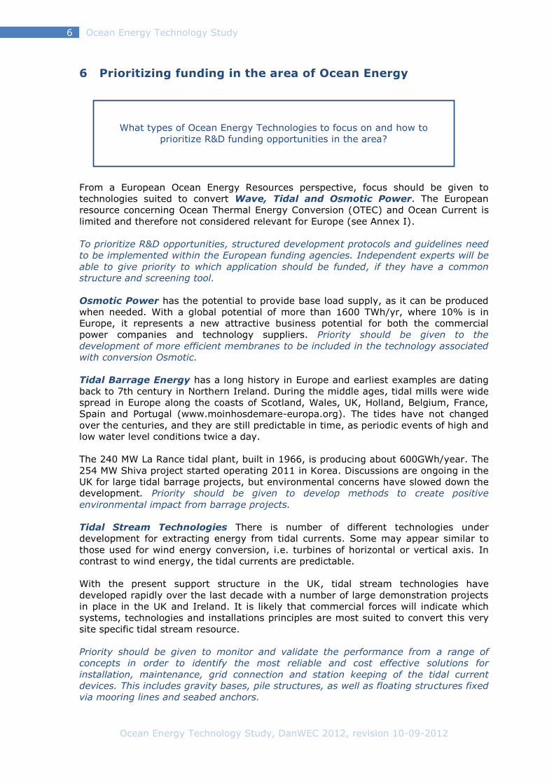
What types of Ocean Energy Technologies to focus on and how to
prioritize R&D funding opportunities in the area?
6 Prioritizing funding in the area of Ocean Energy
From a European Ocean Energy Resources perspective, focus should be given to
technologies suited to convert Wave, Tidal and Osmotic Power. The European
resource concerning Ocean Thermal Energy Conversion (OTEC) and Ocean Current is
limited and therefore not considered relevant for Europe (see Annex I).
To prioritize R&D opportunities, structured development protocols and guidelines need
to be implemented within the European funding agencies. Independent experts will be
able to give priority to which application should be funded, if they have a common
structure and screening tool.
Osmotic Power has the potential to provide base load supply, as it can be produced
when needed. With a global potential of more than 1600 TWh/yr, where 10% is in
Europe, it represents a new attractive business potential for both the commercial
power companies and technology suppliers. Priority should be given to the
development of more efficient membranes to be included in the technology associated
with conversion Osmotic.
Tidal Barrage Energy has a long history in Europe and earliest examples are dating
back to 7th century in Northern Ireland. During the middle ages, tidal mills were wide
spread in Europe along the coasts of Scotland, Wales, UK, Holland, Belgium, France,
Spain and Portugal (www.moinhosdemare-europa.org). The tides have not changed
over the centuries, and they are still predictable in time, as periodic events of high and
low water level conditions twice a day.
The 240 MW La Rance tidal plant, built in 1966, is producing about 600GWh/year. The
254 MW Shiva project started operating 2011 in Korea. Discussions are ongoing in the
UK for large tidal barrage projects, but environmental concerns have slowed down the
development. Priority should be given to develop methods to create positive
environmental impact from barrage projects.
Tidal Stream Technologies There is number of different technologies under
development for extracting energy from tidal currents. Some may appear similar to
those used for wind energy conversion, i.e. turbines of horizontal or vertical axis. In
contrast to wind energy, the tidal currents are predictable.
With the present support structure in the UK, tidal stream technologies have
developed rapidly over the last decade with a number of large demonstration projects
in place in the UK and Ireland. It is likely that commercial forces will indicate which
systems, technologies and installations principles are most suited to convert this very
site specific tidal stream resource.
Priority should be given to monitor and validate the performance from a range of
concepts in order to identify the most reliable and cost effective solutions for
installation, maintenance, grid connection and station keeping of the tidal current
devices. This includes gravity bases, pile structures, as well as floating structures fixed
via mooring lines and seabed anchors.

Ocean Energy Technology Study, DanWEC 2012, revision 10-09-2012
Ocean Energy Technology Study 7
Wave Energy has a global resource potential of 29.500 TWh/yr, where 10% is in
Europe, and several European countries are facing coastlines with wave energy of
different intensity per km coastline. There are differences from one country to the next
e.g. in terms of how far off the coast the water reach 50 meter depth, the seabed can
be of rock, sand, gravel or chalk. Some locations have large tidal height variation or
currents whereas other locations do not. Some locations are covered by ice part of the
year. These differences are to some extend reflected in the large number of
technologies proposed for converting the power of the waves.
The Pelamis wave energy converter is today the most advanced off-shore system
developed to a pre-commercial demonstration phase. Continuous development and
support is required over the next 20-30 years, in order to develop more economic
second and third generation wave energy conversion systems, as indicated in the
roadmap from ETI [2](see Annex II).
Wave energy converters deployed at sea today can be seen as front runners i.e.
technologies that with dedicated development teams, governmental support and
industrial involvement and backup have been able to secure sufficient funding to
develop and demonstrate that wave power can work and produce power.
In 2011, the first standards on how to measure and present the measured electrical
output were developed under IEC-TC 114. Based on these standards, the power
matrices measured at sea can be compared to results obtained in laboratory scales
and simulated using numerical models, which will feed back into further R&D efforts.
Figure 2 Pelamis wave energy converter off the coast of the Orkney Islands [w2]
Priority should be given to demonstrate a selection of different operating principles, in
order to identify the most efficient and reliable components, power take off systems,
mooring systems, electrical interconnections and grid connections. In parallel, priority
should be given to integrate the learning from these field tests into basic research,
focused on new or improved principles, materials, components and systems leading to
more economic second and third generation devices.

Ocean Energy Technology Study, DanWEC 2012, revision 10-09-2012
Ocean Energy Technology Study 8
6.1 Research & Development Due to the increasing number of wave energy converter (WEC) concepts, more than
100 are listed in the report by Thorpe [3]. Several initiatives have been taken to
introduce the structured development programs described for wave energy [4] and for
tidal energy [5] and comparable procedures for development, as described in
proceedings of the European project Equimar [w3].
In Denmark, several different WECs are being tested at sea and some are ready to be
deployed in larger scale at more exposed locations at sea. In response to this
situation, the Danish funding agency EUDP has funded an "industrial partnership
project" with the objective: To find ways for developers to form partnerships
concerning further research and development and increasing the value of invested
funding by sharing the results.
The partnership project has been carried out during the period 2011 – 2012 and
included interviews with the technology developers and joint workshops. The results
show that priory areas for joint development of wave energy conversion (in Denmark)
are very similar to the priority areas identified under the ETI / UKERC Roadmap study
[6] integrated in the European Energy Research Alliance’s (EERA) Ocean Energy Joint
Programme (section 10.6).
The priorities concerning wave energy development can be identified as:
Guidelines and standards
Performance guidelines and technical specifications
(IEC-PT 62600 is currently addressing these issues)
Device and system demonstrators
In Denmark, the time is ready to build and install at least 3 near-full scale prototypes
of the competing WECs before 2016. It is suggested that these systems are tested at
sea at a common test site (Danish Wave Energy Center) where cabling and monitoring
costs can be shared.
The ETI UK study suggests (see annex II):
1st generation device and array sea trials
Performance data collection
Installation recovery methods
Low-cost O&M techniques
Subcomponents
Cooperation and synergies between different technology developers and external
specialized companies on development of vital common components and utilization of
existing technologies to areas such as:
Moorings (Foundations and mooring systems)
Power Take-off (PTO) (Energy conversion system)
Power cables to the floating power plants (umbilical / wet HV connectors)
New concepts and research
This includes new devices and component development with a potential to reduce the
cost of electricity. Tracking the Cost of Energy (COE) will be mandatory (in Denmark),
combining a standardized design method with a verified energy performance
assessment (e.g. numerical and experimental).
Development of tools
Tools for resource analysis, design and optimization, device modeling, reliability
modeling, array design, interaction modeling and analysis.

Ocean Energy Technology Study, DanWEC 2012, revision 10-09-2012
Ocean Energy Technology Study 9
6.2 Market stimulation Public funding authorities will typically require matching private investment even at
this relative early stage of development. It is therefore proposed that a project specific
feed-in tariff based on the performance of the device (forsk-VE component in
Denmark) is applied for future prototype testing.
Such a performance based "feed-in" tarif will enable investors to have their
investment returned, if the prototype project operates according to a pre-specified
performance and maintenance scheme. Even if such project specific feed in tariffs are
very high compared to other sources of energy, it will help support and develop the
best systems, with a minimal risk for the public investment.
Such a scheme should give the investors return of investments if the WECs, which
over a defined period of 2 to 5 years, have demonstrated performance, survivability,
maintainability and reliability. Here after confidence will be sufficient to deploy a
larger numbers of devices at pre-specified locations, incorporating whatever new
knowledge established in the mean time.
6.3 Planning issues in different countries In Denmark exists a tradition for one-stop-shop concerning permits for power
production and deployment of WECs. This procedure is envied by colleagues e.g. in
the USA, where projects can be years delayed because of "blue tape" in the official
administration. Several Danish WEC developers hold such temporary permits at
development step 3 & 4 as described in section 6.
It is recommended that within Europe, the possible locations of larger wave and tidal
power plants should be identified,with due respect to how the power from such sites
can be grid connected. Such information is necessary to define the wave resource,
design conditions, deployment and grid connection costs, required to carry out the
Cost of Energy (COE) calculations.
6.4 Optimisation and learning The development is not a straight forward process i.e. lessons learned should be
incorporated and perhaps new discoveries also. For each individual project the
development spiral can illustrate this.
Figure 3 Symbol for the development spiral
Technological development within wave energy is therefore recommended to continue
at all levels from basic research to demonstration of prototypes and arrays. From a
Danish view point wave energy systems are not ready today to be tested in Arrays
until at least a few years of performance demonstration from a single prototype has
been accomplished, as indicated in table 2.

Ocean Energy Technology Study, DanWEC 2012, revision 10-09-2012
Ocean Energy Technology Study 10
The table below shows how the different stages of WEC development could be
foreseen to development based on the strategy proposed in this report.
The stages of WEC development are described in the reports from the OWEC-1 [7],
the Danish wave energy program [8], Equimar [W3], and IEA-OES [4] and on page 22
of this report.
Table 2 Proposed development schedule for Wave Energy in Europe
This section is partly based on the methodology and outcome of the UKERC and ETI
study, the Equimar project and the IEA-OES Annex II methodologies and the Danish
partnership project carried out between Danish wave energy developers and
associated companies, in which DanWEC has participated as an observer.
The Danish Industrial Partnership Project led by Aalborg University was initiated in
March 2011 and a first draft strategy report presented and discussed at a partnership
meeting March 22, 2012 in Hanstholm, Denmark.
7 Reviews of studies of the most promising technologies
There are a number of studies concerning selection of the most promising technologies
within wave energy and some of the most recent includes numerical models, in order
to calculate the wave energy converters performance.
The conclusion from these studies is that so far there is no consistent way to predict
which system for converting wave energy that eventually will take the lead. Even with
a broad selection of different sizes, operating principles and locations, the results are
not significantly different according to [9]:
The annual absorbed energy per characteristic mass was found to be in the
order of 1 MWh/tonne, whatever the device.
In order to identify the most promising technology, a more fruitful procedure can be to
take the development forward in steps, as mentioned above, combined with check
procedures for instance as described by the utility ESBI [w4].
This readiness levels described includes a check-list at each step of development –
such a check list could be helpful also in relation to public funding agencies concerning
when the development is ready to move from one step to the next at the fundamental
levels until the developers are ready to enter into a negotiation with utilities.
The incorporation of calculation of Cost of Energy – even in a simplified and
standardized form – can help identify and prioritize the areas that should be developed
further i.e. a standardised Cost of Energy calculation tool in excel has been developed
by Energinet.DK and can be downloaded [w5].
Ocean Energy Technology Study, DanWEC 2012, revision 10-09-2012
Ocean Energy Technology Study 11
7.1 Recommendation Development in steps combined with check points such as recommended by ESBI and
certification guideless by DNV, numerical and experimental verification, cost
calculations such as recommended by IEA_OES and Energinet.dk.
The Carbon Trust’s studies Future Marine Energy 2006 identified that the following
areas of innovation, as having most potential for cost of energy (CoE) reductions:
• Device components – Research into lowering costs and improving performance
of specific components in existing marine energy devices.
• Installation, operation and maintenance – Developing strategies to enable
marine energy devices to be installed, operated and maintained at a lower cost.
• Next generation concepts – Developing new device concepts that could
significantly lower the costs of marine energy compared to current front
runners.
The Marine Energy Accelerator (MEA) [12] focused on these areas and concluded:
Adding innovation to the learning by doing curve significantly accelerates cost reduction relative to the baseline case .
Survivability
The MEA’s study on costs of wave energy has shown that to compete with other
renewable energy technologies, wave energy developers will in the medium term need
to exploit high energy sites. These sites generally also have larger extreme waves, so
developers must make sure that their devices are designed with survivability built in.
Operations and maintenance
MEA’s analysis has also shown that operations and maintenance (O&M) costs make up
around a quarter of wave levelised cost of energy. This means that the development
of efficient O&M strategies must be a priority. Examples in the following chapter show
clearly that innovative O&M strategies or technologies can significantly reduce lifetime
costs at the device level, primarily by increasing the range of sea conditions in which
O&M can be undertaken, and by reducing the time required for operations. At the
array level, there are also opportunities for reducing O&M costs by developing efficient
deployment and recovery strategies for multiple devices, and by exploiting economies
of scale for planned maintenance. The simplest way to achieve low O&M costs is to
build extremely reliable devices that need very little maintenance.
Connection cost, and depth
The high baseline cost of wave energy also suggests that wave energy developers will
need to go relatively far offshore to energetic waters to generate competitively priced
electricity. This will require particular focus on reducing the cost of cabling and
connection to the national grid, perhaps by simplifying procedures or by using lighter
weight moorings or foundations and ensuring that devices can be installed in deep
water. If transit times to port are high, or if developers need to go far offshore to
access good resources, the focus on reducing planned and unplanned maintenance
interventions will be even more important.

Ocean Energy Technology Study, DanWEC 2012, revision 10-09-2012
Ocean Energy Technology Study 12
8 The status and potential of the ocean energy sector
Figure 4 Installed capacities of Ocean Energy Systems 2011 [OES][w6]
There are an increasing number of devices under development worldwide and the
installed capacity of wave & tidal systems at sea is shown on figure 4 above. Within
Europe, the countries with installed wave and tidal energy systems are summarized in
the table below with indications of the targets in respective countries.
Table 3 Status and targets of Wave and Tidal energy in Europe [OES][w6]
Wave Power Tidal
2011 Status kW
Target 2020 MW
Status MW
Target MW
UK 2000 4,80 2.0001
Ireland 500
France 200 2402 800
Portugal 400 300
Spain 300 100
Sweden 150
Denmark 250
1 Target for combine wave and Tidal 2 La Rance tidal barrage
Ocean Energy Technology Study, DanWEC 2012, revision 10-09-2012
Ocean Energy Technology Study 13
8.1 Status in selected countries 8.1.1 The UK
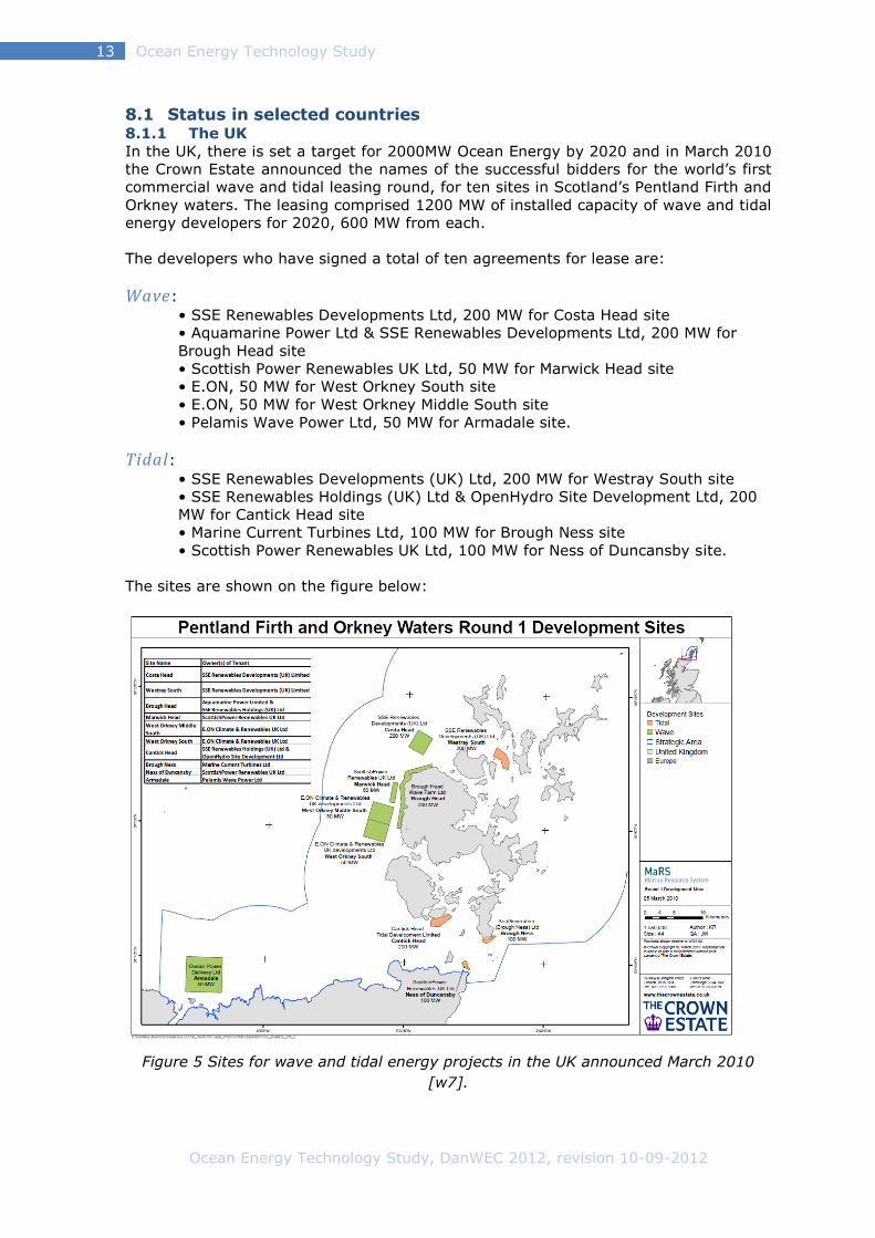
In the UK, there is set a target for 2000MW Ocean Energy by 2020 and in March 2010
the Crown Estate announced the names of the successful bidders for the world’s first
commercial wave and tidal leasing round, for ten sites in Scotland’s Pentland Firth and
Orkney waters. The leasing comprised 1200 MW of installed capacity of wave and tidal
energy developers for 2020, 600 MW from each.
The developers who have signed a total of ten agreements for lease are:
Wave:
• SSE Renewables Developments Ltd, 200 MW for Costa Head site
• Aquamarine Power Ltd & SSE Renewables Developments Ltd, 200 MW for
Brough Head site
• Scottish Power Renewables UK Ltd, 50 MW for Marwick Head site
• E.ON, 50 MW for West Orkney South site
• E.ON, 50 MW for West Orkney Middle South site
• Pelamis Wave Power Ltd, 50 MW for Armadale site.
Tidal: • SSE Renewables Developments (UK) Ltd, 200 MW for Westray South site
• SSE Renewables Holdings (UK) Ltd & OpenHydro Site Development Ltd, 200
MW for Cantick Head site
• Marine Current Turbines Ltd, 100 MW for Brough Ness site
• Scottish Power Renewables UK Ltd, 100 MW for Ness of Duncansby site.
The sites are shown on the figure below:
Figure 5 Sites for wave and tidal energy projects in the UK announced March 2010
[w7].

Ocean Energy Technology Study, DanWEC 2012, revision 10-09-2012
Ocean Energy Technology Study 14
Some of the technologies being developed in the UK are shown below.
Figure 6 The Aquamarine Oyster Device [w8] is presently being tested at the test site
EMEC in Orkney[w9]
Figure 7 The snake-like WEC Pelamis [w2]
Figure 8 Marine Current Turbines (MCT) SeaGen 1.2 MW installed in 2009 [w10]
Test site activity at the European Marine Energy Centre EMEC:
Pelamis P2 750kW Machine (Commissioned by Eon)
Pelamis P2 750kW Machine (Commissioned by Scottish Power Ren.)
Aquamarine Power Limited – Oyster 800 Stage 1
Wello Oy Penguin 500 kW wave converter
Open Hydro 250kW Open Centred tidal turbine deployed
Open Hydro – 600kW turbine deployed (not grid connected)
Tidal Generation Ltd 500kW tidal turbine deployed
Atlantis Resources Corporation AR1000 1 MW tidal turbine deployed
Scotrenewables SR250 floating tidal turbine deployed
Hammerfest Strom 1MW tidal turbine deployed
Voith Hydro tidal turbine
Ocean Energy Technology Study, DanWEC 2012, revision 10-09-2012
Ocean Energy Technology Study 15
8.1.2 Ireland
The Government in Ireland has set a target of 500 MW Ocean Energy by 2020. The
government has allocated €27m to be administrated by the Ocean Energy Deployment
Unit [w11].
The utility ESBI [w12] has actively been involved in Ocean Energy technology and
resource studies as well as helping develop guidelines for Electrical connections. ESBI
also has a target of owning 150 MW of generation from the emerging area of wave
and tidal energy in its portfolio by 2020. WestWave represents the third and final step
in the Irish Government’s Ocean Energy Strategy before commercial projects can
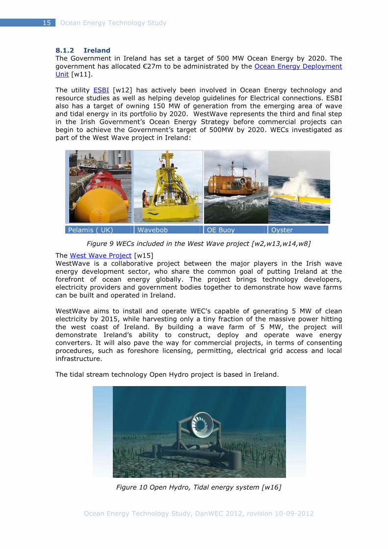
begin to achieve the Government’s target of 500MW by 2020. WECs investigated as
part of the West Wave project in Ireland:
Pelamis ( UK) Wavebob OE Buoy Oyster
Figure 9 WECs included in the West Wave project [w2,w13,w14,w8]
The West Wave Project [w15]
WestWave is a collaborative project between the major players in the Irish wave
energy development sector, who share the common goal of putting Ireland at the
forefront of ocean energy globally. The project brings technology developers,
electricity providers and government bodies together to demonstrate how wave farms
can be built and operated in Ireland.
WestWave aims to install and operate WEC's capable of generating 5 MW of clean
electricity by 2015, while harvesting only a tiny fraction of the massive power hitting
the west coast of Ireland. By building a wave farm of 5 MW, the project will
demonstrate Ireland’s ability to construct, deploy and operate wave energy
converters. It will also pave the way for commercial projects, in terms of consenting
procedures, such as foreshore licensing, permitting, electrical grid access and local
infrastructure.
The tidal stream technology Open Hydro project is based in Ireland.
Figure 10 Open Hydro, Tidal energy system [w16]
Ocean Energy Technology Study, DanWEC 2012, revision 10-09-2012
Ocean Energy Technology Study 16
8.1.3 France
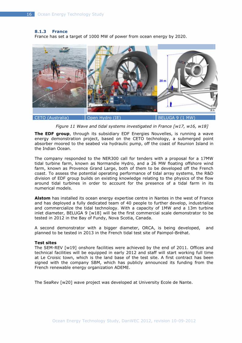
France has set a target of 1000 MW of power from ocean energy by 2020.
CETO (Australia) Open Hydro (IE) BELUGA 9 (1 MW)
Figure 11 Wave and tidal systems investigated in France [w17, w16, w18]
The EDF group, through its subsidiary EDF Energies Nouvelles, is running a wave
energy demonstration project, based on the CETO technology, a submerged point
absorber moored to the seabed via hydraulic pump, off the coast of Reunion Island in
the Indian Ocean.
The company responded to the NER300 call for tenders with a proposal for a 17MW
tidal turbine farm, known as Normandie Hydro, and a 26 MW floating offshore wind
farm, known as Provence Grand Large, both of them to be developed off the French
coast. To assess the potential operating performance of tidal array systems, the R&D
division of EDF group builds on existing knowledge relating to the physics of the flow
around tidal turbines in order to account for the presence of a tidal farm in its
numerical models.
Alstom has installed its ocean energy expertise centre in Nantes in the west of France
and has deployed a fully dedicated team of 40 people to further develop, industrialize
and commercialize the tidal technology. With a capacity of 1MW and a 13m turbine
inlet diameter, BELUGA 9 [w18] will be the first commercial scale demonstrator to be
tested in 2012 in the Bay of Fundy, Nova Scotia, Canada.
A second demonstrator with a bigger diameter, ORCA, is being developed, and
planned to be tested in 2013 in the French tidal test site of Paimpol-Bréhat.
Test sites
The SEM-REV [w19] onshore facilities were achieved by the end of 2011. Offices and
technical facilities will be equipped in early 2012 and staff will start working full time
at Le Croisic town, which is the land base of the test site. A first contract has been
signed with the company SBM, which has publicly announced its funding from the
French renewable energy organization ADEME.
The SeaRev [w20] wave project was developed at University Ecole de Nante.
Ocean Energy Technology Study, DanWEC 2012, revision 10-09-2012
Ocean Energy Technology Study 17
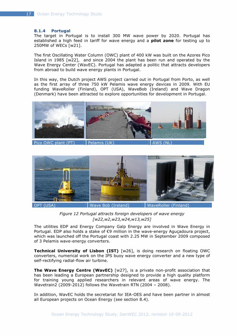
8.1.4 Portugal
The target in Portugal is to install 300 MW wave power by 2020. Portugal has
established a high feed in tariff for wave energy and a pilot zone for testing up to
250MW of WECs [w21].
The first Oscillating Water Column (OWC) plant of 400 kW was built on the Azores Pico
Island in 1985 [w22], and since 2004 the plant has been run and operated by the
Wave Energy Center (WavEC). Portugal has adapted a politic that attracts developers
from abroad to build wave energy plants in Portugal.
In this way, the Dutch project AWS project carried out in Portugal from Porto, as well
as the first array of three 750 kW Pelamis wave energy devices in 2009. With EU
funding WaveRoller (Finland), OPT (USA), WaveBob (Ireland) and Wave Dragon
(Denmark) have been attracted to explore opportunities for development in Portugal.
Pico OWC plant (PT) Pelamis (UK) AWS (NL)
OPT (USA) Wave Bob (Ireland) WaveRoller (Finland)
Figure 12 Portugal attracts foreign developers of wave energy
[w22,w2,w23,w24,w13,w25]
The utilities EDP and Energy Company Galp Energy are involved in Wave Energy in
Portugal. EDP also holds a stake of €9 million in the wave-energy Aguçadoura project,
which was launched off the Portugal coast with 2.25 MW in September 2009 composed
of 3 Pelamis wave-energy converters.
Technical University of Lisbon (IST) [w26], is doing research on floating OWC
converters, numerical work on the IPS buoy wave energy converter and a new type of
self-rectifying radial-flow air turbine.
The Wave Energy Centre (WavEC) [w27], is a private non-profit association that
has been leading a European partnership designed to provide a high quality platform
for training young applied researchers in relevant areas of wave energy. The
Wavetrain2 (2009-2012) follows the Wavetrain RTN (2004 – 2008).
In addition, WavEC holds the secretariat for IEA-OES and have been partner in almost
all European projects on Ocean Energy (see section 8.4).

Ocean Energy Technology Study, DanWEC 2012, revision 10-09-2012
Ocean Energy Technology Study 18
8.1.5 Spain
Spain has a target of about 100 MW by 2020 to be deployed at sites in the Northern
part of Spain. Compared to other European countries such as UK, DK, NO, PT and SW,
Spain is a relative new player on developing wave energy, but since 2005 Spain has
showed a fast growing interest in this field.
In November 2011, the 300 kW Mutriku OWC wave power plant was handed over to
EVE (the Basque energy agency) [w28]. equipped with 16 air turbines from Voith
Hydro Wavegen and guarantees for performance and availability. The plant is housed
within a breakwater at the port of Mutriku. During commissioning and acceptance
testing, the plant has produced 100MWh to the grid.
OPT (Iberdrola) [w24] Mutriku OWC breakwater (Voith Hydro Wavegen Ltd)
Figure 13 Spanish projects includes the 300 kW OWC Mutriku breakwater
OPT is interested in the Spanish market, and also three technologies shown below
were investigated in the period 2008-10 co-ordinated by Tecnalia. The APC-Pisys is
now defining a project aimed to design, build and deploy a 1:5 scale wave energy
converter prototype during 2012.
Hidroflot (Spain) APC-Pisys (1:5 scale) OCEANTEC
Figure 14 Three technologies developed in one project co-ordinated by Technalia
[w29,w30,w31]
Test Sites
The Biscay Marine Energy Platform (bimep)[32], occupies a 5.3 km2 marked area
excluded for navigation and maritime traffic, and located at a minimum distance of
1,700 m from shore, close enough for fast access to deployed devices. The total power
of 20 MW is distributed over four offshore connection points of 5 MW each at 50-90 m
water depths. bimep is expected to commence operations in the last quarter of 2012.
Ocean Energy Technology Study, DanWEC 2012, revision 10-09-2012
Ocean Energy Technology Study 19
8.1.6 Sweden
A marine spatial planning process of the Swedish territorial coastal waters is planned
to commence in 2012. Areas with potential for energy conversion by wave power
plants, if applicable, will be identified during this process.
Sweden was a pioneer within wave power in the early 1970s and hosted the first
international symposium on wave energy in 1979 in Gothenburg. Since Mats Lejon and
his students at Uppsala University in 2002 started working on the “Point Absorber”,
driving a direct electricity producing linear generator placed on the seabed, Sweden
has taken a renewed interest in wave power. In many ways, this Seabased system
compares to the Danish Wave Power system developed and tested in the 1980s.
The company Seabased [33] was formed in 2002 to develop the research at Uppsala
University related to linear generator wave power. During the period 2006 – 2011, the
Lysekil project was carried out focusing on ocean tests, generator and buoy design,
and model development, including a 10-unit field research site including a submarine
switchgear and sea cable connection to load.
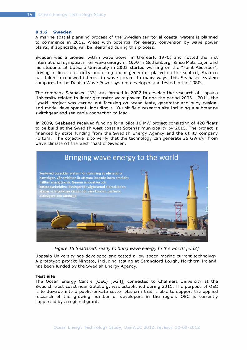
In 2009, Seabased received funding for a pilot 10 MW project consisting of 420 floats
to be build at the Swedish west coast at Sotenäs municipality by 2015. The project is
financed by state funding from the Swedish Energy Agency and the utility company
Fortum. The objective is to verify that the technology can generate 25 GWh/yr from
wave climate off the west coast of Sweden.
Figure 15 Seabased, ready to bring wave energy to the world! [w33]
Uppsala University has developed and tested a low speed marine current technology.
A prototype project Minesto, including testing at Strangford Lough, Northern Ireland,
has been funded by the Swedish Energy Agency.
Test site
The Ocean Energy Centre (OEC) [w34], connected to Chalmers University at the
Swedish west coast near Göteborg, was established during 2011. The purpose of OEC
is to develop into a public-private sector platform that is able to support the applied
research of the growing number of developers in the region. OEC is currently
supported by a regional grant.

Ocean Energy Technology Study, DanWEC 2012, revision 10-09-2012
Ocean Energy Technology Study 20
8.1.7 Denmark
Denmark today has some of the best documented wave power concepts in the world.
This has been achieved with relatively modest funds, as the development of projects
typically has been carried out gradually scaling up and documenting the technologies.
This has minimized the economic and security risks. A highly professional level has
been achieved through cooperation between research institutions, project developers
and industry.
The Danish Wave Energy Program is often referred to as a unique program in the
world and what was unique is that the program had a bottom up approach,
implementing a development protocol, funding the projects at early stage with 100%
and by doing so retaining the right to publish the performance and results in the public
domain.
The Danish Wave Energy Program, with a budget of 6 M€ over the period 1998 – 2001
[8], focused on the first three steps of this development in which more than 40
different ideas were tested at initial phase (step1), about 15 projects more elaborate
tested at step 2 and only the Wave Dragon Project reached step 3 within the
program period, building a prototype of 20 kW for research and test at the benign test
site in Nissum Bredning.
The development protocol described a procedure in which the WECs roughly could be
developed in five steps, where the WEC is gradually built and tested in larger and
larger scale – while design, components, power take-off and numerical and economical
calculations are conducted with increasing accuracy. This development procedure is
not only technical, but evenly suitable for teambuilding, development of business
models and optimization of the technology underway.
Figure 16 The typical steps of wave energy development in DK.
Each step has its own challenges and from successful completion of one step to the
next, the projects technological readiness level (TRL) increases, with a minimal risk in
terms of investment. If major design changes are considered or enforced, the device
development can shift back to the relevant step.
Step 1
Basic research and model testing
Step 2
Design optimization feasibility studies additional model tests in larger scale
Step 3
Development and testing of components and prototype testing in the protected waters
Step 4
Close to full scale grid-connected experiments for example at DanWEC in Hanstholm
Step 5
Demonstration of wave energy parks consisting of multiple devices

Ocean Energy Technology Study, DanWEC 2012, revision 10-09-2012
Ocean Energy Technology Study 21
The five steps are described below with examples of Danish projects at each step.
Step 1: Concerns initial testing of new ideas and concepts, typically it includes
building of a model representing the idea for initial testing in a wave flume or tank in
co-operation with a university, typically Aalborg University (AAU) in Denmark. AAU
has in this way carried out numerous experiments with different concepts, and
documented the results in a standardized report format. Some experiments have
formed the basis for PhD projects and development of new ideas. The tank testing
protocol further formed the basis for the first Annex II of the IEA-OES implementing
agreement in [13, w35].
Step 2: This concerns further development and laboratory testing of selected
concepts, with a view to obtaining quantitative results for survivability and energy
efficiency, etc., studies are carried out in wave tanks and typically combined with
numerical modeling. Of the 15 phase 2 projects, which was tested during the wave
energy program, described in the report [8], four of the initiated projects has since
then been developed further in the Denmark. The SWAN dk3 project was based on the
Japanese BBDB concept is now taken further in Japan and in Ireland – known as the
OE Buoy [w14].
Step 3: Prototype development and testing in the Danish practice has proven to
include long-term testing of small scale pilot projects in protected sea areas, while
business models and partnerships are developed and established. Wave Dragon
[w36] was built in scale 1:4,5 and launched in 2002 and tested in the Danish
sheltered site Nissum Bredning, until the ice winter 2009. Waveplane [w37] has
tested a smaller prototype in Ringkøbing fjord for private funds. The project “Tusind
ben” was continued as the Wavestar [w38] and during the period 2006 – 2010 it was
tested at Nissum Bredning test site in scale 1:10, where it has produced data and
power. The project “Poseidons organ” has been developed further as a Floating
Power Plant [w39], built and tested at the offshore windmill park Vindeby in the
period 2007-2011. Dexawave [w40] installed a small prototype in 2009 followed by a
larger version installed at Hanstholm in 2011.
Step 4 Demonstration in larger scale. This step includes the installation of a larger
electricity producing prototype in order to verify in detail its performance in realistic
sea conditions. Wavestar build and installed a section of a 1.2 scale machine in
Hanstholm in 2009. Connected to the electricity grid this machine has produced
electricity to the grid over a two-year period. A special performance based tariff is
agreed with Energinet.dk which is paid for the electricity or absorbed power produced
in accordance with predictions.
Step 5 Commercialization. To the extent that a project has documented its energy
production and economics and contracted or sold one or more prototypes e.g. to an
energy company, the project has reached step 5. Presently, there are no Danish
projects that have reached this level.
Test Site
With the testing of Wavestar and Dexawave at Hanstholm the test site DanWEC
[w41], situated at the west coast of Denmark, is in the process of building up its
infrastructure to become a green lab and the site for future testing of WECs in
Denmark at a scale somewhat smaller than required e.g. at EMEC, as described in the
OES Annex II report [14].
Ocean Energy Technology Study, DanWEC 2012, revision 10-09-2012
Ocean Energy Technology Study 22
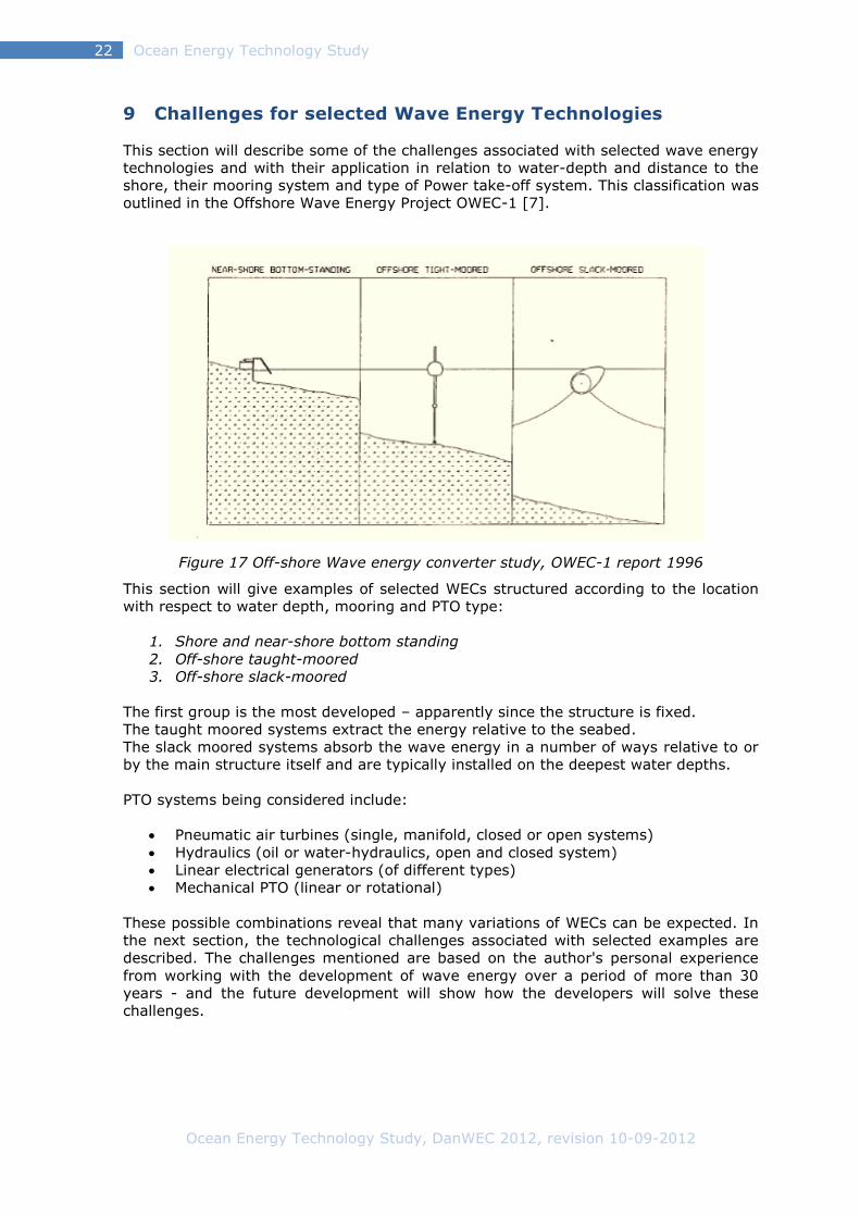
9 Challenges for selected Wave Energy Technologies
This section will describe some of the challenges associated with selected wave energy
technologies and with their application in relation to water-depth and distance to the
shore, their mooring system and type of Power take-off system. This classification was
outlined in the Offshore Wave Energy Project OWEC-1 [7].
Figure 17 Off-shore Wave energy converter study, OWEC-1 report 1996
This section will give examples of selected WECs structured according to the location
with respect to water depth, mooring and PTO type:
1. Shore and near-shore bottom standing
2. Off-shore taught-moored
3. Off-shore slack-moored
The first group is the most developed – apparently since the structure is fixed.
The taught moored systems extract the energy relative to the seabed.
The slack moored systems absorb the wave energy in a number of ways relative to or
by the main structure itself and are typically installed on the deepest water depths.
PTO systems being considered include:
Pneumatic air turbines (single, manifold, closed or open systems)
Hydraulics (oil or water-hydraulics, open and closed system)
Linear electrical generators (of different types)
Mechanical PTO (linear or rotational)
These possible combinations reveal that many variations of WECs can be expected. In
the next section, the technological challenges associated with selected examples are
described. The challenges mentioned are based on the author's personal experience
from working with the development of wave energy over a period of more than 30
years - and the future development will show how the developers will solve these
challenges.
Ocean Energy Technology Study, DanWEC 2012, revision 10-09-2012
Ocean Energy Technology Study 23
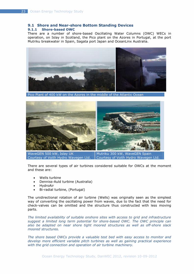
9.1 Shore and Near-shore Bottom Standing Devices 9.1.1 Shore-based OWC
There are a number of shore-based Oscillating Water Columns (OWC) WECs in
operation, on Islay in Scotland, the Pico plant on the Azores in Portugal, at the port
Mutriku breakwater in Spain, Sagata port Japan and OceanLinx Australia.
Pico Plant of 400 kW on the Azores in the middle of the Atlantic Ocean
WaveGEN 500 kW, Islay UK
Courtesy of Voith Hydro Wavegen Ltd.
Mutriku 300 kW, WaveGEN Spain
Courtesy of Voith Hydro Wavegen Ltd.
There are several types of air turbines considered suitable for OWCs at the moment
and these are:
Wells turbine
Denniss-Auld turbine (Australia)
HydroAir
Bi-radial turbine, (Portugal)
The unidirectional rotation of air turbine (Wells) was originally seen as the simplest
way of converting the oscillating power from waves, due to the fact that the need for
check-valves can be omitted and the structure thus constructed with less moving
parts.
The limited availability of suitable onshore sites with access to grid and infrastructure
suggest a limited long term potential for shore-based OWC. The OWC principle can
also be adapted on near shore tight moored structures as well as off-shore slack
moored structures.
The shore based OWCs provide a valuable test bed with easy access to monitor and
develop more efficient variable pitch turbines as well as gaining practical experience
with the grid connection and operation of air turbine machinery.

Ocean Energy Technology Study, DanWEC 2012, revision 10-09-2012
Ocean Energy Technology Study 24
9.1.2 Near-shore bottom standing converter
The Wavestar [w38] installed at Hanstholm in Denmark holds deployment and power
generation permit up to November 2013. The plant consists of two Ø5 m floats which
activated by the waves move up and down and a hydraulic PTO system which drives a
generator that produces electricity. In cases of extreme conditions, the floaters are
lifted out of the water and in even more extreme situations, the whole construction
can be jacked up and down on four steel tubes, which are attached to a concrete
foundation on the seabed.
The principles of Wavestar was tested in Nissum Bredning in scale 1:10 before being
tested in larger scale and in a rougher environment at Hanstholm. The present test
unit has a generator capacity of 80 kW and maximum measured an average power
output of around 40 kW. Daily and monthly summaries of production data are
presented online and these data forms the basis for a payment based on a project
specific performance "feed-in" tariff agreed with Energinet.dk.
During 2011, DanWEC [w41] introduced tours with the opportunity to visit Wavestar
that can be accessed via a 400-metre bridge leading to the structure from the shore.
This has proved to be a unique way to promote an understanding of wave power for
families, companies, schools, and prominent personalities such as climate and energy
ministers as well as the Crown Prince of Denmark.
Figure 18 Wavestar in operation.
Wavestar is involved in a number of development activities aiming at increasing
energy production and reducing costs. This includes the development of improved
control strategies for the PTO, materials research (section 9.2) and participating in EU
projects with partners from the UK, Poland and Spain.
Wavestar is developed based on a unique safety system, whereby it can lift the
floaters out of the water in storm situations. This feature has enabled Wavestar to
survive in the harsh environment over several years so far. The challenge lies in how
to develop more cost effective structures and a high efficient PTO system. Combined
wind and wave farms could provide synergies in relation to grid connections, use of
sea space, energy production and use of O&M personal. Wavestar has entered a co-
operation agreement with the utility DongEnergy to investigate this issue further.
Ocean Energy Technology Study, DanWEC 2012, revision 10-09-2012
Ocean Energy Technology Study 25
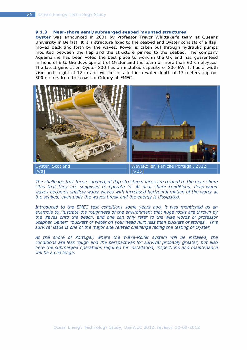
9.1.3 Near-shore semi/submerged seabed mounted structures
Oyster was announced in 2001 by Professor Trevor Whittaker's team at Queens
University in Belfast. It is a structure fixed to the seabed and Oyster consists of a flap,
moved back and forth by the waves. Power is taken out through hydraulic pumps
mounted between the flap and the structure pinned to the seabed. The company
Aquamarine has been voted the best place to work in the UK and has guaranteed
millions of £ to the development of Oyster and the team of more than 60 employees.
The latest generation Oyster 800 has an installed capacity of 800 kW. It has a width
26m and height of 12 m and will be installed in a water depth of 13 meters approx.
500 metres from the coast of Orkney at EMEC.
Oyster, Scotland
[w8]
WaveRoller, Peniche Portugal, 2012.
[w25]
The challenge that these submerged flap structures faces are related to the near-shore
sites that they are supposed to operate in. At near shore conditions, deep-water
waves becomes shallow water waves with increased horizontal motion of the water at
the seabed, eventually the waves break and the energy is dissipated.
Introduced to the EMEC test conditions some years ago, it was mentioned as an
example to illustrate the roughness of the environment that huge rocks are thrown by
the waves onto the beach, and one can only refer to the wise words of professor
Stephen Salter: "buckets of water on your head hurt less than buckets of stones". This
survival issue is one of the major site related challenge facing the testing of Oyster.
At the shore of Portugal, where the Wave-Roller system will be installed, the
conditions are less rough and the perspectives for survival probably greater, but also
here the submerged operations required for installation, inspections and maintenance
will be a challenge.

Ocean Energy Technology Study, DanWEC 2012, revision 10-09-2012
Ocean Energy Technology Study 26
9.2 Offshore tight-moored 9.2.1 Taught moored Point absorbers reacting against the seabed
In Sweden and Australia, points-absorbers which exploit the movement relative to the
seabed are explored — and where PTO is located on the seabed. The PTO of the
Swedish absorbers is based on a submerged linear electrical generator, while the
Australian uses a submerged hydraulic PTO. The Swedish float is placed in sea areas
where there are no tides, while the Australian buoy is operated just under the surface
of the ocean, in order not to be influenced by the tide. The DWP point absorber tested
in scale 1:4 off Hanstholm provided performance data over a period of 6 months
during 1995-96 [16]. A Norwegian point absorber, Bolt [w33], tested in Norway has
the PTO on the surface.
Seabased 30 kW, Sweden [w33] Ceto, 200 kW, Australia [w17]
Fred Olsen, Bolt 45 kW, Norway [w44] DWP Point absorber, 1:4 Denmark
The advantage of these tight moored point absorber systems are that the costs of
mooring are incorporated in the Power Take-off and the footprint of the mooring
therefore relatively small. The challenge is to avoid the moorings be affected by
snatch loads and end-stop loads which can be associated with the characteristics and
limited stroke length of the PTO.

Ocean Energy Technology Study, DanWEC 2012, revision 10-09-2012
Ocean Energy Technology Study 27
Resen Energy [w45] has received financial support for the test of a new tight moored
principle "Lever Operated Pivoting Float" (LOPF), which is a principle developed in the
United States that Resen has bought. The initial proof of concept has been carried out
in the wave tank at Aalborg University.
Figure 19 Lever Operated Pivoting Float, AAU 2012
Under the MaRINET programme Resen has applied to test a 2 kW unit in the deep
water tank of ECN in Nantes in France. The test is expected to take place in autumn
2012, if EU authorization is given. The challenge for this point absorber on the initial
step – is to find reliable ways to transmit the electricity to the seabed.

Ocean Energy Technology Study, DanWEC 2012, revision 10-09-2012
Ocean Energy Technology Study 28
9.3 Offshore slack moored devices 9.3.1 Heaving Buoys
Point absorbers
A number of slack moored point absorbers shown in the figure below looks at the
surface almost the same as the tight moored point absorbers (section 6.2.1.).
However, the OPT PowerBuoy and the WaveBob takes advantage of the relative
movement between a float and a submerged volume below sea level via a PTO.
OPT PowerBuoy, USA & UK (EMEC) [w24] Wave Bob, Ireland [w13]
Figure 20 Slack moored point absorbers
Design of a mooring system with a small footprint and the development of a power-
cable connection to the seabed, which can easily be detached when the system is due
for maintenance, are challenges associated with this type of devices.
The use of linear hydraulic rams require that the hydraulic circuit is specially designed
to deal with the typical unconventional high ram speeds required to obtain high point
absorber efficiency. The typical lifetime of hydraulic seals is about 20000 km – which
with an average travel of one meter per 8 seconds would be travelled in 5 years. The
rams need some type of protection to prevent ingress of seawater that could rapidly
lead to deterioration of the ram’s surface and loss of function.
It appears that PTO systems based on hydraulics today, are not much more efficient
compared to the PTO based on air turbines.
The slack-moored IPS Buoy developed and tested during
the 1970s in Sweden was promoted as suitable test unit
for off-shore devices as part of the OWEC-1 project [7].
During 2001-2007, the buoy was developed as AquaBuOY
by AquaEnergy/Finavera USA/Canada. A prototype was
built, installed and sank outside Oregon in 2007 –
Finavera consequently stopped further development on
the project and consequently focused on wind energy
development.
A revised version of the IPS buoy has been built and
tested by WAVES4POWER [w46] in 2010 in Sweden - 40
years after the first tests!
Ocean Energy Technology Study, DanWEC 2012, revision 10-09-2012
Ocean Energy Technology Study 29
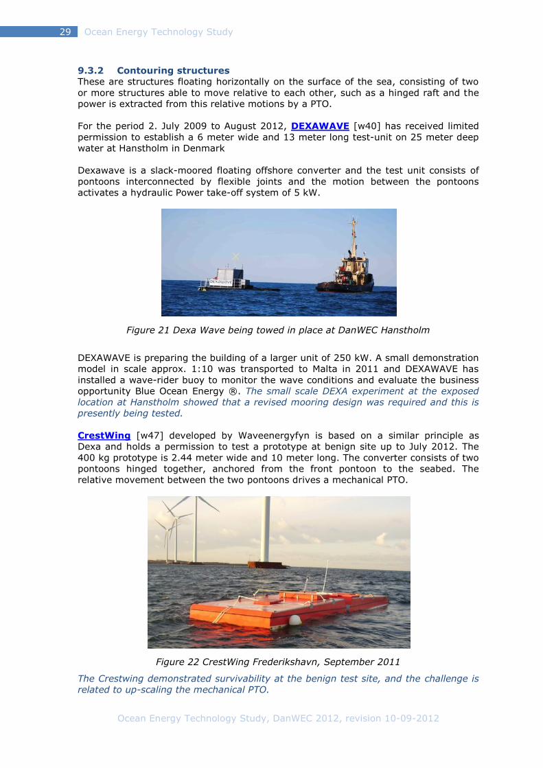
9.3.2 Contouring structures
These are structures floating horizontally on the surface of the sea, consisting of two
or more structures able to move relative to each other, such as a hinged raft and the
power is extracted from this relative motions by a PTO.
For the period 2. July 2009 to August 2012, DEXAWAVE [w40] has received limited
permission to establish a 6 meter wide and 13 meter long test-unit on 25 meter deep
water at Hanstholm in Denmark
Dexawave is a slack-moored floating offshore converter and the test unit consists of
pontoons interconnected by flexible joints and the motion between the pontoons
activates a hydraulic Power take-off system of 5 kW.
Figure 21 Dexa Wave being towed in place at DanWEC Hanstholm
DEXAWAVE is preparing the building of a larger unit of 250 kW. A small demonstration
model in scale approx. 1:10 was transported to Malta in 2011 and DEXAWAVE has
installed a wave-rider buoy to monitor the wave conditions and evaluate the business
opportunity Blue Ocean Energy ®. The small scale DEXA experiment at the exposed
location at Hanstholm showed that a revised mooring design was required and this is
presently being tested.
CrestWing [w47] developed by Waveenergyfyn is based on a similar principle as
Dexa and holds a permission to test a prototype at benign site up to July 2012. The
400 kg prototype is 2.44 meter wide and 10 meter long. The converter consists of two
pontoons hinged together, anchored from the front pontoon to the seabed. The
relative movement between the two pontoons drives a mechanical PTO.
Figure 22 CrestWing Frederikshavn, September 2011
The Crestwing demonstrated survivability at the benign test site, and the challenge is
related to up-scaling the mechanical PTO.

Ocean Energy Technology Study, DanWEC 2012, revision 10-09-2012
Ocean Energy Technology Study 30
Pelamis-Wave Power, Pelamis [w2] is this year (2012) celebrating its 14th birthday
and Richard Yemm, inventor and initiator of the project, writes on Pelamis home page:
“It’s unbelievable how much Pelamis has achieved over the past fourteen years.
When we started wave energy was an academic curiosity, and now we are an
important part of Scottish and UK Government strategy, have real machines
generating into the grid, and utility customers developing real wave farms off our
shores. From the first small tank test model in 1998 we have now designed, built and
tested six full-scale machines and through that amassed a vast pool of knowledge and
experience that gives us unrivalled insight into what we need to do next to deliver
commercial wave farms in the next few years. It has been a tough but rewarding 14
years since our inception, and there is more than a tingle of excitement if I allow
myself to think where we may be in another 14 years’ time!”
In March 2012, it was announced that Vattenfall signed up to take the last berth at
EMEC in order to test a Pelamis machine in Orkney from 2014. “We are working with
Vattenfall on a joint venture called Aegir Wave Power”, initially developing a 10MW
wave farm off the coast of Shetland. Vattenfall also confirmed their intention to order
a single Pelamis machine later this year, depending on the progress of the Aegir
project.
Pelamis inventor and founder Richard Yemm was awarded the prestigious Saltire Prize
Award Medal by the Scottish Government, which recognizes outstanding contributions
by individuals and groups to the development of marine power generation. (Pelamis
newsletter 2012-04-13)
Figure 23 Pelamis 2 During towing towards EMEC test site.
The challenge facing Pelamis, as the most obvious candidate for further full scale
demonstration, is not only to survive the forces of the sea, generating power,
reliability and maintainability – but also being able to deal with the pressure from all
sides who want to see fast results.

Ocean Energy Technology Study, DanWEC 2012, revision 10-09-2012
Ocean Energy Technology Study 31
9.3.3 Overtopping and inflow systems
Wave Dragon [w36] has been tested in Nissum Bredning since 2003 and the plant's
electricity generation license runs to 30. June 2012. The ice winter 2010 did, however,
give a reason to end the tests, as shown in the below photo.
Figure 24 Wave Dragon on ice
Wave Dragon uses the overtopping principle, where waves wash up in a reservoir
above sea-level and water is discharged through a series of low head water turbines
operating generators producing electricity. The plant tested had an installed power of
20 kW and a weight of 237 tons. The prototype plant was 58 meters wide, 33 meters
long with a draught of 3.6 meters.
Wave Dragon has submitted an Environmental Impact Assessment and application for
consent to install a pre-commercial demonstrator off the coast of Milford Haven,
Wales.
In 2011, Wave Dragon received support from the Danish funding agency EUDP to
prepare a certified design of a full-scale 1.5 MW demonstration unit to the wave
conditions at the test site DanWEC, Hanstholm. Furthermore, Wave Dragon
participated in EU projects such as Wave-Net, CA-OE, WavePlam, Equimar, Wavetrain
I and II (and have presently still onewave-trainees employed).
The challenge facing the Wave Dragon is the design of a reliable mooring system and
the power cable connecting from the device to the seabed.
WavePlane A/S [w37] had since October 2008 permit for their facilities at
Hanstholm. The machine is a floating V-shaped design, with the stern against the
incoming waves. The waves roles into funnels over an "artificial beach", and the water
is set in a rotating motion exhausted through turbines on each side generating
electricity. Establishment permit expired in august 2009, and the plant is currently not
in the test at sea.
The unique feature of the Waveplane is its
ability to stay calm in the waves, as they
pass over and into the structure. This
requires a careful design, which had been
proven in smaller scales. This feature
could significantly reduce the loadings on
the mooring system.
One of the challenges for WavePlane is to
cost effectively to convert the low head
flow of seawater into electricity.

Ocean Energy Technology Study, DanWEC 2012, revision 10-09-2012
Ocean Energy Technology Study 32
9.3.4 Floating OWC
Figure 25 OE Buoy, 20 kW, Ireland [w14]
In Ireland, Ocean Energy is developing the OE Buoy. The buoy has been tested in
scale 1:4 at the Irish test site in Donagal bay. The principle is a floating OWC invented
in Japan known under the name of BBDB. This BBDB principle on DHI was tested
during the Danish Wave Program of under the name Swan DK3 and ongoing
experiments are taking place at Saga University in Japan with variation of the concept.
The backward bended column of water extending under the hull activates the air
driving an air turbine. Ocean Energy Limited has in 2012 landed a deal to grid-connect
its first full-scale device at Wave Hub [w48].
The challenge facing the OE-Buoy is the development of a reliable and affordable
mooring system that will not influence the pitching motion of the device.
Leancon [w49] received permission to establish an experimental scale model at
Nissum Bredning at a location approximately 200 m from the beach and approximately
500 m from Nissum Bredning test site.
Figure 26 Leancon multi OWC system
The prototype is a scale 1:10 model of a floating multi OWC-installations. The model
has a weight of about 2 tons, manufactured in glass fiber. It is 24 meters wide and 11
meters long. Top of the structure is about 1 m above the waterline. The model will be
equipped with air turbine, generator and measuring equipment sufficient to evaluate
the performance and structural loads.
The challenge facing Leancon is how to complete such a large project single handed
within a reasonable time – the building and preparing of the large prototype is carried
out as a one-man project, down to the smallest details – it is indeed a challenge.
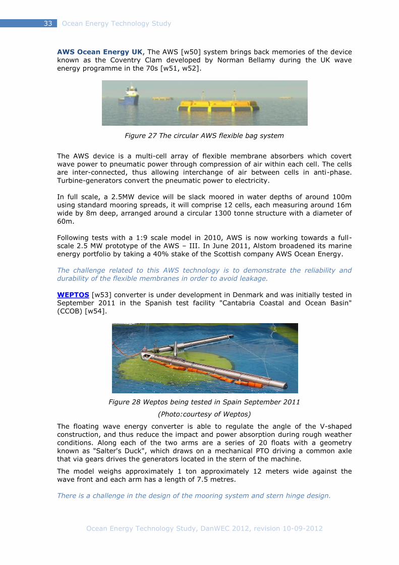
Ocean Energy Technology Study, DanWEC 2012, revision 10-09-2012
Ocean Energy Technology Study 33
AWS Ocean Energy UK, The AWS [w50] system brings back memories of the device
known as the Coventry Clam developed by Norman Bellamy during the UK wave
energy programme in the 70s [w51, w52].
Figure 27 The circular AWS flexible bag system
The AWS device is a multi-cell array of flexible membrane absorbers which covert
wave power to pneumatic power through compression of air within each cell. The cells
are inter-connected, thus allowing interchange of air between cells in anti-phase.
Turbine-generators convert the pneumatic power to electricity.
In full scale, a 2.5MW device will be slack moored in water depths of around 100m
using standard mooring spreads, it will comprise 12 cells, each measuring around 16m
wide by 8m deep, arranged around a circular 1300 tonne structure with a diameter of
60m.
Following tests with a 1:9 scale model in 2010, AWS is now working towards a full-
scale 2.5 MW prototype of the AWS – III. In June 2011, Alstom broadened its marine
energy portfolio by taking a 40% stake of the Scottish company AWS Ocean Energy.
The challenge related to this AWS technology is to demonstrate the reliability and
durability of the flexible membranes in order to avoid leakage.
WEPTOS [w53] converter is under development in Denmark and was initially tested in
September 2011 in the Spanish test facility "Cantabria Coastal and Ocean Basin"
(CCOB) [w54].
Figure 28 Weptos being tested in Spain September 2011
(Photo:courtesy of Weptos)
The floating wave energy converter is able to regulate the angle of the V-shaped
construction, and thus reduce the impact and power absorption during rough weather
conditions. Along each of the two arms are a series of 20 floats with a geometry
known as "Salter's Duck", which draws on a mechanical PTO driving a common axle
that via gears drives the generators located in the stern of the machine.
The model weighs approximately 1 ton approximately 12 meters wide against the
wave front and each arm has a length of 7.5 metres.
There is a challenge in the design of the mooring system and stern hinge design.
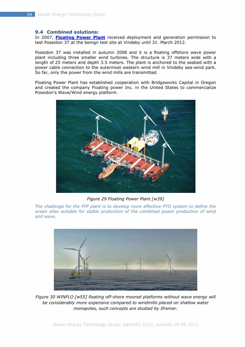
Ocean Energy Technology Study, DanWEC 2012, revision 10-09-2012
Ocean Energy Technology Study 34
9.4 Combined solutions: In 2007, Floating Power Plant received deployment and generation permission to
test Poseidon 37 at the benign test site at Vindeby until 31. March 2012.
Poseidon 37 was installed in autumn 2008 and it is a floating offshore wave power
plant including three smaller wind turbines. The structure is 37 meters wide with a
length of 25 meters and depth 3.5 meters. The plant is anchored to the seabed with a
power cable connection to the outermost western wind mill in Vindeby sea-wind park.
So far, only the power from the wind mills are transmitted.
Floating Power Plant has established cooperation with Bridgeworks Capital in Oregon
and created the company Floating power Inc. in the United States to commercialize
Poseidon's Wave/Wind energy platform.
Figure 29 Floating Power Plant [w39]
The challenge for the FFP plant is to develop more effective PTO system to define the
ocean sites suitable for stable production of the combined power production of wind
and wave.
Figure 30 WINFLO [w55] floating off-shore moored platforms without wave energy will
be considerably more expensive compared to windmills placed on shallow water
monopoles, such concepts are studied by Ifremer.

Ocean Energy Technology Study, DanWEC 2012, revision 10-09-2012
Ocean Energy Technology Study 35
9.5 Common challenges for selected Wave Energy technologies As part of the Danish Industrial Partnership project [17] and as derived from the ETI
Study in the UKREC [6], a number of common technological challenges for wave
power conversion have been identified.
In the order of importance, these areas are:
further develop the mooring systems
further develop PTO systems
further develop electrical transmission from floating structure to the sea-bed
materials and components
Moorings
Development of new mooring methods that with increased security and lifetime can be
established at reduced costs compared to conventional mooring systems. This should
include consideration to device size, extension to arrays, motions, power absorption
and how the device can sway around the mooring.
PTO power electronics
A WEC typically includes smaller generators (less that 1 MW) and a challenge is to find
the most cost effective way and most appropriate power technology in order to
interconnect the generators of the WEC (AC/DC to AC converter on the WEC) and of a
"farm" of WECs to a transformer station. This development would include the
assessment of efficiency, price, maintenance etc.
Power cable connection
The development and testing of a flexible electrical cable connection, which can be
used to connect a floating WEC, e.g. in such a way that it can turn around its mooring
point to a fixed point on the seabed. It is a challenge closely associated with the
mooring method, the plant size, water depth, bottom conditions and met-ocean
conditions.
Material and components
There is recognition of the need to develop and test new materials and components on
prototypes, in order to reduce costs and gain experiences regarding durability, anti-
fouling problems, corrosion etc. from the testing. Sharing such experience can help
accelerate the development.
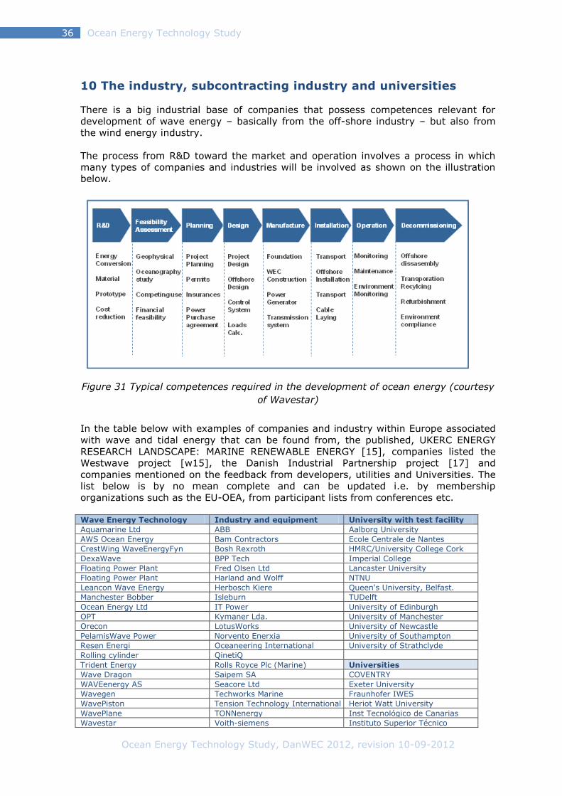
Ocean Energy Technology Study, DanWEC 2012, revision 10-09-2012
Ocean Energy Technology Study 36
10 The industry, subcontracting industry and universities
There is a big industrial base of companies that possess competences relevant for
development of wave energy – basically from the off-shore industry – but also from
the wind energy industry.
The process from R&D toward the market and operation involves a process in which
many types of companies and industries will be involved as shown on the illustration
below.
Figure 31 Typical competences required in the development of ocean energy (courtesy
of Wavestar)
In the table below with examples of companies and industry within Europe associated
with wave and tidal energy that can be found from, the published, UKERC ENERGY
RESEARCH LANDSCAPE: MARINE RENEWABLE ENERGY [15], companies listed the
Westwave project [w15], the Danish Industrial Partnership project [17] and
companies mentioned on the feedback from developers, utilities and Universities. The
list below is by no mean complete and can be updated i.e. by membership
organizations such as the EU-OEA, from participant lists from conferences etc.
Wave Energy Technology Industry and equipment University with test facility
Aquamarine Ltd ABB Aalborg University
AWS Ocean Energy Bam Contractors Ecole Centrale de Nantes
CrestWing WaveEnergyFyn Bosh Rexroth HMRC/University College Cork
DexaWave BPP Tech Imperial College
Floating Power Plant Fred Olsen Ltd Lancaster University
Floating Power Plant Harland and Wolff NTNU
Leancon Wave Energy Herbosch Kiere Queen's University, Belfast.
Manchester Bobber Isleburn TUDelft
Ocean Energy Ltd IT Power University of Edinburgh
OPT Kymaner Lda. University of Manchester
Orecon LotusWorks University of Newcastle
PelamisWave Power Norvento Enerxia University of Southampton
Resen Energi Oceaneering International University of Strathclyde
Rolling cylinder QinetiQ
Trident Energy Rolls Royce Plc (Marine) Universities
Wave Dragon Saipem SA COVENTRY
WAVEenergy AS Seacore Ltd Exeter University
Wavegen Techworks Marine Fraunhofer IWES
WavePiston Tension Technology International Heriot Watt University
WavePlane TONNenergy Inst Tecnológico de Canarias
Wavestar Voith-siemens Instituto Superior Técnico

Ocean Energy Technology Study, DanWEC 2012, revision 10-09-2012
Ocean Energy Technology Study 37
Weptos Kössler NUI Maynooth
Ceto Consultants Engineering Robert Gordon University
Bolt Areva Second University of Naples
Seabased Artemis Intelligent Power Ltd Swansea University
Atkins UCDublin
Tidal Energy Technology Black & Veatch UCL CIVIL
Ecopraxis Cummins Generation University of Bath
Lunar Energy Ecofys University of Bristol
Marine Current Turbines Edinburgh Designs Ltd University of Durham
Open Hydro Engineering Business University of Nottingham
Scot Renewables Garrad Hassan University of Oxford
SMD Hydrovision Halcrow University of Plymouth
Swan Turbines Innovayt University of Sheffield
Teamwork Technology Martek Limited University of Southampton
Tidal Generation Mojo Maritime Technical University Munich
Rambøll Technical University Warsaw
SPOK APS
Utilities Certification Network organisations Alstom DNV AOEA
DONG Energy Power A/S German Lloyd RenewableUK
E.ON Bølgekraftforeningen
E.ON Legal matter Donegal County Development
EDF Energy Philip Lee Solicitors Esbjerg Erhvervsudvikling
EDP Inovação Sandroos, advokatfirma EU-OEA
Ente Vasco de la Energia Green-Ofshore Alliancen
ESB International Hanstholm Havneforum
Fortum IEA Ocean Energy Group
Guernsey Electricity IMERC
Hydro Tasmania LORC
Iberdrola MEER
Npower renewables MRIA
Scottish renewables Renewable Energy Association
Scottish and Southern Energy West Wave
SSE Renewables
Vattenfall
Test tanks facilities Test sites at sea Technological institutes
HR Wallingford Ltd Bimep DHI
Ifremer DanWEC INETI
EMEC Marine Institute
NaREC (Test Facilities) NUIG Ryan Institute
Nissum Bredning TECNALIA-RBTK
Sem REV
WAVEHUB
Public organisations
Financial firms and banks
Carbon Trust
One51
DTI
Pershing International Nominees
Energinet.dk
Scottish Enterprise Seed Fund
Western Development Comm
Sigma Capital
Triodos Bank
Vækstfonden

Ocean Energy Technology Study, DanWEC 2012, revision 10-09-2012
Ocean Energy Technology Study 38
11 International market trends within the Ocean Energy
11.1 The technology trends The general market trends within ocean energy i.e. wave and tidal appear to be as
follows:
Today, the UK has leased sites of about 1 GW power projected to be 40 GW by 2050.
This represents a substantial market of thousands of devices constructed in waters
around the UK and elsewhere.
The international market for tidal stream energy is developing faster compared to
wave energy, most likely because the tidal structures can be located at sites not too
exposed to extreme wave conditions with a good resource – and in this way they are
more directly related to the technologies used in offshore wind today.
The rapid development of tidal stream technology is demonstrated by the many
promising device types at prototype stage operating at the EMEC test site [w9] such
as:
1. Open Hydro 250kW Open Centred tidal turbine deployed
2. Open Hydro – 600kW turbine deployed (not grid connected)
3. Tidal Generation Ltd 500kW tidal turbine deployed
4. Atlantis Resources Corporation AR1000 1 MW tidal turbine deployed
5. Scotrenewables SR250 floating tidal turbine deployed
6. Hammerfest Strom 1MW tidal turbine deployed
7. Voith Hydro tidal turbine
In addition, there is the 1,2 MW Seagen located in Northern Ireland [w9].
Concerning wave energy, the UK sites for about 600 MW has been leased and the
WECs currently being tested at EMEC are:
1. Pelamis P2 750 kW Machine (Eon)
2. Pelamis P2 750 kW Machine (Scottish Power Renewables)
3. Aquamarine Power Limited – Oyster 800 Stage 1
4. Wello Oy Penguin 500 kW wave converter
Based on the successful completion of these EMEC tests, the WECs will be tested
further in arrays to be deployed at the Wavehub site in southern UK.
Ocean Energy Technology Study, DanWEC 2012, revision 10-09-2012
Ocean Energy Technology Study 39
11.2 Implementing Agreement on Ocean Energy Systems (OES) The international trends within ocean energy development is best followed on the
home page for the Implementing Agreement on Ocean Energy Systems [w56] initiated
by Portugal, Denmark and the UK in 2001.
As of December 2011, 19 countries are members of the OES: Portugal, Denmark,
United Kingdom, Japan, Ireland, Canada, the United States of America, Belgium,
Germany, Norway, Mexico, Spain, Italy, New Zealand, Sweden, Australia, Republic of
Korea, South Africa and China.
The annual reports produced by the OEC and their website are informative and up to
date.
Trends within ocean energy can be monitored at dedicated conferences such as:
European Wave and Tidal Energy Conference (EWTEC)
International Conference on Ocean Energy (ICOE)
4th Global Marine Renewable Energy Conference (GMREC)
These conferences tend to get bigger and bigger.
11.3 Maritime Spatial Planning In the annual report from the OES 2011, [w6] there is an interesting article on the
need for Maritime Spatial Planning and the conclusions are referred below:
Maritime Spatial Planning (MSP) will have significant implications for the development
of marine renewable generally, and the ocean energy sector in particular. Economic
development and marine environmental protection have an equal weighting in the
EU’s Integrated Maritime Policy and both elements are either already specifically
addressed in legislation or will be in the near future. This means that it is essential for
the ocean energy industry to engage fully in the Maritime Spatial Planning process to
ensure that conflicts are minimised and that the industry can progress in a sustainable
manner. From an industry perspective, it is essential that research is undertaken to
understand the extent to which ocean energy developments can be deployed and co-
located with other users of the sea. This could help lessen the need for ‘exclusion
zones’ within MSP systems.
As a key player in the advancement of ocean energy, the Ocean Energy Systems
Implementing Agreement (OES) is in a unique position to encourage device and
project developers to involve themselves in the debates and processes surrounding
development of Maritime Spatial Planning systems in different jurisdictions. The
European Commission recognized that stakeholder participation will significantly raise
the quality of MSP. Developers already have a wealth of tacit knowledge from their
experiences of deploying devices. They know what has worked well and where. This
type of knowledge will help inform the creation of an MSP system that is both fully
reflective of the needs of the industry and will also enlighten other industries as to the
specific requirements of the ocean energy sector. The OES should promote this active
involvement of the sector, as it is an essential criterion for progress and acceptance of
MSP.
Ocean Energy Technology Study, DanWEC 2012, revision 10-09-2012
Ocean Energy Technology Study 40
11.4 Standards under IEC TC 114 On the technical side, standards on ocean energy are being prepared under the IEC TC
114 [w57] including so far:
IEC TC 114
Reference
Title
PT 62600-1 Terminology.
PT 62600-2 Design requirements for marine energy systems.
PT 62600-10 Assessment of mooring system for marine energy converters.
PT 62600-100 Power performance assessment of electricity producing wave
energy converters.
PT 62600-101 Wave energy resource assessment and characterization.
PT 62600-200 Power performance assessment of electricity producing tidal
energy converters
PT 62600-201 Tidal energy resource assessment and characterization.
PT 62600-102 Wave Energy Converter Power Performance Assessment at a
Second Location Using Measured Assessment Data.
11.5 Certification of Tidal and Wave Energy Converters DNV has a risk-based certification process for tidal and wave energy converters. This
process is defined in their OSS-312 Certification of Tidal and Wave Energy Converters.
The OSS-312 informs a generic list of documents and defines the extent of the scope
of certification. The certification is not only related to safety and environment, but to
functional requirements that are of key importance for the success of marine
renewables.
The certification process is a gradual process that evolves at the same level as the
technology evolves. This is reflected on the different certification deliverables, as part
of the initial steps of the certification process and its function of the results from the
technology assessment and failure mode identification and risk ranking; i.e. it is a
direct function of the criticality and associated risks to the success of the technology.
11.6 The EERA initiative One of the aims of the EERA Ocean Energy Joint Program [w58] is to promote the
incorporation of ocean energy into the SET-plan. The EERA Ocean Energy JP will also
provide a coordinated voice towards the European Commission and the member states
on medium to long term research priorities that are required in order to bring the
sector to successful commercial deployment levels.
The EERA Ocean Energy JP is based around six key research themes. These themes
have been developed based on existing research roadmaps which identify the critical
areas of research required for the successful growth of the industry.
The research themes are:
• Resource
• Devices and Technology
• Deployment and Operations
• Environmental Impact
• Socio-economic Impact
• Research Infrastructure, Education and Training
Within each research theme, a number of sub-topics have been identified as key long
term research objectives.

Ocean Energy Technology Study, DanWEC 2012, revision 10-09-2012
Ocean Energy Technology Study 41
Initial EERA Ocean Energy JP activities are not able to cover all of the objectives
identified but have been prioritized in the first year’s program by need and the current
availability of funding. The gap between, what has been identified as a key long term
objective, and what the EERA Ocean Energy JP is actually able to deliver in the first
year, will help identify issues that need future funding and coordinated research
efforts.
A key objective of the joint EERA program is to address the medium to long term
research challenges that the sector has identified in a variety of ocean energy
roadmaps such as the European Ocean Energy Association’s Oceans of Energy
Roadmap (2010) [], the UK DECC Marine Action Plan (2010) [w59], the Scottish
FREDS Marine Energy Roadmap (2009) [w60], the UKERC/ETI Marine Energy
Technology Roadmap (2010) [w61] and the UKERC Marine Renewable Energy
Technology Roadmap (2008) [w62]. The challenges identified in these roadmaps are
strongly reflected in the six key EERA ocean energy research themes.
Members of the EERA are as of March 2012 are: Germany, Italy, UK, Ireland, France,
Spain, Portugal, Norway and Denmark is in the process of joining.
11.7 European projects on Ocean Energy WavePlam (2007-2009) [w63] - The purpose of the WAVe Energy PLAnning and
Marketing project is to develop tools, establish methods and standards, and create
conditions to speed up introduction of ocean energy onto the European renewable
energy market.
EQUIMAR (2008-2011) [w3] – "Equitable Testing and Evaluation of Marine Energy
Extraction Devices in terms of Performance, Cost and Environmental Impact", EU 7FP
funded (STREP programme).
SOWFIA (2010-2012) [w64] - “Streamlining of Ocean Wave Farms Impact
Assessment” aims to facilitate the development of European wide, coordinated, unified
and streamlined environmental and socio-economic Impact Assessment (IA) tools for
offshore wave energy conversion developments. Wave farm demonstration projects
will be studied in each of the collaborating EU nations.
FAME (2010-2012) [w65] - “The Future of the Atlantic Marine Environment” - financed
by the EC INTERREG IV programme, with the aim to link the protection of natural
values, specifically biodiversity (avifauna) with economic activities at the European
Atlantic Ocean.
Aqua-RET2 (2009-2011) [w66] - “Dissemination activities and transfer of technology
in the ocean energy sector” (EU - Leonardo da Vinci - Lifelong Learning Programme).
ORECCA (2009-2011) [w67] - The goals of the ORECCA project (Off-shore Renewable
Energy Conversion Platforms – Coordination Action) are to create a framework for
knowledge sharing and to develop a roadmap for research activities in the context of
offshore renewable energy that are a relatively new and challenging field of interest.
CORES (2008-2011) [w68] - “Components for Renewable Ocean Energy Systems”. EU
7FP funded (RTD programme). This project concentrated on the development of a
toolbox of the wave to wire simulations to be applied to the OE Buoy Technology,
developed by the Irish company Ocean Energy Ltd.
WAVEPORT (2009-2012) [w69] - “Demonstration & Deployment of a Commercial
Scale Wave Energy Converter with an Innovative Real Time Wave by Wave Tuning
Ocean Energy Technology Study, DanWEC 2012, revision 10-09-2012
Ocean Energy Technology Study 42
System” (EU FP7 programme), with the aim to demonstrate a large scale grid
connected, 600kW peak rated, Powerbuoy Technology.
SURGE (2009-2011) [w70] - The European Project SURGE (Simple Underwater
Renewable Generation of Electricity) is funded by the EC under FP7 and intends to test
and assess the second generation of the Finnish WaveRoller device, near Peniche.
After testing the prototype WaveRoller1 at full-scale at the European Marine Energy
Centre (EMEC), in Scotland and in Portugal, AW-Energy, owner of the technology, will
install and test its second prototype in Portuguese waters.
MaRINET (2011-2015) [w71] - The aim of this project is to coordinate research and
development at all scales (small models through to prototype scales from Laboratory
through to Open Sea tests) and to allow access for researchers and developers into
facilities, which are not universally available in Europe.
TROPOS (2011-2015) [w72] - “Modular Multi-use Deep Water Offshore Platform for
Harnessing and Servicing Mediterranean, Subtropical and Tropical Marine and Maritime
Resources”. The aim is to develop a floating modular multi-use platform system for
use in deep waters.
MARINA (2010 - 2014) [w73] the MARINA Platform project will establish a set of
equitable and transparent criteria for the evaluation of multi-purpose platforms for
marine renewable energy (MRE).
H2OCEAN (2012 – 2014) [w71] H2OCEAN is a project aimed at developing an
innovative design for an economically and environmentally sustainable multi-use
open-sea platform. Wind and wave power will be harvested and part of the energy will
be used for multiple applications on-site, including the conversion of energy into
hydrogen that can be stored and shipped to shore as green energy carrier and a multi-
trophic aquaculture farm.
MERMAID (2012 – 2015) [w72] Innovative Multi-purpose off-shore platforms:
planning, Design and operation. Marine structures for offshore wind farms and
aquaculture have to be installed at various sites and on much larger scale than earlier
implementation of offshore structures in order to fulfil EU strategies (1) for reduction
of fossil-based energy and (2) to become a major player in sustainable aquaculture.
However the feasibility is much more sensitive to the costs of structures and the
installation of the structures than for instance Oil & Gas facilities.
Both for offshore renewables and for aquaculture a substantial part of the costs is
variable cost related to operations and maintenance of the plants. It is obvious that
optimization of the use of ocean space for different purposes might benefit from
shared resources such as staff allocation, transportation of staff and material from and
to the platforms, use of forecasting systems, ships etc.

Ocean Energy Technology Study, DanWEC 2012, revision 10-09-2012
Ocean Energy Technology Study 43
12 Selected examples of cooperation and synergies
Future development of the ocean energy sector will be linked with developments in
other sectors, such as offshore wind energy, exploiting positive synergies in
technology developments (e.g. components), infrastructure, supply chain and policies.
There will be significant opportunities for co-location of technologies; for example,
ocean energy and offshore wind energy, utilizing common platforms or wave/wave or
wind/tidal hybrid systems. Mutual learning processes, shared infrastructure and
innovations from a shared supply chain will be of great benefit to the future expansion
of both the ocean energy sector and related sectors
12.1 European Wavetrain 2 Project
01.01.2009 – 30.06.2012 The first example of synergies between different actors being mobilized within the
Ocean Energy industry is the Wavetrain program. Over the last decade, the Wavetrain
program co-ordinated by the Wave Energy Centre in Portugal has been successful in
bringing different companies together and integrate graduate students into the
research and development sphere of Ocean Energy.
The Wavetrain2 project is a multinational Initial Training Network (ITN) funded under
the FP7-People program, in order to face the wide range of challenges that industrial-
scale wave energy implementation faces in the near future, focusing on technical
issues, from hydrodynamic and PTO (Power Take-Off) design, to instrumentation
issues and energy storage and cost reduction which are critical for successful
deployment. On the other hand, also non-technical “barriers”, typically less tangible
difficulties related to legal issues (licensing, conflicts of use, EIA procedures, grid
connection, regional differences) and the non-sufficient representation of socio-
economic benefits of the sector, is dealt with, as they are seen as a major obstacle for
fast implementation on a European scale. The network consists of 13 European
partner institutions and 17 associated entities, from research units and device
developers to project developers and consultants.
Figure 32 Wavetrain2 fellows http://www.wavetrain2.eu
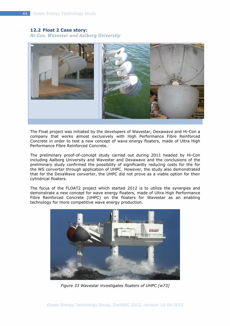
Ocean Energy Technology Study, DanWEC 2012, revision 10-09-2012
Ocean Energy Technology Study 44
12.2 Float 2 Case story:
Hi-Con, Wavestar and Aalborg University
The Float project was initiated by the developers of Wavestar, Dexawave and Hi-Con a
company that works almost exclusively with High Performance Fibre Reinforced
Concrete in order to test a new concept of wave energy floaters, made of Ultra High
Performance Fibre Reinforced Concrete.
The preliminary proof-of-concept study carried out during 2011 headed by Hi-Con
including Aalborg University and Wavestar and Dexawave and the conclusions of the
preliminary study confirmed the possibility of significantly reducing costs for the for
the WS converter through application of UHPC. However, the study also demonstrated
that for the DexaWave converter, the UHPC did not prove as a viable option for their
cylindrical floaters.
The focus of the FLOAT2 project which started 2012 is to utilize the synergies and
demonstrate a new concept for wave energy floaters, made of Ultra High Performance
Fibre Reinforced Concrete (UHPC) on the floaters for Wavestar as an enabling
technology for more competitive wave energy production.
Figure 33 Wavestar investigates floaters of UHPC [w73]

Ocean Energy Technology Study, DanWEC 2012, revision 10-09-2012
Ocean Energy Technology Study 45
13 Information exchange
The request for information has been send to the organisations indicated in the table
below and the response and information received has been helpful and is greatly
appreciated.
Company Contact Question
guide send
Information
received
Interview
Danish developers: Wavestarenergy Laurent Marquis 2012-03-09 2012-03-16 2012-03-16
FPP Anders Krøhler 2012-03-09
DEXA Lars Elbæk 2012-03-09 2012-03-12
Wave Dragon Erik Friis-Madsen 2012-03-09 2012-03-30
Crestwing Henning Pilgaard 2012-03-09 2012-03-12
Leancon Kurt D Rasmussen 2012-03-09 2012-03-14 2012-03-14
Weptos Tommy Larsen 2012-03-09 mail
Wave Piston Martin von Bülow 2012-03-09 2012-03-13 2012-03-13
Roling cylinder Inventua Aps
Lars Ingerslev
2012-03-09
Developers abroad: Pelamis Wave Richard Yemm,
Chris Retzler 2012-03-12
2012-04-26
Oyster, Aquamarin Charlotte Taylor 2012-03-27
Seabased Mats Leon 2012-03-12
Wavebob Jochem Weber 2012-03-12
OE-bouy Mike Whelan 2012-03-12
AWS Simon Gray 2012-03-12
Bolt Tore Gulli 2012-03-12 2012-03-20
CETO Greg Allan 2012-03-29 2012-03-31
WaveGen Tom Heath 2012-03-27 2012-04-27
Universities
AAU,
Peter Frigaard, Jens Peter Kofoed
2012-03-09 2012-04-
ECN Alain Clement Aurélien Babarit
2012-03-09 2012-03-14 2012-03-14
ITS, Antonio Sarmento 2012-03-09 2012-03-12
UCC HMRC,
Gareth Thomas Brian Holmes Tony Lewis
2012-03-09 2012-04-06 2012-04-06
UEDIN, Stephen Salter 2012-03-09 2012-04-11 2012-04-26
Queens Trevor and Cuan 2012-03-09
NTNU Jorgen Hals Torgeir Moan
2012-03-27
Utilities
Vattenfall; Per Holmberg Bjorn Bolund
2012-03-09 2012-03-21
DONG, Jon Vindahl Kringelum
2012-03-09 2012-03-21 2012-03-22
ESBI 2012-03-28 2012-03-12
E-on, David Futter 2012-03-27
Scottich renewable, Johanna Yates
DNV Claudio Bittencourt 2012-03-28 2012-04-09
Ocean Energy Technology Study, DanWEC 2012, revision 10-09-2012
Ocean Energy Technology Study 46
12.1 Utilities DONG Energy represented by Jon Vindahl Kringelum, ESB Ireland represented by
James Tedd and Vattenfall Per Holmberg and Bjorn Bolund have responded to our
questionnaires, and their responds to each question is summarized below.
HOW IS THE SCREENING OF THE OCEAN ENERGY MARKET DONE?
DONG Energy is following the development of Ocean Energy, including available
support regimes within their geographical focus area (NW-Europe). DONG Energy is
especially interested in technologies that have synergies with Offshore Wind and is
only focusing on wave currently.
In that respect DONG Energy is looking at available wave resource near their existing
and future wind projects and the available resources in general.
On the technical side DONG Energy do screening of wave concepts internally, but not
with any fixed frequency.
ESB has used a dedicated technical evaluation process (See WestWave Supply Chain
Appendix 2 at http://www.westwave.ie/contact_us/) to determine a Technology
Readiness Level (TRL) for each technology.
A hurdle of TRL8, which requires at least a single prototype of the machine to have
been deployed and operated, has been set as the maturity required to be a candidate
technology for WestWave the early array project ESB are leading.
ESB have also provided technical support to technologies at TRL 5-7 through support
on Safety, Power Quality, Electrical Engineering etc.
Vattenfall has since 2006 screened the ocean energy technology options in terms of
technical readiness. Vattenfall’s strategy is to engage with those technologies that are
approaching readiness for wave farm deployment, and fit their business requirements.
The level of engagement increases with readiness.
Early stage technologies (TRL4-5) are continuously monitored by Vattenfall using
various means such as conferences, relevant newsletters and home pages. For those
technologies that are more mature, Vattenfall (TRL5-6) have also regularly been in
direct contact with the technology developers to receive and review their material. As
the developers approach readiness (TRL6-7) Vattenfall requests specific technical
information based on their template to evaluate technically. Once Vattenfall have
decided that a technology will likely become viable they contract the firm to allow
technical due diligence and propose projects. This has happened with one company.
Vattenfall also has close contact with other stake holders such as authorities and trade
organizations mainly in UK but also in the rest of Europe.

Ocean Energy Technology Study, DanWEC 2012, revision 10-09-2012
Ocean Energy Technology Study 47
WHAT TYPE OF CONCEPTS RECEIVES SUPPORT AND WHY?
DONG Energy has partnership agreements with 2 Danish concepts, but are not
providing any financial or investment support.
1. Floating Power Plant, where Dong Energy is supplying infrastructure for
connection to their Vindeby Wind Farm
2. Wave Star, where the company has an R&D partnership agreement
ESB work closest together with the companies who have developed their concepts
closest to commercialization.
Vattenfall decided at an early stage to focus on deep water wave devices as they
judged the potential to be large and the consenting process easier (i.e. scalability). As
a utility Vattenfall is a procurer and operator, i.e. not developer, of technology and
therefore mainly interested in wave power converters in advanced stages of
development. As of now Vattenfall is collaborating closely with Pelamis ltd. that in
their judgment has a sound technology as well as being the most mature concept from
a development perspective. Vattenfall is also following the development of a number
of deep water concepts that are promising.
REQUIREMENTS FOR VALIDATION/DEMONSTRATION SCALE?
DONG Energy is in general open to participate in demonstration projects, however at
the moment they are focused on their 2 existing partnerships. Demonstration at their
existing sites requires a track-record of prior successful offshore testing and a very
high level of safety, both regarding personnel and the device itself.
ESB: There is a need for public funding to bring technologies through to a stage where
utilities such as ESB can be involved. This includes all the stages up to TRL 8, and at
that stage grant and tariff support is required.
Vattenfall uses a Technology Readiness Scale (TRL) with 9 levels (from idea=1 to
commercial readiness=9). Preferably Vattenfall would like to see concepts proven in
full scale in operational conditions (TRL 8) but acknowledging the immaturity of the
sector the company takes active interest at an earlier stage. Generally Vattenfall's
minimum requirement is for the concept to have been proven in the sea in, say 1:10
to quarter scale, with power generation (TRL 6-7). Vattenfall also expect the
development to have followed the preceding steps with e.g. validation of
hydrodynamic performance through both tank tests and numerical modeling.
PROSPECTS OF INCLUDING OCEAN ENERGY IN YOUR BUSINESS PLAN
DONG Energy: Wave Energy is currently not a part of DONG Energy's business plans.
To achieve that, Devices developers have to prove a long continuous period of energy
production offshore without major failures or unavailability. Also there must be a
proven and documented prospect of driving down the Cost of Energy to a competitive
level.
ESB has an Ocean Energy Team with the target to develop the capability to deliver
Utility Scale Ocean Energy Projects. In the short term ESB is leading the WestWave
project to deliver Ireland’s first grid connected 5 MW wave energy array.
Vattenfall already has an ocean energy business plan, since 2006, as part of its R&D
Projects portfolio. If the development can fulfill Vattenfall's requirements on technical
and economic performance Vattenfall expect wave power to be a future part of
Vattenfall’s renewable energy portfolio.

Ocean Energy Technology Study, DanWEC 2012, revision 10-09-2012
Ocean Energy Technology Study 48
WHAT PERCENTAGE OF FUTURE ENERGY PRODUCTION WILL COME FROM
OCEAN ENERGY?
DONG Energy: This is not possible to say at the moment.
ESBI: There is great potential on the western seaboard of Europe for generation from
Ocean Energy. There have been numerous studies on this which would be the best
references to use.
Vattenfall’s ocean energy business plan models 1000MW and 500MW deployment
scenarios by 2030. The achievement of these scenarios is entirely dependent on
development of the technology and market enablers. We cannot predict the installed
capacity beyond 2030. Vattenfall’s overall electricity production is currently in the
order of 180TWh.

Ocean Energy Technology Study, DanWEC 2012, revision 10-09-2012
Ocean Energy Technology Study 49
12.2 Universities This section includes the response to our questionnaires from António Sarmento IST in
Portugal, Alain Clement and Aurélien Babarit at Ecole Centrale de Nantes (ECN) in
France, Garreth Thommas at University College Cork (UCC) Ireland, Peter Frigaard at
Aalborg University (AAU) in Denmark and David Forehand at University of Edinburgh
(UEDIN)
WHAT THEORETICAL AND NUMERICAL TOOLS ARE USED TO MODEL THE
POWER PRODUCTION FROM WAVE POWER DEVICES?
IST: The state-of-the-art are time-domain models based in the linear theory to
estimate the forces due to wave-structure interactions. However these models use
non-linear sub-models to simulate the performance of the electromechanical power
take-off equipment and the control laws. Most often the mooring forces are also
treated linearly (quasi-static). In the most advanced state-of-the-art models the
impulse response functions needed to include the memory effects of the wave-
structure interactions are replaced by state-space approaches. Non-linear
hydrodynamic models for the wave-structure interactions exist but are no standard
(and require much more simulation time). Overtopping devices are typically more
difficult to model as the overtopping is a high non-linear approach, which is simulated
by empirical formulae.
ECN: It depends on the desired level of accuracy:
1. To make a quick and dirty estimate of the power absorption of a particular
WEC, we will make use of the typical Capture Width Ratio (CWR) for the category into
which falls the WEC. Basically, we will identify the working principle of the WEC, will
look in the table in [Babarit and Hals, 2011] and based on the characteristic length or
width of the device, we will calculate the power.
2. A more refined approach will be to develop a numerical Wave to Wire (W2W)
model, the wave structure interaction being modeled using linear potential theory. It
will make use of one of the usual BEM solver such as WAMIT, Aqwa, Aquaplus, … More
details can be found in [Bhinder et al., 2010]
3. For modeling specific details, CFD codes might be requested. However, we
don’t believe that they are suitable for assessing the power production from wave
power devices. Mostly because of CPU time, but also because it is well known that
there have issues with propagating accurately gravity waves.
UCC: Wammit, Mathlab (simulate toolbox), Mathematica, Numerical wave tank, Survil
conditions simulated using CFD Second order – non-linear models.
AAU: Simple dynamic models. Wamit, Shipbem, CFD programmes like CFX, Fluent,
Star, Open Foam, Naval Foam etc…
UEDIN: Firstly, I should state that I am only talking about numerical models that are
used in Edinburgh University, other numerical models also exist.
From a hydrodynamic point of view, we use the commercial frequency-domain code
WAMIT to model the response of both single and multiple devices. This is a
radiation/diffraction code which assumes linear (Airy) waves and small body motions.
Using hydrodynamic data from WAMIT (wave excitation and added mass and damping
coefficients), an in-house, time-domain, hydrodynamic WEC array model has been
developed at Edinburgh. This code can model transient behaviour and allows the
inclusion of nonlinear external forces, such as nonlinear PTO and mooring forces. The
time-domain model uses a state-space approach to replace the difficult radiation
convolution terms.
Ocean Energy Technology Study, DanWEC 2012, revision 10-09-2012
Ocean Energy Technology Study 50
Edinburgh University researchers are also members of the international Wave Energy
Converter Array Network (WECAN). This network of researchers has recently written
a review paper on numerical hydrodynamic modelling techniques for arrays of wave
energy converters but it also applies to individual devices. The title of this review
paper is “A Review of Numerical Modelling of Wave Energy Converter Arrays” and it
will be presented at the OMAE conference held in Rio de Janeiro, Brazil in June 2012.
The time-domain array model developed at Edinburgh has also been incorporated into
a larger Edinburgh wave-to-wire model. This wave-to-wire code can simulate
directional, irregular seas. In addition, it can model hydraulic PTOs in each device as
well as the offshore and onshore electrical network. The model is truly bi-directional,
in that disturbances in the sea can be seen in the electrical network and vice-versa.
HOW WELL CAN YOU ENSURE MODEL ACCURACY (E.G., BY USING
LABORATORY TEST/WATER TANK/WAVE BASINS)?
IST: The state-of-the-art numerical simulation models are relatively accurate in small
waves but not so much in high waves, it being critical for survivability conditions
(extreme waves). In those cases non-linear and possibly viscous models need to be
use. In very resonance conditions (sinusoidal waves close to the resonance frequency
leading to very large device excursions) state-of-the-art models are also not accurate.
ECN: W2W model must be validated against scale model tests. In ECN, a large wave
basin is available (50m long, 30m wide, 5m deep, 48independent wavemakers) for
that purpose. Usual scale is 1/10 to 1/20 to validation tests.
ECN References:
1. A. Babarit, J. Hals, 2011. On the maximum and actual capture width
ratio of wave energy converters. In Proc. Of the 9th European Wave and Tidal
Energy Conference, Southampton, UK.
2. M. Bhinder, M. Guerinel, M. Alves, A. Sarmento, A. Babarit, 2010. State
of the art Report WP1 – Numerical Hydrodynamic Modeling of Wave Energy
Converters. Deliverable D2 of the Wavetrain2 EU project
UCC: Viscosity, important, in small scale. Pretty good today in measuring what's going
on in the basin. Several scales, suggest to incorporate as a standard numerical
modeling with experiments to get a feeling of the accuracy. Do you simulate what you
intend - using model tests. Marinet, course on how to model test wave energy
systems,
AAU: The answer depends on the scale and the purpose of the testing.
In a typical testing in scale 1:30, forces like mooring forces can be measured and up
scaled with an accuracy better than plus/minus 2%. Overtopping can be measured
and up scaled with an accuracy better than plus/minus 5-10%. Energy production
(including control systems) is typically the big problem. If the PTO system is simply
scaled, a typical accuracy can be as low as plus/minus 30%. Therefore PTO systems
are normally not just scaled but modeled in such a way that their effects on
movements are modeled correct.
UEDIN: The results of the hydrodynamic time-domain array model have been tested
against those of WAMIT for situations where both approaches are valid (i.e. “steady-
state” oscillations). The results of the hydrodynamic time-domain array model are also
going to be compared against tank test results. Edinburgh University researchers are
part of a European team who will be performing tank testing on arrays of model wave
energy devices in DHI’s wave basin later this year. These test have been entitled
“WECwakes” and they are being funded by EU’s Hydralab IV programme.

Ocean Energy Technology Study, DanWEC 2012, revision 10-09-2012
Ocean Energy Technology Study 51
12.3 Standardisation / certifying authorities Concerning Standardisation and certification DNV has been contacted, represented by
Claudio Bittencourt who has provided the information below.
LEVEL OF DOCUMENTATION CONCERNING MAIN REQUIREMENTS FOR OCEAN
ENERGY DEVICES
DNV has a risk-based certification process for tidal and wave energy converters. This
process is defined in our OSS-312 Certification of Tidal and Wave Energy Converters.
The OSS-312 informs a generic list of document and defines the extent of the scope of
certification. The certification is not only related to safety and environment, but to
functional requirements that are key for the success of marine renewables.
Thus, the documentation required for certification is related to the wide range of
aspects (from load derivation and interaction between power take-off and structural
response to power performance). Nevertheless, this documentation is no different to
what the developer / designer needs to generate to define and confirm satisfactory
performance of the technology.
The extent and depth of documentation required is confirmed on a technology by
technology basis as part of the initial steps of the certification process and is function
of the results from the technology assessment and failure mode identification + risk
ranking; i.e. it is a direct function of the criticality and associated risks to the success
of the technology.
The certification process is a gradual process that evolves at the same level as the
technology evolves and this is reflected on the different certification deliverables. The
OSS-312 will be revised soon, but the process described there and principles are still
valid.
SPECIFIC REQUIREMENTS FOR WAVE ENERGY TECHNOLOGIES
The main specific requirement is to perform the initial steps of the certification process
that involves the definition of the certification basis (i.e. all elements that defines the
limitations and boundaries of the technology and what are its targets), technology
assessment (for identification of degrees of novelty of the technology) and the failure
mode identification and risk ranking (that allows to identify what are the failure
modes, how critical they are and what is necessary to do to deal with them, i.e. to
mitigate the risks).
As there is a large diversity of concepts for wave energy conversion, there is no single
or simple specific special requirements that can be highlighted except for the fact that
the needs to the certification process are related to the assurance of the overall
performance of the technology.
Naturally, for floating devices (wave or tidal) there are special attention to be paid to
export power cable, the mooring analysis (considering the power take-off), fatigue
aspects, corrosion stability and water tightness, installation methodology and
derivation of power performance.

Ocean Energy Technology Study, DanWEC 2012, revision 10-09-2012
Ocean Energy Technology Study 52
Appendix I Sources of Ocean Energy
Wave Energy Wave energy [w74] is the energy contained in the waves generated by the wind on
the surface of the sea and the associated motion of the ocean extending down below
the sea surface down about a quarter of a wavelength.
Not surprisingly, the largest wave recourses are found on the middle of the northern
and southern hemisphere where the winds are strongest. Waves generated in one
location can on deep water travel long distances with little loss of energy, until waves
approach shallow water regions and coastlines where the energy is dissipated, through
bottom friction and wave breaking and power levels reduce.
The annual average wave power level in kW/m on different locations can be seen on
the map Figure 34.
Figure 34 Average annual Wave Power levels expressed in kW/m in the Oceans
(Oceanor)
Waves are predictable from weather forecasts. Based on satellite information and
meteorological models, the wave conditions at a certain location can be predicted with
reasonable accuracy about 6 – 8 hours in advance.
Finally, the wave energy resource can be harvested not too far off the coast of many
countries as can be seen on the map. In fact, the length of the coastline multiplied
with the power level can help give an estimate of the wave energy resource.
Even though waves appear similar, the wave conditions at selected location can be
quite different in terms of the statistical distribution of sea-states. Some ocean areas
such as the North Sea is dominated by steeper waves compared to the waves further
south such as off the coast of Portugal where the waves are dominated by swells, as
described in the OES -Task 2.1 report [14]. The highest waves at the site, the site
specific tidal variations and current conditions must be considered in the design of the
applied ocean energy technology.

Ocean Energy Technology Study, DanWEC 2012, revision 10-09-2012
Ocean Energy Technology Study 53
Tidal Energy Tidal energy [w75] is the energy associated with the tides created by the relative
forces and motions between the sun, moon and earth and the rotation of the earth.
The tides are therefore predictable in time, as periodic events visible in terms of high
and low water conditions once or twice a day.
Associated with the tidal water level variation are tidal streams or currents which can
have significant speeds depending on location. Tidal Streams are characterized by high
maximum speed (more than 2m/sec) and by changing direction once or twice a day
depending on the location and tidal variation at the site. Tidal energy can be utilized
by tidal barrage - or tidal stream systems.
Tidal Barrage
• Tidal barrage systems that utilize the difference in water level variation during
high and low tides in combination with dams and reservoirs.
There are a definite number of sites where tidal barrages can be build, in connection
with natural estuaries, the most well known is the La Rance 240 MW plant in France
which has been in operation since 1965. In Korea, the Shiwa 250 MW tidal plant is
under construction and other sites such as Bay of Fundy in Canada and the Severn in
the UK under consideration.
Tidal Stream
• Tidal Stream, systems that convert the flow of water – much like windmills
convert the flow of air.
Tidal stream sites are often found at places where the speed of water flow is increased
by local bathymetry and narrow sounds between islands.
Locations with high tidal variations Concentrated tidal streams locations
Figure 35 The potential sites for Tidal energy within Europe is located in the UK,
Ireland, France and Norway [w66]

Ocean Energy Technology Study, DanWEC 2012, revision 10-09-2012
Ocean Energy Technology Study 54
Ocean Currents Ocean currents are very characteristic flow patterns in the oceans. Some of these
currents are created and driven by the winds and some by the differences in water
density. Compared to tidal streams, the ocean currents maintain the same direction
and their speed is typically much lower and therefore expected to be more expensive
to convert into electricity.
Surface Currents
The world’s prevailing winds help bringing the warm air from the equatorial zones
towards the poles. The winds create giant circular currents patterns in the major
ocean basins (like gyres). Subtropical high-pressure areas (at around 30° latitude)
drive these gyres. Coriolis forces cause water in motion to be pulled to the right in the
northern hemisphere and to the left in the southern hemisphere.
Figure 36 Major Ocean Surface currents
Deep Ocean Currents
Currents created by differences in water density are sometimes called the ocean
“Great Ocean Conveyor Belt.” This circulation helps transporting heat from the equator
towards the poles, as shown on figure 5, and as such other vital principle of nature.
Cold or salty water is denser and sinks, whereas warm or less salty water is less dense
and rises. In Polar regions, much of the ocean water is tied up in ice sheets. The salt
remains in the liquid water, so the water in these areas is very salty, as well as very
cold. This water is consequently very dense and sinks. It is replaced by water from
lower latitudes. The deep, dense water then moves slowly across the ocean floor and
eventually rises in warmer latitudes.
Figure 37 Great Ocean Conveyor Belt [w76]
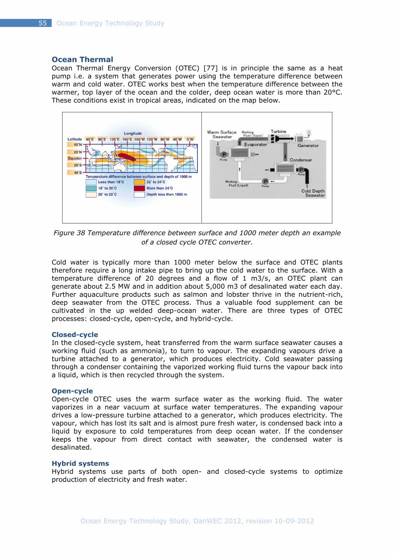
Ocean Energy Technology Study, DanWEC 2012, revision 10-09-2012
Ocean Energy Technology Study 55
Ocean Thermal Ocean Thermal Energy Conversion (OTEC) [77] is in principle the same as a heat
pump i.e. a system that generates power using the temperature difference between
warm and cold water. OTEC works best when the temperature difference between the
warmer, top layer of the ocean and the colder, deep ocean water is more than 20°C.
These conditions exist in tropical areas, indicated on the map below.
Figure 38 Temperature difference between surface and 1000 meter depth an example
of a closed cycle OTEC converter.
Cold water is typically more than 1000 meter below the surface and OTEC plants
therefore require a long intake pipe to bring up the cold water to the surface. With a
temperature difference of 20 degrees and a flow of 1 m3/s, an OTEC plant can
generate about 2.5 MW and in addition about 5,000 m3 of desalinated water each day.
Further aquaculture products such as salmon and lobster thrive in the nutrient-rich,
deep seawater from the OTEC process. Thus a valuable food supplement can be
cultivated in the up welded deep-ocean water. There are three types of OTEC
processes: closed-cycle, open-cycle, and hybrid-cycle.
Closed-cycle
In the closed-cycle system, heat transferred from the warm surface seawater causes a
working fluid (such as ammonia), to turn to vapour. The expanding vapours drive a
turbine attached to a generator, which produces electricity. Cold seawater passing
through a condenser containing the vaporized working fluid turns the vapour back into
a liquid, which is then recycled through the system.
Open-cycle
Open-cycle OTEC uses the warm surface water as the working fluid. The water
vaporizes in a near vacuum at surface water temperatures. The expanding vapour
drives a low-pressure turbine attached to a generator, which produces electricity. The
vapour, which has lost its salt and is almost pure fresh water, is condensed back into a
liquid by exposure to cold temperatures from deep ocean water. If the condenser
keeps the vapour from direct contact with seawater, the condensed water is
desalinated.
Hybrid systems
Hybrid systems use parts of both open- and closed-cycle systems to optimize
production of electricity and fresh water.

Ocean Energy Technology Study, DanWEC 2012, revision 10-09-2012
Ocean Energy Technology Study 56
Osmotic power Salinity gradient power or osmotic power [w78] is the power retrieved from the
osmotic pressure difference in salt and fresh water. Osmotic power is a large
renewable source of power - water evaporates from the surface of the sea, falls as
rain on the continents and returns to the sea. Every m3/s of fresh water that runs into
the sea can produce about 1 MW of osmotic power.
Two practical methods for generating power from the salt gradient are Reverse Electro
Dialysis (RED), and Pressure Retarded Osmosis (PRO). Technologies have been
confirmed in laboratory conditions and are being developed for commercial use.
Wetsus, a Dutch company, investigating reverse electrodialysis principles, has set-up
an experimental installation in Harlingen. This pilot project is based on the RED Stack
technology.
Statkraft in Norway completed a 10 kW prototype in 2009 to demonstrate the PRO
technology.
So far, the cost of the membrane has been an obstacle, however, further research into
membrane technologies can provide prospects for potential commercial use in the
future.
Figure 39 Principle of Osmotic power process PRO
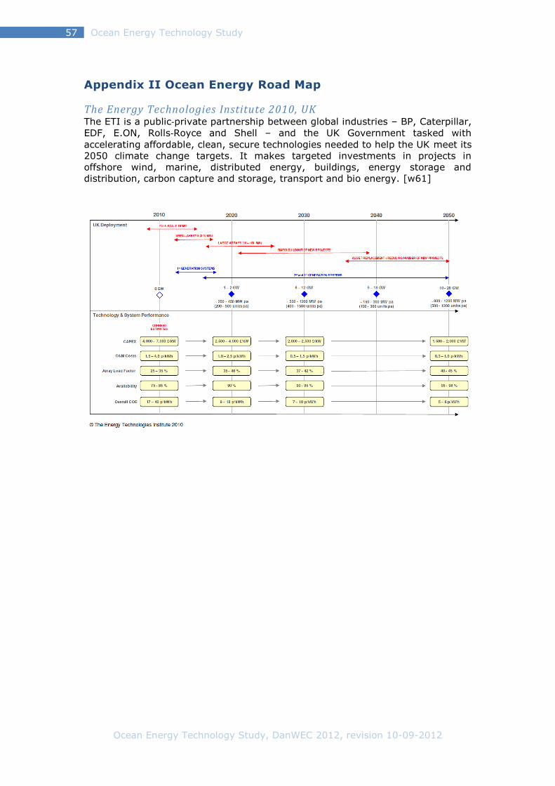
Ocean Energy Technology Study, DanWEC 2012, revision 10-09-2012
Ocean Energy Technology Study 57
Appendix II Ocean Energy Road Map
The Energy Technologies Institute 2010, UK The ETI is a public‐private partnership between global industries – BP, Caterpillar,
EDF, E.ON, Rolls‐Royce and Shell – and the UK Government tasked with
accelerating affordable, clean, secure technologies needed to help the UK meet its
2050 climate change targets. It makes targeted investments in projects in
offshore wind, marine, distributed energy, buildings, energy storage and
distribution, carbon capture and storage, transport and bio energy. [w61]
Ocean Energy Technology Study, DanWEC 2012, revision 10-09-2012
Ocean Energy Technology Study 58
References
1. Lewis, A., S. Estefen, J. Huckerby, W. Musial, T. Pontes, J. Torres‐Martinez, 2011:
Ocean Energy. In IPCC Special Report on Renewable Energy Sources and
Climate Change Mitigation [O. Edenhofer, R. Pichs‐Madruga, Y. Sokona, K.
Seyboth, P.Matschoss, S. Kadner, T. Zwickel, P. Eickemeier, G. Hansen, S.
Schlömer, C. von Stechow (eds)], Cambridge University Press, Cambridge, United
Kingdom and New York, NY, USA.
2. Mueller, M., and H. Jeffrey (2008). UKERC Marine (Wave and Tidal Current)
Renewable Energy Technology Roadmap: Summary Report. UK Energy
Research Centre, University of Edinburgh, Scotland.
3. T.W. Thorpe, (2010) Survey of Energy Resources, World Energy Council,
(section on Wave energy)
4. Holmes, B., and K. Nielsen (2010). Guidelines for the Development & Testing
of Wave Energy Systems. HMRC Hydraulics Maritime Research Centre report for
OES-IA, Report T02-2.1, OES-IA Annex II: Task 2.1, Implementing Agreement for
a Co-operative Programme on Ocean Energy Systems (OES-IA), Cork, Ireland.
5. Bahaj, A. S., L. Blunden and A. A. Anwar (2008) University of Southampton. OES
IA Annex II Task 2.2 Tidal Energy Development Protocol, Report from BERR for
the OES-IA.
6. Marine Energy Technology Roadmap, October 2010, Energy Technologies Institute
& UK Energy Research Centre
7. Offshore Wave Energy Converter Project, OWEC-1, March 1996, Danish
Wave Power Aps. Jou2 CT93-0394
8. Nielsen. K (2002) Bølgekraftprogram, Bølgekraftudvalgets afsluttende
rapport . s.l. : Bølgekraftudvalgets sekretariat, Energistyrelsen
9. Babarit A. , J. Hals, M.J. Muliawan, A. Kurniawan, T. Moan, J. Krokstad (2012),
Numerical benchmarking study of a selection of wave energy converters.
Renewable Energy 41
10. Mirko Previsic, Roger Bedard and George Hagerman (2004) E2I EPRI Assessment
- Offshore Wave Energy Conversion Devices, Report: E2I EPRI WP – 004 – US
– Rev 1
11. Appendix 2 Technology Readiness Levels for Supply Chain Study for WestWave
12. Accelerating marine energy, July 2011, The potential for cost reduction –
insights from the Carbon Trust Marine Energy Accelerator,
13. Kim Nielsen, (2003) RAMBOLL, Denmark, IEA | OCEAN ENERGY SYSTEMS: ANNEX
II Development of recommended practices for testing and evaluating
ocean energy systems
14. K. Nielsen & T. Pontes (2010) Report T02-1.1 OES IA Annex II Task 1.2 Generic
and Site-related Wave Energy Data.
15. Mueller, M., (2009) UKERC ENERGY RESEARCH LANDSCAPE: MARINE
RENEWABLE ENERGY, University of Edinburgh, Scotland.
16. Hanstholm Phase 2B, Offshore wave energy test 1994-96, Danish Wave Power Aps, Project report, 1996
17. J. Krogh, K. Nielsen, N. E. H. Jensen, J. P. Kofoed, E. Friis-Madsen, B. V.
Mikkelsen, A. Jensen, Strategi for forskning, udvikling og demonstration
2012, Partnerskabet for Bølgekraft, EUDP-2010-II J. nr. 64010-0472

Ocean Energy Technology Study, DanWEC 2012, revision 10-09-2012
Ocean Energy Technology Study 59
Web based references:
W1 Satellite images
http://www.goes.noaa.gov/goesfull.html
W2 Pelamis
http://www.pelamiswave.com/
W3 Eguimar project Proceedings and Protocols:
https://www.wiki.ed.ac.uk/download/attachments/9142387/Protocols-A4-
Downlaod.pdf?version=1
http://www.equimar.org/high-level-equimar-protocols-.html
W4 ESBI Appendix 2 Technology Readiness Levels for Supply Chain Study for
WestWave:
http://www.westwave.ie/wp-content/uploads/downloads/2011/12/Appendix-
2.pdf
W5 COE Energinet.dk
http://www.energinet.dk/SiteCollectionDocuments/Danske%20dokumenter/F
orskning/Bølgekraft_COE_beregningsark.xls
W6 OES, IEA Annual reports:
http://www.ocean-energy-systems.org/library/annual_reports/
W7 Crown Estate 2010 the successful bidders for sites in Scotland’s Pentland Firth
and Orkney
http://www.thecrownestate.co.uk/news-media/news/2010/worlds-first-wave-
and-tidal-energy-leasing-round/
http://www.energyefficiencynews.com/articles/i/2899/
W8 Oyster Aquamarine
http://www.aquamarinepower.com/projects/oyster-800-project-orkney/
W9 EMEC
http://www.emec.org.uk/
W10 Seagen
http://www.seageneration.co.uk/
W11 Ocean Energy Deployment Unit
http://www.seai.ie/Renewables/Ocean_Energy/OE_Engineering_Support_Req
uirements/Engineering_Specialist_Support_Requirements_for_OE_Sector.pdf
W12 ESBI
http://www.esbi.ie/
W13 Wavebob
http://www.wavebob.com/
W14 OE Buoy
http://www.oceanenergy.ie/
W15 West Wave Project
http://www.westwave.ie/
W16 Open Hydro
http://www.openhydro.com/home.html
W17 CETO
http://www.carnegiewave.com/index.php?url=/ceto/what-is-ceto
W18 BELUGA 9
http://www.alstom.com/press-centre/2010/12/alstoms-ocean-energy-
business-established-at-nantes/
W19 Sem-rev testsite
http://www.semrev.fr/en/en-presentation
W20 Sea-rev
http://192.107.92.31/test/owemes/29.pdf
W21 Maritime Portuguese Pilot Zone for Wave Energy Conversion
http://www.wavec.org/client/files/Izan_Le_Crom_et_al_paper.pdf
w22 Pico plant, OWC, Azores
http://www.wavec.org/index.php/34/owc-pico-plant/

Ocean Energy Technology Study, DanWEC 2012, revision 10-09-2012
Ocean Energy Technology Study 60
w23 AWS Netherlands
http://www.teamwork.nl/en/portfolio/project/archimedes-wave-swing
W24 OPT USA
http://www.oceanpowertechnologies.com/
W25 WaveRoller Finland
http://www.aw-energy.com/
W26 IST
http://www.master.eurec.be/en/Partnering-Universities/Spe-Ocean-Energy-
IST-Lisbon-Portugal/
W27 Wave Energy Center
http://www.wavec.org/
W28 Mutriku OWC
http://www.wavegen.co.uk/news_mutriku.htm
W29 Hidroflot
http://www.hidroflot.com/
W30 APC-pisys
http://www.piposystems.com/EN/tenologias-apc-pisys.php
W31 OCEANTEC
http://www.eve.es/web/Eve/files/fc/fcd06596-7ad1-4b3a-b91a-
ac3092066838.pdf
W32 bimeb
http://www.eve.es/web/Energias-Renovables/Energia-marina.aspx?lang=en-
GB
W33 Seabased
http://www.seabased.com
W34 The Ocean Energy Centre (OEC) Sweden:
http://oceanenergycentre.org/
W35 IEA-OES Annex II reports
http://www.ocean-energy-systems.org/library/annex_ii_reports/
W36 Wave Dragon
http://www.wavedragon.net/
W37 Waveplane
http://www.waveplane.com/
W38 Wavestar
http://wavestarenergy.com/
W39 Floating Power Plant
http://www.floatingpowerplant.com/
W40 Dexawave
http://www.dexawave.com/
W41 DanWEC
http://www.danwec.com/
W44 BOLDT
http://www.fredolsen-renewables.com/
W45 Resen Energy
http://www.resenwaves.com/
W46 WAVES4POWER
http://www.waves4power.com/
W47 Crestwing
http://www.waveenergyfyn.dk/Contacts%20crestwing.htm
W48 Wavehub
http://www.wavehub.co.uk/
W49 Leancon
http://www.leancon.com/
W50 AWS UK
http://www.awsocean.com/PageProducer.aspx

Ocean Energy Technology Study, DanWEC 2012, revision 10-09-2012
Ocean Energy Technology Study 61
W51 Coventry Clam ”Circular sea clam wave energy converter”
http://www.docstoc.com/docs/21180487/The-Circular-Sea-Clam-Wave-
Energy-Converter
W52 Coventry Clam at Lock Ness
http://www.sealtd.co.uk/the_sea_clam_technology.html
W53 Weptos
http://www.weptos.com/da
W54 Cantabria Coastal and Ocean Basin
http://www.ihcantabria.unican.es/WebIH/en/facilities/ccob.aspx
W55 Winflo
http://en.dcnsgroup.com/energy/marine-renewable-energy/winflo/
W56 IEA-OES
http://www.ocean-energy-systems.org/index.php
W57 IEC TC 114
http://www.iec.ch/dyn/www/f?p=103:7:0::::FSP_ORG_ID:1316
W58 EERA Ocean Energy Joint Program
http://www.eera-set.eu/index.php?index=29
W 59 UK DECC Marine Action Plan (2010)
http://www.decc.gov.uk/en/content/cms/meeting_energy/wave_tidal/funding
/marine_action/marine_action.aspx
W60 The Scottish FREDS Marine Energy Roadmap (2009)
http://www.scotland.gov.uk/Resource/Doc/281865/0085187.pdf
W61 UKERC/ETI Marine Energy Technology Roadmap (2010)
http://www.ukerc.ac.uk/support/tiki-read_article.php?articleId=806
W62 UKERC Marine Renewable Energy Technology Roadmap (2008)
http://ukerc.rl.ac.uk/Roadmaps/Marine/Tech_roadmap_summary%20HJMWM
M.pdf
W63 WavePlam (2007-2009)
http://www.waveplam.eu/page/
W64 SOWFIA (2010-2012) [
http://www.sowfia.eu/
W65 FAME (2010-2012)
http://www.fameproject.eu/en/
W66 Aqua-RET2 (2009-2011)
http://www.aquaret.com/
W67 ORECCA (2009-2011)
http://www.orecca.eu/web/guest;jsessionid=A487EC6BBB860BA4023CC5D9
DADBFFDC
W68 CORES (2008-2011)
http://www.fp7-cores.eu/
W69 WAVEPORT (2009-2012)
http://www.wavec.org/client/files/Waveport_Presentation.pdf
W70 SURGE (2009-2011)
http://fp7-surge.com/?page=main&lang=en
W71MaRINET (2011-2015)
http://www.fp7-marinet.eu/
W72 TROPOS (2011-2015)
http://www.troposplatform.eu/
W73 MARINA (2010 - 2014)
http://www.marina-platform.info/
W71 H2OCEAN (2012 – 2014)
http://www.h2ocean-project.eu/index.php
W72 MERMAID (2012 – 2015)
http://cordis.europa.eu/projects/rcn/101743_en.html
W73 Float 2 project
http://www.waveenergy.dk/index.php?page=113

Ocean Energy Technology Study, DanWEC 2012, revision 10-09-2012
Ocean Energy Technology Study 62
W74 Wave Energy
http://www.ocean-energy-systems.org/ocean_energy/waves/
W75 Tidal Energy
http://www.ocean-energy-systems.org/ocean_energy/tidal_currents/
W76 Great Ocean Conveyor Belt
http://www.enviroliteracy.org/article.php/545.html
W77 Ocean Thermal Energy Conversion
http://www.ocean-energy-
systems.org/ocean_energy/ocean_thermal_energy/
W78 Osmotic power
http://www.ocean-energy-systems.org/ocean_energy/salinity_power/