Ocean Drilling Program Initial Reports Volume 110€¦ · (Pt. A), ODP, 110: College Station, TX...
9
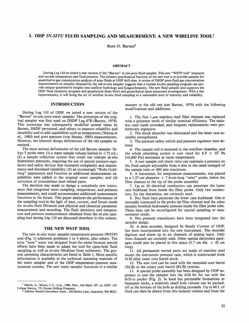
3. ODP IN-SITU FLUID SAMPLING AND MEASUREMENTS A NEW WIRELINE TOOL 1 Ross O. Barnes 2 ABSTRACT During Leg 110 we tested a new version of the "Barnes" in situ pore-fluid sampler. This new "WSTP tool" measures and records temperature and fluid pressure. The primary geochemical function of the new tool is to provide samples for quantitative gas concentration analysis of pore fluids at ODP drill sites. A review of DSDP pore-fluid gas concentration measurements on samples obtained by the old in-situ sampler suggests that a routine in-situ sampling program can pro- vide unique quantitative insights into seafloor hydrology and biogeochemistry. The new fluid sampler also supports the ODP fluid chemistry program and geophysical (heat flow) and geotechnical (pore pressures) investigations. With a few improvements, it will bring the art of wireline in-situ fluid sampling to a reasonable level of maturity and reliability. INTRODUCTION During Leg 110 of ODP, we tested a new version of the "Barnes" in-situ pore-water sampler. The prototype of the orig- inal sampler was first used on DSDP Leg 47B (Barnes, 1979). This prototype was subsequently modified several times by Barnes, DSDP personnel, and others to improve reliability and durability and to add capabilities such as temperature (Yokota et al., 1980) and pore pressure (von Huene, 1985) measurements. However, the inherent design deficiencies of the old sampler re- mained. The most serious deficiencies of the old Barnes sampler-To- kyo T probe were: (1) a water sample volume limited to <75 mL; (2) a sample collection system that could not tolerate in-situ hydrostatic pressures, requiring the use of special pressure regu- lators and safety devices that increased complexity and mainte- nance and decreased reliability; (3) an increasingly "Rube Gold- berg" appearance and function as additional measurement ca- pabilities were added to the original water sampler; and (4) corrosion of nonstainless steel wetted parts. The decision was made to design a completely new instru- ment that integrated water sampling, temperature, and pressure measurements, and could accommodate additional measurement functions in the future. This paper analyzes the performance of the sampling tool in the light of past, current, and future needs for in-situ fluid filtration and physical and chemical parameter measurement and recording. The fluid chemistry and tempera- ture and pressure measurements obtained from the in-situ sam- pling tool during Leg 110 are discussed elsewhere in this volume. THE NEW WSTP TOOL The new in-situ water sampler-temperature-pressure (WSTP) tool (Fig. 1) addresses problems 1 to 4 above, plus others. The term "pore" water was dropped from the name because special efforts have been made to adapt the tool for open-hole fluid sampling as well as in-situ filtration from sediments. The gen- eral operating characteristics are listed in Table 1. More specific information is available in the technical operating manuals of the water sampler and of the ODP temperature-pressure mea- surement systems. The new water sampler functions in a similar Mascle, A., Moore, J. C , et al., 1988. Proc, InitRepts. (Pt. A), ODP, 110: College Station, TX (Ocean Drilling Program). 2 Address: Rosario Geoscience Assoc., 104 Harbor Lane, Anacortes, WA 98221. manner to the old one (see Barnes, 1979) with the following modifications and additions: 1. The fine 1-^rn stainless steel filter element was replaced with a polyester mesh of similar nominal efficiency. The stain- less steel mesh corroded, and frequent replacements were pro- hibitively expensive. 2. The shock absorber was eliminated and the inner case as- sembly strengthened. 3. The pressure safety switch and pressure regulator were de- leted. 4. The sample coil is enclosed in the overflow chamber, and the whole plumbing system is now rated for 6.9 x I0 7 Pa (10,000 Psi) minimum at room temperature. 5. A new sample coil check valve can maintain a pressure on the fluid sample adjustable from 4 atm to the rated strength of the sample tube or 400 atm maximum. 6. A thermistor, for temperature measurements, was placed in a 1.27-cm diameter x 7.6-cm-long "mini" probe, below the filter element at the tip of the probe assembly. 7. Up to 10 electrical conductors can penetrate the lower case bulkhead from inside the filter probe. Only two conduc- tors, for the thermistor, are currently used. 8. Two fluid lines penetrate the lower case bulkhead. One is normally connected to the probe tip filter element and the other samples borehole hydrostatic pressure inside the filter probe tube. These lines can be reconfigured for special sampling or mea- surement needs. 9. Two pressure transducers have been integrated into the sampler design. 10. A data recorder, designed by Randy Current of ODP, has been incorporated into the new instrument. The recorder digitizes and stores up to six channels of analog input. Only three channels are currently used. Other special electronics pack- ages could also be placed in this space (5.7 cm dia. x 42 cm long). 11. All permanent wetted parts are made of stainless steel except the instrument pressure case, which is constructed from 4130 alloy inner core barrel stock. 12. The new tool can be used with the extended core barrel (XCB) or the rotary core barrel (RCB) systems. 13. A special probe assembly has been designed by ODP en- gineers to seal the sampler into the drill bit for use with the drill-in packer (Fig. 2). In hard but permeable formations or basement rocks, a relatively small hole volume can be packed- off at the bottom of the hole as drilling proceeds. Up to 60 L of fluid can then be drawn from this isolated volume and from the 55
Transcript of Ocean Drilling Program Initial Reports Volume 110€¦ · (Pt. A), ODP, 110: College Station, TX...
3 . O D P IN-SITU F L U I D S A M P L I N G A N D M E A S U R E M E N T S A N E W W I R E L I N E T O O L 1
Ross O. Barnes2
ABSTRACT
During Leg 110 we tested a new version of the "Barnes" in situ pore-fluid sampler. This new "WSTP tool" measures and records temperature and fluid pressure. The primary geochemical function of the new tool is to provide samples for quantitative gas concentration analysis of pore fluids at ODP drill sites. A review of DSDP pore-fluid gas concentration measurements on samples obtained by the old in-situ sampler suggests that a routine in-situ sampling program can provide unique quantitative insights into seafloor hydrology and biogeochemistry. The new fluid sampler also supports the ODP fluid chemistry program and geophysical (heat flow) and geotechnical (pore pressures) investigations. With a few improvements, it will bring the art of wireline in-situ fluid sampling to a reasonable level of maturity and reliability.
INTRODUCTION
During Leg 110 of ODP, we tested a new version of the "Barnes" in-situ pore-water sampler. The prototype of the original sampler was first used on DSDP Leg 47B (Barnes, 1979). This prototype was subsequently modified several times by Barnes, DSDP personnel, and others to improve reliability and durability and to add capabilities such as temperature (Yokota et al., 1980) and pore pressure (von Huene, 1985) measurements. However, the inherent design deficiencies of the old sampler remained.
The most serious deficiencies of the old Barnes sampler-Tokyo T probe were: (1) a water sample volume limited to <75 mL; (2) a sample collection system that could not tolerate in-situ hydrostatic pressures, requiring the use of special pressure regulators and safety devices that increased complexity and maintenance and decreased reliability; (3) an increasingly "Rube Goldberg" appearance and function as additional measurement capabilities were added to the original water sampler; and (4) corrosion of nonstainless steel wetted parts.
The decision was made to design a completely new instrument that integrated water sampling, temperature, and pressure measurements, and could accommodate additional measurement functions in the future. This paper analyzes the performance of the sampling tool in the light of past, current, and future needs for in-situ fluid filtration and physical and chemical parameter measurement and recording. The fluid chemistry and temperature and pressure measurements obtained from the in-situ sampling tool during Leg 110 are discussed elsewhere in this volume.
THE NEW WSTP TOOL The new in-situ water sampler-temperature-pressure (WSTP)
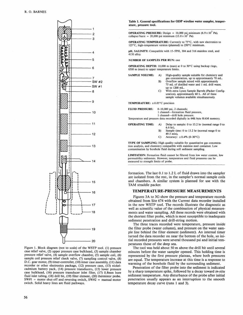
tool (Fig. 1) addresses problems 1 to 4 above, plus others. The term "pore" water was dropped from the name because special efforts have been made to adapt the tool for open-hole fluid sampling as well as in-situ filtration from sediments. The general operating characteristics are listed in Table 1. More specific information is available in the technical operating manuals of the water sampler and of the ODP temperature-pressure measurement systems. The new water sampler functions in a similar
Mascle, A., Moore, J. C , et al., 1988. Proc, InitRepts. (Pt. A), ODP, 110: College Station, TX (Ocean Drilling Program).
2 Address: Rosario Geoscience Assoc., 104 Harbor Lane, Anacortes, WA 98221.
manner to the old one (see Barnes, 1979) with the following modifications and additions:
1. The fine 1-^rn stainless steel filter element was replaced with a polyester mesh of similar nominal efficiency. The stainless steel mesh corroded, and frequent replacements were prohibitively expensive.
2. The shock absorber was eliminated and the inner case assembly strengthened.
3. The pressure safety switch and pressure regulator were deleted.
4. The sample coil is enclosed in the overflow chamber, and the whole plumbing system is now rated for 6.9 x I07 Pa (10,000 Psi) minimum at room temperature.
5. A new sample coil check valve can maintain a pressure on the fluid sample adjustable from 4 atm to the rated strength of the sample tube or 400 atm maximum.
6. A thermistor, for temperature measurements, was placed in a 1.27-cm diameter x 7.6-cm-long "mini" probe, below the filter element at the tip of the probe assembly.
7. Up to 10 electrical conductors can penetrate the lower case bulkhead from inside the filter probe. Only two conductors, for the thermistor, are currently used.
8. Two fluid lines penetrate the lower case bulkhead. One is normally connected to the probe tip filter element and the other samples borehole hydrostatic pressure inside the filter probe tube. These lines can be reconfigured for special sampling or measurement needs.
9. Two pressure transducers have been integrated into the sampler design.
10. A data recorder, designed by Randy Current of ODP, has been incorporated into the new instrument. The recorder digitizes and stores up to six channels of analog input. Only three channels are currently used. Other special electronics packages could also be placed in this space (5.7 cm dia. x 42 cm long).
11. All permanent wetted parts are made of stainless steel except the instrument pressure case, which is constructed from 4130 alloy inner core barrel stock.
12. The new tool can be used with the extended core barrel (XCB) or the rotary core barrel (RCB) systems.
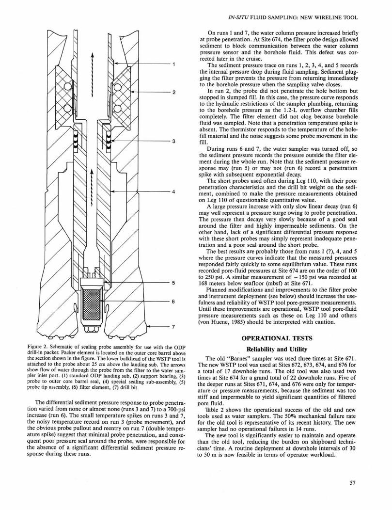
13. A special probe assembly has been designed by ODP engineers to seal the sampler into the drill bit for use with the drill-in packer (Fig. 2). In hard but permeable formations or basement rocks, a relatively small hole volume can be packed-off at the bottom of the hole as drilling proceeds. Up to 60 L of fluid can then be drawn from this isolated volume and from the
55
R. O. BARNES
Figure 1. Block diagram (not to scale) of the WSTP tool. (1) pressure case relief valve, (2) upper pressure case bulkhead, (3) sample chamber pressure relief valve, (4) sample overflow chamber, (5) sample coil, (6) sample coil pressure relief check valve, (7) sampling control valve, (8) D.C. gear motor, (9) timer-controller, (10) inner case assembly, (11) data recorder or other electronics package, (12) pressure case, (13) nickel-cadmium battery pack, (14) pressure transducers, (15) lower pressure case bulkhead, (16) pressure transducer inlet filter, (17) 0.8mm bore fluid inlet tubing, (18) drill bit, (19) filter element, (20) thermistor probe. SW#1 = motor shut-off and reversing switch, SW#2 = manual motor switch. Solid heavy lines are fluid pathways.
Table 1. General specifications for ODP wireline water sampler, temperature, pressure tool.
OPERATING PRESSURE: Design = 10,000 psi minimum (6.9 X I07 Pa), collapse/burst = 20,000 psi minimum (13.8 X I07 Pa).
OPERATING TEMPERATURE: Currently to 75°C, with new electronics to 125°C, high-temperature version (planned) to 250°C minimum.
pH, SALINITY: Compatible with 15-5PH, 304 and 316 stainless steel, and 4130 alloy.
NUMBER OF SAMPLES PER RUN: one
OPERATING DEPTH: 10,000 m (max) at 0 to 30°C using backup rings, 6500 m (max) to upper temperature limits.
SAMPLE VOLUME: A) High-quality sample suitable for chemistry and gas concentration, up to approximately 70 mL.
B) Overflow sample mixed with approximately 75 mL of distilled water and 1 mL drill water, up to 1200 mL.
C) With extra Lynes Sample Barrels (Packer Configuration), approximately 60 L. All of these sample volumes available simultaneously.
TEMPERATURE: ±0.05°C precision
FLUID PRESSURE: 0-10,000 psi, 2 channels; 1 channel—formation fluid pressure, 1 channel—drill hole pressure.
Temperature and pressure data recorded digitally in 64K-byte RAM memory.
OPERATING TIME: A) Delay to sample: 0 to 13.2 hr (normal range 0 to 6.6 hr),
B) Sample time: 0 to 13.2 hr (normal range 0 to 49.5 min),
C) Accuracy: ±0.4% (0-30°C)
TYPE OF SAMPLING: High quality suitable for quantitative gas concentration analysis, and chemistry compatible with stainless steel container. Low contamination by borehole fluid during soft sediment sampling.
LIMITATION: Formation fluid cannot be filtered from low water content, low permeability sediments. However, temperature and fluid pressures can be measured to strength limits of probe.
formation. The last 0.1 to 1.2 L of fluid drawn into the sampler are isolated from the rest, in the sampler's normal sample coils and chambers. A similar system is planned for use with the TAM straddle packer.
TEMPERATURE-PRESSURE MEASUREMENTS
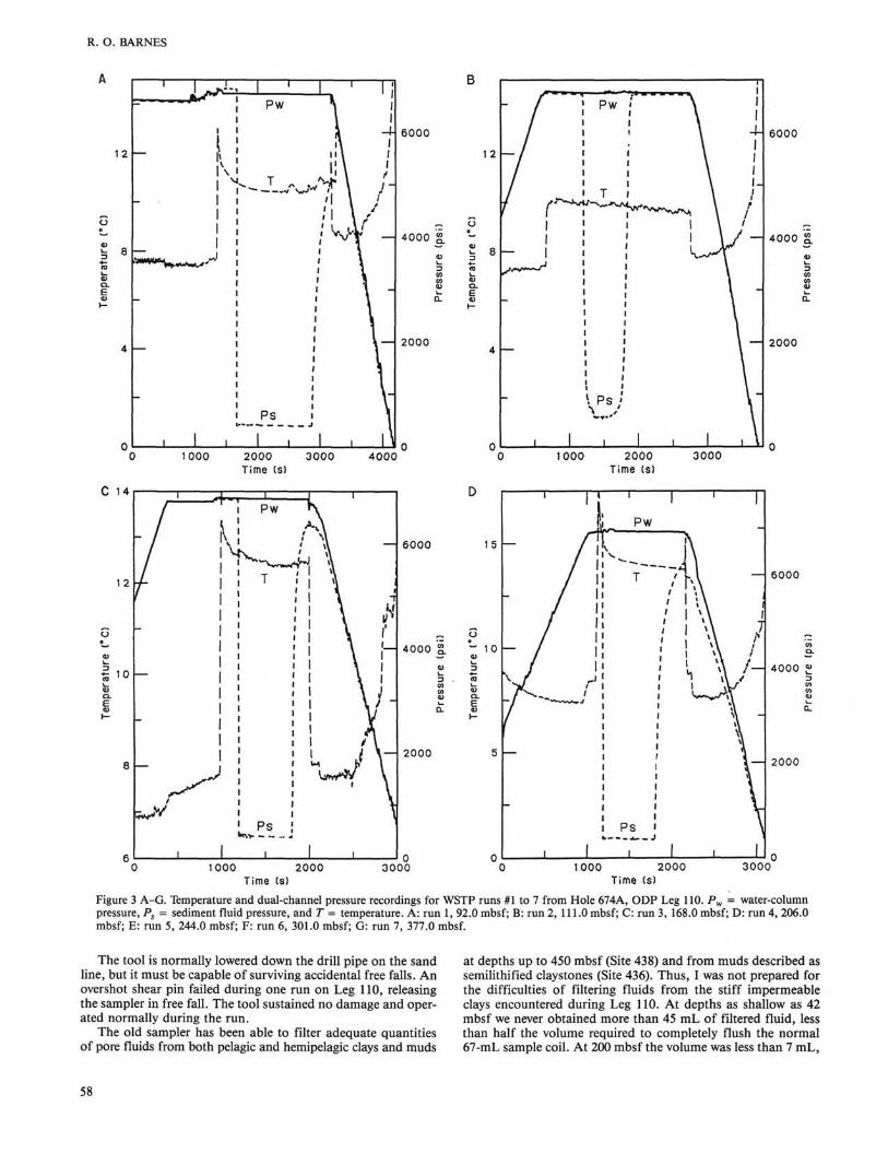
Figures 3A to 3G show the pressure and temperature records obtained from Site 674 with the Current data recorder installed in the new WSTP tool. The records illustrate the diagnostic as well as scientific value of the combination of physical measurements and water sampling. All these records were obtained with the shortest filter probe, which is most susceptible to inadequate sediment penetration and drill-string motion.
The three traces recorded were temperature, pressure inside the filter probe (water column), and pressure on the water sample line behind the filter element (sediment). An internal timer turned the data recorder on near the bottom of the hole, so initial recorded pressures were several thousand psi and initial temperatures those of the deep sea.
The tool was held about 50 m above the drill bit until several minutes before the water sampler opened. This holding time is represented by the first pressure plateau, where both pressures are equal. The temperature increase at this time is a response to warming of the borehole fluid by the surrounding sediment.
Penetration of the filter probe into the sediment is indicated by a sharp temperature spike, followed by a decay toward in-situ sediment temperature. Any disturbance of the probe after initial penetration usually appears as an interruption to the smooth temperature decay curve (runs 1 and 3).
56
IN-SITU FLUID SAMPLING: NEW WIRELINE TOOL
Figure 2. Schematic of sealing probe assembly for use with the ODP drill-in packer. Packer element is located on the outer core barrel above the section shown in the figure. The lower bulkhead of the WSTP tool is attached to the probe about 25 cm above the landing sub. The arrows show flow of water through the probe from the filter to the water sampler inlet port. (1) standard ODP landing sub, (2) support bearing, (3) probe to outer core barrel seal, (4) special sealing sub-assembly, (5) probe tip assembly, (6) filter element, (7) drill bit.
The differential sediment pressure response to probe penetration varied from none or almost none (runs 3 and 7) to a 700-psi increase (run 6). The small temperature spikes on runs 3 and 7, the noisy temperature record on run 3 (probe movement), and the obvious probe pullout and reentry on run 7 (double temperature spike) suggest that minimal probe penetration, and consequent poor pressure seal around the probe, were responsible for the absence of a significant differential sediment pressure response during these runs.
On runs 1 and 7, the water column pressure increased briefly at probe penetration. At Site 674, the filter probe design allowed sediment to block communication between the water column pressure sensor and the borehole fluid. This defect was corrected later in the cruise.
The sediment pressure trace on runs 1, 2, 3, 4, and 5 records the internal pressure drop during fluid sampling. Sediment plugging the filter prevents the pressure from returning immediately to the borehole pressure when the sampling valve closes.
In run 2, the probe did not penetrate the hole bottom but stopped in slumped fill. In this case, the pressure curve responds to the hydraulic restrictions of the sampler plumbing, returning to the borehole pressure as the 1.2-L overflow chamber fills completely. The filter element did not clog because borehole fluid was sampled. Note that a penetration temperature spike is absent. The thermistor responds to the temperature of the hole-fill material and the noise suggests some probe movement in the fill.
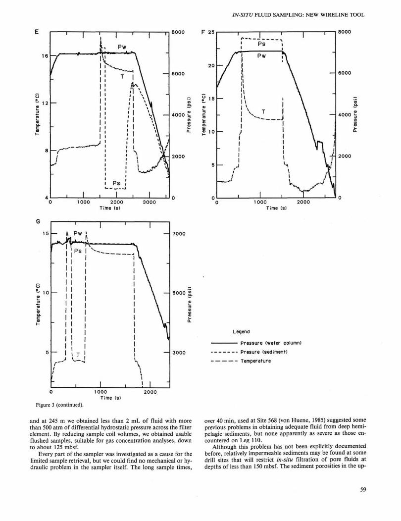
During runs 6 and 7, the water sampler was turned off, so the sediment pressure records the pressure outside the filter element during the whole run. Note that the sediment pressure response may (run 5) or may not (run 6) record a penetration spike with subsequent exponential decay.
The short probes used often during Leg 110, with their poor penetration characteristics and the drill bit weight on the sediment, combined to make the pressure measurements obtained on Leg 110 of questionable quantitative value.
A large pressure increase with only slow linear decay (run 6) may well represent a pressure surge owing to probe penetration. The pressure then decays very slowly because of a good seal around the filter and highly impermeable sediments. On the other hand, lack of a significant differential pressure response with these short probes may simply represent inadequate penetration and a poor seal around the short probe.
The best results are probably those from runs 1 (?), 4, and 5 where the pressure curves indicate that the measured pressures responded fairly quickly to some equilibrium value. These runs recorded pore-fluid pressures at Site 674 are on the order of 100 to 250 psi. A similar measurement of —150 psi was recorded at 168 meters below seafloor (mbsf) at Site 671.
Planned modifications and improvements to the filter probe and instrument deployment (see below) should increase the usefulness and reliability of WSTP tool pore-pressure measurements. Until these improvements are operational, WSTP tool pore-fluid pressure measurements such as these on Leg 110 and others (von Huene, 1985) should be interpreted with caution.
OPERATIONAL TESTS
Reliability and Utility The old "Barnes" sampler was used three times at Site 671.
The new WSTP tool was used at Sites 672, 673, 674, and 676 for a total of 17 downhole runs. The old tool was also used two times at Site 674 for a grand total of 22 downhole runs. Five of the deeper runs at Sites 671, 674, and 676 were only for temperature or pressure measurements, because the sediment was too stiff and impermeable to yield significant quantities of filtered pore fluid.
Table 2 shows the operational success of the old and new tools used as water samplers. The 50% mechanical failure rate for the old tool is representative of its recent history. The new sampler had no operational failures in 14 runs.
The new tool is significantly easier to maintain and operate than the old tool, reducing the burden on shipboard technicians' time. A routine deployment at downhole intervals of 30 to 50 m is now feasible in terms of operator workload.
57
R. O. BARNES
12
a
4
n
1 I .,*•-. 1 ' 1 '
1 • A 1 1 ft : »\
1 i '1 \ i j ; i \
—
1
1 PS i
i . * i r~Ji i
i i
-4-
1 1 t l-
r f i
1 _
V —
\\
6000
4000 S
2000
1000 2000 Time (s)
3000 4000 1000 2000 Time (s)
3000
C 14
1 2
t 10 —
/ i Pw rs
- / &: '"A / ! T
T j ;
— | 1
" ^ i 1 w-v ! i
1 Ps j
1 1 1
1 | H i i t i i l l ~t
1 \ H
V i A.
r \
1 1
8 —
— 6000 15 —
— 4000 10
2000 5 —
6000
— 4000
— 2000
1
\ / - / ^ — - w
1
X 1 1 v
r.1 '
1
1 1 Pw
T 7 i
i
1 1
» i —
» \ '
i i V 1 *v»*s^/*\\
1 \ \
i A
i A
Ps i \
1 , 1
6000
4000 ?
2000
1000 2000 Time (s)
3000 1000 2000 3000 Time (s)
Figure 3 A-G. Temperature and dual-channel pressure recordings for WSTP runs #1 to 7 from Hole 674A, ODP Leg 110. Pw = water-column pressure, Ps = sediment fluid pressure, and T = temperature. A: run 1, 92.0 mbsf; B: run 2, 111.0 mbsf; C: run 3, 168.0 mbsf; D: run 4, 206.0 mbsf; E: run 5, 244.0 mbsf; F: run 6, 301.0 mbsf; G: run 7, 377.0 mbsf.
The tool is normally lowered down the drill pipe on the sand line, but it must be capable of surviving accidental free falls. An overshot shear pin failed during one run on Leg 110, releasing the sampler in free fall. The tool sustained no damage and operated normally during the run.
The old sampler has been able to filter adequate quantities of pore fluids from both pelagic and hemipelagic clays and muds
at depths up to 450 mbsf (Site 438) and from muds described as semilithified claystones (Site 436). Thus, I was not prepared for the difficulties of filtering fluids from the stiff impermeable clays encountered during Leg 110. At depths as shallow as 42 mbsf we never obtained more than 45 mL of filtered fluid, less than half the volume required to completely flush the normal 67-mL sample coil. At 200 mbsf the volume was less than 7 mL,
58
IN-SITU FLUID SAMPLING: NEW WIRELINE TOOL
8000 F 25
— 6000 20 —
15
— 4000 h
« 10
2000
I 1 1
1 — » l
1 \ 1 \
1 \
— J / /
\
l Ps
Pw
T
1
■ 1 1
n
i \ 1 \ I \
-J \ I \ i \
i \ i
i
i
_ i i
i ( J.
¥
i 3
8000
— 6000
4000 i=
2000
0 1000 2000 Time (s)
3000 1000 2000 Time (s)
— 7000
— 5000 £
3000
Legend
— Pressure (water column)
- - Presure (sediment)
Temperature
Figure 3 (continued).
and at 245 m we obtained less than 2 mL of fluid with more than 500 atm of differential hydrostatic pressure across the filter element. By reducing sample coil volumes, we obtained usable flushed samples, suitable for gas concentration analyses, down to about 125 mbsf.
Every part of the sampler was investigated as a cause for the limited sample retrieval, but we could find no mechanical or hydraulic problem in the sampler itself. The long sample times,
over 40 min, used at Site 568 (von Huene, 1985) suggested some previous problems in obtaining adequate fluid from deep hemipelagic sediments, but none apparently as severe as those encountered on Leg 110.
Although this problem has not been explicitly documented before, relatively impermeable sediments may be found at some drill sites that will restrict in-situ filtration of pore fluids at depths of less than 150 mbsf. The sediment porosities in the up-
59
R. O. BARNES
Table 2. Comparison of mechanical reliability of the old and the new Barnes water sampling tools deployed on Leg 110.
cm 0
Number of Sampler tests
Number of mechanical Success
failures rate
Old New
50% 100%
per 200 mbsf at Leg 110 sites (reported elsewhere, this volume) were not substantially lower than those commonly encountered elsewhere. Thus , porosity is not necessarily an indicator of in-situ filtration capacity in fine-grained sediments.
Al though our term "filtration capaci ty" is related to sediment permeability, the two quantities are not directly comparable because in-situ filtration deforms the sediment as fluids are extracted under high differential pressures, creating a cake around the filter that further impedes fluid flow. Nevertheless, we suggest that most of the fine-grained sediments at Leg 110 sites are highly impermeable to bulk flow. Pore-fluid chemistries and heat-flow measurements (reported elsewhere, this volume) suggest that pore fluids are advecting at depth in these sediments. Our experience with in-situ filtration confirms the conclusions of the O D P Leg 110 Scientific Party (1987) that this advection is not bulk flow, but is localized along occasional high-permeability sediment layers, faults, fractures, and dewa-tering veins that provide relatively high permeability paths for fluid migration.
Planned Improvements In soft sediments, a filter probe extending more than 1 m be
yond the end of the drill bit can be used. No difficulty is usually encountered in pushing this probe through hole fill into undisturbed sediments below the previous hole bottom (see Fig. 4). In stiff sediments, the probe length is progressively shortened until the filter element may extend less than 20 cm below the drill bit once the tool is seated. Use of shorter probes prevents a long probe from bending and triggering a pipe trip to remove the water sampler stuck in the drill bit. Frequently, however, the bit cannot be washed completely through the slumped hole fill in stiffer sediments. In this case, the sampler filter is not pushed into undisturbed sediment, and the recovered fluid sample is heavily contaminated by drilling water. The sampling operation is also very susceptible to slight movements of the drill bit off the hole bottom even if the bit is initially washed to the bottom of the hole.
The chances of sample contamination and probe bending can both be reduced if the normal probe, more than 1 m long, is made as strong as possible but is permitted to retract completely inside the drill bit if it encounters excessive penetration resistance.
The ability to decouple the inner core-barrel assembly from the outer core barrel after the filter probe has been pushed into the sediment would also be a useful addition to the WSTP tool operation. Then the 5,000- to 15,000-lb dead weight of the bottom hole assembly could be raised off the hole bottom. This dead weight could affect pore-pressure measurements if the bit remains on hole bottom in a competent formation, as it must using current hardware for WSTP tool operation.
In summary, the following design improvements are being pursued and will be implemented on ODP legs in the near future:
1. Increasing filter element area to maximum practical size, 2. Increasing filter probe diameter and strength to maximum
practical limits,
10
20
30 'M
40
50 I 60
70
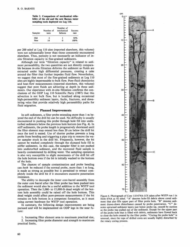
Figure 4. Photograph of Core 110-674A-1IX taken after WSTP run 1 in Hole 674A at 92 mbsf. "A" denotes hole-fill debris above cored sediment that also fills upper part of filter probe hole. " B " denotes sediment drawn-down disturbance caused by probe penetration. " C " denotes upturned sediment layers just below probe tip, caused by suction as the probe was pulled out of the sediment. Except for the upper part of the probe hole that is filled with debris, sediments have flowed back to close the hole created by the filter probe. "Coring the probe hole" is unusual, since the tops of drilled cores are usually highly disturbed by the rotary coring process.
60
IN-SITU FLUID SAMPLING: NEW WIRELINE TOOL
3. Increasing the temperature limit of the water sampler electronics to 125°C, and
4. Developing probe retraction and inner core-barrel decoupling systems for a specialized "instrumentation" inner core-barrel assembly.
DSDP IN-SITU FILTRATION: GEOCHEMICAL RESULTS
Barnes (1979) presented the scientific impetus for developing the old DSDP in-situ water sampler as follows:
"Pore fluid samples are routinely obtained on the D/V Glomar Challenger by pressure filtration of recovered core sections. Chemical specia-tion in the pore fluids can be altered during this procedure by a variety of mechanisms. Temperature and pressure changes during core recovery can alter ion-exchange equilibria between solid and liquid phases. Reduced sediments can be partially oxidized by exposure to oxygenated waters and the atmosphere. Disturbance of the sediment core by the drilling operation and the long residence time of the core in the drill pipe may lead to significant sea water contamination. Escape of C02 from the core material can alter speciation in the carbonate system and lower the alkalinity of the recovered pore water. In situ collected pore water samples can reduce or eliminate these disturbances, thereby providing a valuable check on the accuracy of conventional pore water chemical data.
For accurate dissolved gas concentration measurements, squeezed pore-water samples are not satisfactory because of gas loss and exchange during core recovery and processing (Barnes, 1973). Pore water samples from Glomar Challenger drilling operations that are suitable for dissolved gas analysis would be valuable for several studies. (1) Inert gas concentration profiles are required for investigation of crustal degassing of helium (Barnes and Bieri, 1976); possible paleotemperature data deduced from inert gas ratio measurements (Mazor, 1972); and investigation of the cause of anomalous inert gas concentrations in sedimentary pore waters (Barnes, in preparation). (2) We wish to investigate the interrelationships of various reactions occurring during the biogeochemi-cal cycling of carbon, nitrogen, and sulfur. N2 and N20 are produced during denitrification, and low molecular weight hydrocarbons are produced during anoxic decomposition of organic matter. Does the sequence and relationship of the oxidation-reduction reactions in these systems vary with the rate of reaction? IPOD pore water samples provide a time domain not accessible to surface coring techniques."
Water Chemistry The comparative water chemistry of in-situ filtered and
squeezed core samples has been reported in numerous DSDP Initial Reports (volumes 47B, 49, 54, 56/57, 64, 69, 70, 78A, 84, and possibly others). The in-situ samples have confirmed the general reliability and usefulness of the core squeezing program for routine geochemical interpretations. Chemical species subject to significant concentration shifts resulting from temperature changes, such as K+ and silica, exhibit the expected differences between samples filtered in situ and those squeezed at room temperature in the laboratory (Hesse et al., 1985; Site 676 report, this volume).
The most consistent difference between in-situ and laboratory-filtered samples has been alkalinity (and pH) measurements, where in-situ sample alkalinities are systematically higher (Gieskes et al., 1984), as suggested by Barnes (1979). However, this systematic difference is not always observed in highly reducing sediments where alkalinity increases above 25 mmol/L (Moore and Gieskes, 1980; Hesse et al., 1985).
The in-situ sampler has not been used often enough to detect more subtle effects than those listed above.
Bioactive Gases Because the in-situ water sampler has been the only sampling
tool or method generally available to the ocean drilling programs that can collect pore fluid samples suitable for gas concentration analysis, the limited data available from DSDP have
been of special interest and significance. Analysis of bioactive gases has been limited to N2 and CH4. N2 production during de-nitrification and suboxic diagenesis at DSDP sites generally conforms to the pattern observed in surface ocean sediments. The extended time domain accessible by deep drilling does not change the apparent nitrogen biochemistry from that observed on shorter time scales near the sediment/water interface (Barnes, 1980a; Barnes and Will, 1981).
In more reducing sediments, and especially in sulfate-de-pleted gassy sediments, molecular nitrogen is present at some DSDP sites in amounts far in excess of those observed in similar reducing environments in recent sediments just below the sediment/water interface. The source of this N2 is probably organic nitrogen or NH3 in the sediment, but the production mechanism is not clear, since N2 is not thermodynamically stable in methane-rich, sulfate-depleted fluids. The rate of reproduction is too slow to be observed on the short time scales pertinent to surface sediment geochemistry (Barnes, 1980a; Barnes and Will, 1981).
We also obtained evidence from DSDP in-situ filtered samples that methane consumption and sulfate reduction are not stoichiometrically linked as had been assumed from studies of near surface sediments (Barnes, 1980b).
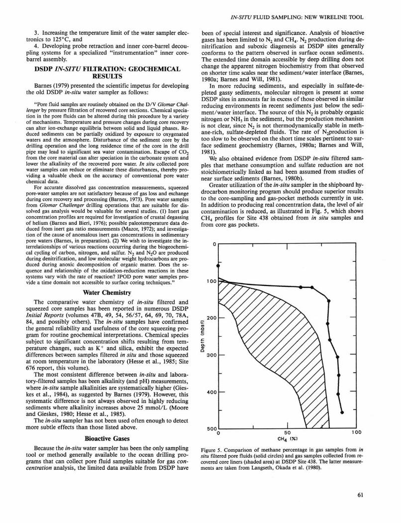
Greater utilization of the in-situ sampler in the shipboard hydrocarbon monitoring program should produce superior results to the core-sampling and gas-pocket methods currently in use. In addition to producing real concentration data, the level of air contamination is reduced, as illustrated in Fig. 5, which shows CH4 profiles for Site 438 obtained from in situ samples and from core gas pockets.
100
200 —
500
300 —
400 —
100
Figure 5. Comparison of methane percentage in gas samples from in situ filtered pore fluids (solid circles) and gas samples collected from recovered core liners (shaded area) at DSDP Site 438. The latter measurements are taken from Langseth, Okada et al. (1980).
61
R. O. BARNES
Inert Gases and Quantitative Hydrology Arguably, the analyses of light inert gases 3He, 4He and Ne
have produced the most significant results from the in-situ sampling program. Analyses accumulated slowly because the old DSDP in-situ sampler did not lend itself to routine use. However, near the end of DSDP, a pattern began to emerge, with four important consequences. First, a thermally and geochemi-cally consistent model for seafloor hydrothermal circulation and rock degassing was developed based on the DSDP and other data (Barnes, Clarke, and Bottomley, 1985). Second, it became clear that helium profiling could provide a valuable and possibly unique tool for studying pore-fluid migration in oceanic sediments. Third, a model was developed to calculate fluid residence times in basement rocks using fluid "helium ages" of near-basement pore waters (Barnes and Clarke, 1987). Finally, the first group of "helium ages" from DSDP sites was used to develop an empirical and intuitive model of fluid circulation in the ocean crust and provided an estimate of the total water flux through the deep-sea floor (Barnes, in press). Selected total hydrothermal chemical fluxes have also been calculated which suggest that ocean crust-to-seawater chemical exchange is dominated by reactions occurring in older seafloor, as opposed to thermal springs on the ridge crests (Barnes, in press).
CONCLUSIONS When the planned improvements to the Leg 110 version of
the WSTP tool have been completed, the tool will have reached a level of design maturity and operational reliability that can support a more routine program of downhole water sampling and measurement than has been possible before. Furthermore, new measurement functions, such as specific ion electrodes or different configurations of the pressure measurement system, can be added without major redesign efforts.
Need for A P C Water Sampler The constraints of downhole time requirements for a wireline
sampling tool generally limit the WSTP to sampling intervals of 30 to 50 m in the upper parts of holes even with the most sympathetic chief scientists. A higher sampling density is necessary to adequately profile pore fluid solutes and gases. An in-situ sampler incorporated into the catcher shoe of the advanced piston corer (APC) would facilitate a higher sampling density (10-20 m) in the upper piston cored sections of ODP drill sites. The feasibility of such a sampler is currently under investigation. The wireline WSTP tool would then be used below the piston cored section and in open holes in hard sediments and basement rocks.
Core Gas Analysis All methods of collecting gas samples from recovered cores
that have been tried during DSDP and ODP to date, suffer from some combination of the following problems:
1. In situ absolute gas concentrations, required for quantitative gas geochemistry, cannot be provided (all methods of sampling core gas pockets, the current shipboard procedure for gas analysis from core samples, and the method of Wakita et al., 1986);
2. The level of atmospheric contamination or gas loss is excessive (all procedures listed in (1), plus Clarke et al., 1973); and
3. The procedure is too involved for routine use (Clarke et al., 1973).
As Leg 110 graphically illustrates, any in-situ filtration program will be limited to the upper portions of most ODP drill sites, yet geochemical processes involving gases do not stop at this arbitrary depth. The lack of a core gas sampling procedure suitable for quantitative analysis is a serious deficiency in the ODP geochemistry program and should receive attention.
Forward Look An in-situ sampling program's primary goal should be the
recovery of fluid samples suitable for quantitative gas concentration analyses, because such samples cannot be obtained by other means (a core gas sampling method, if one is developed, would remain of second tier importance to be used when in-situ filtration is not possible). Quantitative analysis of both bioac-tive and inert gases at ODP drill sites should provide a unique and important data base for studies of seafloor hydrology and biogeochemistry.
The development of a successful APC in-situ water sampler will materially assist the ODP fluid chemistry program by returning greater numbers of in-situ filtered samples. These APC samples will also be less subject to contamination from drilling fluid than samples squeezed from cores or filtered in situ with the wireline WSTP tool, because the core catcher of the APC extends almost 10 m below the drill bit. Thus, more subtle comparisons between in-situ filtered and core-squeezed fluid chemistry can be made. Lower levels of drilling fluid contamination may also provide higher precision analyses desired for certain studies, such as detection of relict paleoceanographic salinity variations in marine sediments (McDuff, 1985).
ACKNOWLEDGMENTS This research was supported by NSF grant OCE85-12087 to the Uni
versity of Washington, including a subcontract to Rosario Geoscience Associates. Reviews by R. E. McDuff and E. Taylor improved the substance and presentation of this report.
REFERENCES Barnes, R. O., 1973. An in situ interstitial water sampler for use in un-
consolidated sediments. Deep-Sea Res., 20:1125-1128. Barnes, R. O., 1979. Operation of the IPOD in situ pore water sampler.
In Sibuet, J.-C, Ryan, W. B. E, et al., Init. Repts. DSDP, 47, Pt. 2: Washington (U.S. Govt. Printing Office), 19-22.
Barnes, R. O., 1980a. Nitrogen diagenesis in marine sediments: evidence for sub-oxic and anoxic conversion of organic N to N2 gas. In Trudinger, P. A., Walter, M. R., and Ralph, B. J. (Eds.), Biogeochemistry of Ancient and Modern Environments: Canberra (Aust. Acad. Sci.), 299-309.
Barnes, R. O., 1980b. Anoxic methane consumption in marine sediments: some problems with current geochemical models (abs.). Geol. Soc. Am., Abstracts with Programs, 1980 Annual Meetings, 93:383.
Barnes, R. O., in press. Fluid and chemical fluxes between sea water and basement rocks during "active" and "passive" hydrothermal circulation in the oceanic crust. Earth Planet. Sci. Lett.
Barnes, R. O., and Bieri, R. H., 1976. Helium flux through marine sediments of the northeast Pacific Ocean. Earth Planet. Sci. Lett., 28: 331-336.
Barnes, R. O., and Clarke, W. B., in press. Fluid kinematics, fluid residence times and rock degassing in oceanic crust, determined from noble gas contents of DSDP pore waters. J. Geophys. Res.
Barnes, R. O., Clarke, WB. , and Bottomley, R. J., 1985. Thermal and helium mass balance during hydrothermal convection in oceanic crust. Eos, 66:401. (Abstract)
Barnes, R. O., and Will. B. R., 1981. Physical and diagenetic controls on the concentrations of dissolved Ar, N2 and CH4 in pore fluids from DSDP legs 47 to 57. Eos, 62:900. (Abstract)
Clarke, W. B., Horowitz, R. M., and Broecker, W S., 1973. Interstitial water studies, leg 15—inert gases. In Heezen, B. C , MacGregor, I. D., et al., Init. Repts. DSDP, 20: Washington (U.S. Govt. Printing Office), 777-781.
Gieskes, J. M., Elderfield, H., Lawrence, J. R., and LaKind, J., 1984. Interstitial water studies, leg 78A. In Biju-Duval, B., Moore, J. C , et al., Init. Repts. DSDP, ISA: Washington (U.S. Govt. Printing Office), 377-384.
Hesse, R., Lebel, J., and Gieskes, J. M., 1985. Interstitial water chemistry of gas-hydrate-bearing sections on the Middle America Trench slope, Deep Sea Drilling Project leg 84. In von Huene, R., Aubouin, J., et al., Init. Repts. DSDP, 84: Washington (U.S. Govt. Printing Office), 727-737.
62
IN-SITU FLUID SAMPLING: NEW WIRELINE TOOL
Langseth, M., Okada, H., von Huene, R., Nasu, N., et al., 1980. Init. Repts. DSDP, 56/57, part 1: Washington (U.S. Govt. Printing Office).
Mazor, E., 1972. Paleotemperatures and other hydrological parameters deduced from noble gases dissolved in groundwaters; Jordan Rift Valley, Israel. Geochim. Cosmochim. Acta, 36:1321-1336.
McDuff, R. E., 1985. The chemistry of interstitial waters, Deep Sea Drilling Project leg 86. In Heath, G. R., Burckle, L. H., et al., Init. Repts. DSDP, 86: Washington (U.S. Govt. Printing Office), 675-687.
Moore, G. W , and Gieskes, J. M., 1980. Interaction between sediment and interstitial water near the Japan Trench, leg 57, Deep Sea Drilling Project. In Langseth, M., Okada, H., von Huene, R., Nasu, N., et al., Init. Repts. DSDP, 56/57, part 2: Washington (U.S. Govt. Printing Office), 1269-1275.
ODP Leg 110, Scientific Party, 1987. Expulsion of fluids, irom depth along a subduction-zone decollement horizon. Nature, 326:785-788.
von Huene, R., 1985. Direct measurement of pore fluid pressure, leg 84, Guatemala and Costa Rica. In von Huene, R., Aubouin, J., et al., Init. Repts. DSDP, 84: Washington (U.S. Govt. Printing Office), 767-772.
Wakita, H., Sano, Y., Fujii, N., and Takeuchi, A., 1986. 3He/4He ratios of pore gases in deep-sea sediments, legs 89 and 90. In Kennett, J. P., von der Borch, C. C , et al., Init. Repts. DSDP, 90 (Pt. 2): Washington (U.S. Govt. Printing Office), 1261-1263.
Yokota, T , Kinoshita, H., and Uyeda, S., 1980. New DSDP (Deep Sea Drilling Project) downhole temperature probe utilizing IC RAM (memory) elements. Bull. Earthquake Res. Inst. Univ. Tokyo, 55: 75-88.
Ms 110A-104
63