Obstacle alert and collision avoidance system development ...
91
BACHELOR’S THESIS Degree in Aerospace Engineering Obstacle alert and collision avoidance system development for UAVs with Pixhawk flight controller Crist´ obal Cuevas Garc´ ıa June 2018 Supervisors Xin Chen David Morante Gonz´ alez This work is licensed under Creative Commons Attribution – Non Commercial – Non Derivatives brought to you by CORE View metadata, citation and similar papers at core.ac.uk provided by Universidad Carlos III de Madrid e-Archivo
Transcript of Obstacle alert and collision avoidance system development ...
BACHELOR’S THESIS
Degree in Aerospace Engineering
Obstacle alert and collision avoidancesystem development for UAVs
with Pixhawk flight controller
Cristobal Cuevas Garcıa
June 2018
SupervisorsXin Chen
David Morante Gonzalez
This work is licensed under Creative Commons Attribution – NonCommercial – Non Derivatives
brought to you by COREView metadata, citation and similar papers at core.ac.uk
provided by Universidad Carlos III de Madrid e-Archivo

Abstract
In recent years, the unmanned aerial vehicles sector has been characterized by itssharp growth, spreading its line of applications and becoming one of the cuttingedge technologies in the world. However, this exponential advancement would havebeen even more extreme but for the restrictive existing legislation that limits itsoperations.
That constraints imposed to drone operations are not legislated in vain. Specially inpopulated areas, flying drones is a dangerous service that entails risks for the safetyof the population. Useless have been the attempts of many major online sellingcompanies to make use of unmanned aerial vehicles serving as dealers of parcels.Further technology needs still to be implemented, for guarantying standards levelsof safety in urban zones.
This thesis aims to contribute to this required development of drone technologyby proposing a preliminary collision avoidance system for unmanned aerial vehi-cles. The project involves assembling a flight-capable quadcopter from scratch andimplementing the collision avoidance as an additional subsystem. To that end, aset of ultrasonic range finders are located around the quadcopter. Their acquiredraw data is processed in an auxiliary arduino microcontroller board that send tra-jectory corrections to the flight controller of the quadcopter based on the distanceinformation.
As a result, a concept proof of an autonomous collision avoidance system is integratedinto an unmanned aerial vehicle system. Results are obtained and consecutivelyanalyzed based on ground and flight tests. For that purpose, the flight capabilitiesof the built quadcopter are proved, and aftewards, the collision avoidance is tested.Overall, the collision avoidance system effectiveness was achieved. The collisionavoidance work principle consisted on warding off from obstacles when detected.Major faced problems are related to stability recover after the collision is avoided.That problem was solved by proving different flight modes, but that issue needsfuture work to make the collision avoidance more reliable.
Keywords: collision avoidance, ultrasonic range finder, Arduino board,Pixhawk flight controller, obstacle detection, environment monitoring,overwritten pitch/roll angles
iii

Acknowledgements
Firstly, I would like to dedicate this thesis to my family, for their endless supportand dedication, always providing me with the best education and resources at theirdisposal.
Also, thanks to Xin Chen for your great support and measureless patience throughthe development of this thesis. A big thank you also to David Morante, for providingme with the best technical support and advice always I needed it.
I would also like to dedicate this thesis to my cousin Damian, for providing with aplace to test my quadcopter.
I want to thank all my classmates and friends who encouraged me to keep workingon this thesis.
Finally, but not less important, I want to thank Mercedes, for being the best travelpartner one could ever imagine.
v

Contents
Abstract iii
Acknowledgements v
List of Figures x
List of Tables xii
List of abbreviations 1 xiv
List of abbreviations 2 xv
1 Introduction 11.1 First approach to Collision Avoidance and in UAS . . . . . . . . . . . 11.2 Socioeconomic Impact . . . . . . . . . . . . . . . . . . . . . . . . . . 41.3 Legal Framework . . . . . . . . . . . . . . . . . . . . . . . . . . . . . 41.4 Project Objectives . . . . . . . . . . . . . . . . . . . . . . . . . . . . 61.5 Budget . . . . . . . . . . . . . . . . . . . . . . . . . . . . . . . . . . . 7
1.5.1 Software Cost . . . . . . . . . . . . . . . . . . . . . . . . . . . 71.5.2 Hardware Cost . . . . . . . . . . . . . . . . . . . . . . . . . . 71.5.3 Personnel expenses . . . . . . . . . . . . . . . . . . . . . . . . 7
1.6 Outline of the document . . . . . . . . . . . . . . . . . . . . . . . . . 8
2 State of The Art 92.1 Unmanned aerial vehicles . . . . . . . . . . . . . . . . . . . . . . . . . 9
2.1.1 MAV classification . . . . . . . . . . . . . . . . . . . . . . . . 92.2 Distance Sensing . . . . . . . . . . . . . . . . . . . . . . . . . . . . . 11
2.2.1 Light Detection and Ranging (LiDAR) . . . . . . . . . . . . . 112.2.2 Sound Navigation and Ranging (SoNAR) . . . . . . . . . . . . 122.2.3 Radio Detection and Ranging (RaDAR) . . . . . . . . . . . . 12
2.3 Collision Avoidance in UAVs . . . . . . . . . . . . . . . . . . . . . . . 13
3 UAV components 153.1 Hardware Components . . . . . . . . . . . . . . . . . . . . . . . . . . 15
3.1.1 Frame . . . . . . . . . . . . . . . . . . . . . . . . . . . . . . . 153.1.2 Rotors . . . . . . . . . . . . . . . . . . . . . . . . . . . . . . . 173.1.3 Propellers . . . . . . . . . . . . . . . . . . . . . . . . . . . . . 183.1.4 Electronic Speed Controllers (ESC) . . . . . . . . . . . . . . . 193.1.5 Power . . . . . . . . . . . . . . . . . . . . . . . . . . . . . . . 193.1.6 Flight Controller . . . . . . . . . . . . . . . . . . . . . . . . . 203.1.7 Arduino Mega 2560 . . . . . . . . . . . . . . . . . . . . . . . . 223.1.8 Telemetry . . . . . . . . . . . . . . . . . . . . . . . . . . . . . 233.1.9 Radio transmitter and receiver . . . . . . . . . . . . . . . . . . 233.1.10 Ultrasonic range finder . . . . . . . . . . . . . . . . . . . . . . 24
vii
3.2 Software elements . . . . . . . . . . . . . . . . . . . . . . . . . . . . . 243.2.1 Ubuntu 16.04 . . . . . . . . . . . . . . . . . . . . . . . . . . . 243.2.2 APM Planner . . . . . . . . . . . . . . . . . . . . . . . . . . . 253.2.3 Arduino IDE . . . . . . . . . . . . . . . . . . . . . . . . . . . 27
3.3 Communications . . . . . . . . . . . . . . . . . . . . . . . . . . . . . 273.3.1 RC control . . . . . . . . . . . . . . . . . . . . . . . . . . . . . 273.3.2 MAVLink . . . . . . . . . . . . . . . . . . . . . . . . . . . . . 28
4 Collision Avoidance System Design 314.1 Collision Avoidance System Requirements . . . . . . . . . . . . . . . 314.2 Collision Avoidance System Stages . . . . . . . . . . . . . . . . . . . 34
4.2.1 Minimum altitude activation level . . . . . . . . . . . . . . . . 344.2.2 Horizontal environment sensing . . . . . . . . . . . . . . . . . 354.2.3 Obstacle detection . . . . . . . . . . . . . . . . . . . . . . . . 354.2.4 Collision avoidance Maneuver . . . . . . . . . . . . . . . . . . 36
4.3 Collision Avoidance Algorithm flow diagram . . . . . . . . . . . . . . 39
5 Collision Avoidance System Implementation 405.1 Quadcopter assembly, wiring and calibration-making the drone flight
capable . . . . . . . . . . . . . . . . . . . . . . . . . . . . . . . . . . . 405.2 CAS Hardware Integration . . . . . . . . . . . . . . . . . . . . . . . . 45
5.2.1 Arduino Mega 2560-Pixhawk flight controller . . . . . . . . . . 465.2.2 Arduino Mega 2560-Ultrasonic range finder HC-SR04 . . . . . 475.2.3 F450 kit-Ultrasonic range finder HC-SR04 . . . . . . . . . . . 485.2.4 F450 kit-Arduino Mega 2560 . . . . . . . . . . . . . . . . . . . 49
5.3 CAS software integration . . . . . . . . . . . . . . . . . . . . . . . . . 515.3.1 Distance data acquisition and processing . . . . . . . . . . . . 515.3.2 Arduino board as an UAV system . . . . . . . . . . . . . . . . 525.3.3 Obstacle alert and collision avoidance . . . . . . . . . . . . . 54
6 Testing and Results 566.1 Flight capabilities tests and results . . . . . . . . . . . . . . . . . . . 56
6.1.1 Stabilize flight mode . . . . . . . . . . . . . . . . . . . . . . . 566.1.2 Altitude hold mode . . . . . . . . . . . . . . . . . . . . . . . . 57
6.2 Component testing and results . . . . . . . . . . . . . . . . . . . . . . 586.2.1 HC-SR04 Ultrasonic range finders . . . . . . . . . . . . . . . . 586.2.2 Arduino Mega 2560 . . . . . . . . . . . . . . . . . . . . . . . . 60
6.3 MAVLink communication testing and results . . . . . . . . . . . . . . 606.4 Obstacle collision avoidance ground tests . . . . . . . . . . . . . . . . 60
6.4.1 Arming and disarming test . . . . . . . . . . . . . . . . . . . . 606.4.2 Collision avoidance system ground test . . . . . . . . . . . . . 61
6.5 Obstacle collision avoidance flight tests . . . . . . . . . . . . . . . . . 666.5.1 Stabilize flight mode test . . . . . . . . . . . . . . . . . . . . . 666.5.2 Altitude hold flight mode test . . . . . . . . . . . . . . . . . . 67
viii
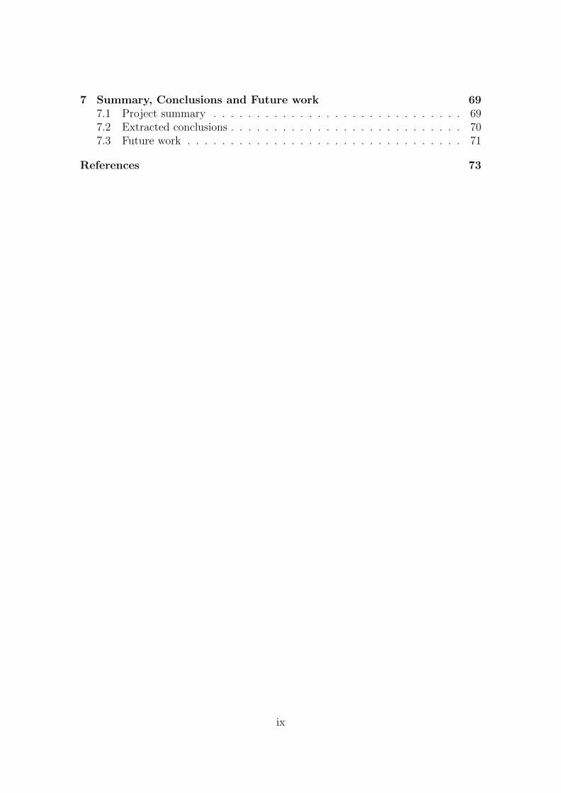
7 Summary, Conclusions and Future work 697.1 Project summary . . . . . . . . . . . . . . . . . . . . . . . . . . . . . 697.2 Extracted conclusions . . . . . . . . . . . . . . . . . . . . . . . . . . . 707.3 Future work . . . . . . . . . . . . . . . . . . . . . . . . . . . . . . . . 71
References 73
ix
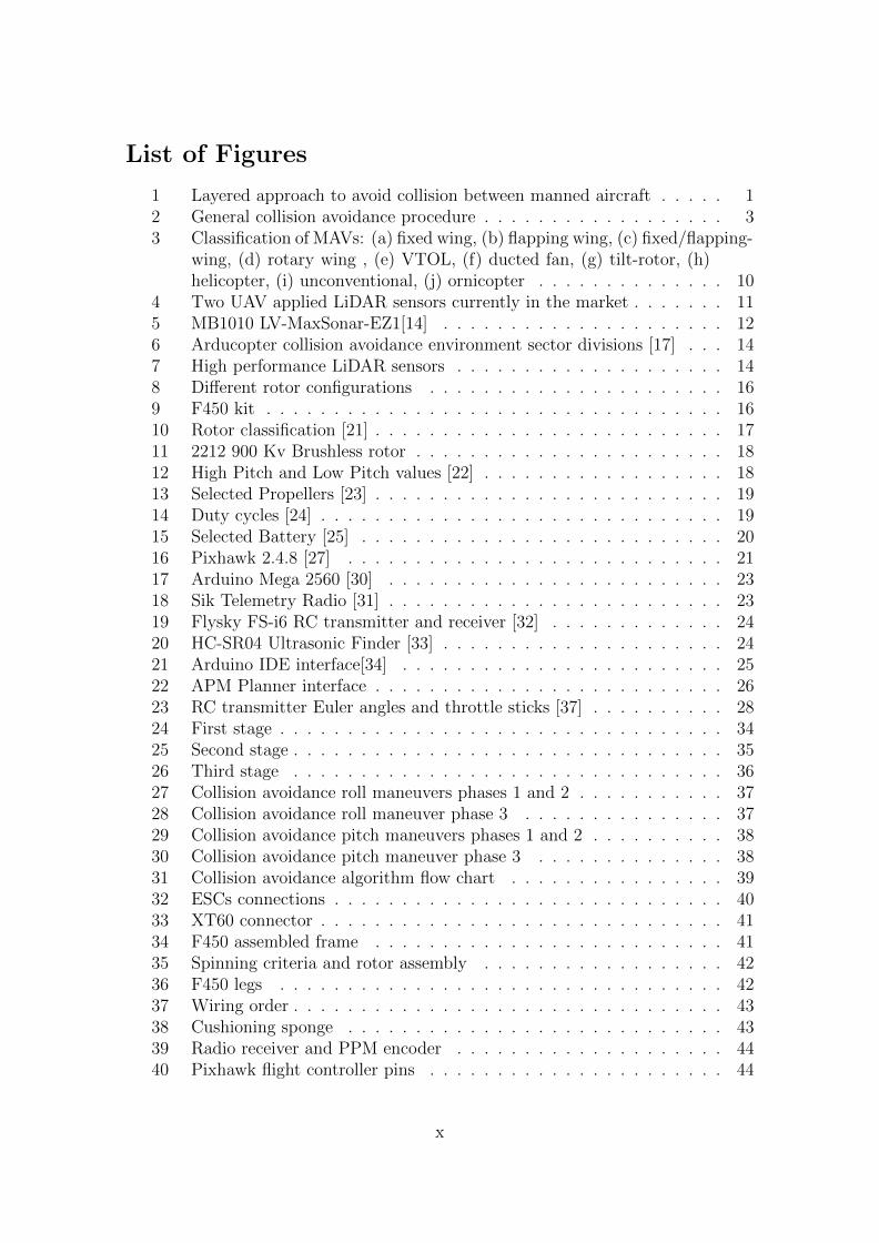
List of Figures
1 Layered approach to avoid collision between manned aircraft . . . . . 12 General collision avoidance procedure . . . . . . . . . . . . . . . . . . 33 Classification of MAVs: (a) fixed wing, (b) flapping wing, (c) fixed/flapping-
wing, (d) rotary wing , (e) VTOL, (f) ducted fan, (g) tilt-rotor, (h)helicopter, (i) unconventional, (j) ornicopter . . . . . . . . . . . . . . 10
4 Two UAV applied LiDAR sensors currently in the market . . . . . . . 115 MB1010 LV-MaxSonar-EZ1[14] . . . . . . . . . . . . . . . . . . . . . 126 Arducopter collision avoidance environment sector divisions [17] . . . 147 High performance LiDAR sensors . . . . . . . . . . . . . . . . . . . . 148 Different rotor configurations . . . . . . . . . . . . . . . . . . . . . . 169 F450 kit . . . . . . . . . . . . . . . . . . . . . . . . . . . . . . . . . . 1610 Rotor classification [21] . . . . . . . . . . . . . . . . . . . . . . . . . . 1711 2212 900 Kv Brushless rotor . . . . . . . . . . . . . . . . . . . . . . . 1812 High Pitch and Low Pitch values [22] . . . . . . . . . . . . . . . . . . 1813 Selected Propellers [23] . . . . . . . . . . . . . . . . . . . . . . . . . . 1914 Duty cycles [24] . . . . . . . . . . . . . . . . . . . . . . . . . . . . . . 1915 Selected Battery [25] . . . . . . . . . . . . . . . . . . . . . . . . . . . 2016 Pixhawk 2.4.8 [27] . . . . . . . . . . . . . . . . . . . . . . . . . . . . 2117 Arduino Mega 2560 [30] . . . . . . . . . . . . . . . . . . . . . . . . . 2318 Sik Telemetry Radio [31] . . . . . . . . . . . . . . . . . . . . . . . . . 2319 Flysky FS-i6 RC transmitter and receiver [32] . . . . . . . . . . . . . 2420 HC-SR04 Ultrasonic Finder [33] . . . . . . . . . . . . . . . . . . . . . 2421 Arduino IDE interface[34] . . . . . . . . . . . . . . . . . . . . . . . . 2522 APM Planner interface . . . . . . . . . . . . . . . . . . . . . . . . . . 2623 RC transmitter Euler angles and throttle sticks [37] . . . . . . . . . . 2824 First stage . . . . . . . . . . . . . . . . . . . . . . . . . . . . . . . . . 3425 Second stage . . . . . . . . . . . . . . . . . . . . . . . . . . . . . . . . 3526 Third stage . . . . . . . . . . . . . . . . . . . . . . . . . . . . . . . . 3627 Collision avoidance roll maneuvers phases 1 and 2 . . . . . . . . . . . 3728 Collision avoidance roll maneuver phase 3 . . . . . . . . . . . . . . . 3729 Collision avoidance pitch maneuvers phases 1 and 2 . . . . . . . . . . 3830 Collision avoidance pitch maneuver phase 3 . . . . . . . . . . . . . . 3831 Collision avoidance algorithm flow chart . . . . . . . . . . . . . . . . 3932 ESCs connections . . . . . . . . . . . . . . . . . . . . . . . . . . . . . 4033 XT60 connector . . . . . . . . . . . . . . . . . . . . . . . . . . . . . . 4134 F450 assembled frame . . . . . . . . . . . . . . . . . . . . . . . . . . 4135 Spinning criteria and rotor assembly . . . . . . . . . . . . . . . . . . 4236 F450 legs . . . . . . . . . . . . . . . . . . . . . . . . . . . . . . . . . 4237 Wiring order . . . . . . . . . . . . . . . . . . . . . . . . . . . . . . . . 4338 Cushioning sponge . . . . . . . . . . . . . . . . . . . . . . . . . . . . 4339 Radio receiver and PPM encoder . . . . . . . . . . . . . . . . . . . . 4440 Pixhawk flight controller pins . . . . . . . . . . . . . . . . . . . . . . 44
x

41 GCS calibration display . . . . . . . . . . . . . . . . . . . . . . . . . 4542 Arduino Mega 2560-Pixhawk flight controller pin connection . . . . . 4643 Arduino Mega 2560-HC-SR04 range finder pin connection . . . . . . . 4844 Lateral and bottom ultrasonic range finders . . . . . . . . . . . . . . 4945 Arduino Mega 2560 assembled to the bottom of the power distribution
board . . . . . . . . . . . . . . . . . . . . . . . . . . . . . . . . . . . 5046 Collision avoidance hardware layout . . . . . . . . . . . . . . . . . . . 5047 Final prototype . . . . . . . . . . . . . . . . . . . . . . . . . . . . . . 5148 UAS linked to the GCS . . . . . . . . . . . . . . . . . . . . . . . . . . 5349 Collision avoidance system communication lost alert . . . . . . . . . . 5350 Ultrasonic range finders locations . . . . . . . . . . . . . . . . . . . . 5451 Video footage frame of stabilize mode test . . . . . . . . . . . . . . . 5652 PID recommended parameters [41] . . . . . . . . . . . . . . . . . . . 5753 Prompted distances (cm) from the 5 ultrasonic range finders . . . . . 5954 Arming and disarming test . . . . . . . . . . . . . . . . . . . . . . . . 6155 Prompted PWM commands . . . . . . . . . . . . . . . . . . . . . . . 6256 Drone response to pitch PWM outputs based on distances to front
sensor 1 . . . . . . . . . . . . . . . . . . . . . . . . . . . . . . . . . . 6357 Drone response to pitch PWM outputs based on distances to back
sensor 3 . . . . . . . . . . . . . . . . . . . . . . . . . . . . . . . . . . 6458 Drone response to roll PWM outputs based on distances to right
sensor 2 . . . . . . . . . . . . . . . . . . . . . . . . . . . . . . . . . . 6559 Drone response to roll PWM outputs based on distances to left sensor 4 6660 Collision avoidance flight test video footage frame . . . . . . . . . . . 68
xi
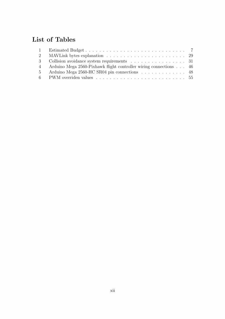
List of Tables
1 Estimated Budget . . . . . . . . . . . . . . . . . . . . . . . . . . . . . 72 MAVLink bytes explanation . . . . . . . . . . . . . . . . . . . . . . . 293 Collision avoidance system requirements . . . . . . . . . . . . . . . . 314 Arduino Mega 2560-Pixhawk flight controller wiring connections . . . 465 Arduino Mega 2560-HC SR04 pin connections . . . . . . . . . . . . . 486 PWM overriden values . . . . . . . . . . . . . . . . . . . . . . . . . . 55
xii

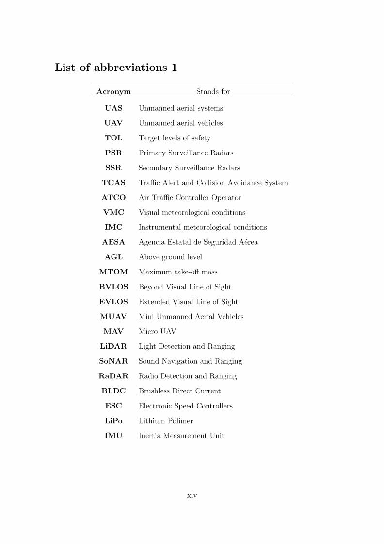
List of abbreviations 1
Acronym Stands for
UAS Unmanned aerial systems
UAV Unmanned aerial vehicles
TOL Target levels of safety
PSR Primary Surveillance Radars
SSR Secondary Surveillance Radars
TCAS Traffic Alert and Collision Avoidance System
ATCO Air Traffic Controller Operator
VMC Visual meteorological conditions
IMC Instrumental meteorological conditions
AESA Agencia Estatal de Seguridad Aerea
AGL Above ground level
MTOM Maximum take-off mass
BVLOS Beyond Visual Line of Sight
EVLOS Extended Visual Line of Sight
MUAV Mini Unmanned Aerial Vehicles
MAV Micro UAV
LiDAR Light Detection and Ranging
SoNAR Sound Navigation and Ranging
RaDAR Radio Detection and Ranging
BLDC Brushless Direct Current
ESC Electronic Speed Controllers
LiPo Lithium Polimer
IMU Inertia Measurement Unit
xiv
List of abbreviations 2
Acronym Stands for
GCS Ground Control Station
RC Radio Control
PPM Pulse Position Modulation
MAVLink Micro Air Vehicle Link
CAS Collision Avoidance System
ESC Electronic speed controllers
xv


Bachelor’s Thesis
1 Introduction
The purpose of this section lies on approaching the reader to collision avoidanceadaption to UAS and its socioeconomic impact. Then, a legal framework aboutUAVs in Spain is given; and finally, and more directly related with this project, theproject objectives, the budget and the outline of the document are presented.
1.1 First approach to Collision Avoidance and in UAS
Collision avoidance development in UAS is coming out as an essential solution for theintroduction of UAS traffic in the civil airspace. Technologies in this field are beingdeveloped worldwidely. Prerequisites for its implementation are highly intricate andvary depending on the target airspace. The collision hazards when mixing withmanned air vehicles are way too diverse, and makes this development a laborioustask.
The airspace has an international set of standards and regulations to guarantee andensure that the risk of collision for manned aircraft is consistent with an acceptableTarget Level of Safety (TLOS).[1].
For a collision to occur, failures must happen in multiple layers, as depicted in Figure1.
Figure 1: Layered approach to avoid collision between manned aircraft[1]
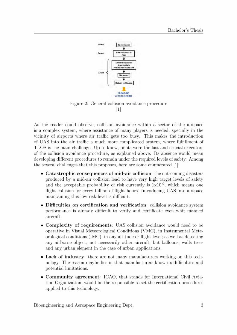
Layer 1 is not specifically focused on avoiding collision, while layers two to five followthe same procedure to prevent collision between two or several aircraft/airborneelements. That procedure is shown in Figure 2 where the following elements aredelineated [1]:
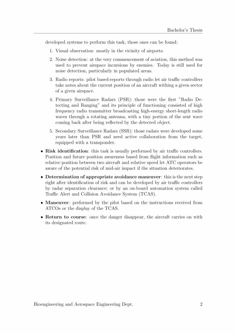
• Surveillance: surveillance consist of determining the position (lateral or ver-tical) of any vehicle or object within any sector of the airspace [2]. Among the
Bioengineering and Aerospace Engineering Dept. 1
Bachelor’s Thesis
developed systems to perform this task, those ones can be found:
1. Visual observation: mostly in the vicinity of airports.
2. Noise detection: at the very commencement of aviation, this method wasused to prevent airspace incursions by enemies. Today is still used fornoise detection, particularly in populated areas.
3. Radio reports: pilot based-reports through radio let air traffic controllerstake notes about the current position of an aircraft withing a given sectorof a given airspace.
4. Primary Surveillance Radars (PSR): those were the first ”Radio De-tecting and Ranging” and its principle of functioning consisted of highfrequency radio transmitter broadcasting high-energy short-length radiowaves through a rotating antenna, with a tiny portion of the sent wavecoming back after being reflected by the detected object.
5. Secondary Surveillance Radars (SSR): those radars were developed someyears later than PSR and need active collaboration from the target,equipped with a transponder.
• Risk identification: this task is usually performed by air traffic controllers.Position and future position awareness based from flight information such asrelative position between two aircraft and relative speed let ATC operators beaware of the potential risk of mid-air impact if the situation deteriorates.
• Determination of appropriate avoidance maneuver: this is the next stepright after identification of risk and can be developed by air traffic controllersby radar separation clearance; or by an on-board automation system calledTraffic Alert and Collision Avoidance System (TCAS).
• Maneuver: performed by the pilot based on the instructions received fromATCOs or the display of the TCAS.
• Return to course: once the danger disappear, the aircraft carries on withits designated route.
Bioengineering and Aerospace Engineering Dept. 2
Bachelor’s Thesis
Figure 2: General collision avoidance procedure[1]
As the reader could observe, collision avoidance within a sector of the airspaceis a complex system, where assistance of many players is needed, specially in thevicinity of airports where air traffic gets too busy. This makes the introductionof UAS into the air traffic a much more complicated system, where fulfillment ofTLOS is the main challenge. Up to know, pilots were the last and crucial executorsof the collision avoidance procedure, as explained above. Its absence would meandeveloping different procedures to remain under the required levels of safety. Amongthe several challenges that this proposes, here are some enumerated [1]:
• Catastrophic consequences of mid-air collision: the out-coming disastersproduced by a mid-air collision lead to have very high target levels of safetyand the acceptable probability of risk currently is 1x10⁻⁹, which means oneflight collision for every billion of flight hours. Introducing UAS into airspacemaintaining this low risk level is difficult.
• Difficulties on certification and verification: collision avoidance systemperformance is already difficult to verify and certificate even whit mannedaircraft.
• Complexity of requirements: UAS collision avoidance would need to beoperative in Visual Meteorological Conditions (VMC), in Instrumental Mete-orological conditions (IMC), in any altitude or flight level; as well as detectingany airborne object, not necessarily other aircraft, but balloons, walls treesand any urban element in the case of urban applications.
• Lack of industry: there are not many manufacturers working on this tech-nology. The reason maybe lies in that manufacturers know its difficulties andpotential limitations.
• Community agreement: ICAO, that stands for International Civil Avia-tion Organization, would be the responsible to set the certification proceduresapplied to this technology.
Bioengineering and Aerospace Engineering Dept. 3
Bachelor’s Thesis
1.2 Socioeconomic Impact
During the last 10 years, technology development has allowed clients to get frontline products at reasonable prices. Originally, drones were a technology that wasonly under the scope of military institutions due to its elevated cost and its leadingtechnology. Nevertheless, economies of scale has lead to the possibility of purchasingthose flight devices for prices ranging between $50 and $100 [3].
Companies such as Amazon or Google have already in mind further projects relatedto drones. They are just waiting for a suitable development of the legal framework.Amazon has promised to its clients a future system of parcel (under 51 lb) deliverybased on the use of UAS [4]. Google, in contrast, is developing an aerial systemof drones with the scope of environmental conservation and medicine deliver tounreachable and remote zones. Drones are considered as environmentally-friendlydevices, since they do not require fuel to operate, and the majority of them areelectrically powered.
The commercial benefits from drones is irrefutable. A recent investigation [3] hasestimated that from 2015 to 2015, UAV implementation into national USA airspacewould lead to $82.1 billion in terms of economic growth and job creation, with thetotality of 100,000 new jobs.
The main UAV markets are oriented to infrastructures, agriculture, transport, se-curity, media, insurance, telecommunications and mining. Agriculture is one of theUAV sectors with more future, due to the UAV abilities to cover large areas, servingby feeding and hydrating plants while monitoring spread of disease and their health.
Jobs created within the mentioned range of 10 years would be primarily in themanufacturing sector. States would undoubtedly get benefits from tax windfallsfrom the increased economic activity. Commercial drones would also allow industriessave expenses in terms of inventory, transportation and distribution.
1.3 Legal Framework
Up to this section, this thesis has refereed to the legality of drones based on inter-national laws and international civil aviation institutions. However, national civilaviation institutions have not yet been able to harmonize a common legal frame-work valid for all countries. Therefore, since this project has been developed in anUniversity located in Spain; the national legal situation concerning UAVs will bepresented in this unit. All the information here presented has been retrieved fromReal Decreto 1036/2017 [5]. This is the current law that applies for the civil use ofremotely piloted aircraft in Spain. In other words, it is the regulation for the use ofdrones within the boundaries of the country.
Bioengineering and Aerospace Engineering Dept. 4
Bachelor’s Thesis
• License requisites for piloting drones
License is only required for individuals who are going to perform professionaltasks by direct manipulation of drones. In those cases, an issued title bya certificated academy needs to provided, in which the person demonstratesa practical and theoretical knowledge about piloting of drones as well as amedical certificate.
• Requirements to be fulfilled to operate professionally with drones
1. Registration in AESA as a UAV operator.
2. Holding a civil responsibility insurance.
3. Holding UAV pilot title.
4. Holding medical certificate into effect.
• Requirements to be fulfilled to operate recreationally with drones
1. Flying within a distance under 8 kilometers to any aerodrome or airport.
2. Flying outside of a controlled airspace.
3. Flying under 120 meters of height (AGL)
4. Flying daily and under proper meteorological conditions. In case of pi-loting an UAV under 2 Kg, night flights are allowed but never over 50meters (AGL).
5. Flying always within the visual observation range of the pilot.
6. UAVs under 250 g can overfly cities and crowds but never over 20 meters.
7. Even though it is not mandatory, holding a civil responsibility insuranceis strongly recommended.
• Any UAV will need to hold a data plate with the following informa-tion
1. Manufacturer
2. Type
3. Model
4. Serial number
5. Name and contact details of the operator
• Requirements to operate UAVs professionally in urban zones andover crowds
1. MTOM under 10 Kg
2. Operation performed within the visual range of the pilot.
Bioengineering and Aerospace Engineering Dept. 5
Bachelor’s Thesis
3. The flight zone must be ribbed by the competent authorities. If thatis not the case, a minimum horizontal distance of 50 meters must bepreserved from buildings and people.
4. The UAV must have a system of impact energy absorption (parachute,airbag...).
5. AESA must authorize the operation.
• Requirements to operate night UAV flights
1. AESA must authorize the flight based on a specific safety study.
• Requirements to operate UAV in controlled airspace
1. The UAV must be equipped with a transponder in mode S.
2. The pilot must hold a radiophonist license.
3. The pilot must accredit to know the language of communication betweenthe ATCO and the UAV.
4. AESA must authorize the flight.
• Requirements to operate UAV with MTOW over 2 Kg over thevisual range of the pilot (BVLOS)
1. The UAV must be equipped with systems able to detect and avoid otherusers of the airspace.
2. The UAV must be equipped with a vision device oriented facing forward.
• Requirements to operate UAV within EVLOS
1. The flights will be permitted under the presence of intermediate observers.
2. The intermediate observers will remain in constant radio communicationwith the pilot and will accredit the theoretical knowledge of a remotepilot.
1.4 Project Objectives
As stated in the Abstract, this project aims to assemble and testing a flight-capablequadcopter from scratch and implementing a collision avoidance subsystem into it.Inside this scope, the following objectives can be stated:
• Building from scratch a flight capable drone to be used as a prototype in whichimplementing afterwards a Collision Avoidance System.
• Proving the flight capabilities of the prototype based on flight testing.
• Designing an Obstacle Collision System.
Bioengineering and Aerospace Engineering Dept. 6
Bachelor’s Thesis
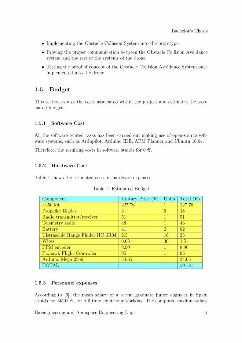
• Implementing the Obstacle Collision System into the prototype.
• Proving the proper communication between the Obstacle Collision Avoidancesystem and the rest of the systems of the drone.
• Testing the proof of concept of the Obstacle Collision Avoidance System onceimplemented into the drone.
1.5 Budget
This sections states the costs associated within the project and estimates the asso-ciated budget.
1.5.1 Software Cost
All the software related tasks has been carried out making use of open-source soft-ware systems, such as Ardupilot, Arduino IDE, APM Planner and Ubuntu 16.04.
Therefore, the resulting costs in software stands for 0 e.
1.5.2 Hardware Cost
Table 1 shows the estimated costs in hardware expenses.
Table 1: Estimated Budget
Component Unitary Price (€) Units Total (€)F450 kit 227.76 1 227.76Propeller Blades 3 6 18Radio transmitter/receiver 51 1 51Telemetry radio 48 1 48Battery 41 2 82Ulstrasonic Range Finder HC SR04 2.5 10 25Wires 0.05 30 1.5PPM encoder 8.90 1 8.90Pixhawk Flight Controller 95 1 95Arduino Mega 2560 34.65 1 34.65TOTAL 591.81
1.5.3 Personnel expenses
According to [6], the mean salary of a recent graduate junior engineer in Spainstands for 24501 €, for full time eight-hour workday. The computed medium salary
Bioengineering and Aerospace Engineering Dept. 7
Bachelor’s Thesis
per hour is computed as 13.61 €.
The estimated time dedicated to this project is over 650 hours. Therefore, it wouldcorrespond to a personnel expenses of 8846.50 € if a recent graduate engineer sim-ulated this project.
1.6 Outline of the document
This document is structured in several sections.
• Section 2 introduces to the reader the current state of art about collisionavoidance and environment sensing applied to UAVs.
• In section 3, all the quadcopter hardware components and software elementsare presented, together with the communications among the UAV subsystems.
• In section 4, the collision avoidance system design is covered, defining thedifferent collision avoidance stages, the sense algorithm and the system re-quirements.
• Section 5 covers the quadcopter building process, together with the obstaclecollision avoidance system hardware and software implementation into it.
• In section 6, the ground and flight tests are detailed, analyzing and exposingthe obtained results.
• Finally, in section 7 the outcoming conclusions and future work purposes arepresented.
Bioengineering and Aerospace Engineering Dept. 8
Bachelor’s Thesis
2 State of The Art
Unmanned aerial Vehicles (UAVs) has a huge range of applications. Companies ofthis sector have concentrated their efforts on developing UAVs capable of successfullyperform their demanded tasks; as well as a software to establish communicationamong the hardware components and to provide the users with a reliable interfaceto communicate and operate the UAVs.
2.1 Unmanned aerial vehicles
Unmanned Aerial Vehicles (UAVs) stand for aircraft without an human pilot aboard.UAVs are a component of an UAS, that include the UAV, a ground-based controllerand the system of communication between those two [7]. In this project, a Micro AirVehicle (MAV) is utilized, a F450 quadcopter under 2 Kg. MAV stands for dronesunder 2 Kg and over 50 g of weight and ranging between 15 cm and 100 cm of size[8].
2.1.1 MAV classification
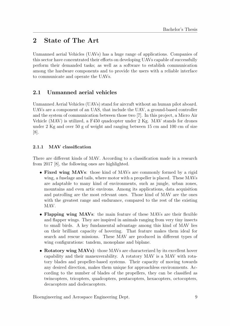
There are different kinds of MAV. According to a classification made in a researchfrom 2017 [8], the following ones are highlighted.
• Fixed wing MAVs: those kind of MAVs are commonly formed by a rigidwing, a fuselage and tails, where motor with a propeller is placed. These MAVsare adaptable to many kind of environments, such as jungle, urban zones,mountains and even artic environs. Among its applications, data acquisitionand patrolling are the most relevant ones. Those kind of MAV are the oneswith the greatest range and endurance, compared to the rest of the existingMAV.
• Flapping wing MAVs: the main feature of these MAVs are their flexibleand flapper wings. They are inspired in animals ranging from very tiny insectsto small birds. A key fundamental advantage among this kind of MAV lieson their brilliant capacity of hovering. That feature makes them ideal forsearch and rescue missions. These MAV are produced in different types ofwing configurations: tandem, monoplane and biplane.
• Rotatory wing MAVs): those MAVs are characterized by its excellent hovercapability and their maneuverability. A rotatory MAV is a MAV with rota-tory blades and propeller-based systems. Their capacity of moving towardsany desired direction, makes them unique for approachless environments. Ac-cording to the number of blades of the propellers, they can be classified astwincopters, tricopters, quadcopters, pentacopters, hexacopters, octocopters,decacopters and dodecacopters.
Bioengineering and Aerospace Engineering Dept. 9
Bachelor’s Thesis
Figure 3: Classification of MAVs: (a) fixed wing, (b) flapping wing, (c)fixed/flapping-wing, (d) rotary wing , (e) VTOL, (f) ducted fan, (g) tilt-rotor, (h)helicopter, (i) unconventional, (j) ornicopter[8]
Bioengineering and Aerospace Engineering Dept. 10
Bachelor’s Thesis
2.2 Distance Sensing
Distance sensing is a leading technology that has application in many sectors of theengineering. Applied to UAVs, current state of art shows that their main utilizationapplies for environment mapping, terrain shape following, altitude measuring andcollision avoidance [9].
2.2.1 Light Detection and Ranging (LiDAR)
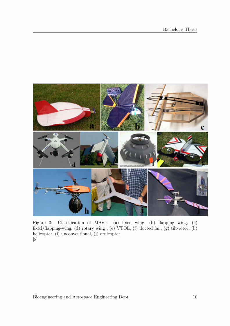
Light Detection and Ranging (LiDAR) sensor is a technology of precise measure-ment based on the time elapsed between transmitting a pulsed optical laser signaland receiving its reflection. Thus, there are two signals types in this kind of mea-surement method: reference signal from the transmitter and reflected received signalfrom target. This process is called correlation, where the distance to the target iscalculated based on the time delay and using the speed of light constant [10] .
LiDARs work at different electromagnetic wavelengths depending of its line of ap-plications. For instance, meteorology LiDARs work always on infrared (1500 nm to2000 nm) and on ultraviolet (250 nm) wavelengths.
The work principle of LiDARs is based on this equation:
L = ct
2(1)
Where L is the distance, t is the time elapsed between sending and receiving thepulse and c is the light velocity constant.
There currently exist in the market LiDAR sensors for drones with high outstandingperformances.
(a) Velodyne HDL-32E [11] (b) LeddarOne[12]
Figure 4: Two UAV applied LiDAR sensors currently in the market
Bioengineering and Aerospace Engineering Dept. 11
Bachelor’s Thesis
2.2.2 Sound Navigation and Ranging (SoNAR)
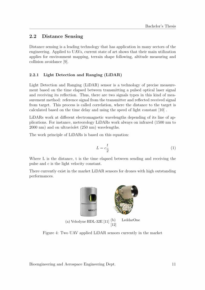
SoNAR is based on emitting and receiving sound waves signals. By measuring thetime delay between the sent pulse and received pulse it is possible to compute thedistance from the target [13].
Among its applications,a significant one is measuring the depth of water surfaceswhen installed on ships. SoNAR sensor are much more useful on water environmentsrather than outdoor environments, since the propagation of sound through water isfaster. It is likewise employed in submarines to detect vessels and in ships in orderto locate fish targets. On medicine field, SoNARs sensors are usually employed fordesease detection and monitoring unborn children.
Distance measurement is computed similarly as in the case of LiDARs. The onlyelement that changes is the velocity, that in this case is the one of the sound, whichchanges depending on the medium of propagation.
A high-performance SoNAR employed in the UAV sector is illustrated in figure 5
Figure 5: MB1010 LV-MaxSonar-EZ1[14]
2.2.3 Radio Detection and Ranging (RaDAR)
Radar is an alternative technology that makes use of radio waves to measure dis-tances. The principle of functioning is based on the reflected emitted signals.RaDAR sensors are compounded of an antenna, a transmitter and a receiver. Thetransmitter sends the radio-wave that propagates at the speed of light c. Whenreaching the objective, the wave hits the target and comes back reflected to thereceiver. The reflected signal is detected and analyzed as radio echo by the antenna,and the signal is amplified by the receiver.
Civilian and military applications are within the line of applications of RaDARs [15].They are usually employed in aircraft to measure distances from ground controlstations and other objects within the airspace. Additionally, they are utilized ingeology for identification of areas for mineral prospection; in agriculture for cropmonitoring; in cartography for altimetric elevations; in hydrology for soil humiditydetection; or in oceanography for ships detection and illegal fishing monitoring [16].
Bioengineering and Aerospace Engineering Dept. 12
Bachelor’s Thesis
2.3 Collision Avoidance in UAVs
As mentioned in Section 1.1, the most employed collision avoidance system in currentaviation is TCAS. And according to current legislation, drones aiming to cover routeswithin a controlled airspace should have it equipped.
However, industry is developing drones for recreative use with collision avoidancetechnology incorporated. The benefits are patent. For the pilot, sometimes it is everyeasy to get carried away in the middle of an operation. If the pilot get distractedfor a while, the drone could easily fly into an object.
Drones are also employed in many crowded areas and events since they can capturefilms with unreachable angles for the traditional cam operators. Unfortunately, therehave been some accidents and safety of the people is a must that should be preservedwithout exceptions.
In recent years, some models with collision avoidance equipment have been releasedto the market. They are all equipped with one to six sensors located in the fourssides, top and bottom. The most popular ones are Kespry 2, DJI Spark and DJIPhantom 4 Pro. The most prominent one is Kespry 2, which has 5 directions ofobstacle sensing and 4 directions of obstacle avoidance. Apart from that, someintelligent flight modes are provided, as well as a super smooth stability and a top4k camera.
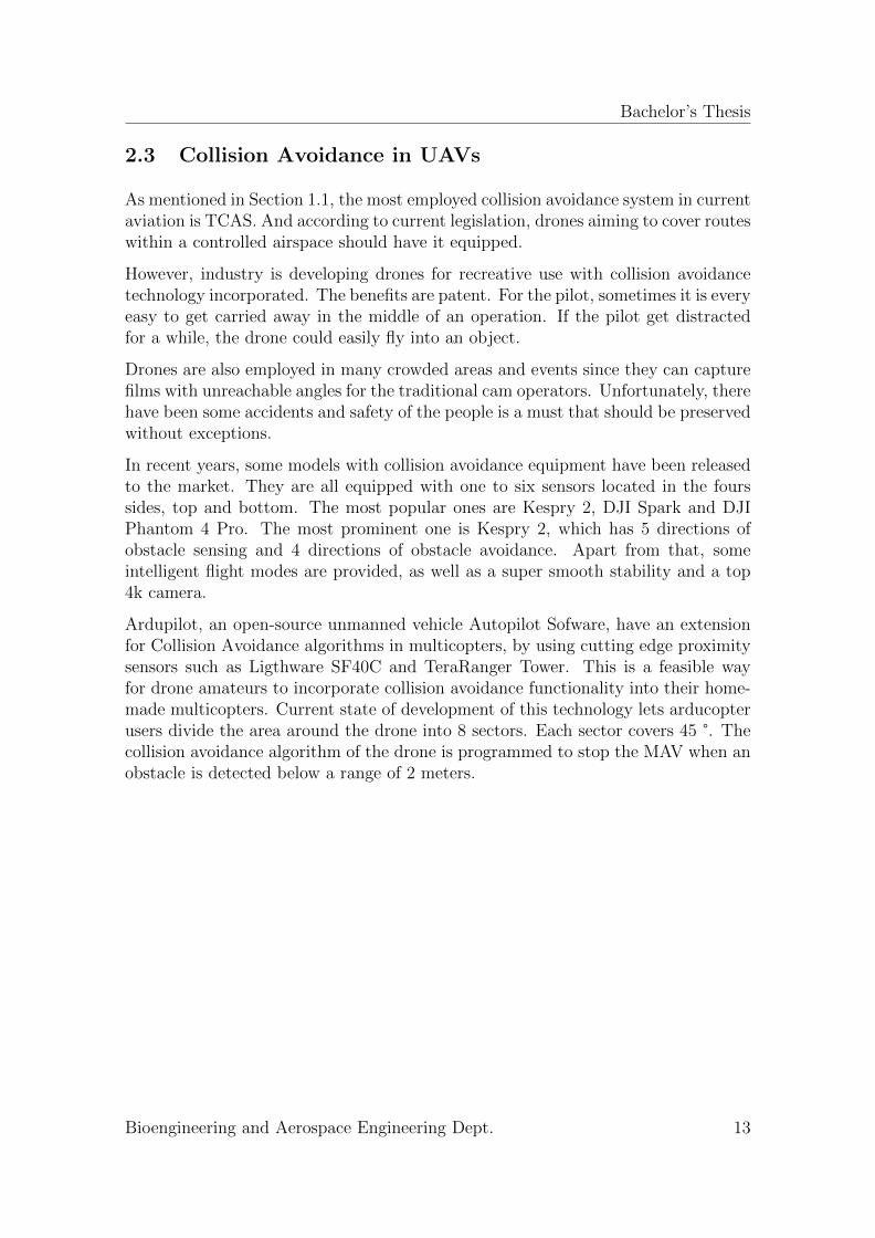
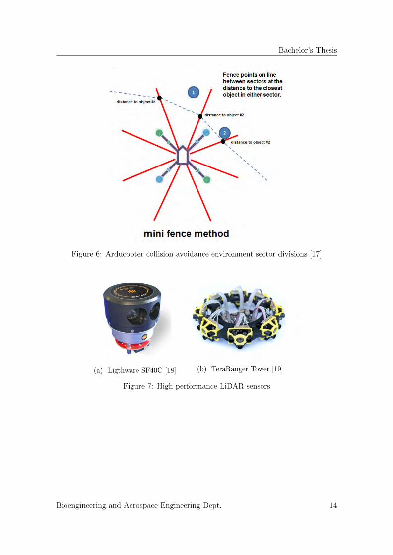
Ardupilot, an open-source unmanned vehicle Autopilot Sofware, have an extensionfor Collision Avoidance algorithms in multicopters, by using cutting edge proximitysensors such as Ligthware SF40C and TeraRanger Tower. This is a feasible wayfor drone amateurs to incorporate collision avoidance functionality into their home-made multicopters. Current state of development of this technology lets arducopterusers divide the area around the drone into 8 sectors. Each sector covers 45 °. Thecollision avoidance algorithm of the drone is programmed to stop the MAV when anobstacle is detected below a range of 2 meters.
Bioengineering and Aerospace Engineering Dept. 13
Bachelor’s Thesis
Figure 6: Arducopter collision avoidance environment sector divisions [17]
(a) Ligthware SF40C [18] (b) TeraRanger Tower [19]
Figure 7: High performance LiDAR sensors
Bioengineering and Aerospace Engineering Dept. 14
Bachelor’s Thesis
3 UAV components
In this section, the UAV hardware components, the software elements and the com-munications among all the subsystems of the quadcopter will be presented.
3.1 Hardware Components
As previously explained, in order to implement the collision avoidance system intothe drone, it was first needed to assembly and testing a capable flight drone. Theselected drone was a quadcopter F450. It is important to remark that most of thecomponents used within this project belongs to the Bioengineering and AerospaceEngineering Department of the University Carlos III of Madrid. Only the Pixhawkflight controller and the PPM encoder were bought to complete the scope of thisproject. Hence, a quadcopter was selected due to the fact that all the needed com-ponents to mount it were already present. Moreover, a quadcopter is one of the mostproper MAV types to prove and implement such a complex system. Quadrotors pro-vide the users with the possibility of hovering flights, making the collision avoidancetesting more feasible and simple, taking into the account the null experience withinpiloting those vehicles of the writer of this thesis before immersing in this project.
Following sections introduce to the reader the hardware components employed inthe execution of this project.
3.1.1 Frame
Frame is the element of MAV in charge on linking all the subsystems and providingthe MAV with a physical integrity . In the current market, there exist several kinds ofmultirotor frames, from bicopter (two propelled MAV) to octacopter (eight propelledMAV). The frame is basically the MAV structure that holds all the componentswithin the MAV. It is compounded by arms, landing gears, rotor mounts and centralplates. Central plates usually have a dual function. It is the assembly node wherelanding gears and arms connect, and also include the power distribution wiringfor powering the remaining components. The F450 kit frame employed within thisproject has two central plates. The upper plate works as linking node and thebottom plate works as PDB and as linking node as well.
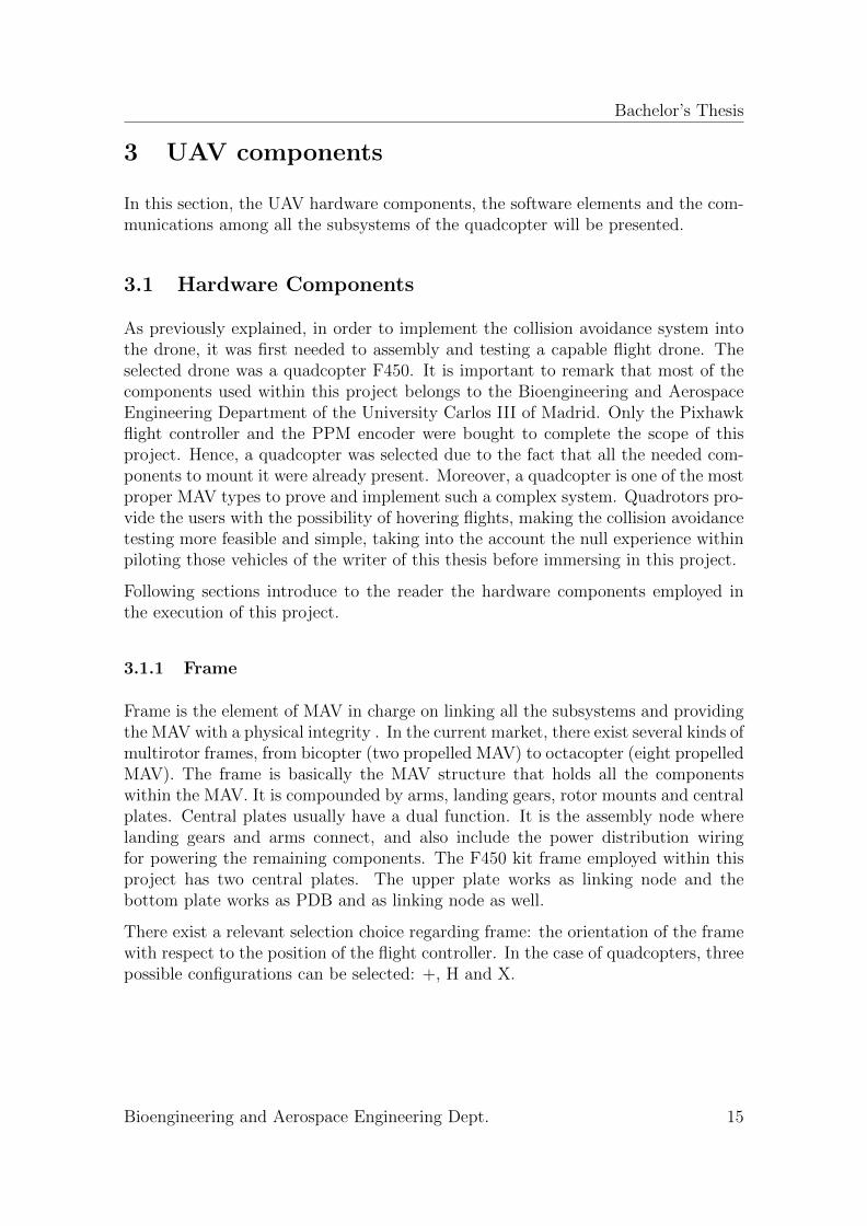
There exist a relevant selection choice regarding frame: the orientation of the framewith respect to the position of the flight controller. In the case of quadcopters, threepossible configurations can be selected: +, H and X.
Bioengineering and Aerospace Engineering Dept. 15
Bachelor’s Thesis
(a) H configuration [20] (b) X Configuration [20] (c) + Configuration [20]
Figure 8: Different rotor configurations
Frame selection must be based on the further applications of the drone. The numberof motors selected must be consistent with the future mission performed by theMAV. Two levers are varied depending on the number of motors: stability andendurance. For missions where endurance is a major concern, it is convenient toused copters with no more than four motors. For missions such as infrastructureinspection or crop monitoring, the stability of the drone is a significant issue that canbe strongly improved by increasing the number of rotors. There exist two differentframe configurations: flat and coaxial. Flat configuration only allows each arm tohave one motor mounted, while coaxial configuration is designed to incorporate twosimilar coaxial motors on each arm.
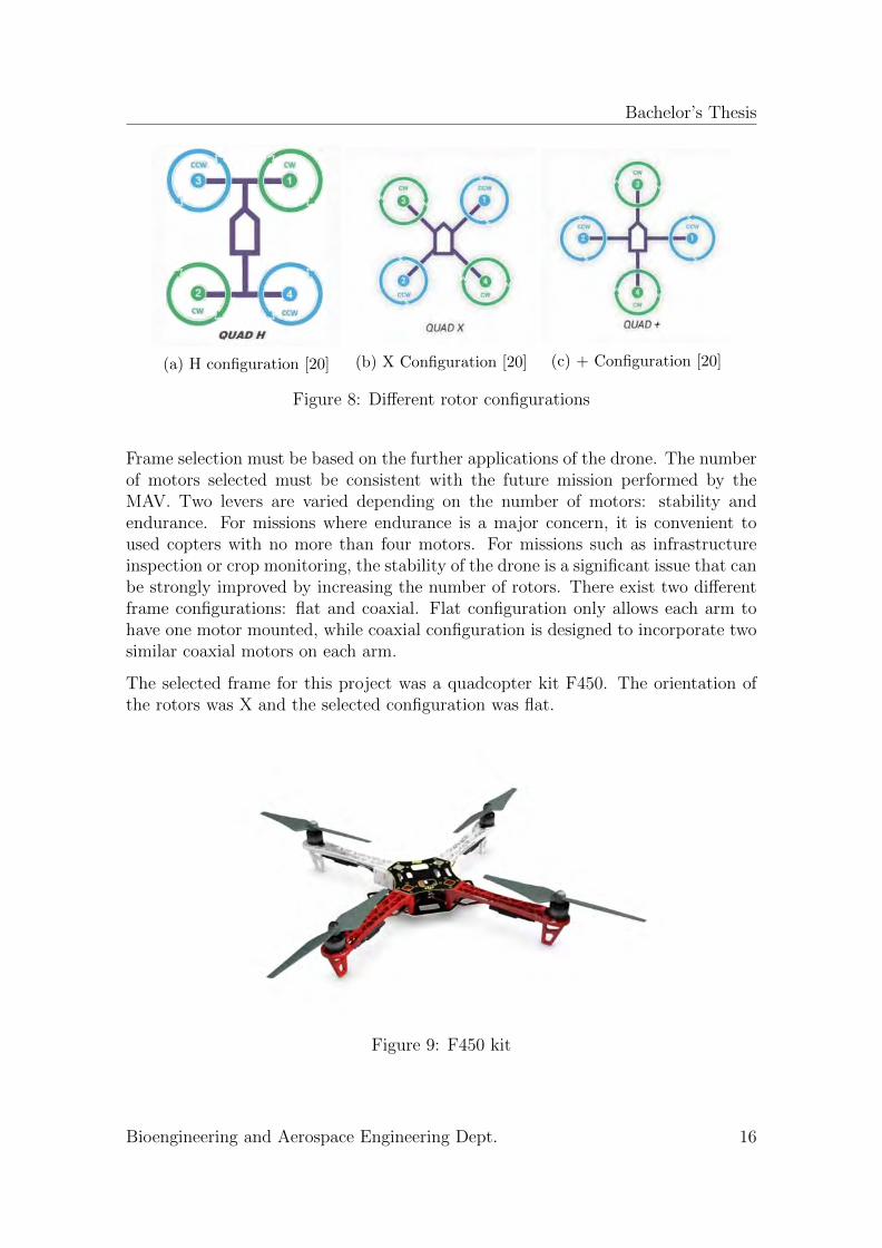
The selected frame for this project was a quadcopter kit F450. The orientation ofthe rotors was X and the selected configuration was flat.
Figure 9: F450 kit
Bioengineering and Aerospace Engineering Dept. 16
Bachelor’s Thesis
3.1.2 Rotors
The aim of rotors is lifting the quadcopter and letting it move within the wholespace. The flight controller adjusts the angular velocities of the motors to move thevehicle towards the desired direction.
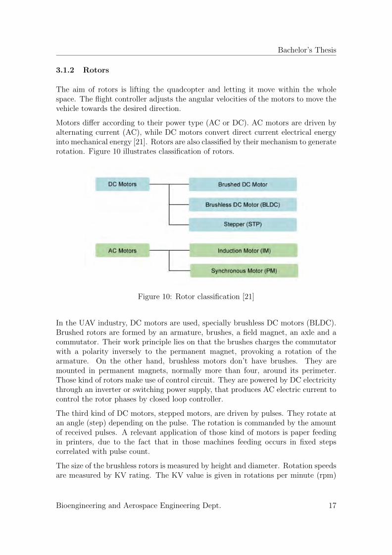
Motors differ according to their power type (AC or DC). AC motors are driven byalternating current (AC), while DC motors convert direct current electrical energyinto mechanical energy [21]. Rotors are also classified by their mechanism to generaterotation. Figure 10 illustrates classification of rotors.
Figure 10: Rotor classification [21]
In the UAV industry, DC motors are used, specially brushless DC motors (BLDC).Brushed rotors are formed by an armature, brushes, a field magnet, an axle and acommutator. Their work principle lies on that the brushes charges the commutatorwith a polarity inversely to the permanent magnet, provoking a rotation of thearmature. On the other hand, brushless motors don’t have brushes. They aremounted in permanent magnets, normally more than four, around its perimeter.Those kind of rotors make use of control circuit. They are powered by DC electricitythrough an inverter or switching power supply, that produces AC electric current tocontrol the rotor phases by closed loop controller.
The third kind of DC motors, stepped motors, are driven by pulses. They rotate atan angle (step) depending on the pulse. The rotation is commanded by the amountof received pulses. A relevant application of those kind of motors is paper feedingin printers, due to the fact that in those machines feeding occurs in fixed stepscorrelated with pulse count.
The size of the brushless rotors is measured by height and diameter. Rotation speedsare measured by KV rating. The KV value is given in rotations per minute (rpm)
Bioengineering and Aerospace Engineering Dept. 17
Bachelor’s Thesis
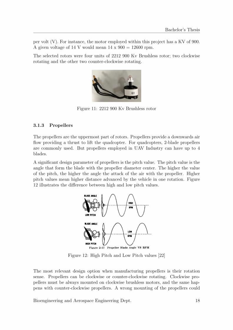
per volt (V). For instance, the motor employed within this project has a KV of 900.A given voltage of 14 V would mean 14 x 900 = 12600 rpm.
The selected rotors were four units of 2212 900 Kv Brushless rotor; two clockwiserotating and the other two counter-clockwise rotating.
Figure 11: 2212 900 Kv Brushless rotor
3.1.3 Propellers
The propellers are the uppermost part of rotors. Propellers provide a downwards airflow providing a thrust to lift the quadcopter. For quadcopters, 2-blade propellersare commonly used. But propellers employed in UAV Industry can have up to 4blades.
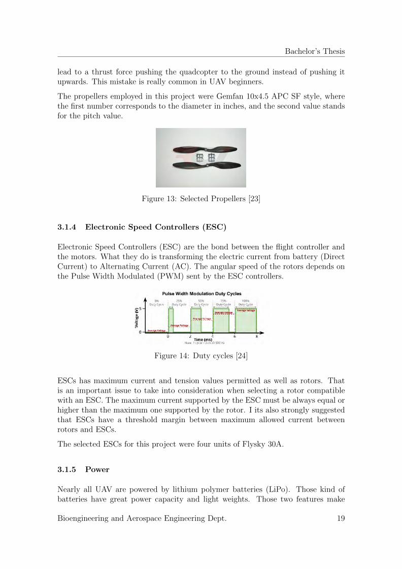
A significant design parameter of propellers is the pitch value. The pitch value is theangle that form the blade with the propeller diameter center. The higher the valueof the pitch, the higher the angle the attack of the air with the propeller. Higherpitch values mean higher distance advanced by the vehicle in one rotation. Figure12 illustrates the difference between high and low pitch values.
Figure 12: High Pitch and Low Pitch values [22]
The most relevant design option when manufacturing propellers is their rotationsense. Propellers can be clockwise or counter-clockwise rotating. Clockwise pro-pellers must be always mounted on clockwise brushless motors, and the same hap-pens with counter-clockwise propellers. A wrong mounting of the propellers could
Bioengineering and Aerospace Engineering Dept. 18
Bachelor’s Thesis
lead to a thrust force pushing the quadcopter to the ground instead of pushing itupwards. This mistake is really common in UAV beginners.
The propellers employed in this project were Gemfan 10x4.5 APC SF style, wherethe first number corresponds to the diameter in inches, and the second value standsfor the pitch value.
Figure 13: Selected Propellers [23]
3.1.4 Electronic Speed Controllers (ESC)
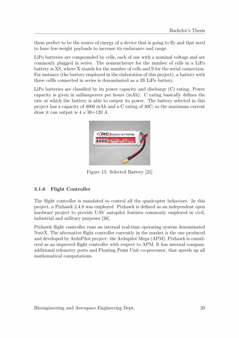
Electronic Speed Controllers (ESC) are the bond between the flight controller andthe motors. What they do is transforming the electric current from battery (DirectCurrent) to Alternating Current (AC). The angular speed of the rotors depends onthe Pulse Width Modulated (PWM) sent by the ESC controllers.
Figure 14: Duty cycles [24]
ESCs has maximum current and tension values permitted as well as rotors. Thatis an important issue to take into consideration when selecting a rotor compatiblewith an ESC. The maximum current supported by the ESC must be always equal orhigher than the maximum one supported by the rotor. I its also strongly suggestedthat ESCs have a threshold margin between maximum allowed current betweenrotors and ESCs.
The selected ESCs for this project were four units of Flysky 30A.
3.1.5 Power
Nearly all UAV are powered by lithium polymer batteries (LiPo). Those kind ofbatteries have great power capacity and light weights. Those two features make
Bioengineering and Aerospace Engineering Dept. 19
Bachelor’s Thesis
them perfect to be the source of energy of a device that is going to fly and that needto have low-weight payloads to increase its endurance and range.
LiPo batteries are compounded by cells, each of one with a nominal voltage and arecommonly plugged in series. The nomenclature for the number of cells in a LiPobattery is XS, where X stands for the number of cells and S for the serial connection.For instance (the battery employed in the elaboration of this project), a battery withthree cellls connected in series is denominated as a 3S LiPo battery.
LiPo batteries are classified by its power capacity and discharge (C) rating. Powercapacity is given in miliamperers per hours (mAh). C rating basically defines therate at which the battery is able to output its power. The battery selected in thisproject has a capacity of 4000 mAh and a C rating of 30C; so the maximum currentdraw it can output is 4 x 30=120 A.
Figure 15: Selected Battery [25]
3.1.6 Flight Controller
The flight controller is mandated to control all the quadcopter behaviors. In thisproject, a Pixhawk 2.4.8 was employed. Pixhawk is defined as an independent openhardware project to provide UAV autopilot features commonly employed in civil,industrial and military purposes [26].
Pixhawk flight controller runs an internal real-time operating system denominatedNuttX. The alternative flight controller currently in the market is the one producedand developed by ArduPilot project: the Ardupilot Mega (APM). Pixhawk is consid-ered as an improved flight controller with respect to APM. It has internal compass,additional telemetry ports and Floating Point Unit co-processor, that speeds up allmathematical computations.
Bioengineering and Aerospace Engineering Dept. 20
Bachelor’s Thesis
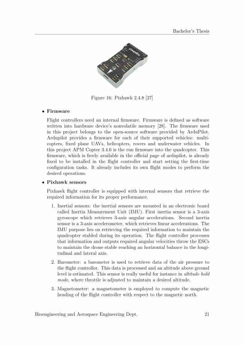
Figure 16: Pixhawk 2.4.8 [27]
• Firmware
Flight controllers need an internal firmware. Firmware is defined as softwarewritten into hardware device’s nonvolatile memory [28]. The firmware usedin this project belongs to the open-source software provided by ArduPilot.Ardupilot provides a firmware for each of their supported vehicles: multi-copters, fixed plane UAVs, helicopters, rovers and underwater vehicles. Inthis project APM Copter 3.4.6 is the run firmware into the quadcopter. Thisfirmware, which is freely available in the official page of ardupilot, is alreadyfixed to be installed in the flight controller and start setting the first-timeconfiguration tasks. It already includes its own flight modes to perform thedesired operations.
• Pixhawk sensors
Pixhawk flight controller is equipped with internal sensors that retrieve therequired information for its proper performance.
1. Inertial sensors: the inertial sensors are mounted in an electronic boardcalled Inertia Measurement Unit (IMU). First inertia sensor is a 3-axisgyroscope which retrieves 3-axis angular accelerations. Second inertiasensor is a 3-axis accelerometer, which retrieves linear accelerations. TheIMU purpose lies on retrieving the required information to maintain thequadcopter stabled during its operation. The flight controller processesthat information and outputs required angular velocities throw the ESCsto maintain the drone stable reaching an horizontal balance in the longi-tudinal and lateral axis.
2. Barometer: a barometer is used to retrieve data of the air pressure tothe flight controller. This data is processed and an altitude above groundlevel is estimated. This sensor is really useful for instance in altitude holdmode, where throttle is adjusted to maintain a desired altitude.
3. Magnetometer: a magnetometer is employed to compute the magneticheading of the flight controller with respect to the magnetic north.
Bioengineering and Aerospace Engineering Dept. 21

Bachelor’s Thesis
4. External sensors: external sensors can be plugged into the Pixhawk flightcontroller throw the I2C, SPI and Serial ports. A critical sensor neededfor the proper performance of guided flight modes is a GPS sensor, whichis plugged into the Pixhawk by the GPS port. It can also be connected anadditional compass(magnetometer) through the I2C port. An additionalmagnetometer helps the system to retrieve more precised headings, basedon the comparison of the electromagnetic fields measured in the internalmagnetometer of the Pixhawk and the external one.
• Safety switch and Buzzer
Pixhawk flight controller kit includes a safety switch and a buzzer.
The aim of the safety switch is blocking the PWM communication between theflight controller and the ESCs, to allow safe UAV manipulations even whenthe battery is connected.
The buzzer is a device that emits different kind of sounds depending on thestatus of the quadcopter. It is a manner of communication between the flightcontroller and the pilot without the use of the Ground Control station. Forinstance, when the UAV is armed, it emits a characteristic bip for two seconds.
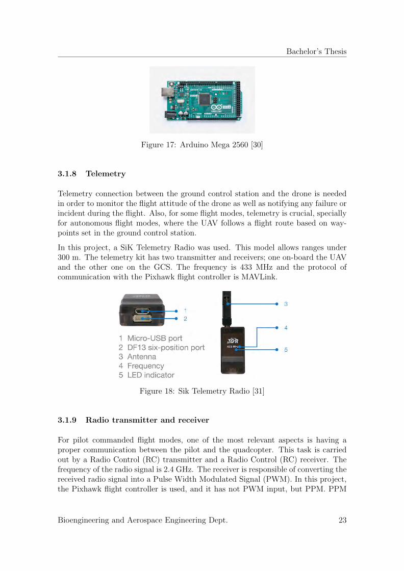
3.1.7 Arduino Mega 2560
Arduino Mega 2560 is a single-board microcontroller. It is the main hardware deviceof the collision avoidance system together with the ultrasonic rangefinders.
Arduino is an open source computer hardware and software company that producesmicrocontroller kits employed on building digital devices whose main applicationsare sensing and object controlling in the physical and digital world [29].
In this project, the purpose of the Arduino Mega 2560 board is processing all thedistance sensor information, and based on that, emitting the collision avoidancemotion maneuver order to the flight controller. In particular, it sends overwritingvalues of the pitch or roll (depending of the location of the obstacle) in order tomake the drone move away from the obstacle. The link between the arduino andthe Pixhawk flight controller is established through serial communication, by theUniversal Asynchronous Receiver/Transmitter (UART) hardware-integrated circuit,used for serial communication through the serial port. Further details about theconnections between the components are given in following sections.
Bioengineering and Aerospace Engineering Dept. 22
Bachelor’s Thesis
Figure 17: Arduino Mega 2560 [30]
3.1.8 Telemetry
Telemetry connection between the ground control station and the drone is neededin order to monitor the flight attitude of the drone as well as notifying any failure orincident during the flight. Also, for some flight modes, telemetry is crucial, speciallyfor autonomous flight modes, where the UAV follows a flight route based on way-points set in the ground control station.
In this project, a SiK Telemetry Radio was used. This model allows ranges under300 m. The telemetry kit has two transmitter and receivers; one on-board the UAVand the other one on the GCS. The frequency is 433 MHz and the protocol ofcommunication with the Pixhawk flight controller is MAVLink.
Figure 18: Sik Telemetry Radio [31]
3.1.9 Radio transmitter and receiver
For pilot commanded flight modes, one of the most relevant aspects is having aproper communication between the pilot and the quadcopter. This task is carriedout by a Radio Control (RC) transmitter and a Radio Control (RC) receiver. Thefrequency of the radio signal is 2.4 GHz. The receiver is responsible of converting thereceived radio signal into a Pulse Width Modulated Signal (PWM). In this project,the Pixhawk flight controller is used, and it has not PWM input, but PPM. PPM
Bioengineering and Aerospace Engineering Dept. 23
Bachelor’s Thesis
stands for pulse position modulation. In PPM, the signal is conformed by a set ofpulses of fixed length. Between the pulses, there are pauses of variable length.
Therefore, a PPM encoder was used to convert the PWM signal from the RC receiverto PPM to input the Pixhawk flight controller. So, the PWM signals of each of the 5used channels (roll, pitch, yaw, throttle and flight mode) are all encoded in a singlePPM signal. Since the the Flysky FS-i6 RC transmitter employed in this projecthas six channels, the remaining one is not used. This channel without use could beapplied for servo motor control for instance, usually used when a camera as payloadis on-board the quadcopter.
Figure 19: Flysky FS-i6 RC transmitter and receiver [32]
3.1.10 Ultrasonic range finder
Ultrasonic range finder is a SoNAR sensor and it has the work principle explainedin Section 2.2.2. The utilized sensor in this project is the HC-SR04 sonar, whichis connected to the Arduino Mega 2560 microcontroller board, where the sensordistance processing takes place.
Figure 20: HC-SR04 Ultrasonic Finder [33]
3.2 Software elements
3.2.1 Ubuntu 16.04
The operating system employed in this project is Ubuntu 16.04. It is a free and opensource operating system based on Debian. The open-source software used within the
Bioengineering and Aerospace Engineering Dept. 24
Bachelor’s Thesis
development of this project is run in this operating system.
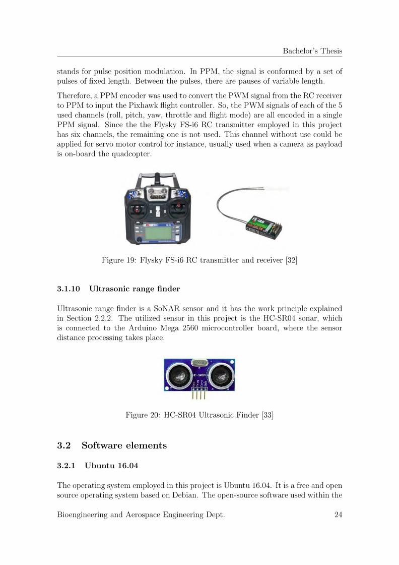
3.2.2 APM Planner
ArduPilot is an open source, unmanned vehicle AutoPilot Software suite, developedwith the main objective of guiding and controlling unmanned systems. It providessoftware running on the vehicle controller (i.e. the firmware); as well as groundcontrol station software such as Mission Planner, APM Planner, QGroundControlor MavProxy. Mission Planner is the Ground Control Station software utilized bymost of the users. However, it is only supported in Windows. Since the operatingsystem employed within this project is Ubuntu 16.04; the available and compatibleGCS software has been APM Planner 2.
Ground control station software is very useful for advanced missions and propercalibration of the vehicles, when it is necessary to tune the control parameters thatcontrol loop necessitate for real-time computations. When connecting the vehicle toa GCS, the control does not lie only on the 6 channels of the RC transmitter. High-level commands can be sent from Ground Control station to the vehicle, as well asmonitoring real-time information of the attitude and state of the UAV. The vehiclecan be connected to the GCS by USB wire connection to upload the firmware andperform the calibration procedures. But when the quadcopter is on the air, all realtime information monitoring and advanced commands sending (for guiding modes)is performed via telemetry connection, whose hardware was introduced in section3.1.8.
Figure 21: Arduino IDE interface[34]
Bioengineering and Aerospace Engineering Dept. 25
Bachelor’s Thesis
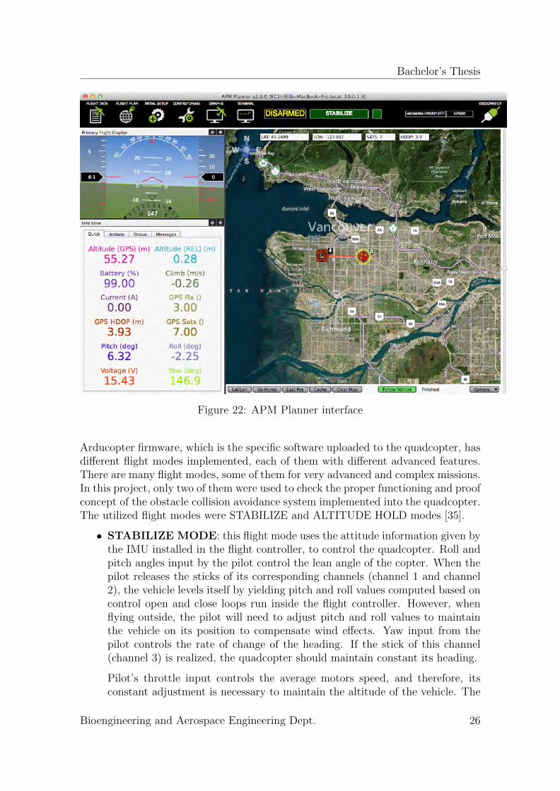
Figure 22: APM Planner interface
Arducopter firmware, which is the specific software uploaded to the quadcopter, hasdifferent flight modes implemented, each of them with different advanced features.There are many flight modes, some of them for very advanced and complex missions.In this project, only two of them were used to check the proper functioning and proofconcept of the obstacle collision avoidance system implemented into the quadcopter.The utilized flight modes were STABILIZE and ALTITUDE HOLD modes [35].
• STABILIZE MODE: this flight mode uses the attitude information given bythe IMU installed in the flight controller, to control the quadcopter. Roll andpitch angles input by the pilot control the lean angle of the copter. When thepilot releases the sticks of its corresponding channels (channel 1 and channel2), the vehicle levels itself by yielding pitch and roll values computed based oncontrol open and close loops run inside the flight controller. However, whenflying outside, the pilot will need to adjust pitch and roll values to maintainthe vehicle on its position to compensate wind effects. Yaw input from thepilot controls the rate of change of the heading. If the stick of this channel(channel 3) is realized, the quadcopter should maintain constant its heading.
Pilot’s throttle input controls the average motors speed, and therefore, itsconstant adjustment is necessary to maintain the altitude of the vehicle. The
Bioengineering and Aerospace Engineering Dept. 26
Bachelor’s Thesis
throttle sent to the rotors is adjusted automatically based on the tilt angle ofthe vehicle, to reduce compensation from the pilot when attitude changes [36].
• ALTITUDE HOLD MODE: yaw, pitch and roll angles operate in the sameway as in the Stabilize Mode. However, in this mode, the throttle is adjusted tomaintain a constant altitude, based on the tilt angle and pressure informationretrieved from IMU and barometer sensors installed inside the flight controller.
3.2.3 Arduino IDE
The Arduino integrated development environment (IDE) is a cross platform appli-cation written in Java. It provides a code editor, with simple one-click mechanismsto compile and upload programs to the arduino board [29]. Additionally, it providesmessage area, text console, toolbar with buttons for usual functions and hierarchyof operation menus.
Arduino IDE supports C and C++ programming languages. The code writing onlyentails two main functions:
• Setup: initializing the variables and constants.
• Loop: main program loop.
Arduino IDE utilizes the program ’avrdude’ to transform the executable code intoan hexadecimal text file loaded to the Arduino micro-controller board by a loaderprogram.
In this project, a program is developed in an arduino sketch to process the distanceinput data from the sensors and output specific overriding values to change thetrajectory of the quadcopter and avoid a collision.
3.3 Communications
As mentioned in previous sections, a quadcopter can be controlled by two possibleways. First one is by direct control of the pilot through a RC transmitter. Secondone is by ground control station link through a telemetry radio installed in both,GCS and the vehicle.
3.3.1 RC control
This is the simplest way of controlling an UAV. It is mostly employed in civil useand leisure flights. All the channels remain under the control of the pilot, whichshould be trained properly to command the drone.
Bioengineering and Aerospace Engineering Dept. 27
Bachelor’s Thesis
Figure 23: RC transmitter Euler angles and throttle sticks [37]
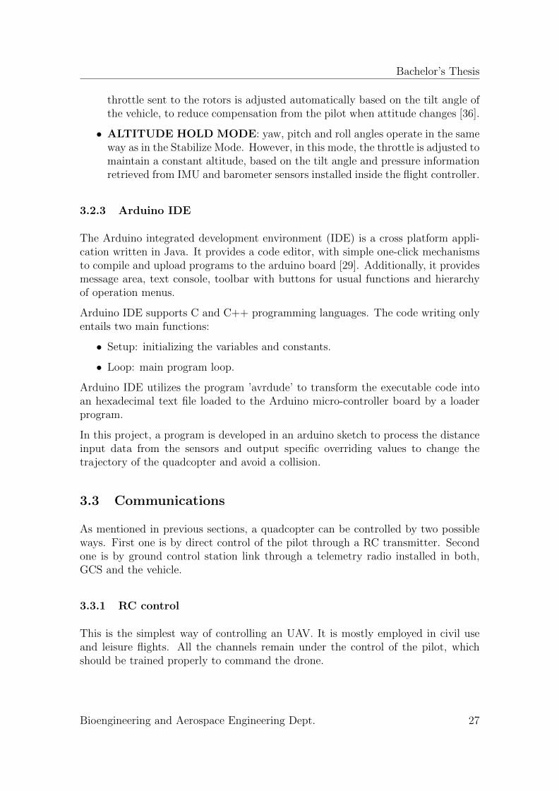
The four basic necessary channels to command a drone are the Euler angles and thethrottle, as depicted in Figure 23. In this project, it is also used the fifth channelto control the flight mode of the drone. The information is sent to the RC receiverthrow radio waves. The receiver converts this signal to PWM for each of the sixchannels and send it to the PPM encoder, which transfer the PPM signal to theflight controller.
3.3.2 MAVLink
MAVLink stands for Micro Air Vehicle Link, and is a protocol of communicationdeveloped with the purpose of information exchange between a GCS and MAVs. Itwas designed by creating small and light libraries containing the needed informationfor the interchange of sent and receive messages during GCS-MAV communication.MAVLink is pretty feasibly adaptable in any kind of GCS and vehicle, since themessage definition is written in C. In spite of the current libraries have a wide rangeof messages, new messages can be created by users by developing new libraries [38].
The messages are byte-encrypted, and can be understood and interpreted by theGCS, the flight controller, or an additional micro-controller board as Arduino Mega2560, the one utilized within this project. Messages such as heartbeat, arming,disarming, flight mode change or overwriting channels can be instructed by the GCSor a micro-controller board, and immediately thereafter interpreted and executed bythe flight controller.
The MAVLink package consists of a codified sequence of bytes. Table 2 shows thestructure and function of each of the bytes that conform a message package.
Among the autopilots that support this protocol of communication, there are manyof them [38]:
• Autopilots: ArduPilot Mega, pxIMU Autopilot, SLUGS Autopilot, FLEX-IPILOT, MatrixPilot, SenseSoar Autopilot, SmartAP Autopilo, AUtoQuad 6AutoPilot, Pixhawk Autopilot.
Bioengineering and Aerospace Engineering Dept. 28

Bachelor’s Thesis
Table 2: MAVLink bytes explanation
Byte Index Byte Explanation0 Start Flag the start of a new packet
1 LongitudeGives the longitude of the payload,in number of bytes, from 0 to 255bytes.
2 SequenceGives a sequence number to the sendmessage in order to order them in thereceiver target system.
3 System IDIdentifies the number of the sendingsystem, letting to distinguish betweendifferent sending systems.
4 Component IDIdentifies the component inside thesending system that has sent thecommand.
5 Message ID
Identifies the kind of sent message,so the receiving target knowshow to read and interpret the receivedmessage.
6+nn=[0-255 bytes]
PayloadThe payload can be conformed from 0 to255 bytes and contains the contentof the message itself.
[n+7,n+8] Checksum
This last part of the message can weigh1 or 2 bytes and its purpose is the controlof mistakes, protecting the packet fromdecoding it in the wrong way.
Bioengineering and Aerospace Engineering Dept. 29
Bachelor’s Thesis
• GCS Software: iDroneCtrl, QGroundControl, HK Ground Control Station,APM Planner, Mission Planner, MAVProxy.
One of the key aims of this project, as well as a tough objective, is creating aproper communication link among the main components of the UAV. Integrating theObstacle Collision Avoidance System into the rest of the UAV had many difficulties.Undoubtedly, one of them was establish a MAVLink communication between thearduino board and the flight controller. The required maneuver execution orderwere sent from the Arduino Mega 2560 by MAVLink protocol of communication.
This task was done following a systematic approach, from very simple commandstesting, to more complicated ones, finalizing in a successful concept proof of a colli-sion avoidance maneuver.
It is also remarkable to take into the account that the distance data processingdid not have nothing to do with MAVLink. A program was created to process thatinformation inside the arduino board, and based on that, sending through MAVLinkoverwriting values of Euler angles to perform the maneuver. Therefore, the utilityof MAVLink protocol of communication within this project lied on sending attitudecorrections, instead of distances.
MAVLink communication is established in this project throw two physical connec-tions:
• USB connection: established through serial communication, by the Univer-sal Asynchronous Receiver/Transmitter (UART) hardware-integrated circuit,when the Pixhawk flight controller is connected to the GCS to perform cali-brations and firmware updates; and for the arduino Mega 2560-flight controllerconnection.
• Radio telemetry connection: when the quadcopter is flying, to monitor inthe GCS real-time information and to define control parameter values in theGCS without the need of disarming the vehicle.
Bioengineering and Aerospace Engineering Dept. 30

Bachelor’s Thesis
4 Collision Avoidance System Design
In this section, the sensing and collision avoidance system design will be introduced.
4.1 Collision Avoidance System Requirements
First step prior to the design of any subsystem, consist on setting the requirementsto be fulfilled. A model of classification based on INCOSE system requirements [39]was followed, as shown in table 3.
Table 3: Collision avoidance system requirements
Req. ID RequirementFunctionality
1.1The collision avoidance system should detect the obstacleslocated on each of its four sides.
1.2The collision avoidance system should constantly detect thealtitude at which the MAV flies.
1.3The collision avoidance system should maintain the MAVLINKcommunication link with the flight controller every time.
1.4The collision avoidance system should successfully process thereceived distance data.
1.5The collision avoidance system should successfully command amaneuver to avoid a collision.
Integration
2.1The collision avoidance system shall be successfullyimplemented in the MAV.
Performance
3.1Each of the four lateral ultrasonic range finders should beoperative among the whole mission.
3.2Each of the four lateral ultrasonic range finders should bepowered among the whole mission.
3.3The ultrasonic waves should propagate successfully within theenvironment where the MAV operates.
3.4The ultrasonic range finder located in the bottom of the quadcoptershould be operative among the whole mission.
3.5The ultrasonic range finder located in the bottom of the quadcoptershould be powered among the whole mission.
Bioengineering and Aerospace Engineering Dept. 31
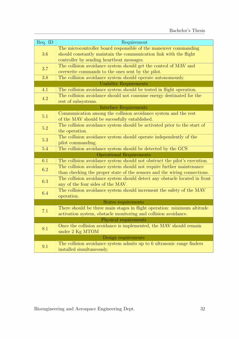
Bachelor’s Thesis
Req. ID Requirement
3.6The microcontroller board responsible of the maneuver commandingshould constantly maintain the communication link with the flightcontroller by sending heartbeat messages.
3.7The collision avoidance system should get the control of MAV andoverwrite commands to the ones sent by the pilot.
3.8 The collision avoidance system should operate autonomously.Usability Requirements
4.1 The collision avoidance system should be tested in flight operation.
4.2The collision avoidance should not consume energy destinated for therest of subsystems.
Interface Requirements
5.1Communication among the collision avoidance system and the restof the MAV should be sucessfully entablished.
5.2The collision avoidance system should be activated prior to the start ofthe operation.
5.3The collision avoidance system should operate independently of thepilot commanding.
5.4 The collision avoidance system should be detected by the GCSOperational Requirements
6.1 The collision avoidance system should not obstruct the pilot’s execution.
6.2The collision avoidance system should not require further maintenancethan checking the proper state of the sensors and the wiring connections.
6.3The collision avoidance system should detect any obstacle located in frontany of the four sides of the MAV.
6.4The collision avoidance system should increment the safety of the MAVoperation.
States requirements
7.1There should be three main stages in flight operation: minimum altitudeactivation system, obstacle monitoring and collision avoidance.
Physical requirements
8.1Once the collision avoidance is implemented, the MAV should remainunder 2 Kg MTOM
Design requirements
9.1The collision avoidance system admits up to 6 ultrasonic range findersinstalled simultaneously.
Bioengineering and Aerospace Engineering Dept. 32
Bachelor’s Thesis
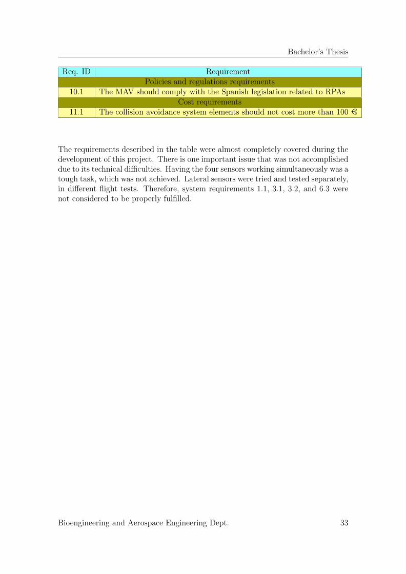
Req. ID RequirementPolicies and regulations requirements
10.1 The MAV should comply with the Spanish legislation related to RPAsCost requirements
11.1 The collision avoidance system elements should not cost more than 100 €
The requirements described in the table were almost completely covered during thedevelopment of this project. There is one important issue that was not accomplisheddue to its technical difficulties. Having the four sensors working simultaneously was atough task, which was not achieved. Lateral sensors were tried and tested separately,in different flight tests. Therefore, system requirements 1.1, 3.1, 3.2, and 6.3 werenot considered to be properly fulfilled.
Bioengineering and Aerospace Engineering Dept. 33
Bachelor’s Thesis
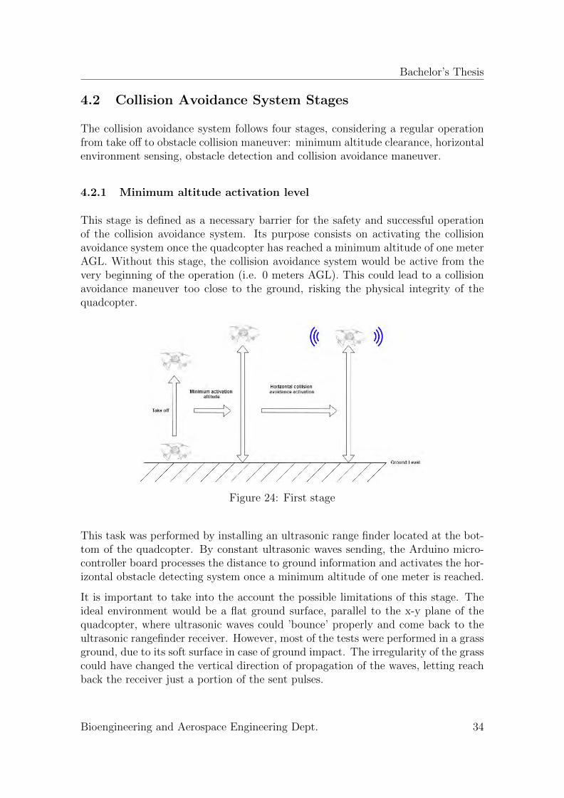
4.2 Collision Avoidance System Stages
The collision avoidance system follows four stages, considering a regular operationfrom take off to obstacle collision maneuver: minimum altitude clearance, horizontalenvironment sensing, obstacle detection and collision avoidance maneuver.
4.2.1 Minimum altitude activation level
This stage is defined as a necessary barrier for the safety and successful operationof the collision avoidance system. Its purpose consists on activating the collisionavoidance system once the quadcopter has reached a minimum altitude of one meterAGL. Without this stage, the collision avoidance system would be active from thevery beginning of the operation (i.e. 0 meters AGL). This could lead to a collisionavoidance maneuver too close to the ground, risking the physical integrity of thequadcopter.
Figure 24: First stage
This task was performed by installing an ultrasonic range finder located at the bot-tom of the quadcopter. By constant ultrasonic waves sending, the Arduino micro-controller board processes the distance to ground information and activates the hor-izontal obstacle detecting system once a minimum altitude of one meter is reached.
It is important to take into the account the possible limitations of this stage. Theideal environment would be a flat ground surface, parallel to the x-y plane of thequadcopter, where ultrasonic waves could ’bounce’ properly and come back to theultrasonic rangefinder receiver. However, most of the tests were performed in a grassground, due to its soft surface in case of ground impact. The irregularity of the grasscould have changed the vertical direction of propagation of the waves, letting reachback the receiver just a portion of the sent pulses.
Bioengineering and Aerospace Engineering Dept. 34
Bachelor’s Thesis
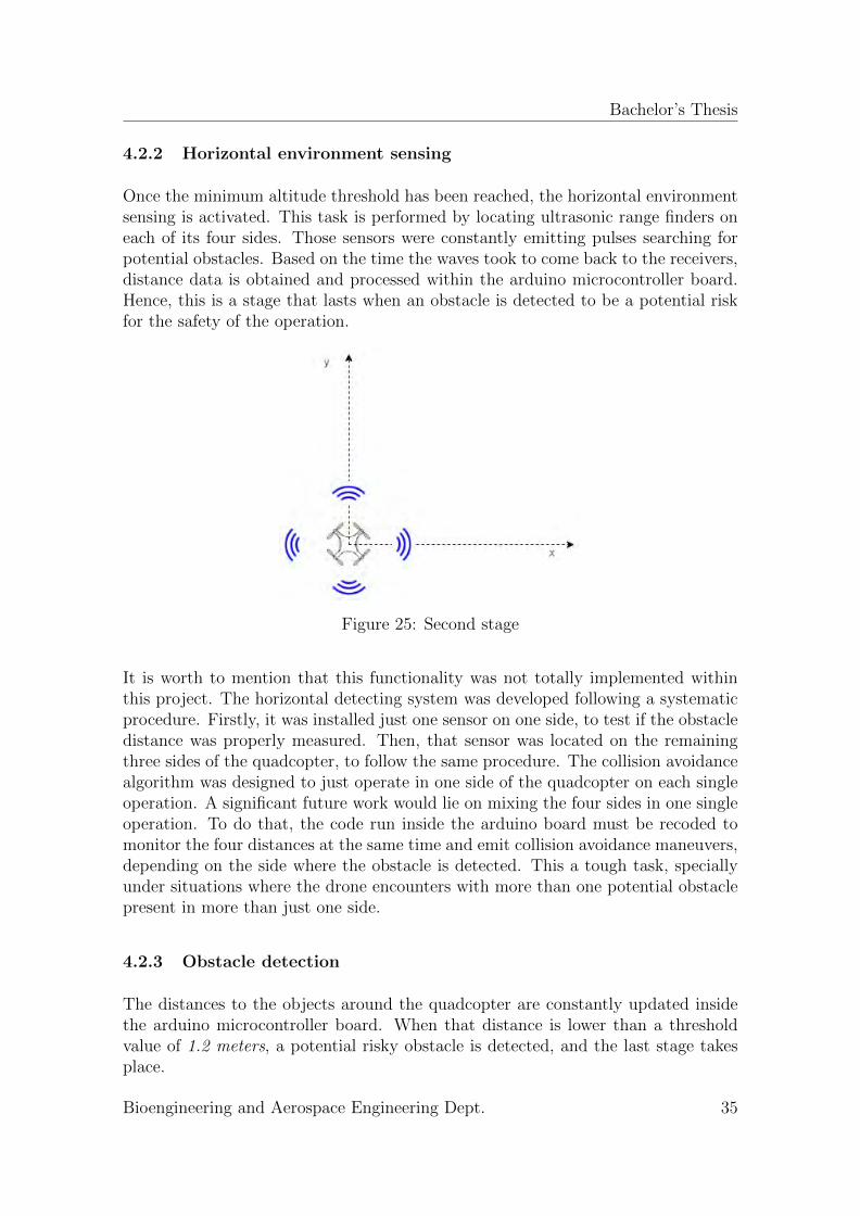
4.2.2 Horizontal environment sensing
Once the minimum altitude threshold has been reached, the horizontal environmentsensing is activated. This task is performed by locating ultrasonic range finders oneach of its four sides. Those sensors were constantly emitting pulses searching forpotential obstacles. Based on the time the waves took to come back to the receivers,distance data is obtained and processed within the arduino microcontroller board.Hence, this is a stage that lasts when an obstacle is detected to be a potential riskfor the safety of the operation.
Figure 25: Second stage
It is worth to mention that this functionality was not totally implemented withinthis project. The horizontal detecting system was developed following a systematicprocedure. Firstly, it was installed just one sensor on one side, to test if the obstacledistance was properly measured. Then, that sensor was located on the remainingthree sides of the quadcopter, to follow the same procedure. The collision avoidancealgorithm was designed to just operate in one side of the quadcopter on each singleoperation. A significant future work would lie on mixing the four sides in one singleoperation. To do that, the code run inside the arduino board must be recoded tomonitor the four distances at the same time and emit collision avoidance maneuvers,depending on the side where the obstacle is detected. This a tough task, speciallyunder situations where the drone encounters with more than one potential obstaclepresent in more than just one side.
4.2.3 Obstacle detection
The distances to the objects around the quadcopter are constantly updated insidethe arduino microcontroller board. When that distance is lower than a thresholdvalue of 1.2 meters, a potential risky obstacle is detected, and the last stage takesplace.
Bioengineering and Aerospace Engineering Dept. 35
Bachelor’s Thesis
Figure 26: Third stage
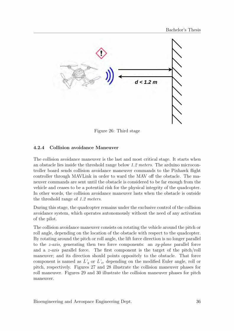
4.2.4 Collision avoidance Maneuver
The collision avoidance maneuver is the last and most critical stage. It starts whenan obstacle lies inside the threshold range below 1.2 meters. The arduino microcon-troller board sends collision avoidance maneuver commands to the Pixhawk flightcontroller through MAVLink in order to ward the MAV off the obstacle. The ma-neuver commands are sent until the obstacle is considered to be far enough from thevehicle and ceases to be a potential risk for the physical integrity of the quadcopter.In other words, the collision avoidance maneuver lasts when the obstacle is outsidethe threshold range of 1.2 meters.
During this stage, the quadcopter remains under the exclusive control of the collisionavoidance system, which operates autonomously without the need of any activationof the pilot.
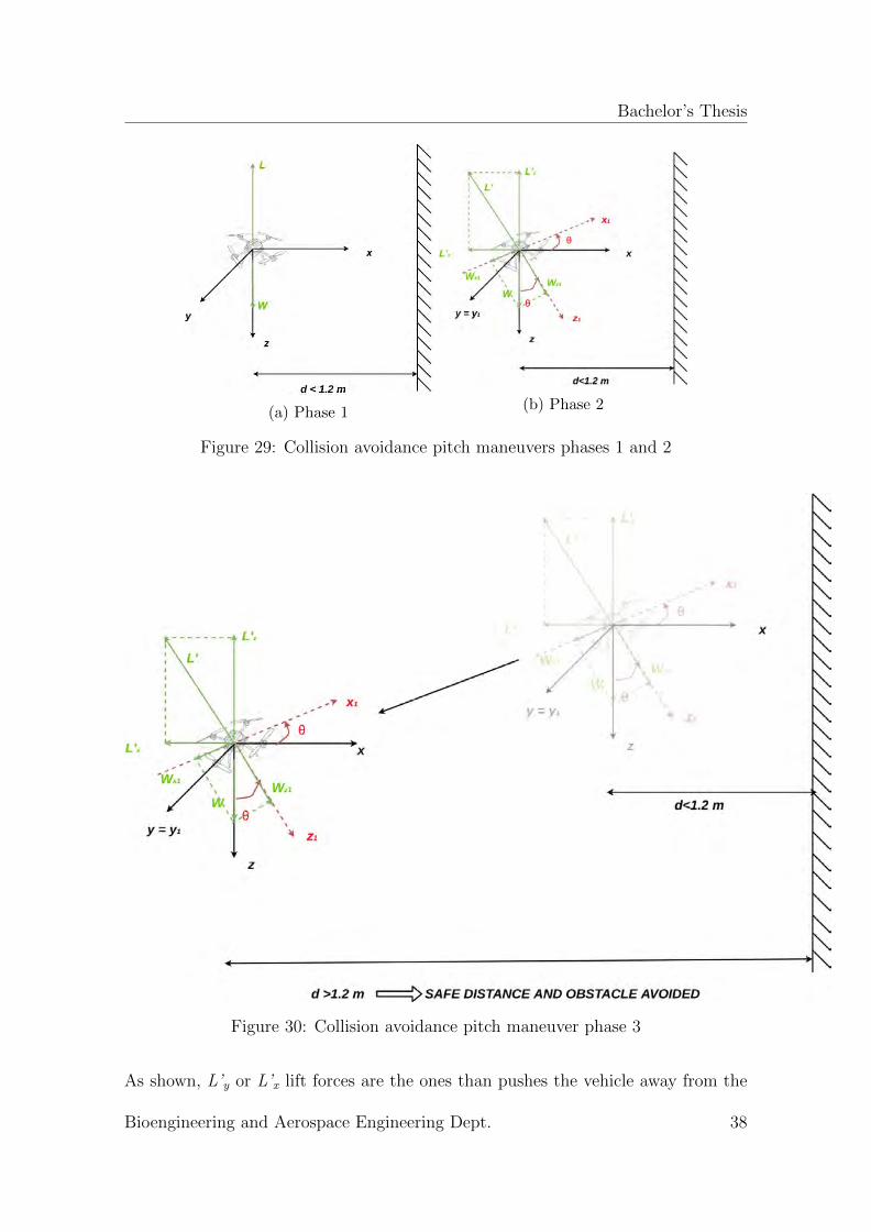
The collision avoidance maneuver consists on rotating the vehicle around the pitch orroll angle, depending on the location of the obstacle with respect to the quadcopter.By rotating around the pitch or roll angle, the lift force direction is no longer parallelto the z-axis, generating then two force components: an xy-plane parallel forceand a z-axis parallel force. The first component is the target of the pitch/rollmaneuver; and its direction should points oppositely to the obstacle. That forcecomponent is named as L’y or L’x, depending on the modified Euler angle, roll orpitch, respectively. Figures 27 and 28 illustrate the collision maneuver phases forroll maneuver. Figures 29 and 30 illustrate the collision maneuver phases for pitchmaneuver.
Bioengineering and Aerospace Engineering Dept. 36
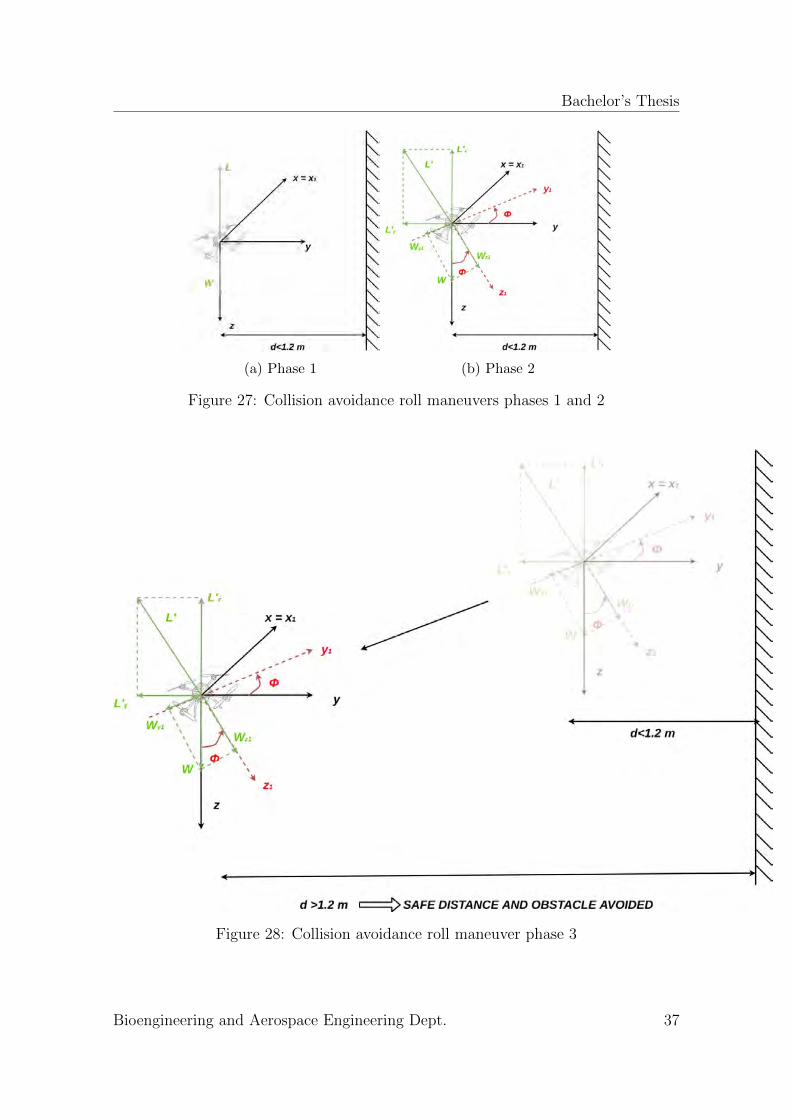
Bachelor’s Thesis
(a) Phase 1 (b) Phase 2
Figure 27: Collision avoidance roll maneuvers phases 1 and 2
Figure 28: Collision avoidance roll maneuver phase 3
Bioengineering and Aerospace Engineering Dept. 37
Bachelor’s Thesis
(a) Phase 1(b) Phase 2
Figure 29: Collision avoidance pitch maneuvers phases 1 and 2
Figure 30: Collision avoidance pitch maneuver phase 3
As shown, L’y or L’x lift forces are the ones than pushes the vehicle away from the
Bioengineering and Aerospace Engineering Dept. 38
Bachelor’s Thesis
obstacle. However, there is a drawback in this solution. Initially, the drone in phase1 is considered to be hovering, existing total equilibrium of forces, and the weightof the vehicle is compensated by the lift force provided by the rotors. When thevehicle rotates around the roll or pitch angle, the lift force changes its direction, andthe lift force component along the initial z-axis is no longer valid to compensatethe weight of the quadcopter. This provokes a descent of the vehicle towards theground, unless the lift (i.e.thrust) force is manually compensated by the pilot. Thisrelevant issue can be solved by changing the flight mode to altitude hold mode, aswill be explained in following sections.
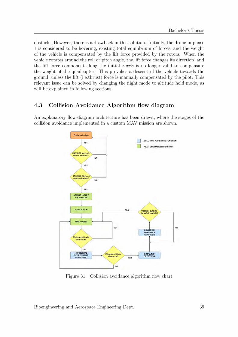
4.3 Collision Avoidance Algorithm flow diagram
An explanatory flow diagram architecture has been drawn, where the stages of thecollision avoidance implemented in a custom MAV mission are shown.
Figure 31: Collision avoidance algorithm flow chart
Bioengineering and Aerospace Engineering Dept. 39
Bachelor’s Thesis
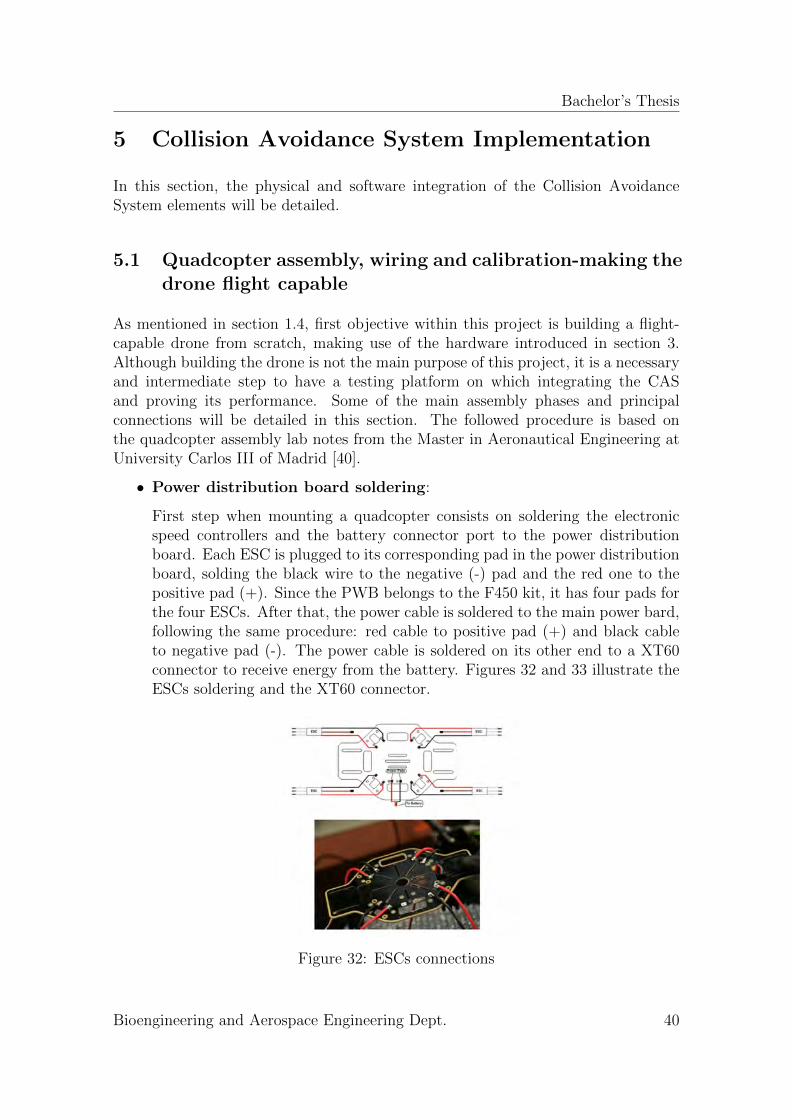
5 Collision Avoidance System Implementation
In this section, the physical and software integration of the Collision AvoidanceSystem elements will be detailed.
5.1 Quadcopter assembly, wiring and calibration-making thedrone flight capable
As mentioned in section 1.4, first objective within this project is building a flight-capable drone from scratch, making use of the hardware introduced in section 3.Although building the drone is not the main purpose of this project, it is a necessaryand intermediate step to have a testing platform on which integrating the CASand proving its performance. Some of the main assembly phases and principalconnections will be detailed in this section. The followed procedure is based onthe quadcopter assembly lab notes from the Master in Aeronautical Engineering atUniversity Carlos III of Madrid [40].
• Power distribution board soldering:
First step when mounting a quadcopter consists on soldering the electronicspeed controllers and the battery connector port to the power distributionboard. Each ESC is plugged to its corresponding pad in the power distributionboard, solding the black wire to the negative (-) pad and the red one to thepositive pad (+). Since the PWB belongs to the F450 kit, it has four pads forthe four ESCs. After that, the power cable is soldered to the main power bard,following the same procedure: red cable to positive pad (+) and black cableto negative pad (-). The power cable is soldered on its other end to a XT60connector to receive energy from the battery. Figures 32 and 33 illustrate theESCs soldering and the XT60 connector.
Figure 32: ESCs connections
Bioengineering and Aerospace Engineering Dept. 40
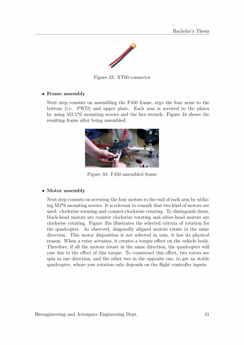
Bachelor’s Thesis
Figure 33: XT60 connector
• Frame assembly
Next step consists on assembling the F450 frame, ergo the four arms to thebottom (i.e. PWD) and upper plate. Each arm is screwed to the platesby using M2.5*6 mounting screws and the hex-wrench. Figure 34 shows theresulting frame after being assembled.
Figure 34: F450 assembled frame
• Motor assembly
Next step consists on screwing the four motors to the end of each arm by utiliz-ing M3*6 mounting screws. It is relevant to remark that two kind of motors areused: clockwise rotating and counter-clockwise rotating. To distinguish them,black-head motors are counter clockwise rotating and silver-head motors areclockwise rotating. Figure 35a illustrates the selected criteria of rotation forthe quadcopter. As observed, diagonally aligned motors rotate in the samedirection. This motor disposition is not selected in vain, it has its physicalreason. When a rotor actuates, it creates a torque effect on the vehicle body.Therefore, if all the motors rotate in the same direction, the quadcopter willyaw due to the effect of this torque. To counteract this effect, two rotors arespin in one direction, and the other two in the opposite one, to get an stablequadcopter, whose yaw rotation only depends on the flight controller inputs.
Bioengineering and Aerospace Engineering Dept. 41
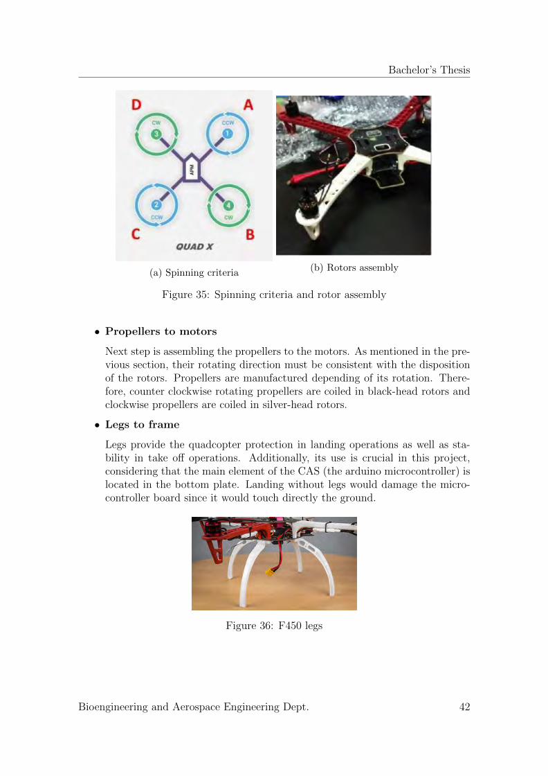
Bachelor’s Thesis
(a) Spinning criteria(b) Rotors assembly
Figure 35: Spinning criteria and rotor assembly
• Propellers to motors
Next step is assembling the propellers to the motors. As mentioned in the pre-vious section, their rotating direction must be consistent with the dispositionof the rotors. Propellers are manufactured depending of its rotation. There-fore, counter clockwise rotating propellers are coiled in black-head rotors andclockwise propellers are coiled in silver-head rotors.
• Legs to frame
Legs provide the quadcopter protection in landing operations as well as sta-bility in take off operations. Additionally, its use is crucial in this project,considering that the main element of the CAS (the arduino microcontroller) islocated in the bottom plate. Landing without legs would damage the micro-controller board since it would touch directly the ground.
Figure 36: F450 legs
Bioengineering and Aerospace Engineering Dept. 42
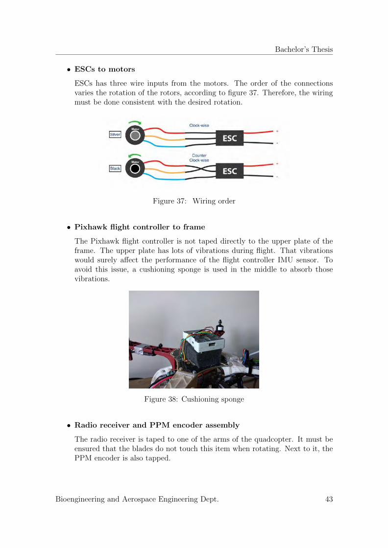
Bachelor’s Thesis
• ESCs to motors
ESCs has three wire inputs from the motors. The order of the connectionsvaries the rotation of the rotors, according to figure 37. Therefore, the wiringmust be done consistent with the desired rotation.
Figure 37: Wiring order
• Pixhawk flight controller to frame
The Pixhawk flight controller is not taped directly to the upper plate of theframe. The upper plate has lots of vibrations during flight. That vibrationswould surely affect the performance of the flight controller IMU sensor. Toavoid this issue, a cushioning sponge is used in the middle to absorb thosevibrations.
Figure 38: Cushioning sponge
• Radio receiver and PPM encoder assembly
The radio receiver is taped to one of the arms of the quadcopter. It must beensured that the blades do not touch this item when rotating. Next to it, thePPM encoder is also tapped.
Bioengineering and Aerospace Engineering Dept. 43
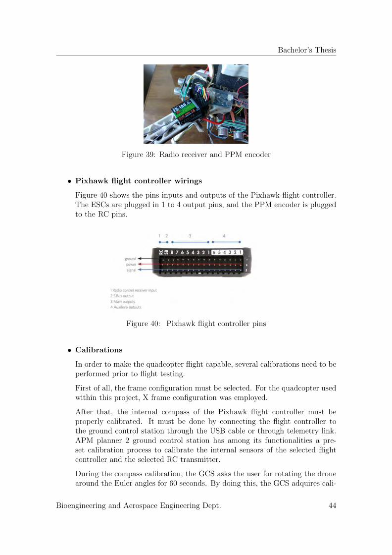
Bachelor’s Thesis
Figure 39: Radio receiver and PPM encoder
• Pixhawk flight controller wirings
Figure 40 shows the pins inputs and outputs of the Pixhawk flight controller.The ESCs are plugged in 1 to 4 output pins, and the PPM encoder is pluggedto the RC pins.
Figure 40: Pixhawk flight controller pins
• Calibrations
In order to make the quadcopter flight capable, several calibrations need to beperformed prior to flight testing.
First of all, the frame configuration must be selected. For the quadcopter usedwithin this project, X frame configuration was employed.
After that, the internal compass of the Pixhawk flight controller must beproperly calibrated. It must be done by connecting the flight controller tothe ground control station through the USB cable or through telemetry link.APM planner 2 ground control station has among its functionalities a pre-set calibration process to calibrate the internal sensors of the selected flightcontroller and the selected RC transmitter.
During the compass calibration, the GCS asks the user for rotating the dronearound the Euler angles for 60 seconds. By doing this, the GCS adquires cali-
Bioengineering and Aerospace Engineering Dept. 44
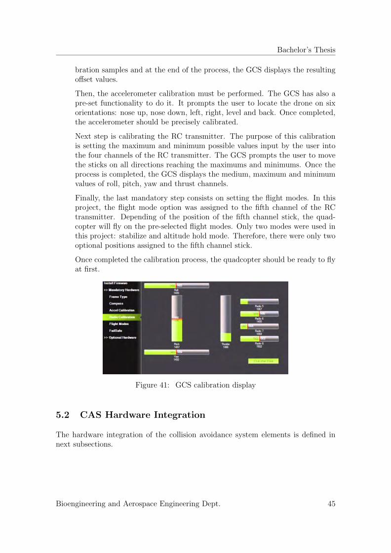
Bachelor’s Thesis
bration samples and at the end of the process, the GCS displays the resultingoffset values.
Then, the accelerometer calibration must be performed. The GCS has also apre-set functionality to do it. It prompts the user to locate the drone on sixorientations: nose up, nose down, left, right, level and back. Once completed,the accelerometer should be precisely calibrated.
Next step is calibrating the RC transmitter. The purpose of this calibrationis setting the maximum and minimum possible values input by the user intothe four channels of the RC transmitter. The GCS prompts the user to movethe sticks on all directions reaching the maximums and minimums. Once theprocess is completed, the GCS displays the medium, maximum and minimumvalues of roll, pitch, yaw and thrust channels.
Finally, the last mandatory step consists on setting the flight modes. In thisproject, the flight mode option was assigned to the fifth channel of the RCtransmitter. Depending of the position of the fifth channel stick, the quad-copter will fly on the pre-selected flight modes. Only two modes were used inthis project: stabilize and altitude hold mode. Therefore, there were only twooptional positions assigned to the fifth channel stick.
Once completed the calibration process, the quadcopter should be ready to flyat first.
Figure 41: GCS calibration display
5.2 CAS Hardware Integration
The hardware integration of the collision avoidance system elements is defined innext subsections.
Bioengineering and Aerospace Engineering Dept. 45
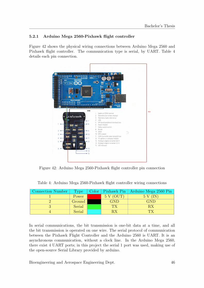
Bachelor’s Thesis
5.2.1 Arduino Mega 2560-Pixhawk flight controller
Figure 42 shows the physical wiring connections between Arduino Mega 2560 andPixhawk flight controller. The communication type is serial, by UART. Table 4details each pin connection.
Figure 42: Arduino Mega 2560-Pixhawk flight controller pin connection
Table 4: Arduino Mega 2560-Pixhawk flight controller wiring connections
Connection Number Type Color Pixhawk Pin Arduino Mega 2560 Pin1 Power 5 V (OUT) 5 V (IN)2 Ground GND GND3 Serial TX RX4 Serial RX TX
In serial communications, the bit transmission is one-bit data at a time, and allthe bit transmission is operated on one wire. The serial protocol of communicationbetween the Pixhawk Flight Controller and the Arduino 2560 is UART. It is anasynchronous communication, without a clock line. In the Arduino Mega 2560,there exist 4 UART ports; in this project the serial 1 port was used, making use ofthe open-source Serial Library provided by arduino.
Bioengineering and Aerospace Engineering Dept. 46
Bachelor’s Thesis
5.2.2 Arduino Mega 2560-Ultrasonic range finder HC-SR04
The HC-SR04 ultrasonic rangefinder works emitting a 40000 Hz ultrasonic wave thatpropagates through the medium until reaching an obstacle, where it ’bounces’ backto receiver sensor. The sensor is compounded by four pins: VCC, Ground, Trig andEcho:
• VCC: this is the input voltage pin. It must be connected to the 5 volts pin ofthe arduino board.
• GND: this is the ground pin. This pin acts as the reference point in theelectrical circuit from which the 5 voltage is measured. This pin must beconnected to the available GND pins in the Arduino Board.
• Trig pin: this pin must be plugged to any digital pin of the arduino board.In order to send a pulse, the digital pin of the arduino must be trig on highstate for at least 10 µs. By this, it will send a 8 cycle burst that will comeback after bouncing.
• Echo Pin: this pin must be connected to any digital pin of the arduino board.When the wave signals comes back; this pin will output in µs the time the timedifference between sending the pulse and receiving its reflection. By propercalculations as shown in section 2.2.2, the distance from the obstacle can becomputed.
Taking into the account that the arduino board has 12 digital pins, it can be con-nected up to 6 sensors (2 pins per sensor) and be operative simultaneously. Thischance can extend the obstacle collision avoidance problem to the six faces of thevehicle: four sides, bottom and top. In this project, five ultrasonic range finderswere used. One of them was located in the bottom of the quadcopter, working asa minimum altitude clearance device. The other four remaining ones were locatedon each of the four sides of the quadcopter, working as horizontal environmentalsensing devices.
Bioengineering and Aerospace Engineering Dept. 47

Bachelor’s Thesis
Table 5: Arduino Mega 2560-HC SR04 pin connections
Connection Number Type Color Arduino Mega 2560 Pin HC-SR04 Pin1 Power 5 V VCC2 Ground GND GND3 Trig Any digital Pin TRIG4 Echo Any Digital Pin ECHO
Figure 43: Arduino Mega 2560-HC-SR04 range finder pin connection
Table 5 details the pin connections between the Arduino board 2560 and the ultra-sonic range finder.
5.2.3 F450 kit-Ultrasonic range finder HC-SR04
As already stated, five ultrasonic range finders were implemented into the quad-copter. They were all assembled to the power distribution board of the quadcopteras shown in figure 44. The four lateral ones were carefully taped to maintain avertical alignment with the upward direction of the quadcopter. In that way, theultrasonic waves travel following a parallel direction to the ground and perpendic-ular to the obstacles test devices employed within the testing phase. Perpendicular’impact’ of the ultrasonic waves against the obstacles ensures that the waves aregoing to travel back to the receiver. Oblique impact makes lose some of the sentpulses, coming back just a portion of the reflected beats.
Bioengineering and Aerospace Engineering Dept. 48
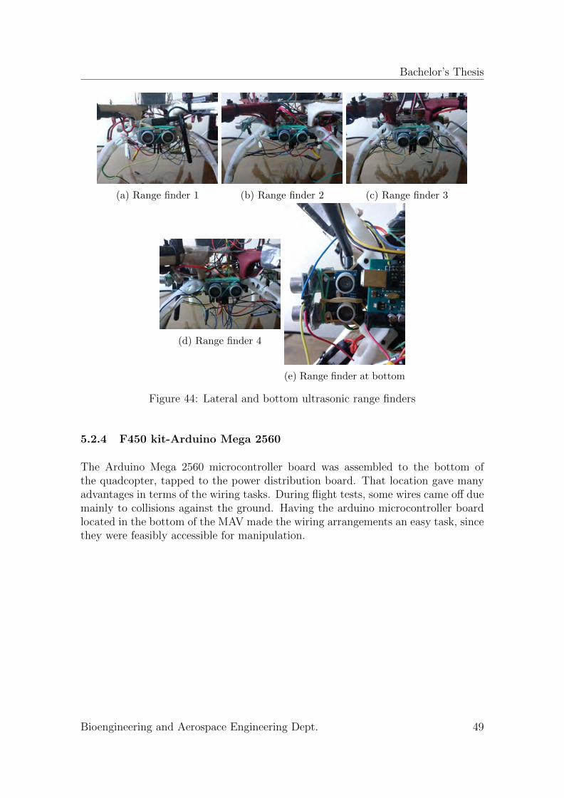
Bachelor’s Thesis
(a) Range finder 1 (b) Range finder 2 (c) Range finder 3
(d) Range finder 4
(e) Range finder at bottom
Figure 44: Lateral and bottom ultrasonic range finders
5.2.4 F450 kit-Arduino Mega 2560
The Arduino Mega 2560 microcontroller board was assembled to the bottom ofthe quadcopter, tapped to the power distribution board. That location gave manyadvantages in terms of the wiring tasks. During flight tests, some wires came off duemainly to collisions against the ground. Having the arduino microcontroller boardlocated in the bottom of the MAV made the wiring arrangements an easy task, sincethey were feasibly accessible for manipulation.
Bioengineering and Aerospace Engineering Dept. 49
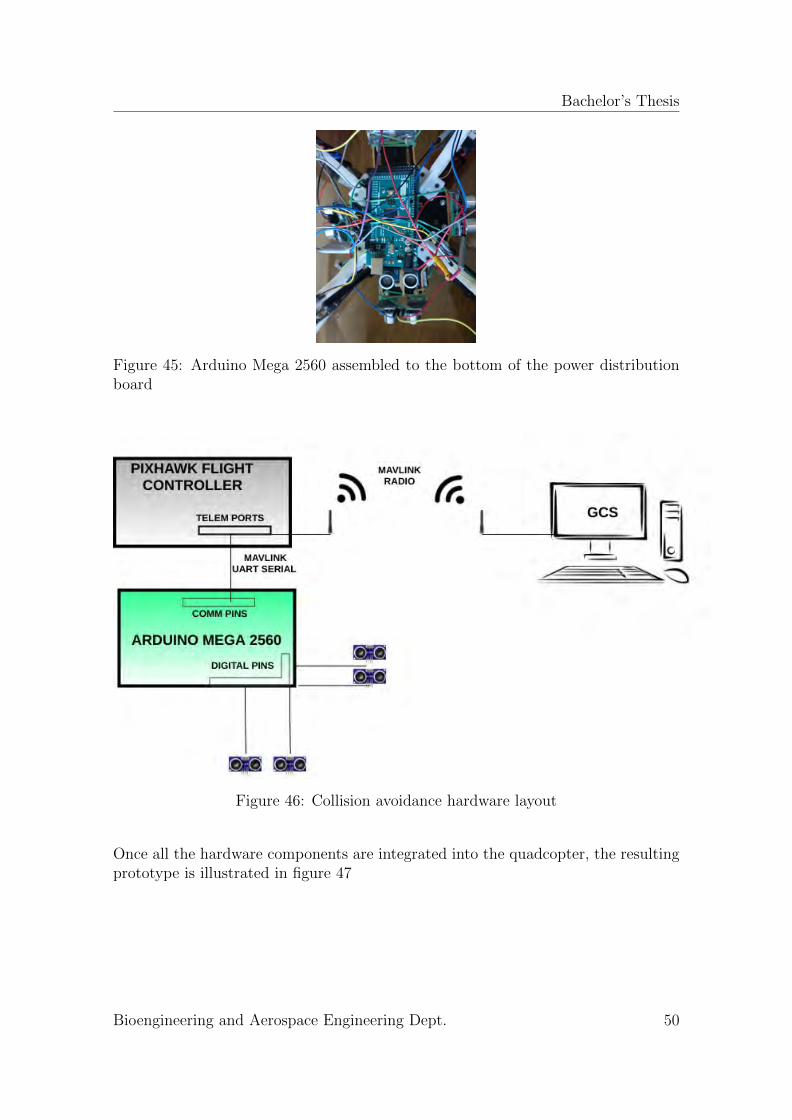
Bachelor’s Thesis
Figure 45: Arduino Mega 2560 assembled to the bottom of the power distributionboard
Figure 46: Collision avoidance hardware layout
Once all the hardware components are integrated into the quadcopter, the resultingprototype is illustrated in figure 47
Bioengineering and Aerospace Engineering Dept. 50
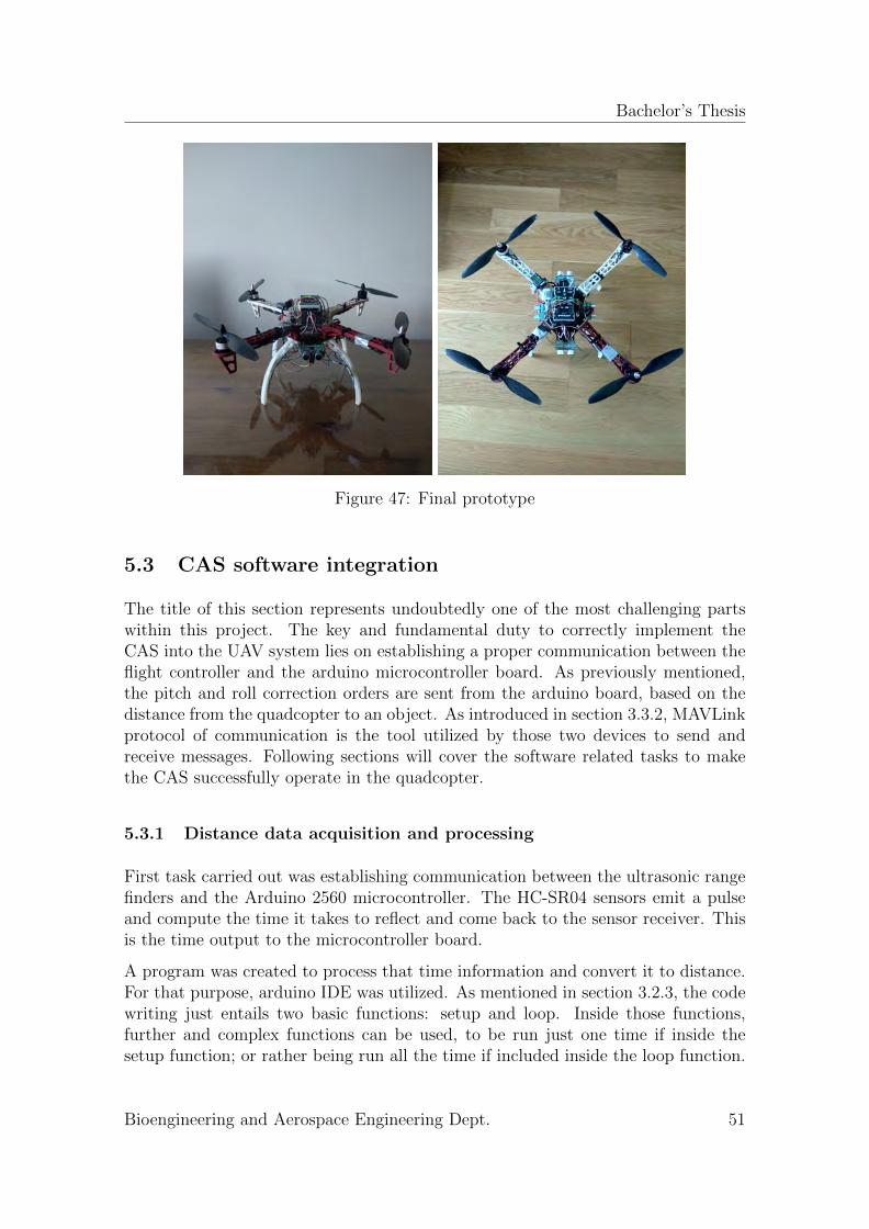
Bachelor’s Thesis
Figure 47: Final prototype
5.3 CAS software integration
The title of this section represents undoubtedly one of the most challenging partswithin this project. The key and fundamental duty to correctly implement theCAS into the UAV system lies on establishing a proper communication between theflight controller and the arduino microcontroller board. As previously mentioned,the pitch and roll correction orders are sent from the arduino board, based on thedistance from the quadcopter to an object. As introduced in section 3.3.2, MAVLinkprotocol of communication is the tool utilized by those two devices to send andreceive messages. Following sections will cover the software related tasks to makethe CAS successfully operate in the quadcopter.
5.3.1 Distance data acquisition and processing
First task carried out was establishing communication between the ultrasonic rangefinders and the Arduino 2560 microcontroller. The HC-SR04 sensors emit a pulseand compute the time it takes to reflect and come back to the sensor receiver. Thisis the time output to the microcontroller board.
A program was created to process that time information and convert it to distance.For that purpose, arduino IDE was utilized. As mentioned in section 3.2.3, the codewriting just entails two basic functions: setup and loop. Inside those functions,further and complex functions can be used, to be run just one time if inside thesetup function; or rather being run all the time if included inside the loop function.
Bioengineering and Aerospace Engineering Dept. 51
Bachelor’s Thesis
The distance function was included inside the loop of the arduino sketch; hence,pulses were constantly sent to monitor the environment.
As explained in section 4.2.1 the quadcopter needs to exceed a minimum altitude of1 meter to start monitoring the horizontal surrounding environment. That minimumaltitude level requisite is implemented as a mandatory condition to make the lateralultrasonic range finders work.
The collision avoidance system was integrated into the four sides of the quadcopter.However, the arduino program was designed to just activate one of the four sides oneach flight. In other words, four different programs were created depending on thedesired side of the drone where testing the collision avoidance system.
5.3.2 Arduino board as an UAV system
The collision avoidance system works sending pitch and roll corrections to change thetrajectory of the drone and ward it off from obstacles. Those pitch and roll correc-tions are overwritten to the ones imposed by the pilot through the RC transmitter.To achieve fortunate overwriting messages, the collision avoidance system must befirstly identified by the GCS as an additional UAV system. That identification iscarried out by establishing communication between the arduino microcontroller andthe Pixhawk flight controller. For that end, MAVLink protocol of communication isemployed.
MAVLink has a wide range of messages to send and receive from GCS, flight con-trollers and additional microcontroller boards. For the identification of the ArduinoMega 2560, the heartbeat message is utilized. Heartbeat message purpose lies onidentification of two subsystems and establishing proper link between them. Thismessage must be sent from the arduino board to the Pixhawk flight controller con-stantly, to inform the flight controller that the collision avoidance subsystem is stillalive. In case of not receiving the heartbeat pulses, the flight controller would ini-tiate a fail-safe system and would inform the GCS about the failure of the collisionavoidance system. Figure 48 and 49 show the proper identification of the collisionavoidance as a subsystem and its failure when the communications are lost, respec-tively.
The heartbeat message has the byte structure introduced in table 2 on section 3.3.2.The Pixhawk flight controller must be informed about the start of the message, itslongitude, the sequence number, the sending system ID, the sending component ID(the arduino board), the message ID (heartbeat message is enumerated as 0), thepayload and the checksum. All this information is prepacked in a function run inthe arduino board and sent through the serial1 port to the Pixhawk flight controller.
Bioengineering and Aerospace Engineering Dept. 52
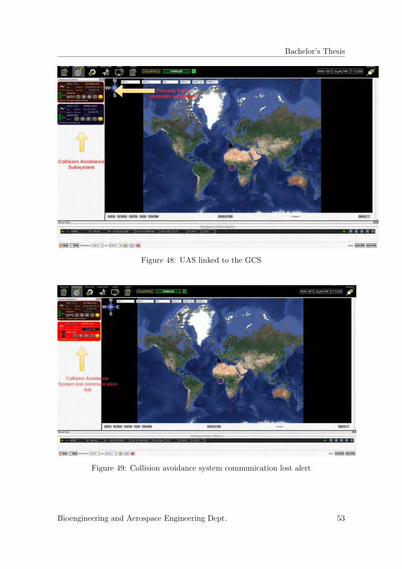
Bachelor’s Thesis
Figure 48: UAS linked to the GCS
Figure 49: Collision avoidance system communication lost alert
Bioengineering and Aerospace Engineering Dept. 53
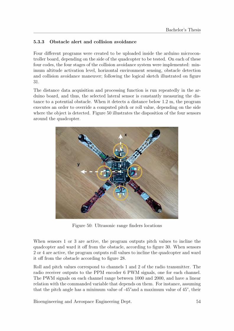
Bachelor’s Thesis
5.3.3 Obstacle alert and collision avoidance
Four different programs were created to be uploaded inside the arduino microcon-troller board, depending on the side of the quadcopter to be tested. On each of thesefour codes, the four stages of the collision avoidance system were implemented: min-imum altitude activation level, horizontal environment sensing, obstacle detectionand collision avoidance maneuver; following the logical sketch illustrated on figure31.
The distance data acquisition and processing function is run repeatedly in the ar-duino board, and thus, the selected lateral sensor is constantly measuring the dis-tance to a potential obstacle. When it detects a distance below 1.2 m, the programexecutes an order to override a computed pitch or roll value, depending on the sidewhere the object is detected. Figure 50 illustrates the disposition of the four sensorsaround the quadcopter.
Figure 50: Ultrasonic range finders locations
When sensors 1 or 3 are active, the program outputs pitch values to incline thequadcopter and ward it off from the obstacle, according to figure 30. When sensors2 or 4 are active, the program outputs roll values to incline the quadcopter and wardit off from the obstacle according to figure 28.
Roll and pitch values correspond to channels 1 and 2 of the radio transmitter. Theradio receiver outputs to the PPM encoder 6 PWM signals, one for each channel.The PWM signals on each channel range between 1000 and 2000, and have a linearrelation with the commanded variable that depends on them. For instance, assumingthat the pitch angle has a minimum value of -45°and a maximum value of 45°, their
Bioengineering and Aerospace Engineering Dept. 54
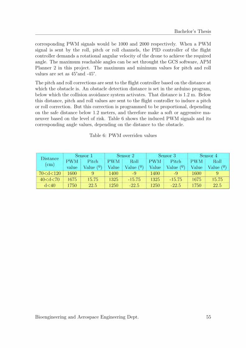
Bachelor’s Thesis
corresponding PWM signals would be 1000 and 2000 respectively. When a PWMsignal is sent by the roll, pitch or roll channels, the PID controller of the flightcontroller demands a rotational angular velocity of the drone to achieve the requiredangle. The maximum reachable angles can be set throught the GCS software, APMPlanner 2 in this project. The maximum and minimum values for pitch and rollvalues are set as 45°and -45°.
The pitch and roll corrections are sent to the flight controller based on the distance atwhich the obstacle is. An obstacle detection distance is set in the arduino program,below which the collision avoidance system activates. That distance is 1.2 m. Belowthis distance, pitch and roll values are sent to the flight controller to induce a pitchor roll correction. But this correction is programmed to be proportional, dependingon the safe distance below 1.2 meters, and therefore make a soft or aggressive ma-neuver based on the level of risk. Table 6 shows the induced PWM signals and itscorresponding angle values, depending on the distance to the obstacle.
Table 6: PWM overriden values
Bioengineering and Aerospace Engineering Dept. 55
Bachelor’s Thesis
6 Testing and Results
This section covers the experimental tests performed to prove the quadcopter flightcapabilities, as well as the collision avoidance system performance.
For the quadcopter, the experimental tests consist basically on flight tests to provethe two utilized flight modes: stabilize and altitude hold.
For the collision avoidance system, a systematic approach is carried out, testingfirstly the components separately, then the communications, and finally the systemimplemented in the MAV, by ground tests and flight tests too.
6.1 Flight capabilities tests and results
As introduced some lines above, the flight capabilities of the F450 quadcopter needto be tested in order to later test the collision avoidance system once implemented.
6.1.1 Stabilize flight mode
As already introduced in section 3.2.2, stabilize mode levels automatically the vehi-cle, based on IMU sensor readings, and the vehicle change its trajectory only underpilot desired inputs of roll, pitch, thrust and yaw.
Once the drone was totally calibrated by following the procedure covered in section5.1, outside flights were carried out, in a private preserve located in Parla.
Initially, the drone’s behavior was pretty worse than expected, since it was not evenable to hover for some seconds.
Figure 51: Video footage frame of stabilize mode test
This issue was solved by checking the PID parameters, which can be adjusted inthe ground control station. The PID controllers are the mechanism employed inside
Bioengineering and Aerospace Engineering Dept. 56

Bachelor’s Thesis
the Pixhawk flight controller to constantly calculate the error value as the differencebetween the desired output variables and the sensor-measured ones. Based on thatdifference, the controllers apply rectifications based on proportional, integral andderivative terms. Figure 52 illustrates the recommended PID parameter values bythe official Ardupilot webpage [41].
Figure 52: PID recommended parameters [41]
Once those values were corrected, the quadcopter flight performance was increasinglyimproved. Several flight tests were performed and recorded, to check its stability.Notice that stability during flight was a major concern to prove in flight the collisionavoidance capabilities. The ultrasonic range finders need a relative stable hover tosend and receive pulses in a proper manner, and output time elapsed data to thearduino microcontroller board.
6.1.2 Altitude hold mode
As already mentioned in section 3.2.2, altitude hold flight mode operates in the sameway as stabilize flight mode for the Euler angles control. The main difference lies onthat throttle is automatically adjusted by the flight controller to maintain a fixedaltitude.
This flight mode was tried and tested in the F450 quadcopter. The main reason washaving an alternative flight mode on which proving the collision avoidance system. Insection 4.2.4, the collision avoidance maneuver stage was explained. A main problemis caused when the vehicle pitches or rolls. The lift force is no longer aligned with thez-axis and the drone falls down. When altitude mode is activated, the drone should
Bioengineering and Aerospace Engineering Dept. 57
Bachelor’s Thesis
maintain its altitude, independently of the commanded pitch or roll maneuvers. Inthat way, the collision avoidance maneuver could be performed at a fixed altitude.
First of all, altitude hold mode was tested without the collision avoidance systemintegrated. Overall, the results were good, in spite of some usual problems.
As mentioned, the drone maintains the altitude based on pressure readings fromthe barometer installed inside the Pixhawk flight controller. This has a major andcommon drawback. When the flight controller is directly exposed to propeller wash,the internal barometer is subjected to pressure changes that confuse the flight con-troller and make it oscillate in a range between one and two meters. This issue couldbe solved by locating the Pixhawk flight controller between the power distributionboard plate and the upper link plate. In that way, the propeller wash effect doesnot affect directly to the flight controller since it would be protected. That solutionwas tried but a new issue appeared. The separation between the upper and bottomplates is not too wide, and therefore, the flight controller was pretty tightly tapped.This caused a major transmission of vibrations to the flight controller during flyingtests. Vibrations in the flight controller are not desirable at all. They cause thedrone to fly with lots of vibration and shaking unpredictable movements,that makeit manually uncontrollable.
A solution to successfully operate altitude hold flight mode in the quadcopter builtthroughout this project is proposed. The flight controller should remain on itscurrent position, in the top of the upper link together with a cushioning sponge toabsorb the vibrations. To wipe out the propeller wash effect, a small case could beprinted to be adapted on the F450 kit. That would solve the propeller wash effectand at the same time would prevent the flight controller from potential collisions,since it would cover it completely. That solution lies on future work to be developedon this quadcopter.
6.2 Component testing and results
The components that lay the obstacle collision avoidance must be initially testedisolated, to check its functionality before integrating them into the rest of the quad-copter.
6.2.1 HC-SR04 Ultrasonic range finders
Five ultrasonic range finders were assembled to the quadcopter. The selected criteriaof the range finders was based mainly on its price. HC-SR04 is the cheapest rangefinder in the market. Notice that one relevant requirement and limitation on thedevelopment of this project lies on the budget.
Firstly, the range finders were separately tested plugged to the Arduino Mega 2560microcontroller board following the wiring sketch illustrated in figure 45. An arduino
Bioengineering and Aerospace Engineering Dept. 58
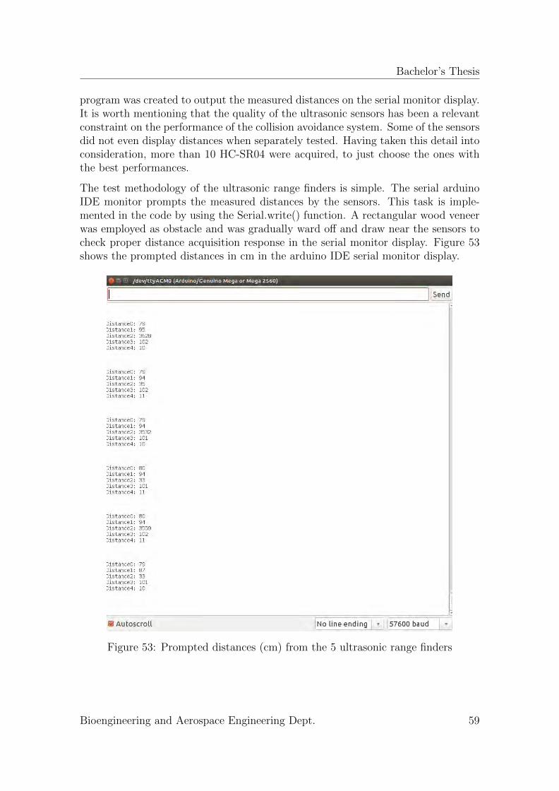
Bachelor’s Thesis
program was created to output the measured distances on the serial monitor display.It is worth mentioning that the quality of the ultrasonic sensors has been a relevantconstraint on the performance of the collision avoidance system. Some of the sensorsdid not even display distances when separately tested. Having taken this detail intoconsideration, more than 10 HC-SR04 were acquired, to just choose the ones withthe best performances.
The test methodology of the ultrasonic range finders is simple. The serial arduinoIDE monitor prompts the measured distances by the sensors. This task is imple-mented in the code by using the Serial.write() function. A rectangular wood veneerwas employed as obstacle and was gradually ward off and draw near the sensors tocheck proper distance acquisition response in the serial monitor display. Figure 53shows the prompted distances in cm in the arduino IDE serial monitor display.
Figure 53: Prompted distances (cm) from the 5 ultrasonic range finders
Bioengineering and Aerospace Engineering Dept. 59

Bachelor’s Thesis
6.2.2 Arduino Mega 2560
Arduino Mega 2560 micro controller board was implemented into the MAV systemfollowing the flight controller wiring scheme illustrated in figure 42. Proper poweringwas checked by repeating the HC-SR04 range finders tests when they were alreadyassembled to the quadcopter. This test was just carried out to ensure proper powersupply to all the collision avoidance system components.
6.3 MAVLink communication testing and results
A program was created to constantly send heartbeat messages from the ArduinoMega 2560 to the Pixhawk flight controller. The utility of this MAVLink messageslies on constantly monitoring the communication between arduino microcontrollerboard and Pixhawk flight controller. To check whether the link is established andthe Arduino Mega 2560 is identified by the ground control station as an additionalUAS system, the UAS systems monitor display in the APM Planner 2 GCS softwareis consulted. In case of proper communication link, the UAS display should remainas illustrated in figure 48.
Some difficulties were faced prior to getting successful communication. To sendthe Heartbeat message, a function called mavlink msg heartbeat pack() must beemployed. That function belongs to mavlink libraries and their inputs are given intable 2. Specially, System ID, Component ID and Message ID inputs are intricateto know. They have a predefined enumeration based on the specific componentsthat form the UAS. That enumeration depends mainly on the hardware componentsbeing used, and sometimes gets tough to know if proper values are being input,specially when no communication seems to be established and nothing alerts aboutthe reason.
6.4 Obstacle collision avoidance ground tests
Some ground tests were performed to prove the effectiveness of the obstacle collisionavoidance system. In that way, flight performance can be estimated and the collisionavoidance system is not proved for the first time on flight tests, which could lead tofailure and dramatic consequences for the physical integrity of the quadcopter.
6.4.1 Arming and disarming test
A sketch program to be run in the arduino board was created to arm and disarm thevehicle each time one of the lateral sensors detect an obstacle below the range of 1.2meters. Based on the processed distance for a selected lateral sensor, the arduino
Bioengineering and Aerospace Engineering Dept. 60
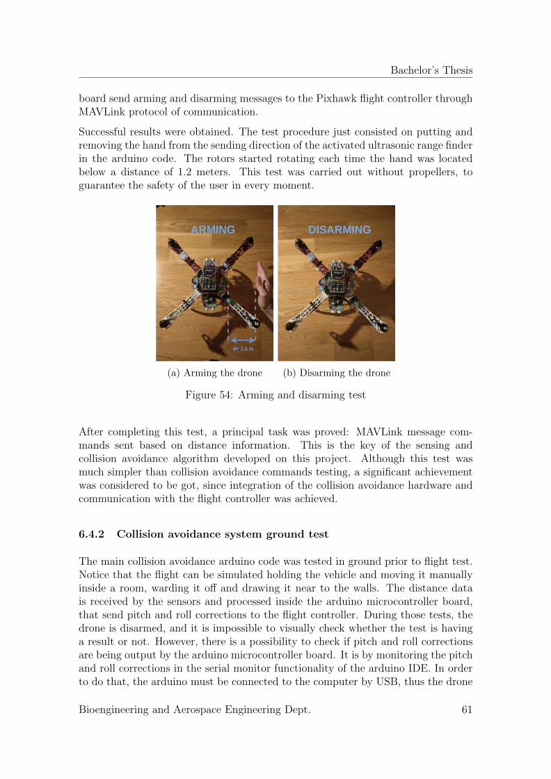
Bachelor’s Thesis
board send arming and disarming messages to the Pixhawk flight controller throughMAVLink protocol of communication.
Successful results were obtained. The test procedure just consisted on putting andremoving the hand from the sending direction of the activated ultrasonic range finderin the arduino code. The rotors started rotating each time the hand was locatedbelow a distance of 1.2 meters. This test was carried out without propellers, toguarantee the safety of the user in every moment.
(a) Arming the drone (b) Disarming the drone
Figure 54: Arming and disarming test
After completing this test, a principal task was proved: MAVLink message com-mands sent based on distance information. This is the key of the sensing andcollision avoidance algorithm developed on this project. Although this test wasmuch simpler than collision avoidance commands testing, a significant achievementwas considered to be got, since integration of the collision avoidance hardware andcommunication with the flight controller was achieved.
6.4.2 Collision avoidance system ground test
The main collision avoidance arduino code was tested in ground prior to flight test.Notice that the flight can be simulated holding the vehicle and moving it manuallyinside a room, warding it off and drawing it near to the walls. The distance datais received by the sensors and processed inside the arduino microcontroller board,that send pitch and roll corrections to the flight controller. During those tests, thedrone is disarmed, and it is impossible to visually check whether the test is havinga result or not. However, there is a possibility to check if pitch and roll correctionsare being output by the arduino microcontroller board. It is by monitoring the pitchand roll corrections in the serial monitor functionality of the arduino IDE. In orderto do that, the arduino must be connected to the computer by USB, thus the drone
Bioengineering and Aerospace Engineering Dept. 61
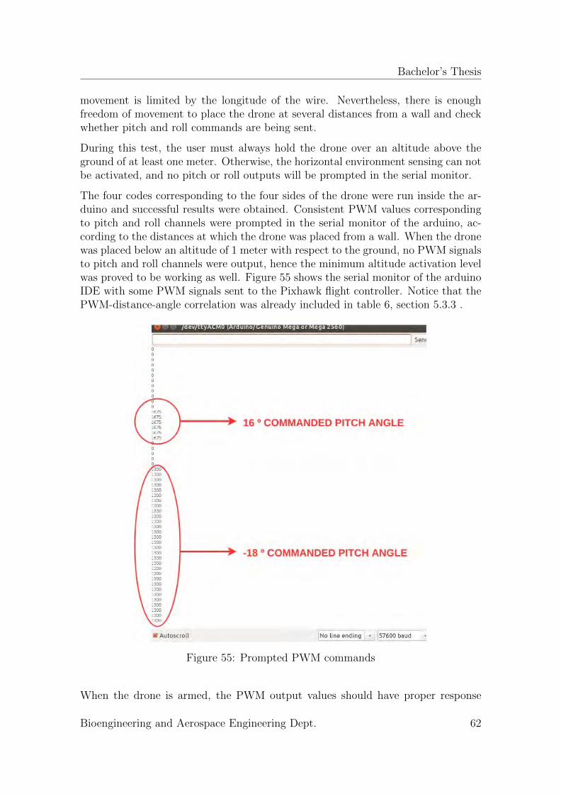
Bachelor’s Thesis
movement is limited by the longitude of the wire. Nevertheless, there is enoughfreedom of movement to place the drone at several distances from a wall and checkwhether pitch and roll commands are being sent.
During this test, the user must always hold the drone over an altitude above theground of at least one meter. Otherwise, the horizontal environment sensing can notbe activated, and no pitch or roll outputs will be prompted in the serial monitor.
The four codes corresponding to the four sides of the drone were run inside the ar-duino and successful results were obtained. Consistent PWM values correspondingto pitch and roll channels were prompted in the serial monitor of the arduino, ac-cording to the distances at which the drone was placed from a wall. When the dronewas placed below an altitude of 1 meter with respect to the ground, no PWM signalsto pitch and roll channels were output, hence the minimum altitude activation levelwas proved to be working as well. Figure 55 shows the serial monitor of the arduinoIDE with some PWM signals sent to the Pixhawk flight controller. Notice that thePWM-distance-angle correlation was already included in table 6, section 5.3.3 .
Figure 55: Prompted PWM commands
When the drone is armed, the PWM output values should have proper response
Bioengineering and Aerospace Engineering Dept. 62
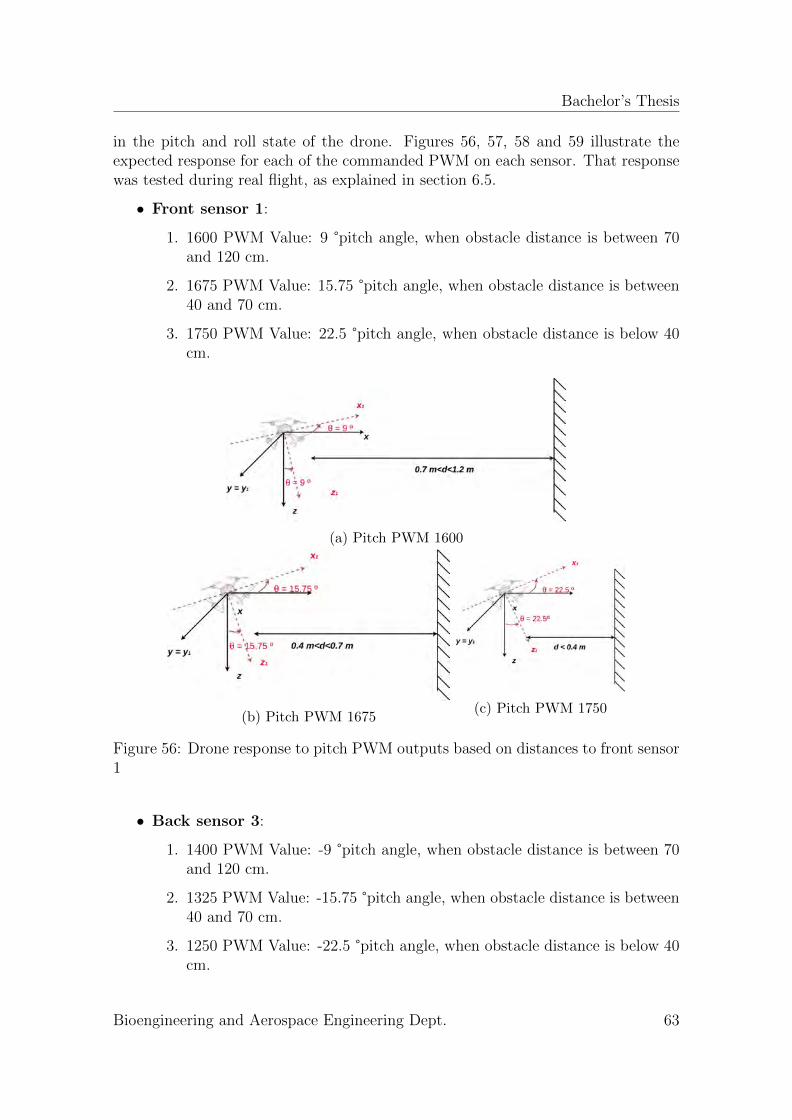
Bachelor’s Thesis
in the pitch and roll state of the drone. Figures 56, 57, 58 and 59 illustrate theexpected response for each of the commanded PWM on each sensor. That responsewas tested during real flight, as explained in section 6.5.
• Front sensor 1:
1. 1600 PWM Value: 9 °pitch angle, when obstacle distance is between 70and 120 cm.
2. 1675 PWM Value: 15.75 °pitch angle, when obstacle distance is between40 and 70 cm.
3. 1750 PWM Value: 22.5 °pitch angle, when obstacle distance is below 40cm.
(a) Pitch PWM 1600
(b) Pitch PWM 1675(c) Pitch PWM 1750
Figure 56: Drone response to pitch PWM outputs based on distances to front sensor1
• Back sensor 3:
1. 1400 PWM Value: -9 °pitch angle, when obstacle distance is between 70and 120 cm.
2. 1325 PWM Value: -15.75 °pitch angle, when obstacle distance is between40 and 70 cm.
3. 1250 PWM Value: -22.5 °pitch angle, when obstacle distance is below 40cm.
Bioengineering and Aerospace Engineering Dept. 63
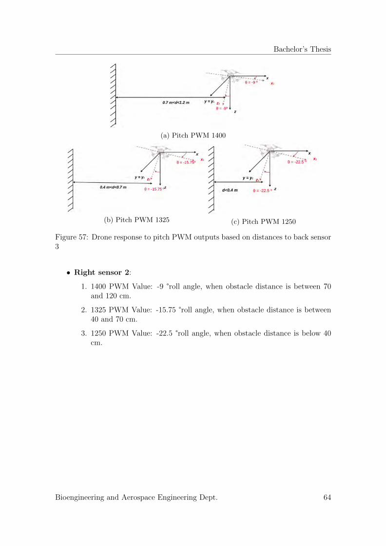
Bachelor’s Thesis
(a) Pitch PWM 1400
(b) Pitch PWM 1325 (c) Pitch PWM 1250
Figure 57: Drone response to pitch PWM outputs based on distances to back sensor3
• Right sensor 2:
1. 1400 PWM Value: -9 °roll angle, when obstacle distance is between 70and 120 cm.
2. 1325 PWM Value: -15.75 °roll angle, when obstacle distance is between40 and 70 cm.
3. 1250 PWM Value: -22.5 °roll angle, when obstacle distance is below 40cm.
Bioengineering and Aerospace Engineering Dept. 64
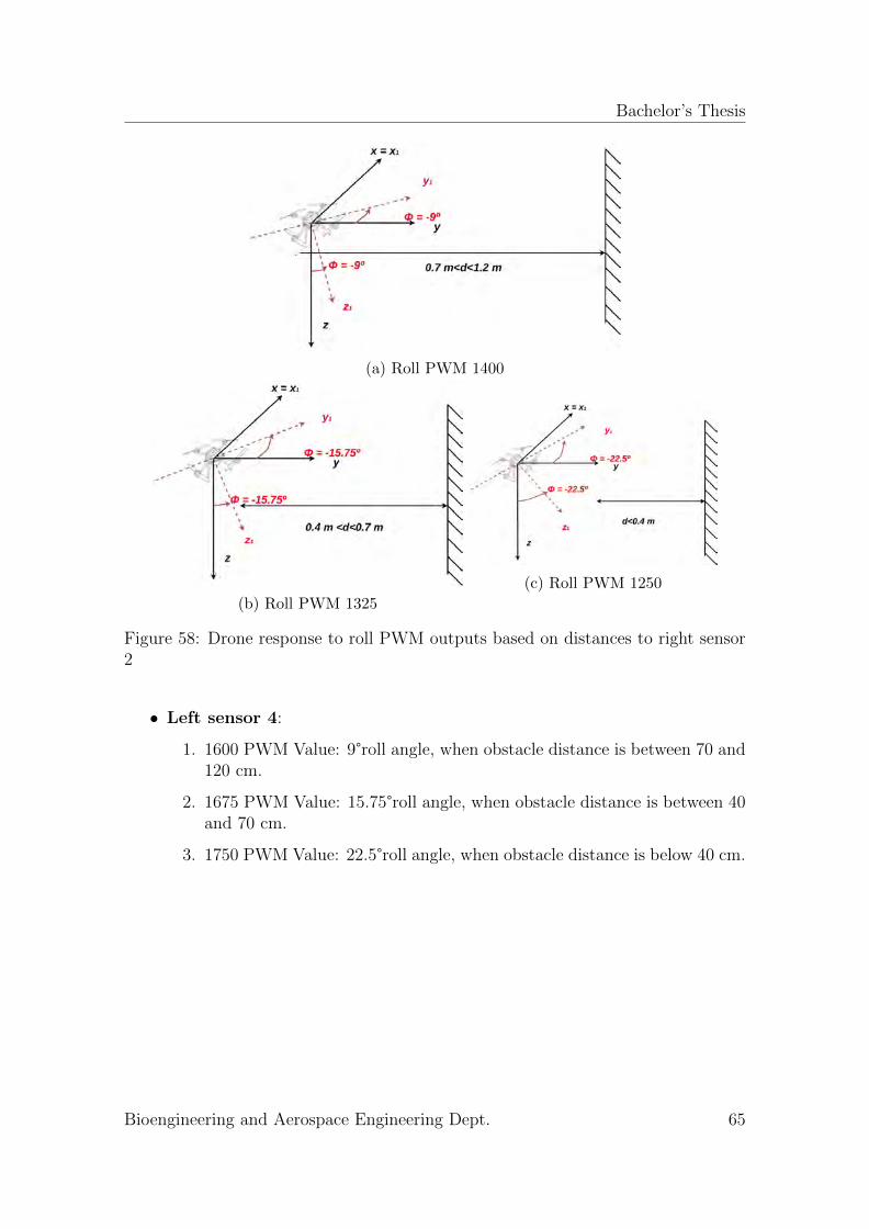
Bachelor’s Thesis
(a) Roll PWM 1400
(b) Roll PWM 1325
(c) Roll PWM 1250
Figure 58: Drone response to roll PWM outputs based on distances to right sensor2
• Left sensor 4:
1. 1600 PWM Value: 9°roll angle, when obstacle distance is between 70 and120 cm.
2. 1675 PWM Value: 15.75°roll angle, when obstacle distance is between 40and 70 cm.
3. 1750 PWM Value: 22.5°roll angle, when obstacle distance is below 40 cm.
Bioengineering and Aerospace Engineering Dept. 65
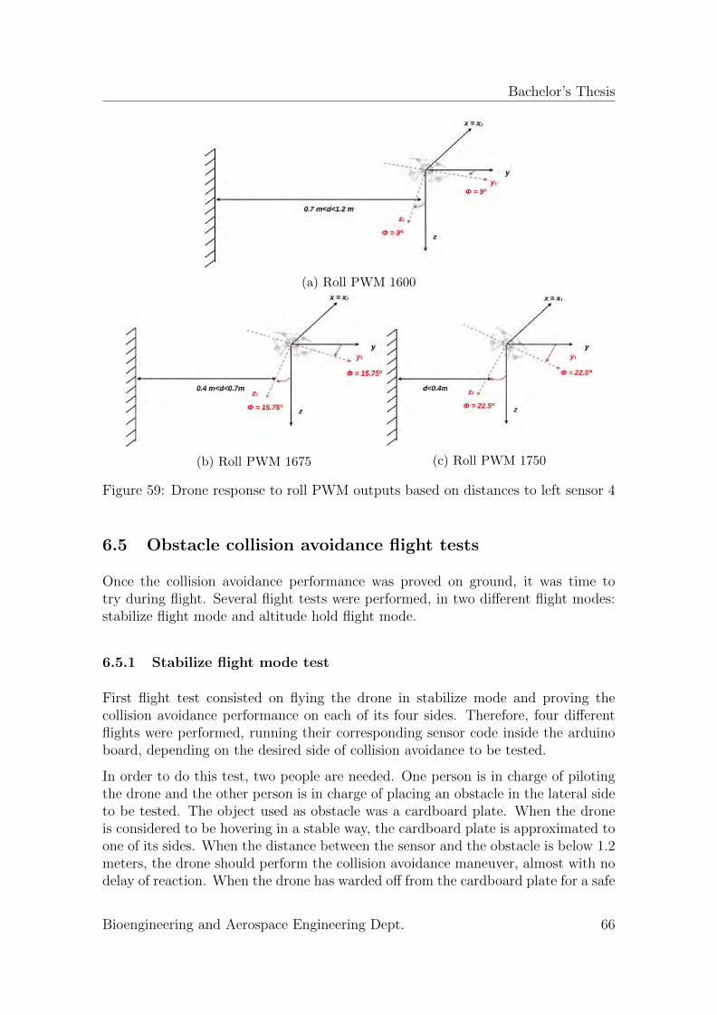
Bachelor’s Thesis
(a) Roll PWM 1600
(b) Roll PWM 1675 (c) Roll PWM 1750
Figure 59: Drone response to roll PWM outputs based on distances to left sensor 4
6.5 Obstacle collision avoidance flight tests
Once the collision avoidance performance was proved on ground, it was time totry during flight. Several flight tests were performed, in two different flight modes:stabilize flight mode and altitude hold flight mode.
6.5.1 Stabilize flight mode test
First flight test consisted on flying the drone in stabilize mode and proving thecollision avoidance performance on each of its four sides. Therefore, four differentflights were performed, running their corresponding sensor code inside the arduinoboard, depending on the desired side of collision avoidance to be tested.
In order to do this test, two people are needed. One person is in charge of pilotingthe drone and the other person is in charge of placing an obstacle in the lateral sideto be tested. The object used as obstacle was a cardboard plate. When the droneis considered to be hovering in a stable way, the cardboard plate is approximated toone of its sides. When the distance between the sensor and the obstacle is below 1.2meters, the drone should perform the collision avoidance maneuver, almost with nodelay of reaction. When the drone has warded off from the cardboard plate for a safe
Bioengineering and Aerospace Engineering Dept. 66
Bachelor’s Thesis
distance higher than 1.2 meter, the drone should stabilize again and the pitch/rollcontrol should return back to the pilot.
Results obtained during this flight test had a major issue. The collision avoidanceactuated and the drone warded off from the obstacles. However, after performingthe collision avoidance, sometimes, the drone fell to the ground with almost no timeof reaction for the pilot to adjust the throttle and maintain an stable hover.
The collision avoidance concept proof was achieved, but stability after avoidancemaneuver was a relevant issue to be solved in order to fulfill the initial requirementsestablished for the object collision avoidance system.
6.5.2 Altitude hold flight mode test
To solve the stability issue of the drone after collision avoidance, altitude hold flightmode tests were done. That could prevent the drone from falling to the ground byfixing an altitude to hover during the test.
Same tests as in stabilize mode were performed: one flight for each of the four lateralsides to be proved.
Results were apparently good. The drone did not fall to the ground after avoiding thecollision against the obstacle, since a fixed altitude was commanded to be maintainedbased on pressure readings from the barometer inside the flight controller. Thedrone performed the collision avoidance maneuver in the four sides letting the pilotcontinue with a stable hover once the obstacle was out of the margin distance of 1.2meters.
There was only one issue regarding to this flight mode. The quadcopter tends tooscillate in a range of 1 to 2 meters when flying in altitude hold mode. The altitudeshould be completely fixed, but propeller’s wash effect changes the pressure readingof the barometer that gets confused and believes that the quadcopter is changing itsaltitude. A solution as a future work is proposed, and lies on covering and protectingthe Pixhawk flight controller with a case.
Bioengineering and Aerospace Engineering Dept. 67
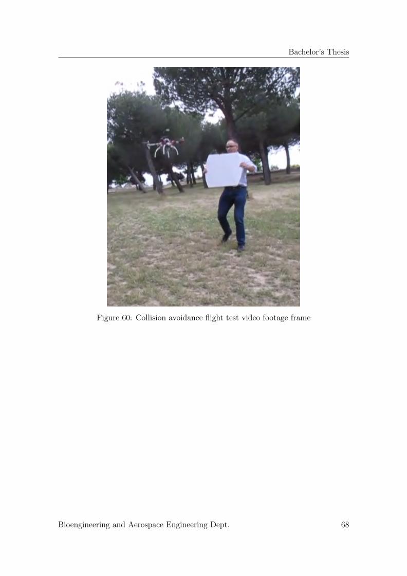
Bachelor’s Thesis
Figure 60: Collision avoidance flight test video footage frame
Bioengineering and Aerospace Engineering Dept. 68
Bachelor’s Thesis
7 Summary, Conclusions and Future work
During this project, a preliminary design of a collision avoidance system for un-manned aerial vehicles with Pixhawk flight controller has been developed, imple-mented into a real quadcopter, and tested in realistic scenarios. Five ultrasonicrange finder sensors were integrated into a F450 quadcopter, with the purpose ofmonitoring the horizontal environment an avoiding potential collisions with objectsplaced on its surroundings.
7.1 Project summary
The most significant objective of the project lied on the design and integrationof the collision avoidance functionality as an additional subsystem to improve thesafety in flight operations of unmanned aerial vehicles equipped with Pixhawk flightcontroller. This task implied the use of many hardware components and software ele-ments in order to have a complete and reliable system to satisfy the initial objectivespretended to be fulfilled.
A set of requirements were established as target functionality, integration, perfor-mance, usability, interface, operational, states, physical, design, certification andcost preliminary conditions that orientated the development of the collision avoid-ance subsystem from hardware and software selection to the design and integrationphases.
A collision avoidance algorithm was designed to follow four well differentiated stagesfrom stable hover state to successful collision elusion. Firstly, a minimum altitudeactivation layer was introduced into the solution, consisting on constant monitoringof the altitude until a minimum height of 1 meter is reached and the subsequenthorizontal environment monitoring stage starts. During the horizontal environmentmonitoring stage, the ultrasonic range finder sensors located in the four lateral sidesof the quadcopter trigger constantly ultrasonic waves in order to obtain raw distanceinformation of the objects placed around the vehicle. That raw data is processed inan auxiliary arduino microcontroller board. Next stage is the obstacle detection, andoccurs when an processed distance is lower than a safe margin of 1.2 meters. Laststage is the collision avoidance maneuver and proceeds the obstacle detection stagewith negligible margin of delay. When a distance is sensed to be under 1.2 meters,the arduino auxiliary board triggers pitch and roll corrections to the Pixhawk flightcontroller through MAVLink protocol of communication. Those corrections makethe quadcopter ward off from the potential risky obstacle. Once the distance to theobject is over 1.2 meters, the control of the pitch/roll angles of the vehicle returnsto the pilot.
To implement the collision avoidance subsystem, it was firstly necessary to havea testing quadcopter. Therefore, a F450 flight capable quadcopter was built from
Bioengineering and Aerospace Engineering Dept. 69
Bachelor’s Thesis
scratch and calibrated, achieving proper flight performances with stable hover capa-bilities. Afterwards, the collision avoidance subsystem integration was carried out,firstly by hardware implementation of the components and later by software inte-gration; achieving proper communications among all the subsystems of the droneand specially, between the arduino microcontroller board and the Pixhawk flightcontroller. Arduino programs were developed to process the distance acquired bythe ultrasonic range finder sensors and based on them; send trajectory correctionsto the Pixhawk flight controller.
The testing phase was carried out following a systematic approach. Initially, thequadcopter testing platform was tested without the collision avoidance system im-plemented. Several flights were performed to prove its proper flight capabilities.Subsequently, the ultrasonic range finder sensors were tested connected to the ar-duino microcontroller board as an isolated system in order to check proper distancemeasurements. After that, the collision avoidance was tested being implemented intothe quadcopter by ground tests. Successful trajectory corrections commands wheremonitored by the arduino IDE monitor display, and acceptable results were obtainedto proceed to the final and main test phase: flight tests. The flight tests with thecollision avoidance system integrated where carried out in outside environment sce-nario. Obstacles where simulated by an auxiliary person holding a cardboard plateand placing it in front of the lateral sides of the drone. Acceptable results wereobtained to verify that the proof of concept of the collision avoidance system wasworking. The drone responded warding off from the obstacles and performing thepitch and roll correction maneuvers, in spite of some stability difficulties when re-turning the control to the pilot and ultrasonic range finder quality limitations thatmake some attempts not to succeed.
7.2 Extracted conclusions
Overall, the following isolated conclusions can be extracted:
• Current state of the art and the existing technology resources makes the col-lision avoidance being an implementable technology that can be integratedinto unmanned aerial vehicles. Programming skills are needed to implementthe avoidance algorithm, but in this project it has been demonstrated thatbasic aptitudes on arduino programming language are enough to test a proofof concept of collision avoidance.
• MAVLink protocol of communication is a huge and useful tool to implementany kind of capability to drones, prior compatibility of hardware components.Useful functionalities can be implemented to improve performance of dronesin applications such as search an rescue, inspections and security.
• Hardware capabilities can seriously limit the performance of unmanned aerialvehicle systems. In this project, the HC-SR04 ultrasonic range finder sensors
Bioengineering and Aerospace Engineering Dept. 70
Bachelor’s Thesis
were selected due to its cheap price. They had significant limitations in termsof precision in the measurements that make some flight tests not to suceed.
• Communications among subsystems is a tough and critical task for the properdevelopment of capabilities in unmanned aerial vehicle systems. In this project,MAVLink communication between the arduino microcontroller board and thePixhawk flight controller became difficult. MAVLink is a protocol of commu-nication with the purpose of information exchange between unmanned aerialvehicle systems, which is constantly being updated and the libraries on whichit is based are constantly being developed by users. However, there are notmany teaching resources available to acquire a basis from which start develop-ing. Further advances need to be done in this aspect.
• Hardware compatibility is also a critical aspect that needs to be checked priorto hardware selection for unmanned aerial vehicles. In this project, the com-patibility of communications between the arduino microcontroller, the ultra-sonic range finder sensors and the Pixhawk flight controller was checked priorto start working on it.
• Systematic approach in the test phase is necessary in order to achieve results.Specially for drones, where failures could deteriorate the physical integrity ofa testing platform, it is very important to perform ground-based tests with theaim to ensure that communications and subsystems integration are ready.
• Overall, during this project, a baseline of work was established on which de-veloping further improvements and ideas with the aim to get a more reliableand safe collision avoidance system.
7.3 Future work
During the development of this project, only a proof of concept of a preliminarycollision avoidance system was tested. There are still many software and hardwarerelated improvements and ideas that could be implemented. Some of them are heredelineated:
• Two flight modes were proved during this project: stabilize flight mode andaltitude hold flight mode. Altitude flight mode would be a much more efficientmode on which testing the collision avoidance system, since fixing an altitudeprevents the drone from falling to the ground when pitch and roll correctionsare overwritten. In the test phase, altitude hold flight mode gave a relevantissue. Propeller wash effect confused the pressure readings of the flight con-troller barometer, making it oscillate within a range between 1 and 2 meters.A further solution would lie on printing a case to cover the flight controllerand protect it from this effect.
• The collision avoidance algorithm was just developed to be tested on one lat-
Bioengineering and Aerospace Engineering Dept. 71
Bachelor’s Thesis
eral side on each flight test. Further arduino programming development couldlet proving flight tests with the four lateral sensors working at the same time.In that way, more than one obstacle could be placed and more complex trajec-tory corrections would need to be developed. By doing this, a 360°horizontalcollision avoidance poof of concept would be achieved.
• The ultrasonic range finders can be assembled to the plates of the drone in amore efficient way. They are basically taped with elastic bands. This causedundesirable vibrations during flight that could lead to failure in distance read-ings.
• Hardware improvements could be implemented into the system. Higher perfor-mance ultrasonic range finder sensors acquisition would lead to more successfulcollision avoidance performances.
• The collision avoidance maneuver stage could be further improved. More pre-cise angle computations could be done, based on the distance to obstacles.With the current avoidance maneuver arduino program, the drone usuallyresponses with very aggressive pitch/roll maneuvers that make the vehicledestabilize and sometimes fall to the ground. Softer pitch/roll correctionswould maintain the drone on its hovering position, making the control-returnto the pilot a feasible task.
Bioengineering and Aerospace Engineering Dept. 72
Bachelor’s Thesis
References
[1] Andrew R Lacher, David R Maroney, Andrew D Zeitlin, et al. “Unmannedaircraft collision avoidance–technology assessment and evaluation methods”.In: FAA EUROCONTROL ATM R&D Symposium, Barcelona, Spain. 2007.
[2] Javier Lloret. Introduction to Air Navigation. Create Space, 2016.[3] Bijan V Darryl J. “The economic impact of unmanned aircraft systems inte-
gration in the USA”. In: 2013.[4] Dane Bamburry. “Drones: Designed for product delivery”. In: Design Manage-
ment Review 26.1 (2015), pp. 40–48.[5] Real Decreto 1036/2017. Ministerio de la presidencia y para las administra-
ciones territoriales, Dec. 2017.[6] Salario: Ingeniero Junior en Espana. url: http://espana.jobtonic.es/
salary/26526/74925.html (visited on 06/02/2018).[7] Unmanned Aircraft Systems. International Civil Aviation Organization, Feb.
2016.[8] M Hassanalian and A Abdelkefi. “Classifications, applications, and design chal-
lenges of drones: a review”. In: Progress in Aerospace Sciences 91 (2017),pp. 99–131.
[9] Gonzalo Pajares. “Overview and current status of remote sensing applicationsbased on unmanned aerial vehicles (UAVs)”. In: Photogrammetric Engineering& Remote Sensing 81.4 (2015), pp. 281–329.
[10] How does LiDAR work? The science behind the technology. url: http://www.lidar-uk.com/how-lidar-works/ (visited on 06/03/2018).
[11] HDL-32E lidar. url: http://velodynelidar.com/hdl-32e.html (visited on03/02/2018).
[12] LeddarOne Single-Element Sensor Module. url: https://leddartech.com/modules/leddarone/ (visited on 03/02/2018).
[13] Sonar working principle. url: https://www.zigya.com/study/book?class=9 & board = cbse & subject = science & book = science & chapter = sound & q _
type = &q _ topic = &q _ category = &question _ id = SCEN9016176 (visited on04/02/2018).
[14] MB1010 LV-MaxSonar-EZ1. url: https://www.maxbotix.com/Ultrasonic_Sensors/MB1010.htm (visited on 03/02/2018).
[15] Samuel S Blackman. “Multiple-target tracking with radar applications”. In:Dedham, MA, Artech House, Inc., 1986, 463 p. (1986).
[16] PRINCIPALES APLICACIONES DE SISTEMAS DE RADAR. url: http://elradar.50webs.com/aplicaciones.htm (visited on 02/03/2018).
[17] Copter Object Avoidance. url: http://ardupilot.org/dev/docs/code-overview-object-avoidance.html (visited on 02/03/2018).
[18] LightWare SF40/C 100m Laser Scanner 360 SLAM. url: https://www.
3dxr . co . uk / product / lightware - sf40c - laser - scanner/ (visited on02/03/2018).
Bioengineering and Aerospace Engineering Dept. 73
Bachelor’s Thesis
[19] TeraRanger Tower. url: http://www.teraranger.com/product/teraranger-tower/ (visited on 02/03/2018).
[20] Frame Class Configuration. url: http://ardupilot.org/copter/docs/
frame-type-configuration.html (visited on 02/04/2018).[21] BLDC motor basics. url: https://www.renesas.com/en- eu/support/
technical - resources / engineer - school / brushless - dc - motor - 01 -
overview.html (visited on 03/04/2018).[22] Constant Speed Propellers. url: http://www.dauntless-soft.com/PRODUCTS/
Freebies/Library/books/FLT/Chapter2/Constant.htm (visited on 04/04/2018).[23] Helice Gemfan fibra de carbono 10x4.5 (pareja) Estilo APC SF. url: http:
//www.dauntless-soft.com/PRODUCTS/Freebies/Library/books/FLT/
Chapter2 / Constant . htmhttps : / / rc - innovations . es / Helices - de -
carbono-aviones-rc-drones-gemfan/helice-fibra-carbono-10x4.5-
pareja-multicoptero (visited on 05/05/2018).[24] Pulse Width Modulation with analog write. url: http://robotic-controls.
com/book/export/html/57 (visited on 06/04/2018).[25] Desire power V8 Series 3s 4000mAh 30C. url: https://rc-innovations.
es/Baterias-lipo-3s-calidad-drones/desire-power-3s-4000-30c-
bateria-lipo7 (visited on 03/23/2018).[26] Pixhawk Overview. url: https://pixhawk.org/ (visited on 04/21/2018).[27] Pixhawk clones good/bad. url: https://discuss.ardupilot.org/t/pixhawk-
clones-good-bad/9552 (visited on 06/10/2018).[28] Pixhawk clones good/bad. url: https://whatis.techtarget.com/definition/
firmware (visited on 05/03/2018).[29] Arduino. url: https : / / en . wikipedia . org / wiki / Arduino (visited on
04/06/2018).[30] Arduino Mega 2560 REV3. url: https://store.arduino.cc/usa/arduino-
mega-2560-rev3 (visited on 03/05/2018).[31] Telemetry Radio. url: http://ardupilot.org/copter/docs/common-sik-
telemetry-radio.html (visited on 02/22/2018).[32] Flysky FS-i6 AFHDS. url: https://www.tomtop.com (visited on 04/03/2018).[33] HCSR04. url: http://www.cordobatec.com/producto/sensor-ultrasonico-
hc-sr04/ (visited on 04/05/2018).[34] Arduino IDE interface. url: https://www.pololu.com/docs/0J61/6.2
(visited on 03/04/2018).[35] Flight Modes. url: http://ardupilot.org/copter/docs/flight-modes.
html (visited on 03/06/2018).[36] Stabilize Mode. url: http://ardupilot.org/copter/docs/stabilize-
mode.html (visited on 02/05/2018).[37] RC Hardware What is an RC transmitter? url: https://www.pololu.com/
docs/0J61/6.2 (visited on 04/05/2018).[38] Ernesto Santana. MAVLink: Protocolo de comunicacion para drones. url:
http://www.xdrones.es/mavlink/ (visited on 02/02/2018).
Bioengineering and Aerospace Engineering Dept. 74
Bachelor’s Thesis
[39] System Requirements. url: http://www.sebokwiki.org/wiki/System_
Requirements (visited on 04/04/2018).[40] David Morante Manuel Soler Xin Chen Gonzalo Sanchez. Quadcopter assembly
laboratory. University Carlos III of Madrid. 2016.[41] Advanced Tuning. url: http://ardupilot.org/copter/docs/tuning.html
(visited on 02/06/2018).
Bioengineering and Aerospace Engineering Dept. 75