Observations and modeling of debris and shrapnel impacts ... · Observations and modeling of debris...
4
Observations and modeling of debris and shrapnel impacts on optics and diagnostics at the National Ignition Facility D. Eder 1,a , D. Bailey 1 , F. Chambers 1 , I. Darnell 1 , P. Di Nicola 1 , S. Dixit 1 , A. Fisher 1 , G.Gururangan 1 , D. Kalantar 1 , A. Koniges 2 , W. Liu 2 , M. Marinak 1 , N. Masters 1 , V. Mlaker 1 , R. Prasad 1 , S. Sepke 1 , and P. Whitman 1 1 Lawrence Livermore National Laboratory, Livermore, CA, USA 2 Lawrence Berkeley National Laboratory, Berkeley, CA, USA Abstract. A wide range of targets with laser energies spanning two orders of magnitude have been shot at the National Ignition Facility (NIF). The National Ignition Campaign (NIC) targets are cryogenic with Si supports and cooling rings attached to an Al Thermo-Mechanical Package (TMP) with a thin (30 micron) Au hohlraum inside. Particular attention is placed on the low-energy shots where the TMP is not completely vaporized. In addition to NIC targets, a range of other targets has also been fielded on NIF. For all targets, simulations play a critical role in determining if the risks associated with debris and shrapnel are acceptable. In a number of cases, experiments were redesigned, based on simulations, to reduce risks or to obtain data. The majority of these simulations were done using the ALE-AMR code, which provides efficient late-time (100 – 1000X the pulse duration) 3D calculations of complex NIF targets. 1. Introduction The National Ignition Facility (NIF) has a large number of optics and diagnostics that can be impacted by debris and shrapnel. A formal review process of evaluating risks associated with debris and shrapnel is in place and has been used for all NIF shots. A critical component of the review process is simulation of targets and surrounding chamber components to determine the quantity and properties of all debris and shrapnel generated by the proposed shot. The majority of these simulations have been done using the ALE-AMR code, which combines Arbitrary-Lagrangian- Eulerian (ALE) hydrodynamics with Adaptive Mesh Refinement (AMR) [1]. Observations of impacts of debris and shrapnel are also a critical component of the review process. With respect to impacts to optics, one objective is to determine the risk to the 3-mm thick Disposable Debris Shields (DDS’s), which are the optics closest to target center. It is important to avoid penetrations of these DDS’s by shrapnel fragments as well as control the amount of debris deposited, which reduces transmission. Penetrations and craters on DDS’s are observed using a Final Optics Damage Inspection (FODI) system. The number of optics inspected and the frequency of inspections depend on the calculated risks associated with a given shot. Observations of large craters indicate a higher risk of the potential penetrations in subsequent similar shots. a Email : [email protected]
Transcript of Observations and modeling of debris and shrapnel impacts ... · Observations and modeling of debris...
Observations and modeling of debris and shrapnel impacts on optics and diagnostics at the National Ignition Facility
D. Eder1,a
, D. Bailey1, F. Chambers
1, I. Darnell
1, P. Di Nicola
1, S. Dixit
1, A. Fisher
1, G.Gururangan
1,
D. Kalantar1, A. Koniges
2, W. Liu
2, M. Marinak
1, N. Masters
1, V. Mlaker
1, R. Prasad
1, S. Sepke
1,
and P. Whitman1
1Lawrence Livermore National Laboratory, Livermore, CA, USA
2Lawrence Berkeley National Laboratory, Berkeley, CA, USA
Abstract. A wide range of targets with laser energies spanning two orders of
magnitude have been shot at the National Ignition Facility (NIF). The National Ignition
Campaign (NIC) targets are cryogenic with Si supports and cooling rings attached to an
Al Thermo-Mechanical Package (TMP) with a thin (30 micron) Au hohlraum inside.
Particular attention is placed on the low-energy shots where the TMP is not completely
vaporized. In addition to NIC targets, a range of other targets has also been fielded on
NIF. For all targets, simulations play a critical role in determining if the risks associated
with debris and shrapnel are acceptable. In a number of cases, experiments were
redesigned, based on simulations, to reduce risks or to obtain data. The majority of these
simulations were done using the ALE-AMR code, which provides efficient late-time
(100 – 1000X the pulse duration) 3D calculations of complex NIF targets.
1. Introduction
The National Ignition Facility (NIF) has a large number of optics and diagnostics that can be
impacted by debris and shrapnel. A formal review process of evaluating risks associated with debris
and shrapnel is in place and has been used for all NIF shots. A critical component of the review
process is simulation of targets and surrounding chamber components to determine the quantity and
properties of all debris and shrapnel generated by the proposed shot. The majority of these
simulations have been done using the ALE-AMR code, which combines Arbitrary-Lagrangian-
Eulerian (ALE) hydrodynamics with Adaptive Mesh Refinement (AMR) [1]. Observations of
impacts of debris and shrapnel are also a critical component of the review process. With respect to
impacts to optics, one objective is to determine the risk to the 3-mm thick Disposable Debris Shields
(DDS’s), which are the optics closest to target center. It is important to avoid penetrations of these
DDS’s by shrapnel fragments as well as control the amount of debris deposited, which reduces
transmission. Penetrations and craters on DDS’s are observed using a Final Optics Damage
Inspection (FODI) system. The number of optics inspected and the frequency of inspections depend
on the calculated risks associated with a given shot. Observations of large craters indicate a higher
risk of the potential penetrations in subsequent similar shots.
a Email : [email protected]
EPJ Web of Conferences
Assessments of impacts/risks to diagnostics benefit from the ability to do a “debris test” prior to
fielding a diagnostic for a target/laser configuration. In many cases, useful data can be obtained
during a debris-test shot from other diagnostics or the use of a damage tolerant device, e.g., image
plate, in place of the potential new device, e.g., MCP-CCD (Multi-Channel Plate - Charge Coupled
Device), which cannot tolerate shrapnel impacts. Inspection of filters, pinholes, and collimators
between the target and the device is required to determine if a diagnostic passes the debris test.
The National Ignition Campaign (NIC) has a wide range of sub-campaigns to optimize target and
laser parameters to obtain fusion in the laboratory. A drawing of one NIC target is given in the
upper left image in Figure 1. (The thin waffled Al layer on the Si is not shown.) The major change
between the sub-campaigns is the type of capsule that is inside and the laser parameters. In this
paper, we focus on the re-emit campaign that requires less than 1% of NIF’s available energy. For
this campaign, a high-Z Bi capsule is used and the symmetry of x-ray loading at the beginning of the
ignition pulse is measured by imaging the x-rays re-emitted by this capsule.
A wide range of other campaigns have also obtained exciting data on NIF. In this paper, we give
an example where modifications of the experiment based on simulations allowed data to be obtained.
2. NIC targets and associated impacts
In order to calculate shrapnel fragments it is critical to do 3D simulations. However, one tries to
exploit as much symmetry as possible. For the NIC re-emit target, we use a wedge (22.5 degree) of
½ of the target. This means we are simulating 1/32 of the entire target but the simulation includes
the Si and Al target components not included in other ICF simulations. (Other NIC simulations
model ¼ of the target.) The target from an ALE-AMR simulation is shown on the lower left image
of Figure 1 with domain boundaries not displayed. We use an advanced multi-material interface
reconstruction method coupled with AMR to allow accurate modeling of complex structures.
To calculate the late-time dynamics of the re-emit target, we impulsively deposit 14 kJ in the Au
hohlraum liner: expanding the inner 10 um of the hohlraum material such that the inner face is offset
60 microns and the density and internal energy within the expanded region set to uniformly
distribute the associated mass and deposited energy. These simulations were exclusively
hydrodynamic, neglecting radiative and thermal heat transfer effects. The thin-walled Bi capsule is
not included in the simulation but its impact on late-time dynamics is expected to be small. The
simulation at 750 ns is shown on the lower right image in Figure 1. Temperature contours for all
material with density greater than 0.5 g/cm3 are shown. Approximately 2/3 of the target is not
vaporized at this late time. The remaining solid and molten material is a potential risk to diagnostics
and optics. The optics closest to the target are the DDS’s, located approximately 7 m away. The
laser passes through these DDS’s at angles of 23.5, 30.0, 44.5, and 50 degrees as measured from the
poles. To be conservative, we consider all material directed towards those angles plus and minus an
additional 10 degrees. Based on mass and velocity of fragments/droplets, we calculate the risk of
DDS penetration. If a region of solid is calculated to have failed because of stress loading, we bound
the mass by the mass in each zone. For un-failed solid material, we use the calculated mass and
velocity of the entire fragment. For molten material, we use a very conservative upper bound for
mass corresponding to droplets 300 microns in diameter, which is the average thickness of the TMP.
(We are developing and testing surface tension models for ALE-AMR that will enable the
calculation of droplet sizes.) The fragment/droplet predicted by this analysis to have the greatest
penetration capability is a solid fragment with a mass of 0.08 mg and a velocity of 1.5 km/s. Such a
fragment is calculated to not penetrate the 3-mm thick DDS’s [2]. (It is calculated to penetrate a 1-
mm thick DDS.) Inspection of DDS’s by FODI following re-emit shots found no evidence of
penetrations, which is consistent with the simulations and analysis.
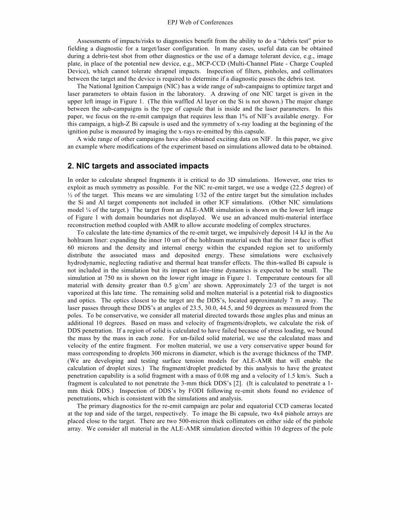
The primary diagnostics for the re-emit campaign are polar and equatorial CCD cameras located
at the top and side of the target, respectively. To image the Bi capsule, two 4x4 pinhole arrays are
placed close to the target. There are two 500-micron thick collimators on either side of the pinhole
array. We consider all material in the ALE-AMR simulation directed within 10 degrees of the pole

Inertial Fusion Sciences and Applications 2011
and waist. For the polar instrument, the fragment/droplet with greatest penetration capability is a
solid fragment with a mass of 0.08 mg and a velocity of 3 km/s. This fragment is calculated to not
penetrate the 500-micron thick collimator. For the equatorial instrument, the solid fragment with the
greatest penetration capability is less threatening being lighter and slower. For the assumed droplet
size, there are droplets with masses of order 0.05 mg and velocities of order 7 km/s with greater
penetration capability in the equatorial direction. However, these droplets are also calculated to not
penetrate the 500-micron thick collimators. The front of the polar and equatorial collimators
following three re-emit shots (first was for a debris test) are shown in Figure 2. We see a number of
large craters but no penetrations, which is consistent with the simulations. Additional evaluation of
filters during the debris test resulted in approval to use the CCD’s with excellent data obtained.
3. Design of experiments using simulations
For a number of campaigns simulations have provided input to optimize the design of experiments in
order to reduce the impact of debris/shrapnel and allow critical data to be obtained. As an example,
we show results for an x-ray effects campaign that uses an epoxy hohlraum as an x-ray source and
prefilters to block soft (low-energy) x-rays from striking thin samples. In the initial experiment for
this campaign, the 8 thin samples located on a sample holder were damaged. We evaluated the
configuration using ALE-AMR and determined that the calculated x-ray fluence of 6 J/cm2 incident
on the prefilters causes them to be launched with sufficient velocity to destroy the samples as shown
in the set of images on left side of Figure 3. There was also concern that high velocity debris from
the target could also contribute to sample damage. We redesigned the sample holder to allow the
filters to be tilted and provided an opening to allow the filter material to escape. The redesigned
sample holder is shown in the lower right image of Figure 3. Simulations in the upper right image in
Figure 3 show that the prefilter no longer strikes the sample. The velocity of the prefilter is
sufficiently slow (300 m/s) that high-velocity (30 km/s) debris from the target is blocked by the
filter. Excellent data was obtained multiple times using the redesigned holder [3].
4. Conclusions
A wide range of targets have been fielded at NIF and the use of 3-mm thick DDS’s have been shown
to be very effective. Simulations for NIC targets focused on lower energy campaigns where a
significant fraction of the target is not vaporized. For the re-emit campaign using less than 1% of
NIF’s available energy, we calculated that 2/3 of the target remains solid or molten, but no
fragments/droplets are expected to penetrate the DDS’s. This was confirmed by FODI inspections
following the shots. The simulations also found that the 500-micron thick collimators should also
not be penetrated. Inspections following the initial debris test and subsequent shots confirm the lack
of penetrations. In some cases, it has been found necessary to redesign experiments to reduce the
impact of debris and shrapnel. A campaign that studied the effect of hard x-rays striking thin
samples was redesigned based on ALE-AMR simulations and excellent data was obtained.
* Lawrence Livermore National Laboratory is operated by Lawrence Livermore National Security, LLC, for the U.S.
Department of Energy, National Nuclear Security Administration under Contract DE‐AC52‐07NA27344.
References 1. A. E. Koniges, N. D. Masters, A. C. Fisher, R. W. Anderson, D. C. Eder, T. B. Kaiser, D. S.
Bailey, B. Gunney, P. Wang, B. Brown, K. Fisher, F. Hansen, B. R. Maddox, D. J. Benson, M.
Meyers, and A. Geille, Journal of Physics: Conference Series, 244:032019 (2010)
2. T. I. Suratwala, P. K. Whitman, M. Tobin, D. Eder, UCRL-PRES-207695, Presentation at the
Glass & Optical Materials Division Conference, Cocoa Beach, FL (2004)
3. K. B. Fournier, J. Celeste, V. Rekow, D. R. Bopp, M. J. May, J. H. Fisher, R. Horton, C. D.
Newlander, P. Jenkins, K. Trautz, Review of Scientific Instruments, 81,075113 (2010)

EPJ Web of Conferences
Fig. 2 Collimators in front of pinhole array for 3 re-emit shots in polar and equatorial positions.
Fig. 3 ALE-AMR simulation of initial and redesigned configuration along with sample holder.
Nov 14, 2010 Jan 11, 2011 Nov 23, 2010
Po
lar
Eq
uato
rial
300!µm
2.7
2.0
1.4
0.7
0.0
Density (g/cm3)
X-rays 6 J/cm2
0.2 µs
0.6 µs
1.0 µ s
1.2 µs
1.4 µs
Prefilter Sample
X-rays &
Debris wind at ~30 km/s
0.0 0.2 0.4 0.6 x (mm)
~300 m/s
Redesigned Sample Holder
ALE-AMR simulation of tilted prefilter
!"#$%"&'()%*#$%'+",-"*)%'."/)01'2*13'45'3$3/"5,'
65//$5%707'89'"%'4&'130/,"&',0:3"%*:"&'-":;")0'
<.=>?@'"%7'12$'A*':$$&*%)'/*%)6B65--$/16''
Au hohlraum
Si cooling ring
22.5 deg
.0,-0/"15/0'<C?'
Al TMP
4DEF4=G'6*,5&"#$%'$H'"'IBIJ'207)0'$H'130'5--0/'
-$/#$%'$H'13*6'1"/)01'H$/'"'&"60/'0%0/)9'$H'IK';L'
.*,0'M'NOP'%6'
Fig. 1 NIC target and ALE-AMR simulation at t = 0 (materials) and t = 750 ns (temperature).