Observation of the intrinsic inverse spin Hall effect in ...findings suggest that EMF is induced by...
24
Observation of the intrinsic inverse spin Hall effect in Ni 80 Fe 20 Ayaka Tsukahara # , Yuta Kitamura # , Eiji Shikoh , Yuichiro Ando, Teruya Shinjo and Masashi Shiraishi * # Graduate School of Engineering Science, Osaka University, 5608531, Toyonaka, Japan Magnetization dynamics allows spin pumping in condensed matters, and detection of electromotive forces from the condensed matters due to their inverse spin Hall effect provides proof of spin injection. Ni 80 Fe 20 has been widely used as a spin source, but no light was shed on its intrinsic inverse spin Hall effect (ISHE) although Ni 80 Fe 20 possesses non-negligible spin-orbit interaction, which induces anisotropic magnetoresistance. Here, we report on an observation of electromotive forces from Ni 80 Fe 20 due to the intrinsic inverse spin Hall effect. Furthermore, the electromotive forces in Ni 80 Fe 20 are found to be controllable by an appropriate choice of connected materials. *corresponding author: Masashi Shiraishi ([email protected]) # These authors equally contributed to this study.
Transcript of Observation of the intrinsic inverse spin Hall effect in ...findings suggest that EMF is induced by...
Observation of the intrinsic inverse spin Hall effect in Ni80Fe20
Ayaka Tsukahara #, Yuta Kitamura #, Eiji Shikoh ,
Yuichiro Ando, Teruya Shinjo and Masashi Shiraishi *#
Graduate School of Engineering Science, Osaka University, 5608531, Toyonaka, Japan
Magnetization dynamics allows spin pumping in condensed matters, and detection of
electromotive forces from the condensed matters due to their inverse spin Hall effect
provides proof of spin injection. Ni80Fe20 has been widely used as a spin source, but no
light was shed on its intrinsic inverse spin Hall effect (ISHE) although Ni80Fe20 possesses
non-negligible spin-orbit interaction, which induces anisotropic magnetoresistance. Here,
we report on an observation of electromotive forces from Ni80Fe20 due to the intrinsic
inverse spin Hall effect. Furthermore, the electromotive forces in Ni80Fe20 are found to be
controllable by an appropriate choice of connected materials.
*corresponding author: Masashi Shiraishi ([email protected])
# These authors equally contributed to this study.
Spin injection into nonmagnetic materials (NMs) from ferromagnets (FMs) allows us to
reveal a wide variety of spin related properties, such as spin polarization, spin diffusion length,
spin Hall angle and so on. Whereas electrical methods including non-local generation of pure
spin current have been widely used for a decade [1, 2], an establishment of a novel concept for
spin injection, spin pumping [3, 4], paved a new pass way for spin injection, where
magnetization dynamics of FMs under ferromagnetic resonance (FMR) enables spin pumping
and the FMs play a role of spin buttery for generating pure spin current [5-7]. Among various
FMs, NiFe alloy has been used as a spin source in spin pumping since NiFe is a comparatively
soft FM and possesses weak magnetic anisotropy, resulting in efficient spin injection. The
generated spin current can be converted to a charge current by the inverse spin Hall effect
(ISHE) [4]. The ISHE is a relativistic effect appeared in condensed matters with a large
spin-orbit interaction (SOI), which has been widely used for obtaining a steadfast evidence for
successful spin injection into NMs, i.e., an observation of electromotive forces (EMFs) from the
NMs is a good index of spin current conversion in them [8-13]. Here, it is noteworthy that
anisotropic magnetoresistance (AMR) takes place in FMs, which is attributed the SOI of FMs.
This teaches us that EMFs may be detected from FMs if their SOI is not negligibly large. Since
no reports discussed the EMF from FMs under their FMR and its intrinsic ISHE, we now shed
light on the EMF from Ni80Fe20 (Py), the commonly used spin sorce, and report on successful
observation of the EMF due to the intrinsic ISHE of Py. Our experiments reveal that the EMF
from the NiFe is not negligibly small and the spin Hall angle is comparatively large.
Figure 1 shows the schematic structure of the Permalloy (Py)/SiO2 device.. Py (Ni80Fe20)
layer is deposited on thermally oxidized Si substrate (SiO2/Si), where SiO2 thickness, t = 500
nm. The length, l, and width, w, of the Py layer is 1.5 mm and 4.0 mm, respectively. The

thickness, d, of the Py layer is varied from 10 to 50 nm. Two electrodes (separated by 2.5 mm
gap) are attached on the Py layer for electromotive force (EMF) measurement. Ferromagnetic
resonance (FMR) measurements are performed using electron spin resonance (ESR) system.
Magnetic field, H, is applied to the Py layer at an angle, θH, as shown in Fig. 1. See Methods
section for details of device fabrication and measurement set-up.
Figure 2a shows FMR spectra, dI(H)/dH, of the device with 10-nm-thick Py layer,
under excitation power, PMW, of 200 mW, for θH = 0o (top), 90° (middle), 180° (bottom), as a
function of H-HFMR, where I is microwave absorption intensity in arbitrary unit. Although. FMR
signals were observed for all θH, EMF is observed only at 0° and 180°, and not at 90°, as
shown in Fig. 2b. Also, the polarity reversal of EMF is observed when θH, is changed from 0° to
180°, as indicated by the inversion of the EMF line shape in Fig. 2b (top and bottom). These
findings suggest that EMF is induced by spin-related dynamics in Py, because the experimental
results are similar to ISHE-induced EMF in conventional spin injection devices [4]. Since EMF
is measured in Py layer only, this suggests that spin current is induced inside Py, itself, and
ISHE is responsible for the EMF because SOI of Py is large. To explore this phenomenon, we
apply the conventional fitting function used for analysing induced EMF in spin injection devices
[4] to obtain the contribution of ISHE and anomalous Hall effect (AHE) to the EMF in our
device, because AHE is also induced in Py. Figure 2c shows the experimentally obtained EMF
at θH = 0° (open circle) as a function of H-HFMR. Here, surprisingly, the fitting curve (solid red
line) agrees perfectly with the experimental result, suggesting that spin current is induced in Py
layer. To determine the contribution of ISHE and AHE to the EMF, we used the deconvoluted
fitting function with independent contributions from ISHE and AHE (see Supplementary
Information, SI). We found that the EMF is mainly induced by ISHE as indicated by the VISHE
fit (solid blue line), where VISHE = 19.7 µV, and the contribution of AHE to EMF is negligibly
small, as indicated by VAHE fit (solid green line). Moreover, the EMF as a function of H-HFMR
for various PMW in Fig. 2d shows that EMF increases linearly with PMW, (see solid circles in
black in inset), which corroborates that the observed EMF is induced by ISHE in Py layer,
similar to that of other spin injection devices [10-13].
To understand how EMF is induced by ISHE, it is important to consider first how spin
current is generated and flows in the Py layer. Upon the application of microwave into the
system, the precession of magnetization in the whole Py layer generates pure spin current to
conserve spin angular momentum. Since, EMF (V) results from V ~ Js !! , where Js and σ are
the spin current and spin angular momentum, respectively, and also as indicated by the polarity
reversal of EMF in Fig. 2b, the spin current should flow towards the Py/SiO2 interface. For this
to occur, spin density gradient must be present in Py layer, in which the spin density is larger in
Py layer than in the vicinity of the Py/SiO2 interface. This is realized because the spin
relaxation processes at the Py/SiO2 interface dominate in the system, which is larger than that in
the Py layer. Thus, the local spin damping at the Py/SiO2 interface generates the spin density
gradient in the Py layer. The spin density gradient allows diffusive flow of the generated pure
spin current in the Py layer. We note that no spin current flows if the spin density in the Py layer
is uniform. Therefore, when spin current flows into the Py layer it couples with the SOI of Py
and generates ISHE, which results in EMF.
If the above scenario is correct, a choice of substrates can verify this mechanism,
because one can suppress the size of the spin density gradient in Py layer by using a substrate
with small spin damping. To verify this, we chose Yttrium-Iron-Garnet (YIG, 1 µm thick) on

Gadolinium-Gallium-Garnet (GGG) as a substrate, because (1) YIG has an electrical resistivity
comparable to SiO2, (2) the magnetization damping of YIG is very small (α ~ 6.7×10⁻⁵ [14],
where α is the Gilbert damping constant), and (3) the resonant magnetic field of YIG under
FMR is different from that of Py. As shown in Fig. 3, the EMF for the Py/YIG sample is
strongly suppressed under similar conditions as that of Py/SiO2 samples, and the EMF is
estimated to be 2.7 µV by using the conventional fitting function described in SI, which is just
one seventh of that observed in Py/SiO2 (19.7 µV). This result reveals that the amount of the
spin current generated in the Py is governed primarily by the spin damping at the Py/SiO2
interface.
It is know that microwave application to spin pumping devices induces thermal
agitation and temperature increase. Since temperature increase contributes to spurious effects in
the EMF induction in Py, one possible spurious effect is the anomalous Nernst effect in Py [15,
16], in which a vertical temperature gradient generate a charge current that flows through the Py,
yielding a lateral EMF perpendicular to the magnetization of Py layer. In fact, the angular
dependence of the EMF, induced by the anomalous Nernst effect, can exhibit the same
behaviour as that observed in this study. However, we can conclude that the anomalous Nernst
effect is negligibly small in our device, because the EMF from Py/YIG is much smaller than
that of Py/SiO2, although the thermal conductivities of SiO2 and YIG are close (thermal
conductivity, k, for SiO2 and YIG are 1.2 and 6.0 Wm-1K-1, respectively, and that of air is 0.026
Wm-1K-1 [17-19]). We note that the EMF from Py/YIG device should be larger, if the
anomalous Nernst effect governs this phenomenon, because the temperature gradient in Py layer
is larger, due to larger thermal conductivity of the YIG. In addition, although thermal
conductivity of Al (k = 200 Wm-1K-1 [20]) is much better than that of air, the estimated spin
current for Al (4 nm)/Py/ SiO2/Si sample was almost the same as that observed in the Py/SiO2
(see SI). The findings discussed above allow us to rule out the possibility that the anomalous
Nernst effect contributes to ISHE-induced EMF.
We estimated the spin Hall angle, θSHE, in our Py/SiO2 device by extending the
phenomenological model for the conventional spin pumping in Py/NM (Pt and Pd) devices, as
reported elsewhere [21, 22]. Figure 4a shows the schematic model of spin current diffusive flow
in Py/SiO2 device, where a parallelepiped-shaped Py layer is placed in contact with SiO2
substrate. Under FMR condition, pure spin current density, js0 (inverted cone-shaped protrusion in
green), is generated from an infinitesimal layer, dy, at the position ζ from the Py/SiO2 interface,
and flows toward the interface, as observed in the experiment. Then, js0 is converted to charge
current via ISHE, which is typically within spin diffusion length, λF. In the calculation, we
estimated js0 by using
js0 =
gr!"! 2h2![(4!Ms )
2" 2 + 4# 2 ]8!$ 2[(4!Ms )
2" 2 + 4# 2 ], (1)
where h, ! , and α are the microwave magnetic field, Dirac constant, and Gilbert damping
constant, respectively, and ω (=2πf, where f is the microwave frequency) is the angular
frequency of the magnetization precession, which is the established expression for js0 in
conventional spin pumping devices [21, 22]. gr!" is the real part of the mixing conductance,
given by
gr!" =
2 3Ms!dgµB"
(WF #Wint ) , (2)
where g, µB, WF, and Wint are the g factor, Bohr magneton, FMR spectral width for the Py layer

with the SiO2, and FMR spectral width for Py without flow of a spin current, respectively. In the
case of Py/YIG device, although spin damping is strongly suppressed in Py/YIG device, we
introduce the value of the FMR spectral width of Py/YIG for the estimation of θSHE, since the
suppression is not perfect here. Since, js0 is uniformly generated in the Py layer, the total charge
current can be calculated by integrating the contribution from each dy, in the thickness of Py
layer, in y direction. Here, spin current decays along y-direction towards Py/SiO2 interface as,
j 's (y) =sinh[(! ! y) / "F ]sinh[(! / y)]
, (3)
where j’s(y) is the spin current density at the position y, and λF is the spin diffusion length of Py.
The j’s(y) is converted to charge current density, j’c(y) via ISHE as,
j 'c (y) =!SHE (2e!) j 's (y) . (4)
Therefore, the average charge current density, due to the generation of pure spin current at ζ, is
expressed as,
j 'c ! (1d) j 'c (y)dy0
d! =!SHE (
2e!) !F!tanh( !
2"F) js0 . (5)
Thus, the total charged current induced in the Py layer is calculated by integrating j 'c ,
jc =!SHE (2e!)!F js
0 tanh(" 2!F )"
d"0
d! , (6)
where the decay and the conversion of the pure spin current are assumed to be uniform in the Py
layer. Thus, the EMF (VISHE) can be calculated by using the equation,
VISHE = d ! l ! jc !R = w! F
"SHE (2e!)!F js
0 tanh(" 2!F )"
d"0
d" , (7)
where R and σF are the resistance and the conductivity of the Py, respectively. The calculations
indicate that EMF depends on the thickness, d, of Py layer, which is an important finding, in
order to estimate the spin Hall angle. Figure 4b shows the EMF of as a function of d in Py/SiO2
device. The closed circles in red are the experimentally obtained EMF. The solid lines are

theoretical lines for the EMF predicted for various θSHE i.e. 0.002 (green), 0.018 (blue) and
0.030 (black), where λF is set to 3 nm in Py at RT [9], and js0 = 1.06! 10-9 J/m2 is calculated
from Eq. (1). Apparently, the theoretical line for θSHE=0.018 reproduces the experimental results
very well.
Furthermore, to verify the obtained θSHE in Fig. 4b, we estimated θSHE by measuring the
AHE of Py by using simple Hall measurement scheme (Fig. 5a). Since, the FMR measurements
revealed that the magnetization of Py layer is perpendicular to the film plane at 1 T, the linear
relationship between the Hall voltage and H above 1 T can be ascribed to the Hall effect. Figure
5b shows the Hall voltage as a function of H from -2,000 mT to 2,000 mT. The experimentally
obtained Hall voltage is the open circles in black. The red line is the linear fit employed above
±1 T, but extended down to 0 T to obtain (via ordinate intercept) the Hall voltage, Vy due to
AHE in Py, which is found to be 19.2 µV. The anomalous Hall resistivity, ρSHE, is expressed as
!AHE =Vyd / Ix =" AHE !!2 [23, 24],where ! is the resistivity under the zero magnetic field,
!!"# is the anomalous Hall conductivity, and Ix is the applied dc current. The relationship
between the conductivities of the spin Hall effect and the AHE is described as
! SHE = 1P( )! AHE , where P is the spin polarization of Py [23]. Since, θSHE is expressed as
!SHE =" SHE " F , the spin Hall angle of the Py is estimated to be 0.010 - 0.016, because P of
Py is typically 0.02± 0.005 [9]. The estimated θSHE agrees well with the value (θSHE = 0.018)
obtained from the fitting results in Fig. 4b, which indicates that our simple model in Fig. 4a
captures the essence of the mechanism of ISHE-induced EMF in Py/SiO2 device.
In conclusion, the successful observation of the EMF from the Py manifests the

significance of a contribution from FMS to output signals observed in spin pumping
experiments. Our study revealed the non-negligible ISHE of FMs due to their SOI, where no
light was shed on, and also provides a new physical aspect to a broad range of spintronics.
Methods
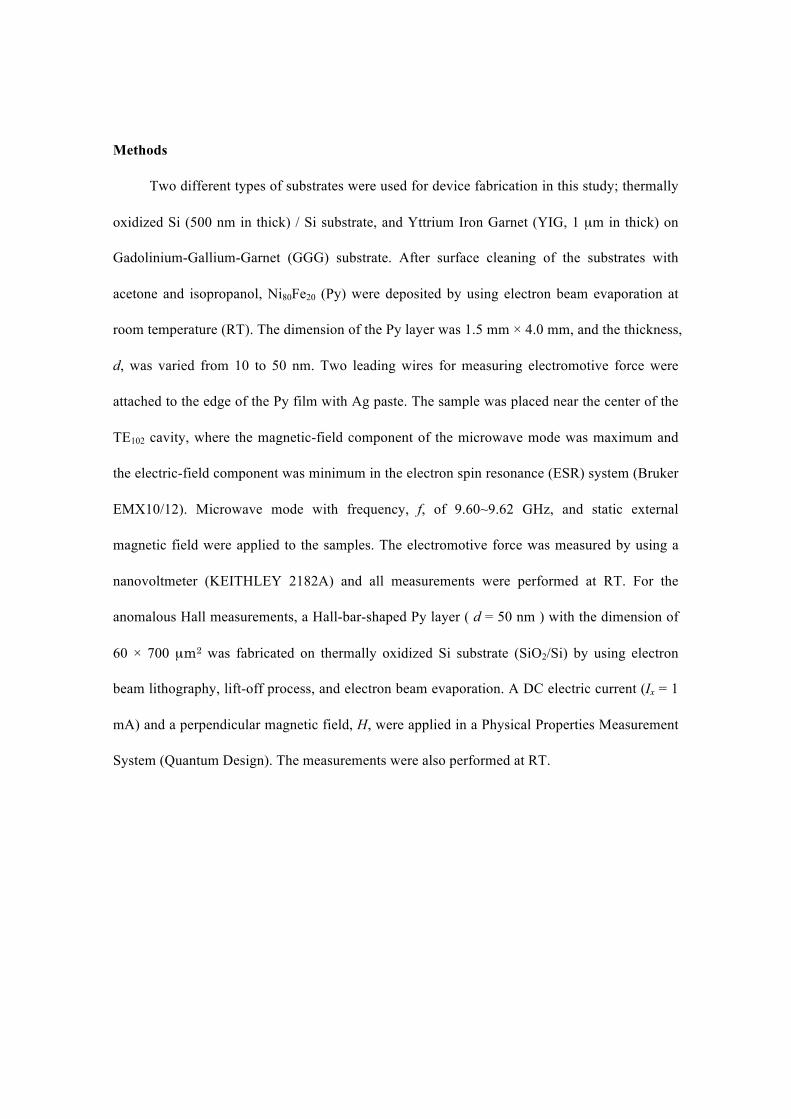
Two different types of substrates were used for device fabrication in this study; thermally
oxidized Si (500 nm in thick) / Si substrate, and Yttrium Iron Garnet (YIG, 1 µm in thick) on
Gadolinium-Gallium-Garnet (GGG) substrate. After surface cleaning of the substrates with
acetone and isopropanol, Ni80Fe20 (Py) were deposited by using electron beam evaporation at
room temperature (RT). The dimension of the Py layer was 1.5 mm × 4.0 mm, and the thickness,
d, was varied from 10 to 50 nm. Two leading wires for measuring electromotive force were
attached to the edge of the Py film with Ag paste. The sample was placed near the center of the
TE102 cavity, where the magnetic-field component of the microwave mode was maximum and
the electric-field component was minimum in the electron spin resonance (ESR) system (Bruker
EMX10/12). Microwave mode with frequency, f, of 9.60~9.62 GHz, and static external
magnetic field were applied to the samples. The electromotive force was measured by using a
nanovoltmeter (KEITHLEY 2182A) and all measurements were performed at RT. For the
anomalous Hall measurements, a Hall-bar-shaped Py layer ( d = 50 nm ) with the dimension of
60 × 700 µm2 was fabricated on thermally oxidized Si substrate (SiO2/Si) by using electron
beam lithography, lift-off process, and electron beam evaporation. A DC electric current (Ix = 1
mA) and a perpendicular magnetic field, H, were applied in a Physical Properties Measurement
System (Quantum Design). The measurements were also performed at RT.

References
[1] Jedema, F. J., Filip, A. T. & van Wees, B. J. Electrical spin injection and accumulation at
room temperature in an all-metal mesoscopic spin valve. Nature 410, 345-348 (2001).
[2] Jedema, F. J., Heersche, H. B., Filip, A. T., Baselmans, J. J. A. & van Wees, B. J. Electrical
detection of spin precession in a metallic mesoscopic spin valve. Nature 416, 713-716 (2002).
[3] Mizukami, S., Ando, Y. & Miyazaki, T. Effect of spin diffusion on Gilbert damping for a
very thin permalloy layer in Cu/permalloy/Cu/Pt films. Phys. Rev. B 66, 104413 (2002).
[4] Saitoh, E., Ueda, M., Miyajima, H. & Tatara, G. Conversion of spin current into charge
current at room temperature: Inverse spin-Hall effect. Appl. Phys. Lett. 88, 182509 (2006).
[5] Tserkovnyak, Y., Brataas, A. & Bauer, G. E. W. Enhanced Gilbert Damping in Thin
Ferromagnetic Films. Phys Rev. Lett. 88, 117601 (2002).
[6] Brataas, A., Tserkovnyak, Y., Bauer, G. E. W. & Halperin, B. I. Spin battery operated by
ferromagnetic resonance. Phys Rev. B 66, 060404(R) (2002).
[7] Tserkovnyak, Y., Brataas, A., Bauer, G. E. W. & Halperin, B. I., Nonlocal magnetization
dynamics in ferromagnetic heterostructures. Rev. Mod. Phys. 77, 1375-1421 (2005).
[8] Valenzuela, S. O. & Tinkham, M. Direct electronic measurement of the spin Hall effect.
Nature 442, 176-179 (2006).
[9] Kimura, T., Otani, Y., Sato, T., Takahashi, S., Maekawa, S., Phys Rev. Lett. 98, 156601
(2007).
[10] Ando, K., et al. Angular dependence of inverse spin–Hall effect induced by spin pumping
investigated in a Ni81Fe19/Pt thin film. Phys. Rev. B 78, 014413 (2008).
[11] Ando, K., et al. Electrically tunable spin injector free from the impedance mismatch
problem. Nature Mater. 10, 655-659 (2011).
[12] Shikoh, E., et al., Spin-pumping-induced spin transport in p-type Si at room temperature.

Submitted.
[13] Koike, M., et al. Dynamical Spin Injection into p-type Germanium at Room Temperature.
Appl. Phys. Express, Accepted
[14] Kajiwara, Y., et al., Transmission of electrical signals by spin-wave interconversion in a
magnetic insulator. Nature 464, 262-266 (2010).
[15] Huang, S. Y., et al., Intrinsic Spin-Dependent Thermal Transport. Phys Rev. Lett. 107,
216604 (2011).
[16] Weiler, M., et al., Local Charge and Spin Currents in Magnetothermal Landscapes, Phys
Rev. Lett. 108, 106602 (2012).
[17] Kato, R. & Hatta, I. Thermal conductivity measurement of thermally-oxidized SiO2 films
on a silicon wafer using a thermo-reflectance technique. International Journal of
Thermophysics 26, 1 (2005).
[18] Padture, N. P. & Klemens, P. G. Low Thermal Conductivity in Garnets. J. Am. Ceram. Soc.
80, 1028-1020 (1997).
[19] Lemmon, E. W. & Jacobsen, R. T. Viscosity and Thermal Conductivity Equations for
Nitrogen, Oxygen, Argon, and Air. International Journal of Thermophysics 25, 1(2004).
[20] Parker, W. J., et al. Flash method of determining thermal diffusivity, heat capacity, and
thermal conductivity. J. Appl. Phys. 32, 1679 (1961).
[21] Ando, K. & Saitoh, E. Inverse spin-Hall effect in palladium at room temperature. J.
Appl.Phys. 108, 113925 (2010).
[22] Ando, K., et al. E. Inverse spin-Hall effect induced by spin pimping in metallic system.
J.Appl. Phys. 109, 103913 (2011).
[23] Naito, T., Hirashima, D. S., & Kontani, H. Tight-binding study of anomalous Hall effect in
ferromagnetic 3d transition metals. Phys. Rev. B 81, 195111 (2010).

[24] Shhindler, A. I. & Salkovitz, E. I. Ferromagnetic Hall Coefficient of Nickel Alloys.
Physical Review 99, 1251-1252 (1955).
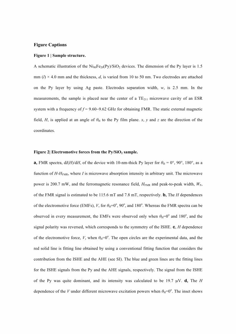
Figure Captions
Figure 1 | Sample structure.
A schematic illustration of the Ni80Fe20(Py)/SiO2 devices. The dimension of the Py layer is 1.5
mm (l) × 4.0 mm and the thickness, d, is varied from 10 to 50 nm. Two electrodes are attached
on the Py layer by using Ag paste. Electrodes separation width, w, is 2.5 mm. In the
measurements, the sample is placed near the center of a TE211 microwave cavity of an ESR
system with a frequency of f = 9.60~9.62 GHz for obtaining FMR. The static external magnetic
field, H, is applied at an angle of θH to the Py film plane. x, y and z are the direction of the
coordinates.
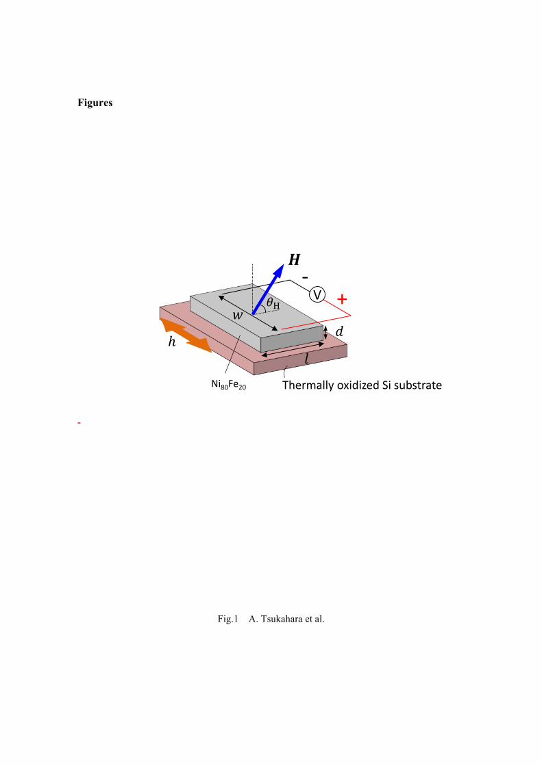
Figure 2| Electromotive forces from the Py/SiO2 sample.
a, FMR spectra, dI(H)/dH, of the device with 10-nm-thick Py layer for θH = 0°, 90°, 180°, as a
function of H-HFMR, where I is microwave absorption intensity in arbitrary unit. The microwave
power is 200.7 mW, and the ferromagnetic resonance field, HFMR and peak-to-peak width, WF,
of the FMR signal is estimated to be 115.6 mT and 7.8 mT, respectively. b, The H dependences
of the electromotive force (EMFs), V, for θH=0o, 90o, and 180o. Whereas the FMR spectra can be
observed in every measurement, the EMFs were observed only when θH=0o and 180o, and the
signal polarity was reversed, which corresponds to the symmetry of the ISHE. c, H dependence
of the electromotive force, V, when θH=0o. The open circles are the experimental data, and the
red solid line is fitting line obtained by using a conventional fitting function that considers the
contribution from the ISHE and the AHE (see SI). The blue and green lines are the fitting lines
for the ISHE signals from the Py and the AHE signals, respectively. The signal from the ISHE
of the Py was quite dominant, and its intensity was calculated to be 19.7 µV. d, The H
dependence of the V under different microwave excitation powers when θH=0o. The inset shows

microwave power dependence of the VISHE and the VAHE, where the VISHE and VAHE are the
magnitudes of the electromotive forces due to the ISHE and the AHE, respectively.
Figure 3| An electromotive force from Al/Py/YIG.
a, The H dependence of the FMR signal, dI(H)/dH, when θH=0o for Al/Py/YIG sample (solid
line in orange). The FMR signal for Py/SiO2/Si sample is also displayed as black solid line. A
thin Al layer (4 nm in thick) was deposited onto the Py (10 nm in thick) in order to prevent
oxidation of the Py. The procedures of the measurements of EMFs and the geometry of the
sample are the same as those of the Py(10 nm)/SiO2/Si sample. HFMR and WF is estimated to be
107.3 mT and 3.4 mT, respevtively. b, The H dependence of the electromotive force, V,
measured for the Py(10nm)/YIG, when θH=0o. The open circles are the experimental data and
the red solid line is a fitting line obtained by using a conventional fitting function that considers
the contribution from the ISHE and the AHE (see also Supplementary Information). The blue
and green lines are the fitting lines for the ISHE signals from the Py and the AHE signals,
respectively. The notable is that the EMF by the ISHE from this sample is quite small and the
ISHE was estimated to be 2.7 µV.
Figure 4| A schematic of a simple model for estimating the spin Hall angle of the Py.
a, Pure spin current, js0 , is generated from an infinitesimal layer, dy, at the position of ζ from
the interface of the Py/SiO2 under the FMR, and flows to the interface as observed in the
experiment. The js0 is converted to a charge current due to the ISHE typically within a length
scale of spin diffusion length, λF. Since the js0 is uniformly generated in the Py, the total
charge current can be calculated by integrating the contribution from the layer, dy, in the

thickness of the Py in the y direction. b, The VISHE as a function of the Py thickness for the
Py/SiO2 sample. The solid lines are theoretical lines of the EMF predicted for a variety of the
θSHE (0.002, 0.018 and 0.030), where the spin diffusion length in the Py at RT was set to be 3
nm [9] and the spin current density calculated from Eq. (1) was 1.06! 10-9 J/m2. Red closed
circles show the experimental data and the error bars show the standard deviation.
Figure 5| Hall voltage measurements for the Py/SiO2.
a, A schematic illustration of the Py/SiO2 sample for Hall effect measurement. The dimension
of the Py layer was 60 µm × 700 µm and the thickness, d, was set to be 50 nm. A dc current, I,
of 1 mA and a perpendicular magnetic field, H, are applied. b, The H dependence of the Hall
voltage for the Py/SiO2 sample. The linear relationship between the Hall voltages and the H
above 1 T is reasonably explained by the Hall effect and the red line is a linear fit of the data
above 1 T. The anomalous Hall voltage of the Py layer is obtained from the ordinate intercept of
the fitting line.
Figures
-
Fig.1 A. Tsukahara et al.
V
Ni80Fe20 Thermally oxidized Si substrate
+-‐

Fig.2 A. Tsukahara et al
c
d
ba
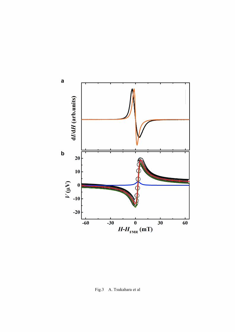
Fig.3 A. Tsukahara et al
(a)
(b)
a
b
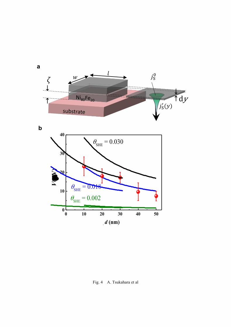
Fig. 4 A. Tsukahara et al
0 10 20 30 40 500
10
20
30
40θSHE = 0.030
θSHE = 0.002
θSHE = 0.018
V(µ
V)
the thickness of the Ni80Fe20 d (nm)0 10 20 30 40 50
0
10
20
30
40
V (µ
V)
the thickness of Py d (nm)0 10 20 30 40 50
0
10
20
30
40θSHE = 0.030
θSHE = 0.002
θSHE = 0.018
V(µ
V)
the thickness of the Ni80Fe20 d (nm)
a
b
dy
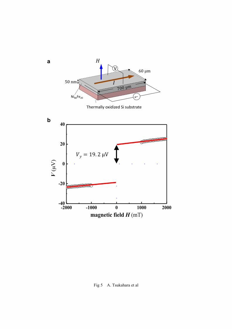
Fig 5 A. Tsukahara et al
-2000 -1000 0 1000 2000-40
-20
0
20
40
1 mA fitting curve
V (µ
V)
magnetic field H (mT)-2000 -1000 0 1000 2000
-40
-20
0
20
40
1 mA fitting curve
V (µ
V)
magnetic field H (mT)
Ni80Fe20
Thermally oxidized Si substrate
Va
b

Supplementary Information
Observation of the intrinsic inverse spin Hall effect in Ni80Fe20
Ayaka Tsukahara #, Yuta Kitamura #, Eiji Shikoh ,
Yuichiro Ando, Teruya Shinjo and Masashi Shiraishi *#
Graduate School of Engineering Science, Osaka University, 5608531, Toyonaka, Japan
A. Deconvolution of the electromotive force signals
Since, contribution from anomalous Hall effect (AHE) is included in the EMF, deconvolutiton
of the signals is important. In general, EMF-H curves have been analyzed by using following fitting
function [1] ;
.
Here, Γ denotes the damping constant and HFMR is the ferromagnetic resonance field (115.6 mT for
θH = 0° in this study). The first term, which has a symmetrical Lorentzian shape, corresponds to the
contributions from the ISHE, whereas the second term, which has an asymmetrical shape,
corresponds to that from the AHE. For 10nm-thick Py/SiO2/Si sample, whose EMF is shown in Fig.
1b in the main text, VISHE is estimated to be 19.7 μV, which is larger than that from ferromagnetic
metal / nonmagnetic metal samples such as Py/Pd in previous studies. The ratio VISHE/VAHE is
estimated to be 7.3, indicating that the EMF is due to ISHE of Py is dominant.
V =VISHE!2
(H "HFMR )2 +!2
+VAHE"2!(H "HFMR )(H "HFMR )
2 +!2

B. Electromotive force from Py/YIG/GGG samples
In Fig. 3 of the paper, a 4 nm-thick Al layer has been deposited on Py/YIG/GGG sample in
order to prevent oxidation of the Py layer and obtain an intrinsic FMR spectra of the Py layer. We
also revealed that the EMF, due to ISHE in the Py layer, is not sensitive to existence of Al layer.
Figure S1 shows FMR spectrum and EMF for Py/YIG/GGG sample without Al layer. The separation
of the two contacts is ~1.3 mm. The signal shape of the EMF is almost the same with that of the
Py/YIG/GGG sample with Al layer. In fact, the magnitude ratio VISHE/VAHE is estimated to be 0.19,
which is close to that of the Py/YIG/GGG sample with Al layer (0.17).
Fig. S1 The H dependence of a the FMR signal, dI(H)/dH, and b the electromotive force, V,
when θH=0o for Py/YIG sample. The open circles in Fig. S1b are the experimental data and the
red solid line is a fitting line obtained by using a conventional fitting function that considers the
contribution from the ISHE and the AHE. The blue and green lines are the fitting lines for the

ISHE signals from the Py and the AHE signals, respectively.
References
[1] Saitoh, E., Ueda, M., Miyajima, H. & Tatara, G. Conversion of spin current into charge current at
room temperature: Inverse spin-Hall effect. Appl. Phys. Lett. 88, 182509 (2006).