OBJECTIVES - g-w.com presentation. They aid in ... tasks, such as drawing basic shapes, lettering,...
18
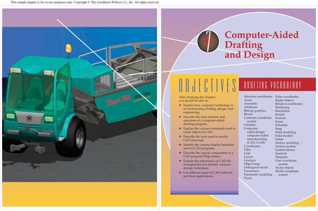
150 Exploring Drafting Chapter 7 Computer-Aided Drafting and Design 151 OBJECTIVES After studying this chapter, you should be able to: ◆ Explain how computer technology is revolutionizing drafting, design, and engineering. ◆ Describe the basic features and operation of a computer-aided drafting program. ◆ Explain the various commands used to create objects in CAD. ◆ Describe the tools used to modify CAD drawings. ◆ Identify the various display functions used in CAD programs. ◆ Describe the typical components in a CAD program Help system. ◆ Explain the importance of CAD file management and identify common storage techniques. ◆ List different types of CAD software and their applications. Computer-Aided Drafting and Design Drafting vocabulary 7 Absolute coordinates Array Assembly Attributes Bitmap graphics Blocks Cartesian coordinate system Chamfer Computer- aided design/ computer-aided manufacturing (CAD/CAM) Coordinates Fillet Grid Layers Linetype Object snap Orthogonal mode Parameters Parametric modeling Pixels Polar coordinates Raster objects Relative coordinates Rendering Resolution Round Scanner Scene Schedule Snap Solid modeling Solid models Solids Surface modeling Surface models Symbol library Symbols Template User coordinate system Vector objects World coordinate system This sample chapter is for review purposes only. Copyright © The Goodheart-Willcox Co., Inc. All rights reserved.
Transcript of OBJECTIVES - g-w.com presentation. They aid in ... tasks, such as drawing basic shapes, lettering,...
150 Exploring Drafting Chapter 7 Computer-Aided Drafting and Design 151
O B J E C T I V E SAfter studying this chapter, you should be able to:◆ Explain how computer technology is
revolutionizing drafting, design, and engineering.
◆ Describe the basic features and operation of a computer-aided drafting program.
◆ Explain the various commands used to create objects in CAD.
◆ Describe the tools used to modify CAD drawings.
◆ Identify the various display functions used in CAD programs.
◆ Describe the typical components in a CAD program Help system.
◆ Explain the importance of CAD fi le management and identify common storage techniques.
◆ List different types of CAD software and their applications.
Computer-Aided Drafting and Design
D r a f t i n g v o c a b u l a r y
7
Absolute coordinatesArrayAssemblyAttributesBitmap graphicsBlocksCartesian coordinate
systemChamferComputer-
aided design/computer-aided manufacturing (CAD/CAM)
CoordinatesFilletGridLayersLinetypeObject snapOrthogonal modeParametersParametric modelingPixels
Polar coordinatesRaster objectsRelative coordinatesRenderingResolutionRoundScannerSceneScheduleSnapSolid modelingSolid modelsSolidsSurface modelingSurface modelsSymbol librarySymbolsTemplateUser coordinate
systemVector objectsWorld coordinate
system
This sample chapter is for review purposes only. Copyright © The Goodheart-Willcox Co., Inc. All rights reserved.
152 Exploring Drafting
Computer graphics continues to revolu-tionize drafting and engineering, Figure 7-1. Computer-aided drafting and design systems play an integral part in the entire engineering process, from design and drafting to analysis and presentation. They aid in designing mech-anical products, buildings, and many other types of manufactured and constructed items.
There are many benefi ts to using CAD as a design and drafting tool. Traditional drafting tasks, such as drawing basic shapes, lettering, and creating views, are greatly simplifi ed with the electronic tools of a CAD system. CAD pro-grams provide setup tools, drawing and edit-ing commands, and customization methods to maximize accuracy and profi ciency. There is a wide range of programs to choose from depending on the nature of the work. This chapter introduces the various applications of CAD drafting and discusses the common tools used to create CAD drawings.
Overview of Computer Graphics and CAD
Computer graphics was fi rst employed for aerospace design in the 1950s. It is now
a required tool of industrial technology. Until the advent of CAD, engineers, designers, and drafters had to imagine and then evaluate a three-dimensional object that was drawn in two dimensions on a fl at sheet of paper. The only way a design could be verifi ed in three dimensions was to make a wood, clay, plaster, or plastic model. This is an expensive and time-consuming process.
The emergence of CAD provided design-ers with a dynamic new tool. CAD technology permits more time for creative work because it eliminates the repetitive tasks required in traditional drafting.
CAD is a computer graphics technology that allows users to generate and display 2D and 3D designs electronically, Figure 7-2.Many people are able to use a computer drawing program after a suitable training period. However, the principles of drafting are fundamental to both traditional drafting and CAD. A working knowledge of basic drafting standards, techniques, and procedures is absolutely necessary to be an effective CAD drafter.
The main function of a CAD designer or engineer is to defi ne the basic shape of a part, assembly, or product in 2D or 3D form. The
Figure 7-1 Computer-aided drafting systems are used for a wide variety of applications in design and engineering. With the proper CAD program, it is possible to generate realistic three-dimensional models representing complex mechanical products. (Autodesk, Inc.)
Figure 7-2 A 3D drawing created with a typical CAD system. With the proper tools, 2D and 3D representations of the object being designed can be generated. (Autodesk, Inc.)
Chapter 7 Computer-Aided Drafting and Design 153
process involves many changes and refi ne-ments before a design is fi nalized. With a CAD system, design changes can be made and evaluated quickly.
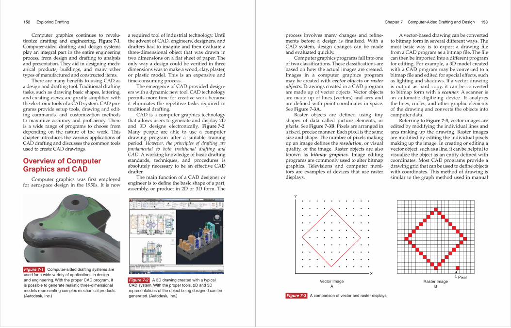
Computer graphics programs fall into one of two classifi cations. These classifi cations are based on how the actual images are created. Images in a computer graphics program may be created with vector objects or raster objects. Drawings created in a CAD program are made up of vector objects. Vector objects are made up of lines (vectors) and arcs and are defi ned with point coordinates in space. See Figure 7-3A.
Raster objects are defi ned using tiny shapes of data called picture elements, or pixels. See Figure 7-3B. Pixels are arranged in a fi xed, precise manner. Each pixel is the same size and shape. The number of pixels making up an image defi nes the resolution, or visual quality, of the image. Raster objects are also known as bitmap graphics. Image editing programs are commonly used to alter bitmap graphics. Televisions and computer moni-tors are examples of devices that use raster displays.
A vector-based drawing can be converted to bitmap form in several different ways. The most basic way is to export a drawing fi le from a CAD program as a bitmap fi le. The fi le can then be imported into a different program for editing. For example, a 3D model created with a CAD program may be converted to a bitmap fi le and edited for special effects, such as lighting and shadows. If a vector drawing is output as hard copy, it can be converted to bitmap form with a scanner. A scanner is an automatic digitizing device. It analyzes the lines, circles, and other graphic elements of the drawing and converts the objects into computer data.
Referring to Figure 7-3, vector images are edited by modifying the individual lines and arcs making up the drawing. Raster images are modifi ed by editing the individual pixels making up the image. In creating or editing a vector object, such as a line, it can be helpful to visualize the object as an entity defi ned with coordinates. Most CAD programs provide a drawing grid that can be used to defi ne objects with coordinates. This method of drawing is similar to the graph method used in manual
Vector ImageA
Raster ImageB
• • • • • • • • • •
•••••••••
• • • • • • • •
••••••••
• • • • • • • •
• • • • • • • •
• • • • • • • •
• • • • • • • •
• • • • • • • •
• • • • • • • • •
X
Y
Pixel
Figure 7-3 A comparison of vector and raster displays.
154 Exploring Drafting
drafting. The graph method, discussed in Chapter 3, is used to enlarge or reduce draw-ings with coordinate grids. When using a CAD program, objects can be drawn to the desired size by defi ning coordinates or other parameters or by scaling an original object to a different size. Coordinate entry, scaling, and other types of drawing functions in CAD programs are discussed later in this chapter.
How CAD WorksA CAD drawing project starts with
the generation of a geometric model of the proposed design. The base outline or profi le of the design is created fi rst and then features are added. CAD models are created in 2D or 3D form, depending on the type of program being used and the purpose of the project.
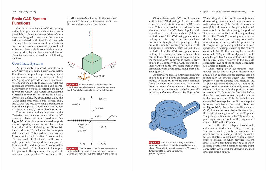
Instructions are given to a CAD program through the use of commands. Commands can be picked from “ribbon” or “command manager” tabs, selected from pull-down menus, or entered at the keyboard. See Figure 7-4. Toolbars and palettes may also be available for selecting commands. A typical CAD software interface normally provides
a number of ways to execute commands and functions.
Once objects are drawn, they can be altered as needed. For example, an object can be moved, rotated, copied, deleted, or mirrored. An object drawn in CAD can be manipulated in a variety of ways, making it unnecessary to draw the object again.
Dimensions and text can be added to a CAD drawing by selecting the appropriate command or function and entering the required information. The drafter can defi ne the text size, style, and orientation as needed. CAD functions for creating text and dimen-sions are discussed later in this text.
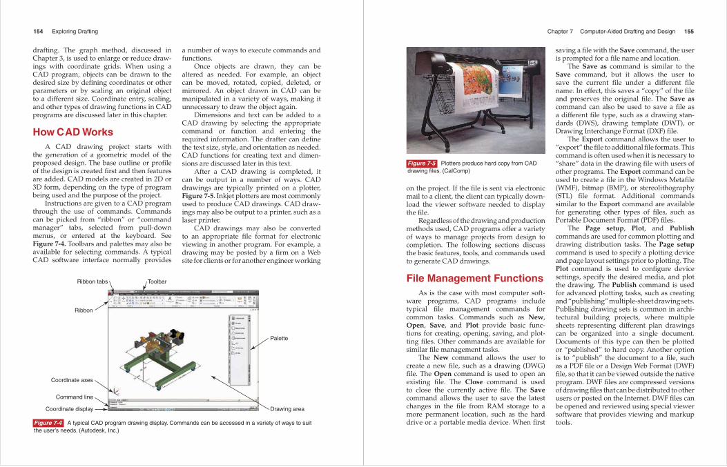
After a CAD drawing is completed, it can be output in a number of ways. CAD drawings are typically printed on a plotter, Figure 7-5. Inkjet plotters are most commonly used to produce CAD drawings. CAD draw-ings may also be output to a printer, such as a laser printer.
CAD drawings may also be converted to an appropriate fi le format for electronic viewing in another program. For example, a drawing may be posted by a fi rm on a Web site for clients or for another engineer working
Ribbon tabs
Ribbon
Coordinate display
Command line
Coordinate axes
Toolbar
Palette
Drawing area
Figure 7-4 A typical CAD program drawing display. Commands can be accessed in a variety of ways to suit the user’s needs. (Autodesk, Inc.)
Chapter 7 Computer-Aided Drafting and Design 155
on the project. If the fi le is sent via electronic mail to a client, the client can typically down-load the viewer software needed to display the fi le.
Regardless of the drawing and production methods used, CAD programs offer a variety of ways to manage projects from design to completion. The following sections discuss the basic features, tools, and commands used to generate CAD drawings.
File Management FunctionsAs is the case with most computer soft-
ware programs, CAD programs include typical fi le management commands for common tasks. Commands such as New, Open, Save, and Plot provide basic func-tions for creating, opening, saving, and plot-ting fi les. Other commands are available for similar fi le management tasks.
The New command allows the user to create a new fi le, such as a drawing (DWG) fi le. The Open command is used to open an existing fi le. The Close command is used to close the currently active fi le. The Save command allows the user to save the latest changes in the fi le from RAM storage to a more permanent location, such as the hard drive or a portable media device. When fi rst
saving a fi le with the Save command, the user is prompted for a fi le name and location.
The Save as command is similar to the Save command, but it allows the user to save the current fi le under a different fi le name. In effect, this saves a “copy” of the fi le and preserves the original fi le. The Save as command can also be used to save a fi le as a different fi le type, such as a drawing stan-dards (DWS), drawing template (DWT), or Drawing Interchange Format (DXF) fi le.
The Export command allows the user to “export” the fi le to additional fi le formats. This command is often used when it is necessary to “share” data in the drawing fi le with users of other programs. The Export command can be used to create a fi le in the Windows Metafi le (WMF), bitmap (BMP), or stereolithography (STL) fi le format. Additional commands similar to the Export command are available for generating other types of fi les, such as Portable Document Format (PDF) fi les.
The Page setup, Plot, and Publish commands are used for common plotting and drawing distribution tasks. The Page setup command is used to specify a plotting device and page layout settings prior to plotting. The Plot command is used to confi gure device settings, specify the desired media, and plot the drawing. The Publish command is used for advanced plotting tasks, such as creating and “publishing” multiple-sheet drawing sets. Publishing drawing sets is common in archi-tectural building projects, where multiple sheets representing different plan drawings can be organized into a single document. Documents of this type can then be plotted or “published” to hard copy. Another option is to “publish” the document to a fi le, such as a PDF fi le or a Design Web Format (DWF) fi le, so that it can be viewed outside the native program. DWF fi les are compressed versions of drawing fi les that can be distributed to other users or posted on the Internet. DWF fi les can be opened and reviewed using special viewer software that provides viewing and markup tools.
Figure 7-5 Plotters produce hard copy from CAD drawing fi les. (CalComp)
156 Exploring Drafting
Basic CAD System Functions
One of the main benefi ts of CAD drafting is the added productivity and effi ciency made possible by tools in the software. Many of these tools are designed to automate the common tasks associated with traditional (manual) drafting. There are a number of basic features and functions common to most types of CAD software. These include coordinate systems, drawing aids, layers, linetypes, and blocks. These features are discussed in the following sections.
Coordinate SystemsAs previously discussed, objects in a
CAD drawing are defi ned with coordinates. Coordinates are points representing units of real measurement from a fi xed point. Most CAD programs provide a basic coordinate system and the ability to create user-defi ned coordinate systems. The most basic coordi-nate system in a typical program is the world coordinate system. This system is based on the Cartesian coordinate system. In this system, objects are defi ned by coordinates along the X axis (horizontal axis), Y axis (vertical axis), and Z axis (the axis projecting perpendicular from the XY plane). Coordinates are located in relation to the 0,0,0 origin. See Figure 7-6.
The horizontal and vertical axes of the Cartesian coordinate system divide the XY drawing plane into four quadrants. See Figure 7-7. Coordinates are entered as posi-tive or negative, depending on the location from the origin. Referring to Figure 7-7, the coordinate (2,2) is located in the upper-right quadrant. This quadrant has positive X coordinates and positive Y coordinates. The coordinate (4,–3) is located in the lower-right quadrant. This quadrant has positive X coordinates and negative Y coordinates. The coordinate (–6,8) is located in the upper-left quadrant. This quadrant has negative X coordinates and positive Y coordinates. The
(–X,+Y)
(–6,8)
Y axis
(+X,+Y)
(2,2) X axis
(4,–3)Origin(0,0)
(–3,–5)
(–X,–Y) (+X,–Y)
Figure 7-7 The XY axes of the Cartesian coordinate system divide the drawing plane into four quadrants. Coordinates have positive or negative X and Y values.
Z a
xis
Y axis
Y X
Origin (0,0,0) Z
X axis
Figure 7-6 In the Cartesian coordinate system, coordinates establish points of measurement along the X, Y, and Z axes in relation to the 0,0,0 origin.
coordinate (–3,–5) is located in the lower-left quadrant. This quadrant has negative X coor-dinates and negative Y coordinates.
Chapter 7 Computer-Aided Drafting and Design 157
Figure 7-8 A third axis (the Z axis) is needed to generate three-dimensional drawings like the one shown. The ability to visualize objects in 3D space is fundamental to creating 3D drawings. (ROBO Systems)
Objects drawn with XY coordinates are suffi cient for 2D drawings. A third coordi-nate axis, the Z axis, is required for 3D draw-ings. This axis is used for coordinate entry above or below the XY plane. A point with a positive Z coordinate, such as (0,0,1), is located “above” the XY drawing plane. When looking at a drawing on screen, this loca-tion can be thought of as a point projecting out of the monitor toward you. A point with a negative Z coordinate, such as (0,0,–1), is located “below” the XY drawing plane. When looking at a drawing on screen, this location can be thought of as a point projecting into the monitor away from you. In order to draw objects in 3D space with a CAD system, it is important to be able to visualize them in three dimensions with coordinates along each axis. See Figure 7-8.
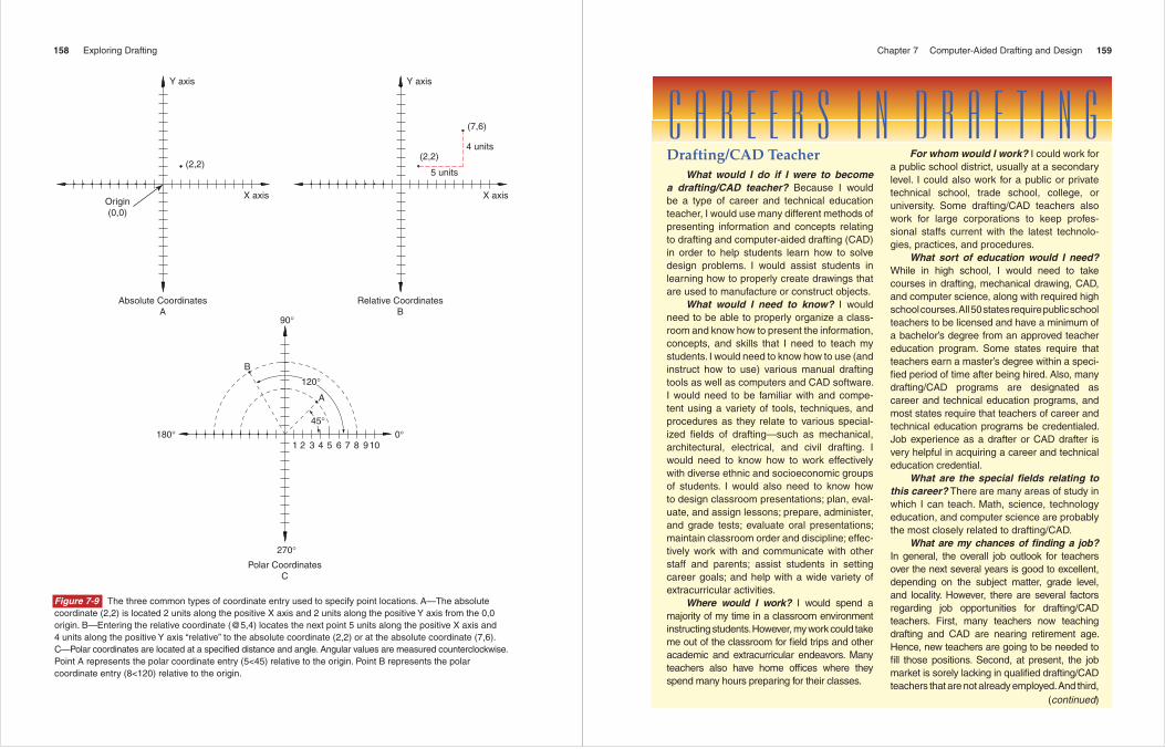
A basic way to locate points when drawing objects is to pick points on screen using the mouse. In addition, there are three common forms of coor dinate entry used to specify point locations. Coordinates can be entered as absolute coordinates, relative coordi-nates, or polar coordinates. See Figure 7-9.
When using absolute coordinates, objects are drawn using points in relation to the coordi-nate system origin (0,0). The absolute coordi-nate (2,2) indicates that the point is located two units from the origin along the positive X axis and two units from the origin along the positive Y axis. When using relative coor-dinates, objects are drawn using coordinates in relation to the last coordinate specifi ed (or the origin, if a previous point has not been specifi ed). For example, entering the relative coordinate (@5,4) after entering the absolute coordinate (2,2) places the next point fi ve units along the positive X axis and four units along the positive Y axis “relative” to the absolute coordinate (2,2) or at the absolute coordinate (7,6). Refer to Figure 7-9B.
When using polar coordinates, coor-dinates are located at a given distance and angle. Polar coordinates are entered using a format such as (distance<angle). This format specifi es a linear distance and angle in the XY plane relative to the previous point or the origin. Angles are most commonly measured counterclockwise, with the positive X axis representing 0°. Entering the @ symbol before the polar coordinate locates the point relative to the previous point. If the @ symbol is not entered before the polar coordinate, the point is located relative to the origin. Referring to Figure 7-9C, the polar coordinate entry (5<45) locates the point fi ve units away from the origin at an angle of 45° in the XY plane. The polar coordinate entry (8<120) locates the point eight units away from the origin at an angle of 120° in the XY plane.
Each of the different types of coordinate entry can be used when creating a drawing. The entry used typically depends on the object drawn. For example, it may be useful to use absolute coordinates when a given point is known, or when drawing straight lines. Relative coordinates may be used when locating points from a common feature. Polar coordinates are useful for drawing inclined lines and round objects.
158 Exploring Drafting
Y axis
(2,2)
X axis
Absolute CoordinatesA
Origin(0,0)
Y axis
(2,2)
(7,6)
X axis
Relative CoordinatesB
5 units
4 units
90°
180°
120°
45°
1 2 3 4 5 6 7 8 9 10
270°
0°
Polar CoordinatesC
A
B
Figure 7-9 The three common types of coordinate entry used to specify point locations. A—The absolute coordinate (2,2) is located 2 units along the positive X axis and 2 units along the positive Y axis from the 0,0 origin. B—Entering the relative coordinate (@5,4) locates the next point 5 units along the positive X axis and 4 units along the positive Y axis “relative” to the absolute coordinate (2,2) or at the absolute coordinate (7,6). C—Polar coordinates are located at a specifi ed distance and angle. Angular values are measured counterclockwise. Point A represents the polar coordinate entry (5<45) relative to the origin. Point B represents the polar coordinate entry (8<120) relative to the origin.
Chapter 7 Computer-Aided Drafting and Design 159
C A R E E R s i n d r a f t i n gDrafting/CAD Teacher
What would I do if I were to become a drafting/CAD teacher? Because I would be a type of career and technical education teacher, I would use many different methods of presenting information and concepts relating to drafting and computer-aided drafting (CAD) in order to help students learn how to solve design problems. I would assist students in learning how to properly create drawings that are used to manufacture or construct objects.
What would I need to know? I would need to be able to properly organize a class-room and know how to present the information, concepts, and skills that I need to teach my students. I would need to know how to use (and instruct how to use) various manual drafting tools as well as computers and CAD software. I would need to be familiar with and compe-tent using a variety of tools, techniques, and procedures as they relate to various special-ized fi elds of drafting—such as mechanical, architectural, electrical, and civil drafting. I would need to know how to work effectively with diverse ethnic and socioeconomic groups of students. I would also need to know how to design classroom presentations; plan, eval-uate, and assign lessons; prepare, administer, and grade tests; evaluate oral presentations; maintain classroom order and discipline; effec-tively work with and communicate with other staff and parents; assist students in setting career goals; and help with a wide variety of extracurricular activities.
Where would I work? I would spend a majority of my time in a classroom environment instructing students. However, my work could take me out of the classroom for fi eld trips and other academic and extracurricular endeavors. Many teachers also have home offi ces where they spend many hours preparing for their classes.
(continued)
For whom would I work? I could work for a public school district, usually at a secondary level. I could also work for a public or private technical school, trade school, college, or university. Some drafting/CAD teachers also work for large corporations to keep profes-sional staffs current with the latest technolo-gies, practices, and procedures.
What sort of education would I need? While in high school, I would need to take courses in drafting, mechanical drawing, CAD, and computer science, along with required high school courses. All 50 states require public school teachers to be licensed and have a minimum of a bachelor’s degree from an approved teacher education program. Some states require that teachers earn a master’s degree within a speci-fi ed period of time after being hired. Also, many drafting/CAD programs are designated as career and technical education programs, and most states require that teachers of career and technical education programs be credentialed. Job experience as a drafter or CAD drafter is very helpful in acquiring a career and technical education credential.
What are the special fi elds relating to this career? There are many areas of study in which I can teach. Math, science, technology education, and computer science are probably the most closely related to drafting/CAD.
What are my chances of fi nding a job? In general, the overall job outlook for teachers over the next several years is good to excellent, depending on the subject matter, grade level, and locality. However, there are several factors regarding job opportunities for drafting/CAD teachers. First, many teachers now teaching drafting and CAD are nearing retirement age. Hence, new teachers are going to be needed to fi ll those positions. Second, at present, the job market is sorely lacking in qualifi ed drafting/CAD teachers that are not already employed. And third,
160 Exploring Drafting
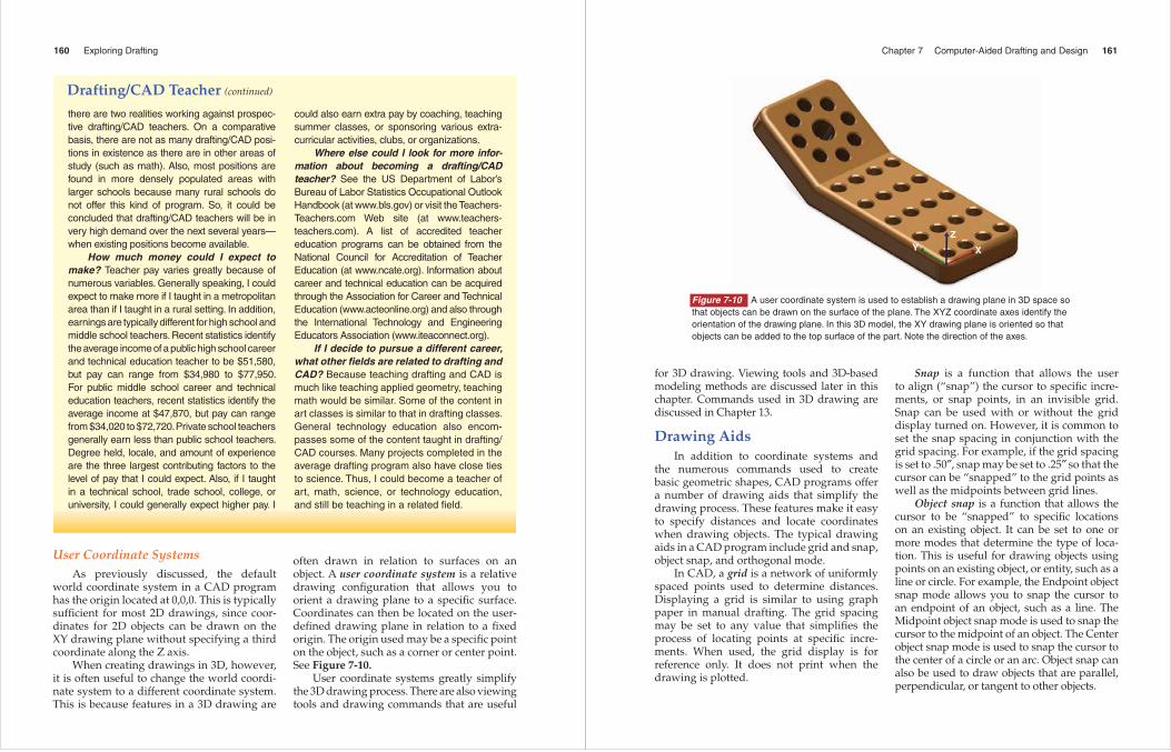
often drawn in relation to surfaces on an object. A user coordinate system is a relative drawing confi guration that allows you to orient a drawing plane to a specifi c surface. Coordinates can then be located on the user-defi ned drawing plane in relation to a fi xed origin. The origin used may be a specifi c point on the object, such as a corner or center point. See Figure 7-10.
User coordinate systems greatly simplify the 3D drawing process. There are also viewing tools and drawing commands that are useful
User Coordinate SystemsAs previously discussed, the default
world coordinate system in a CAD program has the origin located at 0,0,0. This is typically suffi cient for most 2D drawings, since coor-dinates for 2D objects can be drawn on the XY drawing plane without specifying a third coordinate along the Z axis.
When creating drawings in 3D, however, it is often useful to change the world coordi-nate system to a different coordinate system. This is because features in a 3D drawing are
there are two realities working against prospec-tive drafting/CAD teachers. On a comparative basis, there are not as many drafting/CAD posi-tions in existence as there are in other areas of study (such as math). Also, most positions are found in more densely populated areas with larger schools because many rural schools do not offer this kind of program. So, it could be concluded that drafting/CAD teachers will be in very high demand over the next several years—when existing positions become available.
How much money could I expect to make? Teacher pay varies greatly because of numerous variables. Generally speaking, I could expect to make more if I taught in a metropolitan area than if I taught in a rural setting. In addition, earnings are typically different for high school and middle school teachers. Recent statistics identify the average income of a public high school career and technical education teacher to be $51,580, but pay can range from $34,980 to $77,950. For public middle school career and technical education teachers, recent statistics identify the average income at $47,870, but pay can range from $34,020 to $72,720. Private school teachers generally earn less than public school teachers. Degree held, locale, and amount of experience are the three largest contributing factors to the level of pay that I could expect. Also, if I taught in a technical school, trade school, college, or university, I could generally expect higher pay. I
could also earn extra pay by coaching, teaching summer classes, or sponsoring various extra-curricular activities, clubs, or organizations.
Where else could I look for more infor-mation about becoming a drafting/CAD teacher? See the US Department of Labor’s Bureau of Labor Statistics Occupational Outlook Handbook (at www.bls.gov) or visit the Teachers-Teachers.com Web site (at www.teachers-teachers.com). A list of accredited teacher education programs can be obtained from the National Council for Accreditation of Teacher Education (at www.ncate.org). Information about career and technical education can be acquired through the Association for Career and Technical Education (www.acteonline.org) and also through the International Technology and Engineering Educators Association (www.iteaconnect.org).
If I decide to pursue a different career, what other fi elds are related to drafting and CAD? Because teaching drafting and CAD is much like teaching applied geometry, teaching math would be similar. Some of the content in art classes is similar to that in drafting classes. General technology education also encom-passes some of the content taught in drafting/CAD courses. Many projects completed in the average drafting program also have close ties to science. Thus, I could become a teacher of art, math, science, or technology education, and still be teaching in a related fi eld.
Drafting/CAD Teacher (continued)
Chapter 7 Computer-Aided Drafting and Design 161
for 3D drawing. Viewing tools and 3D-based modeling methods are discussed later in this chapter. Commands used in 3D drawing are discussed in Chapter 13.
Drawing AidsIn addition to coordinate systems and
the numerous commands used to create basic geometric shapes, CAD programs offer a number of drawing aids that simplify the drawing process. These features make it easy to specify distances and locate coordinates when drawing objects. The typical drawing aids in a CAD program include grid and snap, object snap, and orthogonal mode.
In CAD, a grid is a network of uniformly spaced points used to determine distances. Displaying a grid is similar to using graph paper in manual drafting. The grid spacing may be set to any value that simplifi es the process of locating points at specifi c incre-ments. When used, the grid display is for reference only. It does not print when the drawing is plotted.
Snap is a function that allows the user to align (“snap”) the cursor to specifi c incre-ments, or snap points, in an invisible grid. Snap can be used with or without the grid display turned on. However, it is common to set the snap spacing in conjunction with the grid spacing. For example, if the grid spacing is set to .50″, snap may be set to .25″ so that the cursor can be “snapped” to the grid points as well as the midpoints between grid lines.
Object snap is a function that allows the cursor to be “snapped” to specifi c locations on an existing object. It can be set to one or more modes that determine the type of loca-tion. This is useful for drawing objects using points on an existing object, or entity, such as a line or circle. For example, the Endpoint object snap mode allows you to snap the cursor to an endpoint of an object, such as a line. The Midpoint object snap mode is used to snap the cursor to the midpoint of an object. The Center object snap mode is used to snap the cursor to the center of a circle or an arc. Object snap can also be used to draw objects that are parallel, perpendicular, or tangent to other objects.
X
ZY
Figure 7-10 A user coordinate system is used to establish a drawing plane in 3D space so that objects can be drawn on the surface of the plane. The XYZ coordinate axes identify the orientation of the drawing plane. In this 3D model, the XY drawing plane is oriented so that objects can be added to the top surface of the part. Note the direction of the axes.
162 Exploring Drafting
Orthogonal mode simplifi es the task of drawing horizontal and vertical lines. When orthogonal mode is enabled, the movement of the cursor is confi ned to horizontal and vertical movement on the drawing plane. Inclined lines cannot be drawn when using this mode. Orthogonal mode is useful for drawing lines at 90° angles, such as the outlines making up a drawing border.
Layers and LinetypesIn manual drafting, it is common to have
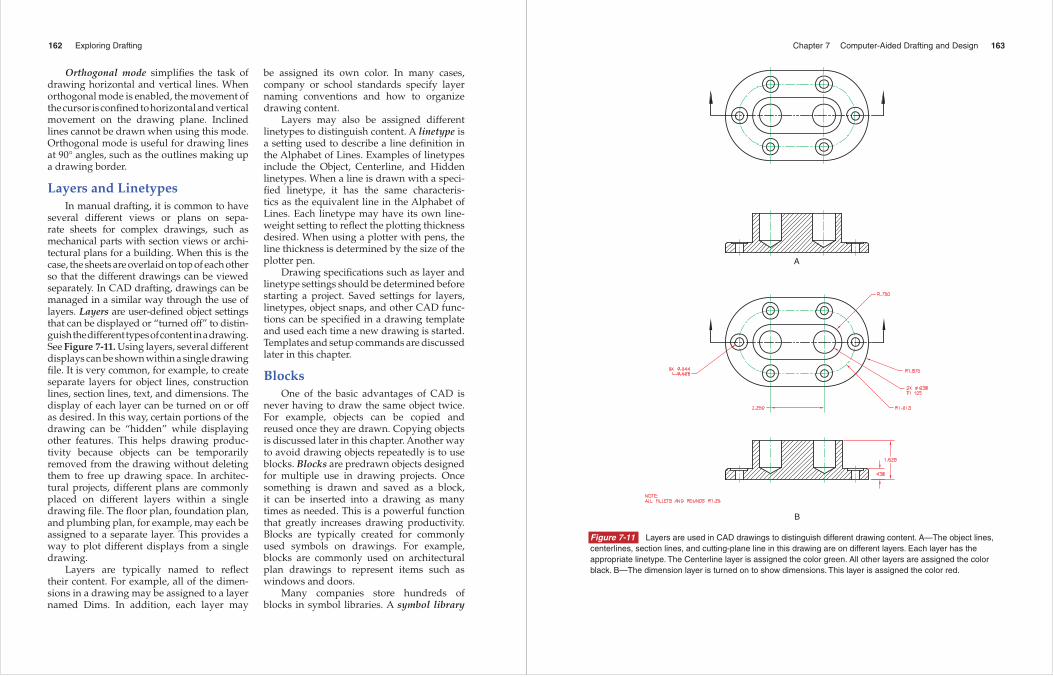
several different views or plans on sepa-rate sheets for complex drawings, such as me chanical parts with section views or archi-tectural plans for a building. When this is the case, the sheets are overlaid on top of each other so that the different drawings can be viewed separately. In CAD drafting, drawings can be managed in a similar way through the use of layers. Layers are user-defi ned object settings that can be displayed or “turned off” to distin-guish the different types of content in a drawing. See Figure 7-11. Using layers, several different displays can be shown within a single drawing fi le. It is very common, for example, to create separate layers for object lines, construction lines, section lines, text, and dimensions. The display of each layer can be turned on or off as desired. In this way, certain portions of the drawing can be “hidden” while displaying other features. This helps drawing produc-tivity because objects can be temporarily removed from the drawing without deleting them to free up drawing space. In architec-tural projects, different plans are commonly placed on different layers within a single drawing fi le. The fl oor plan, foundation plan, and plumbing plan, for example, may each be assigned to a separate layer. This provides a way to plot different displays from a single drawing.
Layers are typically named to refl ect their content. For example, all of the dimen-sions in a drawing may be assigned to a layer named Dims. In addition, each layer may
be assigned its own color. In many cases, company or school standards specify layer naming conventions and how to organize drawing content.
Layers may also be assigned different linetypes to distinguish content. A linetype is a setting used to describe a line defi nition in the Alphabet of Lines. Examples of linetypes include the Object, Centerline, and Hidden linetypes. When a line is drawn with a speci-fi ed linetype, it has the same characteris-tics as the equivalent line in the Alphabet of Lines. Each linetype may have its own line-weight setting to refl ect the plotting thickness desired. When using a plotter with pens, the line thickness is determined by the size of the plotter pen.
Drawing specifi cations such as layer and linetype settings should be determined before starting a project. Saved settings for layers, linetypes, object snaps, and other CAD func-tions can be specifi ed in a drawing template and used each time a new drawing is started. Templates and setup commands are discussed later in this chapter.
BlocksOne of the basic advantages of CAD is
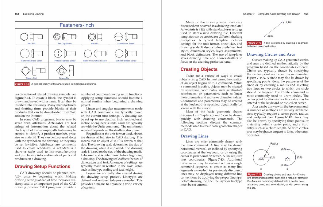
never having to draw the same object twice. For example, objects can be copied and reused once they are drawn. Copying objects is discussed later in this chapter. Another way to avoid drawing objects repeatedly is to use blocks. Blocks are predrawn objects designed for multiple use in drawing projects. Once something is drawn and saved as a block, it can be inserted into a drawing as many times as needed. This is a powerful function that greatly increases drawing productivity. Blocks are typically created for commonly used symbols on drawings. For example, blocks are commonly used on architectural plan drawings to represent items such as windows and doors.
Many companies store hundreds of blocks in symbol libraries. A symbol library
Chapter 7 Computer-Aided Drafting and Design 163
A
B
Figure 7-11 Layers are used in CAD drawings to distinguish different drawing content. A—The object lines, centerlines, section lines, and cutting-plane line in this drawing are on different layers. Each layer has the appropriate linetype. The Centerline layer is assigned the color green. All other layers are assigned the color black. B—The dimension layer is turned on to show dimensions. This layer is assigned the color red.
164 Exploring Drafting
Hex Bolt Hex Cap Screw Hex Nut Slotted Oval Screw
Slotted Panhead Screw Phillips Flathead Screw Slotted Roundhead Screw Slotted Flathead Screw
Square Bolt Square Nut
Fasteners-Inch
Figure 7-12 A symbol library of fasteners used in mechanical drafting.
is a collection of related drawing symbols. See Figure 7-12. To create a block, the symbol is drawn and saved with a name. It can then be inserted into drawings. Many manufacturers and drafting fi rms provide blocks of their products that can be downloaded from Web sites on the Internet.
In some CAD programs, blocks may be saved with attributes. Attributes are text strings of information about the related block symbol. For example, attributes may be created to identify a product number, price, size, or material. They can be displayed along with the symbol on the drawing, or they may be set invisible. Attributes are commonly used to create schedules. A schedule is a chart or table used to list manufacturing and purchasing information about parts and products on a drawing.
Drawing Setup FunctionsCAD drawings should be planned care-
fully prior to beginning work. Making drawing settings ahead of time increases effi -ciency and is an important part of the CAD drawing process. CAD programs provide a
number of common drawing setup functions. Applying setup functions should become a normal routine when beginning a drawing project.
Linear and angular measurements made with CAD commands are typically based on the current unit settings. A drawing can be set up to use decimal inch, architectural, metric, or engineer’s units. Units are typically set with the Units command. The unit format selected depends on the drafting discipline.
Regardless of the unit format used, objects are drawn at full size in CAD drafting. This means that an object 2″ × 3″ is drawn at that size. The drawing scale determines the size of the drawing when it is plotted. The drawing scale is based on the size of the drawing media to be used and is determined before beginning a drawing. The drawing scale affects the size of dimensions and text. A number of settings are typically made in relation to the scale factor, such as linetype scaling and text height.
Layers are normally also created during the drawing setup process. Linetypes are defi ned and assigned to layers as needed. This provides a means to organize a wide variety of content.
Chapter 7 Computer-Aided Drafting and Design 165
(11,10)
(6,6)
•
•
Figure 7-13 A line is created by drawing a segment between two coordinates.
Many of the drawing aids previously discussed can be saved in a drawing template. A template is a fi le with standard user settings used to start a new drawing fi le. Different templates can be created for different drafting disciplines. A typical template includes settings for the unit format, sheet size, and drawing scale. It also includes predefi ned text styles, dimension styles, layer assignments, and block defi nitions. The use of templates saves drawing time and allows drafters to focus on the drawing project at hand.
Creating ObjectsThere are a variety of ways to create
objects using CAD. In most cases, the creation of an object begins with a command. While a command is active, objects may be created by specifying coordinates, such as absolute coordinates, or parameters, such as linear measurements and radius or diameter values. Coordinates and parameters may be entered at the keyboard or specifi ed dynamically on screen with the cursor.
Most of the basic geometric shapes discussed in Chapters 3 and 6 can be drawn quickly with drawing commands. The following sections discuss the common methods used to create basic geometric shapes in CAD.
Drawing LinesLines are most commonly drawn with
the Line command. A line may be drawn horizontal, vertical, or inclined by specifying coordinates at the keyboard or by using the cursor to pick points on screen. A line requires two coordinates, Figure 7-13. Additional coordinates may be entered within a single command sequence to create as many line segments as needed. As previously discussed, lines may be displayed using different line conventions by applying the proper linetype. Before drawing the line, the layer or linetype must be set current.
Drawing Circles and ArcsCurves making up CAD-generated circles
and arcs are defi ned mathematically by the program based on the coordinates entered. Circles are typically drawn by specifying the center point and a radius or diameter, Figure 7-14A. A circle may also be drawn by specifying points along the perimeter of the circle or by entering a radius and selecting two lines or two circles to which the circle should be tangent. The Circle command is most commonly used to draw circles. The center point location and radius value may be entered at the keyboard or picked on screen.
Arcs can be drawn with the Arc command. A number of methods are usually available. Arcs typically require a center point, radius, and endpoint. See Figure 7-14B. Arcs may also be drawn by specifying three points, or a starting point, a center point, and a third entry, such as a chord length. As with circles, arcs may be drawn tangent to lines, other arcs, or circles.
Radius
A B
(3,0)
(0,3)
(0,0)
(0,-3)
(3,0)(0,0)
• • •
•
•
•
Figure 7-14 Drawing circles and arcs. A—Circles are defi ned with a center point and a radius or diameter. B—Arcs are commonly defi ned with a center point, a starting point, and an endpoint, or with points along the arc.
166 Exploring Drafting
A c a d e m i c l i n kThe evolution of computer technology
and electronic communication has had a major effect on the way drawings are made and presented. Not long ago, manual draw-ings were the primary means of commu-nicating manufacturing information to trade workers. Today, drawings are created with computer-aided drafting programs and dis-tributed with electronic media. They are used by workers to program computer-controlled machine tools. Computers then interpret the information and manufacture parts. This is accomplished through various phases of com-munication—including interaction between the drafter and the computer and the computer and a machine.
There are literally hundreds of CAD soft-ware programs that have been used to design
products for industrial use. Computer anima-tion programs make it possible to communi-cate an entire design of a product before it is manufactured or built. Internet technology makes it possible to send, receive, evaluate, and modify drawings in a very short period of time.
When compared to manual drawing tech-niques, CAD tools have made it much simpler to communicate information. However, it is important to understand that as with other communication tools, CAD is only a tool. The same drawing skills, visualization techniques, and concepts practiced in manual drafting must be understood in order to use CAD accurately and successfully.
Minor axisSecond axisendpoint
Center point
First axisendpointMajor axis
•
••
•
•
Figure 7-15 An ellipse is drawn by defi ning a center point and endpoints for the minor and major axes.
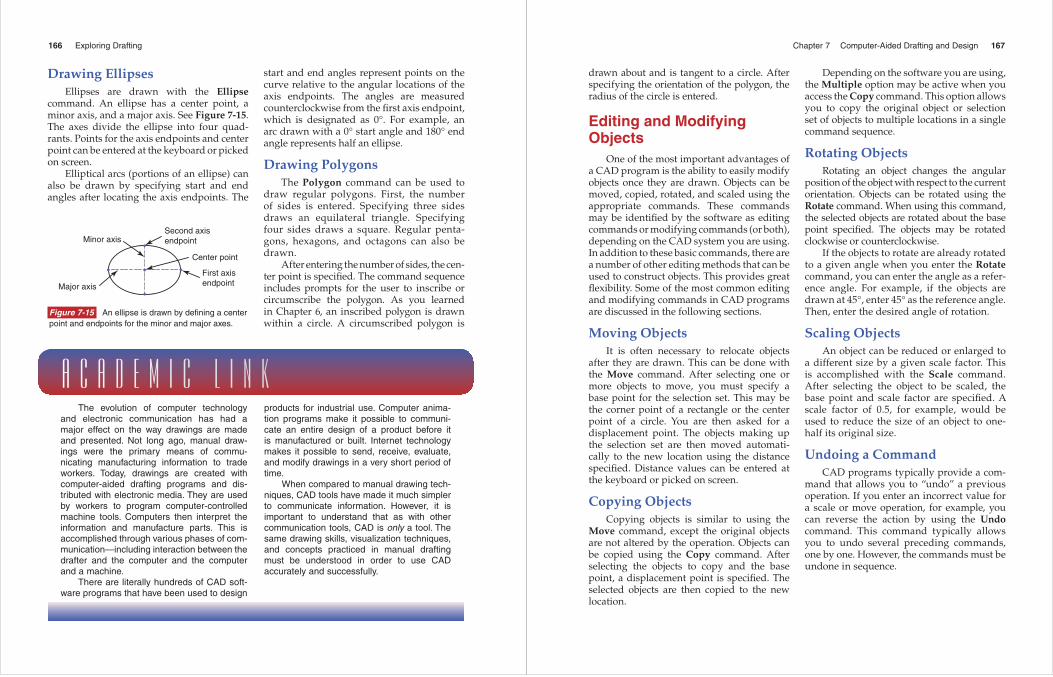
Drawing EllipsesEllipses are drawn with the Ellipse
command. An ellipse has a center point, a minor axis, and a major axis. See Figure 7-15. The axes divide the ellipse into four quad-rants. Points for the axis endpoints and center point can be entered at the keyboard or picked on screen.
Elliptical arcs (portions of an ellipse) can also be drawn by specifying start and end angles after locating the axis endpoints. The
start and end angles represent points on the curve relative to the angular locations of the axis endpoints. The angles are measured counterclockwise from the fi rst axis endpoint, which is designated as 0°. For example, an arc drawn with a 0° start angle and 180° end angle represents half an ellipse.
Drawing PolygonsThe Polygon command can be used to
draw regular polygons. First, the number of sides is entered. Specifying three sides draws an equilateral triangle. Specifying four sides draws a square. Regular penta-gons, hexagons, and octagons can also be drawn.
After entering the number of sides, the cen-ter point is specifi ed. The command sequence includes prompts for the user to inscribe or circumscribe the polygon. As you learned in Chapter 6, an inscribed polygon is drawn within a circle. A circumscribed polygon is
Chapter 7 Computer-Aided Drafting and Design 167
drawn about and is tangent to a circle. After specifying the orientation of the polygon, the radius of the circle is entered.
Editing and Modifying Objects
One of the most important advantages of a CAD program is the ability to easily modify objects once they are drawn. Objects can be moved, copied, rotated, and scaled using the appropriate commands. These commands may be identifi ed by the software as editing commands or modifying commands (or both), depending on the CAD system you are using. In addition to these basic commands, there are a number of other editing methods that can be used to construct objects. This provides great fl exibility. Some of the most common editing and modifying commands in CAD programs are discussed in the following sections.
Moving ObjectsIt is often necessary to relocate objects
after they are drawn. This can be done with the Move command. After selecting one or more objects to move, you must specify a base point for the selection set. This may be the corner point of a rectangle or the center point of a circle. You are then asked for a displacement point. The objects making up the selection set are then moved automati-cally to the new location using the distance specifi ed. Distance values can be entered at the keyboard or picked on screen.
Copying ObjectsCopying objects is similar to using the
Move command, except the original objects are not altered by the operation. Objects can be copied using the Copy command. After selecting the objects to copy and the base point, a displacement point is specifi ed. The selected objects are then copied to the new location.
Depending on the software you are using, the Multiple option may be active when you access the Copy command. This option allows you to copy the original object or selection set of objects to multiple locations in a single command sequence.
Rotating ObjectsRotating an object changes the angular
position of the object with respect to the current orientation. Objects can be rotated using the Rotate command. When using this command, the selected objects are rotated about the base point specifi ed. The objects may be rotated clockwise or counterclockwise.
If the objects to rotate are already rotated to a given angle when you enter the Rotatecommand, you can enter the angle as a refer-ence angle. For example, if the objects are drawn at 45°, enter 45° as the reference angle. Then, enter the desired angle of rotation.
Scaling ObjectsAn object can be reduced or enlarged to
a different size by a given scale factor. This is accomplished with the Scale command. After selecting the object to be scaled, the base point and scale factor are specifi ed. A scale factor of 0.5, for example, would be used to reduce the size of an object to one-half its original size.
Undoing a CommandCAD programs typically provide a com-
mand that allows you to “undo” a previous operation. If you enter an incorrect value for a scale or move operation, for example, you can reverse the action by using the Undocommand. This command typically allows you to undo several preceding commands, one by one. However, the commands must be undone in sequence.
168 Exploring Drafting
Erasing ObjectsThe Erase command provides a quick
way to remove unwanted objects from a drawing. After you select the objects to erase, the command automatically removes them from the drawing. The Undo command can be used to restore an object that has been erased unintentionally.
Arraying ObjectsAn array of objects can be created by
orienting multiple copies of a selected object in a pattern. This operation is useful when the same object appears in multiple locations in a regular pattern in the drawing (for example, when a pattern of holes is machined in a round part). Arrays may be created in rectangular or polar arrangements with the Array command. See Figure 7-16. A rectangular array is created by entering the base point, number of rows, number of columns, and the spacing between rows and columns. The number of columns
and rows determines the number of objects in the array. A polar array is created by speci-fying a center point, the number of objects in the array, and an angular value determining the amount of rotation. Entering 360° creates a full rotation of objects about the center point.
Mirroring ObjectsWhen drawing symmetrical objects, it is
sometimes useful to create a mirror image. This operation allows you to select an object and make a mirror copy. This can save time when you want to draw half of an object and complete it by “mirroring” it. See Figure 7-17. The Mirror command is used to mirror an object. To use this command, the objects to be mirrored are fi rst selected. Then, a mirror axis is specifi ed. The axis represents a line about which the objects are “refl ected.” The command sequence typically allows you to keep or delete the original objects selected before mirroring.
Creating Rounded and Angled Corners
Rounded and angled corners are often drawn in mechanical drafting. A round is an arc representing an outside rounded corner. A
Originalobject
A
Original object
B
Figure 7-16 Arrays are created by orienting copies of original objects in a regular pattern. A—Rectangular array. B—Polar array.
Original objects Objects after mirroring
(0,0)
Figure 7-17 Mirroring an object creates a mirror copy about a mirror axis. In this example, the original image is mirrored twice using the X and Y axes.
Chapter 7 Computer-Aided Drafting and Design 169
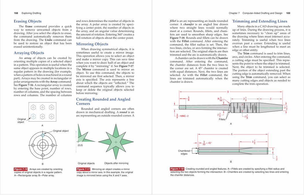
fi llet is an arc representing an inside rounded corner. A chamfer is an angled line drawn where two straight lines would normally meet at a corner. Rounds, fi llets, and cham-fers are used to smoothen sharp edges. See Figure 7-18. Rounds and fi llets can be drawn with the Fillet command. After entering the command, the fi llet radius is set. Then, the two lines, circles, or arcs forming the intersec-tion are selected. The original objects are then trimmed and the arc is automatically drawn.
A chamfer can be drawn with the Chamfer command. After entering the command, the chamfer distances from the two lines to the corner are set. A 45° chamfer is created with equal distances. Next, the two lines are selected. As with the Fillet command, the lines are trimmed automatically when the chamfer is drawn.
Trimming and Extending LinesMany objects in a CAD drawing are made
up of lines. During the drawing process, it is sometimes necessary to “clean up” areas of the drawing where lines must intersect accu-rately. Trimming is useful when two lines overrun past a corner. Extending is useful when a line must be lengthened to meet an edge or other entity.
The Trim command is used to trim lines, arcs, and circles. After entering the command, a cutting edge must be specifi ed. This repre-sents the point to where the object is trimmed. Next, the object to be trimmed is selected. The portion of the object exten ding past the cutting edge is automatically removed. When using the Trim command, you can select as many cutting edges and objects as needed to complete the trim operation.
A
B
1_2
2
1_2
2
3_16
R
1_2
∅
7_8
∅1_2
1_2
3_8
5_8
∅
2
9
–16NC–2
3_32 × 45°
Fillets
6
Chamferededges
Figure 7-18 Creating rounded and angled features. A—Fillets are created by specifying a fi llet radius and selecting the two objects forming the intersection. B—Chamfers are created by selecting two lines and entering the chamfer distances.
170 Exploring Drafting
The Extend command is used to extend lines and arcs to meet other objects. After entering the command, a boundary edge must be specifi ed. This represents the point to where the object is extended. Next, the object to be extended is selected. The object is then extended to the boundary to create a larger entity. As with the Trim command, you can select as many cutting edges and objects as needed to complete the extend operation.
Using Display CommandsThere are a variety of ways to display
drawing content on screen when working on a CAD drawing. Display commands are used to change the magnifi cation of the drawing, change the viewpoint, and establish drawing views, such as the views in a multiview drawing. Multiview drawings are discussed in Chapter 9.
When working on a CAD drawing, it is often necessary to “zoom” into certain portions to view features. The Zoom command provides this capability. After entering the command, you can zoom into a portion of the drawing by windowing around the display. The windowed portion is then shown at a greater magnifi cation scale. You can also enter a magnifi cation scale factor to reduce or enlarge the display relative to the current display. A third option allows you to zoom the view in real time by using the pointing device to move the cursor upward (to enlarge the view) or downward (to reduce the view).
When you want to move the drawing across the screen to view areas outside of the current display without changing the magnifi -cation, you can use the Pan command. Panning adjusts the view in real time. The drawing is panned by using the pointing device to move the cursor in the direction desired.
More advanced viewing commands are available with 3D drawing programs. While command names and navigation methods will vary, 3D viewing commands typically allow you to rotate a 3D model in three
dimensions by using the pointing device. The view is changed in real time, allowing you to view different features across the model dynamically.
Using Measurement, Object Property, and Drawing Status Commands
During the drawing process, it is common to check measurements of existing objects to verify accuracy and confi rm that design requirements are met. Measurements are also needed to determine the correct dimensions when constructing new features in relation to other features. CAD programs typically provide commands to make measurements of existing objects and determine other infor-mation, such as object properties and current drawing fi le data.
Measurement commands allow you to quickly determine common measurements, such as linear distances and area and perim-eter calculations. The Measure Geometry command allows you to select two points and measure the distance and/or angle between them. You can also use this command to determine the radius or diameter of a circle or arc by selecting the object. When using the Measure Geometry command to determine the area or perimeter of a closed object or a specifi c area, you must select the object or pick the points defi ning the area.
Common object properties, such as layer and linetype settings, can be identi-fi ed by using the Properties command. After entering the command and selecting an object, the program displays various informa-tion, including the object coordinates and the layer, linetype, and color settings assigned to the object.
Other commands are available for deter-mining additional information about objects in the current drawing and data associated with the drawing fi le. The List command allows you to select one or more objects and
Chapter 7 Computer-Aided Drafting and Design 171
list information from the database about each object. The Status command allows you to identify the drawing limits and other statistics, including the number of objects in the drawing, the current drawing settings, and the amount of free space on the drive where the fi le is stored. The Time command allows you to display the current date and time, the drawing time in the current session, and the date and time the drawing was created.
Using Help System Functions
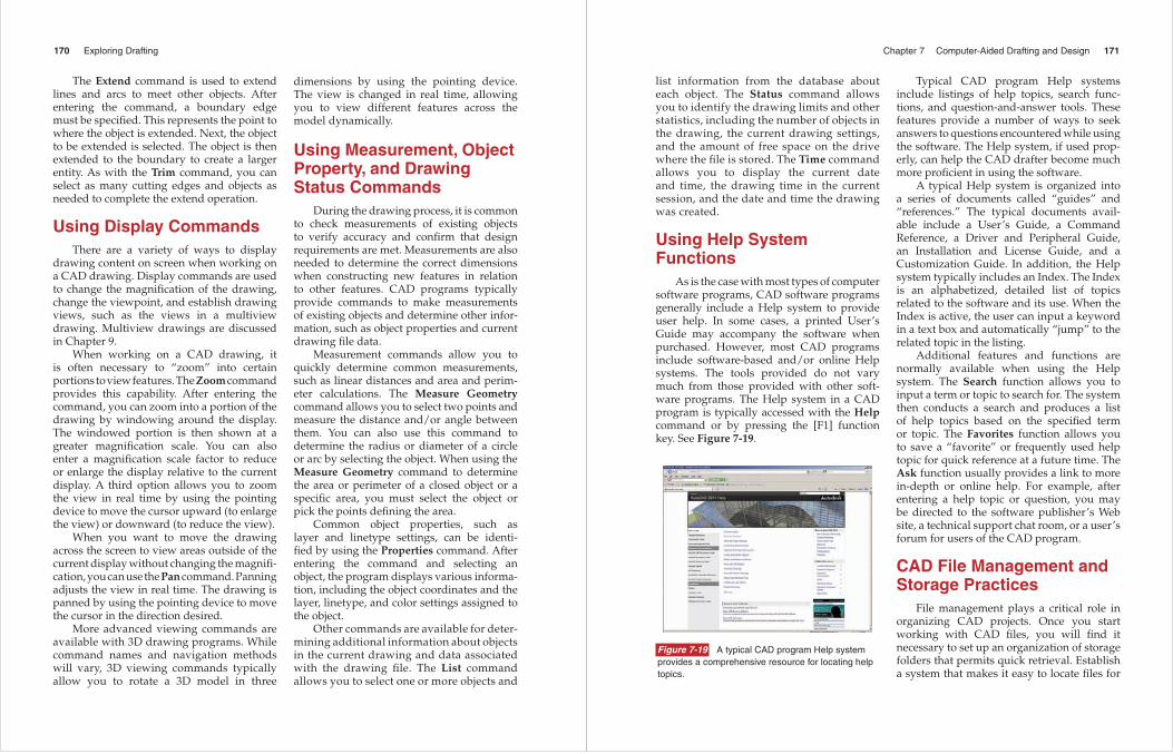
As is the case with most types of computer software programs, CAD software programs generally include a Help system to provide user help. In some cases, a printed User’s Guide may accompany the software when purchased. However, most CAD programs include software-based and/or online Help systems. The tools provided do not vary much from those provided with other soft-ware programs. The Help system in a CAD program is typically accessed with the Helpcommand or by pressing the [F1] function key. See Figure 7-19.
Typical CAD program Help systems include listings of help topics, search func-tions, and question-and-answer tools. These features provide a number of ways to seek answers to questions encountered while using the software. The Help system, if used prop-erly, can help the CAD drafter become much more profi cient in using the software.
A typical Help system is organized into a series of documents called “guides” and “references.” The typical documents avail-able include a User’s Guide, a Command Reference, a Driver and Peripheral Guide, an Installation and License Guide, and a Customization Guide. In addition, the Help system typically includes an Index. The Index is an alphabetized, detailed list of topics related to the software and its use. When the Index is active, the user can input a keyword in a text box and automatically “jump” to the related topic in the listing.
Additional features and functions are normally available when using the Help system. The Search function allows you to input a term or topic to search for. The system then conducts a search and produces a list of help topics based on the specifi ed term or topic. The Favorites function allows you to save a “favorite” or frequently used help topic for quick reference at a future time. The Ask function usually provides a link to more in-depth or online help. For example, after entering a help topic or question, you may be directed to the software publisher’s Web site, a technical support chat room, or a user’s forum for users of the CAD program.
CAD File Management and Storage Practices
File management plays a critical role in organizing CAD projects. Once you start working with CAD fi les, you will fi nd it necessary to set up an organization of storage folders that permits quick retrieval. Establish a system that makes it easy to locate fi les for
Figure 7-19 A typical CAD program Help system provides a comprehensive resource for locating help topics.
172 Exploring Drafting
a given project. For example, you may want to establish a top-level folder for each project and include subfolders named to refl ect their contents. Using this approach, you might decide to have a top-level folder for an archi-tectural building project and subfolders that are named to identify the different plan draw-ings created in each phase of the project. A system such as this one might have subfolders with names such as First Floor, Second Floor, Electrical, HVAC, and Plumbing.
It is also important to establish consistent fi le naming conventions to accurately iden-tify the contents of fi les. This makes it easy to locate fi les and improves productivity. It is common, for example, to use prefi xes in fi le names to identify information such as the project code and drawing discipline. Your school may already have established conven-tions for naming fi les. If so, make sure to follow the conventions.
In some projects, drawing fi les include “references” to other fi les. For example, when creating an electrical plan drawing in a building project, you typically need to “reference” data from the fl oor plan drawing to help locate features based on dimensions in the fl oor layout. If the fl oor plan is “refer-enced” by the electrical plan, it becomes a “dependent” of the parent fi le. When opening the parent fi le (the electrical plan), the soft-ware must be able to locate the reference fi le (the fl oor plan). If the fi le cannot be located, you must supply the fi le path. This is another reason to maintain an orderly fi le storage system. Make sure to organize your projects so that fi les referenced by other fi les can be located by the software.
Saving, Backing Up, and Archiving Files
Whether working with manually created drawings or CAD fi les, the need for secure, organized archives of original drawings is of utmost importance. Storing manually created drawings in physical fi les requires a secure
facility, adequate organizational techniques, and plenty of space. At the same time, proper storage of CAD drawings creates an entirely different set of problems and challenges.
Since CAD drawings are electronic fi les, there must be a means of storage that protects against cybertheft, hardware failure, and fi le damage. Preventing the loss of work is a primary concern in every project. As most computer users are no doubt aware of, computers do go down periodically. Hardware fails and occasionally, power fails. Hours of work can be lost in the blink of an eye if fi les are not saved to hard drives and servers frequently.
It is for these reasons that most CAD fi rms establish a protocol of fi le storage and backup strategies. This protocol usually requires that employees save and back up their work at regular intervals. Generally, these strate-gies are very in-depth routines. A good fi le storage protocol is designed so that every-thing possible is done to guarantee that valu-able work and hours are not lost.
Your CAD instructor will probably set up a similar protocol for saving and backing up fi les. Methods will vary, but fi les are typi-cally saved on a network server and backed up to another location so that valuable work is not lost. It is defi nitely to your advantage to follow your instructor’s fi le storage and orga-nizational techniques without variation. Not following an accepted protocol may result in you having to refer to the old saying—“If you do the crime, you will pay the time!” In other words, if you don’t consistently save and back up your work often, there is always a chance that you will end up doing it again.
A typical protocol for achieving safe and reliable fi le storage may include the following: 1. Save your work every 15 minutes. 2. Save fi les to a network server rather than a
local hard drive. Save to a network server with automatic fi le backup capability, if possible, to ensure fi le security.
Chapter 7 Computer-Aided Drafting and Design 173
3. Back up work weekly to another location separate from the network server, such as one or more portable media devices. Work can be saved to CDs, DVDs, or fl ash drives.This is just a sample protocol and will
probably vary based on your unique situation and your instructor’s recommendations.
When work is completed on a project and the fi les do not need to be used on a daily basis, an electronic fi le archive is typi-cally created. An electronic archive typically consists of all of the fi les related to a single project. This may involve hundreds of fi les and many different fi le formats. Some CAD programs provide special tools for creating fi le archives. No matter what method you use, there are several important points to keep in mind.
Files to be archived must be saved in a format and on electronic media that will be compatible with computer software and hardware of the future. Hence, the long-term usefulness of CAD fi les is of greater conse-quence than how much storage space they require. As with fi les in a currently active project, archived fi les must be accessible so that they can be located, opened, and edited if needed. The same fi le naming conventions, folder organization practices, and backup procedures used for active fi les should also be applied when assembling an electronic archive.
CAD Systems and SoftwareThere are many CAD software programs
available for a variety of applications. The type of program used normally depends on the application or drawing discipline for which it is used. CAD programs range in capability from simple 2D drawing programs to advanced 3D modeling and presenta-tion programs. While basic CAD programs require relatively inexpensive hardware to drive the system, higher-end programs may
require computer equipment costing several thousands of dollars.
As discussed in Chapter 4, a basic CAD system consists of a computer, a monitor (display device), keyboard, pointing device, and output device. Data is stored on the hard drive of the computer or on portable media. The primary component of the CAD system is the software. The software is the set of instructions that tells the computer what to do and when to do it.
CAD software programs can be classi-fi ed in several different ways. Some CAD programs provide 2D drawing capability only. These programs have many of the func-tions discussed in this chapter, with the excep-tion of 3D-based tools. Other CAD programs are based on a specifi c type of 3D modeling, such as solid modeling, surface modeling, or parametric modeling. Some CAD modeling software is specifi cally designed for mechan-ical drafting and manufacturing applications. There are also advanced modeling programs used to create photorealistic renderings and animations. The following sections discuss some of the features provided by different types of CAD software.
CAD Modeling ProgramsModeling programs are used to create
realistic defi nitions of objects using 3D coordinates and a variety of 3D drawing methods. Commands in the software are used to construct a model in 3D space. The resulting model can then be shown in a picto-rial view to display the various features and surfaces. Common 3D modeling commands are discussed in Chapter 13.
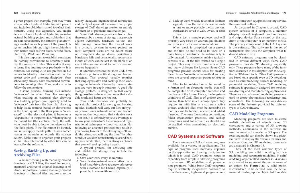
Three of the most common types of 3D modeling are solid modeling, surface modeling, and parametric modeling. In solid modeling, objects called solids or solid models are created to represent the entire mass of an object. See Figure 7-20. A solid model is considered to be defi ned from the actual material making up the object. Solid models
174 Exploring Drafting
Figure 7-20 A solid model represents the entire mass of an object and the material used in its construction. (Designed with Solid Edge from Siemens PLM Software)
are used in mechanical drafting applications because they can be analyzed for properties such as mass and volume.
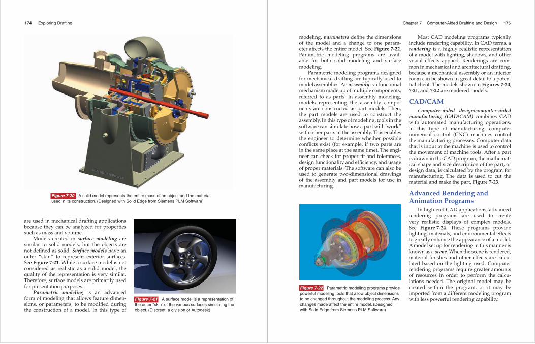
Models created in surface modeling are similar to solid models, but the objects are not defi ned as solid. Surface models have an outer “skin” to represent exterior surfaces. See Figure 7-21. While a surface model is not considered as realistic as a solid model, the quality of the representation is very similar. Therefore, surface models are primarily used for presentation purposes.
Parametric modeling is an advanced form of modeling that allows feature dimen-sions, or parameters, to be modifi ed during the construction of a model. In this type of
Figure 7-21 A surface model is a representation of the outer “skin” of the various surfaces simulating the object. (Discreet, a division of Autodesk)
Chapter 7 Computer-Aided Drafting and Design 175
modeling, parameters defi ne the dimensions of the model and a change to one param-eter affects the entire model. See Figure 7-22. Parametric modeling programs are avail-able for both solid modeling and surface modeling.
Parametric modeling programs designed for mechanical drafting are typically used to model assemblies. An assembly is a functional mechanism made up of multiple components, referred to as parts. In assembly modeling, models representing the assembly compo-nents are constructed as part models. Then, the part models are used to construct the assembly. In this type of modeling, tools in the software can simulate how a part will “work” with other parts in the assembly. This enables the engineer to determine whether possible confl icts exist (for example, if two parts are in the same place at the same time). The engi-neer can check for proper fi t and tolerances, design functionality and effi ciency, and usage of proper materials. The software can also be used to generate two-dimensional drawings of the assembly and part models for use in manufacturing.
Most CAD modeling programs typically include rendering capability. In CAD terms, a rendering is a highly realistic representation of a model with lighting, shadows, and other visual effects applied. Renderings are com-mon in mechanical and architectural drafting, because a mechanical assembly or an interior room can be shown in great detail to a poten-tial client. The models shown in Figures 7-20, 7-21, and 7-22 are rendered models.
CAD/CAMComputer-aided design/computer-aided
manufacturing (CAD/CAM) combines CAD with automated manufacturing operations. In this type of manufacturing, computer numerical control (CNC) machines control the manufacturing processes. Computer data that is input to the machine is used to control the movement of machine tools. After a part is drawn in the CAD program, the mathemat-ical shape and size description of the part, or design data, is calculated by the program for manufacturing. The data is used to cut the material and make the part, Figure 7-23.
Advanced Rendering and Animation Programs
In high-end CAD applications, advanced rendering programs are used to create very realistic displays of complex models. See Figure 7-24. These programs provide lighting, materials, and environmental effects to greatly enhance the appearance of a model. A model set up for rendering in this manner is known as a scene. When the scene is rendered, material fi nishes and other effects are calcu-lated based on the lighting used. Computer rendering programs require greater amounts of resources in order to perform the calcu-lations needed. The original model may be created within the program, or it may be imported from a different modeling program with less powerful rendering capability.
Figure 7-22 Parametric modeling programs provide powerful modeling tools that allow object dimensions to be changed throughout the modeling process. Any changes made affect the entire model. (Designed with Solid Edge from Siemens PLM Software)

176 Exploring Drafting
Some modeling and rendering programs allow you to animate models so that they can be shown in actual operation. Models created in this manner are assigned movement parameters for frame-by-frame animations. Animated models are useful in the archi-tectural fi eld. For example, an architectural project can be presented with an animated tour through a building for a design proposal.
One of the fastest-growing applications of CAD technology is the use of computer-gener-ated animation and imaging for special effects in fi lms. Computer drawing and animation programs are also used for imaging applica-tions in the medical fi eld. While originally conceived for engineering purposes, CAD-based graphics are now used in a variety of industries. Career opportunities in CAD drafting and design will continue to expand as the technology develops.
Figure 7-24 Realistic scenes such as this model of the Apollo spacecraft can be created in an advanced rendering program with special tools used to apply lighting and materials. (Discreet, a division of Autodesk)
Figure 7-23 CAD/CAM programs use CAD-generated drawings to supply tool data for manufacturing processes. (Courtesy of Mastercam/CNC Software, Inc.)
Chapter 7 Computer-Aided Drafting and Design 177
Please do not write in this book. Place your answers on another sheet of paper.
1. Drawings created in a CAD program are made up of line and arc objects called ______ objects with defi ned point coordinates in space.
2. ______ coordinates are located at a given distance and angle from another point. 3. Describe the difference between the world coordinate system and a user-defi ned
coordinate system. 4. A network of uniformly spaced points used as a drawing aid to determine distances is
known as what? 5. What are layers and what function do they serve in CAD drafting? 6. What is a template? 7. Circles are typically drawn by specifying a ______ and a radius or diameter. 8. What editing command is used to orient multiple copies of an object in a regular
rectangular or polar pattern? 9. Describe how to create a round or fi llet with the Fillet command. 10. What display command is used to create a magnifi ed view by windowing a portion of a
drawing? 11. Identify two ways to access the Help system in a CAD program. 12. Explain a typical protocol for fi le saving and storage established by a CAD fi rm. 13. What is the difference between a solid model and a surface model? 14. Defi ne rendering.
1. Obtain samples of various types of drawings prepared using a computer. Prepare a bulletin board display with these drawings.
2. Visit an industrial drafting fi rm that uses a CAD system. Interview a computer workstation operator. How does the CAD system save time? How does it assist with repetitive work? How does it improve productivity? What did the system cost the business? Report to the class what you observed and learned.
3. Visit a computer store that sells CAD equipment. Request literature on the equipment sold. Prepare a bulletin board display with the material.
Draw the problems shown on the following pages. Follow the directions in each problem and use the dimensions provided. Dimensions are in inches unless otherwise indicated.
Drawing Problems
Outside Activities
Test Your Knowledge
178 Exploring Drafting
341
121
121
34
2
5
2
4
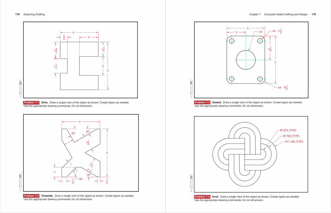
Problem 7-1 Shim. Draw a single view of the object as shown. Create layers as needed. Use the appropriate drawing commands. Do not dimension.
1
12
1 121
14
5
1211
4
60° 30°
30°45°
Problem 7-2 Template. Draw a single view of the object as shown. Create layers as needed. Use the appropriate drawing commands. Do not dimension.
Chapter 7 Computer-Aided Drafting and Design 179
4
2 ∅2 4X ∅12
122
5
4X R12
Problem 7-3 Gasket. Draw a single view of the object as shown. Create layers as needed. Use the appropriate drawing commands. Do not dimension.
R.375 (TYP)
R.750 (TYP)
R1.125 (TYP)
Problem 7-4 Knot. Draw a single view of the object as shown. Create layers as needed. Use the appropriate drawing commands. Do not dimension.
180 Exploring Drafting
121
141
1
14
34
12
1211
41112
34
14
18
14
3858
781
81381
121
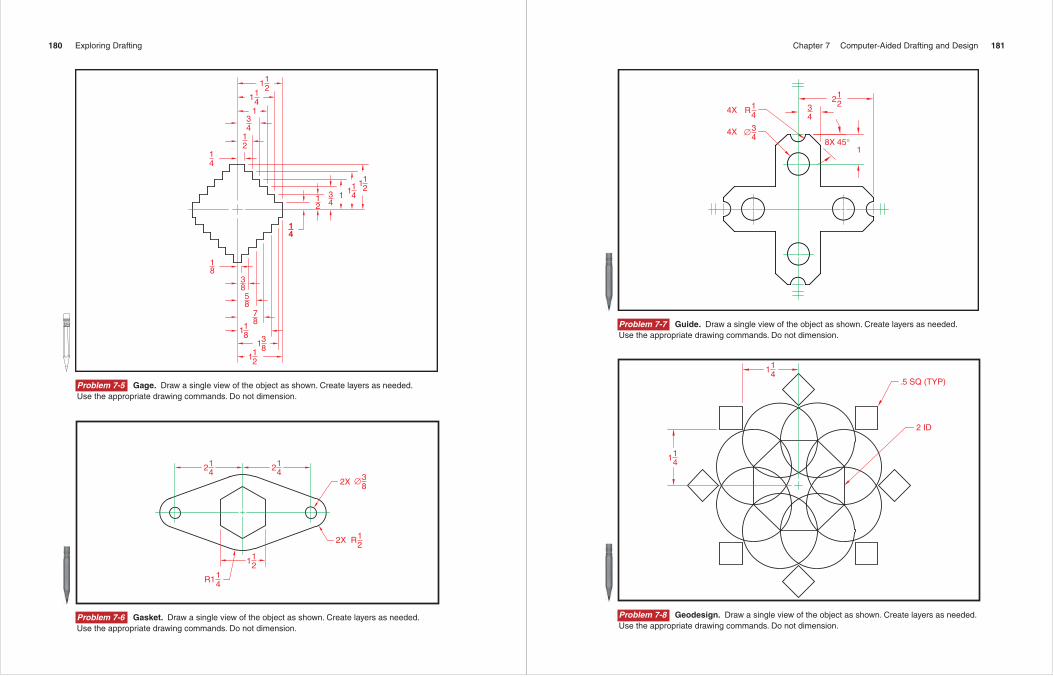
Problem 7-5 Gage. Draw a single view of the object as shown. Create layers as needed. Use the appropriate drawing commands. Do not dimension.
142 1
42
121
2X
2X
∅38
R12
14R1
Problem 7-6 Gasket. Draw a single view of the object as shown. Create layers as needed. Use the appropriate drawing commands. Do not dimension.
Chapter 7 Computer-Aided Drafting and Design 181
4X
4X
R14
∅34
122
34
8X 45°1
Problem 7-7 Guide. Draw a single view of the object as shown. Create layers as needed. Use the appropriate drawing commands. Do not dimension.
141
141
2 ID
.5 SQ (TYP)
Problem 7-8 Geodesign. Draw a single view of the object as shown. Create layers as needed. Use the appropriate drawing commands. Do not dimension.
182 Exploring Drafting
3121
112
14
10X R14 4X ∅1
4
2
14
34
341
6X R12
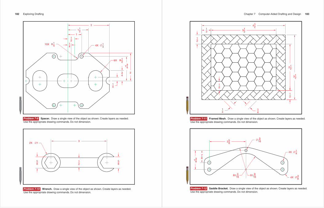
Problem 7-9 Spacer. Draw a single view of the object as shown. Create layers as needed. Use the appropriate drawing commands. Do not dimension.
12
58
58
3∅12X
Problem 7-10 Wrench. Draw a single view of the object as shown. Create layers as needed. Use the appropriate drawing commands. Do not dimension.
Chapter 7 Computer-Aided Drafting and Design 183
123
124
12
12
14
14
12
123
122
12
Problem 7-11 Framed Mesh. Draw a single view of the object as shown. Create layers as needed. Use the appropriate drawing commands. Do not dimension.
4X ∅14
4X ∅38
316∅5
82
783
81
R1 316 R1 9
16
Problem 7-12 Saddle Bracket. Draw a single view of the object as shown. Create layers as needed. Use the appropriate drawing commands. Do not dimension.
184 Exploring Drafting
ALL FILLETS R.125
2.250
1.000
.500
.750
.625
1.125 .875
R2.031
1.5001.625
1.813 1.125 .375
.438
.063
R2.031
R2.250
R1.375
4.750
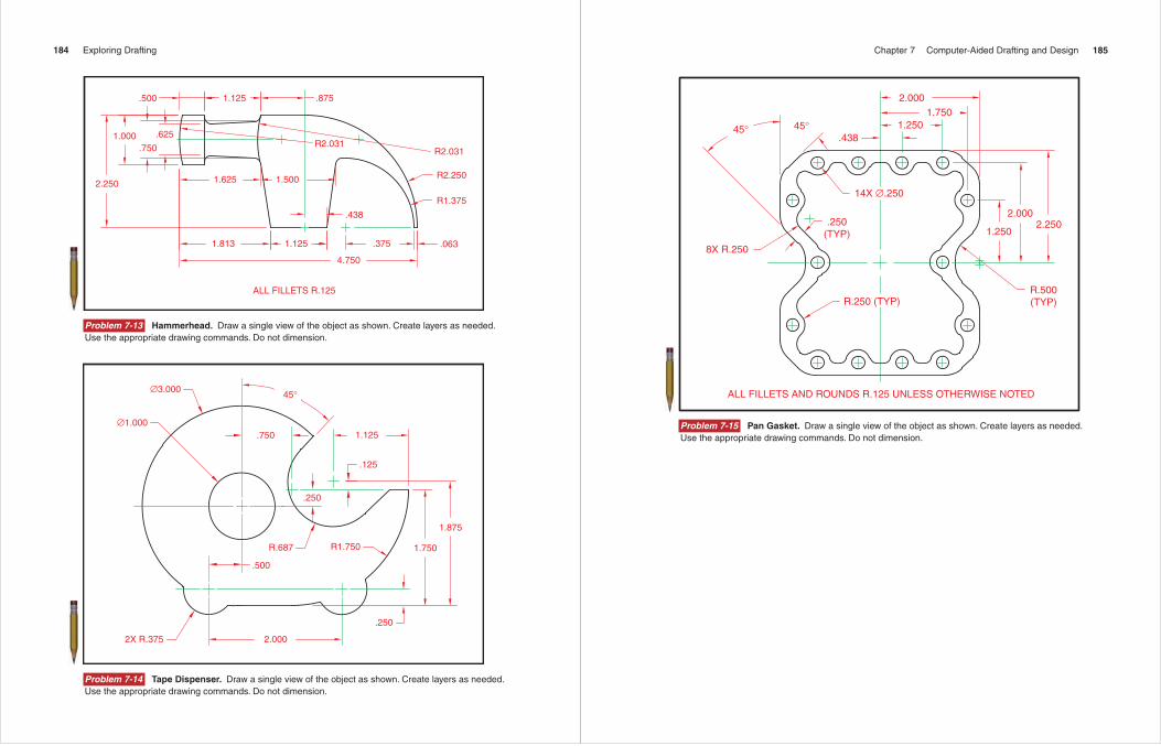
Problem 7-13 Hammerhead. Draw a single view of the object as shown. Create layers as needed. Use the appropriate drawing commands. Do not dimension.
45°∅3.000
∅1.000.750 1.125
.125
.250
R1.750R.687
.500
1.875
1.750
.250
2.0002X R.375
Problem 7-14 Tape Dispenser. Draw a single view of the object as shown. Create layers as needed. Use the appropriate drawing commands. Do not dimension.
Chapter 7 Computer-Aided Drafting and Design 185
ALL FILLETS AND ROUNDS R.125 UNLESS OTHERWISE NOTED
45° 45°.438
2.0001.750
1.250
14X ∅.250
.250(TYP)
2.000
1.2502.250
R.500(TYP)R.250 (TYP)
8X R.250
Problem 7-15 Pan Gasket. Draw a single view of the object as shown. Create layers as needed. Use the appropriate drawing commands. Do not dimension.