Objectives Discuss final project deliverables Control –Terminology –Types of controllers...
25
Objectives • Discuss final project deliverables • Control – Terminology – Types of controllers • Differences – Controls in the real world • Problems • Response time vs. stability
-
Upload
cornelius-melton -
Category
Documents
-
view
215 -
download
0
Transcript of Objectives Discuss final project deliverables Control –Terminology –Types of controllers...

Objectives
• Discuss final project deliverables
• Control – Terminology– Types of controllers
• Differences
– Controls in the real world• Problems
• Response time vs. stability

FINAL PROJECT DELIVERABLES AND GRADING
DELIVERABLES
1) PROJECT REPORT:- Project statement (introduction) 2 pages
Explain what are you designing/analyzing and why is that important On the second page clearly identify (bullet list) project outcomes - Building description (geometry) 1-3 pages
Schematics that focus on your system(s) Identify all assumptions and simplifications you introduced
- Methodology 1-3 pagesDescribe methodology (equations, schematics, …)Provide a list of assumptions used in your methodology
- Results 3-5 pagesFormatted results with commentsTables, Charts, Diagrams, … Analysis and Results discussion
- Conclusion 0.5-1 pageSummary of most important results
2) PRESENTATION:- 5 minutes (exactly)
-Power point presentation (4-6 slides)
GRADING CRITERIA:1) Analysis approach: 60%- Methodology 20%- Accuracy analysis 20%- Result analysis 20%2) Deliverables: 40%- Final report 30%- Presentations 10%

Sequence of operation for the control system design
mixing
CCOA
RA
SAHC
Adiabatichumidifier
Define the sequence of operation for:WINTER operation and:
- case when humidity is not controlled- case when humidity is precisely controlled
Solution on the whiteboard

Economizer Fresh air volume flow rate control
mixing
damper
Fresh(outdoor) air
T & RH sensors
Recirc. air
% fresh air
Minimum for ventilation
100%
TOA (hOA)
enthalpy

Economizer – cooling regime
Example of SEQUENCE OF OERATIONS:
If TOA < Tset-point open the fresh air damper the maximum position
Then, if Tindoor air < Tset-point start closing the cooling coil valve
If cooling coil valve is closed and T indoor air < Tset-point start closing the damper till you get T indoor air = T set-point Other variations are possible

Basic purpose of HVAC control
Daily, weekly, and seasonal swings make HVAC control challenging
Highly unsteady-state environment
Provide balance of reasonable comfort at minimum cost and energy
Two distinct actions:
1) Switching/Enabling: Manage availability of plant according to schedule using timers.
2) Regulation: Match plant capacity to demand

Terminology
• Sensor– Measures quantity of
interest
• Controller– Interprets sensor data
• Controlled device– Changes based on
controller outputFigure 2-13

DirectClosed Loop or Feedback
IndirectOpen Loop or Feedforward
outdoor

• Set Point – Desired sensor value
• Control Point– Current sensor value
• Error or Offset– Difference between control point and set point

Two-Position Control Systems
• Used in small, relatively simple systems
• Controlled device is on or off– It is a switch, not a valve
• Good for devices that change slowly

• Anticipator can be used to shorten response time• Control differential is also called deadband

Residential system - thermostat
• ~50 years old DDC thermostat
- Daily and weekly programming

Modulating Control Systems
Example: Heat exchanger control– Modulating (Analog) control
air
water
Cooling coil
(set point temperature)
x

Modulating Control Systems• Used in larger systems• Output can be anywhere in operating range• Three main types
– Proportional– PI– PID
Position (x)
fluid
Electric (pneumatic) motor
Vfluid = f(x) - linear or exponential function
Volume flow rate

The PID control algorithm
For our example of heating coil:
Proportional Integral Differential
time
Position (x)
constants
e(t) – difference between set point and measured value
d
TTdTKdTT
T
KTTKx d
i
)()()( measuredpointset
measuredpointset measuredpointset
Proportional(how much)
Integral(for how long)
Differential(how fast)
Position of the valve

Proportional Controllers
x is controller output
A is controller output with no error
(often A=0)
Kis proportional gain constant
e = is error (offset)
)( measuredpointset TTKAx
measuredpointset TT

Stable systemUnstable system

Issues with P Controllers
• Always have an offset
• But, require less tuning than other controllers
• Very appropriate for things that change slowly– i.e. building internal temperature

Proportional + Integral (PI)
K/Ti is integral gain
If controller is tuned properly, offset is reduced to zero
Figure 2-18a
dTTT
KTTKAx
i
)()( measuredpointset measuredpointset


Issues with PI Controllers
• Scheduling issues
• Require more tuning than for P
• But, no offset

Proportional + Integral + Derivative (PID)
• Improvement over PI because of faster response and less deviation from offset– Increases rate of error correction as errors get larger
• But– HVAC controlled devices are too slow responding– Requires setting three different gains
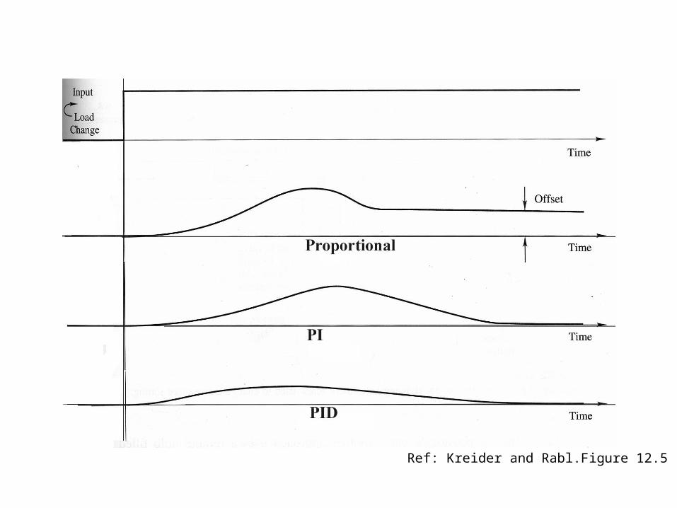
Ref: Kreider and Rabl.Figure 12.5

The control in HVAC system – only PI
dTTT
KTTKx
i
)()( measuredpointset measuredpointset
Proportional Integral
Proportionalaffect the slope
Integralaffect the shape after the first “bump”
Set point
Set point
value

The Real World
• 50% of US buildings have control problems– 90% tuning and optimization– 10% faults
• 25% energy savings from correcting control problems
• Commissioning is critically important