OBJECTIVE - Vignana Bharathi Institute of Technology · 1. LCD Based Electronic Voting Machine. 2....
94
Transcript of OBJECTIVE - Vignana Bharathi Institute of Technology · 1. LCD Based Electronic Voting Machine. 2....


OBJECTIVE:
Mission:
Practiced technique of learning to "plant a seed" in the mind of students for a specific dream topic to occur.
Vision:
The goal of Incubation Center at VBIT is to facilitate practical application of knowledge for public use. VBIT
wishes to facilitate the creation of ideas and inventions that benefit society. To this end, VBIT has developed
this Incubation centre to provide guidance and management structure to facilitate development of Knowledge.
With this Mission and Vision we started incubation centre in July 2011. Every year we conduct
the Test (On the basis of Technical Skills and Mental ability) for II Year students and we select 20 students,
they continue in this centre till their III-II semester.
In this regard we reached up to some level. We successfully developed some projects. Some are as given
below.
1. LCD Based Electronic Voting Machine.
2. RFID Based Ration card System.
3. Ultrasonic Robot.
4. Fire Alarm Systems.
5. Automatic Room Light Control and Visitor counting.
In July, 2013 The NBA Team was visited the Incubation centre and they had seen all the
working models and appreciated the students.
M. Praveen Kumar Prof. B. Brahma Reddy
Asst.Prof. ECE ECE, HOD

VIGNANA BHARATHI INSTITUTE OF TECHNOLOGY AUSHAPUR, GHATKESAR
III YEAR
2013-2014
INCUBATION PROJECT PLANNING & SCHEDULE- MATLAB
WEEK I I - HR Introduction To Signal Processing - DSP And Digital Image Processing
II - HR Introduction To MATLAB Advaned Applications using some specimens
WEEK II
I &II
HR Revising MATLAB fundamentals through programming
WEEK III I - HR MATLAB advansed instructions & practice
II - HR practice through small assignments
WEEK IV
I &II
HR Studying IEEE papers on signal processing - DSP or DIP
WEEK V I - HR
Discussion on the selected abstrct and preparation of algorithm or flow
chart of implementing the project
II - HR
Identifying the required MATLAB functions / and advaned options for
different modules / units
WEEK VI
I &II
HR Coding using the MATLAB version 7
WEEK VII
I &II
HR Coding using the MATLAB version 7
WEEK VIII
I &II
HR Coding using the MATLAB version 7
WEEK IX
I &II
HR Coding using the MATLAB version 7
WEEK X
I &II
HR prefinal Simmulation and debugging
WEEK XI
I &II
HR Documentation
WEEK XII
I &II
HR
Simmulation for final submission of result along with mini report
(documenttaion) on the project with the analysis of captured data.
The report includes the outcome attained by the student on doing the
incubation project

INCUBATION PROJECT PLANNING & SCHEDULE- EMBEDDED
WEEK I I - HR Introduction To Embedded system
II - HR Introduction To electronic components
WEEK II I - HR About Keil u vision software
II - HR basic programms and commands regulary used in programs
WEEK III I - HR Programs for interfacing devices with microcontroller
II - HR Hardware connection and soldering
WEEK IV
I &II
HR Collect the project ideas from the students and abstract
WEEK V
I &II
HR coding part for selected projects
WEEK VI
I &II
HR coding part for selected projects
WEEK
VII
I &II
HR coding part for selected projects
WEEK
VIII
I &II
HR coding part for selected projects
WEEK IX
I &II
HR Hardware connection
WEEK X
I &II
HR Hardware connection
WEEK XI
I &II
HR Documentation
WEEK
XII
I &II
HR
Final submission of project with small documentation
The report includes the outcome attained by the student on doing the
incubation project

Introduction to
Embedded System Design

Contents of Lectures
1. Introduction to Embedded System Design
2. Software for Embedded Systems
3. Real-Time Scheduling
4. Design Space Exploration
5. Performance Analysis

Topics
General Introduction to Embedded Systems
Hardware Platforms and Components
System Specialization
Application Specific Instruction Sets
• Micro Controller
• Digital Signal Processors and VLIW Programmable Hardware
ASICs
System-on-Chip

Embedded Systems
Embedded systems (ES) = information processing
systems embedded into a larger product
Examples:
Main reason for buying is not information processing

Embedded Systems
external process
human interface
embedded system sensors, actuators

Examples of Embedded Systems
Car as an integrated control-, communication and information
system.
gear box information
ABS
motor control
climate control
Examples of Embedded Systems
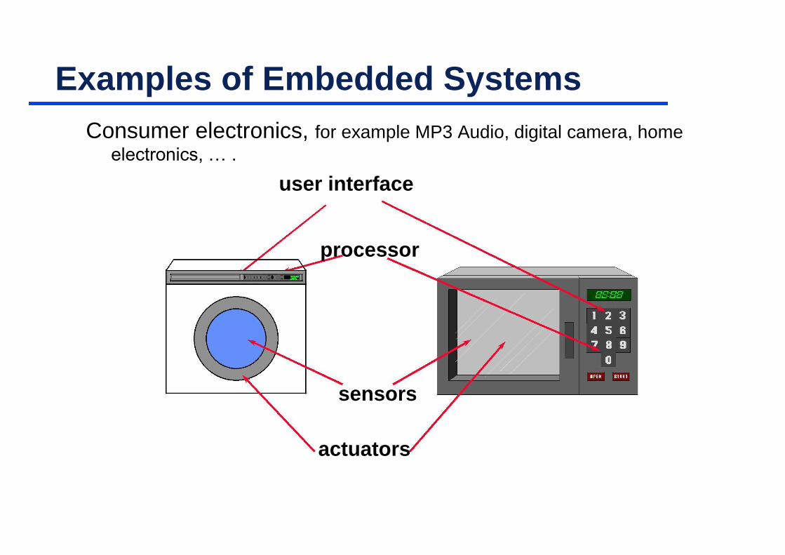
Consumer electronics, for example MP3 Audio, digital camera, home electronics, … .
user interface
processor
sensors
actuators

Examples of Embedded Systems
Production systems

Examples of Embedded Systems
Information systems, for example wireless communication (mobile phone, Wireless LAN, …), end-user equipment, router, …

Communicating Embedded Systems
Example: BTnodes (http://www.btnode.ethz.ch)
complete platform including OS
especially suited for pervasive computing applications
Sensor
Actuator
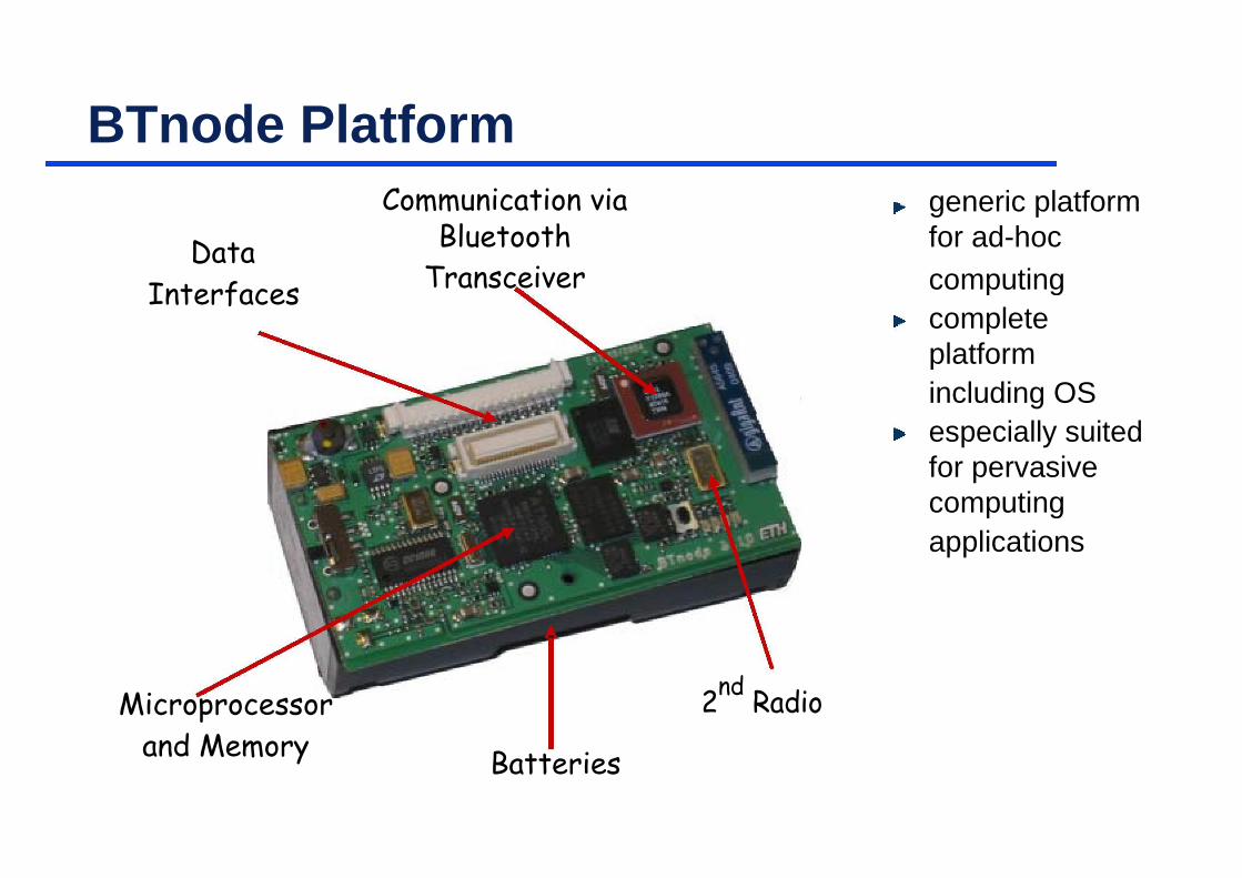
BTnode Platform
Communication via generic platform
Data Bluetooth for ad-hoc
Transceiver computing
Interfaces
complete
platform
including OS
especially suited
for pervasive
computing
applications
Microprocessor 2nd
Radio
and Memory Batteries

Communicating Embedded Systems
sensor networks (civil engineering, buildings, environmental
monitoring, traffic, emergency situations)
smart products, wearable/ubiquitous computing
MICSCS
Characteristics of Embedded Systems (1)
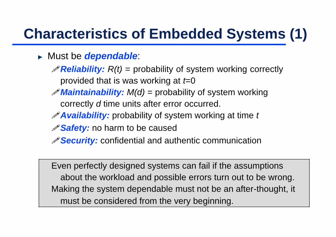
Must be dependable:
Reliability: R(t) = probability of system working correctly
provided that is was working at t=0
Maintainability: M(d) = probability of system working
correctly d time units after error occurred.
Availability: probability of system working at time t
Safety: no harm to be caused
Security: confidential and authentic communication
Even perfectly designed systems can fail if the assumptions
about the workload and possible errors turn out to be wrong.
Making the system dependable must not be an after-thought, it
must be considered from the very beginning.

Characteristics of Embedded Systems (2)
Must be efficient:
Energy efficient
Code-size efficient (especially for systems on a chip)
Run-time efficient
Weight efficient
Cost efficient
Dedicated towards a certain application: Knowledge about
behavior at design time can be used to minimize resources
and to maximize robustness.
Dedicated user interface (no mouse, keyboard and screen).

Characteristics of Embedded Systems (3)
Many ES must meet real-time constraints:
A real-time system must react to stimuli from the controlled
object (or the operator) within the time interval dictated by the
environment.
For real-time systems, right answers arriving too late (or even
too early) are wrong.
„A real-time constraint is called hard, if not meeting that
constraint could result in a catastrophe“ [Kopetz, 1997].
All other time-constraints are called soft.
A guaranteed system response has to be explained without
statistical arguments.
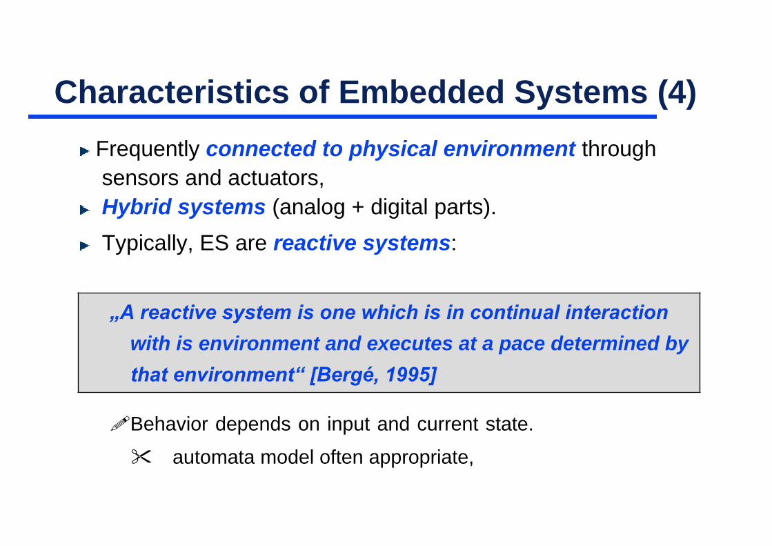
Characteristics of Embedded Systems (4)
Frequently connected to physical environment through
sensors and actuators,
Hybrid systems (analog + digital parts).
Typically, ES are reactive systems:
„A reactive system is one which is in continual interaction
with is environment and executes at a pace determined by
that environment“ [Bergé, 1995]
Behavior depends on input and current state.
automata model often appropriate,

Comparison
Embedded Systems General Purpose Computing
Few applications that are Broad class of applications.
known at design-time.
Not programmable by end Programmable by end user.
user.
Fixed run-time requirements Faster is better.
(additional computing power
not useful).
Criteria: Criteria:
• cost • cost
• power consumption • average speed
• predictability
• …

Topics
General Introduction to Embedded Systems
Hardware Platforms and Components
System Specialization
Application Specific Instruction Sets
• Micro Controller
• Digital Signal Processors and VLIW Programmable Hardware
ASICs
System-on-Chip

Embedded System Hardware
Embedded system hardware is frequently used in a loop
(„hardware in a loop“):
this course
actuators
embedded system

Typical Architecture
Wo
rl
d Peripheral Bus
Ou
tsid
e
DEBUG Port
Non-volatile memory
• EPROM, FLASH, DISK
To
• Hybrid
Microprocessor
• 4, 8, 16, 32, 4 bit bus
• CISC, RISC, DSP
• Integrated peripherals Volatile Memory
• Debug/Test Port
• DRAM, SRAM
• Caches • Hybrid
• Pipeline
• Multiprocessing Systems
System Clocks
Software • RTC circuitry
• System clocks
• Application Code • Integrated in uC
• Driver Code / BIOS • Imported/Exported
• Real Time Operating System • User Interface • Communications Protocol Stacks • C, C++, Assembly Language, ADA • Legacy Code
Custom Devices • ASIC • FPGA • PAL
Standard Devices • I/O Ports • Peripheral Controllers
Communication Devices • Ethernet • RS-232 • SCSI • Centronics • Proprietary
Microprocessor Bus • Custom • PCI • VME • PC-102

Topics
General Introduction to Embedded Systems
Hardware Platforms and Components
System Specialization
Application Specific Instruction Sets
• Micro Controller
• Digital Signal Processors and VLIW Programmable Hardware
ASICs
System-on-Chip

Implementation Alternatives
Performance
Power Efficiency
General-purpose processors
Application-specific instruction set processors (ASIPs)
• Microcontroller
• DSPs (digital signal processors) Flexibility
Programmable hardware
• FPGA (field-programmable gate arrays)
Application-specific integrated circuits (ASICs)

General-purpose Processors
High performance
Highly optimized circuits and technology
Use of parallelism
• superscalar: dynamic scheduling of instructions • super-pipelining: instruction pipelining, branch prediction,
speculation
complex memory hierarchy
Not suited for real-time applications
Execution times are highly unpredictable because of
intensive resource sharing and dynamic decisions
Properties
Good average performance for large application mix
High power consumption

Getting Started
Creating Applications with µVision®4
For 8-bit, 16-bit, and 32-bit Microcontrollers
www.keil.com

Introduction
Thank you for allowing Keil to provide you with software development tools for your embedded microcontroller applications.
This book, Getting Started, describes the µVision IDE, µVision Debugger and Analysis Tools, the
simulation, and debugging and tracing capabilities. In addition to describing the basic behavior and
basic screens of µVision, this book provides a comprehensive overview of the supported
microcontroller architecture types, their advantages and highlights, and supports you in selecting the
appropriate target device. This book incorporates hints to help you to write better code. As with any
Getting Started book, it does not cover every aspect and the many available configuration options
in detail. We encourage you to work through the examples to get familiar with µVision a nd the
components delivered.
The Keil Development Tools are designed for the professional software developer, however programmers of all levels can use them to get the most out of the embedded microcontroller architectures that are supported.
Tools developed by Keil endorse the most popular microcontrollers and are distributed in several
packages and configurations, dependent on the architecture.
MDK-ARM: Microcontroller Development Kit, for several ARM7, ARM9, and Cortex-
Mx based devices
PK166: Keil Professional Developer’s Kit, for C166, XE166, and XC2000 devices
DK251: Keil 251 Development Tools, for 251 devices
PK51: Keil 8051 Development Tools, for Classic & Extended 8051 devices
In addition to the software packages, Keil offers a variety of evaluation boards, USB-JTAG adapters, emulators, and third-party tools, which completes the range of products.
The following illustrations show the generic component blocks of µVision in conjunction with tools provided by Keil, or tools from other vendors, and the way the components relate.
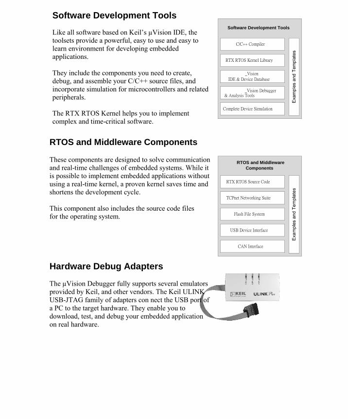
Software Development Tools Like all software based on Keil’s µVision IDE, the toolsets provide a powerful, easy to use and easy to learn environment for developing embedded applications. They include the components you need to create, debug, and assemble your C/C++ source files, and
incorporate simulation for microcontrollers and related peripherals. The RTX RTOS Kernel helps you to implement complex and time-critical software.
Software Development Tools
C/C++ Compiler
RTX RTOS Kernel Library
_Vision
IDE & Device Database
_Vision Debugger & Analysis Tools Complete Device Simulation
RTOS and Middleware Components These components are designed to solve communication
and real-time challenges of embedded systems. While it is possible to implement embedded applications without
using a real-time kernel, a proven kernel saves time and shortens the development cycle. This component also includes the source code files for the operating system.
RTOS and Middleware
Components RTX RTOS Source Code
TCPnet Networking Suite
Flash File System
USB Device Interface
CAN Interface
Hardware Debug Adapters The µVision Debugger fully supports several emulators
provided by Keil, and other vendors. The Keil ULINK
USB-JTAG family of adapters con nect the USB port of
a PC to the target hardware. They enable you to
download, test, and debug your embedded application
on real hardware.

Last-Minute Changes
As with any high-tech product, last minute changes might not be included into the printed manuals. These last-minute changes and enhancements to the software and manuals are listed in the Release Notes shipped with the product.
Licensing
Each Keil product requires activation through a license code. This code is obtained via e-mail during the registration process. There are two types of product licenses:
Single-User License is available for all Keil products. A Single-User License grants the
right to use a product on a maximum of two computers to one user. Each installation
requires a license code that is personalized for the computer on which the product is
installed. A Single-User license may be uninstalled and moved to another computer.
Floating-User License is available for many Keil products. The Floating-User license
grants the right to use that product on several computers by several different developers at
the same time. Each installation of the product requires an individual license code for
each computer on which the product is installed.
Installation
Please check the minimum hardware and software requirements that must be satisfied to ensure that your Keil development tools are installed and will function properly. Before attempting installation, verify that you have: A standard PC running Microsoft Windows XP, or Windows Vista
1GB RAM and 500 MB of available hard-disk space is recommended 1024x768 or
higher screen resolution; a mouse or other pointing device A CD-ROM drive Keil products are available on CD-ROM and via download from www.keil.com. Updates to the
related products are regularly available at www.keil.com/update.

Installation using the web download 1. Download the product from www.keil.com/demo 2. Run the downloaded executable 3. Follow the instructions displayed by the SETUP program
Installation from CD-ROM 1. Insert the CD-ROM into your CD-ROM drive. The CD-ROM browser should
start automatically. If it does not, you can run SETUP.EXE from the CD-ROM. 2. Select Install Products & Updates from the CD Browser menu 3. Follow the instructions displayed by the SETUP program
Product Folder Structure The SETUP program copies the development tools into subfolders. The base folder defaults to C:\KEIL\. The following table lists the default folders for each microcontroller architecture installation. Adjust the examples used in this manual to your preferred installation directory accordingly.
Microcontroller Architecture Folder
MDK-ARM Toolset C:\KEIL\ARM\ C166/XE166/XC2000 Toolset C:\KEIL\C166\ 8051 Toolset C:\KEIL\C51\ C251 Toolset C:\KEIL\C251\
µVision Common Files C:\KEIL\UV4\
Each toolset contains several subfolders:
Contents Subfolder
Executable Program Files \BIN\ C Include/Header Files \INC\ On-line Help Files and Release Notes \HLP\ Common/Generic Example Programs \EXAMPLES\
Example Programs for Evaluation Boards \BOARDS\

Microcontroller Architectures
The Keil µVision Integrated Development Environment (µVision IDE) supports three major microcontroller architectures and sustains the development of a wide range of applications.
8-bit (classic and extended 8051) devices include an efficient interrupt system designed for real-time performance and are found in more than 65% of all 8-bit applications. Over 1000 variants are available, with peripherals that include analog I/O, timer/counters,
PWM, serial interfaces like UART, I2C, LIN, SPI, USB, CAN, and on-chip RF
transmitter supporting low-power wireless applications. Some architecture extensions provide up to 16MB memory with an enriched 16/32-bit instruction set.
The µVision IDE supports the latest trends, like cu stom chip designs based on IP cores,
which integrate application-specific peripherals on a single chip.
16-bit (Infineon C166, XE166, XC2000) devices are tuned for optimum real-time and
interrupt performance and provide a rich set of on-chip peripherals closely coupled with
the microcontroller core. They include a Peripheral Event Controller (similar to
memory-to-memory DMA) for high-speed data collection with little or no
microcontroller overhead.
These devices are the best choice for applications requiring extremely fast responses to external events.
32-bit (ARM7 and ARM9 based) devices support complex applications, which require
greater processing power. These cores provide high-speed 32-bit arithmetic within a
4GB address space. The RISC instruction set has been extended with a Thumb mode for
high code density.
ARM7 and ARM9 devices provide separate stack spaces for high-speed context
switching enabling efficient multi-tasking operating systems. Bit-addressing and dedicated peripheral address spaces are not supported. Only two interrupt priority
levels, - Interrupt Request (IRQ) and Fast Interrupt Request (FIQ), are available.

Selecting an Architecture
Choosing the optimal device for an embedded application is a complex task. The Keil
Device Database (www.keil.com/dd) supports you in selecting the appropriate architecture and provides three different methods for searching. You can find your device
by architecture, by specifying certain characteristics of the microcontroller, or by vendor. The following sections explain the advantages of the different architectures and provide guidelines for finding the microcontroller that best fits your embedded application.
8051 Architecture Advantages
Fast I/O operations and fast access to on-chip RAM in data space
Efficient and flexible interrupt system Low-power operation 8051-based devices are typically used in small and medium sized applications that require high I/O throughput. Many devices with flexible peripherals are available, even in the smallest chip packages.
ARM7 and ARM9 Architecture Advantages Huge linear address space The 16-bit Thumb instruction set provides high code density Efficient support for all C integer data types including pointer addressing ARM7 and ARM9-based microcontrollers are used for applications with large memory demands and for applications that use PC-based algorithms.

Classic and Extended 8051 Devices
8051 devices combine cost-efficient hardware with a simple but efficient programming model that uses various memory regions to maximize code efficiency and speed-up
memory access. The following figure shows the memory layout of a classic 8051 device.
0x100
F8
0xFFFF
SFR 98 CODE
8051 Bit
0x100 SPACE 90
addressable
88 0x0000
80
0x80
0x80
DATA
DATA 128
Bytes
128 Bytes
0x0
2F
0xFFFF
8051
Bitspace 20 XDATA
4 Register
1F
Banks 0
0x0000
The 8051 architecture provides three different physical memory regions:
DATA/IDATA memory includes a 256 Bytes on-chip RAM with register banks and bit-
addressable space that is used for fast variable accessing. Some devices provide an
extended data (EDATA) space with up to 64KB.
CODE memory consists of 64KB ROM space used for program code and constants. The
Keil linker supports code banking that allows you to expand the physical memory space. In
extended variants, up to 16MB ROM space is available.
XDATA memory has a 64KB RAM space for off-chip peripheral and memory addressing.
Today, most devices provide some on-chip RAM that is mapped into XDATA.

8051 Highlights
Fast interrupt service routines with two or four priority levels and up to 32-vectored interrupts
Four register banks for minimum interrupt prolog/epilog
Bit-addressable space for efficient logical operations
128 Bytes of Special Function Register (SFR) space for tight integration of on-chip peripherals. Some devices extend the SFR space using paging.
Low-power, high-speed devices up to 100 MIPS are available
8051 Development Tool Support The Keil C51 Compiler and the Keil Linker/Locator provide optimum 8051 architecture support with the following features and C language extensions.
Interrupt functions with register bank support are written directly in C Bit
and bit-addressable variables for optimal Boolean data type support
Compile-time stack with data overlaying uses direct memory access and
gives high-speed code with little overhead compared to assembly programming
Reentrant functions for usage by multiple interrupt or task threats Generic and memory-specific pointers provide flexible memory access
Linker Code Packing gives utmost code density by reusing identical program sequences
Code and Variable Banking expand the physical memory address space Absolute Variable Locating enables peripheral access and memory sharing

8051 Memory Types A memory type prefix is used to assign a memory type to an expression with a
constant. This is necessary, for example, when an expression is used as an
address for the output command. Normally, symbolic names have an assigned memory type, so that the specification of the memory type can be omitted. The
following memory types are defined:
Prefix Memory Space
C: Code Memory (CODE) D: Internal, direct-addressable RAM memory (DATA) I: Internal, indirect-addressable RAM memory (IDATA) X: External RAM memory (XDATA) B: Bit-addressable RAM memory
P: Peripheral memory (VTREGD – 80x51 pins)
The prefix P: is a special case, since it always must be followed by a name. The
name in turn is searched for in a special symbol table that contains the register’s pin names. Example: C:0x100 Address 0x100 in CODE memory ACC Address 0xE0 in DATA memory, D: I:100 Address 0x64 in internal RAM X:0FFFFH Address 0xFFFF in external data memory B:0x7F Bit address 127 or 2FH.7 C Address 0xD7 (PSW.7), memory type B:
ARM7 and ARM9 based Microcontrollers
The ARM7 and ARM9 based microcontrollers run on a load-store RISC
architecture with 32-bit registers and fixed op-code length. The architecture
provides a linear 4GB memory address space. In contrast to the previously
mentioned 8/16-bit devices, no specific memory types are provided, since
memory addressing is performed via 32-bit pointers in microcontroller
registers. Peripheral registers are mapped directly into the linear address space.
The Thumb instruction set improves code density by providing a compressed
16-bit instruction subset. The ARM7 and ARM9 cores are easy to use, cost-effective, and support modern
object-oriented programming techniques. They include a 2-level
interrupt system with a normal interrupt (IRQ) and a fast interrupt (FIQ) vector.

To minimize interrupt overhead, typical ARM7/ARM9 microcontrollers provide
a vectored interrupt controller. The microcontroller operating modes, separate
stack spaces, and Software Interrupt (SVC) features produce efficient use of
Real-Time Operating Systems. The ARM7 and ARM9 core provides thirteen general-purpose registers (R0–
R12), the stack pointer (SP) R13, the link register (LR) R14, which holds return addresses on function calls, the program counter (PC) R15,
and a program status register (PSR). Shadow registers, available in various operating modes, are similar to register banks and reduce interrupt latency.
ARM7 and ARM9 Highlights
Linear 4 GB memory space that includes peripherals and eliminates the
need for specific memory types
Load-store architecture with efficient pointer addressing. Fast task
context switch times are achieved with multiple register load/store.
Standard (IRQ) and Fast (FIQ) interrupt. Banked microcontroller
registers on FIQ reduce register save/restore overhead.
Vectored Interrupt Controller (available in most microcontrollers)
optimizes multiple interrupt handling
Processor modes with separate interrupt stacks for predictable stack
requirements
Compact 16-bit Instruction Set (Thumb). Compared to ARM mode,
Thumb mode code is about 65% of the code size and 160% faster when
executing from a 16-bit memory system.

Code Comparison
The following short but representative code examples show the impressive
individual strengths of the different microcontroller architectures.
I/O Port Access Comparison
Source Code Description if (IO_PIN == 1) {
i++; }
Increment a value when an I/O pin is set.
8051 devices provide bit-addressable I/O Ports and instructions to
access fixed memory locations directly
C166, XE166, XC2000 devices provide bit-addressable I/O Ports and
instructions to access fixed memory locations directly
ARM7 and ARM9 devices provide indirect memory access instructions
only. However, there are no bit operations.
Cortex-Mx devices provide indirect memory access instructions only, but
allow atomic bit operations
8051 C166/XE166 and ARM7 and ARM9 Cortex-Mx Code XC2000 Code Thumb Code Thumb2 Code
sfr P0=0x80; sfr P0L=0xFF00; #define IOP *(int*)) sbit P0_0=P0^0; sbit P0_0=P0L^0;
unsigned char i; unsigned int i; unsigned int i; unsigned int i;
void main (void) { void main (void) { void main (void) { void main (void) { if (P0_0) { if (P0_0) { if (IOP & 1) { if (GPIOA->ODR) {
; JNB P0_0,?C0002 ; JNB P0_0,?C0001 ; LDR R0,=0xE0028000 ; STR R0,[R1,#0xc] ; LDR R0,[R0,#0x0] ; LDR R0,[R2,#0] ; MOV R1,#0x1 ; CBZ R0,|L1.242| ; TST R0,R1
; BEQ L_1
i++; i++; i++; i++; ; INC i ; SUB i,ONES ; LDR R0,=i ; i ; MOVS R0,#2
; LDR R1,[R0,#0x0];i ; STR R0,[R1,#0xc] ; ADD R1,#0x1 ; |L1.242| ; STR R1,[R0,#0x0];i
} } } }
; RET ; RET ; BX LR ; BX LR } } } }
6 Bytes 10 Bytes 24 Bytes 12 Bytes

Pointer Access Comparison
Source Code Description typedef struct { int x; int arr[10]; } sx; int f (sx xdata *sp, int i) {
return sp->arr[i]; }
Return a value that is part of a struct and indirectly accessed via pointer.
8051 devices provide byte arithmetic requiring several
microcontroller instructions for address calculation
C166, XE166, XC2000 devices provide efficient address arithmetic with
direct support of a large 16 MByte address space
ARM devices are extremely efficient with regard to pointer addressing
and always use the 32-bit addressing mode
In Cortex-Mx devices, any register can be used as a pointer to data
structures and arrays
8051 C166, XE166, ARM 7 and ARM9 Cortex-Mx Code XC2000 Code Thumb Code Thumb2 Code
MOV DPL,R7 MOV R4,R10 LSL R0,R1,#0x2 ADD R0,R0,R1,LSL #2 MOV DPH,R6 SHL R4,#01H ADD R0,R2,R0 LDR R0,[R0,#4] MOV A,R5 ADD R4,R8 LDR R0,[R0,#0x4]
ADD A,ACC EXTS R9,#01H
MOV R7,A MOV R4,[R4+#2]
MOV A,R4
RLC A
MOV R6,A
INC DPTR
INC DPTR
MOV A,DPL
ADD A,R7
MOV DPL,A
MOV A,DPH
ADDC A,R6
MOV DPH,A
MOVX A,@DPTR
MOV R6,A
INC DPTR
MOVX A,@DPTR
MOV R7,A
25 Bytes 14 Bytes 6 Bytes 6-Bytes

Generating Optimum Code
The C/C++ compilers provided by Keil are leaders in code generation and
produce highly efficient code. However, code generation and translation is influenced by the way the application software is written. The following hints
will help you optimize your application performance.
Coding Hints for All Architectures
Hint Description Keep interrupt functions short. Check the requirement for atomic operations.
Apply the volatile attribute on
variables that are modified by an
interrupt, hardware peripherals, or
other RTOS tasks. When possible, use automatic
variables for loops and other temporary calculations.
Well-structured interrupt functions only perform data collection
and/or time-keeping. Data processing is done in the main function
or by RTOS task functions. This reduces overhead involved with
context save/restore of interrupt functions. Atomic code is required for accessing data while using multiple RTOS threads or interrupt routines that access the memory used by the main function. Carefully check the application to determine if atomic operations are needed and verify the generated code. The various architectures have different pitfalls. For example, incrementing a variable on the 8051 and C166/XE166/XC2000 device is a single, atomic instruction, since it cannot be interrupted, whereas multiple instructions are required for an increment on ARM devices. In contrast, the 8051 requires multiple instructions to access the memory of an int variable. The volatile attribute prevents the C/C++ compiler from optimizing variable access. By default, a C/C++ Compiler may assume that a variable value will remain unchanged between several memory-read operations. This may yield incorrect application behavior in real-time applications. As part of the optimization process, the Keil C/C++ compiler attempts to maintain local variables (defined at function level) in CPU registers. Register access is the fastest type of memory access and requires the least program code.
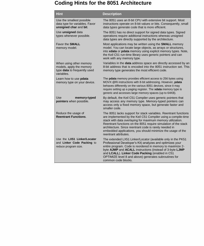
Coding Hints for the 8051 Architecture
Hint Description Use the smallest possible data type for variables. Favor unsigned char and bit. Use unsigned data
types whenever possible. Favor the SMALL
memory model. When using other memory models, apply the memory type data to frequently used variables. Learn how to use pdata
memory type on your device. Use memory-typed
pointers when possible. Reduce the usage of Reentrant Functions.
Use the LX51 Linker/Locater
and Linker Code Packing to
reduce program size.
The 8051 uses an 8-bit CPU with extensive bit support. Most instructions operate on 8-bit values or bits. Consequently, small data types generate code that is more efficient. The 8051 has no direct support for signed data types. Signed operations require additional instructions whereas unsigned data types are directly supported by the architecture. Most applications may be written using the SMALL memory model. You can locate large objects, as arrays or structures, into xdata or pdata memory using explicit memory types. Note, the Keil C51 run-time library uses generic pointers and can work with any memory type. Variables in the data address space are directly accessed by an
8-bit address that is encoded into the 8051 instruction set. This memory type generates the most efficient code. The pdata memory provides efficient access to 256 bytes using
MOVX @Ri instructions with 8-bit addressing. However, pdata
behaves differently on the various 8051 devices, since it may
require setting up a paging register. The xdata memory type is
generic and accesses large memory spaces (up to 64KB). By default, the Keil C51 Compiler uses generic pointers that may access any memory type. Memory-typed pointers can access only a fixed memory space, but generate faster and smaller code. The 8051 lacks support for stack variables. Reentrant functions are implemented by the Keil C51 Compiler using a compile-time stack with data overlaying for maximum memory utilization. Reentrant functions on the 8051 require simulation of the stack architecture. Since reentrant code is rarely needed in embedded applications, you should minimize the usage of the reentrant attributes. The extended LX51 Linker/Locator (available only in the PK51 Professional Developer’s Kit) analyzes and optimizes your entire program. Code is reordered in memory to maximize 2-byte AJMP and ACALL instructions (instead of 3-byte LJMP and LCALL). Linker Code Packing (enabled in C51 OPTIMIZE level 8 and above) generates subroutines for common code blocks.

Coding Hints for C166, XE166, XC2000 Architectures
Hint Description When possible, use 16-bit data types for automatic and parameter variables. Replace long with int data
types when possible. Use the bit data type for boolean
variables. Use the SMALL or MEDIUM
memory model when possible. When using other memory models, apply the near, idata, or sdata memory type to frequently used variables. Use the memory model HCOMPACT/HLARGE instead of COMPACT/LARGE. Use near pointers
when possible.
Parameter passing is performed in 16-bit CPU registers (many 16-bit registers are available for automatic variables). More 16-bit variables (signed/unsigned int/short) can be assigned to CPU registers. This generates code that is more efficient. Operations that use 16-bit types (like int and unsigned int)
are much more efficient than operations using long types. These CPUs have efficient bit instructions that are fully supported by the Keil C166 Compiler with the bit data type. In these memory models, the default location of a variable is in near memory, accessible through16-bit direct addresses encoded in the CPU instructions. You can locate large objects (array or struct) into huge or xhuge using explicit memory types. Variables in the near, idata, or sdata address space are
accessed through a 16-bit address that is encoded directly into a single C166/XE166/XC2000 instruction. These memory types generate the most efficient code. The memory models COMPACT and LARGE use the obsolete far memory type and have an object size limit of 16KB. The memory models HCOMACT and HLARGE use the huge memory type that feature a 64KB object size limit. Even cast operations from near to huge pointers are more optimal. Check if a near pointer is sufficient for accessing the memory, since near pointers can access variables in the near, idata, or sdata address space. Near pointers generate faster and
smaller code.

Coding Hints for the ARM7 and ARM9 Architecture
Hint Description When possible, use 32-bit data types for automatic and parameter variables. Use the Thumb
instruction set. Use __swi software
interrupt functions for atomic sequences. Enhance struct pointer
access by placing scalars at the beginning and arrays as subsequent struct members. Assign high speed interrupt code to RAM. Optimize for Size
Parameter passing is performed in 32-bit CPU registers. All ARM instructions operate on 32-bit values. In Thumb mode, all stack instructions operate only on 32-bit values. By using 32-bit data types (signed/unsigned int/long), additional data type cast operations are eliminated. Thumb mode is about 65% of the code size and 160% faster than ARM mode when executing from a 16-bit memory system. The MDK-ARM Compiler automatically inserts required ARM / Thumb interworking instructions. Via the __swi function attribute, the MDK-ARM Compiler offers a method to generate software interrupt functions directly, which cannot be interrupted by IRQ (__swi functions can be interrupted by FIQ interrupts). In contrast to other embedded architectures, ARM prevents access to the interrupt disable bits I and F in User mode. Thumb and ARM instructions encode a limited displacement for
memory access. When a struct is accessed via a pointer, scalar
variables at the beginning of a struct can be accessed directly.
Arrays always require address calculation. Consequently, it is more efficient to place scalar variables at the beginning of a
struct. Code executed from Flash ROM typically requires wait states or CPU
stalls. Code execution from RAM does not. Consequently, time critical
functions (like high-speed interrupt code) can be located in RAM
directly using the Memory Assignment feature in Options for File – Properties available via the Context Menu of that file. To optimize an application for minimal program size select under Options for Target the following toolchain:
In the dialog page Target enable Code Generation - Use Cross-Module Optimization
In the dialog page C/C++ select Optimization: Level 2 (-O2) and disable the options Optimize for Time, Split Load and Store Multiple, and One ELF Section per Function
MicroLIB The compiler offers a MicroLIB to be used for further reducing the code size of an application. MicroLIB is tailored for deeply embedded systems, but is not fully ANSI compliant. Do not use MicroLIB when execution speed is your primary goal.
Optimize for Speed To optimize an application for maximum execution speed, under Options for Target select the following toolchain: In the dialog pageTarget enable Code Generation - Use Cross-Module Optimization
In the dialog page C/C++ select Optimization: Level 3 (-O3), enable Optimize for Time, and disable Split Load and Store Multiple

Coding Hints for the Cortex-Mx Architecture
Hint Description When possible, use 32-bit
data types for automatic
and parameter variables. Optimize for Size
Parameter passing is performed in 32-bit CPU registers. All ARM instructions operate on 32-bit values. In Thumb mode, all stack instructions operate only on 32-bit values. By using 32-bit data types (signed/unsigned int/long), additional data type cast operations are eliminated. To optimize an application for minimal program size select under Options for Target the following toolchain:
In the dialog page Target enable Code Generation - Use Cross-Module Optimization
In the dialog page C/C++ select Optimization: Level 2 (-O2) and disable the options Optimize for Time, Split Load and Store Multiple, and One ELF Section per Function
MicroLIB The compiler offers a MicroLIB to be used for further reducing the code size of an application. MicroLIB is tailored for deeply embedded systems, but is not fully ANSI compliant. Do not use MicroLIB when execution speed is your primary goal.
Optimize for Speed To optimize an application for maximum execution speed, under Options for Target select the following toolchain: In the dialog pageTarget enable Code Generation - Use Cross- Module Optimization
In the dialog page C/C++ select Optimization: Level 3 (-O3), enable Optimize for Time, and disable Split Load and Store Multiple Sleep mode features Enhance struct pointer
access, by placing scalars
at the beginning and
arrays as sub-sequent
struct members.
To optimize power consumption of an application you may use the WFI instruction to send the processor into Sleep Mode until the next interrupt is received. In C programs, use the intrinsic function __wfi() to insert this instruction into your code. Thumb2 instructions encode a limited displacement for memory
access. When a struct is accessed via a pointer, scalar variables
at the beginning of a struct can be directly accessed. Arrays
always require address calculations. Therefore, it is more efficient to
place scalar variables at the beginning of a struct.
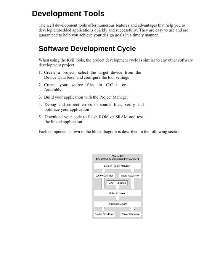
Development Tools
The Keil development tools offer numerous features and advantages that help you to develop embedded applications quickly and successfully. They are easy to use and are guaranteed to help you achieve your design goals in a timely manner.
Software Development Cycle
When using the Keil tools, the project development cycle is similar to any other software development project.
1. Create a project, select the target device from the
Device Data base, and configure the tool settings
2. Create your source files in C/C++ or Assembly
3. Build your application with the Project Manager
4. Debug and correct errors in source files, verify and
optimize your application
5. Download your code to Flash ROM or SRAM and test the linked application
Each component shown in the block diagram is described in the following section.

µVision IDE
The µVision IDE is a window-based software developm ent platform combining a robust editor, Project Manager, and Make Utility tool. µVision supports all the Keil tools
including C/C++ Compiler, Macro Assembler, Linker, Library Manager, and Object-HEX Converter. µVision helps e xpedite the development process by providing:
Device Database for selecting a device and configuring the development tools
for that particular microcontroller Project Manager to create and maintain projects
Make Utility for assembling, compiling, and linking your embedded
applications Full-featured source code editor
Template Editor that is used to insert common text sequences or header blocks
Source Browser for rapidly exploring code objects, locating and analyzing data in
your application
Function Browser for quickly navigating between functions in your
program Function Outlining for controlling the visual scope within a source file
Built-in utilities, such as Find in Files and functions for commenting and
uncommenting source code µVision Simulator and Target Debugger are fully integrated
Configuration Wizard providing graphical editing for microcontroller startup
code and configuration files
Interface to configure Software Version Control Systems and third-party utilities
Flash Programming Utilities, such as the family of Keil ULINK USB-JTAG
Adapters Dialogs for all development tool settings On-line Help and links to microcontroller data sheets and user guides

µVision Device Database
The µVision Device Database offers a convenient way to select and configure your device and
project parameters. It includes preconfigured settings, so that you can fully concentrate on your application requirements. In addition, you can add your own devices, or change existing settings.
Use the features of the Device Database to: Initialize the start up code and device settings
Load the configuration options for the assembler, compiler, and linker You can add
and change microcontroller configuration settings
µVision Debugger
The µVision Debugger is completely integrated into the µVision IDE. It provides the following features:
Disassembly of the code on C/C++ source- or assembly-level with program execution in
various stepping modes and various view modes, like assembler, text, or mixed mode
Multiple breakpoint options including access and complex breakpoints Bookmarks to
quickly find and define your critical spots
Review and modify memory, variable, and register values List the
program call tree including stack variables Review the status of on-chip microcontroller peripherals Debugging commands or C-like scripting functions
Execution Profiling to record and display the time consumed, as well as the cycles needed
for each instruction Code Coverage statistics for safety-critical application testing
Various analyzing tools to view statistics, record values of variables and peripheral I/O
signals, and to display them on a time axis
Instruction Trace capabilities to view the history of executed instructions Define
personalized screen and window layouts
The µVision Debugger offers two operating modes— Simulator Mode and Target Mode. Simulator Mode configures the µVision Debugger as a software-only product that accurately
simulates target systems including instructions and most on-chip peripherals. In this mode, you
can test your application code before any hardware is available. It gives you serious benefits for
rapid development of reliable embedded software. The Simulator Mode offers:

Software testing on your desktop with no hardware environment
Early software debugging on a functional basis improves software reliability Breakpoints that
are impossible with hardware debuggers Optimal input signals. Hardware debuggers add extra noise
Single-stepping through signal processing algorithms is possible. External signals are stopped when the microcontroller halts.
Detection of failure scenarios that would destroy real hardware peripherals
Target Mode1 connects the µVision Debugger to real hardware. Several target drivers are
available that interface to a: ULINK JTAG/OCDS Adapter that connects to on-chip debugging systems
Monitor that may be integrated with user hardware or that is available on many
evaluation boards Emulator that connects to the microcontroller pins of the target hardware
In-System Debugger that is part of the user application program and provides basic
test functions
ULINKPro Adapter a high-speed debug and trace unit connecting to on-chip debugging
systems via JTAG/SWD/SWV, and offering Cortex-M3 ETM Instruction Trace capabilities
Assembler
An assembler allows you to write programs using microcontroller instructions. It is used where

utmost speed, small code size, and exact hardware control is essential. The Keil Assemblers
translate symbolic assembler language mnemonics into executable machine code while
supporting source-level symbolic debugging. In addition, they offer powerful capabilities like
macro processing. The assembler translates assembly source files into re-locatable object modules and can optionally create listing files with symbol table and cross-reference details. Complete line
number, symbol, and type information is written to the generated object files. This information enables the debugger to display the program variables exactly. Line numbers are used for
source-level debugging with the µVision Debugger or other third-party debu gging tools. Keil assemblers support several different types of macro processors (depending on architecture):
Object-HEX Converter
The object-hex converter creates Intel HEX files from absolute object modules that have been
created by the linker. Intel HEX files are ASCII files containing a hexadecimal representation of your application program. They are loaded easily into a device program for writing to ROM,
EPROM, FLASH, or other programmable memory. Intel HEX files can be manipulated easily to include checksum or CRC data.
Linker/Locator
The linker/locator combines object modules into a single, executable program. It resolves
external and public references and assigns absolute addresses to re-locatable program segments.
The linker includes the appropriate run-time library modules automatically and processes the
object modules created by the Compiler and Assembler. You can invoke the linker from the
command line or from within the µVision IDE. To accommodate most applic ations, the default
linker directives have been chosen carefully and need no additional options. However, it is easy
to specify additional custom settings for any application.
Library Manager
The library manager creates and maintains libraries of object modules (created by the C/C++ Compiler and Assembler). Library files provide a convenient way to combine and reference a
large number of modules that may be used by the linker. The linker includes libraries to resolve external variables and functions used in applications.
Modules from libraries are extracted and added to programs only if required. Modules, containing routines that are not invoked by your program specifically, are not included in the
final output. Object modules extracted by the linker from a library are processed exactly like
other object modules.

There are a number of advantages to using libraries: security, speed, and minimized disk space are only a few. Libraries provide a vehicle for distributing large numbers of functions and
routines without distributing the original source code. For example, the ANSI C library is supplied as a set of library files. You can build library files (instead of executable programs) using the µVision Project
Manager. To do so, check the Create Library check box in the Options for Target —
Output dialog. Alternatively, you may invoke the library manager from the Command
Window.

Using µVision
The µVision IDE is, for most developers, the easies t way to create embedded system programs. This chapter describes commonly used µVision features and explains how to use them.
General Remarks and Concepts
Before we start to describe how to use µVision, som e general remarks, common to many
screens1 and to the behavior of the development tool, are presented. In our continuous effort
to deliver best-in-class development tools, supporting you in your daily work, µVision has been built to resem ble the look-and-feel of widespread applications. This approach decreases your learning curve, such that you may start to work with µVision right away.
Based on the concept of windows:
µVision windows can be re-arranged, tiled, and atta ched to other screen areas or windows respectively
It is possible to drag and drop windows, objects, and variables
A Context Menu, invoked through the right mouse button, is provided for most objects
You can use keyboard shortcuts and define your own shortcuts You can use the
abundant features of a modern editor
Menu items and Toolbar buttons are grayed out when not available in the current context
Graphical symbols are used to resemble options, to mark unsaved changes, or reveal objects not included into the project
Status Bars display context-driven information You can
associate µVision to third-party tools

To launch µVision click the µVision icon on your de sktop or select µVision from the Start Menu.
Window Layout Concepts
You can set up your working environment1 in µVision at your discretion.
Nevertheless, let us define three major screen areas. The definition will help you to understand future comments, illustrations, and instructions.
The Project Windows area is that part of the screen in which, by default, the Project
Window, Functions Window, Books Window, and Registers Window are displayed. Within the Editor Windows area, you are able to change the source code, view
performance and analysis information, and check the disassembly code. The Output Windows area provides information related to debugging, memory,
symbols, call stack, local variables, commands, browse information, and find in files
results. If, for any reason, you do not see a particular window and have tried displaying/hiding it several times, please invoke the default layout of µVision through the Window – Reset Current Layout Menu.

Positioning Windows The µVision windows may be placed onto any area of the screen, even outside of the µVision frame, or to another physical screen.
Click and hold the Title Bar1 of a window with the left mouse button
Drag the window to the preferred area, or onto the preferred control, and release the mouse button
Please note, source code files cannot be moved outside of the Editor Windows
2.
Invoke the Context Menu of the window’s Title Bar to change the docking attribute
of a window object. In some cases, you must perform this action before you can drag
and drop the window.
µVision displays docking helper controls 3, emphasizing the area where the window
will be attached. The new docking area is represented by the section highlighted in blue. Snap the window to the Multiple Document Interface (MDI) or to a Windows area by moving the mouse over the preferred control.
1 You may click the page/object name to drag and drop the object.
2 Source code files stay in the Text Editor’s window .
3 Controls indicate the area of the new window position. The new position is highlighted.

µVision Modes µVision operates in two modes: Build Mode and Debug Mode. Screen settings, Toolbar
settings, and project options are stored in the context of the mode. The File Toolbar is enabled
in all modes, while the Debug Toolbar and Build Toolbar display in their respective mode
only. Buttons, icons, and menus are enabled if relevant for a specific mode. The standard working mode is Build Mode. In this mode you write your application, configure
the project, set preferences, select the target hardware and the device; you will compile, link,
and assemble the programs, correct the errors, and set general settings valid for the entire
application. In Debug Mode, you can also change some general options and edit source code files, but these
changes will only be effective after you have switched back to Build Mode, and rebuild your
application. Changes to debug settings are effective immediately.
Menus
The Menu bar provides access to most µVision commands inclu ding file operations, editor
operations, project maintenance, development tool settings, program debugging, window
selection and manipulation, and on-line help.
File Menu The File Menu includes commands that open, save, print, and close source files. The Device
Database and License Manager dialogs are accessed from this menu.
Edit Menu The Edit Menu includes commands for editing the source code; undo, redo, cut, copy, paste,
and indentation, bookmark functions, various find and replace commands, source outlining
functions, and advanced editor functions. Editor configuration settings are also accessed from this menu.

View Menu The View Menu includes commands to display/hide
a variety of windows. You can also enable/disable
the Status Bar. The Periodic Window Update option is useful in
Debug Mode to force the screens to periodically
refresh. If this option has not been selected, you can
manually update the screens via the Toolbox.
Project Menu The Project Menu includes commands to open, save,
and close project files. You can Export your project
to a previous version of µVision, Manage project
components, or Build the project. In addition, you can
set Options for the project, group, and file. You can
manage multiple projects through the Multi-Project Workspace… Menu.
Flash Menu The Flash Menu includes commands you can use
to configure, erase, and program Flash memory
for your embedded target system.

Debug Menu The Debug Menu includes commands that start and stop a
debug session, reset the CPU, run and halt the program, and
single-step in high-level and assembly code. In addition,
commands are available to manage breakpoints, view RTOS
Kernel information, and invoke execution profiling. You can modify the memory map and manage debugger functions and
settings.
Tools Menu Configure and run PC-Lint or set up your own tool shortcuts to
third party utilities.
SVCS Menu The SVCS Menu allows you to configure and integrate your
project development with third-party version control systems.
Help Menu The Help Menu includes commands to start the on-line help system, to list information about on-chip peripherals, to access
the knowledgebase, to contact the Technical Support team, to
check for product updates, and to display product version
information.

Peripherals Menu The Peripherals Menu includes dialogs to display and change
on-chip peripheral settings. The content of this menu is
tailored to show the specific microcontroller options selected
for your application. Dialogs are typically available for System
Configuration, Interrupts, UARTs, I2C, Timer/Counters,
General Purpose I/O, CAN, Pulse-Width Modulators, Real-
Time Clocks, and Watchdog Timers. This menu is active in Debug Mode only.
Window Menu The Window Menu includes commands
to split, select, and close various
windows in the Text Editor. In addition, you can define your own screen
layouts through the Debug Restore Views… dialog, and
switch back and forth between the screen
layouts you defined. Restore the default layout through Reset View to Defaults at any time. Currently open
source code windows are listed at the bottom of the Window Menu.

Toolbars and Toolbar Icons
The µVision IDE incorporates several Toolbars with buttons for the most commonly used commands.
The File Toolbar contains buttons for commands used to edit source files, to configure µVision,
and to set the project specific options
The Build Toolbar contains buttons for commands used to build the project The Debug
Toolbar contains buttons for commands used in the debugger The File Toolbar is always available, while the Build Toolbar and Debug Toolbar will display
in their context. In both modes, Build Mode and Debug Mode, you have the option to display or
hide the applicable Toolbars.
File Toolbar
New File – opens an empty text window Open File – dialog to
open an existing file
Save File – saves the contents of the current file Save All – saves
changes in all open files
Cut – deletes the selected text and copies it to th e clipboard Copy – copies the
currently selected text to the cl ipboard
Paste – inserts text from the clipboard to the curr ent cursor position Undo changes –
removes prior changes in an edit win dow
Redo changes – restores the last change that was un done
Navigate Backwards – moves cursor to its former bac kward position

Navigate Forwards – moves cursor to its former forw ard position Bookmark –
sets or removes a bookmark at cursor pos ition
Previous Bookmark – moves the cursor to the bookmar k previous to the current cursor position Next Bookmark – moves cursor to the bookmark ahead of the current cursor position Clear All Bookmarks – removes bookmarks in the curr ent document Indent – moves
the lines of the highlighted text on e tab stop to the right Unindent – moves all
highlighted text lines one tab stop to the left
Set Comment – converts the selected code/text to co mment lines Remove Comment
– converts the selected text lines b ack to code lines
Find in Files – searches for text in files; results shown in an extra window Find – searches for specified text in current docum ent
Incremental Find – finds expression as you type Debug Session –
starts/stops debugging
Breakpoint – sets or removes a breakpoint at cursor position Disable Breakpoint –
disables the breakpoint at cur sor position Disable All Breakpoints – disables all
breakpoints in all documents Kill All Breakpoints – removes all breakpoints from
all documents
Project Window – dropdown to enable/disable project related windows Configure
– dialog to configure your editor, shortc uts, keywords, …

Build Toolbar
Translate/Compile – compiles or assembles the file in the current edit window
Build – builds and links those files of the project that have changed or whose dependencies have changed
Rebuild – re-compiles, re-assembles, and re-links a ll files of the project
Batch Build – re-builds the application based on ba tch instructions. This feature is active in a Multi-Project environment only.
Stop Build – halts the build process
Download – downloads your application to the target system flash
Target – drop-down box to select your target system (in the Toolbar example above: Simulator)
Target Options – dialog to define tool and target s ettings. Set device, target, compiler, linker, assembler, and debug options here. You can also configure your flash device from here.
File Extensions, Environments, and Books – dialog t o configure targets, groups, default folders, file extensions, and additional books
Manage Multi-Project Workspace – dialog to add or r emove individual projects or programs to or from your multi-project container
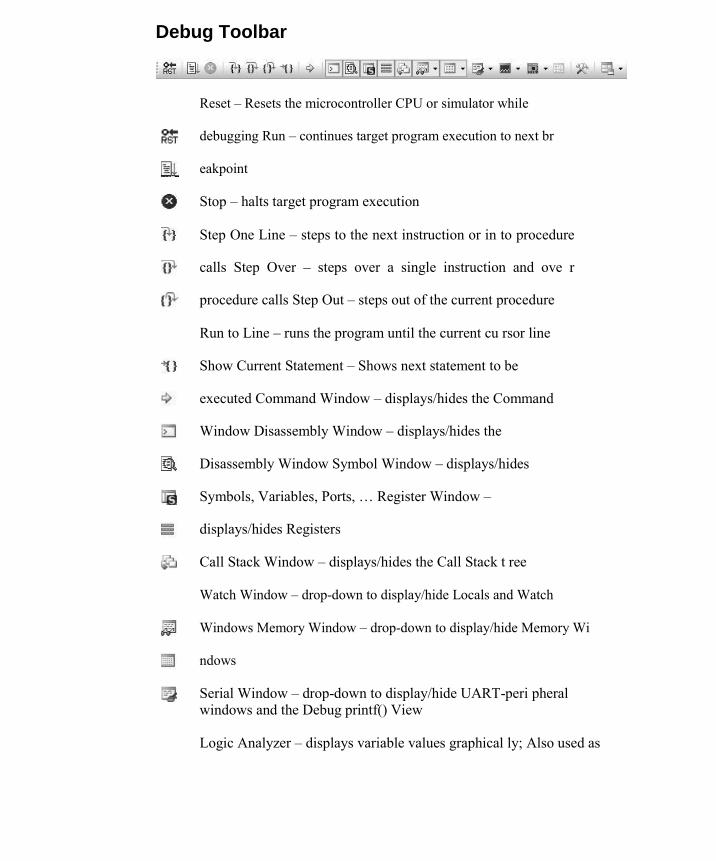
Debug Toolbar
Reset – Resets the microcontroller CPU or simulator while
debugging Run – continues target program execution to next br
eakpoint
Stop – halts target program execution
Step One Line – steps to the next instruction or in to procedure
calls Step Over – steps over a single instruction and ove r
procedure calls Step Out – steps out of the current procedure
Run to Line – runs the program until the current cu rsor line
Show Current Statement – Shows next statement to be
executed Command Window – displays/hides the Command
Window Disassembly Window – displays/hides the
Disassembly Window Symbol Window – displays/hides
Symbols, Variables, Ports, … Register Window –
displays/hides Registers
Call Stack Window – displays/hides the Call Stack t ree
Watch Window – drop-down to display/hide Locals and Watch
Windows Memory Window – drop-down to display/hide Memory Wi
ndows
Serial Window – drop-down to display/hide UART-peri pheral windows and the Debug printf() View
Logic Analyzer – displays variable values graphical ly; Also used as

a drop-down to display/hide the Performance Analyzer and Code Coverage Window.
Performance Analyzer – displays, in graphical form, the time consumed by
modules and functions as well as the number of function calls
Code Coverage – dialog to view code execution stati stics in a different way than with the Performance Analyzer
System Viewer – view the values of your Peripheral Registers
Instruction Trace – displays/hides the Instruction Trace Window
Toolbox – shows/hides the Toolbox dialog. Dependin g on your target system, various options are available.
Debug Restore Views – drop-down to select the prefe rred window layout while debugging
Additional Icons
Print – opens the printer dialog
Books – opens the Books Window in the Project Works pace
Functions – opens the Functions Window in the Proje ct Workspace
Templates – opens the Templates Window in the Proje ct Workspace
Source Browser – opens the Source Browser Window in the
Output Workspace. Use this feature to find definitions or
occurrences of variables, functions, modules, and macros in your
code.
µVision Help – opens the µVision Help Browser
File – Source file; you can modify these files; def ault options are
used
File – Source file; you can modify these files; fil e options have been changed and are different from the default options
File or Module – header files; normally, included a utomatically into the project; options cannot be set for these file types

Folder or Group – expanded – icon identifying an ex panded folder or group;
options correspond to the default settings Folder or group – expanded – icon identifying an ex panded folder or group;
with changed options that are different from the default settings Folder or group – collapsed – with options correspo nding to default settings Folder or group – collapsed – with options changed and different form default settings Lock – freezes the content of a window; prevents th at window from refreshing periodically; You cannot manually change the content of that
window. Unlock – unfreezes the content of a window; allows that window to refresh periodically. You can manually change the content of that
window. Insert – creates or adds an item or object to a lis t
Delete - removes an item or object from a list
Move Up - moves an item or object higher up in the list
Move Down - moves an item or object down in the list
Peripheral SFR (Peripheral Registers, Special Function Register) Simulator VTREG (Virtual Register) Application, Container Variable Parameter Function
Creating Embedded Programs
µVision is a Windows application that encapsulates the Keil microcontroller development tools as well as several third-party utilities. µVision provides everything you need to start creating embedded programs quickly. µVision includes an advanced editor, project manage r, and make utility, which work together to ease your development efforts, decreases the learning curve, and helps you to get started with creating embedded applications quickly. There are several tasks involved in creating a new embedded project:
Creating a Project File Using the Project Windows Creating Source Files Adding Source Files to the Project Using Targets, Groups, and Files Setting Target Options, Groups Options, and File Options Configuring the Startup Code Building the Project Creating a HEX File Working with Multi-Projects
The section provides a step-by-step tutorial that shows you how to create an embedded project using the µVision IDE.
Creating a Project File
Creating a new µVision project requires just three steps: 1. Select the Project Folder and Project Filename 2. Select the Target Microcontroller 3. Copy the Startup Code to the Project Folder

Selecting the Folder and Project Name To create a new project file, select the Project – New Project… Menu. This
opens a standard dialog that prompts you for the new project file name. It is
good practice to use a separate folder for each project. You may use the
Create New Folder button in this dialog to create a new empty folder. Select the preferred folder and enter the file name for the new project. µVision creates a new, empty project file with the specified name. The project contains a default target and file group name, which you can view on the Project
Window.
Selecting the Target Microcontroller After you have
selected the folder
and decided upon a
file name for the
project, µVision asks
you to choose a
target
microcontroller. This
step is very
important, since µVision customizes
the tool settings,
peripherals, and
dialogs for that
particular device.
The Select Device1,2
dialog box lists all the devices from the µVision Device Database. You may invoke this screen through the Project – Select Device for
Target… Menu in order to change target later.
Copying the Startup Code All embedded programs require some kind of microcontroller initialization or
startup code1,2
that is dependent of the tool chain and hardware you will use. It is required to specify the starting configuration of your hardware. All Keil tools include chip-specific
startup code for most of the devices
listed in the Device Database. Copy

the startup code to your project folder
and modify it there only. µVision
automatically displays a dialog to copy the startup code into your project folder. Answer this question with YES.
µVision will copy the startup code to your project folder and adds the startup
file to the project. The startup code files are delivered with embedded comments used by the configuration wizard to provide you with a GUI interface for startup
configuration.
Using the Project Windows
Once you have created a project file successfully, the Project Window shows the targets, groups, and files of your project. By default, the target name is set to Target 1, while the group’s name is Source Group 1. The file containing the startup code is added to the source group. Any file, the startup file included, may be moved to any other group you may define in future. The Books Window, also part of the Project
Windows, provides the Keil product manuals, data
sheets, and programmer’s guides for the selected
microcontroller. Double-click a book to open it.
1 The startup code’s default settings provide a good starting point for most single-chip applications. However, changes to the startup code may be required.
2 Library and add-on projects need no startup code.
Right-click the Books Window to open its Context Menu. Choose Manage Books… , to invoke the Components, Environments and
Books1 dialog to modify
the settings of the exiting manuals or add your own manuals to the list of books.
Later, while developing the program, you may use the
Functions Window and Templates Window as well.
Creating Source Files
Use the button on the File Toolbar or the select the File – New… Menu
to create a new source file This action opens an empty Editor Window to enter your source code. µVision
enables color syntax highlighting based on the file extension (after you have
saved the file). To use this feature immediately, save the empty file with the
desired extension prior to starting coding.
Save the new source file using the button on the File Toolbar or use the File – Save Menu

Adding Source Files to the Project
After you have created and saved your source file,
add it to the project. Files existing in the project
folder, but not included in the current project
structure, will not be compiled. Right-click a file group in the Project Window and select Add Files to Group
from the Context Menu. Then, select the source
file or source files to be added. A self-explanatory window will guide you through the steps of adding a file.
Using Targets, Groups, and Files
The µVision’s very flexible project management stru cture allows you to create more than one Target for the same project. A Target is a defined set of build options that assemble, compile, and link the included files
in a specific way for a specific platform. Multiple file groups may be added to a target and multiple files may be attached to the same file group. You can define multiple targets for the same project as well. You should customize the name of targets and groups to match your application structure and internal naming conventions. It is a good practice to create a separate file group for microcontroller configuration files.
Use the Components, Environment, and Books… dialog to manage your Targets, Groups, and Files configuration

To change the name of a Target, Group, or File you may either:
Double-click the desired item, or
Highlight the item and press F2
Change the name and click the OK button. Changes will be
visible in the other windows as soon as this dialog has been
closed.
Insert - create a new target or group
Delete - remove a target, group, or source file from the project
Move Up - move a target, group, or source file up the list
Move Down - move a target, group, or source file down the list
Instead of using the Move Up or Move Down buttons, you may drag and drop the source files within the Project Window to re-arrange the order of the files.
Setting Target Options
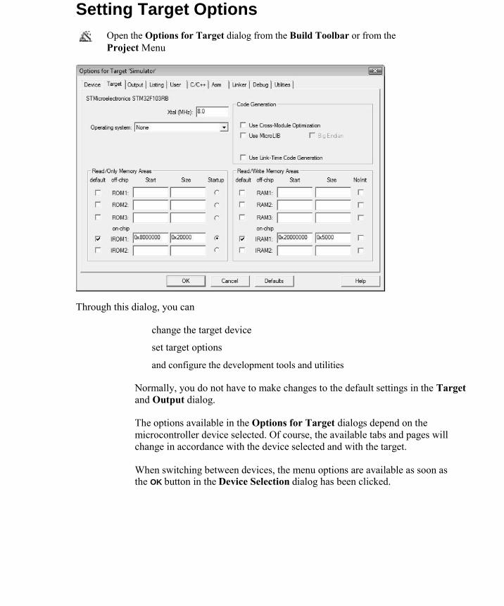
Open the Options for Target dialog from the Build Toolbar or from the Project Menu
Through this dialog, you can
change the target device set target options and configure the development tools and utilities
Normally, you do not have to make changes to the default settings in the Target
and Output dialog. The options available in the Options for Target dialogs depend on the
microcontroller device selected. Of course, the available tabs and pages will
change in accordance with the device selected and with the target. When switching between devices, the menu options are available as soon as the OK button in the Device Selection dialog has been clicked.

The following table lists the project options that are configurable on each page of the Target Options dialog.
Dialog Page Description
Device Selects the target device from the Device Database Target Specifies the hardware settings of your target system Output Specifies the output folders and output files generated Listing Specifies the listing folders and listing files generated User Allows you to start user programs before and after the build process C/C++ Sets project-wide C/C++ Compiler options Asm Sets project-wide Assembler options Linker Sets project-wide Linker options. Linker options are typically required to
configure the physical memory of the target system and locate memory classes and sections. Debug Sets Debugger options, including whether to use hardware or simulation
Utilities Configures utilities for Flash programming
Setting Group and File Options
In µVision, properties of objects and options can b e set at the group level and on individual files. Use this powerful feature to set options for files and groups that need a configuration different from the default settings. To do so, open the Project Window:
Invoke the Context Menu of a file group and select Options for Group to
specify the properties, compiler options, and assembler options for that file
group
Invoke the Context Menu of a source file and select Options for File to
specify the properties, compiler, or assembler options for that file Treat Target options similar to general options. They are valid for the entire
project and for that target. Some options can be defined at the group level and on
individual files. File-level options will supersede group-level options, which in
turn, supersede the options set at the target level.
Red dots on the icon’s left side are an indication that the options of that item differ from the general target options
Configuring the Startup Code
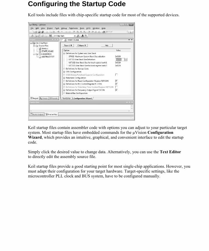
Keil tools include files with chip-specific startup code for most of the supported devices.
Keil startup files contain assembler code with options you can adjust to your particular target
system. Most startup files have embedded commands for the µVision Configuration
Wizard, which provides an intuitive, graphical, and convenient interface to edit the startup
code. Simply click the desired value to change data. Alternatively, you can use the Text Editor to directly edit the assembly source file. Keil startup files provide a good starting point for most single-chip applications. However, you must adapt their configuration for your target hardware. Target-specific settings, like the microcontroller PLL clock and BUS system, have to be configured manually.
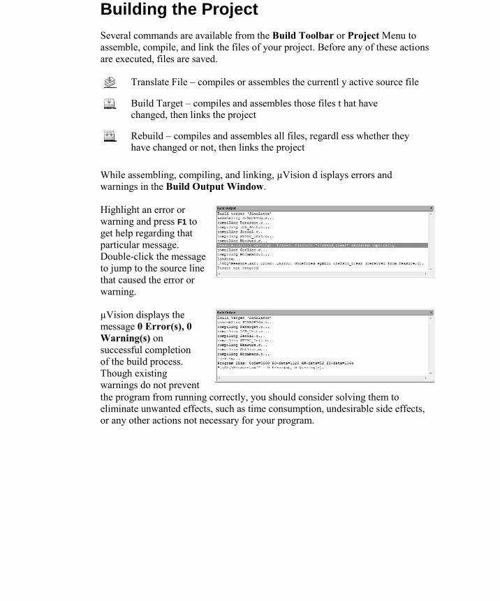
Building the Project Several commands are available from the Build Toolbar or Project Menu to
assemble, compile, and link the files of your project. Before any of these actions
are executed, files are saved.
Translate File – compiles or assembles the currentl y active source file
Build Target – compiles and assembles those files t hat have changed, then links the project
Rebuild – compiles and assembles all files, regardl ess whether they have changed or not, then links the project
While assembling, compiling, and linking, µVision d isplays errors and warnings in the Build Output Window. Highlight an error or
warning and press F1 to
get help regarding that
particular message.
Double-click the message
to jump to the source line
that caused the error or
warning. µVision displays the
message 0 Error(s), 0
Warning(s) on
successful completion
of the build process.
Though existing
warnings do not prevent the program from running correctly, you should consider solving them to eliminate unwanted effects, such as time consumption, undesirable side effects, or any other actions not necessary for your program.

Creating a HEX File Check the Create HEX File box under Options for Target — Output , and µVision will
automatically create a HEX file during the build process. Select the desired HEX format through the drop-down control to generate formatted HEX files,
which are required on some Flash programming utilities.
Debugging
The µVision Debugger can be configured as a Simulat or1 or as a Target
Debugger2. Go to the Debug tab of the Options for Target dialog to switch
between the two debug modes and to configure each mode.
The Simulator is a software-only product that simulates most features of a
microcontroller without the need for target hardware. By using the Simulator, you can
test and debug your embedded application before any target hardware or evaluation
board is available. µVision also simula tes a wide variety of peripherals including the
serial port, external I/O, timers, and interrupts. Peripheral simulation capabilities vary
depending on the device you have selected.
The Target Debugger is a hybrid product that combines µVision with a hardware
debugger interfacing to your target system. The following debug devices are
supported:
JTAG/OCDS Adapters that connect to on-chip debugging systems like the ARM
Embedded ICE
Target Monitors that are integrated with user hardware and that are
available on many evaluation boards
Emulators that connect to the MCU pins of the target hardware
In-System Debuggers that are part of the user application program and
provide basic test functions
Third-party tool developers may use the Keil Advanced GDI to interface µVision to their own hardware debuggers.
No matter whether you choose to debug with the Simulator or with a target debugger, the µVision IDE implements a single user interface that is easy to learn and master.
1 The Simulator offers more capabilities and features than those available when debugging on target hardware. The Simulator runs entirely on the PC and is not limited by hardware restrictions.
2 Programs run on your target hardware. You can debug your application with restrictions.

To debug programs using the Simulator, check Use Simulator on the
left side of the Debug
dialog. To debug programs
running on target
hardware, check Use <Hardware Debugger> on the
right side of the Debug dialog. In addition to selecting whether you debug with the Simulator or Target Debugger, the Debug dialog provides a great variety of debugger configuration options.
Control Description
Settings Opens the configuration dialog for the simulation driver or the
Advanced GDI target driver
Load Application at Startup Loads the application program when you start the debugger
Limit Speed to Real-Time Limits simulation speed to real-time such that the simulation
does not run faster than the target hardware
Run to main() Halts program execution at the main C function. When not set,
the program will stop at an implicit breakpoint ahead of the main
function
Initialization File Specifies a command script file which is read and executed
when you start the debugger, before program execution is
started
Breakpoints Restores breakpoint settings from the prior debug session
Watchpoints & PA Restores watchpoints and Performance Analyzer settings from
Memory Display the prior debug session
Restores memory display settings from the prior debug session
Toolbox Restores toolbox buttons from the prior debug session
CPU DLL Specifies the instruction set DLL for the simulator. Do not
modify this setting.
Driver DLL Specifies the instruction set DLL for the target debugger. Do not
modify this setting.
Dialog DLL Specifies the peripheral dialog DLL for the simulator or target
debugger. Do not modify this setting.

Simulation
µVision simulates up to 4 GB of memory from which s pecific areas can be mapped for reading, writing, executing, or a combination of these. In most cases,
µVision can deduce the correct memory map from the program object module. Any illegal memory access is automatically trapped and reported. A number of device-specific simulation capabilities are possible with µVision. When you select a microcontroller from the Device Database, µVision configures the Simulator accordingly and selects the appropriate instruction set, timing, and peripherals. The µVision Simulator:
Runs programs using the ARM7, ARM9, Thumb, Thumb2, 8051, C166/XE166/XC2000 instruction sets
Is cycle-accurate and correctly simulates instructions and on-chip peripheral timing, where possible
Simulates on-chip peripherals of many 8051, C166/XE166/XC2000, ARM7, ARM9, and Cortex-Mx devices
Can provide external stimulus using the debugger C script language
Starting a Debug Session
When you start a debug session, µVision loads the a pplication, executes the startup code, and, if configured, stops at the main C function. When program
execution stops, µVision opens a Text Editor window, with the current source code line highlighted, and a Disassembly Window, showing the disassembled
code.
Use the Start/Stop Debug Session command of the Debug Toolbar to
start or stop a debugging session. Screen layouts are restored when
entering and saved automatically when closing the Debugger.
The current instruction or high-level statement (the one executed on the next instruction cycle) is marked with a yellow arrow. Each time you step, the arrow moves to reflect the new current line or instruction.
This screenshot below shows some of the key windows available in Debug Mode.


Debug Mode Most editor features are also available while debugging. The Find command can be used to locate
source text and source code can be modified. Much of the Debugger interface is identical to the
Text Editor interface. However, in Debug Mode the following additional features, menus, and windows are
available: Debug Menu and Debug Toolbar – for accessing debug commands
Peripherals Menu – is populated with peripheral dialogs used to monitor the environment
Command Window – for executing debug commands and for showing debugger
messages
Disassembly Window – provides access to source code disassembly Registers Window
– to view and change values in registers directly Call Stack Window – to examine the
programs call tree Memory, Serial, and Watch Windows – to monitor the application
Performance Analyzer Window – to fine tune the application for performance Code Coverage Window – to inspect the code for safety-critical systems
Logic Analyzer Window – to study signals and variables in a graphical fo rm Execution
Profiler – to examine the execution time and number of call s
Instruction Trace Window – to follow execution of the program sequence Symbol
Window – to locate program objects comfortably
System Viewer – to supervise peripheral registers
Multiple Debug Restore Layouts – can be defined to switch between preferred
window arrangements Besides the disabled build commands, you may not:
Modify the project structure Change tool
parameters

Using the Command Window
Generic compile and
debug information are
displayed here while
stepping through the code.
Additional notifications
are provided if, for
example, memory areas
cannot be accessed. Enter
debugger commands on
the Command Line of the Command Window. Valid instructions will rise on its status bar with hints to
parameters and parameter options. Insert expressions to view or modify the
content of registers, variables, and memory areas. You can invoke debugger
script functions as well. We strongly advise you to make use of the detailed on-
line help information, by pressing F1. Describing the many options available is
beyond the scope of this book.
Using the Disassembly Window
Configure this window
by invoking its Context
Menu. You can use this
window to view the time
an instruction needs to
execute or to display the
number of calls. You can
also set or remove
breakpoints and
bookmarks. View a trace history of previously executed instructions through the View – Trace – View Trace Records Menu. To view a history trace, enable the
option View – Trace – Enable Trace Recording . If the Disassembly Window is the active window, single-stepping works at the
assembler instruction level rather than at the program source level.

Executing Code µVision provides several ways to run your programs. You can
Instruct the program to run directly to the main C function. Set this option in the Debug tab of the Options for Target dialog.
Select debugger commands from the Debug Menu or the Debug
Toolbar Enter debugger commands in the Command Window Execute debugger commands from an initialization file
Starting the Program
Select the Run command
from the Debug Toolbar or Debug Menu or type GO in the Command Window to run the program
Stopping the Program
Select Stop from
the Debug Toolbar or from the Debug Menu or press the Esc key while in the Command Window
Resetting the CPU
Select Reset from
the Debug Toolbar or from the Debug – Reset CPU Menu or type RESET in the Command Window to reset the simulated CPU

Single-Stepping
To step through the program and into function calls use the Step
command from the Debug Toolbar or Debug Menu. Alternatively,
you enter TSTEP in the Command Window, or press F11.
To step through the program and over function calls use the Step Over
command from the Debug Toolbar or Debug Menu. Enter PSTEP in
the Command Window, or press F10.
To step out of the current function use the Step Out command from the Debug Toolbar or Debug Menu. Enter OSTEP in the Command
Window, or press Ctrl+F11.
Examining and Modifying Memory
µVision provides various ways to observer and chang e program and data
memory. Several windows display memory contents in useful formats.
Viewing Register Contents The Registers Window shows the content of
microcontroller registers. To change the content of a
register double-click on the value of the register.
You may also press F2 to edit the selected value.

Memory Window Monitor memory areas through four distinct Memory Windows.
Open the Memory Window from the Debug Toolbar or the View – Memory – Memory[ x] Menu
The Context Menu allows you to select the
output format. Enter an expression in the Address field to
monitor the desired area or object. To change the
content of an address, double-click on the value
and modify it. To update the Memory Window periodically,
enable View – Periodic Window Update . Use
Update Windows in the Toolbox to refresh the
windows manually.
To stop the Memory Window from refreshing, uncheck View – Periodic
Window Update, or use the Lock button to get a snapshot of the window.
You may compare values of the same address space by taking snapshots of
the same section in a second Memory Window.
Memory Commands The following memory commands can be entered in the Command Window.
Command Description
ASM Displays or sets the current assembly address and allows you to enter
assembly instructions. When instructions are entered, the resulting op-
code is stored in code memory. You may use the in-line assembler to
correct mistakes or to make temporary changes to the target program.
DISPLAY Displays a range of memory in the Memory Window (if it is open) or in the
Command Window. Memory areas are displayed in HEX and in ASCII.
ENTER Allows you to change the contents of memory starting at a specified
address
EVALUATE Calculates the specified expression and outputs the result in decimal,
UNASSEMBLE octal, HEX, and ASCII format
Disassembles code memory and displays it in the Disassembly Window

PROJECT LIST:
1. 3D LED CUBE
2. PERSISTENCE OF VISION CONTROL USING ARDUINO
3. ACCELEROMETER BASED HAND GESTURE CONTROLLED ROBOT
4. FACE FEATURE DETECTION
5. AUDIO COMMUNICATION USING MICROWAVE BENCH
6. BASIC INTRCOM CIRCUIT
7. WIRELESS POWER TRANSFER
8. GENERATION OF ELECTRICITY THROUGH SPEED BREAKER MECHANISM
9. AUTOMATIC DOORBELL WITH OBJECT DETECTION
10. AUTOMATIC COLLEGE ALARM BELL SYSTEM

3D LED CUBE
ABSTRACT
Our project consists of building a 3 dimensional LED array that will be able to display
various graphics through the concept of persistence of vision. The array will also be sensitive to
motion in three directions, allowing it to focus certain graphics to a targeted audience through
motion detection. There will be several options for display including non-directional animations
and direction focused graphics.
The software for this project uses a simple timer interrupt model to control the
multiplexed LED matrix. Each time an interrupt occurs, the current layer is turned off, data for
the next layer is written to the LED drivers, and the next layer is then turned on. Interrupts must
occur quickly enough that all layers are refreshed at > 30Hz to avoid flicker. The algorithms to
generate patterns run in between interrupts. Any number of patterns can be added and the cube
will loop through all of them indefinitely.
The LED cube is made up from 27 LEDs arranged into 3 layers of 9 LEDs each. All LED
anodes of a layer are connected and all cathode of a row are connected. This allows multiplexing
with LED driver ICs, so instead of requiring 27 connections it requires one to each of the five
layers and 9 to each LED in a layer making a total of 9.
ROHIT VEDULA - 10P61A0472
P.SAI PRAVEEN REDDY- 10P61A0477
B.VINAY KUMAR - 10P61A04B5

PERSISTENCE OF VISION CONTROL USING ARDUINO
ABSTRACT:
In current era in which energy is the main factor in designing all the applications,
maximum and efficient use of the energy is very important. A Persistence of Vision (POV)
display has many advantages over a traditional CRT, LCD or LED display, like power savings,
less complexity, easy configuration, attractiveness etc. To overcome the drawback of old
processor we have decided to implement the same display atop a new and advanced
microcontroller, the Arduino-Uno. This platform brings with it newer coding and a different
understanding of peripherals. ARDUINO INTERFACE BOARDS provide us with a low-cost,
easy-to use technology to create the project. We also aim to build the newer display to work with
modern forms of interfaces. To accomplish this, we will be interfacing the display with an
Android device.
The core phenomenon on which the entire project is based is the Persistence of vision.
Persistence of vision is the phenomenon pertaining to the human eye by which an afterimage is
thought to persist for approximately one twenty-fifth of a second on the retina. The way this
phenomenon of persistence of vision works is based on the belief that human perception of
motion (brain centered) is the result of persistence of vision (eye centered). People still identify
motion at rates as low as ten frames per second or slower (as in a flipbook). The flicker caused
by the shutter of a film projector is distracting below the 16-frame threshold.
A two dimensional POV display is often accomplished by means of rapidly moving a
single row of LEDs along a linear or circular path. The effect is that the image is perceived as a
whole by the viewer as long as the entire path is completed during the visual persistence time of
the human eye as shown below. A further effect is often to give the illusion of the image floating
in mid-air. A 3 dimensional POV display is often constructed using a 2D grid of LEDs which is
swept or rotated through a volume. POV display devices can be used in combination with long
camera exposures to produce light.
ROHIT VEDULA - 10P61A0472
P.SAI PRAVEEN REDDY- 10P61A0477
B.VINAY KUMAR - 10P61A04B5

ACCELEROMETER BASED HAND GESTURE CONTROLLED
ROBOT
ABSTRACT
In many application of controlling robotic gadget it becomes quite hard and complicated when there
comes the part of controlling it with remote or many different switches. Mostly in military application,
industrial robotics, construction vehicles in civil side, medical application for surgery. In this field it is
quite complicated to control the robot or particular machine with remote or switches, sometime the
operator may get confused in the switches and button itself, so a new concept is introduced to control the
machine with the movement of hand which will simultaneously control the movement of robot.
A Gesture Controlled robot is a kind of robot which can be controlled by your hand gestures not by old
buttons.You just need to wear a small transmitting device in your hand which included an acceleration
meter.This will transmit an appropriate command to the robot so that it can do whatever we want. The
transmitting device included a ADC for analog to digital conversion and an encoder IC(HT12E) which is
use to encode the four bit data and then it will transmit by an RF Transmitter module.At the receiving end
an RF Receiver module receive's the encoded data and decode it by and decoder IC(HT12D). This data is
then processed by a microcontroller and finally our motor driver to control the motor's. In this project we
are using AVR controller and Accelerometer.
ROHIT VEDULA(10P61A0472)
VINAY KUMAR(10P61A04B5)
SAI PRAVEEN REDDY(10P61A0477)

FACE FEATURE DETECTION
The aim of this project is to develop an algorithm that detects human facial features like the
mouth, nose and eyes in a full frontal face image. We adapted a multi-step process in order to
achieve the goal. To detect the face region a skin-color segmentation method was used. A fast,
reliable automatic human face and facial feature detection is one of the initial and most important
steps of face analysis and face recognition systems for the purpose of localizing and extracting
the face region from the background.
This project presents a Viola Jones Face Detection Method that instantly detects faces in
still images or video frames. This work is distinguished by three key contributions. The first is
the introduction of a new image representation called the integral image which allows the
features used by our detector to be computed very quickly. The second is a learning algorithm,
based on AdaBoost, which selects a small number of critical visual features from a larger set and
yields extremely efficient classifiers. The third contribution is a method for combining
increasingly more complex classifiers in a cascade which allows background regions of the
image to be quickly discarded while spending more computation on promising object-like
regions.
Applications are Law enforcement and justice solutions, Childbase protection,
Identification solutions, Homeland defence, Immigration, Access control, Scene analysis and
surveillance solutions.
By
G.Preethi (11P61A0464)
D.Vaishnavi(11P61A04B0)
III ECE-B, VBIT

Audio Communication using Microwave bench
Abstract
Here we are trying to establish audio communication through microwave bench. The low signal
audio signal is amplified by using audio amplifier circuits and is given as input to the microwave
bench. At the other end of the microwave bench the output is again a low power signal and hence
is again amplified using some power amplifier circuits. The speaker acts as a load at the output
and hence voice can be heard.
Group Members:
1) M.Srikar Phani Kumar – 11P61A0497
2) K.Prashanth – 11P61A0461
3) D.Rubeena – 11P61A0478
Basic Intercom Circuit
Abstract
An intercom is a stand-alone voice communication system for use within a certain range that is
either within a college or an office etc. Our circuit helps in establishing a one way intercom
service using basic components of electronics like transistors, resistors and capacitors. 2
intercom circuits are connected and connections are established between them and the output can
be verified in the speakers provided which act as load to the circuits.
Group Members:
1) T V S R Prasad – 11P61A04B5
2) N Ramakrishna Rao – 11P61A0468
3) D. Sri Vidya – 11P61A0499

WIRELESS POWER TRANSFER
ABSTRACT
The main objective of this project is to develop a device for wireless power transfer. The concept
of wireless power transfer was realized by Nikolas tesla. Wireless power transfer can make a
remarkable change in the field of the electrical engineering which eliminates the use
conventional copper cables and current carrying wires.
One of the major issue in power system is the losses occurs during the transmission and
distribution of electrical power. As the demand increases day by day, the power generation
increases and the power loss is also increased. The major amount of power loss occurs during
transmission and distribution. The percentage of loss of power during transmission and
distribution is approximated as 26%. The main reason for power loss during transmission and
distribution is the resistance of wires used for grid. The efficiency of power transmission can be
improved to certain level by using high strength composite over head conductors and
underground cables that use high temperature super conductor. But, the transmission is still
inefficient.
The circuitry used in this project is base on slayer circuit. A slayer exciter is basically a small
solid state tesla coil, usually a one transistor design. A Slayer Exciter is an air-cored transformer
that steps up a very low DC voltage to a very high AC voltage. This creates an electromagnetic
field around the coil that is capable of lighting up fluorescent and neon light bulbs. It is fairly
similar to a Tesla Coil.
Moreover this technique can be used in number of applications, like to charge a mobile phone,
iPod, laptop battery, propeller clock wirelessly. And also this kind of charging provides a far
lower risk of electrical shock as it would be galvanically isolated.
This concept is an Emerging Technology, and in future the distance of power transfer can be
enhanced as the research across the world is still going on.
Shaik Mohammed Salim 11P61A0485
M Shashanka 11P61A0490
K Srivathsa 11P61A0498
J Venkat Reddy 11P61A04B4

Generation of Electricity through Speed Breaker Mechanism
Abstract :
This paper is presenting the study of electricity generation through the speed breaker mechanism.
For obtaining the electricity through the speed breaker mechanism a prototype model is
developed and studied.
Findings from this research work is discussed in this paper, the generator used here is permanent
magnet D.C. generator. The generator voltage is 12 Volt D.C. This D.C. voltage is stored to the
lead 12-volt battery. The battery is connected to the inverter. The inverter is used to convert 2
volt D.C. to the 230 volt A.C. voltage is used to activate the streetlights, traffic signals etc. By
increasing the capacity of the battery and the inverter circuit the power rating is increased.
The principle of the electric power generation using speed breaker mechanism is very simple.
It is based on the same Principle as in the case of electricity generation in case of hydroelectric
power plant, thermal electric power plant, nuclear power plant, geothermal energy, wind energy,
tidal energy etc. In all of the above power plant mechanical energy is converted into electrical
energy. In this setup also mechanical energy is converted into electrical power using a D.C.
generator. Here the vertical motion of the top of the speed breaker is converted into the rotational
motion, which in turn rotates the generator and generates electricity.
By 11P61A0477
(Roja.P) 11P61A0482
(G.Sainath) 11P61A0491
(Sirisha) ECE-B

AUTOMATIC DOORBELL WITH OBJECT DETECTION
ABSTRACT:
We all have a doorbell at our homes. When a visitor comes to our house, he searches for the
doorbell switch and then rings it to let us know his presence. If the who came to our house
cannot find the doorbell or else if the person is so short that he cannot reach the doorbell. In such
cases, it is better if we use an automatic doorbell which rings as soon as a person arrives at our
place. There are no more hassles. The person who comes to our house need not search for the
doorbell and press it any more. If we install this automatic doorbell using object detection circuit,
the circuit will automatically sense the presence of the person and it rings the doorbell.This
circuit operates using a pair of ultrasonic transmitter and receiver modules which are used to
detect the person and then if the person is detected, the doorbell is automatically turned ON
when the person is in-front of the door. The circuit works as a panic alarm and could be
applicable in many cases. The circuit operates using a pair of ultrasonic transmitter and receiver
modules which are used to detect the person. When the person is detected (the person is in the
front door), the doorbell is automatically turned ON.Instead of placing a buzzer circuit at the
output, we may also place a bulb by connecting the NORMALLY OPERATED pin of the relay
directly to the bulb and the COMMON pin of the relay is first connected to the power supply and
then it is given to the bulb. In this automatic doorbell using object detection circuit, the circuit
will automatically sense the presence of the person and it rings the doorbell.
Mounika Raj 11P61A0450
Bindu Bharadwaj 11P61A0429
Abhilash Reddy 11P61A0402

AUTOMATIC COLLEGE ALARM BELL SYSTEM
ABSTRACT
Embedded Based Automatic College Bell System project is developed for the users to
control Bell system in companies or institutions automatically. All the bell timings and durations
are predefined and set in the microcontroller.
The user can set the timings using a key pad. A LCD display is used to display the
timings. The timings set by the user are stored in the microcontroller.
At the particular time, signal is generated in the microcontroller and sent through the
output port. The electronic circuit receives the signal and drives a corresponding relay. The relay
is used as a switch to operate the Bell. As soon as the duration is over, the signal is stopped and
waiting for the next set time.
This system is mainly used in Schools, Colleges and other companies where Bell system
is implemented. There is no need of a person managing the bell timings.
This project is very useful in schools ,colleges and eductional/academic institutions for
automation of periodic class bell.This bell rings only at preprogrammed things.As the DS1307
Real Time Clock chip is used,entire thhe calendar can be programmed in to the
microcontroller.User can program the bell to ring the bell from morning to evening at pre defined
timmings and not to ring in after school hours and on Sundays and second Saturdays.
Switc hes are provided for entering the required timings. LCD is provided to display the
alarm times and current time. DS1307 is interfaced to the microcontroller for real timing
performance.
External EPROM is used in this project to store the set timings. Data stored remains in
the memory even after power failure, as the memory ensures reading of the latest saved settings
by microcontroller. It can retain data for more than ten years.
GROUP:
11p61a0474,
11p61a0484.