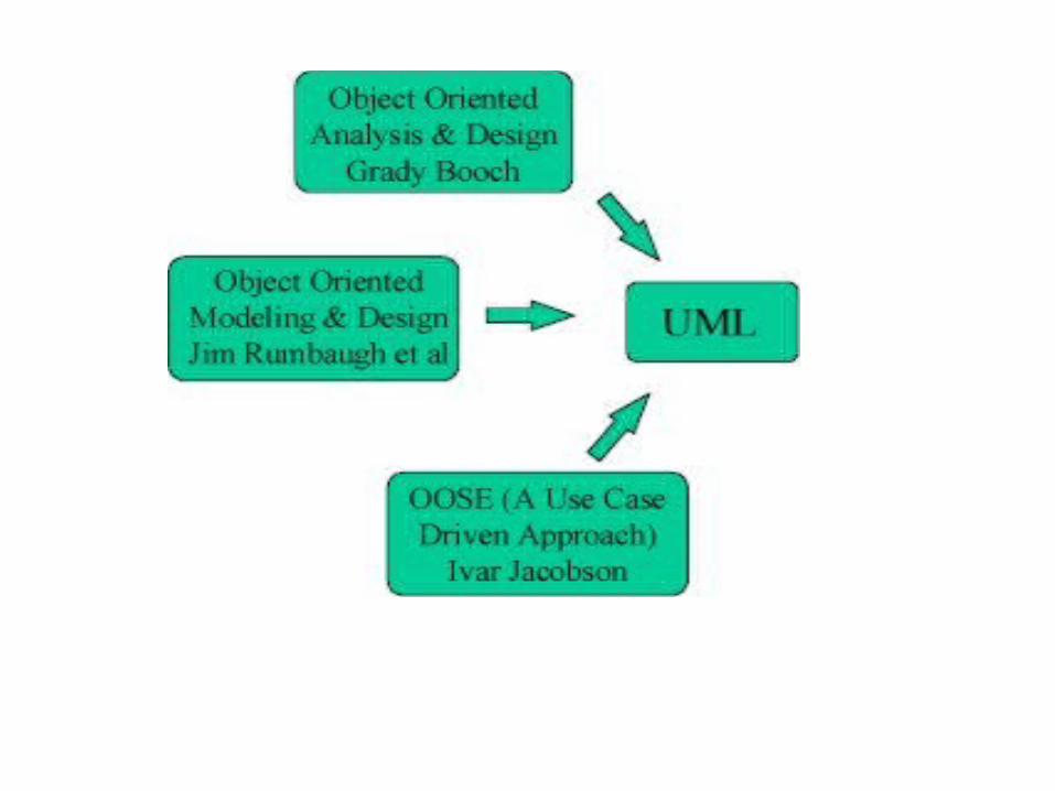
Object-OrientedMethodologies –The Rumbaugh et al. OMT –The Booch methodology – Jacobson's...
72
Object-OrientedMethodologies –The Rumbaugh et al. OMT –The Booch methodology – Jacobson's methodologies 1
-
Upload
vernon-joseph -
Category
Documents
-
view
263 -
download
1
Transcript of Object-OrientedMethodologies –The Rumbaugh et al. OMT –The Booch methodology – Jacobson's...

Object-OrientedMethodologies
–The Rumbaugh et al. OMT –The Booch methodology – Jacobson's methodologies
1

Methodology
•A methodology is explained as thescience of methods.
•A method is a set of procedures in which a specific goal is approached step by step
2
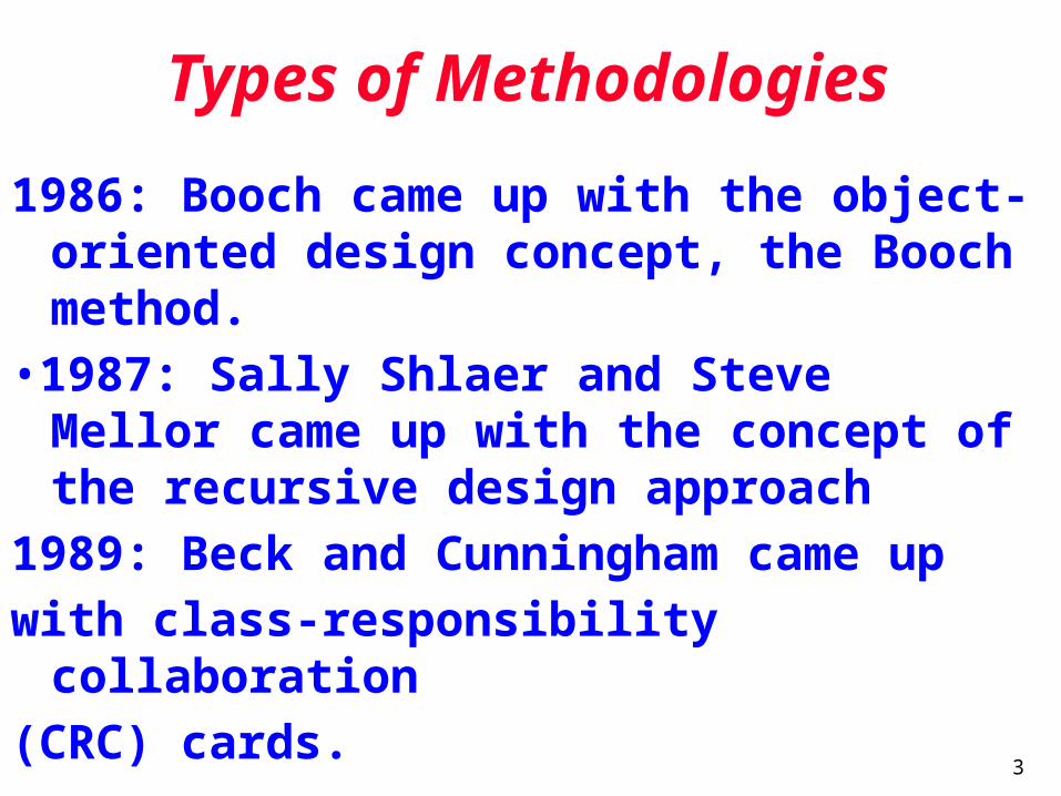
Types of Methodologies
1986: Booch came up with the object-oriented design concept, the Booch method.
•1987: Sally Shlaer and Steve Mellor came up with the concept of the recursive design approach
1989: Beck and Cunningham came upwith class-responsibility collaboration(CRC) cards.
3
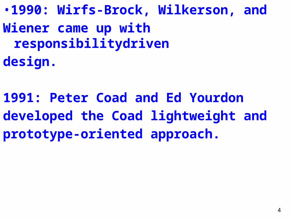
•1990: Wirfs-Brock, Wilkerson, andWiener came up with
responsibilitydrivendesign.
1991: Peter Coad and Ed Yourdondeveloped the Coad lightweight andprototype-oriented approach.
4
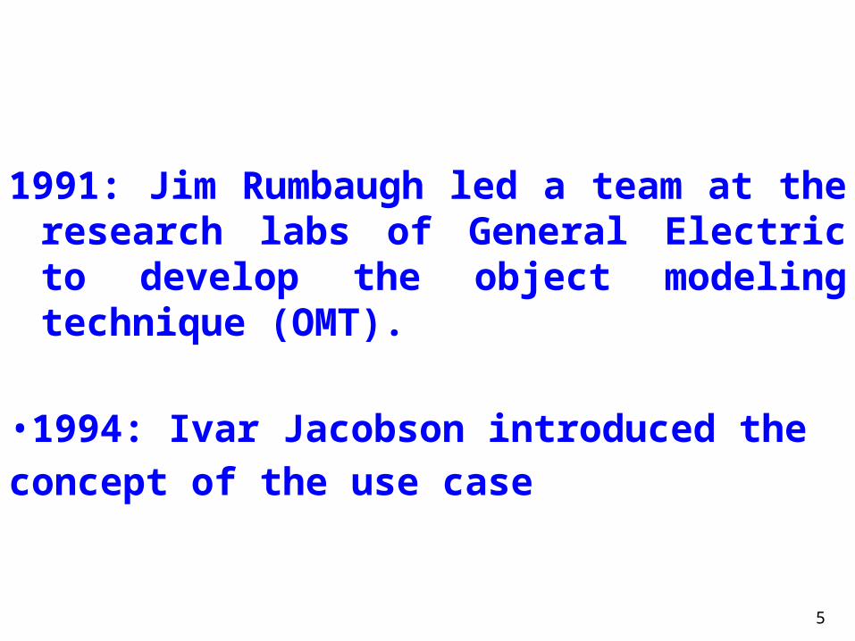
1991: Jim Rumbaugh led a team at the research labs of General Electric to develop the object modeling technique (OMT).
•1994: Ivar Jacobson introduced theconcept of the use case
5

Many methodologies are available to
choose from for system development, some of them are discussed below :-
6

Rumbaugh et. al.’s ObjectModeling Technique (OMT)
OMT describes a method for the analysis, design, and implementation of a system using an object-oriented technique
7
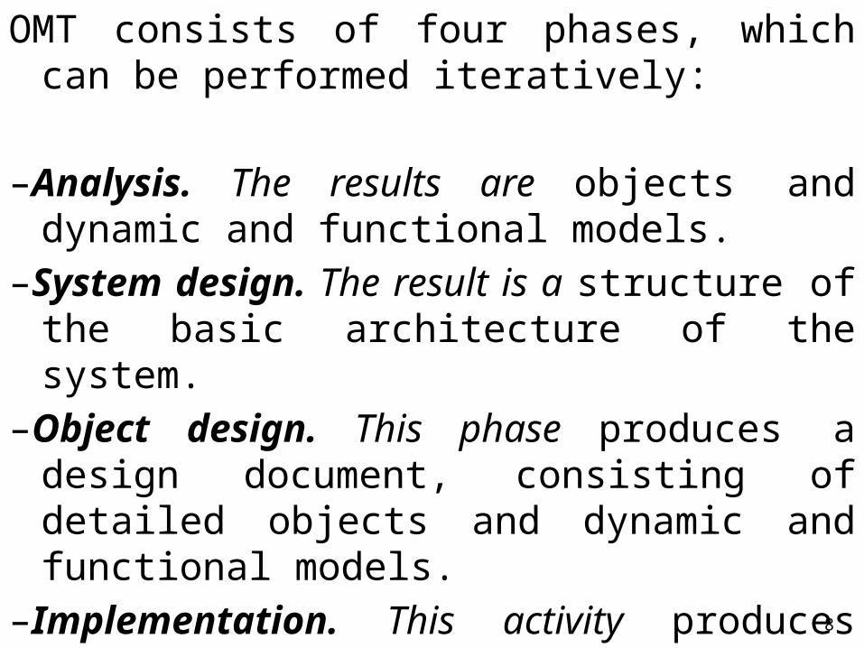
OMT consists of four phases, which can be performed iteratively:
–Analysis. The results are objects and dynamic and functional models.
–System design. The result is a structure of the basic architecture of the system.
–Object design. This phase produces a design document, consisting of detailed objects and dynamic and functional models.
–Implementation. This activity produces reusable, extendible, and robust code 8

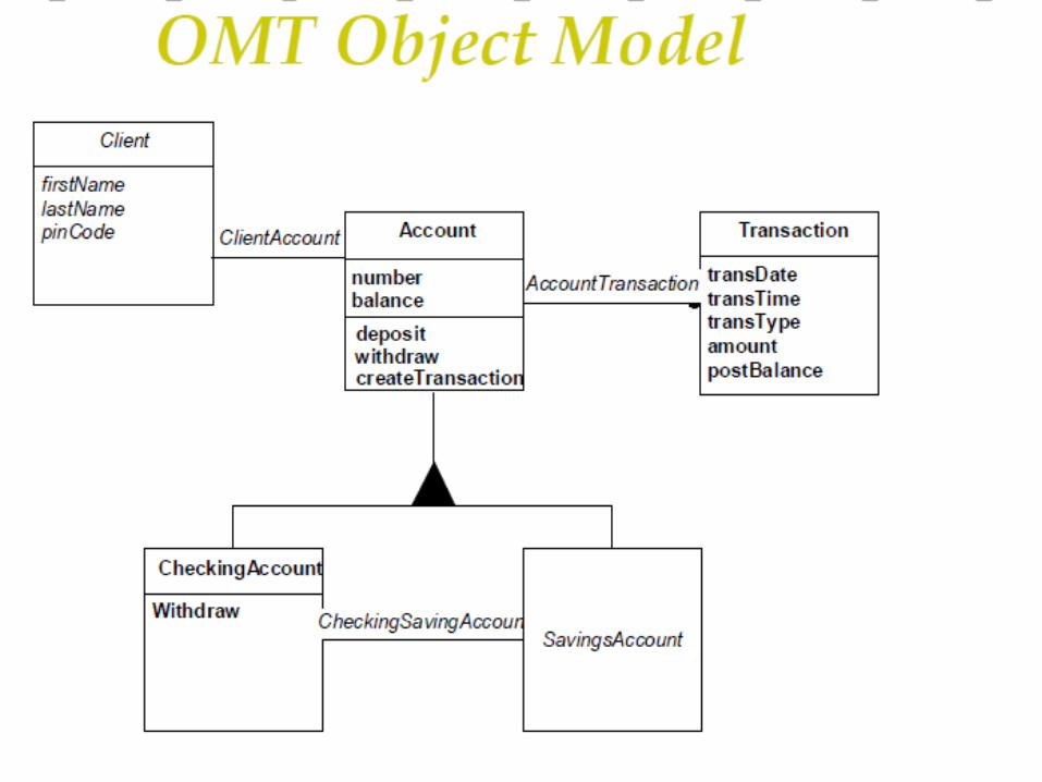
OMT separates modeling intothree different parts:
1. An object model, presented by the object model and the data dictionary.
2. A dynamic model, presented by the state diagrams and event flow diagrams.
3. A functional model, presented by data flow and constraints.
9
10

11

12

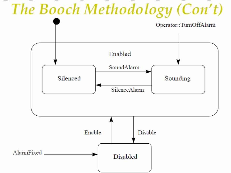
The Booch Methodology
• The Booch methodology covers the analysis and design phases of systems development.
• Booch sometimes is criticized for his large set of symbols.
13
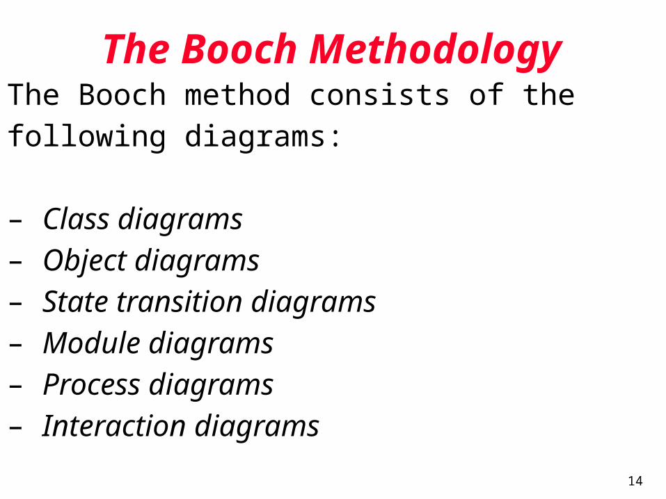
The Booch MethodologyThe Booch method consists of thefollowing diagrams:
– Class diagrams– Object diagrams– State transition diagrams– Module diagrams– Process diagrams– Interaction diagrams
14

15
16
The Booch methodology Prescribes
– A macro development process
– A micro development process
17

The Macro Development Process•The macro development process consists
of the following steps:
– 1. Conceptualization– 2. Analysis and development of the
model. – 3. Design or create the system
architecture.– 4. Evolution or implementation.– 5. Maintenance.
18

The micro development process consists of the following steps:
– 1. Identify classes and objects.– 2. Identify class and object semantics.– 3. Identify class and object relationships.– 4. Identify class and object interfacesand implementation
19
The Jacobson et al. Methodologies
The Jacobson et al. Methodologies (e.g., OOBE, OOSE, and Objectory) cover the entire life cycle and stress traceability between the different phases
20
Use cases are scenarios for understanding system requirements.
•A use case is an interaction betweenusers and a system.
•The use-case model captures the goal of the user and the responsibility of the system to its users.
21

22

23

24
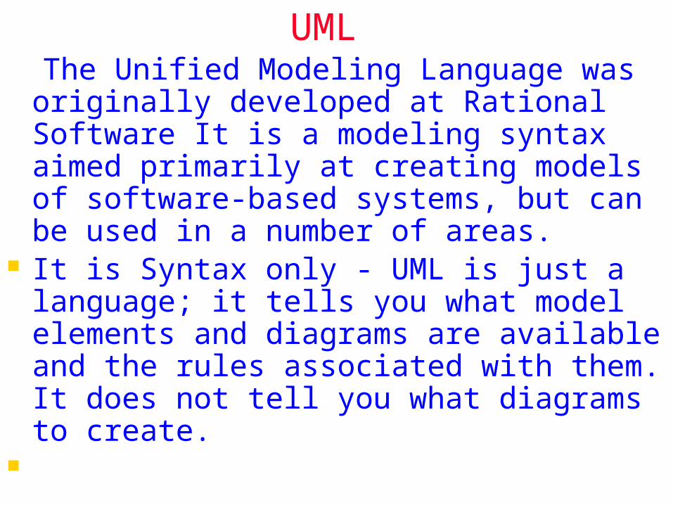
UML The Unified Modeling Language was
originally developed at Rational Software It is a modeling syntax aimed primarily at creating models of software-based systems, but can be used in a number of areas.
It is Syntax only - UML is just a language; it tells you what model elements and diagrams are available and the rules associated with them. It does not tell you what diagrams to create.


Use Case Diagrams - shows an outside-in view of the procedures available in the use of the system. These are summary diagrams and between them should contain all use cases available in the system and so all the available functionality of the system, represented at a high level.
Static Structure Diagrams - includes object and class diagrams. Most methods use class diagrams to describe the properties of the objects in the system and their relationships. Object diagrams are rarely used, except for examples of the way in which objects interact, and these are normally shown on sequence or communication diagrams.
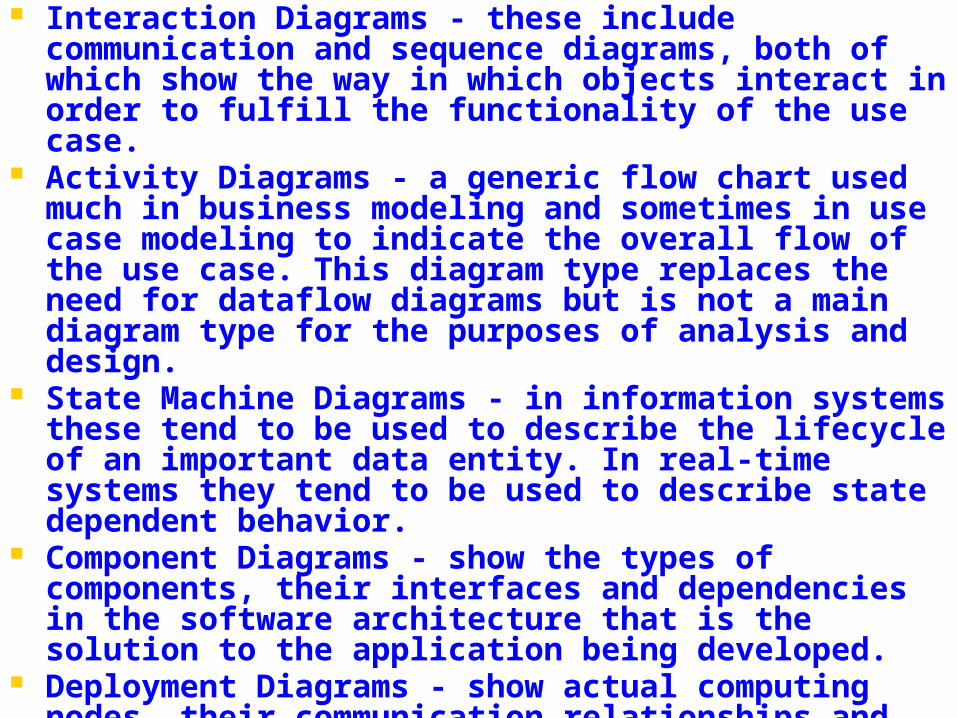
Interaction Diagrams - these include communication and sequence diagrams, both of which show the way in which objects interact in order to fulfill the functionality of the use case.
Activity Diagrams - a generic flow chart used much in business modeling and sometimes in use case modeling to indicate the overall flow of the use case. This diagram type replaces the need for dataflow diagrams but is not a main diagram type for the purposes of analysis and design.
State Machine Diagrams - in information systems these tend to be used to describe the lifecycle of an important data entity. In real-time systems they tend to be used to describe state dependent behavior.
Component Diagrams - show the types of components, their interfaces and dependencies in the software architecture that is the solution to the application being developed.
Deployment Diagrams - show actual computing nodes, their communication relationships and the processes or components that run on them.
30
Use Case Diagrams
31
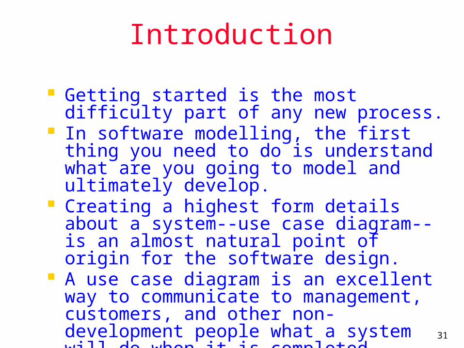
Introduction
Getting started is the most difficulty part of any new process.
In software modelling, the first thing you need to do is understand what are you going to model and ultimately develop.
Creating a highest form details about a system--use case diagram--is an almost natural point of origin for the software design.
A use case diagram is an excellent way to communicate to management, customers, and other non-development people what a system will do when it is completed.

32
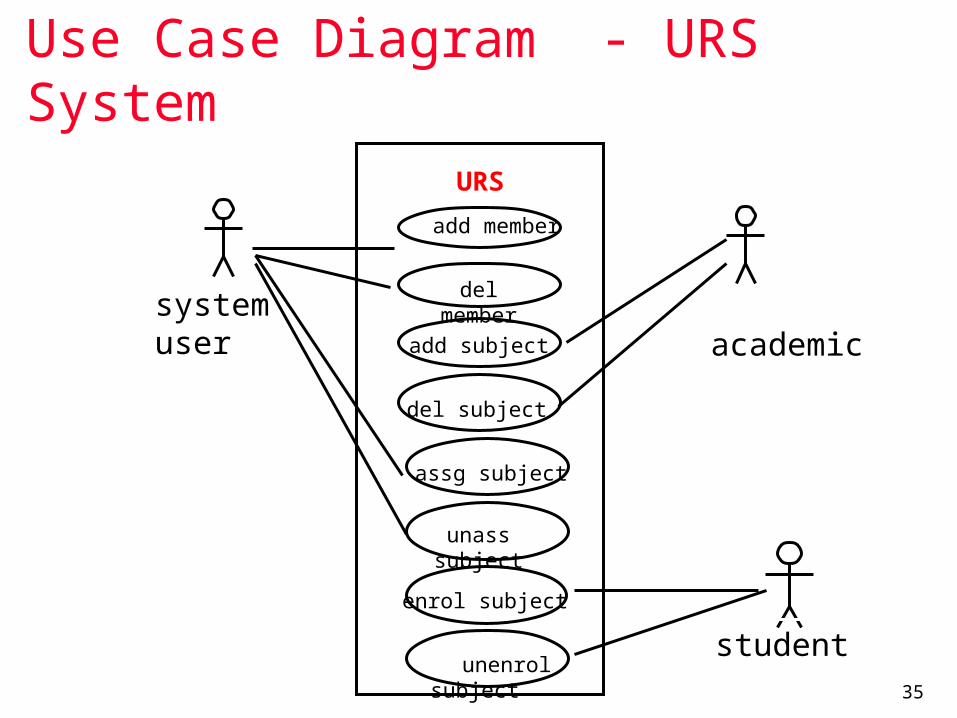
University Record System (URS)
A University record system should keep information about its students and academic staff.
Records for all university members are to include their id number, surname, given name, email, address, date of birth, and telephone number.
Students and academic staff each have their own unique ID number: studN (students), acadN (academic employee), where N is an integer (N>0).
In addition to the attributes mentioned above: Students will also have a list of subjects they are
enrolled in. A student cannot be enrolled in any more than 10 subjects.
Academic employees will have a salary, and a list of subjects they teach. An academic can teach no more than 3 subjects.

33
Some Actions Supported by URS
The system should be able to handle the following commands.
Add and remove university members (students, and academic staff)
Add and Delete subjects Assign and Un-assign subjects to
students Assign and Un-assign subjects to
academic staff.

34
Use Case Diagrams
Use Case diagrams show the various activities the users can perform on the system. System is something that performs a
function. They model the dynamic aspects of
the system. Provides a user’s perspective of the
system.
35
Use Case Diagram - URS System
systemuser academic
student
URS
del member
add member
add subject
del subject
assg subject
unass subject
enrol subject
unenrol subject
36
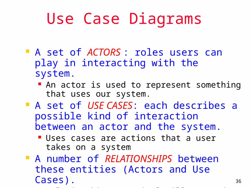
Use Case Diagrams
A set of ACTORS : roles users can play in interacting with the system. An actor is used to represent something that
uses our system. A set of USE CASES: each describes a
possible kind of interaction between an actor and the system. Uses cases are actions that a user takes on a
system A number of RELATIONSHIPS between
these entities (Actors and Use Cases). Relationships are simply illustrated with a line
connecting actors to use cases.
37
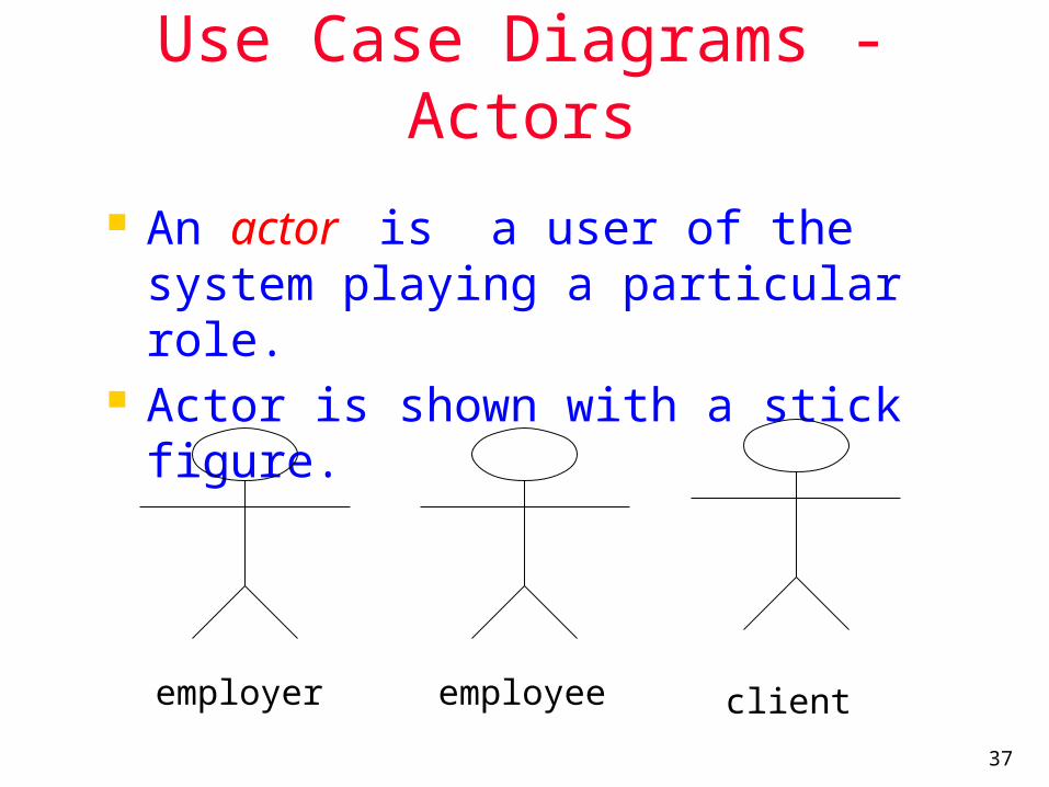
Use Case Diagrams - Actors
An actor is a user of the system playing a particular role.
Actor is shown with a stick figure.
employee clientemployer

38
Use Case Diagrams – Use Cases
Use case is a particular activity a user can do on the system.
Is represented by an ellipse. Following are two use cases for a
library system.
ReserveBorrow
39
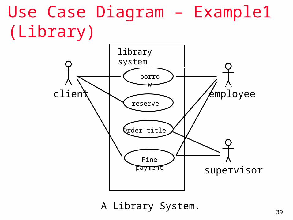
Use Case Diagram – Example1 (Library)
A Library System.
client employee
supervisor
library system
borrow
reserve
Order title
Fine payment
40
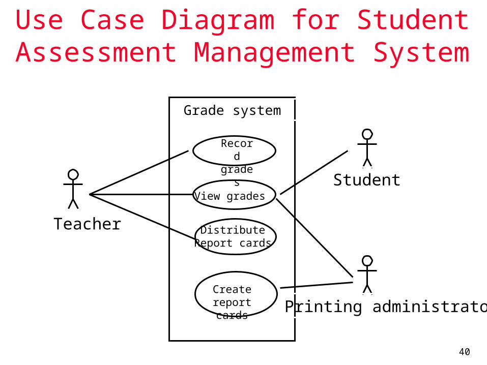
Use Case Diagram for Student Assessment Management System
Teacher
Student
Printing administrator
Grade system
Record
grades
View grades
DistributeReport cards
Create report cards
41
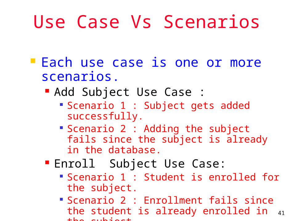
Use Case Vs Scenarios
Each use case is one or more scenarios. Add Subject Use Case :
Scenario 1 : Subject gets added successfully.
Scenario 2 : Adding the subject fails since the subject is already in the database.
Enroll Subject Use Case: Scenario 1 : Student is enrolled for the
subject. Scenario 2 : Enrollment fails since the
student is already enrolled in the subject.
Each scenario has a sequence of steps.

42
Scenarios
Each scenario has a sequence of steps. Scenario 1 : Student is enrolled for the
subject. Student chooses the “enroll subject” action. Check the student has enrolled in less than
10 subjects. Check if the subject is valid. Assign the subject to the student.
43
Scenarios
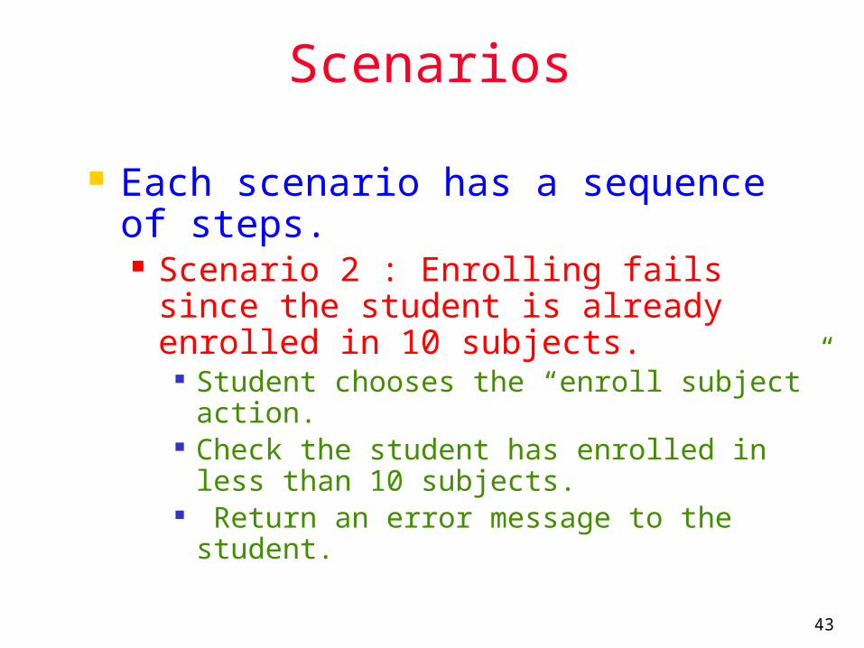
Each scenario has a sequence of steps. Scenario 2 : Enrolling fails since the
student is already enrolled in 10 subjects.
Student chooses the “enroll subject” action. Check the student has enrolled in less than
10 subjects. Return an error message to the student.

44
Use Case Diagrams - Relationships
Inclusion Inclusion enables to reuse one use case's
steps inside another use case. Extension
Allows creating a new use case by adding steps to existing use cases
Generalization Allows child use cases to inherit behavior from
parent use cases
45
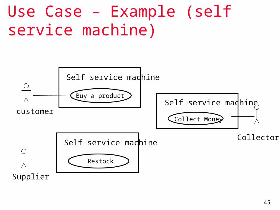
Use Case – Example (self service machine)
Restock
Supplier
Self service machine
Buy a product
customer
Self service machine
Collect Money
Self service machine
Collector
46
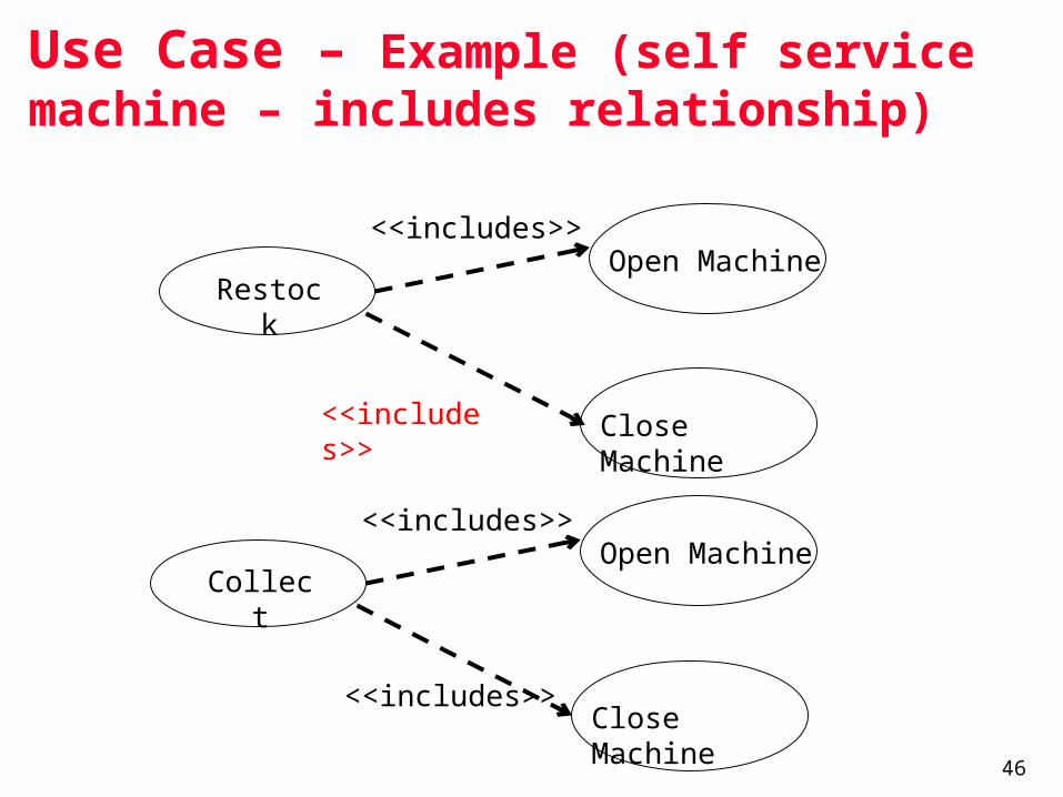
Use Case – Example (self service machine – includes relationship)
Close Machine
Restoc
k
Close Machine
Open Machine
<<includes>>
<<includes>>
Collect
Open Machine
<<includes>>
<<includes>>

47
Use Case – Example (self service machine – extends relationship)
Restoc
k
Close Machine
Open Machine
<<includes>>
<<includes>>
Restock According to Sales
<<extends>>

48
Use Case – Example (self service machine – generalize relationship): Actor-to-Actor relationship
Supplier Agent
Restocker Collector
generalized actor
specialized actor
49
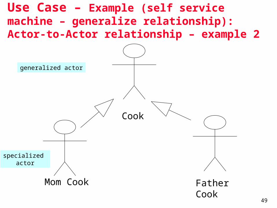
Use Case – Example (self service machine – generalize relationship): Actor-to-Actor relationship – example 2
Cook
Mom Cook Father Cook
generalized actor
specialized actor

50
Use Case – Example (self service machine)
Close Machine
Restock
Close Machine
Open Machine
<<includes>>
<<includes>>
Collect
Open Machine
<<includes>>
<<includes>>
Buy a product
Restock according to sales
customer
supplier
Self Service Machine

51
From Use Case to Classes
52
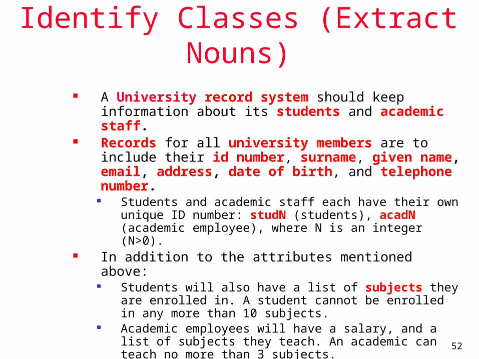
Identify Classes (Extract Nouns)
A University record system should keep information about its students and academic staff.
Records for all university members are to include their id number, surname, given name, email, address, date of birth, and telephone number.
Students and academic staff each have their own unique ID number: studN (students), acadN (academic employee), where N is an integer (N>0).
In addition to the attributes mentioned above: Students will also have a list of subjects they are
enrolled in. A student cannot be enrolled in any more than 10 subjects.
Academic employees will have a salary, and a list of subjects they teach. An academic can teach no more than 3 subjects.
53
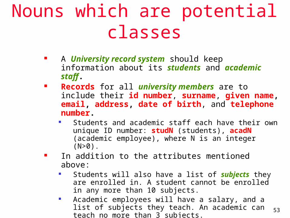
Nouns which are potential classes
A University record system should keep information about its students and academic staff.
Records for all university members are to include their id number, surname, given name, email, address, date of birth, and telephone number.
Students and academic staff each have their own unique ID number: studN (students), acadN (academic employee), where N is an integer (N>0).
In addition to the attributes mentioned above: Students will also have a list of subjects they are
enrolled in. A student cannot be enrolled in any more than 10 subjects.
Academic employees will have a salary, and a list of subjects they teach. An academic can teach no more than 3 subjects.
54
Classes identified in the first pass
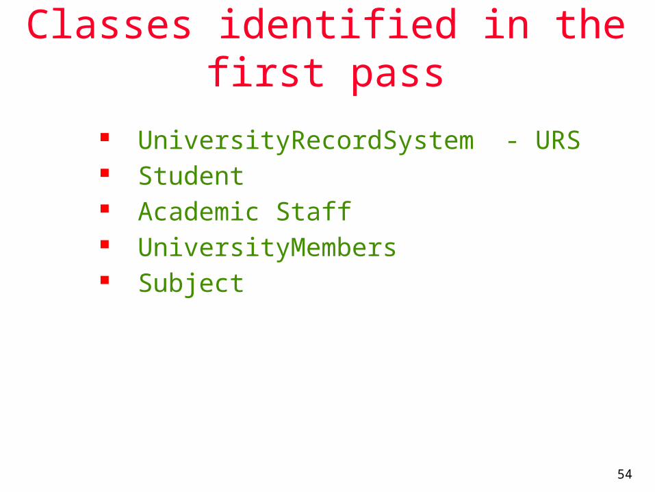
UniversityRecordSystem - URS Student Academic Staff UniversityMembers Subject

55
URS - High Level Class Diagram
URSDataBase
UniversityMember
AcademicStaff Student
Subject
1
*has
1
*
has
teaches
0..3
1
takes *
0…10

56

57
58

59

60
61
62
63

64

65
66
67
68

69
70
71
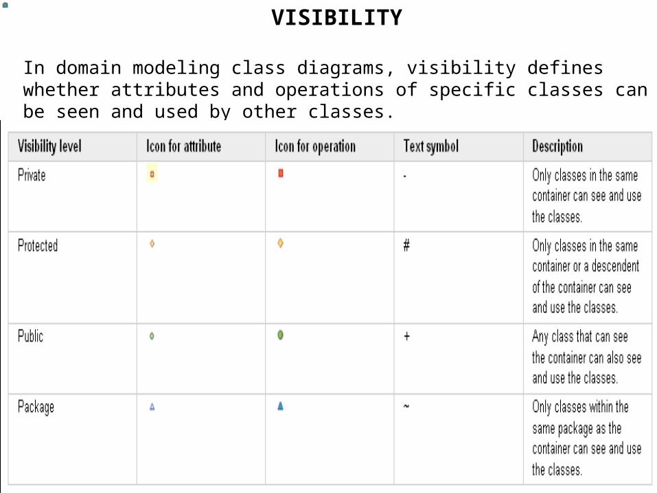
VISIBILITY
In domain modeling class diagrams, visibility defines whether attributes and operations of specific classes can be seen and used by other classes.

72