
Object Oriented Modeling of Rotating Electrical Machinescdn.intechweb.org/pdfs/14401.pdfIn this book...
27
1. Introduction The simulation of electric machines is required in many fields of applications. For the simulation of electric vehicles or hybrid electric vehicles it is often important to take multi physical effects into account. Only the full coupling of different physical domains allows a systemic analysis of the entire power train. The electric energy storage, power electronics, control and electric machines may have some kind of forced air or liquid cooling. The cooling circuits of each of the electric devices may be coupled or not. Depending on the complexity of the vehicle, the mutual coupling of thermal, mechanical and electrical effects may be crucial when the entire electric power train shall be designed. A flexible and open environment for modeling the electric energy storage, the power electronics, the electric machines, gears and clutches is thus very beneficial in the design phase. In this book chapter object oriented models of rotating electric three phase machines will be presented. To these machines will be referred with the general term induction machines. Particular machines handled in this paper are • asynchronous induction machines with squirrel cage, • asynchronous induction machines with slip rings, • synchronous reluctance machines, • electrical excited synchronous machines and • permanent magnet synchronous machines. For modeling the machines the language Modelica is used. The presented models are summarized in a library, which is available open source. This library takes the following loss mechanisms into account: temperature dependent copper (ohmic) losses, core losses, friction losses, stray load losses and brush losses which is certainly suitable for most applications. However, the motivation for developing the presented electric machines library is also the expandability of the library, being very powerful for a wide range of advanced drive applications. The expandability of the library enables an extension by considering additional effects, e.g., saturation, deep bar effects, thermal behavior, etc. 2. Modelica The Modelica Association is a non-profit and non-government association which is developing and maintaining the Modelica language, see Fritzson (2004). Modelica is an object Object Oriented Modeling of Rotating Electrical Machines Christian Kral and Anton Haumer AIT Austrian Institute of Technology GmbH Austria 8 www.intechopen.com
Transcript of Object Oriented Modeling of Rotating Electrical Machinescdn.intechweb.org/pdfs/14401.pdfIn this book...

1. Introduction
The simulation of electric machines is required in many fields of applications. For thesimulation of electric vehicles or hybrid electric vehicles it is often important to take multiphysical effects into account. Only the full coupling of different physical domains allows asystemic analysis of the entire power train. The electric energy storage, power electronics,control and electric machines may have some kind of forced air or liquid cooling. The coolingcircuits of each of the electric devices may be coupled or not. Depending on the complexity ofthe vehicle, the mutual coupling of thermal, mechanical and electrical effects may be crucialwhen the entire electric power train shall be designed. A flexible and open environment formodeling the electric energy storage, the power electronics, the electric machines, gears andclutches is thus very beneficial in the design phase.In this book chapter object oriented models of rotating electric three phase machines willbe presented. To these machines will be referred with the general term induction machines.Particular machines handled in this paper are
• asynchronous induction machines with squirrel cage,
• asynchronous induction machines with slip rings,
• synchronous reluctance machines,
• electrical excited synchronous machines and
• permanent magnet synchronous machines.
For modeling the machines the language Modelica is used. The presented models aresummarized in a library, which is available open source. This library takes the following lossmechanisms into account: temperature dependent copper (ohmic) losses, core losses, frictionlosses, stray load losses and brush losses which is certainly suitable for most applications.However, the motivation for developing the presented electric machines library is alsothe expandability of the library, being very powerful for a wide range of advanced driveapplications. The expandability of the library enables an extension by considering additionaleffects, e.g., saturation, deep bar effects, thermal behavior, etc.
2. Modelica
The Modelica Association is a non-profit and non-government association which isdeveloping and maintaining the Modelica language, see Fritzson (2004). Modelica is an object
Object Oriented Modeling of Rotating Electrical Machines
Christian Kral and Anton Haumer
AIT Austrian Institute of Technology GmbH Austria
8
www.intechopen.com

oriented equation based language for modeling multi physical systems, e.g., analog electrical,digital, mechanical, thermal, magnetic, hydraulic, pneumatic, control, etc.A Modelica library is a very convenient and reliable way to summarize and maintaindeveloped and tested Modelica models (classes). The most prominent model library is theModelica Standard Library, which contains a huge set of models (classes) out of manyscientific fields. This library is also maintained by the Modelica Association. The entireModelica Standard Library is open source and can be freely used, distributed and modified.The authors of the proposed book chapter are members of the Modelica Association andcontributed to the control, thermal, mechanical, electrical multiphase, and electric machinespackages of the Modelica Standard Library.Modelica allows the modeling of multi physical systems in an object oriented way. Mostmodels (classes) define interfaces and the model equations only refer to the interfaces andinternal variables. The interfaces may either be signal connectors as they are used in control,or physical connectors as they are used for physical models. These connectors consist of pairsof potential and flow variables, e.g., the electric potential and the electric current in case of anelectric connector. A more complex model can be accomplished by connecting the connectorsof different objects to a a more complex object. The potential variables of connected interfacesare set equal as implied by Kirchhoff’s voltage law. According to Kirchhoff’s current law thesum of flow variables of the connected connectors is set to zero.The relations between connector variables—describing the behavior of the component—areformulated in an acausal way, i.e., independent of the later usage of the component. Insteadof using assignments,
v:=R*i; // assign resistance multiplied by current to voltage drop
as in most programming languages, equations are used:
v/R=i; // voltage drop divided by resistance equals current
A software tool gathers all (ordinary) differential and algebraic equations, simplifies theset of equations (e.g. solving some of the algebraic equations analytically), and numericallyintegrates and solves the simplified set of equations. Thus the formulation of e.g. Ohm’s law(for a resistor model) is independent on whether current flowing through the component orvoltage applied to its terminals is prescribed by the system.The advantage of the object oriented approach is that redundant model code can be avoided.This increases the maintainability and reduces the fault liability of the code. In Modelicathe generalization of the term model is a class, which may be, e.g., a model, a function ora package—which is a container for additional classes, like, e.g., a directory in a file structure.A tested class can be re-used in other models through inheritances. Modelica supports twodifferent kinds of inheritance. First, the extension of code, i.e., the inserting (extending) ofcode or code fragments in classes. The second kind of inheritance is instantiation which createsinstances of classes which can be accessed through their instance names. For example, whenmodeling an electrical network of concentrated elements, different instances of, e.g., resistorsand inductors may be used.
model NetworkModelica.Electrical.Analog.Basic.Resistor R1(R=1);Modelica.Electrical.Analog.Basic.Resistor R2(R=10);Modelica.Electrical.Analog.Basic.Inductor L1(L=0.01);...
end Network;
136 Advances in Computer Science and Engineering
www.intechopen.com

The class names starting with Modelica.Electrical.Analog.Basic. refer to standardcomponents of the Modelica Standard Library. The dots in the name nomenclature separatedifferent hierarchical levels. The class definitions of the resistor and inductor inherit codethrough extension from the partial model OnePort, which contains the interface connectorsand basic variable definitions.
partial model OnePortModelica.SIunits.Voltage v;Modelica.SIunits.Current i;Modelica.Electrical.Analog.Interfaces.PositivePin p;Modelica.Electrical.Analog.Interfaces.NegativePin n;
equation
v = p.v - n.v;0 = p.i + n.i;i = p.i;
end OnePort;
The keyword partial in this model indicates that the number of variables and equations isnot balanced. Different models and partial models may be recursively access code throughextension. A non-partial model extending from one or more partial models needs to provideadditional equations (and variables) such that the numbers of variables and equations arebalanced.In Modelica physical dimensions of parameters and variables can be assigned. In the Modelicapackage Modelica.SIunits all the base SI units and many derived SI units are provided.When translating a model for the simulation of a particular problem, a unit check of all of theinvolved equations is performed. This way it can be ensured, that consistency problems ofphysical equations can be avoided.
3. Electric machine components
An electric machine is an electro mechanical energy converter. The object interfaces are the(electrical) terminal connections of the windings, the (rotational) shaft end and housing, aswell as a thermal connector incorporating the significant thermal regions and loss sourcesof the machine. With reference to asynchronous and synchronous induction machines twodifferent implementations of electric machine models are included in the Modelica StandardLibrary. The first implementation relies on space phasor theory and this is the library that ispresented in this book chapter. The second implementation is based on magnetic fundamentalwave models—with respect to the spatial electro magnetic field. The space phasor basedmachines library was originally released in 2004 and was heavily improved over the lastyears. The other machines library is included in the Modelica Standard Library since version3.2, which has been released in 2010. Both machine implementations are fully compatible andmodel the transient behavior of induction machines in the time domain. For DC machines andtransformers a time transient (and an electrically stationary) implementation is also includedin the Modelica Standard Library, which will, however, not be addressed in this book chapter.The basic idea of the object oriented modeling in electric machines is that each effect whichcan be separated from others is encapsulated in an object. Typical machine specific objects arewinding resistances, winding stray inductances, cage models and the air gap model, whichtakes the electro mechanical power conversion and the magnetic main field into account.Other objects are the inertia, and loss models related to mechanical friction, eddy currentsin the core, stray load effects and brush contact. Each loss model takes a consistent power
137Object Oriented Modeling of Rotating Electrical Machines
www.intechopen.com

balance into account, such that all dissipated losses are always considered in a respectivethermal connector. The loss models have been presented and validated against measurementsin Haumer et al. (2009). For the mechanical components actio et reactio applies. For each torqueacting on the stator and rotor side of, e.g., the air gap and friction model, the torques have thesame numeric values, but different signs. Different machines, such as asynchronous inductionmachines with squirrel cage and slip ring rotor, and synchronous machines with permanentmagnets, electrical excitation, etc., are modeled out of a minimal subset of components. Thisway the object oriented Modelica models of electric machines become code and run-timeefficient and certainly very robust.
3.1 Assumptions
The induction machine models are summarized in the packageModelica.Electrical.Machines of the Modelica Standard Library. For these machinemodels the following assumptions apply:
• the number of phases is restricted to three
• the phase windings are fully symmetrical
• the inductances are constant and thus the relationships between flux linkages and currentsare linear
• saliency effects, represented by different inductances of the d- and q-axis are considered forthe synchronous machines models
• cross coupling of inductances is not modeled
• deep bar effects are not taken into account
• only (spatial) fundamental wave effects of the magnetic field are taken into account
• time transients of electrical, mechanical and thermal quantities are not restricted
3.2 Electrical concept
The interface definition of the electric pin in Modelica.Electrical.Analog.Interfaces.Pin
consists of the electric potential and the current being a flow quantity.
connector PinModelica.SIunits.Voltage v;flow Modelica.SIunits.Current i;
end Pin;
In order to model multi phase machines an electric plug is defined inModelica.Electrical.MulitiPhase.Interfaces.Plug. This plug contains m=3 pinsby default:
connector Plugparameter Integer m=3;Modelica.Electrical.Analog.Interfaces.Pin pin[m];
end Plug;
In all instances of the plug, m is finally set to three when applied in the machines package,since only three phase machines are modeled.
138 Advances in Computer Science and Engineering
www.intechopen.com

3.3 Mechanical concept
For the rotating electric machine models only rotating one dimensionaleffects need to be taken into account. The rotational interfaces definitions ofModelica.Mechanics.Rotational.Interfaces.Flange_a are:
connector Flange_aModelica.SIunits.Angle phi;flow Modelica.SIunits.Torque tau;
end Flange_a
In the rotational package the rotational angle phi servers as potential quantity and torque tauis the flow quantity.
3.4 Thermal concept
Each loss component is equipped with a heat port which carries the heat flow as flow variableand the accessory operating temperature as potential quantity. The connector definition ofModelica.Thermal.HeatTransfer.Interfaces.HeatPort is:
connector HeatPortModelica.SIunits.Temperature T;flow Modelica.SIunits.HeatFlowRate Q_flow;
end HeatPort;
Each machine model has a conditional super heat port, which consists of as many heat portsas loss effects are considered. If the super heat port of a machine is enabled, the heat portsof the loss components are connected with this super heat port. This way the machine modelcan be coupled with an external thermal model. If the heat port of a machine is disabled theloss components are thermally connected to internal temperature sources representing fixed(operating) temperatures. In this case, the losses are entirely dissipated in internal temperaturesources. The concept of coupling an external thermal model with the electro-mechanicalmodel is presented in detail in Haumer et al. (2010).
3.5 Resistance
The resistor objects applied in the machine models are directly taken from the Modelicapackage Modelica.Electrical.Analog.Basic.Resistor, see resistor in tab. 1. This modelconsists of two electrical pins and one thermal connector. This resistance is modeledtemperature dependent
R = RRef*(1+alphaRef*(T-TRef));
where RRef is the reference resistance at the reference temperature TRef and alphaRef is thelinear temperature coefficient at TRef. The actual resistance R is dependent on the operatingtemperature T which is obtained from the thermal connector of this model.Three phase resistors are directly taken from the Modelica packageModelica.Electrical.MultiPhase.Basic.Resistor, see resistor in tab. 1. This modelconsists of two electrical three phase plugs, one thermal connector and three single phaseresistors. Since the machine models are assumed to have symmetrical phase windings theindividual reference resistances for each phase are set to equal values in the machine models.
139Object Oriented Modeling of Rotating Electrical Machines
www.intechopen.com

Icon Class name Comment
ResistorTemperature dependent single phase resistor with heatport
ResistorTemperature dependent three phase resistor with heatport
StrayLoadStray load losses with heat port and rotor and statorrotational flange
Friction Friction losses
Brushes Carbon brush losses
SpacePhasorTransforms multi phase quantities to space phasors andzero sequence components
Inductor Linear single phase inductor
Inductor Linear space phasor inductor
Core Core losses (without hysteresis losses)
SquirrelCage Symmetrical squirrel cage with heat port
DamperCage Salient damper cage with heat port
ElectricalExcitationTransforms excitation voltage and current to spacephasors
PermanentMagnetTransforms permanent magnet excitation to anequivalent space phasor
Inertia Rotating mass
Table 1. Components of the electric machines library
140 Advances in Computer Science and Engineering
www.intechopen.com

3.6 Stray load losses
The stray load loss model applied to all the induction machine models is originally inspiredby the standard 60034-2 (1998) and extended by a thesis of Lang (1984). The stray load lossesare modeled to be proportional to the square of the root mean square (RMS) current and to aparticular power of speed. In order to consistently cover the loss balance in the machine, strayload losses are considered as an equivalent torque, acting on the rotor (and stator housing,respectively).
tau = tauRef*(I/IRef)^2*(w/wRef)^power_w;
The term wRef*tauRef represents the reference stray load losses at rated current IRef andrated angular speed wRef. The parameter power_w is a positive real quantity in this model.The stray load loss model consists of two plugs and two mechanical flanges. One mechanicalflange is supposed to be connected with the rotor and the other one shall be connected withthe stator (housing). The torques of the two mechanical flanges have the same numeric valuesbut different signs. The electrical connectors are part of the stator (winding) circuit. The RMSvalue of the current is actually computed from the instantaneous values of the phase currents.The actual losses dissipated by this model are equal to the heat flow of thermal connector:
heatPort.Q_flow = tau*w;
The heat flow and losses, respectively, are independent of the temperature of the heat port. Yetfor operating this model an (arbitrary) operating temperature has to be provided at the heatport (see tab. 1).
3.7 Friction losses
The friction losses are modeled by:
tau = tauRef*(w/wRef)^power_w;
In this equation wRef*tauRef represent the reference friction losses at reference angularvelocity wRef. The exponent power_w is a positive real quantity.In order to avoid numerical problems the torque speed relationship is approximated as a linearcurve around the zero crossing. The linear speed region is, however, much smaller than thereference reference speed.
tau = if w >= +wLinear then
+tauRef*(+w/wRef)^power_welse if w <= -wLinear then
-tauRef*(-w/wRef)^power_welse
tauLinear*(w/wLinear);
This model requires two mechanical flanges to be connected with the rotor and stator(housing), respectively. The thermal connector dissipates the losses
heatPort.Q_flow = tau*w;
independent of the actual operating temperature, which has to be provided externally due toconsistency reasons, see tab. 1.
141Object Oriented Modeling of Rotating Electrical Machines
www.intechopen.com
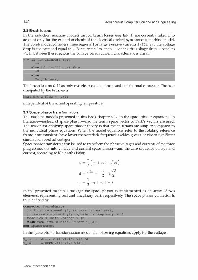
3.8 Brush losses
In the induction machine models carbon brush losses (see tab. 1) are currently taken intoaccount only for the excitation circuit of the electrical excited synchronous machine model.The brush model considers three regions. For large positive currents i>ILinear the voltagedrop is constant and equal to V. For currents less than -ILinear the voltage drop is equal to-V. In between these regions the voltage versus current characteristic is linear.
v = if (i>+ILinear) then
+Velse if (i<-ILinear) then
-Velse
V*i/ILinear;
The brush loss model has only two electrical connectors and one thermal connector. The heatdissipated by the brushes is:
heatPort.Q_flow = -v*i;
independent of the actual operating temperature.
3.9 Space phasor transformation
The machine models presented in this book chapter rely on the space phasor equations. Inliterature—instead of space phasor—also the terms space vector or Park’s vectors are used.The reason for applying space phasor theory is that the equations are simpler compared tothe individual phase equations. When the model equations refer to the rotating referenceframe, time transients have lower characteristic frequencies which gives also rise to significantsimulation speed advantages.Space phasor transformation is used to transform the phase voltages and currents of the threeplug connectors into voltage and current space phasor—and the zero sequence voltage andcurrent, according to Kleinrath (1980):
v =2
3
(
v1 + av2 + a2v3
)
a = ej23 π = − 1
2+ j
√3
2
v0 =1
3(v1 + v2 + v3)
In the presented machines package the space phasor is implemented as an array of twoelements, representing real and imaginary part, respectively. The space phasor connector isthus defined by:
connector SpacePhasor// First component [1] represents real part,
// second component [2] represents imaginary part
Modelica.SIunits.Voltage v_[2];flow Modelica.SIunits.Current i_[2];
end SpacePhasor;
In the space phasor transformation model the following equations apply for the voltages:
v_[1] = (2/3)*(v[1]-v[2]/2-v[3]/2);v_[2] = (1/sqrt(3))*(v[2]-v[3]);
142 Advances in Computer Science and Engineering
www.intechopen.com

The zero sequence connector zero is modeled as a regular electrical pin. The respective zerosequence voltage is determined by the following acausal relationship:
3*zero.v = v[1]+v[2]+v[3];
The same relationships also apply for the space phasor currents and the zero sequence current.In each of the presented machines the zero sequence inductance of the respective (statoror rotor) winding is then connected to the zero sequence connector of the space phasortransformation model, see section 4 and tab. 1.
3.10 Zero inductance
In the presented machines package the zero inductances are modeled by meansof single phase inductors which are taken directly from the Modelica packageModelica.Electrical.Analog.Basic.Inductor (see inductor model in tab. 1). The sameinductor model is used for the stray inductance of single phase excitation windings.
3.11 Stray inductance
In the presented machines package stray inductances are modeled by means of inductors withspace phasor connectors and components (see inductor model in tab. 1).
v_[1] = L[1]*der(i_[1]);v_[2] = L[2]*der(i_[2]);
The operator der() represents the time derivative and the inductances L[1] and L[2] are theinductances in the two axes of the actual space phasor reference frame.
3.12 Core losses
In the current implementation of the core loss model only eddy current losses are takeninto account (tab. 1). Therefore, the actual core conductance Gc is assumed to be constant,calculated from reference core losses at given reference voltage. The electrical interfaces ofthe model are space phasor connectors. The space phasor relationship between voltages andcurrents is simply
i_ = Gc*v_;
and dissipated losses are:
heatPort.Q_flow = -3/2*(+v_[1]*i_[1]+v_[2]*i_[2]);
Hysteresis losses are not considered in the actual implementation, since hysteresis losses areusually modeled in the frequency domain as presented by Lin et al. (2003), but the presentedmodel is strictly a time domain approach.
3.13 Air gap, magnetizing inductance and torque
The air gap model takes the magnetizing inductance and the electro mechanical powerconversion into account. The stator and rotor side of the model have space phasor connectorsrepresenting the voltage and current phasors with respect to the stator and rotor fixedreference frame. Additionally the air gap model has one rotor and one stator (housing) relatedrotational flange.In the proposed machine models the entire magnetic circuits are represented by equivalentair gap inductances. In order to express the relationship between stator and rotor currentsand magnetizing inductance, the stator and rotor space phasors have to refer to one commonreference frame. It is thus required to either
143Object Oriented Modeling of Rotating Electrical Machines
www.intechopen.com

1. transform the stator space phasors to the rotor fixed reference frame or
2. transform the rotor space phasors to the stator fixed reference frame.
For both cases an air gap model is available in the presented machines library. In the followingonly the first implementation will be discussed, as this represents the more general approach.In the following the rotor fixed rotor current space phasor is referred to as i_rr. The firstletter after the underscore represents the rotor side and the second letter indicates the referenceframe—in this case the rotor fixed reference frame. The stator fixed stator current space phasori_ss is transformed to the rotor fixed reference frame by means of a rotation by the negativeangle gamma. This quantity is the difference of angular position of the stator and rotor rotationflange, multiplied by the number of pole pairs. The rotor fixed stator current space phasori_sr and the rotor current space phasor i_rr add up the magnetizing current phasor:
i_mr = i_sr+i_rr;
The main flux linkage phasor psi_mr of the air gap is thus determined by
psi_mr[1] = Lmd*i_mr[1];psi_mr[2] = Lmq*i_mr[2];
where Lmd and Lmq are the magnetizing inductances in the direct (d) and quadrature (q) axisof the rotor. The different inductances in both axis allow the consideration of saliency effectsof the magnetic reluctance of the rotor.The inner (electrical) torque of the air gap model is determined by the vector product of themagnetizing flux and the stator current space phasor:
tauElectrical = 3/2*p*(i_sr[2]*psi_mr[1] - i_sr[1]*psi_mr[2]);
In this equation p represents the number of pole pairs. As for all mechanically interactingmodels, the torque at rotor shaft and the stator (housing) have the same numeric quantitiesbut different signs to correctly consider actio et reactio; see tab. 1.
3.14 Squirrel and damper cage
For asynchronous induction machines symmetrical squirrel cages are used, whereassynchronous machines use damper cages with different equivalent resistances and strayinductances in direct (d) and quadrature (q) axis. In this sense, the symmetrical squirrel cageis a restricted damper cage with equal parameters in the two axis; see tab. 1. The relationshipbetween the two axis components of the voltages and current spaces phasors are:
v_[1] = Rrd * i_[1] + Lrsigmad * der(i_[1]);v_[2] = Rrq * i_[2] + Lrsigmaq * der(i_[2]);
The resistances Rrd and Rrq are again temperature dependent, and the model is equippedwith a heat port. The constant inductances Lrsigmad and Lrsigmaq are the stray inductancesof the cages in the direct (d) and quadrature (q) axis.
3.15 Electrical excitation
For electrically excited synchronous machines, excitation voltage and current have to betransformed to equivalent space phasors (direct axis components), taking the conversionfactor between rotor and stator into account:
ve = v_[1]*turnsRatio*3/2;i_[1] = -ie*turnsRatio;i_[2] = 0;
144 Advances in Computer Science and Engineering
www.intechopen.com

With given main field inductance in d-axis Lmd, the turnsRatio can be calculated from no-loadvoltage at given speed (frequency) and excitation current IeOpenCircuit:
sqrt(2)*VsNominal = 2*pi*fsNominal*Lmd*IeOpenCircuit*turnsRatio
3.16 Permanent magnet
For permanent magnet synchronous machines, the effect of the permanent magnet canbe considered like a constant DC excitation current (providing a constant remanent flux,neglecting the detailed B-H-characteristic of the magnet material):
i_[1] = -Ie;i_[2] = 0;
3.17 Inertia
Inertia models are required to model the rotor and stator (housing) inertia effects with respectto one rotational axis. The relationship between torque tau and angular position phi of theflange is:
phi = flange_a.phi;phi = flange_b.phi;w = der(phi);a = der(w);J*a = flange_a.tau + flange_b.tau;
The inertia model has two flanges, flange_a and flange_b which are rigidly connected.From a modeling point of view the two different connectors are not required, but are usedfor convenience reasons when graphically connecting components, see tab. 1.
4. Induction machine models
4.1 Partial induction machine model
The partial induction machine model (see Fig. 1) comprises all components that are commonto all induction machines models:
• electrical three phase plugs plug_sp and plug_sn representing the beginning and end ofthe stator three phase windings; star or delta connection has to be provided outside of themachine model
• stray load losses strayLoad: see sec. 3.6
• resistances rs of the three phase stator windings: see sec. 3.5
• space phasor transformation spacePhasorS of stator voltages and currents: see sec. 3.9
• stator zero sequence inductor lszero: see sec. 3.10; the inductance is set equal to the strayinductance by default, but can be parametrized differently
• stray inductance lssigma of the three phase stator windings: see sec. 3.11
• stator core losses statorCore: see sec. 3.12
• friction losses friction: see sec. 3.7
• rotor moment of inertia inertiaRotor (see sec. 3.17) and a rotational flange, representingthe shaft end
145Object Oriented Modeling of Rotating Electrical Machines
www.intechopen.com

• stator moment of inertia inertiaStator (see sec. 3.17) and an optional rotational flange,representing the housing
• a replaceable internal heat port internalHeatPort, an optional replaceable thermalambient thermalAmbient and an optional replaceable thermal port thermalPort (seesec. 3.4)
For the user’s convenience, a boolean parameter useSupport determines whether the statorflange of the air gap model is connected to an internal mechanically fixed point fixed),or to the stator moment of inertia and the rotational flange support. If the user choosesuseSupport = true, the flange support has to be connected to an external mechanical circuit,e.g., representing an elastic mounting.All induction machine models extend from this partial model, i.e., they inherit allcommon components, replacing the thermal ports and thermal ambient by machine specificcomponents and add all other specific components (e.g. air gap model).
Fig. 1. Partial model of induction machines
4.2 Asynchronous induction machine with squirrel cage
The asynchronous induction machine with squirrel cage (see fig. 2) inherits from the partialinduction machine model (see sec. 4.1) and adds the following machine specific components:
• air gap model airGapS in the stator fixed reference frame: see sec. 3.13
• squirrel cage squirrelCageR in rotor fixed reference frame: see sec. 3.14
4.3 Asynchronous induction machine with slip ring rotor
The asynchronous induction machine with slip ring rotor (see fig. 3) inherits from the partialinduction machine model (see sec. 4.1) and adds the following machine specific components:
• air gap model airGapS in the stator fixed reference frame: see sec. 3.13
146 Advances in Computer Science and Engineering
www.intechopen.com

Fig. 2. Asynchronous induction machine with squirrel cage
• electrical threephase plugs plug_rp and plug_rn for beginning and end of the rotor threephase windings; star or delta connection has to be provided outside of the machine model
• resistances rr of the three phase rotor windings: see sec. 3.5
• space phasor transformation spacePhasorR of rotor voltages and currents: see sec. 3.9
• rotor zero sequence inductor lrzero: see sec. 3.10; the inductance is set equal to the rotorstray inductance by default, but can be parametrized differently
• stray inductance lrsigma of the three phase rotor windings: see sec. 3.11
• rotor core losses rotorCore: see sec. 3.12
• brush losses (see sec. 3.8) are neglected, since standards consider brush voltage dropdependent on root mean square of current; during transient operation RMS current cannotbe calculated; the dependency of brush voltage drop on instantaneous current will beinvestigated
The space phasor transformation of rotor voltages and currents has to take into accountadditionally the turns ratio between stator and rotor winding:
v′rvr
=effective number of stator turns
effective number of rotor turns
This parameter can either be determined from a pre-processing calculation of the machine, orcalculated from the measured locked-rotor voltage vr0:
v′r0vr0
=vsvr0
· |jωsLm||rs + jωsLs|
147Object Oriented Modeling of Rotating Electrical Machines
www.intechopen.com

Fig. 3. Asynchronous induction machine with slip ring rotor
4.4 Synchronous reluctance machine
The synchronous reluctance machine (see fig. 4) inherits from the partial induction machinemodel (see sec. 4.1) and adds the following machine specific components:
• air gap model airGapR in the rotor fixed reference frame (see sec. 3.13), since saliency ofthe rotor has to be taken into account
• optional damper cage model (see sec. 3.14) which can be enabled/disabled by means ofthe boolean parameter useDamperCage; since the damper cage can be disabled (machinewithout damper cage), an auxiliary heat flow sensor has to be used for connection to thethermal port
4.5 Electrical excited synchronous machine
The electrical excited synchronous machine (see fig. 5) inherits from the partial inductionmachine model (see sec. 4.1) and adds the following machine specific components:
• air gap model airGapR in the rotor fixed reference frame (see sec. 3.13), since saliency ofthe rotor has to be taken into account
• optional damper cage model (see sec. 3.14) which can be enabled/disabled by means ofthe boolean parameter useDamperCage; since the damper cage can be disabled (machinewithout damper cage), an auxiliary heat flow sensor has to be used for connection to thethermal port
• electrical single-phase pins pin_ep and pin_en for beginning and end of the excitationwinding
• brush losses brush (see sec. 3.8) for modeling losses and the voltage drop due to brushes;if a brushless excitation system is considered, the brush loss equations can be disabled bysetting the reference voltage drop to zero
148 Advances in Computer Science and Engineering
www.intechopen.com

Fig. 4. Synchronous machine with reluctance rotor and optional damper cage
• resistance re (see sec. 3.5) of the excitation winding
• stray inductance lesigma (see sec. 3.10) of the excitation winding
• electrical excitation: see sec. 3.15
Fig. 5. Electrical excited synchronous machine with optional damper cage
149Object Oriented Modeling of Rotating Electrical Machines
www.intechopen.com
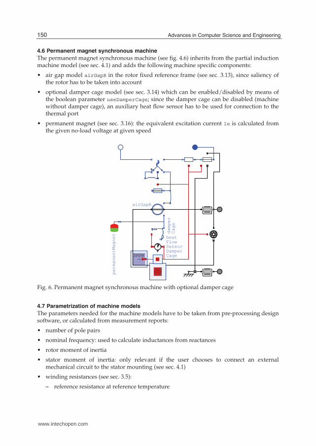
4.6 Permanent magnet synchronous machine
The permanent magnet synchronous machine (see fig. 4.6) inherits from the partial inductionmachine model (see sec. 4.1) and adds the following machine specific components:
• air gap model airGapR in the rotor fixed reference frame (see sec. 3.13), since saliency ofthe rotor has to be taken into account
• optional damper cage model (see sec. 3.14) which can be enabled/disabled by means ofthe boolean parameter useDamperCage; since the damper cage can be disabled (machinewithout damper cage), an auxiliary heat flow sensor has to be used for connection to thethermal port
• permanent magnet (see sec. 3.16): the equivalent excitation current Ie is calculated fromthe given no-load voltage at given speed
Fig. 6. Permanent magnet synchronous machine with optional damper cage
4.7 Parametrization of machine models
The parameters needed for the machine models have to be taken from pre-processing designsoftware, or calculated from measurement reports:
• number of pole pairs
• nominal frequency: used to calculate inductances from reactances
• rotor moment of inertia
• stator moment of inertia: only relevant if the user chooses to connect an externalmechanical circuit to the stator mounting (see sec. 4.1)
• winding resistances (see sec. 3.5):
– reference resistance at reference temperature
150 Advances in Computer Science and Engineering
www.intechopen.com

– reference temperature
– temperature coefficient at reference temperature
– operational temperature: only relevant if the user chooses to dissipate the losses to aninternal thermal temperature source instead of connecting an external thermal circuit(see sec. 3.4)
• stray inductance
• zero inductance of three phase windings
• magnetizing inductance (see sec. 3.13)
• stray load losses (see sec. 3.6):
– reference loss power at reference current and reference speed
– reference current
– reference speed
– exponent of stray load torque with respect to speed
• friction losses (see sec. 3.7):
– reference loss power at reference speed
– reference speed
– exponent of friction torque with respect to speed
• brush losses (see sec. 3.8):
– voltage drop
– current limit (linear changeover around current = 0)
• core losses (see sec. 3.12):
– reference loss power at reference voltage and reference frequency
– reference voltage
– reference frequency
If it is desired to neglect losses, the reference loss power (stray load losses, friction losses, corelosses) respectively the voltage drop (brush losses) can be set to zero.Resistances and inductances have to be specified per phase as they are accessible formeasurements at the respective winding terminals, except squirrel cage and damper cage.Cage parameters (see sec. 3.14) have to be specified with respect to an equivalent threephase stator winding. If temperature dependency shall be neglected, either the temperaturecoefficient can be set to zero or—in case the heat port shall not be connected to an externalthermal model (see sec. 3.4)—the operational temperature can be set equal to the referencetemperature.Additional machine specific parameters are:
• for asynchronous induction machines with slip ring rotor (see sec. 4.3), turnsRatio
between stator and rotor winding is calculated out of the parameters
– nominal stator voltage
– locked-rotor voltage
• for electrical excited synchronous machines (see sec. 4.5 and sec. 3.15), turnsRatio
between stator and excitation winding as well as excitation stray inductance require theparameters
151Object Oriented Modeling of Rotating Electrical Machines
www.intechopen.com

– nominal stator voltage
– open circuit excitation current for nominal stator voltage at nominal frequency
– stray fraction of total excitation inductance
• for permanent magnet synchronous machines (see sec. 4.6 and sec. 3.16), the calculation ofthe equivalent excitation current requires the
– open circuit stator voltage at nominal speed
5. Examples
5.1 Asynchronous induction machine with squirrel cage, started direct on line
The stator windings of an asynchronous induction machine with squirrel cage (aimc in fig. 7)is connected in delta, using the auxiliary model terminalBox which allows the selection ofeither star or delta connection. The terminalBox is series connected to an RMS current sensor(which determines the length of the current space phasor) and a switch (which is closed attime = 0.1 s). The stiff voltage supply is represented by a purely sinusoidal voltage source(sineVoltage). The machine’s shaft end is connected to the loadInertia and a quadraticspeed dependent loadTorque. The parameters of the load are selected such way that themachine load torque equals the nominal torque at nominal speed. A summary of the machineparameters is listed in tab. 2. Parameters which are not needed for parametrizing the machinemodel are listed without parameter name. In the presented example, for simplicity reasons,the temperature dependence of the resistances is neglected. All other than ohmic losses arealso not taken into account.
aimc
loadInertialoadTorque
switch
sineVoltage
D
Fig. 7. Asynchronous induction machine with squirrel cage, started direct on line
The line current shown in fig. 8 represents the length of the current space phasor divided
by√
2, which can be interpreted as equivalent RMS value for stationary operation. Thecurrent waveform reflects an electro-magnetic transient when the switch is closed. Due to
152 Advances in Computer Science and Engineering
www.intechopen.com

0.0 0.2 0.4 0.6 0.8 1.0 1.2 1.4
0
200
400
600
800
1000
1200
time[s]
rms current [A]
Fig. 8. Line current of asynchronous induction machine with squirrel cage
0.0 0.2 0.4 0.6 0.8 1.0 1.2 1.4
-400
-200
0
200
400
600
800
1000
1200
1400
1600
time[s]
speed [rpm] and el.tiorque [Nm]
torque
speed
Fig. 9. Speed and electrical torque of asynchronous induction machine with squirrel cage
153Object Oriented Modeling of Rotating Electrical Machines
www.intechopen.com

Comment Parameter name Value Unitnumber of pole pairs p 4
rotor’s moment of inertia Jr 0.29 kg · m2
nominal RMS voltage per phase 100 Vnominal RMS current per phase 100 A
nominal frequency fsNominal 50 Hz
nominal torque 161.4 Nmnominal speed 1440.45 rpm
stator resistance Rs 0.03 Ω
stator stray inductance Lssigma 0.3239 mH
stator zero sequence inductance Lszero 0.3239 mH
main field inductance Lm 9.2253 mHrotor stray inductance Lrsigma 0.3239 mH
rotor resistance Rr 0.04 Ω
Table 2. Parameters of the asynchronous induction machine with squirrel cage
the electro-magnetic transients the electrical torque developed by the machine also starts withtransient oscillations, which causes a speed ripple accordingly (fig. 9). The total moment ofinertia (machine plus load) is accelerated by the electromagnetic torque minus the quadraticspeed dependent load torque. At approximately 0.6 s the drive reaches nominal operatingconditions.
5.2 Asynchronous induction machine with slip ring rotor, started with rheostat
The stator windings of an asynchronous induction machine with slip ring rotor (aims infig. 10) is connected in delta. The stator starting switch is closed at time = 0.1 s. Themachine’s shaft end is connected to a loadInertia and a quadratic speed dependentloadTorque with the same parameters settings as in sec. 5.1. The rotor terminals areconnected to a rheostat, i.e., an external additional resistor with resistance parametersequal to four times the rotor resistance. This rheostat is shorted during the start procedureafter time = 1 s. The parameters of the simulated machine are summarized in tab. 3. Forsimplicity reasons neither temperature dependent resistances nor other loss phenomena aretaken into account.The current depicted in fig. 11, again, represents the length of the current space phasor
divided by√
2. The transient current is smaller than that of the asynchronous inductionmachine with squirrel cage due to the external rotor resistance of the rheostat. The electricaltorque developed by the machine also starts with transient oscillations, which give rise tospeed oscillations (fig. 12). The total moment of inertia of the machine including load isaccelerated by the electromagnetic torque minus the quadratic speed dependent load torque.At approximately 0.7 s the drive reaches stationary operation with the rheostat still beingswitched on. After shorting the rheostat at time = 1 s, the machine accelerates with a shorttransient to nominal speed.
5.3 Electrical excited synchronous machine, load dump
The stator windings of an electrical excited synchronous induction machine (smee in fig. 13)is connected in star, using the auxiliary model terminalBox. The machine is operatedas generator connected to a three-phase resistor and inductor by means of a switch.The electrical load has a nominal power factor of 0.8. At time = 2 s the open circuit
154 Advances in Computer Science and Engineering
www.intechopen.com

switch
sineVoltage
Arms
D
aims
rheostat
terminalbox
loadInertia
Fig. 10. Asynchronous induction machine with slip ring rotor, started with rheostat
Comment Parameter Value Unit
number of pole pairs p 4
rotor’s moment of inertia Jr 0.29 kg · m2
nominal RMS voltage per phase VsNominal 100 Vnominal RMS current per phase 100 A
nominal frequency fsNominal 50 Hz
locked rotor RMS voltage per phase VrLockedRotor 96.603 Vnominal torque 161.4 Nm
nominal speed 1440.45 rpm
stator resistance Rs 0.03 Ω
stator stray inductance Lssigma 0.3239 mH
stator zero sequence inductance Lszero 0.3239 mH
main field inductance Lm 9.2253 mHrotor stray inductance Lrsigma 0.3239 mH
rotor zero sequence inductance Lrzero 0.3239 mHrotor resistance Rr 0.04 Ω
Table 3. Parameters of the asynchronous induction machine with slip ring rotor
155Object Oriented Modeling of Rotating Electrical Machines
www.intechopen.com

0.0 0.2 0.4 0.6 0.8 1.0 1.2 1.4
0
100
200
300
400
500
600
700
time[s]
rms current [A]
Fig. 11. Line current of asynchronous induction machine with slip ring rotor and rheostat
0.0 0.2 0.4 0.6 0.8 1.0 1.2 1.4
-200
0
200
400
600
800
1000
1200
1400
1600
time[s]
speed [rpm] and el.torque [Nm]
torque
speed
Fig. 12. Speed and electrical torque of asynchronous induction machine with slip ring rotor
156 Advances in Computer Science and Engineering
www.intechopen.com

of the generator is connected to the load which again is dumped at time = 4 s. Thisprocedure is repeated periodically. The machine’s shaft end is driven by a prescribed speedrepresenting an ideal turbine. The turbine accelerates the machine within 1 s from standstill tonominal speed. For the remaining simulation time the speed is considered to be constant.The machine excitation is fed by a voltage source, which is controlled by a PI-controller(voltageController). The controller reference voltage is defined proportional to speed, theactual RMS voltage of the generator is determined from a voltmeter. The utility recordmachineData calculates the machine parameters (resistances and inductances) from givenparameters (transient and subtransient reactances) according to the standard 60034-4 (1998).The parameters of the simulated machine are summarized in tab. 4. In order to simplify thesimulation, first, the temperature dependencies of the resistances and, second, all other lossesphenomena are not taken into account.
ground
PID
loadInductor
loadResistorswitch
Arms
Vrms
terminalbox
Y
turbineSpeed
speed
smee
machineData
voltageController
excitation
voltageReference
Fig. 13. Electrical excited synchronous machine, behavior during load dump
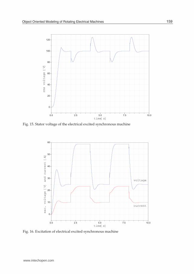
During starting the generator with turbineSpeed the excitation voltage and current as well asthe machine terminal voltage increase to no-load operation at nominal voltage. The overshotsare due to the settings of the voltage controller. Figure 14 shows the transient changes ofline current between no-load and nominal current due to loading and load dump. Theterminal voltage—see fig. 15—shows dips during loading and overshots during load dump.The voltage controller increases respectively decreases excitation voltage as shown in fig. 16.The excitation current follows the excitation voltage with a time constant according to totalexcitation inductance and excitation resistance.
6. Conclusions
The presented electric machines library, which it is part of the Modelica Standard Library,provides comprehensive three phase induction machine models. All relevant loss mechanismsare implemented and encapsulated in Modelica objects. The parametrized machine models
157Object Oriented Modeling of Rotating Electrical Machines
www.intechopen.com

Comment Parameter Value Unitnumber of pole pairs p 4
rotor’s moment of inertia Jr 0.29 kg · m2
nominal RMS voltage per phase VsNominal 100 Vnominal RMS current per phase 100 A
nominal frequency fsNominal 50 Hz
stator resistance Rs 0.03 Ω
stator stray inductance Lssigma 0.3183 mH
stator zero sequence inductance Lszero 0.3183 mHmain field inductance, d-axis Lmd 4.7746 mH
main field inductance, q-axis Lmq 4.7746 mH
damper stray inductance, d-axis Lrsigmad 0.1592 mHdamper stray inductance, d-axis Lrsigmaq 0.1592 mH
damper resistance, d-axis Rrd 0.04 Ω
damper resistance, q-axis Rrq 0.04 Ω
no-load excitation current IeOpenCircuit 10 A
excitation resistance Re 2.5 Ω
stray frac. of total exc. inductance sigmae 2.5 %
Table 4. Parameters of the electrical excited synchronous machine
0.0 2.5 5.0 7.5 10.0
0
20
40
60
80
100
time[stt]r ecun
Ai]cmn
Fig. 14. Current of electrical excited synchronous machine
158 Advances in Computer Science and Engineering
www.intechopen.com
0.0 2.5 5.0 7.5 10.0
0
20
40
60
80
100
120
rms voltage [V]
time[s]
Fig. 15. Stator voltage of the electrical excited synchronous machine
0.0 2.5 5.0 7.5 10.0
0
10
20
30
40
50
60
exc. voltage [V] and current [A]
time[s]
current
voltage
Fig. 16. Excitation of electrical excited synchronous machine
159Object Oriented Modeling of Rotating Electrical Machines
www.intechopen.com

can be used together with other models from the Modelica Standard Library for variousinvestigations; examples are presented in sec. 5. Due to the object oriented implementation allmachine models can be used as a basis to implement additional phenomena, such as magneticsaturation or deep bar effects. Since the physical connectors are standardized in the ModelicaStandard Library, the machine models have the potential to be used together with powerelectronic circuits, controll models and thermal models.
7. References
60034-2, D. E. (1998). Drehende elektrische Maschinen – Teil 2: Verfahren zur Bestimmungder Verluste und des Wirkungsgrades von drehenden elektrischen Maschinen ausPrüfungen (ausgenommen Maschinen für Schienen- und Straßenfahrzeuge.
60034-4, D. E. (1998). Drehende elektrische Maschinen – Teil 4: Verfahren zur Ermittlung derKenngrößen von Synchronmaschinen durch Messung.
Fritzson, P. (2004). Principles of Object-Oriented Modeling and Simulation with Modelica 2.1, IEEEPress, Piscataway, NJ.
Haumer, A., Bäuml, T. & Kral, C. (2010). Multiphysical simulation improves engineering ofelectric drives, 7th EUROSIM Congress on Modelling and Simulation .
Haumer, A., Kral, C., Kapeller, H., Bäuml, T. & Gragger, J. V. (2009). The AdvancedMachineslibrary: Loss models for electric machines, Proceedings of the 7th Modelica Conferencepp. 847–854.
Kleinrath, H. (1980). Stromrichtergespeiste Drehfeldmaschinen, Springer Verlag, Wien.Lang, W. (1984) Über die Bemessung verlustarmer Asynchronmotoren mit Kägläufer für
Pulsumrichterspeisung, PhD thesis, Technische Universität Wien.Lin, D., Zhou, P., Fu, W., Badics, Z. & Cendes, Z. (2003). A dynamic core loss model for
soft ferromagnetic and power ferrite materials in transient finite element analysis,Conference Proceedings COMPUMAG .
160 Advances in Computer Science and Engineering
www.intechopen.com

Advances in Computer Science and EngineeringEdited by Dr. Matthias Schmidt
ISBN 978-953-307-173-2Hard cover, 462 pagesPublisher InTechPublished online 22, March, 2011Published in print edition March, 2011
InTech EuropeUniversity Campus STeP Ri Slavka Krautzeka 83/A 51000 Rijeka, Croatia Phone: +385 (51) 770 447 Fax: +385 (51) 686 166www.intechopen.com
InTech ChinaUnit 405, Office Block, Hotel Equatorial Shanghai No.65, Yan An Road (West), Shanghai, 200040, China
Phone: +86-21-62489820 Fax: +86-21-62489821
The book Advances in Computer Science and Engineering constitutes the revised selection of 23 chapterswritten by scientists and researchers from all over the world. The chapters cover topics in the scientific fields ofApplied Computing Techniques, Innovations in Mechanical Engineering, Electrical Engineering andApplications and Advances in Applied Modeling.
How to referenceIn order to correctly reference this scholarly work, feel free to copy and paste the following:
Christian Kral and Anton Haumer (2011). Object Oriented Modeling of Rotating Electrical Machines, Advancesin Computer Science and Engineering, Dr. Matthias Schmidt (Ed.), ISBN: 978-953-307-173-2, InTech,Available from: http://www.intechopen.com/books/advances-in-computer-science-and-engineering/object-oriented-modeling-of-rotating-electrical-machines


![Object-oriented Programming with PHP · Object-oriented Programming with PHP [2 ] Object-oriented programming Object-oriented programming is a popular programming paradigm where concepts](https://static.fdocuments.us/doc/165x107/5e1bb46bfe726d12f8517bf0/object-oriented-programming-with-php-object-oriented-programming-with-php-2-object-oriented.jpg)