OB 12 Z-Domain Synthesizer - SynthDIY.com · Z-Domain Synthesizer OB 12 1. IMPORTANT NOTES 1.1...
127
OB 12 MANUALE OPERATIVO OPERATING MANUAL VISCOUNT JOINT VENTURE Oberheim Synthesizer Z-Domain
-
Upload
hoangkhanh -
Category
Documents
-
view
223 -
download
0
Transcript of OB 12 Z-Domain Synthesizer - SynthDIY.com · Z-Domain Synthesizer OB 12 1. IMPORTANT NOTES 1.1...

OB 12
MANUALE OPERATIVO
OPERATING MANUAL
VISCOUNT J O I N T V E N T U R E
Oberheim
SynthesizerZ-Domain


OB 12Z-Domain Synthesizer
CONTENTS
1. IMPORTANTS NOTES ........................................................................................................ 1251.1 NOTES ABOUT OB-12 ................................................................................................ 1251.2 NOTES ABOUT THE MANUAL ................................................................................... 125
2. MAIN CHARACTERISTICS ................................................................................................. 126
3. CONTROLS AND CONNECTORS...................................................................................... 1273.1 THE FRONT PANEL .................................................................................................... 1273.2 THE CONTROL CENTER SECTION........................................................................... 1293.3 THE REAR PANEL ...................................................................................................... 130
4. CONNECTIONS................................................................................................................. .. 1314.1 SPEAKERS AND MONITORS ..................................................................................... 1314.2 MIXING CONSOLE ...................................................................................................... 1324.3 MIDI UNITS .................................................................................................................. 132
5. HOW TO BE OB-12 IS ORGANISED ................................................................................. 1335.1 MAIN STRUCTURE ..................................................................................................... 1335.2 PROGRAM, TIMBRE AND SYSTEM ........................................................................... 1355.3 THE AUTOMATION SECTION .................................................................................... 138
6. PLAYING THE PROGRAMS AND TIMBRES ..................................................................... 1436.1 PLAY PROGRAM ......................................................................................................... 1436.2 PLAY TIMBRE .............................................................................................................. 145
7. USING THE PANEL ............................................................................................................. 1467.1 SETTING THE FIRST WAVEFORM (OSC.1) .............................................................. 1467.2 SETTING THE SECOND WAVEFORM (OSC.2) ......................................................... 1487.3 MODIFYING THE PARAMETERS COMMON TO OSC.1 AND OSC.2 (OSC.COMMON) . 1507.4 MODIFIYNG THE TIMBRE (FILTERS) ........................................................................ 1527.5 VOLUME CONTROL (AMPLIFIER) ............................................................................. 1557.6 MODULATION THE SOUND CYCLICALLY (LFO1) .................................................... 1567.7 MODULATING THE SOUND WITH THE [MODULATION] WHEEL (LFO2) ............... 1577.8 SETTING THE KEYBOARD (KEYBOARD) ................................................................. 1587.9 ADDING EFFECTS TO THE SOUND (EFFECTS) ...................................................... 1607.10 EQUALIZING THE SOUND (EQUALIZER) ............................................................... 1617.11 REGULATING THE GENERAL VOLUME (VOLUME) ............................................... 1627.12 USING THE [PITCH] AND [MOULATION] WHEELS ................................................. 1627.13 ENABLING THE VELOCITY AND AFTERTOUCH .................................................... 1637.14 USING THE RIBBON CONTROLLER ....................................................................... 163
8. EDIT TIMBRE ................................................................................................................. ..... 1648.1 EDIT OSCILLATOR 1 ................................................................................................... 1658.2 EDIT OSCILLATOR 2 ................................................................................................... 1688.3 EDIT OSCILLATOR COMMON .................................................................................... 1718.4 EDIT FILTERS.............................................................................................................. 1738.5 EDIT AMPLIFIER ......................................................................................................... 1798.6 EDIT LFO1 ................................................................................................................... 1818.7 EDIT LFO 2 .................................................................................................................. 1838.8 EDIT KEYBOARD MODE............................................................................................. 184
123

OB 12 Z-Domain Synthesizer
8.9 EDIT CONTROLLERS ................................................................................................. 1868.10 WRITE TIMBRE ......................................................................................................... 191
9. EDIT PROGRAM ................................................................................................................ . 1929.1 EDIT PART SETTINGS ................................................................................................ 1939.2 BUS SETTINGS ........................................................................................................... 1949.3 EDIT EFFECTS ............................................................................................................ 1949.4 EDIT EQUALIZER ........................................................................................................ 1999.5 LINKS ........................................................................................................................... 2009.6 FOOT CONTROL SETUP............................................................................................ 2019.7 ARPEGGIO SETTINGS ............................................................................................... 2049.8 PHRASE RECORDER ................................................................................................. 2079.9 AUTO - MANUAL MORPH ........................................................................................... 2139.10 KEYBOARD TRANSPOSE ........................................................................................ 2149.11 MOTION RECORDER ................................................................................................ 2159.12 WRITE PROGRAM .................................................................................................... 221
10. EDIT SYSTEM ................................................................................................................... 22210.1 MIDI COMMON .......................................................................................................... 22210.2 MIDI CONTROLS ....................................................................................................... 22510.3 MIDI SYNC ................................................................................................................. 22810.4 BULK DUMP............................................................................................................... 23110.5 FOOT CONTROL SETUP.......................................................................................... 23210.6 DIGITAL OUTPUT SETTINGS................................................................................... 23410.7 GLOBAL SETUP ........................................................................................................ 23510.8 TOOLS ....................................................................................................................... 236
11. APPENDIX ................................................................................................................... ...... 23911.1 SOFTWARE INSTALLATION ..................................................................................... 23911.2 ERROR MESSAGES .................................................................................................. 24011.3 MIDI ............................................................................................................................ 24111.4 BLOCK DIAGRAM ...................................................................................................... 243
124

OB 12Z-Domain Synthesizer
1. IMPORTANT NOTES
1.1 NOTES ABOUT OB-12
1.2 NOTES ABOUT the MANUAL
125
LOOKING AFTER THE PRODUCT
• Do not apply excessive force to the structures and controls (knobs, switches).• Protect the instrument from stresses both in transit and in use. The instrument should be
transported in its original packaging or equivalent wrapping.• Do not place the OB-12 close to sources of heat, in damp or dusty places or in the vicinity of
strong magnetic fields.• When possible, do not place the instrument close to units which produce strong interference
such as radios, TV sets, monitors, etc...• Do not insert foreign bodies or liquids of any kind inside the equipment.• For cleaning, use only a soft cloth or compressed air; never use detergents, solvents or
alcohol.• Do not expose the instrument to direct sunlight.• Do not hit the display or apply excessive force to it.
CONNECTING TO THE ELECTRICAL MAINS
• To avoid the risk of electric shock, do not make the connections with wet hands.• Make sure that the mains voltage is as indicated on the lower panel.
CONNECTING TO OTHER INSTRUMENTS
• Always use good quality screened cables. When disconnecting cables from sockets, alwaystake hold of the connector and not the cable itself; when coiling them, do not allow knots ortwists to form.
• Before making the connections ensure that the other units (especially amplification and diffusionsystems) you are about to connect are switched off. This will prevent noisy or even hazardoussignal peaks.
• Take good care of this manual.• Read all the information provided in this manual carefully. You will avoid wasting time and will
obtain the best performance from your instrument.• Codes or numbers in square brackets ([]) refer to the names of buttons, sliders or trimmers on
the instrument panel.For example, [RATE] means the RATE trimmer.
• Illustrations and display pages are for information only and may differ from those actuallyshown on the LCD.
OB 12 Z-Domain Synthesizer
2. MAIN CHARACTERISTIC
126
REAL-TIME CONTROL EFFECTIVENESS
The OB-12 is a synthesizer designed to be fully controllable in real time, the main feature of thefamous analog synthesizers. And the huge advantage this provides is a user-friendliness whichwas perhaps being lost with the latest digital synthesizers, with programming procedures toocomplex for many people to attempt. However, this does not mean the OB-12 offers limitedpotential. You will realise this as you read this manual and use the instrument.
As well as giving an “analog feeling”, the OB-12, also uses the most sophisticated digital technologyfor signal generation and processing.
We said “analog feeling”, because the OB-12 is the natural evolution of the analog synthesizerswhich have shaped the history of music. Although not perfect (limited storage capacity, unstabletuning and limited polyphony) due to their analog nature itself, these synthesizers were controlledby means of a vast number of knobs which made them extremely easy to use.With the advent of digital synthesizers, this ease of use has been lost somewhat, as all the generationcontrols have been shifted into software programming pages.
The OB-12 has been developed to combine this user-friendliness with the best sound generationand processing technologies. The front panel is subdivided into various sections, containing thecontrols dedicated to the various blocks of the generation chain.
TOTAL MEMORISATION
The OB-12 offers the user 256 Programs, all modifiable and memorisable. Each Program cancontain up to 4 parts (so that you can divide the keyboard into 4 zones), each with a differenttimbre. In addition to this, the instrument also offers 256 Timbres, also totally modifiable andmemorisable.
AUTOMATION
The OB-12 offers automated systems for the most widely varying functions. For example, youcan make use of a completely configurable arpeggio and a Phrase Recorder in which you canmemorise musical phrases ready for recall by pressing a keyboard key.You can also use a Motion Recorder in which you can memorise specific motions of the panelcontrols, which can all be repeated at the touch of a button, and a Morphing function, enablingyou to trasform a sound to another and to listen to all the continuous variations as you do so.
CONTROLS
As well as the usual trimmers and buttons for control of sound generation, the OB-12 allows youto use [PITCH] and [MODULATION] wheels for real-time control of the tuning of the timbres (thefirst) and the depth of modulation by the LFO 2, the Morph or the parameters assigned to Aftertouch(the second).What’s more, there is also a Ribbon Controller; after assigning the various generation parametersto this controller, you can then control them by just running a finger over its surface.

OB 12Z-Domain Synthesizer
3. CONTROLS and CONNECTORS
3.1 The FRONT PANEL
127
1. LFO 1 sectionThis section of the front panel contains the controls relating to the LFO 1 (Low Frequency Oscillator1). The LFO 1 is the first low frequency oscillator in the generation chain, capable of generatinga waveform which modulates the sound cyclically.
2. OSCILLATOR COMMON sectionHere you will find the controls for the common settings of the OSCILLATOR 1 and OSCILLATOR2 sections. These controls allow you to set the envelope of the oscillators and their balancing(since they are able to generate two different waveforms) to control the tuning of the sound.
3. OSCILLATOR 1 sectionThese controls allow you to set the characteristics of the first oscillator for generation of the firstbasic waveform (which however, will already be complex) of the sound you are about to create.
4. OSC 1 PARAM (Oscillator 1 Parameter) sectionThis section describes the functions of the [WAVE CTRL] control knob in the OSCILLATOR 1section.
5. OSCILLATOR 2 sectionAs for the OSC 1 section, here you can set the characteristics of the second waveform which isthe basis of the sound generated by the second oscillator.
6. FILTERS sectionThis section contains the controls relating to the characteristics (envelope, cut-off frequency andresonance, to name the most significant) of the filter, i.e. the combination of FILTER 1 and FILTER2, by means of which you can modify the brightness of the sound over time.
7. AMPLIFIER sectionHere you can set the characteristics of the amplifier used to regulate the level of the sound overtime.
OB 12 Z-Domain Synthesizer
128
1. LFO 2 sectionThis section contains the controls relating to the settings of the second low frequency oscillator,controllable by means of the wheel on the left of the keyboard, marked [MODULATION].
2. KEYBOARD sectionHere you can adjust a number of parameters relating to the keyboard, including the performancemode, enabling of the Portamento or Unison status and transposition of the oscillators by octaves.
10. EFFECTS sectionHere you can enable and set the level of a parameter (assigned by means of the programmingpages) of the four effects offered by the OB-12, i.e. Overdrive, Chorus, Delay and Reverb.
11. ARPEGGIO sectionHere you can activate and set the basic characteristics of the function used to arpeggio chords orsingle notes being played on the keyboard.
12. PHRASE sectionThis section allows you to enable and set the PHRASE RECORDER system, used to record amusical phrase and repeat it (or play phrases already memorised) at the touch of a keyboard key.
13. CONTROL CENTER sectionThis section contains all the commands for display operations, for assignment of parts to thekeyboard and for the MOTION and MORPH functions. See point 3.2 – CONTROL CENTER Sectionfor further information.
14. EQUALIZER sectionThis section allows equalisation of the sound using an equaliser which can be configured asgraphic or parametric.
15. VOLUME sectionThis section contains the [MASTER VOLUME] slider for control of the instrument’s overall volume.
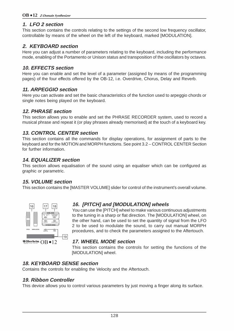
16. [PITCH] and [MODULATION] wheelsYou can use the [PITCH] wheel to make various continuous adjustmentsto the tuning in a sharp or flat direction. The [MODULATION] wheel, onthe other hand, can be used to set the quantity of signal from the LFO2 to be used to modulate the sound, to carry out manual MORPHprocedures, and to check the parameters assigned to the Aftertouch.
17. WHEEL MODE sectionThis section contains the controls for setting the functions of the[MODULATION] wheel.
18. KEYBOARD SENSE sectionContains the controls for enabling the Velocity and the Aftertouch.
19. Ribbon ControllerThis device allows you to control various parameters by just moving a finger along its surface.
OB 12Z-Domain Synthesizer
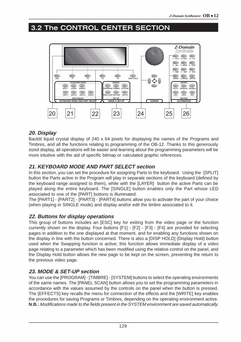
20. DisplayBacklit liquid crystal display of 240 x 64 pixels for displaying the names of the Programs andTimbres, and all the functions relating to programming of the OB-12. Thanks to this generouslysized display, all operations will be easier and learning about the programming parameters will bemore intuitive with the aid of specific bitmap or calculated graphic references.
21. KEYBOARD MODE AND PART SELECT sectionIn this section, you can set the procedure for assigning Parts to the keyboard. Using the [SPLIT]button the Parts active in the Program will play in separate sections of the keyboard (defined bythe keyboard range assigned to them), while with the [LAYER] button the active Parts can beplayed along the entire keyboard. The [SINGLE] button enables only the Part whose LEDassociated to one of the [PART] buttons is illuminated.The [PART1] - [PART2] - [PART3] - [PART4] buttons allow you to activate the part of your choice(when playing in SINGLE mode) and display and/or edit the timbre associated to it.
22. Buttons for display operationsThis group of buttons includes an [ESC] key for exiting from the video page or the functioncurrently shown on the display. Four buttons [F1] - [F2] - [F3] - [F4] are provided for selectingpages in addition to the one displayed at that moment, and for enabling any functions shown onthe display in line with the button concerned. There is also a [DISP HOLD] (Display Hold) buttonused when the Swapping function is active; this function allows immediate display of a videopage relating to a parameter which has been modified using the relative control on the panel, andthe Display Hold button allows the new page to be kept on the screen, preventing the return tothe previous video page.
23. MODE & SET-UP sectionYou can use the [PROGRAM] - [TIMBRE] - [SYSTEM] buttons to select the operating environmentsof the same names. The [PANEL SCAN] button allows you to set the programming parameters inaccordance with the values assumed by the controls on the panel when the button is pressed.The [EFFECTS] key recalls the menu for connection of the effects and the [WRITE] key enablesthe procedures for saving Programs or Timbres, depending on the operating environment active.N.B.: Modifications made to the fields present in the SYSTEM environment are saved automatically.
3.2 The CONTROL CENTER SECTION
129

OB 12 Z-Domain Synthesizer
3.3 The REAR PANEL
130
24. Rotary encoder and [CURSOR] keysThe rotary dynamic Encoder allows you to select the Program or Timbre of your choice, to increaseor decrease the value of the parameter currently selected or to position the cursor on the chosenfield in the option selection menu (e.g. in the Edit Program Menu). The [CURSOR] keys providethe same cursor positioning function.
25. Number keypadNumber keypad for entering the values of parameters or for typing the names of Programs andTimbres during saving operations. You will press the [ENTER] button to confirm settings made orto start procedures when the system prompts this. There is also a [BANK] button for selecting theProgram or Timbre memory bank, and + and – signs for entering number values where negativeand positive values are present.
26. AUTOMATION sectionThis section actually contains two different functions. The first relates to the Morph, meaning thepossibility of passing from one Program or Timbre to another in a programmable period of time orusing the [MODULATION] wheel, while the second relates to the Motion, or two memory locationsin which all the movements carried out on the panel controls over a given period of time can berecorded. You can use [AUTO] and [MANUAL] buttons to recall the automatic or manual Morphfunctions, while the [ENABLE] key allows you to start the procedure concerned.The [LOC1] and [LOC2] can be used to recall one of the two Motion Locations, while the [REC]key enables recording of the movements of the panel controls.
27. [POWER] switchSwitch used for turning the OB-12 on and off.
28. [AC INPUT] connectorConnect the power supply lead provided with the instrument to this connector.
29. MIDI connectorsConnect the MIDI units you wish to use together with the OB-12 to these connectors.The MIDI [OUT] connector sends the MIDI messages generated by the OB-12, while the MIDI[THRU] connector sends the MIDI codes received by the MIDI [IN] port, i.e the input port for MIDImessages generated by a remote MIDI unit.
30. PEDALS connectorConnect the leads from remote pedals to which you have assigned functions by means of the
OB 12Z-Domain Synthesizer
4. CONNECTIONS
4.1 SPEAKERS and MONITORS
131
internal programming parameters to these connectors. Connect expression pedals to the [EXP.1](Expression 1) and [EXP.2] (Expression 2) connectors, and footswitch pedals to the [SWITCH1]and [SWITCH2] ports.
31. [DIGITAL OUTPUT] connectorYou can use this socket to collect the digital signal generated by the OB-12 in order to connectthe instrument to DATs, digital mixers, CD mastering units, etc..
32. AUX OUT connectorsExtra connectors from which the analog signal generated by the OB-12 can be collected.
33. MAIN OUT connectorsMain connectors from which the analog stereophonic signal produced by the OB-12 can becollected. If you are using a monophonic unit for amplifying or recording the signal, connect the[L/MONO] connector only.
34. PHONES connectorYou can connect a set of headphones to this connector in order to monitor the sound of the OB-12 without the aid of amplified monitors. The signal will still be present at the [MAIN] and [AUX]outputs.
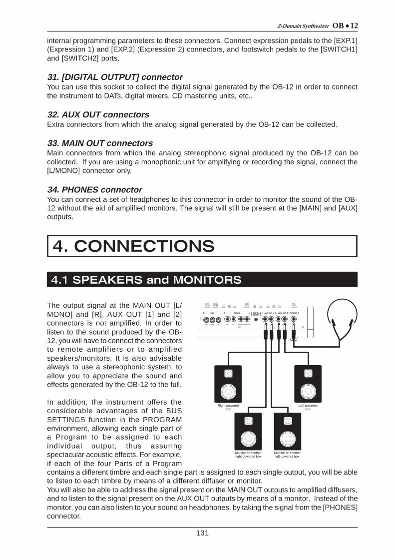
The output signal at the MAIN OUT [L/MONO] and [R], AUX OUT [1] and [2]connectors is not amplified. In order tolisten to the sound produced by the OB-12, you will have to connect the connectorsto remote amplifiers or to amplifiedspeakers/monitors. It is also advisablealways to use a stereophonic system, toallow you to appreciate the sound andeffects generated by the OB-12 to the full.
In addition, the instrument offers theconsiderable advantages of the BUSSETTINGS function in the PROGRAMenvironment, allowing each single part ofa Program to be assigned to eachindividual output, thus assuringspectacular acoustic effects. For example,if each of the four Parts of a Programcontains a different timbre and each single part is assigned to each single output, you will be ableto listen to each timbre by means of a different diffuser or monitor.You will also be able to address the signal present on the MAIN OUT outputs to amplified diffusers,and to listen to the signal present on the AUX OUT outputs by means of a monitor. Instead of themonitor, you can also listen to your sound on headphones, by taking the signal from the [PHONES]connector.

OB 12 Z-Domain Synthesizer
4.2 MIXING CONSOLE
4.3 MIDI UNITS
132
Connecting the OB-12 to a mixing console will allow youto obtain excellent advantages, with the possibility ofusing four outputs. For example, you can address theMAIN OUT connectors to two channels (or to one stereochannel) and the AUX OUT connectors to two differentchannels, so that the signals on the outputs can beprocessed differently. This solution is especially usefulwhen, for example, you wish to process the individualParts of a Program differently from each other.
The OB-12 can be MIDI-connected to MasterKeyboards, Sequencers, another synthesizer, or aPersonal Computer MIDI interface, thus allowing theuse of the most sophisticated musical softwares (writingof scores, saving and editing of musical patterns, realtime controls by PC of the OB-12 internal parameters,etc.).
OB 12Z-Domain Synthesizer
5. HOW TO BE OB-12 IS ORGANISED
5.1 MAIN STRUCTURE
133
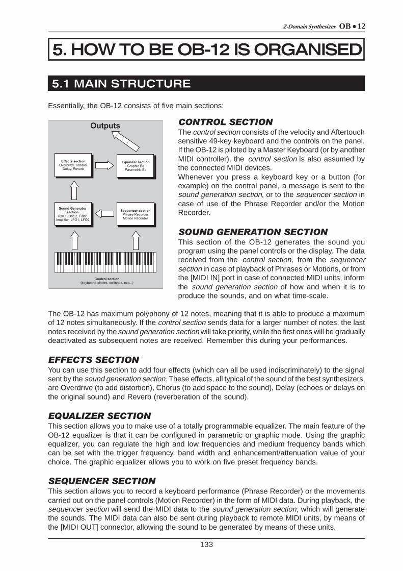
Essentially, the OB-12 consists of five main sections:
CONTROL SECTIONThe control section consists of the velocity and Aftertouchsensitive 49-key keyboard and the controls on the panel.If the OB-12 is piloted by a Master Keyboard (or by anotherMIDI controller), the control section is also assumed bythe connected MIDI devices.Whenever you press a keyboard key or a button (forexample) on the control panel, a message is sent to thesound generation section, or to the sequencer section incase of use of the Phrase Recorder and/or the MotionRecorder.
SOUND GENERATION SECTIONThis section of the OB-12 generates the sound youprogram using the panel controls or the display. The datareceived from the control section, from the sequencersection in case of playback of Phrases or Motions, or fromthe [MIDI IN] port in case of connected MIDI units, informthe sound generation section of how and when it is toproduce the sounds, and on what time-scale.
The OB-12 has maximum polyphony of 12 notes, meaning that it is able to produce a maximumof 12 notes simultaneously. If the control section sends data for a larger number of notes, the lastnotes received by the sound generation section will take priority, while the first ones will be graduallydeactivated as subsequent notes are received. Remember this during your performances.
EFFECTS SECTIONYou can use this section to add four effects (which can all be used indiscriminately) to the signalsent by the sound generation section. These effects, all typical of the sound of the best synthesizers,are Overdrive (to add distortion), Chorus (to add space to the sound), Delay (echoes or delays onthe original sound) and Reverb (reverberation of the sound).
EQUALIZER SECTIONThis section allows you to make use of a totally programmable equalizer. The main feature of theOB-12 equalizer is that it can be configured in parametric or graphic mode. Using the graphicequalizer, you can regulate the high and low frequencies and medium frequency bands whichcan be set with the trigger frequency, band width and enhancement/attenuation value of yourchoice. The graphic equalizer allows you to work on five preset frequency bands.
SEQUENCER SECTIONThis section allows you to record a keyboard performance (Phrase Recorder) or the movementscarried out on the panel controls (Motion Recorder) in the form of MIDI data. During playback, thesequencer section will send the MIDI data to the sound generation section, which will generatethe sounds. The MIDI data can also be sent during playback to remote MIDI units, by means ofthe [MIDI OUT] connector, allowing the sound to be generated by means of these units.
OB 12 Z-Domain Synthesizer
134
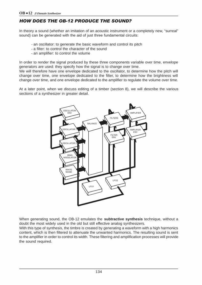
HOW DOES THE OB-12 PRODUCE THE SOUND?
In theory a sound (whether an imitation of an acoustic instrument or a completely new, “surreal”sound) can be generated with the aid of just three fundamental circuits:
- an oscillator: to generate the basic waveform and control its pitch- a filter: to control the character of the sound- an amplifier: to control the volume
In order to render the signal produced by these three components variable over time, envelopegenerators are used: they specify how the signal is to change over time.We will therefore have one envelope dedicated to the oscillator, to determine how the pitch willchange over time, one envelope dedicated to the filter, to determine how the brightness willchange over time, and one envelope dedicated to the amplifier to regulate the volume over time.
At a later point, when we discuss editing of a timber (section 8), we will describe the varioussections of a synthesizer in greater detail.
When generating sound, the OB-12 emulates the subtractive synthesis technique, without adoubt the most widely used in the old but still effective analog synthesizers.With this type of synthesis, the timbre is created by generating a waveform with a high harmonicscontent, which is then filtered to attenuate the unwanted harmonics. The resulting sound is sentto the amplifier in order to control its width. These filtering and amplification processes will providethe sound required.

OB 12Z-Domain Synthesizer
5.2 PROGRAM, TIMBRE and SYSTEM
135
The internal memory is mainly subdivided into four large sections:
1. the memory section reserved for the PROGRAMS (and thus the PROGRAM operatingenvironment)
2. the memory section reserved for the TIMBRES (TIMBRE operating environment)3. the memory section reserved for the SYSTEM UTILITIES (SYSTEM operating environment)4. the AUTOMATION section, comprising the ARPEGGIO, PHRASE RECORDER and MOTION
RECORDER functions.
We will now take a detailed look at the first three sections.
THE PROGRAMSThe OB-12 contains 256 Programs, 128 in bank A and 128 in bank B, completely programmableand all memorisable.A Program can be set with up to four Parts containing one Timbre each, and offers the possibilityof configuration with four different timbres. Naturally, this example is purely guideline, since it isnot always necessary to set a Program with four parts and thus with four different timbres.As well as containing the Timbres, the Program also allows the addition of effects and equalizationof the sound generated by the timbres, regulation and performance of arpeggios, configurationof the outputs, and other useful functions which we will be looking at later.
Refer to section 9 of this manual for all necessary information about the Programs. In addition,section 7 describes the panel controls of the sections associated to the Programs (Effects,Arpeggio, Phrase Recorder and Equalizer).You can access the PROGRAM operating environment (which is also preselected when theinstrument is switched on) by pressing the [PROGRAM] button in the MODE&SET-UP section ofthe central panel. Once the selection has been made, the LED of the key illuminates and thefollowing video page appears in confirmation:
THE TIMBRESA Timbre is the basis of the sound you produce using the Program. However, while you cannotplay a Program unless it contains at least one Timbre, the Timbre itself can be played on its own,regardless of the Program settings, by enabling the Timbre operating environment.The OB-12 memory contains 256 Timbres, 128 in bank A and 128 in bank B. The internal structureof the Timbre is essentially as shown below:
As the diagram in the next page shows, this generation chain consists of four main components:
- OSC.1 and OSC.2: which generate the two waveforms (which as we will see, can be theresult of three signals for each oscillator);
- FILTERS: programmable combination of two filters which attenuate the unwanted harmonicsof the signals produced by the oscillators, and thus control the brightness of the sound;
- AMPLIFIER: which controls the level of the signal leaving the filters:
and then by a further five sections which control the four main ones:
OB 12 Z-Domain Synthesizer
136
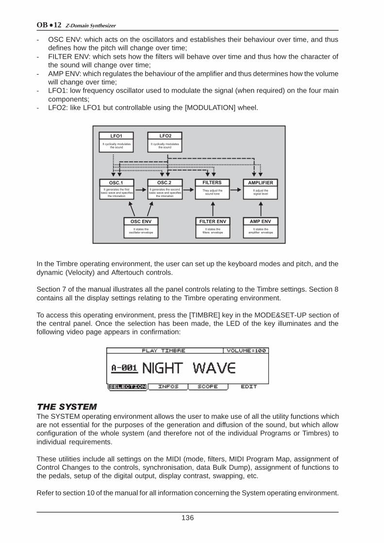
- OSC ENV: which acts on the oscillators and establishes their behaviour over time, and thusdefines how the pitch will change over time;
- FILTER ENV: which sets how the filters will behave over time and thus how the character ofthe sound will change over time;
- AMP ENV: which regulates the behaviour of the amplifier and thus determines how the volumewill change over time;
- LFO1: low frequency oscillator used to modulate the signal (when required) on the four maincomponents;
- LFO2: like LFO1 but controllable using the [MODULATION] wheel.
In the Timbre operating environment, the user can set up the keyboard modes and pitch, and thedynamic (Velocity) and Aftertouch controls.
Section 7 of the manual illustrates all the panel controls relating to the Timbre settings. Section 8contains all the display settings relating to the Timbre operating environment.
To access this operating environment, press the [TIMBRE] key in the MODE&SET-UP section ofthe central panel. Once the selection has been made, the LED of the key illuminates and thefollowing video page appears in confirmation:
THE SYSTEMThe SYSTEM operating environment allows the user to make use of all the utility functions whichare not essential for the purposes of the generation and diffusion of the sound, but which allowconfiguration of the whole system (and therefore not of the individual Programs or Timbres) toindividual requirements.
These utilities include all settings on the MIDI (mode, filters, MIDI Program Map, assignment ofControl Changes to the controls, synchronisation, data Bulk Dump), assignment of functions tothe pedals, setup of the digital output, display contrast, swapping, etc.
Refer to section 10 of the manual for all information concerning the System operating environment.

OB 12Z-Domain Synthesizer
137
To access this operating environment, press the [SYSTEM] button in the MODE&SET-UP sectionof the central panel. Once the selection has been made, the LED of the key illuminates and thefollowing video page appears in confirmation:
THE DISPLAY SWAPPING FUNCTIONAs we will see below, the OB-12 has a huge number of parameters and controls on the frontpanel, used to generate the type of sound desired. It may often occur that when the Play Programvideo page is displayed (i.e. not the Program editing video pages) the user wishes to modify agiven control on the panel, and check the value associated to it, without switching from theProgram to the Timbre operating environment for the purpose. At other times, it may useful todisplay a timbre editing page immediately by just moving a control on the panel, without having tocarry out the entire display procedure to obtain display of the video page concerned.
The DISPLAY SWAPPING function allows the user to display a given menu page by just changingthe position of a control whose parameter is present in the video page. This means that the videopage can be displayed momentarily (to check the value of the parameter whose panel control isbeing used) or the user can “freeze” it and then move around the menus relating to the videopage displayed by simply pressing the [DISP HOLD] (Display Hold) button in the Control Centersection of the front panel.
The OB-12 also allows the user to set the Display Swapping function to his own requirements, inorder to obtain the best from this important, useful function.After pressing the [SYSTEM] button, select option 7-GLOBAL SETUP. The display will show:
now select the SWAPPING folder to access the function set-up:
OB 12 Z-Domain Synthesizer
5.3 The AUTOMATION SECTION
138
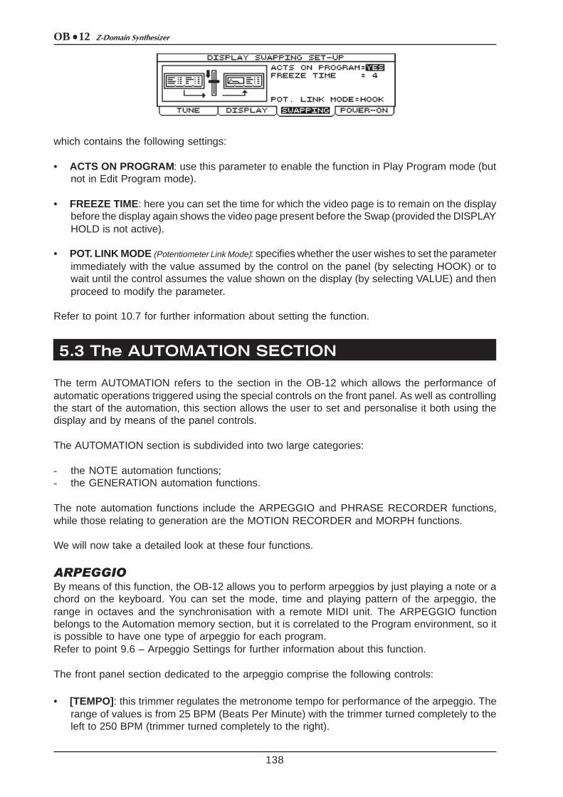
which contains the following settings:
• ACTS ON PROGRAM: use this parameter to enable the function in Play Program mode (butnot in Edit Program mode).
• FREEZE TIME: here you can set the time for which the video page is to remain on the displaybefore the display again shows the video page present before the Swap (provided the DISPLAYHOLD is not active).
• POT. LINK MODE (Potentiometer Link Mode): specifies whether the user wishes to set the parameterimmediately with the value assumed by the control on the panel (by selecting HOOK) or towait until the control assumes the value shown on the display (by selecting VALUE) and thenproceed to modify the parameter.
Refer to point 10.7 for further information about setting the function.
The term AUTOMATION refers to the section in the OB-12 which allows the performance ofautomatic operations triggered using the special controls on the front panel. As well as controllingthe start of the automation, this section allows the user to set and personalise it both using thedisplay and by means of the panel controls.
The AUTOMATION section is subdivided into two large categories:
- the NOTE automation functions;- the GENERATION automation functions.
The note automation functions include the ARPEGGIO and PHRASE RECORDER functions,while those relating to generation are the MOTION RECORDER and MORPH functions.
We will now take a detailed look at these four functions.
ARPEGGIOBy means of this function, the OB-12 allows you to perform arpeggios by just playing a note or achord on the keyboard. You can set the mode, time and playing pattern of the arpeggio, therange in octaves and the synchronisation with a remote MIDI unit. The ARPEGGIO functionbelongs to the Automation memory section, but it is correlated to the Program environment, so itis possible to have one type of arpeggio for each program.Refer to point 9.6 – Arpeggio Settings for further information about this function.
The front panel section dedicated to the arpeggio comprise the following controls:
• [TEMPO] : this trimmer regulates the metronome tempo for performance of the arpeggio. Therange of values is from 25 BPM (Beats Per Minute) with the trimmer turned completely to theleft to 250 BPM (trimmer turned completely to the right).
OB 12Z-Domain Synthesizer
139
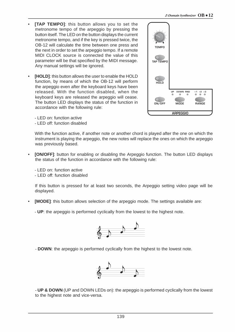
• [TAP TEMPO] : this button allows you to set themetronome tempo of the arpeggio by pressing thebutton itself. The LED on the button displays the currentmetronome tempo, and if the key is pressed twice, theOB-12 will calculate the time between one press andthe next in order to set the arpeggio tempo. If a remoteMIDI CLOCK source is connected the value of thisparameter will be that specified by the MIDI message.Any manual settings will be ignored.
• [HOLD] : this button allows the user to enable the HOLDfunction, by means of which the OB-12 will performthe arpeggio even after the keyboard keys have beenreleased. With the function disabled, when thekeyboard keys are released the arpeggio will cease.The button LED displays the status of the function inaccordance with the following rule:
- LED on: function active- LED off: function disabled
With the function active, if another note or another chord is played after the one on which theinstrument is playing the arpeggio, the new notes will replace the ones on which the arpeggiowas previously based.
• [ON/OFF]: button for enabling or disabling the Arpeggio function. The button LED displaysthe status of the function in accordance with the following rule:
- LED on: function active- LED off: function disabled
If this button is pressed for at least two seconds, the Arpeggio setting video page will bedisplayed.
• [MODE]: this button allows selection of the arpeggio mode. The settings available are:
- UP: the arpeggio is performed cyclically from the lowest to the highest note.
- DOWN: the arpeggio is performed cyclically from the highest to the lowest note.
- UP & DOWN (UP and DOWN LEDs on): the arpeggio is performed cyclically from the lowestto the highest note and vice-versa.

OB 12 Z-Domain Synthesizer
140
- RANDOM (RND): the arpeggio notes are played at random.
• [RANGE] : this button allows you to set the range in octaves of the arpeggio. The rangesavailable are:
- +1: arpeggio range two octaves.- +2: arpeggio range three octaves.- +3: arpeggio range four octaves.- no LED on : the range of the arpeggio is limited to the notes played. If just one note isplayed, no arpeggio will be performed; the note itself will simply be repeated.
THE PHRASE RECORDERThe PHRASE RECORDER is another automated function. Using this function, once a keyboardkey (pilot key) is pressed, the OB-12 performs a musical phrase recorded previously, continuingto play it in a loop until the key concerned is released (provided the HOLD function is not active).The OB-12 allows recording of up to four Sets of musical phrases, each with maximum capacityof 16000 notes and minimum resolution of 96 t.p.q.n.The MIDI data relating to the Phrase being played will be transmitted on the MIDI [OUT] port(except for any filters enabled for the note messages).Point 9.7 describes all the display procedures relating to this function.
N.B.: The ARPEGGIO and PHRASE RECORDER automation functions are mutually exclusive,so if the Arpeggio is active and the Phrase Recorder is selected the former is disabled, and vice-versa.
The panel section dedicated to the Phrase Recorder comprise the following controls:
• [TEMPO] : this trimmer allows you to regulate the metronome tempofor performance of the arpeggio. The range of values is from 25BPM (Beats Per Minute) with the trimmer turned completely to theleft to 250 BPM, with the trimmer turned completely to the right.
• [TAP TEMPO] : as for the Arpeggio, this button allows you to setthe metronome tempo for performance of the musical sequence.The LED on the button displays the current metronome tempo,and if the key is pressed twice, the OB-12 will calculate the timebetween one press and the next in order to set the tempo forperformance of the musical phrase. If a remote MIDI CLOCK sourceis connected the value of this parameter will be that specified bythe MIDI message. Any manual settings will be ignored.

OB 12Z-Domain Synthesizer
141
• [ON/OFF]: this button allows you to activate or deactivate the Phrase Recorder function. Thestatus of the function will be displayed by the LED on the button concerned in accordancewith the following rule:
- LED on: function active- LED off: function disabled
When the button is kept pressed for at least two seconds, the display will show the video pagecontaining the parameters for performance of the phrases.
• [REC] : this key enables the Record Phrase function, used to record a musical phrase. AnEvent Editor is also available for displaying and modifying the data contained in a Phrase.When the key is pressed, the LED illuminates and the OB-12 presets for recording of themusical sequence, showing the video pages for the function on the display.
• [HOLD] (of the ARPEGGIO section): this button provides the same function as for theARPEGGIO automation function. The LED displays the function status following the usualrule:
- LED on: function active- LED off: function disabled
When this function is enabled, the musical phrase the OB-12 is playing will continue to beperformed even when the keyboard key enabled to Start the Phrase (pilot key) is released.When another pilot key is pressed, the phrase associated to it will be played instead of theprevious one.
THE MOTION RECORDERThe MOTION RECORDER function allows the user to record and repeat movements of trimmersor sliders on the OB-12 front panel. This enables you to vary the sound continuously withoutmoving the controls on the panel.The data relating to the movements of the controls on the panel can be recorded in two memorylocations (Motion Location 1 and Motion Location 2) independent from the Program; each ofthem is able to contain two minutes of recording, i.e. 16000 events with resolution of 96 t.p.q.n.Refer to point 9.10 for further information relating to this function.
The panel selection relative to this automated function containing the commands:
• [LOC 1] : this button is pressed to start the sequencerecorded in Motion Location 1. The LED of the keyconcerned will illuminate and remain constantly on, witha small break at the end of each loop. When the key ispressed again, the repetition will stop and the LED willgo out.
• [LOC 2] : this button is pressed to start the sequencerecorded in Motion Location 2. The LED of the key concerned will illuminate and remainconstantly on, with a small break at the end of each loop. When the key is pressed again, therepetition will stop and the LED will go out.
• [REC] : this button is pressed to start the recording (Record Motion) procedure, or the procedurefor displaying or modifying the events contained in a Motion (Motion Event Editor), with displayof the pages relating to the procedures and the recording parameters.

OB 12 Z-Domain Synthesizer
142
The PHRASE RECORDER section [TEMPO] trimmer and [TAP TEMPO] button can be used toregulate the metronome tempo for repetition of the Motion. If the Phrase Recorder is alreadyactive, the Motion repetition tempo will be affected by the values set for the Phrase Recorder.
THE MORPHYou can use the MORPH automated function to move from a starting Program to another(destination) Program in a period of time which can be programmed or controlled using the[MODULATION] wheel, during which all the parameters which differ in the two Programs areinterpolated (i.e. varied continuously).Point 9.8 of this manual describes all the display procedures for programming this function.
To Morph Programs or Timbres, simply select the operating environment associated to them bypressing the [PROGRAM] and [TIMBRE] buttons in the front panel MODE&SET-UP section.
The Morph section comprises three buttons:
• [AUTO] : button used to enable the automatic Morph,which will be displayed by illumination of the buttonLED. When the relative key is pressed again, thefunction is disabled and the LED goes out.
• [MANUAL] : button used to enable the manual Morphfunction; the button LED then illuminates to displaythe selection made. Pressing the button again disablesthe automatic function and the LED goes out.
• [ENABLE] : key pressed to start the Morph function (automatic or manual). Pressing the buttonagain will interrupt or restart the Morph.
N.B.: If no manual or automatic Morphs have been selected, pressing the [ENABLE] button hasno effect.
OB 12Z-Domain Synthesizer
6. PLAYING the PROGRAMS andTIMBRES
6.1 PLAY PROGRAM
Keyboard Transpose
143
Once the connections have been made, follow these simple rules to switch on the instrument, inorder to prevent malfunctions and/or damage to the OB-12 and the connected instruments:
Check that the OB-12 is correctly connected to the rest of the system.Check that the amplification and diffusion systems are switched off.Set the OB-12 volume ([MASTER VOLUME] trimmer) at the minimum level.Turn on the instrument using the [POWER] switch.Turn on the amplification system and the diffusion system.
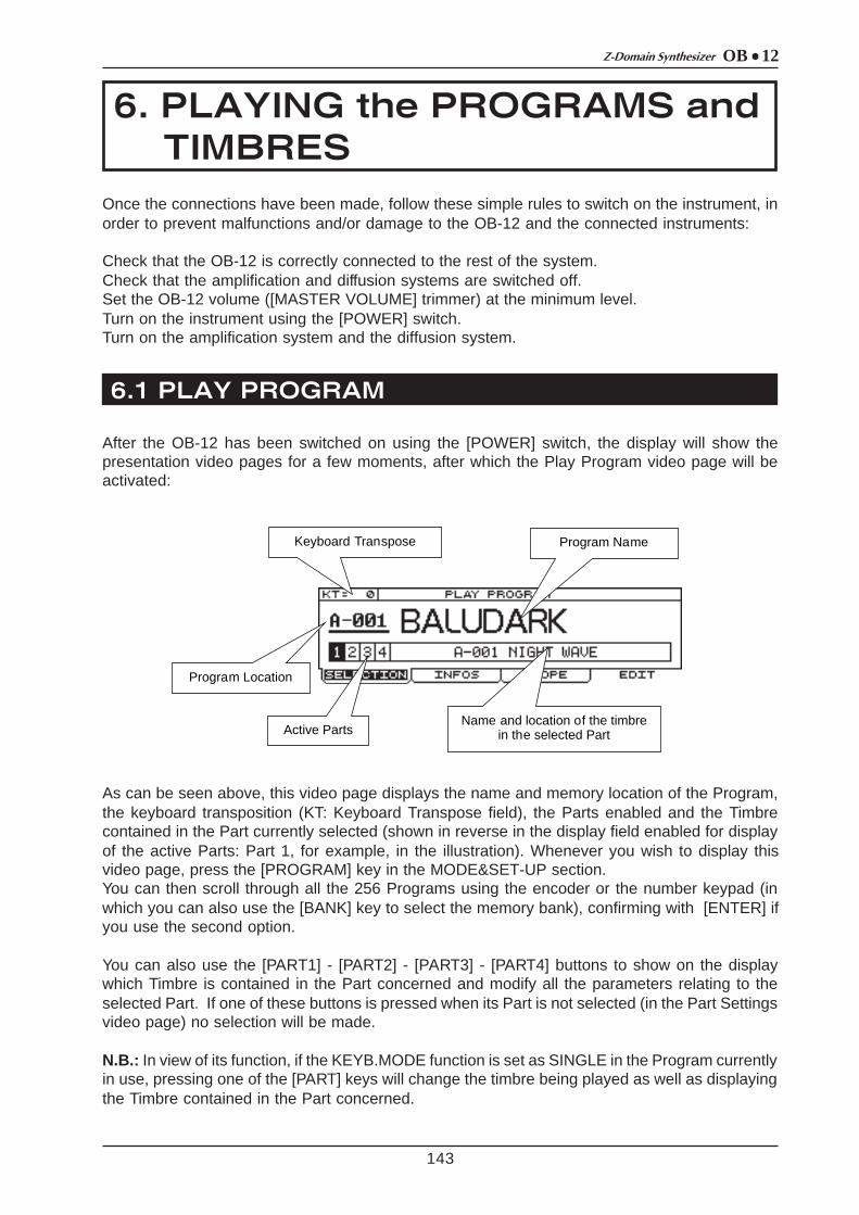
After the OB-12 has been switched on using the [POWER] switch, the display will show thepresentation video pages for a few moments, after which the Play Program video page will beactivated:
Program Name
Program Location
Active Parts
Name and location of the timbre in the selected Part
As can be seen above, this video page displays the name and memory location of the Program,the keyboard transposition (KT: Keyboard Transpose field), the Parts enabled and the Timbrecontained in the Part currently selected (shown in reverse in the display field enabled for displayof the active Parts: Part 1, for example, in the illustration). Whenever you wish to display thisvideo page, press the [PROGRAM] key in the MODE&SET-UP section.You can then scroll through all the 256 Programs using the encoder or the number keypad (inwhich you can also use the [BANK] key to select the memory bank), confirming with [ENTER] ifyou use the second option.
You can also use the [PART1] - [PART2] - [PART3] - [PART4] buttons to show on the displaywhich Timbre is contained in the Part concerned and modify all the parameters relating to theselected Part. If one of these buttons is pressed when its Part is not selected (in the Part Settingsvideo page) no selection will be made.
N.B.: In view of its function, if the KEYB.MODE function is set as SINGLE in the Program currentlyin use, pressing one of the [PART] keys will change the timbre being played as well as displayingthe Timbre contained in the Part concerned.

OB 12 Z-Domain Synthesizer
144
As the above illustration shows, the video page contains three folders called SELECTION, INFOSand SCOPE, plus an EDIT field displaying a function. The folder currently selected is SELECTION,since it is open and its contents are shown in reverse. The function buttons beneath the displaycan be used to select the folder or function in line with the button concerned. Therefore, in thisvideo page you can select SELECTION with button [F1], INFOS with button [F2], SCOPE with[F3] and EDIT with [F4].Use the [CURSOR] keys to select the options in the video pages, and modify them with theencoder or the number keypad. In video pages which do not contain any parameters whosevalues can be modified (such as the Edit Program Menu video page), you can use the encoder(as well as the [CURSOR] keys) to select the options displayed.Another rule to be noted is that while the folders display the current page and additional pages ofthe same menu, the options not contained in a folder correspond to operations. For example,EDIT means editing, CLEAR delete, GO! proceed, etc...
These rules apply to all video pages shown on the display. Refer to them for all the videopages described in the manual.
Now select the INFOS folder; the display will show:
This video page contains the main information about the Program, i.e.:
• P (Part): displays the part for which the information is being displayed and the timbre associatedto the part concerned. The [PART] button can be used to select the part required.
• L (Level): the level of the Timbre contained in the Part concerned.• O (Output): the rear panel outputs associated to the Part.
In addition, the display shows the keyboard range of the Parts in the Program; the line of theselected Part is thicker and the keyboard keys associated to the Part are in reverse.
Now select the SCOPE folder and the display will change to:
You can use the SCOPE parameter, controlled by means of the encoder or the number keypad,to display:
- FILTER: the envelope of the filters in the Timbre currently active.- AMPLIFIER: the envelope of the amplifier present in the Timbre currently active.- FIlTER+AMPLIFIER : the overlapped envelopes of the filters and the amplifier.- OSCILLATOR1 : the sum of the waveforms generated by the first oscillator present in the
Timbre contained in the Part currently active.- OSCILLATOR2 : the sum of the waveforms generated by the second oscillator present in the
Timbre contained in the Part currently active.

OB 12Z-Domain Synthesizer
6.2 PLAY TIMBRE
145
As well as playing an entire Program, the OB-12 also allows the user to play the Timbres individually.From any video page, press the [TIMBRE] button in the MODE&SET-UP section of the centralpanel; the system will leave the Program environment and enable the Timbre present in the Partcurrently selected. As you will see in the KEYBOARD MODE & PART SELECT section of thecentral panel, the keyboard mode will be set as SINGLE (the LED of the [SINGLE] key illuminates)since the selected timbre will be present throughout the keyboard range. The display will thenshow the Play Timbre video page:
As well as the name of the Timbre and the location in which it is memorised, the display alsoshows its volume. After locating the cursor on this field, the encoder or number keypad can beused using the usual procedures to enter the desired value.You can use the [PART] buttons to recall and edit the Timbres contained in the selected part.As for the Play Program video page, this page also consists of three folders called SELECTION,INFOS and SCOPE, plus the EDIT function field.Now select the INFOS folder; the display will show:
This video page shows the status of the main system controllers with the following fields:
• VEL.STATUS (Velocity Status): informs the user whether or not the keyboard velocity control isactive.
• VEL.TYPE (Velocity Type): displays the type of velocity selected.• P.B.STATUS (Pitch Bender Status): informs the user whether the [PITCH] wheel is active.• P.B.COURSE (Pitch Bender Course): displays the range of values controlled by means of the
[PITCH] wheel.• AFTER.STATUS (Aftertouch Status): displays whether the Aftertouch is active.• MODUL.STATUS (Modulation Status): informs the user whether the [MODULATION] wheel is
active.• KEYB.MODE (Keyboard Mode): displays the mode of use of the keyboard.• RIB.1TO (Ribbon 1 To): displays the first parameter controlled by the Ribbon Controller.• RIB.2TO (Ribbon 2 To): displays the second parameter controlled by the Ribbon Controller.
The video page recalled using the SCOPE folder is identical to the video page of the same namein the PROGRAM operating environment, the meaning of which has already been explained inpoint 6.1; refer to this for the information required.
Timbre Location
Timbre Volume
Timbre Name
OB 12 Z-Domain Synthesizer
7. USING the PANEL
7.1 SETTING the FIRST WAVEFORM (OSC.1)
146
Using the panel, allowing real time modifications, is one of the main features of the bestsynthesizers. For this reason, we will first describe all the functions which can be recalled usingthe controls on the front panel.Points 7.1 to 7.7 illustrate the sections used to edit the Timbre to create the desired sound. Points7.8 to 7.15 describe the sections relating to additional functions, such as added effects, equalization,using the wheels and the Ribbon Controller, etc., which are also placed on the front panel sincethey are just as important as the functions described in the previous points.
As we have already seen in our illustration of the OB-12 main structure, the oscillator supplies thebasic waveform for creation of the sound desired.The OB-12 oscillators (Oscillator 1 and Oscillator 2) are able to generate a sound using threemain waveforms, which are:
• a sawtooth waveform (or ramp).• a triangular waveform;• a square waveform (or pulse);
using the panel controls on the display, you can mix (or delete) the three waveforms to allow youto obtain the solution you require.
We will now take a look at the controls on the panel.
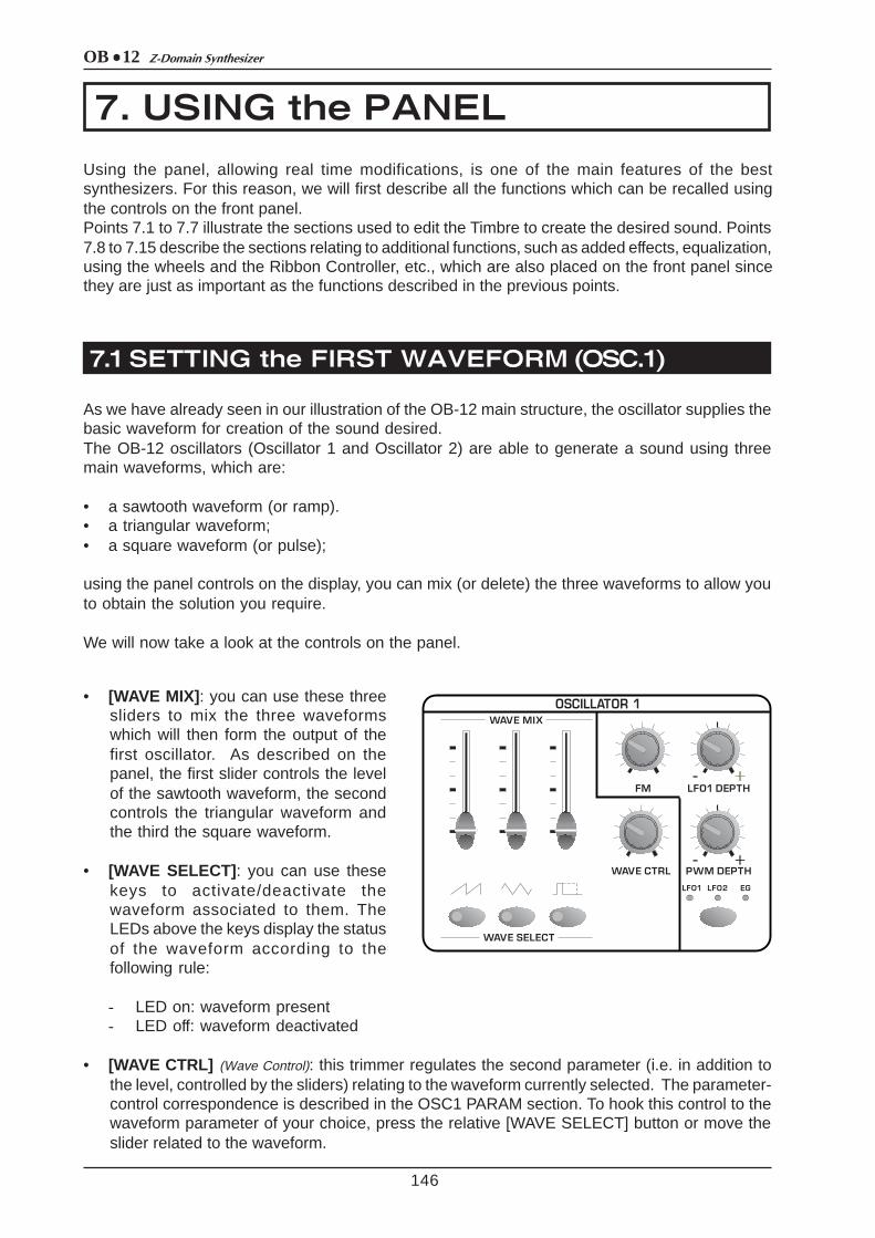
• [WAVE MIX] : you can use these threesliders to mix the three waveformswhich will then form the output of thefirst oscillator. As described on thepanel, the first slider controls the levelof the sawtooth waveform, the secondcontrols the triangular waveform andthe third the square waveform.
• [WAVE SELECT] : you can use thesekeys to activate/deactivate thewaveform associated to them. TheLEDs above the keys display the statusof the waveform according to thefollowing rule:
- LED on: waveform present- LED off: waveform deactivated
• [WAVE CTRL] (Wave Control): this trimmer regulates the second parameter (i.e. in addition tothe level, controlled by the sliders) relating to the waveform currently selected. The parameter-control correspondence is described in the OSC1 PARAM section. To hook this control to thewaveform parameter of your choice, press the relative [WAVE SELECT] button or move theslider related to the waveform.

OB 12Z-Domain Synthesizer
147
The parameters is:
- Sawtooth wave: modification of the SPREAD parameter- Triangular wave: modification of the WRAP parameter- Square wave: modification of the WIDTH parameter
these parameters assume the following functions:
SPREAD: Defines the degree of deformation of the sawtooth waveform. If the parameter isset with values above zero, the sound will be slightly out of tune; this effect will increase asthe value becomes higher.
WRAP : Defines the degree of deformation of the triangular waveform. In this case, the greaterthe deformation, the more overtones are added to the sound generated by the signal.
WIDTH: sets the pulse width of the waveform. The trimmer can be turned to the minimum ormaximum setting to enrich the harmonic spectrum of the sound.
• [FM] (Frequency Modulation): defines the depth of the frequency modulation of the signal generatedby Osc.1 by the signal originating from the second oscillator. As the knob is turned clockwise,the modulation depth increases. The resulting sound will be rich in overtones, suitable formetallic timbres and sound effects.
In addition, you can obtain changes in tone without changing the pitch of Osc.1 by adjustingthe [FINE] and [RANGE] trimmers of the OSCILLATOR 2 section.
If the modulation is not noticeable enough, lower the slider [OSC1ðOSC2] of the OSCILLATORCOMMON section.

OB 12 Z-Domain Synthesizer
7.2 SETTING the SECOND WAVEFORM (OSC.2)
148
• [LFO1 DEPTH] : regulates the depth of the frequency modulation by LFO1 (first low frequencyoscillator) on the pitch (with cyclic variation) of the Osc.1 signal, thus generating vibrato effects.With the knob turned completely to the right, Osc.1 will be affected by the maximum depth ofLFO1 modulation. With the knob in central position, the oscillator will be unaffected by themodulation, and when it is turned completely to the left, the modulation depth will be at themaximum but with opposite phase to that obtained with the knob turned to the right.
• [PWM DEPTH] (Pulse With Modulation Depth): this trimmer can be used to regulate the depth ofmodulation of only the square waveform generated by Osc.1 (and thus not the outcome ofthe three basic waveforms) by the source specified by means of the button below the trimmeritself. This button allows selection of the following as source of the modulating signal:
- LFO1: the first low frequency oscillator- LFO2: the second low frequency oscillator- EG: the envelope generator
The selection will be confirmed by illumination of the corresponding LED.
N.B.: If you have deleted the square waveform (by means of the [WAVE MIX] slider or the[WAVE SELECT] button referred to this signal) you will not be able to hear any acoustic effectgenerated by this control.
As for Oscillator 1, Oscillator 2 also generates the basic waveform of the sound you are creating.Therefore, the two waveforms can be mixed using the BALANCE sliders in the OSC.COMMONsection to obtain the most widely varying sound combinations.Since the functions of these two sections are virtually identical, the panel section is also verymuch the same. As we can see, the controls relating to the second oscillator are:
• [WAVE MIX] : you can usethese three sliders to mixthe three waveforms whichwill then form the output ofthe second oscillator. Asdescribed on the panel, thefirst slider controls the levelof the sawtooth waveform,the second controls thetriangular waveform and thethird the square waveform.

OB 12Z-Domain Synthesizer
149
• [WAVE SELECT] : you can use these keys to activate/deactivate the waveform associated tothem. The LEDs above the keys display the status of the waveform according to the followingrule:
- LED on: waveform present- LED off: waveform deactivated
• [WIDTH]: this trimmer controls the pulse width of the square waveform. The trimmer can beturned to the minimum or maximum setting to enrich the harmonic spectrum of the sound.
• [SYNC] (Synchronisation): this button activates (LED on) and/or deactivates (LED off) thesynchronisation of the waveform leaving Osc.2 with that generated by Osc.1. This meansthat whenever the Osc.1 waveform returns to its starting point the Osc.2 waveform will alsobe reset (or returned to its cycle start). As the diagram below shows, the result is a morecomplex waveform:
If the synchronisation effect is not very noticeable, increase the first slider on the left[OSC1ðOSC2] in the OSCILLATOR COMMON section.
• [LFO1 DEPTH] : regulates the depth of the frequency modulation by the LFO1 (first lowfrequency oscillator) on the pitch (with cyclic variation) of the Osc.2 signal, thus generatingvibrato effects. With the knob turned completely to the right, Osc.2 will be affected by themaximum depth of LFO1 modulation. With the knob in central position, the oscillator will beunaffected by the modulation, and when it is turned completely to the left, the modulationdepth will be at the maximum but with opposite phase to that obtained with the knob turned tothe right.
• [FINE]: regulates the fine tuning of Osc.2 in a range of ± 50 hundredths of a semitone. Whenthe trimmer is in the central position, there is no change in the pitch.
• [RANGE] : regulates the tuning of Osc.2 in a range of ± 24 semitones. When the trimmer is inthe central position, there is no change in the pitch.
The main feature of these two controls is that they put the second oscillator out of tune withthe first. This allows you to generate effects giving space to the sound, and harmonisationbetween the two oscillators (if the difference in pitch is set, for example, at 5-7 semitones).
• [PWM DEPTH] (Pulse With Modulation Depth): this trimmer can be used to regulate the depth ofmodulation of only the square waveform generated by Osc.2 by the source specified bymeans of the button below the trimmer itself. This button allows selection of the following assource of the modulating signal:
- LFO1: the first low frequency oscillator
OB 12 Z-Domain Synthesizer
7.3 MODIFYNG the PARAMETERS COMMON TOOSC.1 and OSC.2 (OSC.COMMON)
150
- LFO2: the second low frequency oscillator- EG: the envelope generator
The selection will be confirmed by illumination of the corresponding LED.
N.B.: If you have deleted the square waveform (by means of the [WAVE MIX] slider or the[WAVE SELECT] button referred to this signal) you will not be able to hear any acoustic effectgenerated by this control.
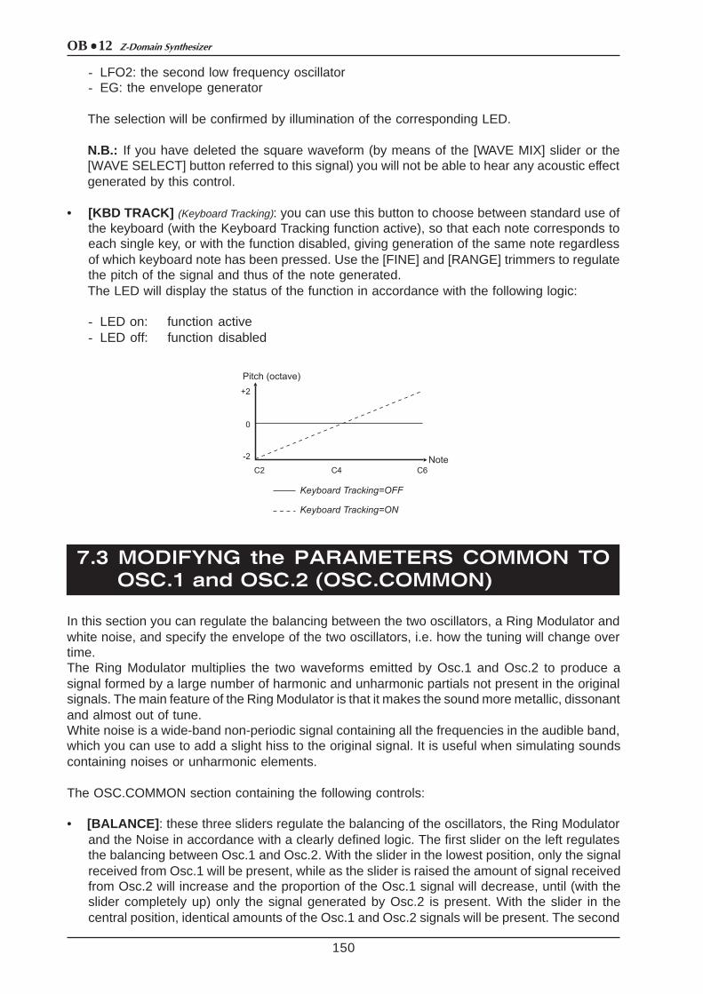
• [KBD TRACK] (Keyboard Tracking): you can use this button to choose between standard use ofthe keyboard (with the Keyboard Tracking function active), so that each note corresponds toeach single key, or with the function disabled, giving generation of the same note regardlessof which keyboard note has been pressed. Use the [FINE] and [RANGE] trimmers to regulatethe pitch of the signal and thus of the note generated.The LED will display the status of the function in accordance with the following logic:
- LED on: function active- LED off: function disabled
In this section you can regulate the balancing between the two oscillators, a Ring Modulator andwhite noise, and specify the envelope of the two oscillators, i.e. how the tuning will change overtime.The Ring Modulator multiplies the two waveforms emitted by Osc.1 and Osc.2 to produce asignal formed by a large number of harmonic and unharmonic partials not present in the originalsignals. The main feature of the Ring Modulator is that it makes the sound more metallic, dissonantand almost out of tune.White noise is a wide-band non-periodic signal containing all the frequencies in the audible band,which you can use to add a slight hiss to the original signal. It is useful when simulating soundscontaining noises or unharmonic elements.
The OSC.COMMON section containing the following controls:
• [BALANCE] : these three sliders regulate the balancing of the oscillators, the Ring Modulatorand the Noise in accordance with a clearly defined logic. The first slider on the left regulatesthe balancing between Osc.1 and Osc.2. With the slider in the lowest position, only the signalreceived from Osc.1 will be present, while as the slider is raised the amount of signal receivedfrom Osc.2 will increase and the proportion of the Osc.1 signal will decrease, until (with theslider completely up) only the signal generated by Osc.2 is present. With the slider in thecentral position, identical amounts of the Osc.1 and Osc.2 signals will be present. The second

OB 12Z-Domain Synthesizer
151
slider ([RING MOD]) balancesthe signal received from the firstslider (i.e. Osc.1+Osc.2) withthe Ring Modulator. As theslider is raised the amount ofRing Modulator signalincreases. The third slider([NOISE]) balances the signalreceived from the second slider(i.e. Osc.1+Osc.2+RingModulator) with the white noise.As the slider is raised, theamount of white noiseincreases.
• [ATTACK] (Attack Time): regulates the Attack Time parameter ofthe oscillator envelope, meaning the duration of the initialmodification (attack) in the pitch.
• [DECAY] (Decay Time): regulates the Decay Time parameter ofthe oscillator envelope, meaning the duration of the initialmodification (decay) in the pitch.
• [ENV DEPTH] (Envelope Depth): you can use this trimmerto regulate the depth of the envelope applied to Osc.1and Osc.2. Turning the trimmer clockwise from thecentre increases the modification of the pitch; when itis turned anti-clockwise from the central position themodification will be increased in the opposite direction,while with the trimmer in the central position theenvelope will not affect the pitch.
The envelope is assigned to the oscillators by means of the button under the trimmer[ENV.DEPTH]. The LEDs under the trimmer will display the assignment made in accordancewith the following logic:
- LED [OSC.1] on: envelope assigned to the first oscillator- LED [OSC.2] on: envelope assigned to the second oscillator

OB 12 Z-Domain Synthesizer
7. 4 MODIFYNG the TIMBRE (FILTERS)
152
As we have mentioned when discussing the synthesis technique used by the OB-12, the signalgenerated by the oscillators is rich in harmonics, or in other words it has a very wide frequencycontent. The filter can be used to attenuate specific harmonics, or a given range of frequencies,in order to obtain the desired sound (with regard to the timbre quality).In fact, the OB-12 FILTER section uses two filters which can be set up exactly as required withregard to type, cut-off frequency and their interconnection.
The filter control section is the following:
• [FREQUENCY] : regulates the filter cut-off frequency. Turning the trimmer anti-clockwiseincreases the cut-off frequency. Depending on the type of filter, the significance of the cut-offfrequency varies: refer to the description of the [FILTER 1] button with regard to operation ofthe filters in relation to the cut-off frequency.
• [KBD TRACK] (Keyboard Tracking): you can use thistrimmer to vary the behaviour of the filter in relationto which key is pressed on the keyboard.Intermediate values will keep the trigger frequencythe same throughout the keyboard range. Thismeans that higher notes will have a softer soundthan lower notes, with fewer partials. Turning thetrimmer completely to the right will increase theharmonics in the higher notes, so that they arebrighter while the lower notes are darker. Conversely,if the trimmer is turned completely to the left thehigher notes will have even fewer harmonics thanin the standard setup (trimmer in central position).The lower notes will therefore be brighter, and thehigher notes darker.
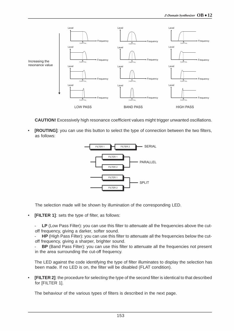
• [RESONANCE] : regulates the resonance coefficient. As the diagram shows, the resonancecauses an enhancement of the frequencies close to the cut-off frequency value. Increasingthe resonance will give greater selectivity in establishing the frequencies affected by theenhancement.
OB 12Z-Domain Synthesizer
153
CAUTION! Excessively high resonance coefficient values might trigger unwanted oscillations.
• [ROUTING] : you can use this button to select the type of connection between the two filters,as follows:
The selection made will be shown by illumination of the corresponding LED.
• [FILTER 1] : sets the type of filter, as follows:
- LP (Low Pass Filter): you can use this filter to attenuate all the frequencies above the cut-off frequency, giving a darker, softer sound.- HP (High Pass Filter): you can use this filter to attenuate all the frequencies below the cut-off frequency, giving a sharper, brighter sound.- BP (Band Pass Filter): you can use this filter to attenuate all the frequencies not presentin the area surrounding the cut-off frequency.
The LED against the code identifying the type of filter illuminates to display the selection hasbeen made. If no LED is on, the filter will be disabled (FLAT condition).
• [FILTER 2] : the procedure for selecting the type of the second filter is identical to that describedfor [FILTER 1].
The behaviour of the various types of filters is described in the next page.
OB 12 Z-Domain Synthesizer
154
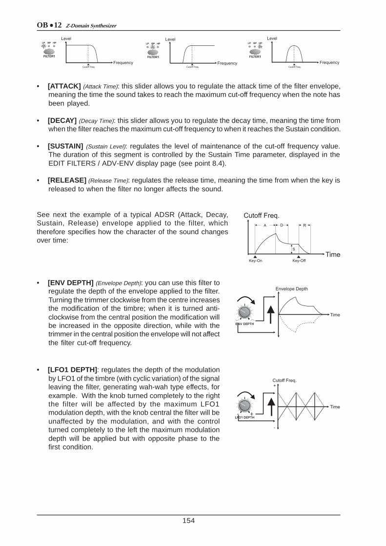
• [ATTACK] (Attack Time): this slider allows you to regulate the attack time of the filter envelope,meaning the time the sound takes to reach the maximum cut-off frequency when the note hasbeen played.
• [DECAY] (Decay Time): this slider allows you to regulate the decay time, meaning the time fromwhen the filter reaches the maximum cut-off frequency to when it reaches the Sustain condition.
• [SUSTAIN] (Sustain Level): regulates the level of maintenance of the cut-off frequency value.The duration of this segment is controlled by the Sustain Time parameter, displayed in theEDIT FILTERS / ADV-ENV display page (see point 8.4).
• [RELEASE] (Release Time): regulates the release time, meaning the time from when the key isreleased to when the filter no longer affects the sound.
See next the example of a typical ADSR (Attack, Decay,Sustain, Release) envelope applied to the filter, whichtherefore specifies how the character of the sound changesover time:
• [ENV DEPTH] (Envelope Depth): you can use this filter toregulate the depth of the envelope applied to the filter.Turning the trimmer clockwise from the centre increasesthe modification of the timbre; when it is turned anti-clockwise from the central position the modification willbe increased in the opposite direction, while with thetrimmer in the central position the envelope will not affectthe filter cut-off frequency.
• [LFO1 DEPTH] : regulates the depth of the modulationby LFO1 of the timbre (with cyclic variation) of the signalleaving the filter, generating wah-wah type effects, forexample. With the knob turned completely to the rightthe filter will be affected by the maximum LFO1modulation depth, with the knob central the filter will beunaffected by the modulation, and with the controlturned completely to the left the maximum modulationdepth will be applied but with opposite phase to thefirst condition.

OB 12Z-Domain Synthesizer
7. 5 VOLUME CONTROL (AMPLIFIER)
155
The amplifier controls the volume of the sound, varying it in relation to time when required. Thissection allows you to set the envelope which will control the amplifier and the distribution of thesound within the stereophonic panorama.
The Amplifier section is as follows:
• [ATTACK] (Attack Time): this slider allows youto regulate the attack time of the amplifierenvelope, meaning the time the sound takesto reach the maximum signal level once thenote has been played.
• [DECAY] (Decay Time): this slider allows you toregulate the decay time, meaning the timefrom when the signal reaches the maximumlevel to when it reaches the Sustain condition.
• [SUSTAIN] (Sustain Level): regulates the levelof maintenance of the signal. The duration ofthis segment is controlled by the Sustain Timeparameter, displayed in the EDIT FILTERS /ADV-ENV display page (see point 8.5).
• [RELEASE] (Release Time): regulates the release time, meaning the time from when the key isreleased to when the sound is no longer present.
See next the example of a typical ADSR (Attack, Decay,Sustain, Release) envelope applied to the amplifier, whichtherefore specifies how the level of the sound changes overtime:
• [AMOUNT] : regulates the volume of the Timbre. Clockwise rotation provides higher soundvolumes. This control therefore allows you to set different volumes for the various Timbreswhich make up a Program (the general volume of which can be controlled using the [MASTERVOLUME] trimmer).
• [LFO1 DEPTH] : this trimmer provides two specificfunctions. When the LED of the [AUTOPAN] button ison, the trimmer regulates the amount of signal whichwill be affected by the Pan function. In the centralposition, the sound will not move within the stereophonicpanorama. In either of the extreme positions, the soundwill be completely affected by the Pan effect and inopposite directions (depending the chosen end of thetrimmer scale).

OB 12 Z-Domain Synthesizer
7. 6 MODULATING the SOUND CYCLICALLY (LFO1)
156
When the [AUTOPAN] LED is off, the trimmer regulatesthe depth of modulation by LFO1 on the sound volume,thus generating tremolo effects.
• [AUTOPAN] : this button establishes whether LFO1 is to be assigned to the Pan (i.e. cyclicshift of the signal from right to left); in this case the LED will illuminate. If the LED is off, theAutopan function will not be available and LFO1 will modulate the signal level in cyclic mode.
N.B.: If you are using mono outputs (MAIN OUT [L/MONO], or AUX [1] or AUX [2] on its own)the Pan effect will not be audible.
As we have already seen, LFO1 (Low Frequency Oscillator) generates a waveform which, whenrequired, will modulate the signal present in the sections we have described so far. This allowsyou to vary the pitch of the sound (in the Osc.1 and 2 sections), the timbre (in the Filters), and thevolume/Pan (in the Amplifier), all in cyclic mode.
We will now take a detailed look at this section:
• [RATE] : regulates the frequency of the modulating signal. Turnthe knob clockwise to increase the frequency of the signal andthus the modulation rate.
• [FADE] : sets the time in which the level of the modulating signalwill reach the maximum modulation value specified with the [LFO1DEPTH] trimmers in the various generation sections. Turn thetrimmer clockwise to increase this delay.

OB 12Z-Domain Synthesizer
(sawtooth or ramp): the signal passesimmediately from a maximum to aminimum value.
(triangular): starting from a minimumlevel, the signal rises to a maximumvalue in a given period of time, thenreturns to the minimum level in thesame period of time.
(square): the signal assumes twosingle values.
(random): the signal assumes randomvalues.
7.7 MODULATING the SOUND with the[MODULATION] WHEEL (LFO2)
157
LFO2 works in exactly the same way as LFO1, with the sole difference that the amount ofmodulation can be adjusted using the [MODULATION] wheel.
The panel section comprises:
• [RATE] : regulates the frequency of the modulating signal. Turnthe trimmer clockwise to increase the frequency of the signal.
• [DEPTH] : regulates the maximum modulation depth; this is thenregulated by the [MODULATION] wheel, which sends it to thevarious sections.
• [WAVE SELECT] : specifies the waveform of the modulatingsignal. The waveforms are the same as those generated by LFO1.
• [DEPTH SELECT] : this button allows you to specify the sectionon which you are regulating the maximum LFO2 modulation depthby means of the [DEPTH] trimmer.
OB 12 Z-Domain Synthesizer
7. 8 SETTING the KEYBOARD (KEYBOARD)
158
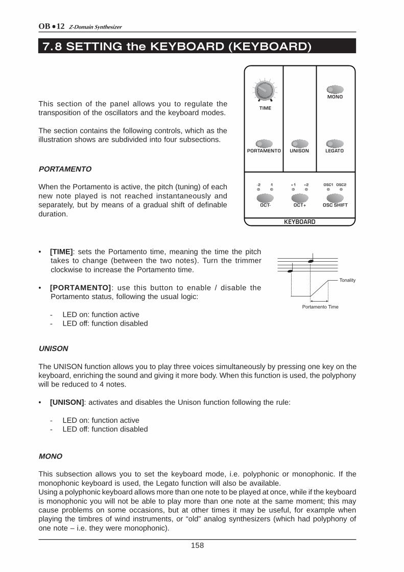
This section of the panel allows you to regulate thetransposition of the oscillators and the keyboard modes.
The section contains the following controls, which as theillustration shows are subdivided into four subsections.
PORTAMENTO
When the Portamento is active, the pitch (tuning) of eachnew note played is not reached instantaneously andseparately, but by means of a gradual shift of definableduration.
• [TIME] : sets the Portamento time, meaning the time the pitchtakes to change (between the two notes). Turn the trimmerclockwise to increase the Portamento time.
• [PORTAMENTO] : use this button to enable / disable thePortamento status, following the usual logic:
- LED on: function active- LED off: function disabled
UNISON
The UNISON function allows you to play three voices simultaneously by pressing one key on thekeyboard, enriching the sound and giving it more body. When this function is used, the polyphonywill be reduced to 4 notes.
• [UNISON] : activates and disables the Unison function following the rule:
- LED on: function active- LED off: function disabled
MONO
This subsection allows you to set the keyboard mode, i.e. polyphonic or monophonic. If themonophonic keyboard is used, the Legato function will also be available.Using a polyphonic keyboard allows more than one note to be played at once, while if the keyboardis monophonic you will not be able to play more than one note at the same moment; this maycause problems on some occasions, but at other times it may be useful, for example whenplaying the timbres of wind instruments, or “old” analog synthesizers (which had polyphony ofone note – i.e. they were monophonic).
OB 12Z-Domain Synthesizer
159
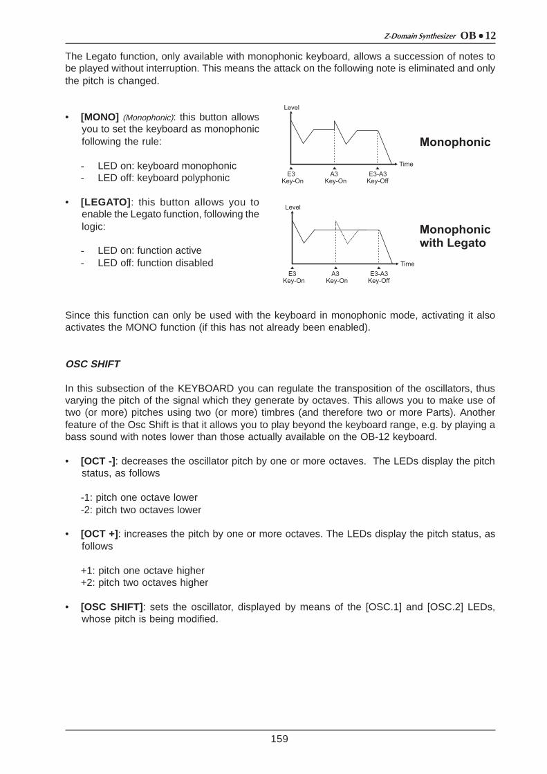
The Legato function, only available with monophonic keyboard, allows a succession of notes tobe played without interruption. This means the attack on the following note is eliminated and onlythe pitch is changed.
• [MONO] (Monophonic): this button allowsyou to set the keyboard as monophonicfollowing the rule:
- LED on: keyboard monophonic- LED off: keyboard polyphonic
• [LEGATO] : this button allows you toenable the Legato function, following thelogic:
- LED on: function active- LED off: function disabled
Since this function can only be used with the keyboard in monophonic mode, activating it alsoactivates the MONO function (if this has not already been enabled).
OSC SHIFT
In this subsection of the KEYBOARD you can regulate the transposition of the oscillators, thusvarying the pitch of the signal which they generate by octaves. This allows you to make use oftwo (or more) pitches using two (or more) timbres (and therefore two or more Parts). Anotherfeature of the Osc Shift is that it allows you to play beyond the keyboard range, e.g. by playing abass sound with notes lower than those actually available on the OB-12 keyboard.
• [OCT -] : decreases the oscillator pitch by one or more octaves. The LEDs display the pitchstatus, as follows
-1: pitch one octave lower-2: pitch two octaves lower
• [OCT +] : increases the pitch by one or more octaves. The LEDs display the pitch status, asfollows
+1: pitch one octave higher+2: pitch two octaves higher
• [OSC SHIFT] : sets the oscillator, displayed by means of the [OSC.1] and [OSC.2] LEDs,whose pitch is being modified.

OB 12 Z-Domain Synthesizer
7. 9 ADDING EFFECTS to the SOUND (EFFECTS)
160
The OB-12 offers an effects section with whichyou can add four fully configurable algorithmsto your sound.
The OB-12 allows you to make use of thefollowing algorithms:
- OVERDRIVE: simulates an amplifierbrought to saturation. Can be used whencreating timbres which simulate a guitar.
- CHORUS: adds space and depth to thesound.
- DELAY : produces delayed copies of thesignal, such as the echo effect.
- REVERB: simulates the diffusion of thesound in enclosed environments, bearing inmind the reflection and absorption of thewalls.
the controls on the panel are:
• [OVERDRIVE] : adds / bypasses the Overdrive effect.
• [CHORUS] : adds / bypasses the Chorus effect.
• [DELAY] : adds / bypasses the Delay effect.
• [REVERB] : adds / bypasses the Reverb effect.
For all the buttons, the same logic applies:
- LED on: effect active- LED off: effect disabled
• [LEVEL/PARAMETER] : this button allows you to set whether the four trimmers associated tothe four effects are to be used to regulate the level of each algorithm (LED off) or a parameterdefined in the EFFECTS SETTINGS video pages.
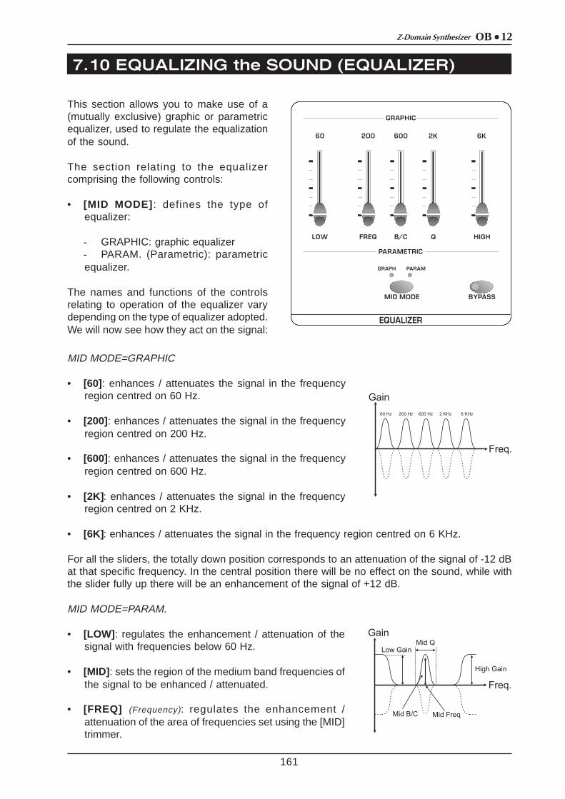
OB 12Z-Domain Synthesizer
7. 10 EQUALIZING the SOUND (EQUALIZER)
161
This section allows you to make use of a(mutually exclusive) graphic or parametricequalizer, used to regulate the equalizationof the sound.
The section relating to the equalizercomprising the following controls:
• [MID MODE] : defines the type ofequalizer:
- GRAPHIC: graphic equalizer- PARAM. (Parametric): parametricequalizer.
The names and functions of the controlsrelating to operation of the equalizer varydepending on the type of equalizer adopted.We will now see how they act on the signal:
MID MODE=GRAPHIC
• [60] : enhances / attenuates the signal in the frequencyregion centred on 60 Hz.
• [200] : enhances / attenuates the signal in the frequencyregion centred on 200 Hz.
• [600] : enhances / attenuates the signal in the frequencyregion centred on 600 Hz.
• [2K] : enhances / attenuates the signal in the frequencyregion centred on 2 KHz.
• [6K] : enhances / attenuates the signal in the frequency region centred on 6 KHz.
For all the sliders, the totally down position corresponds to an attenuation of the signal of -12 dBat that specific frequency. In the central position there will be no effect on the sound, while withthe slider fully up there will be an enhancement of the signal of +12 dB.
MID MODE=PARAM.
• [LOW] : regulates the enhancement / attenuation of thesignal with frequencies below 60 Hz.
• [MID] : sets the region of the medium band frequencies ofthe signal to be enhanced / attenuated.
• [FREQ] (Frequency): regulates the enhancement /attenuation of the area of frequencies set using the [MID]trimmer.

OB 12 Z-Domain Synthesizer
7. 11 REGULATING the GENERAL VOLUME (VOLUME)
7. 12 USING the [PITCH] and [MODULATION] WHEELS
162
• [Q]: sets the band-width of operation on the frequency set with the [MID] trimmer.
• [HIGH]: regulates the enhancement / attenuation of the signal with frequencies higher than 6KHz.
The trimmers which regulate the amount of action on the signal ([LOW], [FREQ] and [HIGH])operate exactly as described for the graphic equalizer. For the [MID] and [Q] trimmers, higherslider positions set higher values of the parameters they control.
• [BYPASS] : sets whether the Equalizer section is to be bypassed (LED on) or not (LED off).
This section allows you to regulate the volume of the Program, and therefore not of the individualtimbre.
• [MASTER VOLUME] : you can use this slider to regulate the final volume of the Program.
There are two wheels beside the OB-12 keyboard allowing the user to:
• [PITCH]: control the general pitch of the instrument, with consequent sending of MIDI PitchBend messages.
• [MODULATION] : control the depth of modulation by the LFO2 on the sections specified in thesection of the same name; control the Manual Morphing effect; control the parameters associatedto the Aftertouch.
As well as the two wheels, the WHEEL MODE section also contains the controls enabled forassignment of functions to the [MODULATION] wheel.
This section therefore contains the following controls:
• [STND-M.MORPH] (Standard-Manual Morph): enables the twomodes for use of the [MODULATION] wheel, i.e. for modulatingthe signals by means of LFO2 ([STND] LED on) or forcontrolling the Manual Morph function ([M.MORPH] LED on).Refer to point 9.9 for further information concerning use ofthe [MODULATION] wheel for controlling the Manual Morph.N.B.: control of the Manual Morph can only be assigned to the [MODULATION] wheel if thisfunction is active.
• [AFTERTOUCH EXCHANGE] : with this function active (button LED on), the parameterscontrolled with the Aftertouch can only be controlled by means of the [MODULATION] wheel,while the depth of modulation by LFO2 (the LFO2 DEPTH parameter) will be controlled by theAftertouch.N.B. : control of the Manual Morph is independent of the setting of this function. You cantherefore control this function by means of the [MODULATION] wheel in both cases.

OB 12Z-Domain Synthesizer
7. 13 ENABLING the VELOCITY and AFTERTOUCH
7. 14 USING the RIBBON CONTROLLER
163
The KEYBOARD SENSE section contains the controls for enabling and disabling the Velocityand/or the Aftertouch. You can use the Velocity, meaning the dynamic applied to the keyboardkeys, to control up to 19 sound generation parameters (see point 8.9), while the Aftertouch,meaning the force applied to the key after it has been depressed, can be used to regulate up to14 generation parameters (see point 8.9).
The relative front panel section is as follows:
• VELOCITY: enables (LED illuminates) or disables (LED off)use of the note velocity to control generation parameters,which can be assigned using the CONTROLLERS section ofthe EDIT TIMBRE display menu (point 8.9).
• AFTERTOUCH: enables (LED illuminates) or disables (LED off) use of the Aftertouch tocontrol generation parameters, which can be assigned using the CONTROLLERS section ofthe EDIT TIMBRE display menu (point 8.9).
The Ribbon Controller allows the user to modify two generation parameters simultaneously bysimply placing a finger on and/or moving it over its surface. This allows you to modify the tone asif you were using the knobs on the front panel.
The OB-12 Ribbon Controller is illustrated below:
To assign the parameters you wish to control using this device, use the EDIT CONTROLLERSdisplay menu (point 8.9).As you can see, as well as the Ribbon Controller there are also two buttons close to it, as follows:
• [RELATIVE] : when this function is active, the Ribbon Controller “neutral” position (the positionwhich does not produce any variation of the sound, or the central position for controls withpositive and negative values and the far left position for controls with positive values only) isassumed on the basis of where the control surface is first touched.
• [HOLD] : when this function is selected, each variation of the parameter (or parameters)assigned to the Ribbon Controller will be maintained even after the finger is removed from thecontrol surface.

OB 12 Z-Domain Synthesizer
8. EDIT TIMBRE
164
The Edit Timbre function allows the user to set all the parameters relating to the chain for generationof a given sound. Section 7 “Using the panel” has already illustrated the functions of all thecontrols needed to create the main parameters of a sound. The display pages allow you to defineadditional settings for total control of the editing of a timbre. This section explains all these settings.However, anyone who has decided to skip section 7 is advised to read that section of the manualbefore proceeding with this section.
For the procedures for selection of the menus and parameters, refer to point 6.1 – “Play Program”.
From any video page, press the [TIMBRE] button in the MODE&SET-UP section of the frontpanel. You have now selected the TIMBRE operating environment and the display will show:
The video pages which can be recalled by selecting the INFOS and SCOPE folders have alreadybeen described in point 6.2.We will now examine all the procedures for modifying the sound generated by the OB-12.Select the EDIT function; the display will change to:
This video page shows the menu for editing a Timbre. It consists of the following sections:
1-LFO1: regulation of the parameters relating to the first low frequency oscillator.2-OSC.COMMON: regulation of the common parameters of Osc.1 and Osc.2.3-OSCILLATOR 1 : setting of the parameters for control of oscillator 1.4-OSCILLATOR 2 : setting of the parameters for control of oscillator 25-FILTERS: regulation of the parameters relating to the two filters.6-AMPLIFIER : regulation of the amplifier setting parameters.7-LFO2: setting of the controls of the second low frequency oscillator.8-MODE: setting of the keyboard modes, unison and oscillator transposition.9-CONTROLLERS : setting of the Velocity, Aftertouch, Ribbon Controller and [PITCH] and[MODULATION] wheels.
As you will see, when modifications are made to the parameters of the various sections, eachchange is shown on the display, not only numerically but also in graphic form, to give a fullunderstanding of what is being adjusted.
To make the various sound generation sections clearer, the points which follow will not appear inthe same sequence as on the panel and on the display from the EDIT TIMBRE MENU videopage; instead, reference will be to their position within the generation chain (and therefore as

OB 12Z-Domain Synthesizer
8.1 EDIT OSCILLATOR 1
165
they have been described in section 7).Alongside the name (or code) of the parameter whose function is being discussed, in roundbrackets you will find the full name of the parameter and of the panel control found in the sectionwhose contents are being explained, used to modify the parameter in question. If the descriptionof the panel control is accompanied by reference to the section in which it is found, this meansthat the control in question also appears in other sections of the front panel.
In real musical instruments, there is always a mechanism which transforms a mechanical action(pressing a keyboard key, for example) or a fluid dynamic effect (blowing into a wind instrument,for example) into an energy wave (the sound wave). This energy, or the sound wave, is the basisfor creating a sound.In synthesizers, the basic waveform is generated by the oscillators.
Oscillators may be analog (VCO: Voltage Controlled Oscillator) or digital (DCO: Digitally ControlledOscillator, as in the case of the OB-12).
Oscillators normally generate three fundamental waveforms:
• a sawtooth waveform (or ramp).• a triangular waveform;• a square waveform (or pulse);
Using a DCO it is easy to obtain a waveform, but the nature of the resulting sound is flat anduninteresting. The waveform has an accuracy and constancy not found in the natural soundsmankind is used to, including the sounds of acoustic instruments.What’s more, if the aim is to create less real sounds, using simple waveforms does not guaranteethe generation of complex unnatural sounds.
In order to solve this problem, the OB-12 uses two oscillators (the first of them will be describedhere) capable of generating three main totally configurable waveforms (as we have seen, theyare a sawtooth wave, a triangular wave and a square wave) which are then added together tocreate a “sum” of the three initial waveforms.
The diagram in the next page will help you to understand this “combination” of waveforms:
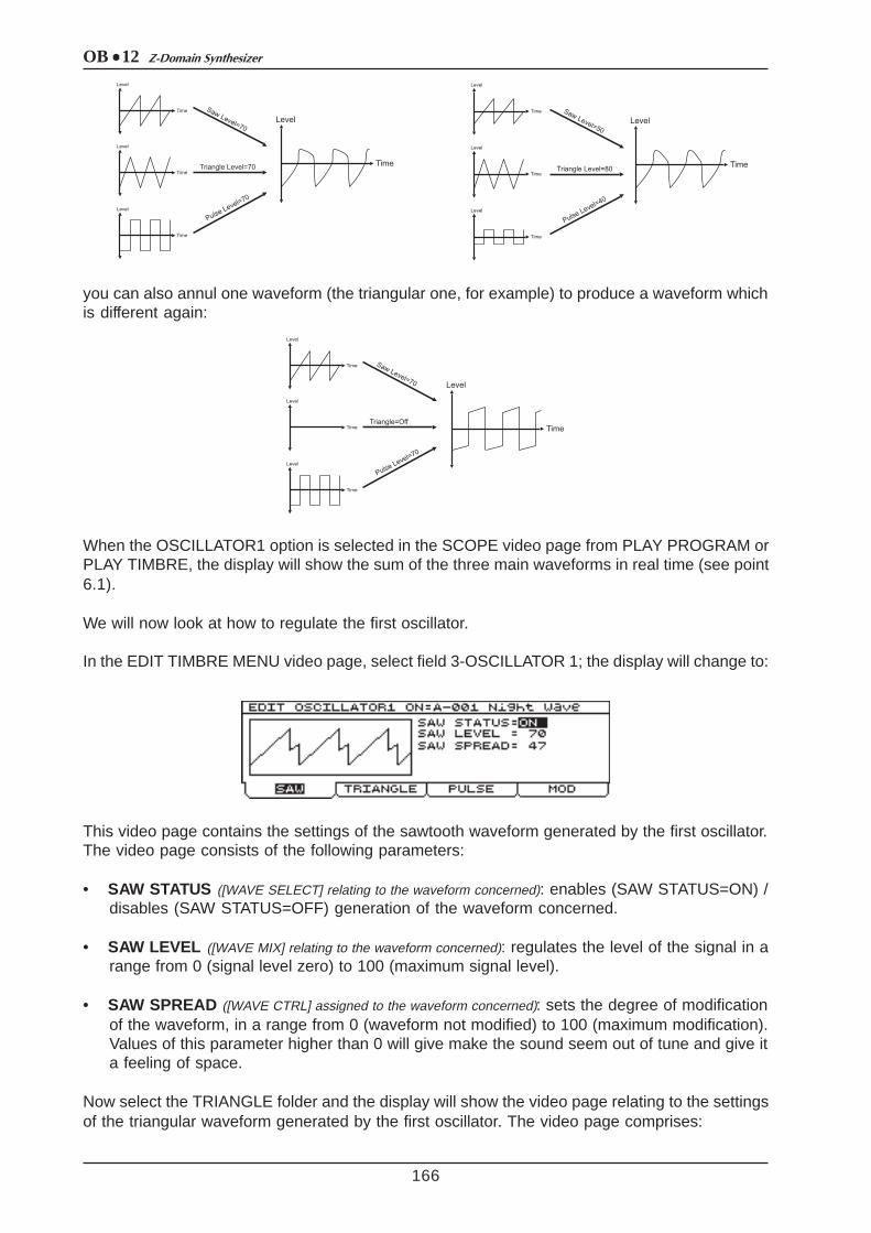
OB 12 Z-Domain Synthesizer
166
you can also annul one waveform (the triangular one, for example) to produce a waveform whichis different again:
When the OSCILLATOR1 option is selected in the SCOPE video page from PLAY PROGRAM orPLAY TIMBRE, the display will show the sum of the three main waveforms in real time (see point6.1).
We will now look at how to regulate the first oscillator.
In the EDIT TIMBRE MENU video page, select field 3-OSCILLATOR 1; the display will change to:
This video page contains the settings of the sawtooth waveform generated by the first oscillator.The video page consists of the following parameters:
• SAW STATUS ([WAVE SELECT] relating to the waveform concerned): enables (SAW STATUS=ON) /disables (SAW STATUS=OFF) generation of the waveform concerned.
• SAW LEVEL ([WAVE MIX] relating to the waveform concerned): regulates the level of the signal in arange from 0 (signal level zero) to 100 (maximum signal level).
• SAW SPREAD ([WAVE CTRL] assigned to the waveform concerned): sets the degree of modificationof the waveform, in a range from 0 (waveform not modified) to 100 (maximum modification).Values of this parameter higher than 0 will give make the sound seem out of tune and give ita feeling of space.
Now select the TRIANGLE folder and the display will show the video page relating to the settingsof the triangular waveform generated by the first oscillator. The video page comprises:

OB 12Z-Domain Synthesizer
167
• TRIANGLE STATUS ([WAVE SELECT] relating to the waveform concerned): activates (TRIANGLESTATUS=ON) / deactivates (TRIANGLE STATUS=OFF) the triangular waveform.
• TRIANGLE LEVEL ([WAVE MIX] relating to the triangular waveform): regulates the level of the signalin a range from 0 (signal level zero) to 100 (maximum signal level).
• TRIANGLE WRAP ([WAVE CTRL] assigned to this waveform): sets the degree of deformation of thewaveform in a range from 0 (waveform not modified) to 100 (maximum deformation). Usingthis parameter will allow you to add a large number of overtones to the fundamental.
If you now select the PULSE folder, you will select the page for programming the square (pulse)waveform generated by the first oscillator. The video page displayed is as follows:
comprising the following parameters:
• PULSE STATUS ([WAVE SELECT] relating to the square waveform): activates (PULSE STATUS=ON)/ deactivates (PULSE STATUS=OFF) the waveform concerned.
• PULSE LEVEL ([WAVE MIX] associated to the square waveform): regulates the level of the squarewaveform in a range between 0 (signal level zero) and 100 (maximum signal level).
• PULSE WIDTH ([WAVE CTRL] assigned to the waveform concerned): regulates the pulse width in arange between 0 (minimum pulse width) and 100 (maximum pulse width). Setting this parameterwith minimum or maximum values allows you to enrich the harmonic spectrum of the sound.
If you now select the MOD folder you will display the parameters relating to the signals which willmodulate Osc.1. The video page comprises:
containing the following options:
• OSC 2 FREQUENCY MODULATION ([FM]): sets the depth of modulation of the frequency ofthe signal generated by Osc.1 by the signal originating from the second oscillator.
• LFO1 MOD.DEPTH (LFO1 Modulation Depth, [LFO1 DEPTH] of the OSCILLATOR 1 section): regulatesthe depth of the frequency modulation of the signal originating from LFO1 on the signalleaving the first oscillator. The range of values is –50 (maximum frequency modulation with
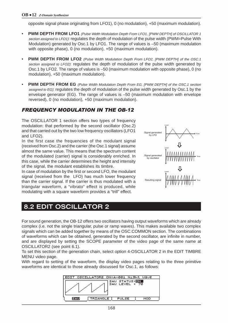
OB 12 Z-Domain Synthesizer
8.2 EDIT OSCILLATOR 2
168
opposite signal phase originating from LFO1), 0 (no modulation), +50 (maximum modulation).
• PWM DEPTH FROM LFO1 (Pulse Width Modulation Depth From LFO1, [PWM DEPTH] of OSCILLATOR 1section assigned to LFO1): regulates the depth of modulation of the pulse width (PWM=Pulse WithModulation) generated by Osc.1 by LFO1. The range of values is –50 (maximum modulationwith opposite phase), 0 (no modulation), +50 (maximum modulation).
• PWM DEPTH FROM LFO2 (Pulse Width Modulation Depth From LFO2, [PWM DEPTH] of the OSC.1section assigned to LFO2): regulates the depth of modulation of the pulse width generated byOsc.1 by LFO2. The range of values is –50 (maximum modulation with opposite phase), 0 (nomodulation), +50 (maximum modulation).
• PWM DEPTH FROM EG (Pulse Width Modulation Depth From EG, [PWM DEPTH] of the OSC.1 sectionassigned to EG): regulates the depth of modulation of the pulse width generated by Osc.1 by theenvelope generator (EG). The range of values is –50 (maximum modulation with envelopereversed), 0 (no modulation), +50 (maximum modulation).
FREQUENCY MODULATION IN THE OB-12
The OSCILLATOR 1 section offers two types of frequencymodulation: that performed by the second oscillator (Osc.2)and that carried out by the two low frequency oscillators (LFO1and LFO2).In the first case the frequencies of the modulant signal(received from Osc.2) and the carrier (the Osc.1 signal) assumealmost the same value. This means that the spectrum contentof the modulated (carrier) signal is considerably enriched. Inthis case, while the carrier determines the height and intensityof the signal, the modulant establishes its timbre.In case of modulation by the first or second LFO, the modulantsignal (received from the LFO) has much lower frequencythan the carrier signal. If the carrier is thus modulated with atriangular waveform, a “vibrato” effect is produced, whilemodulating with a square waveform provides a “trill” effect.
For sound generation, the OB-12 offers two oscillators having output waveforms which are alreadycomplex (i.e. not the single triangular, pulse or ramp waves). This makes available two complexsignals which can be added together by means of the OSC.COMMON section. The combinationsof waveforms which can be obtained, generated by the second oscillator, are infinite in number,and are displayed by setting the SCOPE parameter of the video page of the same name atOSCILLATOR2 (see point 6.1).To set this section of the generation chain, select option 4-OSCILLATOR 2 in the EDIT TIMBREMENU video page.With regard to setting of the waveform, the display video pages relating to the three primitivewaveforms are identical to those already discussed for Osc.1, as follows:

OB 12Z-Domain Synthesizer
169
As can be seen, the SAW and TRIANGLE video pages differ from those displayed for Osc.1 inthat the SAW SPREAD and TRIANGLE WRAP parameters are not present, while the PULSE isidentical. Refer to the descriptions of the pages relating to the first oscillator for the informationyou require.
By selecting the MOD folder, you can how display the video page relating to the oscillatormodulations and pitch.
containing the following settings:
• LFO1 MOD.DEPTH (LFO1 Modulation Depth, [LFO1 DEPTH] of the OSCILLATOR 2 section): regulatesthe depth of the frequency modulation of the signal originating from LFO1 on the signalleaving the second oscillator.The range of values is –50 (maximum frequency modulation with opposite signal phaseoriginating from LFO1), 0 (no modulation), +50 (maximum modulation).
• PWM DEPTH FROM LFO1 (Pulse Width Modulation Depth From LFO1, [PWM DEPTH] of OSCILLATOR 2section assigned to LFO1): regulates the depth of modulation of the pulse width (PWM=Pulse WithModulation) generated by Osc.2 by LFO1.The range of values is –50 (maximum modulation with opposite phase), 0 (no modulation),+50 (maximum modulation).
• PWM DEPTH FROM LFO2 (Pulse Width Modulation Depth From LFO2, [PWM DEPTH] of the OSC.2
section assigned to LFO2): regulates the depth of modulation of the pulse width generated byOsc.2 by LFO2.The range of values is –50 (maximum modulation with opposite phase), 0 (no modulation),+50 (maximum modulation).
• PWM DEPTH FROM EG (Pulse Width Modulation Depth From EG, [PWM DEPTH] of the OSC.2 sectionassigned to EG): regulates the depth of modulation of the pulse width generated by Osc.2 by theenvelope generator (EG).The range of values is –50 (maximum modulation with envelope reversed), 0 (no modulation),+50 (maximum modulation).
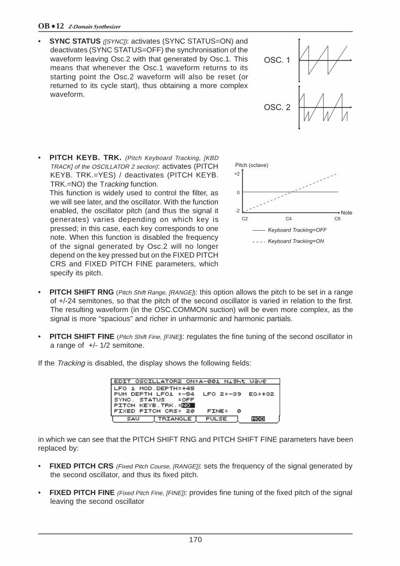
OB 12 Z-Domain Synthesizer
170
• SYNC STATUS ([SYNC]): activates (SYNC STATUS=ON) anddeactivates (SYNC STATUS=OFF) the synchronisation of thewaveform leaving Osc.2 with that generated by Osc.1. Thismeans that whenever the Osc.1 waveform returns to itsstarting point the Osc.2 waveform will also be reset (orreturned to its cycle start), thus obtaining a more complexwaveform.
• PITCH KEYB. TRK. (Pitch Keyboard Tracking, [KBDTRACK] of the OSCILLATOR 2 section): activates (PITCHKEYB. TRK.=YES) / deactivates (PITCH KEYB.TRK.=NO) the Tracking function.This function is widely used to control the filter, aswe will see later, and the oscillator. With the functionenabled, the oscillator pitch (and thus the signal itgenerates) varies depending on which key ispressed; in this case, each key corresponds to onenote. When this function is disabled the frequencyof the signal generated by Osc.2 will no longerdepend on the key pressed but on the FIXED PITCHCRS and FIXED PITCH FINE parameters, whichspecify its pitch.
• PITCH SHIFT RNG (Pitch Shift Range, [RANGE]): this option allows the pitch to be set in a rangeof +/-24 semitones, so that the pitch of the second oscillator is varied in relation to the first.The resulting waveform (in the OSC.COMMON suction) will be even more complex, as thesignal is more “spacious” and richer in unharmonic and harmonic partials.
• PITCH SHIFT FINE (Pitch Shift Fine, [FINE]): regulates the fine tuning of the second oscillator ina range of +/- 1/2 semitone.
If the Tracking is disabled, the display shows the following fields:
in which we can see that the PITCH SHIFT RNG and PITCH SHIFT FINE parameters have beenreplaced by:
• FIXED PITCH CRS (Fixed Pitch Course, [RANGE]): sets the frequency of the signal generated bythe second oscillator, and thus its fixed pitch.
• FIXED PITCH FINE (Fixed Pitch Fine, [FINE]): provides fine tuning of the fixed pitch of the signalleaving the second oscillator
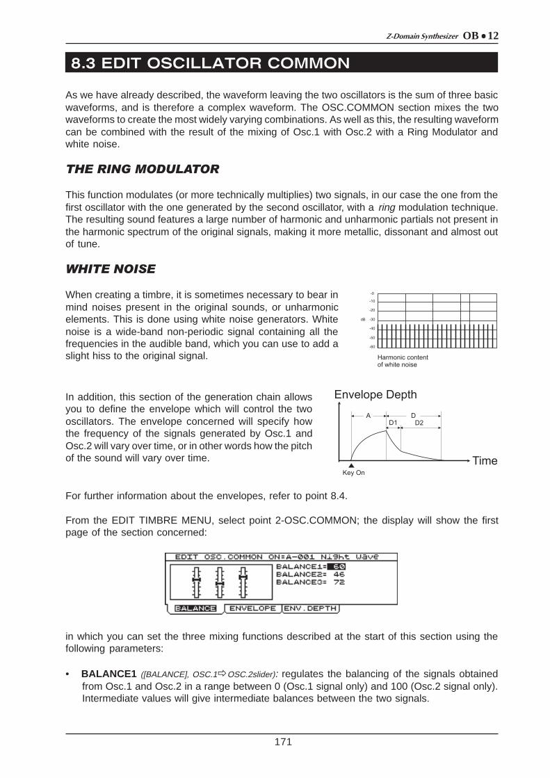
OB 12Z-Domain Synthesizer
8.3 EDIT OSCILLATOR COMMON
171
As we have already described, the waveform leaving the two oscillators is the sum of three basicwaveforms, and is therefore a complex waveform. The OSC.COMMON section mixes the twowaveforms to create the most widely varying combinations. As well as this, the resulting waveformcan be combined with the result of the mixing of Osc.1 with Osc.2 with a Ring Modulator andwhite noise.
THE RING MODULATOR
This function modulates (or more technically multiplies) two signals, in our case the one from thefirst oscillator with the one generated by the second oscillator, with a ring modulation technique.The resulting sound features a large number of harmonic and unharmonic partials not present inthe harmonic spectrum of the original signals, making it more metallic, dissonant and almost outof tune.
WHITE NOISE
When creating a timbre, it is sometimes necessary to bear inmind noises present in the original sounds, or unharmonicelements. This is done using white noise generators. Whitenoise is a wide-band non-periodic signal containing all thefrequencies in the audible band, which you can use to add aslight hiss to the original signal.
In addition, this section of the generation chain allowsyou to define the envelope which will control the twooscillators. The envelope concerned will specify howthe frequency of the signals generated by Osc.1 andOsc.2 will vary over time, or in other words how the pitchof the sound will vary over time.
For further information about the envelopes, refer to point 8.4.
From the EDIT TIMBRE MENU, select point 2-OSC.COMMON; the display will show the firstpage of the section concerned:
in which you can set the three mixing functions described at the start of this section using thefollowing parameters:
• BALANCE1 ([BALANCE], OSC.1ðOSC.2slider): regulates the balancing of the signals obtainedfrom Osc.1 and Osc.2 in a range between 0 (Osc.1 signal only) and 100 (Osc.2 signal only).Intermediate values will give intermediate balances between the two signals.

OB 12 Z-Domain Synthesizer
172
• BALANCE2 ([BALANCE], RING MOD slider): regulates the quantity of signal obtained from the firstbalancing block which will be modulated by the Ring Modulator, in a range of values from 0(no modulation by the Ring Modulator) to 100 (signal totally modulated by the Ring Modulator).Intermediate values will give intermediate quantities of modulated signal.
• BALANCE3 ([BALANCE], NOISE slider): sets the balancing between the signal obtained from thesecond balancing function and the white noise in a range of values between 0 (no whitenoise) and 100 (white noise only). Intermediate values will give intermediate balances betweenthe two signals.
We will now move on to setting of the envelope dedicated to the two oscillators (described by thediagram at the start of the section). When the ENVELOPE folder is selected, the display willchange to:
Containing the following programming parameters:
• ATTACK TIME ([ATTACK] in the OSCILLATOR COMMON section): sets the envelope attack time, i.e.the time from when the key is pressed to when the maximum pitch modification is reached, ina range of values from 0 (no attack time) to 100 (maximum attack time).
• DECAY1 TIME ([DECAY] in the OSCILLATOR COMMON section): sets the first portion of the envelopedecay time, or the time from when the oscillator reaches the maximum degree of pitchmodification to when the minimum level of DECAY1 is reached.
• DECAY1 LEVEL : regulates the level of the breakpoint between the DECAY1 and DECAY2segments, thus allowing the use of two different time values for the envelope decay. Therange of values is from -50 (pitch modification level the other side of zero from that reachedwith the ATTACK TIME segment) to +50 (pitch modification level identical to the maximumreached with the ATTACK TIME, throughout the duration of DECAY1). If this parameter is setas 0, the pitch modification will be annulled, with consequent elimination of the DECAY2segment (the envelope is thus concluded).
• DECAY2 TIME: sets the second portion of the envelope decay time, or the time from when thepitch modification reaches the value specified by DECAY1 LEVEL to when the pitch modificationis annulled. The range of values assumed by this parameter is from 0 (DECAY2 time portionabsent and pitch modification annulled when the modification reaches the DECAY1 LEVEL)and 100 (maximum time value for the second decay portion).
Now select the ENV.DEPTH (Envelope Depth) folder; the video page relating to regulation of theenvelope depth, separately for the two oscillators, will appear:

OB 12Z-Domain Synthesizer
8. 4 EDIT FILTERS
173
containing the following parameters:
• OSCILLATOR1 ([ENV DEPTH] assigned to OSC.1): regulates the depth of the envelope, or theamount by which the pitch of the signal generated by the first oscillator will vary over time, ina range of values of +50 (maximum envelope, i.e. maximum pitch variation), 0 (no envelope,i.e. pitch variation zero) and –50 (maximum negative envelope).
• OSCILLATOR2 ([ENV DEPTH] assigned to OSC.2): regulates the depth of the envelope, or theamount by which the pitch of the signal generated by the second oscillator will vary over time,in a range of values of +50 (maximum envelope, i.e. maximum pitch variation), 0 (no envelope,i.e. pitch variation zero) and –50 (maximum negative envelope).
As we have seen in section 5, which explains how sound is generated, the OB-12 emulates thesubtractive synthesis technique for sound generation. With this type of synthesis, the timbre iscreated starting from a waveform with a high harmonic content (in our case, the sum of the signalproduced by the two oscillators, the Ring Modulator, white noise and the modulations of thevarious signals) which is then filtered to eliminate or attenuate the superfluous and/or unwantedharmonics.The name “subtractive synthesis” therefore derives from the fact that harmonics are subtractedby a filter.
Analog synthesizers used normally to use VCFs (Voltage Controlled Filters), with voltage controlused to vary the cut-off frequency. This allowed real-time control from a panel, and above all byan envelope generator.In modern synthesizers VCFs have been supplanted by DCFs (Digitally Controlled Filters), whichnot only guarantee immunity from noise, but also offer unlimited flexibility of use. DCFs are producedin software version with DSPs (Digital Signal Processors).
Let us see, for example, how a square waveform is modified by the action of the filter in thevarious mode and cut-off frequency configurations:
Naturally, the above diagrams are only an example of the waveform leaving the filter, since as wehave seen, the waveforms generated by the two oscillators are much more complex.

OB 12 Z-Domain Synthesizer
174
Naturally, the above diagrams are only an example of the waveform leaving the filter, since as wehave seen, the waveforms generated by the two oscillators are much more complex.
The OB-12 makes available two filters, with total configuration with regard to their type (low pass,band pass and high pass) and parameters of use.
As can be seen, the two filters can be set as:
• LOW PASS (LP) : high pass filter which attenuates all the frequencies above the cut-offfrequency. This attenuating action will affect all the harmonics above those present at the cut-off frequency, thus giving the sound a darker and/or softer timbre.
• HIGH PASS (HP): high pass filter which attenuates all the frequencies below the cut-offfrequency. Therefore, all the harmonics below those which coincide with the cut-off frequencyare attenuated; the resulting sound will be sharper and brighter.
• BAND PASS (BP) : band pass filter which attenuates all the frequencies not present in a bandhaving its centre at the cut-off frequency.
• FLAT (no LED on) : in this case the filter is not enabled and does not operate in any frequencyarea.
In addition to this, the user can set the envelope of the two filters, meaning how the filter cut-offfrequency will change, thus regulating the timbre of the sound in relation to time.An envelope generator supplies a time curve as output in real time. This is used to pilot the threemain components of a synthesizer described previously, within the synthesis chain.
Generally the filter and amplifier are controlled (as in the OB-12) by an ADSR envelope, ADSRbeing the acronym of Attack, Decay, Sustain and Release.

OB 12Z-Domain Synthesizer
175
An ADSR envelope is therefore subdivided into:
- ATTACK Time: the time which passes from when a key is pressed to when the maximum levelis reached.
- DECAY Time: the time taken to pass from the maximum level to the SUSTAIN level:
- SUSTAIN Level: the level at which the signal remains as long as the key is kept pressed.
- RELEASE Time: time the level takes to return to zero once the key has been released.
In this example we have been talking about “level”: as we will see, when we are dealing with thefilter, this is really the operating frequency of the filter. The envelope which controls a signal levelis applied to the amplifier (see point 8.5).
But now we will move on to the Filters section programming pages.From the EDIT TIMBRE MENU, select field 5-FILTER and the display will show:
containing the following programming parameters:
• FILTER1 ([FILTER 1]): sets the type of the first filter by means of the values LOW PASS, BANDPASS, HIGH PASS and FLAT, already described.
• F.1 FREQ. (Filter 1 Frequency, [FREQUENCY]): regulates the cut-off frequency of the first filter, incorrespondence with the point of origin of the envelope.
• FILTER2 ([FILTER 2]): sets the type of the second filter by means of the values LOW PASS,BAND PASS, HIGH PASS and FLAT, already described.
• F.2 DELTA (Filter 2 Ratio): sets the variation (Delta), in semitones, of the cut-off frequency of thesecond filter compared to that of the first filter. The values cover a range from –96 (eightoctaves below F.1 Freq.) to +24 (two octaves above F.1 Freq.).
• RESONANCE ([RESONANCE]): sets the resonance coefficient of the filter, which can be usedto emphasise (enhance) the harmonics present in the cut-off frequency area, to create amore distinct sound. The values which can be assigned to this parameter range from 0 (noresonance) to 100 (maximum resonance). Look at this graphics on par. 7.4 for a clearerunderstanding of the resonance effect.
Now select the DEPTH folder and the display will show:

OB 12 Z-Domain Synthesizer
176
containing the present parameters:
• ENVELOPE DEPTH ([ENV DEPTH] of the FILTERS section): regulates the depth of the envelopeapplied to the filters in a range of values from +50 (maximum envelope, so maximum variationof the sound timbre), 0 (no envelope, so no variation of the sound timbre) and -50 (maximumnegative envelope).
• LFO1 DEPTH ([LFO1 DEPTH] of the FILTERS section): regulates the depth of modulation of thesignal originating from LFO1 on the timbre of the signal leaving the FILTERS section, bymodifying the filter cut-off frequencies and varying them continuously. The range of values isfrom +50 (maximum modulation), 0 (no modulation), +50 (maximum modulation with phasethe reverse of the signal obtained from LFO1).
• KEYB. TRACKING (Keyboard Tracking, [KBD TRACK] of the FILTERS section): Sets the keyboardtracking depth relative to the cut-off frequency of the filters depending on which key has beenpressed on the keyboard. In the case of a low pass filter, values close to zero mean that thecut-off frequency remains the same across the entire keyboard range. This means that highernotes will provide a softer sound than the lower notes, with fewer partials. When the parameteris set with values close to +50 there will be an increase in the harmonics in the higher notes,so that they will be brighter while the lower notes are darker. Conversely, if the parameter isset with values close to -50 the higher notes will have even fewer harmonics than in thestandard configuration (trimmer in central position). Therefore, the lower notes will be brighter,while the higher notes will be darker.
• F.1 FREQUENCY (Filter 1 Frequency, [FREQUENCY]): parameter identical to the parameter of thesame name in the FILTERS video page, which sets the cut-off frequency of the first filter atthe envelope point of origin. It is also displayed in this video page to allow faster programmingof this section.
If we now select the ROUTING folder, it will be possible to display the parameters relating to theconnection configuration of the two filters.
• ROUTING ([ROUTING]): sets the connection between the two filters, using the values:
- SERIAL: serial connection (previous video page);- PARALLEL: parallel connection
containing the parameter:
• BALANCE : regulates the balancing of the signal from the OSC.COMMON section, to be sentseparately to the two filters. If BALANCE=0 is set, the signal will be sent only to FILTER 1,with BALANCE=100 the signal will only be present on FILTER 2. Intermediate values of

OB 12Z-Domain Synthesizer
177
this parameter will provide intermediate balances between the quantities of signal sent withoutdistinction to the two filters.
- SPLIT: connection in which the user can set which signal will be sent individually to the twofilters.
containing the following parameters:
• BALANCE : regulates the balancing of the signal from the section specified by means of theFILTER 1 IN and FILTER 2 IN parameters, to be sent separately to the two filters. If BALANCE=0is set, the signal will be sent only to FILTER 1, with BALANCE=100 the signal will only bepresent on FILTER 2. Intermediate values of this parameter will provide intermediate balancesbetween the quantities of signal sent without distinction to the two filters.
• FILTER 1 IN: selects the source section from which the signal to be sent to FILTER 1 is to beobtained.
• FILTER 2 IN: selects the source section from which the signal to be sent to FILTER 2 is to beobtained.
The values which can be assigned to the FILTER 1 IN and FILTER 2 IN are as follows:
- OSC MIX: signal obtained from both the oscillators, added (when desired) to the RingModulator and white noise.- OSC 1: signal obtained from the first oscillator.- OSC 2: signal obtained from the second oscillator.- RING MOD: signal obtained from the ring modulator (Ring Modulator of the OSC.COMMONsection).- NOISE: while noise only (Noise of the OSC.COMMON section).
If the NEXT function is now selected, the display will show the two pages relating to theprogramming of the envelope to be applied to the filters.
The first page comprises:
containing the following programming parameters:
• ATTACK ([ATTACK] of the FILTERS section): sets the time in which the filters reach the maximumcut-off frequency once the key has been pressed, with values from 0 (no attack time) to 100(maximum attack time).
• DECAY 1 ([DECAY] of the FILTERS section): regulates the first decay time, or a first section of
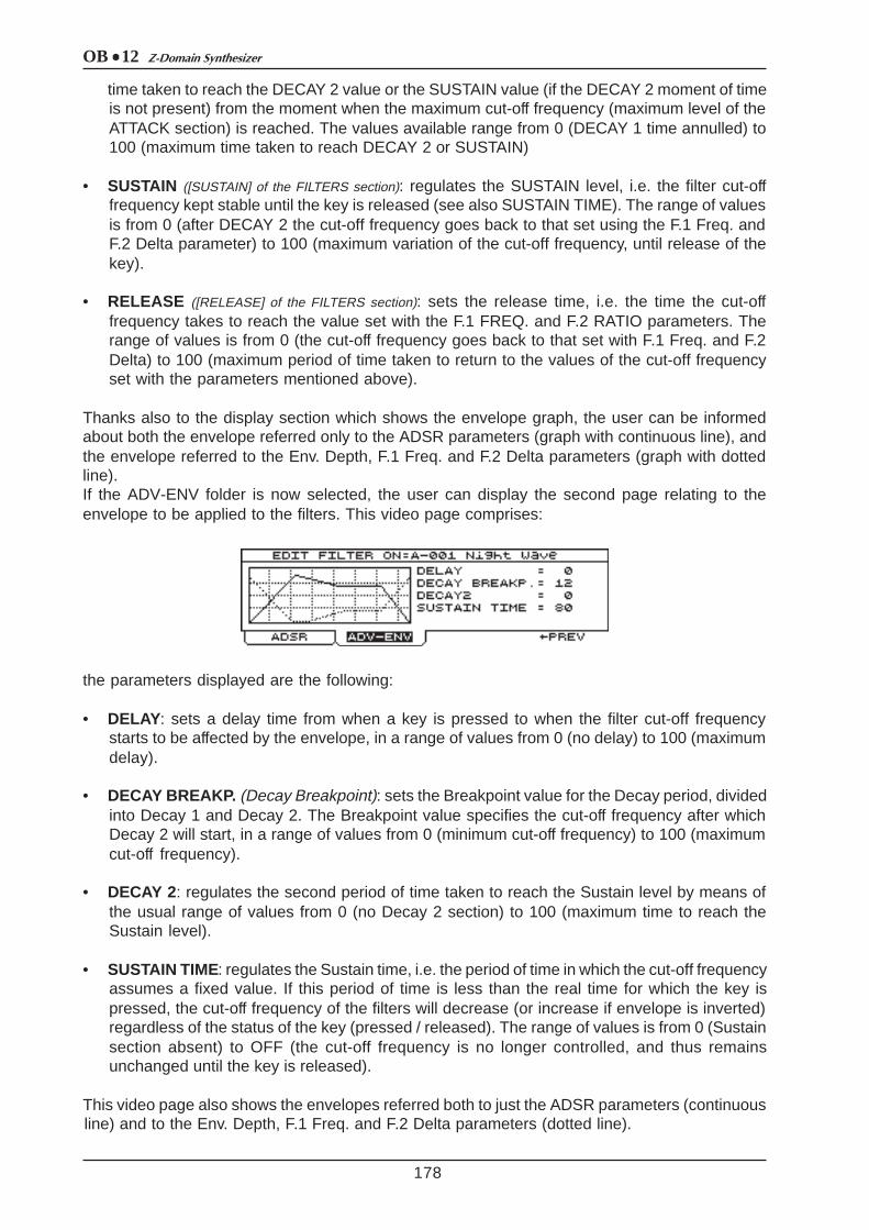
OB 12 Z-Domain Synthesizer
178
time taken to reach the DECAY 2 value or the SUSTAIN value (if the DECAY 2 moment of timeis not present) from the moment when the maximum cut-off frequency (maximum level of theATTACK section) is reached. The values available range from 0 (DECAY 1 time annulled) to100 (maximum time taken to reach DECAY 2 or SUSTAIN)
• SUSTAIN ([SUSTAIN] of the FILTERS section): regulates the SUSTAIN level, i.e. the filter cut-offfrequency kept stable until the key is released (see also SUSTAIN TIME). The range of valuesis from 0 (after DECAY 2 the cut-off frequency goes back to that set using the F.1 Freq. andF.2 Delta parameter) to 100 (maximum variation of the cut-off frequency, until release of thekey).
• RELEASE ([RELEASE] of the FILTERS section): sets the release time, i.e. the time the cut-offfrequency takes to reach the value set with the F.1 FREQ. and F.2 RATIO parameters. Therange of values is from 0 (the cut-off frequency goes back to that set with F.1 Freq. and F.2Delta) to 100 (maximum period of time taken to return to the values of the cut-off frequencyset with the parameters mentioned above).
Thanks also to the display section which shows the envelope graph, the user can be informedabout both the envelope referred only to the ADSR parameters (graph with continuous line), andthe envelope referred to the Env. Depth, F.1 Freq. and F.2 Delta parameters (graph with dottedline).If the ADV-ENV folder is now selected, the user can display the second page relating to theenvelope to be applied to the filters. This video page comprises:
the parameters displayed are the following:
• DELAY: sets a delay time from when a key is pressed to when the filter cut-off frequencystarts to be affected by the envelope, in a range of values from 0 (no delay) to 100 (maximumdelay).
• DECAY BREAKP. (Decay Breakpoint): sets the Breakpoint value for the Decay period, dividedinto Decay 1 and Decay 2. The Breakpoint value specifies the cut-off frequency after whichDecay 2 will start, in a range of values from 0 (minimum cut-off frequency) to 100 (maximumcut-off frequency).
• DECAY 2: regulates the second period of time taken to reach the Sustain level by means ofthe usual range of values from 0 (no Decay 2 section) to 100 (maximum time to reach theSustain level).
• SUSTAIN TIME: regulates the Sustain time, i.e. the period of time in which the cut-off frequencyassumes a fixed value. If this period of time is less than the real time for which the key ispressed, the cut-off frequency of the filters will decrease (or increase if envelope is inverted)regardless of the status of the key (pressed / released). The range of values is from 0 (Sustainsection absent) to OFF (the cut-off frequency is no longer controlled, and thus remainsunchanged until the key is released).
This video page also shows the envelopes referred both to just the ADSR parameters (continuousline) and to the Env. Depth, F.1 Freq. and F.2 Delta parameters (dotted line).

OB 12Z-Domain Synthesizer
8.5 EDIT AMPLIFIER
179
The main function of an amplifier is to control the level of the signals received from the oscillatorsand the filters. Amplifiers may be Voltage Controlled Amplifiers (VCAs) or, as in the OB-12, DigitallyControlled Amplifiers (DCAs).VCAs consist of operational or differential amplifiers, while in the case of DCAs, since all it takesto amplify a digital wave is to multiply its numerical width values by a given factor, amplification iscarried out by applying a width modulation to the oscillators. However, it is preferable to the keepthe two blocks (oscillator and amplifier) conceptually separate, for the sake of clarity.
As for the filter, an ADSR envelope (described in point 8.4) can be used to check the level of thesignal for amplification over time.
We will therefore now take a look at the display pages relating to programming of the amplifierparameters. From the EDIT TIMBRE MENU page, select option 6-AMPLIFIER:
containing the following controls:
• ATTACK ([ATTACK] of the AMPLIFIER section): sets the time the signal takes to reach its maximumlevel once a note has been played. The values available range from 0 (no ATTACK time) to100 (maximum ATTACK time).
• DECAY 1 ([DECAY] of the AMPLIFIER section): regulates the time taken to reach the SUSTAIN level(or DECAY 2 level, if present) from the maximum level. The range of values is from 0 (noDECAY time (to 100 (maximum DECAY time).
• SUSTAIN ([SUSTAIN] of the AMPLIFIER section): sets the SUSTAIN level, or the level the signalmaintains until the key is released (unless the SUSTAIN TIME is shorter than this period). Therange of values is from 0 (no signal after the DECAY) to 100 (maximum signal level, until thekey is released).
• RELEASE ([RELEASE] of the AMPLIFIER section): sets the time taken for the signal level to beannulled after the key is released, in a range of values from 0 (no signal on release of the key)to 100 (maximum signal release time).
You can now select the ADV-ENV folder to access the second page for programming of theenvelope applied to the amplifier:
Featuring the following parameters:
• DELAY: sets a delay time from when a key is pressed to when the signal level starts to be
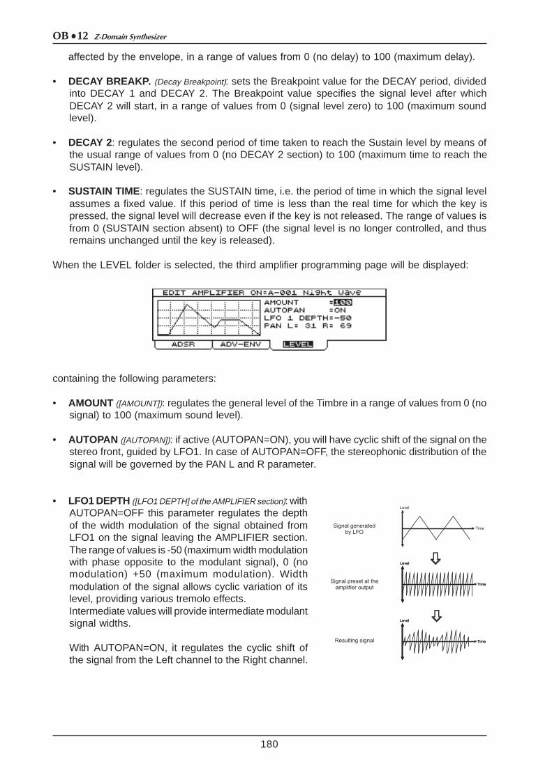
OB 12 Z-Domain Synthesizer
180
affected by the envelope, in a range of values from 0 (no delay) to 100 (maximum delay).
• DECAY BREAKP. (Decay Breakpoint): sets the Breakpoint value for the DECAY period, dividedinto DECAY 1 and DECAY 2. The Breakpoint value specifies the signal level after whichDECAY 2 will start, in a range of values from 0 (signal level zero) to 100 (maximum soundlevel).
• DECAY 2: regulates the second period of time taken to reach the Sustain level by means ofthe usual range of values from 0 (no DECAY 2 section) to 100 (maximum time to reach theSUSTAIN level).
• SUSTAIN TIME: regulates the SUSTAIN time, i.e. the period of time in which the signal levelassumes a fixed value. If this period of time is less than the real time for which the key ispressed, the signal level will decrease even if the key is not released. The range of values isfrom 0 (SUSTAIN section absent) to OFF (the signal level is no longer controlled, and thusremains unchanged until the key is released).
When the LEVEL folder is selected, the third amplifier programming page will be displayed:
containing the following parameters:
• AMOUNT ([AMOUNT]): regulates the general level of the Timbre in a range of values from 0 (nosignal) to 100 (maximum sound level).
• AUTOPAN ([AUTOPAN]): if active (AUTOPAN=ON), you will have cyclic shift of the signal on thestereo front, guided by LFO1. In case of AUTOPAN=OFF, the stereophonic distribution of thesignal will be governed by the PAN L and R parameter.
• LFO1 DEPTH ([LFO1 DEPTH] of the AMPLIFIER section): withAUTOPAN=OFF this parameter regulates the depthof the width modulation of the signal obtained fromLFO1 on the signal leaving the AMPLIFIER section.The range of values is -50 (maximum width modulationwith phase opposite to the modulant signal), 0 (nomodulation) +50 (maximum modulation). Widthmodulation of the signal allows cyclic variation of itslevel, providing various tremolo effects.Intermediate values will provide intermediate modulantsignal widths.
With AUTOPAN=ON, it regulates the cyclic shift ofthe signal from the Left channel to the Right channel.

OB 12Z-Domain Synthesizer
8.6 EDIT LFO1
181
• PAN L and R: sets the distribution over the stereo panorama of the signal leaving theAMPLIFIER section, and thus of the final Timbre sound.
The main function of an LFO (Low Frequency Oscillator) is to generate a low frequency signalwhich can be used as modulant for the signals leaving the synthesizer’s main blocks, such as theoscillators, the filter and the amplifier.The OB-12 allows not only regulation of the frequency of the output signal, but also setting of itswaveform and regulation of its envelope and the parameters of a low-pass filter associated to theLFO.Discussing the parameters relating to the OB-12 sections, we have already discussed the effectsobtained by modulating the sound leaving the blocks referred to above using the signal obtainedfrom LFO1 and LFO2.We will therefore now look at the programming pages of the first LFO. From the usual EDITTIMBRE MENU page, select field 1-EDIT LFO1. The display will show:
SAW: sawtooth waveform; TRIANGLE: triangular waveform;
SQUARE: square waveform; RANDOM: waveform which assumes randomlevels;
• WAVE TYPE ([WAVE SELECT]): sets the waveform of the signal leaving the first LFO. Thepossible choices are:
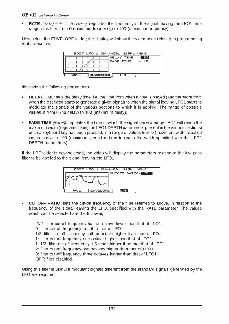
OB 12 Z-Domain Synthesizer
182
• RATE ([RATE] of the LFO1 section): regulates the frequency of the signal leaving the LFO1, in arange of values from 0 (minimum frequency) to 100 (maximum frequency).
Now select the ENVELOPE folder; the display will show the video page relating to programmingof the envelope:
displaying the following parameters:
• DELAY TIME: sets the delay time, i.e. the time from when a note is played (and therefore fromwhen the oscillator starts to generate a given signal) to when the signal leaving LFO1 starts tomodulate the signals of the various sections to which it is applied. The range of possiblevalues is from 0 (no delay) to 100 (maximum delay).
• FADE TIME ([FADE]): regulates the time in which the signal generated by LFO1 will reach themaximum width (regulated using the LFO1 DEPTH parameters present in the various sections)once a keyboard key has been pressed, in a range of values from 0 (maximum width reachedimmediately) to 100 (maximum period of time to reach the width specified with the LFO1DEPTH parameters).
If the LPF folder is now selected, the video will display the parameters relating to the low-passfilter to be applied to the signal leaving the LFO1:
• CUTOFF RATIO: sets the cut-off frequency of the filter referred to above, in relation to thefrequency of the signal leaving the LFO, specified with the RATE parameter. The valueswhich can be selected are the following:
-1/2: filter cut-off frequency half an octave lower than that of LFO1.0: filter cut-off frequency equal to that of LFO1.1/2: filter cut-off frequency half an octave higher than that of LFO1.1: filter cut-off frequency one octave higher than that of LFO1.1+1/2: filter cut-off frequency 1.5 times higher than that that of LFO1.2: filter cut-off frequency two octaves higher than that of LFO1.3: filter cut-off frequency three octaves higher than that of LFO1.OFF: filter disabled.
Using this filter is useful if modulant signals different from the standard signals generated by theLFO are required.

OB 12Z-Domain Synthesizer
8.7 EDIT LFO2
183
As for LFO1, LFO2 allows you to modulate the signal in the various generation sections of theOB-12 with a low frequency signal. The main feature of the second low frequency oscillator isthat the quantity of modulation can be regulated by means of the [MODULATION] wheel on theleft of the keyboard.
From the EDIT TIMBRE MENU, select option 7 – EDIT LFO2. The display will show:
This video page contains the following programming parameters:
• WAVE TYPE ([WAVE SELECT] of the LFO2 section): sets the waveform of the signal leaving LFO2.The possible choices are:
SAW: sawtooth waveform;TRIANGLE: triangular waveform;SQUARE: square waveform;RANDOM: waveform which assumes random levels;
• RATE ([RATE] of the LFO2 section): regulates the frequency of the signal leaving LFO2 in a rangeof values from 0 (minimum frequency) to 100 (maximum frequency).
If the DEPTH folder is now selected, the display will show the parameters for regulating thequantity of modulation to be applied to the various sections:
• DEPTH ON OSC 1 ([DEPTH] with [DEPTH SELECT] on OSC 1): regulates the depth of the frequencymodulation by LFO2 on the signal leaving Osc. 1.
• DEPTH ON OSC 2 ([DEPTH] with [DEPTH SELECT] on OSC 2): regulates the depth of the frequencymodulation by LFO2 on the signal leaving Osc. 2.
• DEPTH ON FILT. (Depth on Filters, [DEPTH] with [DEPTH SELECT] on FILTERS): regulates the modulationdepth by LFO2 on the signal leaving the Filters section.
• DEPTH ON AMP. (Depth on Amplifier, [DEPTH] with [DEPTH SELECT] on AMPLIFIER): regulates thedepth of the width modulation by LFO2 on the signal leaving the Amplifier section.
If the LPF folder is now selected, the video will display the parameters relating to the low-passfilter to be applied to the signal leaving the LFO2.

OB 12 Z-Domain Synthesizer
8.8 EDIT KEYBOARD MODE
184
• CUTOFF RATIO: sets the cut-off frequency of the filter referred to above, in relation to thefrequency of the signal leaving the LFO, specified with the RATE parameter. The valueswhich can be selected are the following:
-1/2: filter cut-off frequency half an octave lower than that of LFO2.0: filter cut-off frequency equal to that of LFO2.1/2: filter cut-off frequency half an octave higher than that of LFO2.1: filter cut-off frequency one octave higher than that of LFO2.1+1/2: filter cut-off frequency 1.5 times higher than that that of LFO2.2: filter cut-off frequency two octaves higher than that of LFO2.3: filter cut-off frequency three octaves higher than that of LFO2.OFF: filter disabled.
The purpose of the KEYBOARD MODE section is to set the modes of the keyboard and itstransposition. This allows use of the Portamento and Unison function, set the keyboard inmonophonic mode (with addition of Legato) or polyphonic mode, and regulate the transpositionof the oscillators (and thus of the notes played on the keyboard). From the EDIT TIMBRE MENUvideo page, select the 8-MODE field and the display will show the following editing page:
containing the following parameters:
• PORTAM.STATUS (Portamento Status, [PORTAMENTO]): enables or disables the Portamentofunction. Portamento allows you to make changes in pitch between a note and the one playedafter it within a given period of time and not simultaneously with the pressure on the key, sothat the intermediate tones are produced.
• PORTAM.TIME (Portamento Time, [TIME]): sets the time of the Portamento, meaning the continuouschange in pitch between a note and the one played after it.
For a clearer understanding of this function, look at the illustration below:
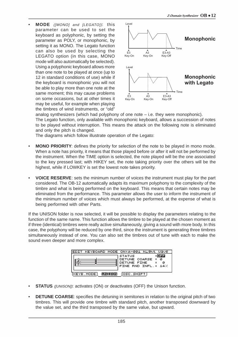
OB 12Z-Domain Synthesizer
185
• MODE ([MONO] and [LEGATO]): thisparameter can be used to set thekeyboard as polyphonic, by setting theparameter as POLY, or monophonic, bysetting it as MONO. The Legato functioncan also be used by selecting theLEGATO option (in this case, MONOmode will also automatically be selected).Using a polyphonic keyboard allows morethan one note to be played at once (up to12 in standard conditions of use) while ifthe keyboard is monophonic you will notbe able to play more than one note at thesame moment; this may cause problemson some occasions, but at other times itmay be useful, for example when playingthe timbres of wind instruments, or “old”analog synthesizers (which had polyphony of one note – i.e. they were monophonic).The Legato function, only available with monophonic keyboard, allows a succession of notesto be played without interruption. This means the attack on the following note is eliminatedand only the pitch is changed.The diagrams which follow illustrate operation of the Legato:
• MONO PRIORITY: defines the priority for selection of the note to be played in mono mode.When a note has priority, it means that those played before or after it will not be performed bythe instrument. When the TIME option is selected, the note played will be the one associatedto the key pressed last; with HIKEY set, the note taking priority over the others will be thehighest, while if LOWKEY is set the lowest note takes priority.
• VOICE RESERVE: sets the minimum number of voices the instrument must play for the partconsidered. The OB-12 automatically adapts its maximum polyphony to the complexity of thetimbre and what is being performed on the keyboard. This means that certain notes may beeliminated from the performance. This parameter allows the user to inform the instrument ofthe minimum number of voices which must always be performed, at the expense of what isbeing performed with other Parts.
If the UNISON folder is now selected, it will be possible to display the parameters relating to thefunction of the same name. This function allows the timbre to be played at the chosen moment asif three (identical) timbres were really active simultaneously, giving a sound with more body. In thiscase, the polyphony will be reduced by one third, since the instrument is generating three timbressimultaneously instead of one. You can also set the timbres out of tune with each to make thesound even deeper and more complex.
• STATUS ([UNISON]): activates (ON) or deactivates (OFF) the Unison function.
• DETUNE COARSE: specifies the detuning in semitones in relation to the original pitch of twotimbres. This will provide one timbre with standard pitch, another transposed downward bythe value set, and the third transposed by the same value, but upward.

OB 12 Z-Domain Synthesizer
8.9 EDIT CONTROLLERS
186
• DETUNE FINE: regulates the fine transposition of the three timbres in hundredths. Thistransposition is applied to the timbres as for the DETUNE COARSE parameter.
• FINE RND INFL. (Fine Random Influence): specifies as a percentage by how much the pitch of thethree timbres (specified using the (DETUNE COARSE and DETUNE FINE parameters) willbe modified.
You can now use the [F3] associated to the OSC.SHIFT folder to display the video page relatingto the transposition by octaves of the two oscillators individually. This allows you to use the twooscillators transposed by up to four octaves apart, creating deeper, more complex sounds, toplay beyond the keyboard range (in both bass and treble direction) and to use different pitches inthe various Parts which make up a given Program (to allow this, the TRANSPOSE parameterassociated to the Part in question can also be used).
The video page consists of the following parameters:
• OSC 1 SHIFT ([OCT-] and/or [OCT+] with [OSC SHIFT] on OSC 1): increases or decreases the pitchof the first oscillator in a range of two octaves.
• OSC 2 SHIFT ([OCT-] and/or [OCT+] with [OSC SHIFT] on OSC 2): increases or decreases the pitchof the first oscillator in a range of two octaves.
N.B.: When the oscillators are transposed, the MIDI Note On and Note Off messages received bythe MIDI [IN] port will be played on the basis of the transposition carried out.Conversely, the Note On messages (since the Note Off is sent like Note On with Velocity=0) sentto the MIDI [OUT] port will not be affected by the transposition.
Thanks to the Velocity and Aftertouch-sensitive OB-12 keyboard, the CONTROLLERS section ofthe EDIT TIMBRE MENU allows specific generation control parameters to be assigned to theVelocity, the Aftertouch and the Ribbon Controller, and enabling and disabling of the [PITCH]and [MODULATION] wheels.
N.B.: the Ribbon Controller, the Velocity and the Aftertouch are controlling the assigned parametersaccording to the value of the parameter when assigning a parameter with 0 value, the concerningcontrol will not have any sound variation
From the EDIT TIMBRE MENU select field 9-CONTROLLERS and the display will show the videopage relating to the assignment of parameters to the Velocity.The Velocity (dynamic) is the speed at which the keyboard key is pressed and released. Thisfunction therefore allows you to play the keyboard keys in a way which gives extra expressivenessto the timbres, without having to use the panel controls. Normally the note velocity is associated tothe signal level, but using this function you can assign the cut-off frequency, for example, to theVelocity, in order to extend the spectrum of the timbre being played in relation to the force withwhich a key has been pressed. So in short, the huge advantage of this function is that severalparameters can be controlled without having to take your fingers off the keyboard.

OB 12Z-Domain Synthesizer
187
• STATUS ([VELOCITY ON]): enables (ON) or disables (OFF) control of the generation parametersby means of the Velocity.
• TYPE: sets the type of dynamic. A fixed dynamic can be obtained by setting the parametersas FLAT, or various dynamic curves can be obtained by selecting CURVE (see next videopage illustration).
• DYN.VALUE (Dynamic Value): regulates the value of the fixed dynamic.
• PARAMETER : selects the generation parameter for which the influence of Velocity-control isto be set by means of the INFLUENCE field.
This is the list of the parameters available and the relative panel controls:
• INFLUENCE: sets the influenced of the Velocity in controlling the parameter specified in thePARAMETER field.
If TYPE=CURVE is set, the dynamic of the notes is no longer fixed, but varies depending on thepressure on the key and the dynamic curve.
SELECTIONSCONTROLLED PARAMETERS
CONTROLS ON PANEL
SELECTIONSCONTROLLED PARAMTERS
CONTROLS ON PANEL
AMP-AMOUNT timbre level[AMOUNT] of AMPLIFIER OSCC-ATCKT
attack time of the OSC.1 and OSC.2
envelope
[ATTACK] of OSC.COMON
AMP-ATCK Tattack time of the
AMPLIFIER envelope[ATTACK] of AMPLIFIER OSCC-DEC T
decay time of the OSC.1 and OSC.2
[DECAY] of OSC.COMMON
AMP-DECAYTdecay time of the
AMPLIFIER envelope[DECAY] of AMPLIFIER OSCC-DPTH1 OSC.1 envelope depth
[ENV DEPTH] on OSC.1 of
OSC.COMMON
FLT-CUTOFF filter cut-off frequency[FREQUENCY] of
FILTER OSCC-DPTH2 OSC.2 envelope depth[ENV DEPTH] on
OSC.2 of OSC.COMMON
FLT-ATCK T attack time of the FILTERS envelope
[ATTACK] of FILTERS OSC1-PWDTH modulation depth to the OSC.1 impulse
[PWM DEPTH] of OSC.1
FLT-DECAYT decay time of the FILTERS envelope
[DECAY] of FILTERS OSC2-PWDTH modulation depth to the OSC.2 impulse
[PWM DEPTH] of OSC.2
FLT-ENVDPT FILTERS envelope depth
[ENV DEPTH] of FILTERS LFO1-FADE T time for reach the max.
level of LFO1 signal[FADE] of LFO1]
BALANCE 1balance between
OSC.1 and OSC.2[BALANCE 1] of OSC.COMMON OSC1-FM
modulation depth of OSC.2 on OSC.1
[FM] of OSCILLATOR1
BALANCE 2balance between
OSC.1+OSC.2 and RING MODULATOR
[BALANCE 2] of OSC.COMMON OSC2-DTUNE fine tuning of OSC.2 [FINE] of OSC.2
BALANCE 3
balance between OSC.1+OSC.2+RING
MODULATOR and NOISE
[BALANCE 3] of OSC.COMMON

OB 12 Z-Domain Synthesizer
188
displaying the following parameter:
• CURVE: displays the name of the dynamic curve (drawn on the left of the display) assignedto the note. The curves are as follows:
- LIGHT: Light dynamic response curve, in which the maximum dynamic values are reachedquickly.- FEEL LIGHT: Variation on the LIGHT curve, featuring a hardening in the central zone. Highdynamic values can still be reached.- LINEAR: Straight (also known as standard) curve so that the pressure applied to the key isconverted into a dynamic in direct proportion.- FEEL HEAVY: Slightly hard dynamic curve which is still fairly linear, so that the maximumdynamic values can still be reached.- HEAVY: Hard dynamic response curve, with which strong pressure has to be applied to thekey to reach high dynamic values.- CUSTOM: Custom dynamic curve which has zero response for low dynamic values appliedto the key and an almost linear response, leading to the maximum dynamic values, startingfrom medium levels of pressure applied to the key.- REVERSED1: Reversed curves reverse the logic of the dynamic; in other words, low levelsof pressure on the key give high dynamic values generated by the instrument and vice-versa.This curve has a linear but reversed trend.- REVERSED2: Reversed curve with values which remain high even with medium-strongpressures on the keyboard. When the level of force applied to the key is increased to themaximum, the dynamic generated will fall sharply.
The AFTER-T folder can now be selected to display the video page relating to setting of theAftertouch. Unlike the Velocity, the Aftertouch is the pressure applied to a given key after it hasbeen pressed.Thanks to this function, you can control several parameters after a keyboard key has been pressedby applying further pressure to the key.
containing the following parameters:
• STATUS ([AFTER ON]): activates (ON) or deactivates (OFF) the Aftertouch.
• CURVE: selects the Aftertouch curve (shown on the left of the display). The curves which canbe selected are:
- SOFT1: Light response curve which allows high Aftertouch values to be reached quickly.- SOFT2: Response curve less light than SOFT1, which still guarantees that high Aftertouchvalues are reached quickly, although in a more controllable manner.- LINEAR: Straight response curve, so that the pressure applied to the key (after it has beendepressed, naturally) is converted in linear proportion into Aftertouch data.- HEAVY1: Although a certain degree of linearity is maintained, with this curve it will be moredifficult to reach high Aftertouch values.- HEAVY2: Hard curve in which strong pressures will have to be applied to the key to reachhigh Aftertouch values.- CUSTOM: Curve with responses which are not uniform throughout the range of values. Thiscurve is soft for low levels of pressure on the key, heavy for medium values and then soft again

OB 12Z-Domain Synthesizer
189
for high pressure values.- DELAYED: Curve which delays the emission of data, which are not generated until highpressures are applied to the key, after which high Aftertouch values are reached easily.- INVERTED: Inverted Aftertouch curves have the same properties as reversed Velocity curves.
• PARAMETER : selects the generation parameter for which the influence of Aftertouch-controlis to be set by means of the INFLUENCE field.
This is the list of the parameters available and the relative panel controls:
• INFLUENCE: sets the influence of the Aftertouch in controlling the parameter specified in thePARAMETER field.
You can now use the [F3] key to select the RIBBON folder, thus displaying the video page relatingto the assignments of parameters to the Ribbon Controller.This device allows you to control both the parameters relating to sound generation by moving afinger over the surface of the control.
• FUNCTION1: assigns the first function to the Ribbon Controller.
• FUNCTION2: assigns the second function to the Ribbon Controller.
• MIN and MAX referred to FUNCTION1 and 2: set the minimum and maximum values of theparameters to which they refer.
SELECTIONSCONTROLLED PARAMETERS
CONTROLS ON PANEL
SELECTIONSCONTROLLED PARAMTERS
CONTROLS ON PANEL
AMP-AMOUNT timbre level[AMOUNT] of AMPLIFIER OSC2-LFO1D
modulation depth of LFO1 in OSC.2
[LFO1 DEPTH] of OSC.2
FLT CUTOFF filter cut-off frequency[FREQUENCY] of
FILTER FLT-LFO1 Dmodulation depth of
LFO1 in FILTER[LFO1 DEPTH] of
FILTER
BALANCE 1balance between
OSC.1 and OSC.2[BALANCE 1] of OSC.COMMON AMP-LFO1 D
modulation depth of LFO1 in AMPLIFIER
[LFO1 DEPTH] of AMPLIFIER
BALANCE 2balance between
OSC.1+OSC.2 and RING MODULATOR
[BALANCE 2] of OSC.COMMON OSC1-FM
frequency modulation depth of OSC.2 in
OSC.1[FM] of OSC.2
BALANCE 3
balance between OSC.1+OSC.2+RING
MODULATOR and NOISE
[BALANCE 3] of OSC.COMMON OSC2-DTUNE fine tuning of OSC.2 [FINE] of OSC.2
OSC1-PWDTHmodulation depth to the
OSC.1 impulse[PWM DEPTH] of
OSC.1 LFO1-RATE LFO1 signal frequency [RATE] of LFO1
OSC2-PWDTH modulation depth to the OSC.2 impulse
[PWM DEPTH] of OSC.2 LFO2-RATE LFO2 signal frequency [RATE] of LFO2
OSC1-LFO1D modulation depth of LFO1 in OSC.1
[LFO1 DEPTH] of OSC.1

OB 12 Z-Domain Synthesizer
190
Activating the MORE... folder displays the video page relating to activation or deactivation of the[PITCH] and [MODULATION] wheels. You can use [PITCH] for real-time control of the Timbrepitch, while [MODULATION] allows regulation of the modulation depth of LFO2 on the sections towhich the modulant signal is sent.
This video page displays the following parameters:
• PIT.WHEEL STATUS (Pitch Wheel Status): enables (ON) or disables (OFF) the [PITCH] wheel
• RANGE: sets the range [PITCH] in semitones.
• MOD.WHEEL STATUS (Modulation Wheel Status): enables (ON) or disables (OFF) the[MODULATION wheel.
SELECTIONSCONTROLLED PARAMETERS
CONTROLS ON PANEL
SELECTIONSCONTROLLED PARAMTERS
CONTROLS ON PANEL
SELECTIONSCONTROLLED PARAMTERS
CONTROLS ON PANEL
DISABLED none OSC1 LFO1DPmodulation depth of LFO1
on OSC.1[LFO1 DEPTH] of
OSCILLATOR1 FILT.REL.release time of the FILTERS envelope
[RELEASE] of FILTERS
LFO1-FADEtime for reach the max.
level of LFO1 signal [FADE] of LFO1] OSC1PWMLFO1pulse with modulation
depth of LFO1 on OSC.1
[PWM DEPTH] assigned to LFO1 of
OSCILLATOR1FILT.ENV.D FILTERS envelope depth
[ENV DEPTH] of FILTERS
LFO1-RATE LFO1 signal frequency [RATE] of LFO1 OSC1PWMLFO2pulse with modulation
depth of LFO2 on OSC.1
[PWM DEPTH] assigned to LFO2 of
OSCILLATOR1FILT.LFO1D
modulation depth of LFO1 on OSC.1
[LFO1 DEPTH] of FILTERS
BALANCE 1balance between OSC.1
and OSC.2[BALANCE 1] of OSC.COMMON OSC1PWMEG
pulse width modulation depth of EG on OSC.1
[PWM DEPTH] assigned to EG of
OSCILLATOR1AMPL.ATK
attack time of the AMPLIFIER envelope
[ATTACK] of AMPLIFIER
BALANCE 2balance between
OSC.1+OSC.2 and RING MODULATOR
[BALANCE 2] of OSC.COMMON OSC2 SAW LV saw wave level generated
by OSC.2
[WAVE MIX] of the saw wave of OSCILLATOR
2AMPL.DECAY decay time of the
AMPLIFIER envelope[DECAY] of AMPLIFIER
BALANCE 3balance between
OSC.1+OSC.2+RING MODULATOR and NOISE
[BALANCE 3] of OSC.COMMON OSC2 TRI.LV triangle wave level
generated by OSC.2
[WAVE MIX] of the triangle wave of OSCILLATOR2
AMPL.SUST. sustain level of the AMPLIFIER envelope
[SUSTAIN] of AMPLIFIER
OSC.COM.AT attack time of the OSC.1 and OSC.2 envelope
[ATTACK] of OSC.COMON OSC2 PUL.LV square wave level
generated by OSC.2
[WAVE MIX] of the square wave of OSCILLATOR2
AMPL.REL. release time of the AMPLIFIER envelope
[RELEASE] of AMPLIFIER
OSC.COM.DE decay time of the OSC.1 and OSC.2
[DECAY] of OSC.COMMON OSC2 PUL.WD square wave pulse width
generated by OSC.2
[OSC CTRL] assigned to square wave of
OSCILLATOR2AMPL.AMOUN Timbre level [AMOUNT] of
AMPLIFIER
OSC1COM.EN OSC.1 envelope depth[ENV DEPTH] on
OSC.1 of OSC.COMMON
OSC2 LFO1DP modulation depth of LFO1 on OSC.2
[LFO1 DEPTH] of OSCILLATOR2 AMPL.LFO1D modulation depth of LFO1
on AMPLIFIER[LFO1 DEPTH] of
AMPLIFIER
OSC2COM.EN OSC.2 envelope depth[ENV DEPTH] on
OSC.2 of OSC.COMMON
OSC2PWMLFO1 pulse with modulation depth of LFO1 on OSC.2
[PWM DEPTH] assegnato a LFO1 di
OSCILLATOR2LFO2 RATE LFO2 signal frequency [RATE] of LFO2
OSC1 SAW L saw wave level generated by OSC.1
[WAVE MIX] of the saw wave of OSCILLATOR
1OSC2PWMLFO2 pulse with modulation
depth of LFO2 on OSC.2
[PWM DEPTH] assigned to LFO2 of
OSCILLATOR2LFO2 DP.OS1 modulation depth of LFO2
on OSC.1[MODULATION]
OSC1 SAW SPsaw wave modification generated by OSC.1
[WAVE CTRL] assigned to saw wave
of OSCILLATOR1 OSC2PWMEG
pulse width modulation depth of EG on OSC.2
[PWM DEPTH] assigned to EG of
OSCILLATOR2LFO2 DP.OS2
modulation depth of LFO2 on OSC.2
[MODULATION]
OSC1 TRI.Ltriangular wave level generated by OSC.1
[WAVE MIX] of the triangular wave of OSCILLATOR1
FILT.FREQ.cut-off frequency of
FILTERS[FREQUENCY] of
FILTERS LFO2 DP.FLTmodulation depth of LFO2
on FILTERS[MODULATION]
OSC1 TRI.WRtriangle wave modification
generated by OSC.1
[WAVE CTRL] assigned to triangle
wave of OSCILLATOR1
FILT.RES. resonance of FILTERS[RESONANCE] of
FILTERS LFO2 DP.AMPmodulation depth of LFO2
on AMPLIFIER [MODULATION]
OSC1 PUL.LVsquare wave level
generated by OSC.1
[WAVE MIX] of the square wave of OSCILLATOR1
FILT.ATKattack time of the FILTERS
envelope [ATTACK] of FILTERS PORTAM.TIM Portamento time[TIME] of
PORTAMENTO
OSC1 PUL.WDsquare wave pulse width
generated by OSC.1
[OSC CTRL] assigned to square wave of OSCILLATOR1
FILT.DECAYdecay time of the FILTERS
envelope [DECAY] of FILTERS PITCH BENDtrasposition of the
notes [PITCH]
OSC1 FMmodulation depth of OSC.2
on OSC.1 [FM] of OSCILLATOR1 FILT.SUST.sustain level of the FILTERS envelope [SUSTAIN] of FILTERS

OB 12Z-Domain Synthesizer
8.10 WRITE TIMBRE
191
After making all the desired settings, you can use the WRITE TIMBRE procedure to save thetimbre you have edited in one of the 256 memory locations assigned to the Timbres. From anyTimbre environment video page, press the [WRITE] button in the MODE&SET-UP section of thefront panel, and the display will show:
The CURRENT LOCATION field displays the current memory location, and DESTINATION, theone where the Timbre will be saved. By default, the two fields offer the same memory location: inthis case, if the memorisation procedure is concluded, the timbre will be overwritten with consequentloss of the original settings.
Pressing the [F1] button or [WRITE] button will confirm the memorisation procedure, and thedisplay will show everything with the Pop-Up:
Conversely, if the [F4] button is pressed from the video page shown previously, you can assign anew name to the Timbre; in this case, the display will show:
You can now use the encoder or number keypad to assign a new name to the Timbre displayedin square brackets. As the screen-printing on the panel shows, each number pad button offersthree letters of the alphabet as well as the number associated to it. Moreover, the function keyscan be used to recall the following functions:
• INS ([F1]) function: inserts a space before the character on which the cursor is located;• CAPS ON/OFF ([F2]) function: selects the type of character (uppercase / lowercase);• DELETE ([F3]) function: deletes the character on which the cursor is located;
After typing the name of your choice, press button [F4] (DONE function), and assignment of thenew name will be completed.

OB 12 Z-Domain Synthesizer
9. EDIT PROGRAM
192
As we have already explained in point 5.2, a Program is able to contain up to four Timbres. This ispossible because the Program can be divided into Parts, to which a given Timbre, a given portionof the keyboard and a specific function of the pedal connected to the rear connectors can beassigned.
As for the TIMBRE operating environment, you can also define the various functions associated tothe PROGRAM.Display the PLAY PROGRAM video page using the [PROGRAM] button in the MODE & SET-UPsection of the central panel:
The functions of the INFOS and SCOPE folders have already been explained in point 6.1. We willnow examine the functions used to set a Program. Press button [F4] to select the EDIT field; thedisplay will show the EDIT PROGRAM MENU:
in which you can recall the following functions:
1-PART SETTINGS : definition of the Parts and their assignment to the keyboard zones.2-BUS SETTINGS: assignments of the outputs present on the rear panel to the Parts.3-EFFECTS: activation and regulation of the effects and their connection.4-EQUALIZER: setting of the equalizer.5-LINKS: setting of the LINKS function.6-FOOT CTRL: assignment of the functions to the pedals.7-ARPEGGIO: setting of the ARPEGGIO function.8-PHRASE REC: regulation of the PHRASE RECORDER function.9-AUTO MORPH SET: regulation of the MORPH function.0-KEYB. TRANSPOSER : definition of the keyboard transposition.
Let us now take a detailed look at the functions applied to the Program.Alongside the name (or code) of the parameter whose function is being discussed, in round bracketsyou will find the full name of the panel control found in the section whose contents are beingexplained, used to modify the parameter in question. If the description of the panel control isaccompanied by reference to the section in which it is found, this means that the control in questionalso appears in other sections.
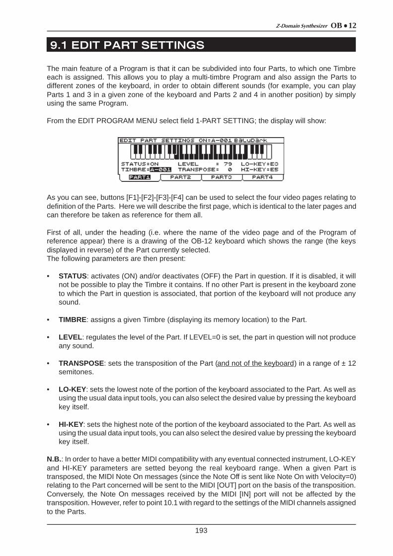
OB 12Z-Domain Synthesizer
9.1 EDIT PART SETTINGS
193
The main feature of a Program is that it can be subdivided into four Parts, to which one Timbreeach is assigned. This allows you to play a multi-timbre Program and also assign the Parts todifferent zones of the keyboard, in order to obtain different sounds (for example, you can playParts 1 and 3 in a given zone of the keyboard and Parts 2 and 4 in another position) by simplyusing the same Program.
From the EDIT PROGRAM MENU select field 1-PART SETTING; the display will show:
As you can see, buttons [F1]-[F2]-[F3]-[F4] can be used to select the four video pages relating todefinition of the Parts. Here we will describe the first page, which is identical to the later pages andcan therefore be taken as reference for them all.
First of all, under the heading (i.e. where the name of the video page and of the Program ofreference appear) there is a drawing of the OB-12 keyboard which shows the range (the keysdisplayed in reverse) of the Part currently selected.The following parameters are then present:
• STATUS: activates (ON) and/or deactivates (OFF) the Part in question. If it is disabled, it willnot be possible to play the Timbre it contains. If no other Part is present in the keyboard zoneto which the Part in question is associated, that portion of the keyboard will not produce anysound.
• TIMBRE: assigns a given Timbre (displaying its memory location) to the Part.
• LEVEL : regulates the level of the Part. If LEVEL=0 is set, the part in question will not produceany sound.
• TRANSPOSE: sets the transposition of the Part (and not of the keyboard) in a range of ± 12semitones.
• LO-KEY : sets the lowest note of the portion of the keyboard associated to the Part. As well asusing the usual data input tools, you can also select the desired value by pressing the keyboardkey itself.
• HI-KEY: sets the highest note of the portion of the keyboard associated to the Part. As well asusing the usual data input tools, you can also select the desired value by pressing the keyboardkey itself.
N.B.: In order to have a better MIDI compatibility with any eventual connected instrument, LO-KEYand HI-KEY parameters are setted beyong the real keyboard range. When a given Part istransposed, the MIDI Note On messages (since the Note Off is sent like Note On with Velocity=0)relating to the Part concerned will be sent to the MIDI [OUT] port on the basis of the transposition.Conversely, the Note On messages received by the MIDI [IN] port will not be affected by thetransposition. However, refer to point 10.1 with regard to the settings of the MIDI channels assignedto the Parts.

OB 12 Z-Domain Synthesizer
9.2 BUS SETTINGS
9.3 EDIT EFFECTS
194
This Edit Program section allows you to assign each individual Part to a given output bus. Thisenables you to exploit the extraordinary feature of having each single Part on each single connector,guaranteeing easier mixing procedures outside the instrument.Another very important feature of this section is that it interacts with the effects Routing (see point9.3 – Routing Configuration) since when a Part (and thus a Timbre) is assigned to given outputs,and the effects (or effect) is (are) placed on the buses of the outputs concerned, you can obtain themost widely varying Timbre ð effect configurations.From the EDIT PROGRAM MENU, select field 2-BUS SETTINGS; the display will show:
containing the BUS parameter, which indicates the destination connector(s) of the Part to whichthe video page refers. This parameter can be set with the following procedures:
• MAIN STEREO: the Part is sent to the MAIN OUT [L-Mono] and [R] connectors.• MAIN MONO L: the Part is sent to the MAIN OUT [L-Mono] connector.• MAIN MONO R: the Part is sent to the MAIN OUT [R] connector.• AUX STEREO: the Part is sent to the AUX OUT [1] and [2] connectors.• AUX MONO 1: the Part is sent to the AUX OUT [1] connector.• AUX MONO 2: the Part is sent to the AUX OUT [2] connector
To display the video page relating to the part for which you wish to make these settings, use thefunction keys.
N.B.: Equalizer will not affect the AUX outputs signal.
The OB-12 section relating to the effects for processing of the sounds is an important, usefulfeature.The instrument makes available four main types of algorithm, fully programmable and configurablewithin the effects chain:
- OVERDRIVE: 16 types of distortion effects which simulate various amplifiers brought tosaturation.
- CHORUS: algorithm capable of modulating the signal to add depth and space to the sound:- DELAY: by adding delayed copies to the original signal, this algorithm enables you to obtain
delay and echo effects.- REVERB: effect capable of simulating 16 types of room and reproducing their sound
characteristics, such as the reflection and absorption of the walls.
As we have said, in addition to programming the type and characteristics of the effects, thanks tothe Effect Routing function the instrument allows selection of 11 setups relating to the configurationof the effects within the buses which collect the signal from the sound generation section and sendit to the outputs. These setups can then in turn be configured with regard to the position of thealgorithms within the effects chain. As already described in 9.2 – Bus Settings, thanks to this

OB 12Z-Domain Synthesizer
195
algorithms within the effects chain. As already described in 9.2 – Bus Settings, thanks to thisfunction you can associate the effect of your choice to one or more Timbres, in order to set theconfigurations best suited to the sound required.We will therefore now see how to proceed with configuration of the EFFECTS section.From the EDIT PROGRAM MENU select field 3-EFFECTS; the display will show the page enabledfor selection of the effects section the user wishes to display.
containing two selection fields:
1-ROUTING CONFIGURATION: section relating to the configuration and positioning of thealgorithms within the output buses.
2-EFFECT SETTINGS: section enabled for programming of the effects.
ROUTING CONFIGURATION
From the EDIT EFFECT video page just described, select field 1-ROUTING CONFIGURATION.The display will show:
in which we can see a graph (on the left of the screen) showing the configuration and position ofthe algorithms, and then the parameters:
• ROUTER: sets the configuration of the algorithms in the effects chain.
• EFX CONF (Effect Configuration): establishes the position of the effects in relation to the Routerselected.
Once the effect positioning operations have been carried out, you can display the OUT COUPLERvideo page to set up the outputs. This allows you to assign the four buses which you have configuredto the four (MAIN [L/Mono], [R] e AUX OUT [1] and [2]) outputs, or exclusively to the MAIN outputs(if these are the only outputs used). Press button [F2] to select the OUT ROUTE folder and thedisplay will show:
You can use the AUX MODE parameter to decide whether to use the output ports in standardmode, by setting AUX MODE as STANDARD, or to address the AUX [1] and [2] ports to the MAIN[L-Mono] and [R], by setting AUX MODE as COUPLED.

OB 12 Z-Domain Synthesizer
196
EFFECTS SETTINGS
From the EDIT EFFECT video page select field 2-EFFECTS SETTINGS; the display will show thevideo page relating to setting of the parameters of the OVERDRIVE effect.This algorithm allows the distortion required to be inserted in the effects chain. Conventional ‘60s-style light distortions can be obtained, but the instrument can also produce powerful sounds typicalof contemporary rock music.The video page is as follows:
containing the following programming parameters:
• STATUS ([OVERDRIVE]): inserts the Overdrive effect in the effects chain (INSERTED) or bypassesit (BYPASSED).
• DRIVE: regulates the degree of distortion of the signal.
• TYPE: sets the type of simulated amplifier brought to saturation.
• HI-DAMP: regulates the cut-off frequency of a low-pass filter capable of eliminating all thefrequencies above that set, to allow control of the signal timbre.
• LEVEL ([LEVEL] with the LED of the [LEVEL/PARAMETER] button off): regulates the level of the signalleaving the effect.
• PARAMETER KNOB ASSIGNED TO : defines which of the parameters shown in the videopage can be regulated using the trimmer associated to the Overdrive effect (the first on the leftin the EFFECTS section of the front panel) when the LED of the [LEVEL/PARAMETER] key ison.
Now use the [F2] button to select the CHORUS folder and thus display the page for programmingthe effect. The Chorus is generated using two lines: one remains unchanged (signal received asinput) while the pitch of the other is slightly and cyclically by means of a modulant. The final soundobtained is a little fuller, richer and “spacious” than the original.
The following effect parameters can be set:
• STATUS ([CHORUS]): inserts the Chorus effect in the effects chain (INSERTED) or bypasses it(BYPASSED).
• RATE: regulates the modulation speed of the effect on the input signal.
• DEPTH: regulates the modulation depth of the effect on the input signal.

OB 12Z-Domain Synthesizer
197
• FEEDBACK : sets the feedback of the processed signal, meaning how much signal leaving thealgorithm is to be returned to the input.
• PRE-DELAY : regulates the delay time for activation of the effect. With short delay times youwill obtain a more immediate Chorus; longer Pre-Delay times add an acoustic backgroundeffect to the sound.
• LEVEL ([LEVEL] with the LED of the [LEVEL/PARAMETER] button off): regulates the level of the signalleaving the Chorus effect.
• PARAMETER KNOB ASSIGNED TO : defines which of the parameters shown in the videopage can be regulated using the trimmer associated to the Chorus effect (the second from theleft in the EFFECTS) when the LED of the [LEVEL/PARAMETER] key is on.
The DELAY folder can now be selected to display the video page relating to the effect of the samename. The Delay (or echo) supplies separate repetitions of the signal. If feedback is added, or inother words if part of the delayed signal (leaving the algorithm) is returned to the effect input, youcan obtain a succession of repetitions, each with a lower dynamic level than the previous ones. Amodulated Delay (i.e. a Delay+Chorus) can also be obtained by means of the MOD. DEPTH andMOD. RATE parameters.
The programming parameters are the following:
• STATUS ([CHORUS]): inserts the Delay effect in the effects chain (INSERTED) or bypasses it(BYPASSED).
• TIME: sets the time which passes between one repetition and the next, in a range of valuesfrom a few milliseconds (TIME=0) to 800 msec. (TIME=100).
• FEEDBACK : sets the quantity of signal to be sent to the delay line input, and thus the repetitiondecay time.
• HI-DAMP: displays the cut-off frequency used by a low-pass filter which eliminates all thefrequencies above that set, from the repetitions of the modulated line. If this parameter is setwith a relatively high value, it is able to re-create the sound of an analog delay or a tape echo,in which the successive delayed repetitions have a warm, sweet timbre.
• LEVEL ([LEVEL] with the LED of the [LEVEL/PARAMETER] button off): regulates the level of the signalleaving the Delay effect.
• MOD. DEPTH (Modulation Depth): regulates the depth of modulation on the delayed signal.
• MOD. RATE (Modulation Rate): regulates the speed of modulation on the delayed signal.
• PARAMETER KNOB ASSIGNED TO : defines which of the parameters shown in the videopage can be regulated using the trimmer associated to the Delay effect (the second from theright in the EFFECTS section) when the LED of the [LEVEL/PARAMETER] key is on.
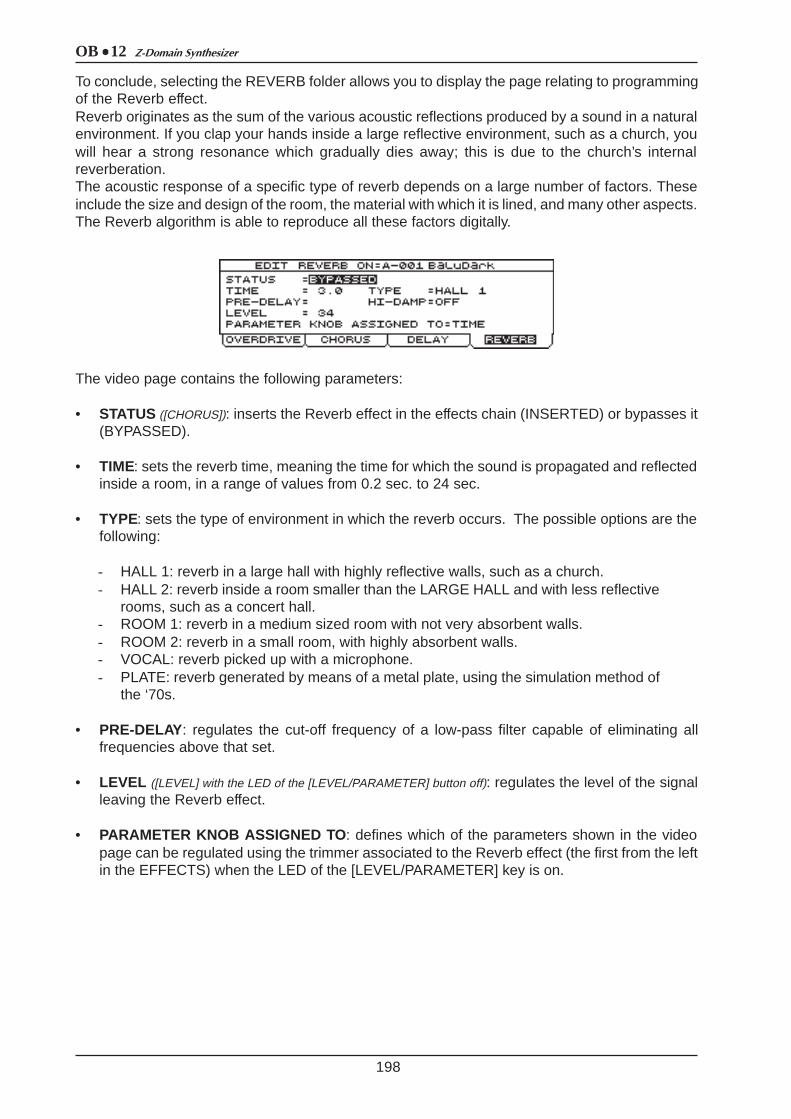
OB 12 Z-Domain Synthesizer
198
To conclude, selecting the REVERB folder allows you to display the page relating to programmingof the Reverb effect.Reverb originates as the sum of the various acoustic reflections produced by a sound in a naturalenvironment. If you clap your hands inside a large reflective environment, such as a church, youwill hear a strong resonance which gradually dies away; this is due to the church’s internalreverberation.The acoustic response of a specific type of reverb depends on a large number of factors. Theseinclude the size and design of the room, the material with which it is lined, and many other aspects.The Reverb algorithm is able to reproduce all these factors digitally.
The video page contains the following parameters:
• STATUS ([CHORUS]): inserts the Reverb effect in the effects chain (INSERTED) or bypasses it(BYPASSED).
• TIME: sets the reverb time, meaning the time for which the sound is propagated and reflectedinside a room, in a range of values from 0.2 sec. to 24 sec.
• TYPE: sets the type of environment in which the reverb occurs. The possible options are thefollowing:
- HALL 1: reverb in a large hall with highly reflective walls, such as a church.- HALL 2: reverb inside a room smaller than the LARGE HALL and with less reflective
rooms, such as a concert hall.- ROOM 1: reverb in a medium sized room with not very absorbent walls.- ROOM 2: reverb in a small room, with highly absorbent walls.- VOCAL: reverb picked up with a microphone.- PLATE: reverb generated by means of a metal plate, using the simulation method of
the ‘70s.
• PRE-DELAY : regulates the cut-off frequency of a low-pass filter capable of eliminating allfrequencies above that set.
• LEVEL ([LEVEL] with the LED of the [LEVEL/PARAMETER] button off): regulates the level of the signalleaving the Reverb effect.
• PARAMETER KNOB ASSIGNED TO : defines which of the parameters shown in the videopage can be regulated using the trimmer associated to the Reverb effect (the first from the leftin the EFFECTS) when the LED of the [LEVEL/PARAMETER] key is on.
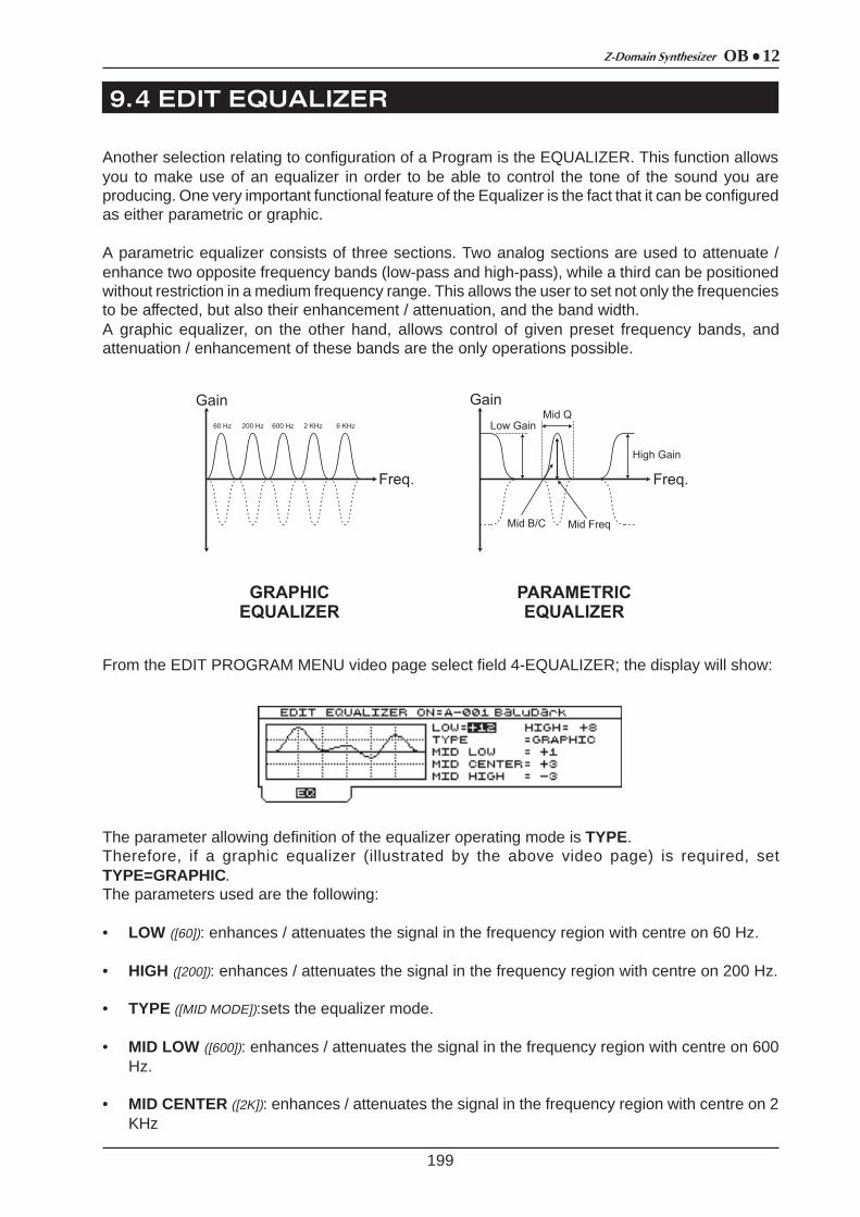
OB 12Z-Domain Synthesizer
9. 4 EDIT EQUALIZER
199
Another selection relating to configuration of a Program is the EQUALIZER. This function allowsyou to make use of an equalizer in order to be able to control the tone of the sound you areproducing. One very important functional feature of the Equalizer is the fact that it can be configuredas either parametric or graphic.
A parametric equalizer consists of three sections. Two analog sections are used to attenuate /enhance two opposite frequency bands (low-pass and high-pass), while a third can be positionedwithout restriction in a medium frequency range. This allows the user to set not only the frequenciesto be affected, but also their enhancement / attenuation, and the band width.A graphic equalizer, on the other hand, allows control of given preset frequency bands, andattenuation / enhancement of these bands are the only operations possible.
From the EDIT PROGRAM MENU video page select field 4-EQUALIZER; the display will show:
The parameter allowing definition of the equalizer operating mode is TYPE.Therefore, if a graphic equalizer (illustrated by the above video page) is required, setTYPE=GRAPHIC.The parameters used are the following:
• LOW ([60]): enhances / attenuates the signal in the frequency region with centre on 60 Hz.
• HIGH ([200]): enhances / attenuates the signal in the frequency region with centre on 200 Hz.
• TYPE ([MID MODE]):sets the equalizer mode.
• MID LOW ([600]): enhances / attenuates the signal in the frequency region with centre on 600Hz.
• MID CENTER ([2K]): enhances / attenuates the signal in the frequency region with centre on 2KHz

OB 12 Z-Domain Synthesizer
9.5 LINKS
200
• MID HIGH ([6K]): enhances / attenuates the signal in the frequency region with centre on 6KHz.
If these equalization parameters (and therefore not TYPE) are set at –12 you will obtain attenuationof the signal of -12 dB; conversely, setting them at +12 will give an enhancement of +12 dB. If theparameters are set at 0, the signals will be unaffected by the influence of the equalizer.
If you now wish to set the equalizer as parametric, set parameter TYPE=PARAM .
In this case, the parameters are the following:
• LOW ([LOW]): enhances / attenuates the signal in the frequency region with centre on 60 Hz.
• HIGH ([HIGH]): enhances / attenuates the signal with frequencies over 6 KHz.
• TYPE ([MID MODE]): sets the equalizer mode.
• MID FREQ. (Mid Frequency, [MID]): sets the region of frequencies, in the medium range, of thesignal to be enhanced / attenuated.
• MID B/C (Mid Boost/Cut [FREQ]): regulates the enhancement / attenuation of the area of frequenciesequal to that set with the MID FREQ parameter.
• MID Q ([Q]): regulates the band width of operation in the medium range specified with the MIDFREQ parameter.
If the LOW, MID B/C and HIGH parameters are set at –12 you will obtain attenuation of the signalof -12 dB; conversely, setting them at +12 will give an enhancement of +12 dB. If the parametersare set at 0, the signals will be unaffected by the influence of the equalizer.
The LINKS function allows the RATE parameter of LFO1 and of CHORUS effect and the DELAYTIME to be linked to the TEMPO parameter of the ARPEGGIO or the PHRASE RECORDER, andto the MIDI Clock message present on the MIDI [IN] port. All this is in order to guarantee perfectsynchronisation of the above sections or with a remote MIDI instrument.See also point 10.3 for further information concerning MIDI synchronisation.
N.B.: If the MIDI signal referred to above is not present on the MIDI [IN] port in case of Link to theMIDI Clock, the parameters linked to it will be set with the respective lowest value.
In order to provide information about the status of the parameters which may be linked, when thevideo pages relating to the parameters referred to above are displayed from the Programenvironment (therefore, in order to display the LFO1 Rate you will have to carry out a Swappingoperation), the display will show an “L” in square brackets against the parameters which havebeen linked.
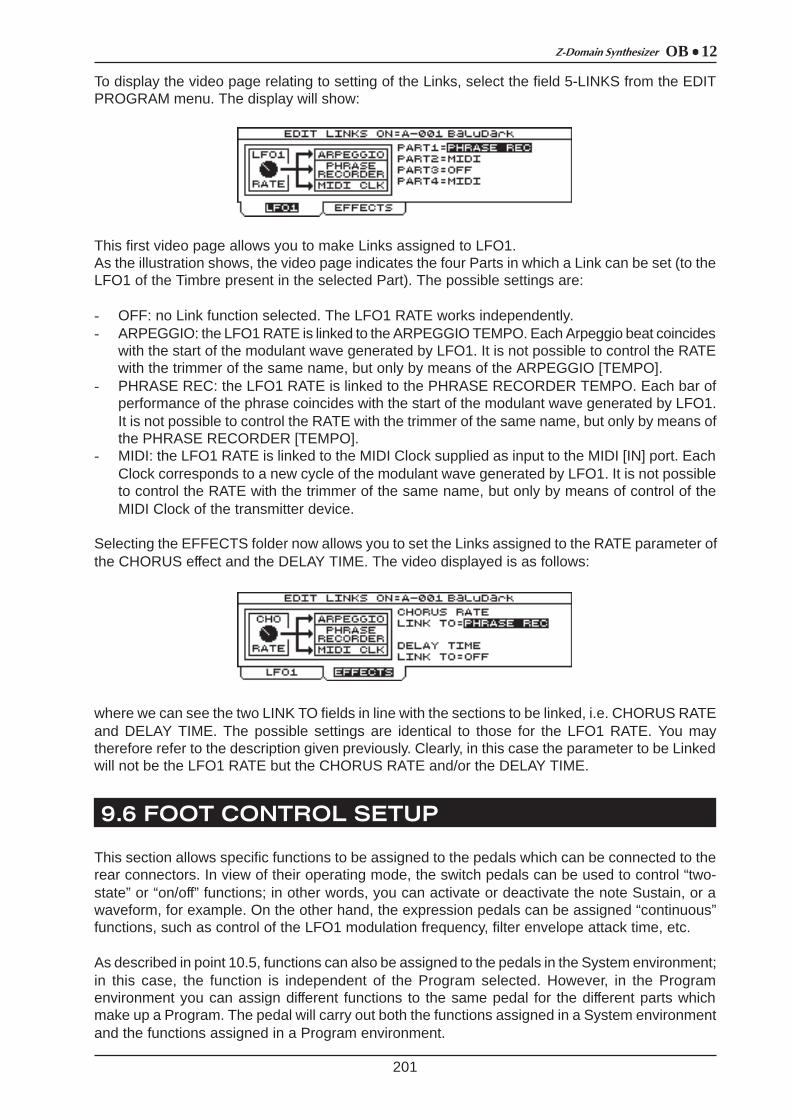
OB 12Z-Domain Synthesizer
9.6 FOOT CONTROL SETUP
201
To display the video page relating to setting of the Links, select the field 5-LINKS from the EDITPROGRAM menu. The display will show:
This first video page allows you to make Links assigned to LFO1.As the illustration shows, the video page indicates the four Parts in which a Link can be set (to theLFO1 of the Timbre present in the selected Part). The possible settings are:
- OFF: no Link function selected. The LFO1 RATE works independently.- ARPEGGIO: the LFO1 RATE is linked to the ARPEGGIO TEMPO. Each Arpeggio beat coincides
with the start of the modulant wave generated by LFO1. It is not possible to control the RATEwith the trimmer of the same name, but only by means of the ARPEGGIO [TEMPO].
- PHRASE REC: the LFO1 RATE is linked to the PHRASE RECORDER TEMPO. Each bar ofperformance of the phrase coincides with the start of the modulant wave generated by LFO1.It is not possible to control the RATE with the trimmer of the same name, but only by means ofthe PHRASE RECORDER [TEMPO].
- MIDI: the LFO1 RATE is linked to the MIDI Clock supplied as input to the MIDI [IN] port. EachClock corresponds to a new cycle of the modulant wave generated by LFO1. It is not possibleto control the RATE with the trimmer of the same name, but only by means of control of theMIDI Clock of the transmitter device.
Selecting the EFFECTS folder now allows you to set the Links assigned to the RATE parameter ofthe CHORUS effect and the DELAY TIME. The video displayed is as follows:
where we can see the two LINK TO fields in line with the sections to be linked, i.e. CHORUS RATEand DELAY TIME. The possible settings are identical to those for the LFO1 RATE. You maytherefore refer to the description given previously. Clearly, in this case the parameter to be Linkedwill not be the LFO1 RATE but the CHORUS RATE and/or the DELAY TIME.
This section allows specific functions to be assigned to the pedals which can be connected to therear connectors. In view of their operating mode, the switch pedals can be used to control “two-state” or “on/off” functions; in other words, you can activate or deactivate the note Sustain, or awaveform, for example. On the other hand, the expression pedals can be assigned “continuous”functions, such as control of the LFO1 modulation frequency, filter envelope attack time, etc.
As described in point 10.5, functions can also be assigned to the pedals in the System environment;in this case, the function is independent of the Program selected. However, in the Programenvironment you can assign different functions to the same pedal for the different parts whichmake up a Program. The pedal will carry out both the functions assigned in a System environmentand the functions assigned in a Program environment.

OB 12 Z-Domain Synthesizer
202
From the EDIT PROGRAM MENU video page, select field 5-FOOT CTRL. The display will show:
This video page allows a given function to be assigned to the foot-switch pedal connected to thePEDALS [SWITCH 1] connector.The parameters displayed are:
• PART: defines the Part to which the function specified with the FUNCTION parameter refers.When other Parts are selected, the function assigned to the previous Part remains in thememory.
• FUNCTION: assigns the function to the foot-switch pedal, for the Part specified with theparameter of the same name.
The parameters which can be controlled are the following:
The [F2] button allows you to select the SWITCH2 folder, and display the video page relating tothe second pedal connected to the PEDALS [SWITCH2] connector. Follow the instructions providedfor the settings of Switch1 for the Switch2 video page.By selecting the PEDAL1 folder you can now display the video page relating to the settings of theexpression pedal connected to the PEDALS [EXP.1] connector.
SELECTIONS FUNCTIONSCONTROLS ON
PANELSELECTIONS FUNCTIONS
CONTROLS ON PANEL
DISABLED no function applied AUTOPANit activates and disactivates the
Autopan function[AUTOPAN] of
AMPLIFIER
SUSTAINthe notes played after having pressed the pedal will remain hanging till it will be released
LFO1 WAVE it activates cyclically the 4 waves of LFO1
[WAVE SELECT] of LFO1
TIMBRE UPit activates the Timbre following the
one actually active in PartEncoder LFO2 WAVE
it activates cyclically the 4 waves of LFO2
[WAVE SELECT] of LFO2
TIMBRE DOWN it activates the Timbre previous to the one actually active in Part
Encoder PORTAMENTO it activates and disactivates the Portamento function
[PORTAMENTO] of KEYBOARD
OSC1 SAW in activates and disactivated the saw wave generated by OSC.1
[WAVE SELECT] of SAW of OSC.1 UNISON it activates and disactivates the
Unison function[UNISON] of KEYBOARD
OSC1 TRIANGin activates and disactivated the
triangular wave generated by OSC.1[WAVE SELECT] of TRIANGLE of OSC.1 MONO/POLY
it cyclically varies the keyboard mode: monophonic and polyphonic
[MONO] of KEYBOARD
OSC1 PULSEin activates and disactivated the
square wave generated by OSC.1[WAVE SELECT] of PULSE of OSC.1 LEGATO
in activates and disactivates the legato function
[LEGATO] of KEYBOARD
OSC2 SAWin activates and disactivated the saw
wave generated by OSC.2[WAVE SELECT] of
SAW di OSC.2 OSC 1 SHIFT it cyclically modifies OSC.1 tuning[OCT+] and [OCT-] of
KEYBOARD with [OSC SHIFT] on OSC1
OSC2 TRIANGin activates and disactivated the
triangular wave generated by OSC.2[WAVE SELECT] of TRIANGLE of OSC.2 OSC 2 SHIFT it cyclically modifies OSC.2 tuning
[OCT+] and [OCT-] of KEYBOARD with [OSC
SHIFT] on OSC2
OSC2 PULSEin activates and disactivated the
square wave generated by OSC.2[WAVE SELECT] of PULSE of OSC.2 VELOCITY
it activates and disactivates the Velocity
[VELOCITY] of KEYBOARD SENSE
OSC2 SYNCit activates and disactivated the
syncronisation between OSC.1 and OSC.2
[SYNC] of OSC.2 VEL TYPEit cyclically changes the Velocity
type
OSC2 KEYB T it activates and disactivated the Keyboard Tracking of OSC.2
[KBD TRACK] of OSC.2 AFTERTOUCH it activates and disactivates the
Aftertouch[AFTERTOUCH] of
KEYBOARD SENSE
FILTER ROUTit cyclically changes the connection
type of the two filters in FILTER section
[ROUTING] of FILTERS AFTERT TYPE it cyclically changes the Aftertouch
types
FLT 1 L/B/H cyclically type variation for FILTER1 [FILTER 1] of FILTERS PITCH BEND it activates and disactivates the
[PITCH] wheel
FLT 2 L/B/H cyclically type variation for FILTER2 [FILTER 2] of FILTERS MODULATIONit activates and disactivates the
[MODULATION] wheel

OB 12Z-Domain Synthesizer
203
containing the following parameters:
• PART: defines the Part to which the function specified with the FUNCTION parameter refers.When other Parts are selected, the function assigned to the previous Part remains in thememory.
• FUNCTION: assigns the function to the expression pedal, for the Part specified with theparameter of the same name.
• MIN and MAX: set the minimum and maximum values of the parameter controlled by thepedal.
The parameters which can be assigned to the expression pedal are the following:
SELECTIONSCONTROLLED PARAMETERS
CONTROLS ON PANEL
SELECTIONSCONTROLLED PARAMETERS
CONTROLS ON PANEL
DISABLED none OSC1 PUL.WDsquare wave pulse width generated by
OSC.1
[OSC CTRL] assigned to square wave of OSCILLATOR1
LFO1-FADE time for reach the max. level of LFO1 signal
[FADE] of LFO1] OSC1 FM modulation depth of OSC.2 on OSC.1
[FM] of OSCILLATOR1
LFO1-RATE LFO1 signal frequency [RATE] of LFO1 OSC1 LFO1DPmodulation depth of
LFO1 on OSC.1[LFO1 DEPTH] of OSCILLATOR1
BALANCE 1 balance between OSC.1 and OSC.2
[BALANCE 1] of OSC.COMMON OSC1PWMLFO1
pulse with modulation depth of LFO1 on
OSC.1
[PWM DEPTH] assigned to LFO1 of
OSCILLATOR1
BALANCE 2balance between
OSC.1+OSC.2 and RING MODULATOR
[BALANCE 2] of OSC.COMMON OSC1PWMLFO2
pulse with modulation depth of LFO2 on
OSC.1
[PWM DEPTH] assigned to LFO2 of
OSCILLATOR1
BALANCE 3
balance between OSC.1+OSC.2+RING
MODULATOR and NOISE
[BALANCE 3] of OSC.COMMON OSC1PWMEG
pulse width modulation depth of EG on OSC.1
[PWM DEPTH] assigned to EG of OSCILLATOR1
OSC.COM.ATTattack time of the
OSC.1 and OSC.2 envelope
[ATTACK] of OSC.COMON OSC2 SAW LV saw wave level
generated by OSC.2
[WAVE MIX] of the saw wave of OSCILLATOR
2
OSC.COM.DECdecay time of the
OSC.1 and OSC.2 [DECAY] of
OSC.COMMON OSC2 TRI.LVtriangle wave level
generated by OSC.2
[WAVE MIX] of the triangle wave of OSCILLATOR2
OSC1COM.ENV OSC.1 envelope depth[ENV DEPTH] on
OSC.1 of OSC.COMMON
OSC2 PUL.LVsquare wave level
generated by OSC.2
[WAVE MIX] of the square wave of OSCILLATOR2
OSC2COM.ENV OSC.2 envelope depth[ENV DEPTH] on
OSC.2 of OSC.COMMON
OSC2 PUL.WDsquare wave pulse width generated by
OSC.2
[OSC CTRL] assigned to square wave of OSCILLATOR2
OSC1 SAW LVsaw wave level
generated by OSC.1
[WAVE MIX] of the saw wave of OSCILLATOR
1OSC2 LFO1DP
modulation depth of LFO1 on OSC.2
[LFO1 DEPTH] of OSCILLATOR2
OSC1 TRI.LVtriangular wave level generated by OSC.1
[WAVE MIX] of the triangular wave of OSCILLATOR1
OSC2PWMLFO1pulse with modulation
depth of LFO1 on OSC.2
[PWM DEPTH] assegnato a LFO1 di
OSCILLATOR2
OSC1 PUL.LV square wave level generated by OSC.1
[WAVE MIX] of the square wave of OSCILLATOR1
OSC2PWMLFO2pulse with modulation
depth of LFO2 on OSC.2
[PWM DEPTH] assigned to LFO2 of
OSCILLATOR2
OSC1 SAW SPsaw wave modification generated by OSC.1
[WAVE CTRL] assigned to saw wave
of OSCILLATOR1 OSC2PWMEG
pulse width modulation depth of EG on OSC.2
[PWM DEPTH] assigned to EG of OSCILLATOR2
OSC1 TRI.WRtriangle wave
modification generated by OSC.1
[WAVE CTRL] assigned to triangle
wave of OSCILLATOR1
FILT.FREQ.cut-off frequency of
FILTERS[FREQUENCY] of
FILTERS

OB 12 Z-Domain Synthesizer
9.7 ARPEGGIO SETTINGS
204
By selecting the PEDAL2 folder you can assign the function of choice to the pedal connected tothe rear PEDAL [EXP.2] connector. The video page will be identical to that relating to the PEDAL1setting.
The ARPEGGIO function allows arpeggios to be performed by playing a chord on the keyboard orpressing just one note and creating octave arpeggios on it.
The HOLD function (activated using the button of the same name in this section) allows you to playarpeggios even after the keyboard notes have been released. Notes played subsequently willreplace the previous ones with the arpeggio mode active.You can therefore use regular arpeggios, by selecting the beat required, or irregular arpeggios, forwhich there are a choice of Patterns.
This section of the Program environment allows you to set the modes, the range in octaves andthe tempo of the arpeggio, and the keyboard section and Parts affected by the function.
This section is independent of the PART SETTINGS: the arpeggio notes will be performed with theTimbres present in the Parts enabled for the function.
From the EDIT PROGRAM MENU select field 6-ARPEGGIO. The display will show the first videopage relating to the settings of this function:
SELECTIONSCONTROLLED PARAMETERS
CONTROLS ON PANEL
SELECTIONSCONTROLLED PARAMETERS
CONTROLS ON PANEL
FILT.RES. resonance of FILTERS[RESONANCE] of
FILTERS AMPL.REL.release time of the
AMPLIFIER envelope[RELEASE] of AMPLIFIER
FILT.ATTACKattack time of the
FILTERS envelope[ATTACK] of FILTERS AMPL.AMOUNT Timbre level
[AMOUNT] of AMPLIFIER
FILT.DECAYdecay time of the
FILTERS envelope[DECAY] of FILTERS AMPL.LFO1DP
modulation depth of LFO1 on AMPLIFIER
[LFO1 DEPTH] of AMPLIFIER
FILT.SUST.sustain level of the FILTERS envelope
[SUSTAIN] of FILTERS LFO2 RATE LFO2 signal frequency [RATE] of LFO2
FILT.REL. release time of the FILTERS envelope
[RELEASE] of FILTERS LFO2 DP.OS1 modulation depth of
LFO2 on OSC.1[MODULATION]
FILT.ENV.DPFILTERS envelope
depth[ENV DEPTH] of
FILTERS LFO2 DP.OS2modulation depth of
LFO2 on OSC.2[MODULATION]
FILT.LFO1DPmodulation depth of
LFO1 on OSC.1[LFO1 DEPTH] of
FILTERS LFO2 DP.FLTmodulation depth of LFO2 on FILTERS
[MODULATION]
AMPL.ATTACKattack time of the
AMPLIFIER envelope[ATTACK] of AMPLIFIER LFO2 DP.AMP
modulation depth of LFO2 on AMPLIFIER
[MODULATION]
AMPL.DECAY decay time of the AMPLIFIER envelope
[DECAY] of AMPLIFIER PORTAM.TIME Portamento time
[TIME] of PORTAMENTO
AMPL.SUST. sustain level of the AMPLIFIER envelope
[SUSTAIN] of AMPLIFIER
the parameters this video page contains are the following:
• STATUS (Arpeggio Status, [ON/OFF] in the ARPEGGIO section): activates (ON) or disables (OFF) theArpeggio function.

OB 12Z-Domain Synthesizer
205
• MODE ([MODE]): sets the arpeggio mode as follows:
- UP: the arpeggio is performed cyclically from the lowest to the highest note as shown in thediagram:
- DOWN: the arpeggio is performed cyclically from the highest to the lowest note as shown inthe diagram:
- UP & DOWN (UP and DOWN LEDs on): the arpeggio is performed cyclically from the lowestto the highest note and vice-versa, as shown in the diagram:
- RANDOM (RND): the arpeggio notes will be played at random, as shown in the diagram:
• RANGE ([RANGE]): sets the range of the arpeggio in octaves. The possible settings are:
- +0 oct : arpeggio range one octave.- +1 oct. : arpeggio range one octave above the one played.- +2 oct. : arpeggio range two octaves above the one played.- +3 oct. : arpeggio range three octaves above the one played.
• TEMPO ([TEMPO] or [TAP TEMPO] of the ARPEGGIO section): sets the arpeggio time in a range of25÷250 BPM. If there are MIDI Clock messages on the MIDI [IN] port and its assignment to thisfunction has been enabled (see point 10.3), the value of this parameter will be that specified bythe MIDI message.
When button [F2] is pressed, the display will show the video page relating to assignment of akeyboard section and Parts to the arpeggio.
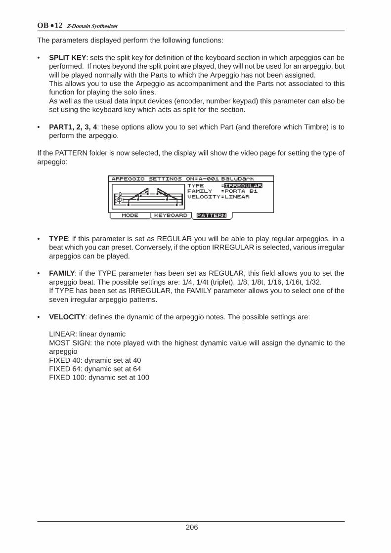
OB 12 Z-Domain Synthesizer
206
The parameters displayed perform the following functions:
• SPLIT KEY: sets the split key for definition of the keyboard section in which arpeggios can beperformed. If notes beyond the split point are played, they will not be used for an arpeggio, butwill be played normally with the Parts to which the Arpeggio has not been assigned.This allows you to use the Arpeggio as accompaniment and the Parts not associated to thisfunction for playing the solo lines.As well as the usual data input devices (encoder, number keypad) this parameter can also beset using the keyboard key which acts as split for the section.
• PART1, 2, 3, 4: these options allow you to set which Part (and therefore which Timbre) is toperform the arpeggio.
If the PATTERN folder is now selected, the display will show the video page for setting the type ofarpeggio:
• TYPE: if this parameter is set as REGULAR you will be able to play regular arpeggios, in abeat which you can preset. Conversely, if the option IRREGULAR is selected, various irregulararpeggios can be played.
• FAMILY: if the TYPE parameter has been set as REGULAR, this field allows you to set thearpeggio beat. The possible settings are: 1/4, 1/4t (triplet), 1/8, 1/8t, 1/16, 1/16t, 1/32.If TYPE has been set as IRREGULAR, the FAMILY parameter allows you to select one of theseven irregular arpeggio patterns.
• VELOCITY: defines the dynamic of the arpeggio notes. The possible settings are:
LINEAR: linear dynamicMOST SIGN: the note played with the highest dynamic value will assign the dynamic to thearpeggioFIXED 40: dynamic set at 40FIXED 64: dynamic set at 64FIXED 100: dynamic set at 100

OB 12Z-Domain Synthesizer
9.8 PHRASE RECORDER
207
The PHRASE RECORDER allows musical phrases to be recorded and repeated by simply pressinga keyboard key, which from now on we will call the pilot key.The musical phrase selected will thus be repeated until the key mentioned above is released. If theHOLD function is enabled it will not be necessary to keep the key pressed since the musicalphrase will be played even after its release. If another pilot key assigned to another musical phraseis pressed, this phrase will replace the previous one in the playback function. To activate / deactivatethe Hold function, press the button of the same name in the PHRASE section of the front panel.
One very important feature of the Phrase Recorder is that while a given musical phrase is beingrepeated with the Hold function active, you will be able to vary the parameters relating to generationof the sound, to obtain continuous variation of the timbre with which it is performed. What’s more,once you have set the correct keyboard split point and the Parts assigned to the Phrase Recorder,you will be able to play without restriction in the keyboard zone not enabled for this function, whilethe phrase is being repeated.
The internal memory enabled for the recording of phrases is divided into four SETS, one of whichcan be assigned to each Program. Each Set can be viewed as a memory bank in which therecorded phrases can be saved. Therefore, a key can be configured as the pilot key of four phrases,each saved in one Set. If the phrases are then placed in the desired Sets, you will be able to usegiven groups of phrases depending on the Program active at the time.In theory, the Phrase Recorder can contain up to 196 musical phrases; in fact, the memoryassociated to it can contain 16000 notes. Thanks to the MEMORY STATISTIC section in theSYSTEM environment (see point 10.8) you can be constantly informed about the amount of memoryavailable.
The PHRASE RECORDER function is divided into two programming sections.One can be recalled from the EDIT PROGRAM MENU and is called PHRASE RECORDERSETTINGS; this allows you to enable or disable the function and Set of phrases associated to theProgram active at that moment, regulate the metronome tempo, and enable a keyboard zone andthe Program Parts (and therefore the timbres) for performance of the musical phrase.Another, called RECORD PHRASE, can be recalled by pressing the [REC] button in the PHRASEsection of the front panel, and enables the recording or monitoring of a given phrase.
PHRASE RECORDER SETTINGS
From the EDIT PROGRAM MENU, select field 7-PHRASE REC.; the display will show the videopage relating to the main settings of the Phrase Recorder:
in which the following parameters can be set:
• STATUS ([ON/OFF] of the PHRASE section): enables (ON) or disables (OFF) the Phrase Recorder.
• SET: sets the Set of phrases active when the Program is recalled.
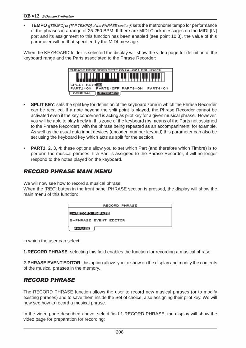
OB 12 Z-Domain Synthesizer
208
• TEMPO ([TEMPO] or [TAP TEMPO] of the PHRASE section): sets the metronome tempo for performanceof the phrases in a range of 25-250 BPM. If there are MIDI Clock messages on the MIDI [IN]port and its assignment to this function has been enabled (see point 10.3), the value of thisparameter will be that specified by the MIDI message.
When the KEYBOARD folder is selected the display will show the video page for definition of thekeyboard range and the Parts associated to the Phrase Recorder:
• SPLIT KEY: sets the split key for definition of the keyboard zone in which the Phrase Recordercan be recalled. If a note beyond the split point is played, the Phrase Recorder cannot beactivated even if the key concerned is acting as pilot key for a given musical phrase. However,you will be able to play freely in this zone of the keyboard (by means of the Parts not assignedto the Phrase Recorder), with the phrase being repeated as an accompaniment, for example.As well as the usual data input devices (encoder, number keypad) this parameter can also beset using the keyboard key which acts as split for the section.
• PART1, 2, 3, 4: these options allow you to set which Part (and therefore which Timbre) is toperform the musical phrases. If a Part is assigned to the Phrase Recorder, it will no longerrespond to the notes played on the keyboard.
RECORD PHRASE MAIN MENU
We will now see how to record a musical phrase.When the [REC] button in the front panel PHRASE section is pressed, the display will show themain menu of this function:
in which the user can select:
1-RECORD PHRASE: selecting this field enables the function for recording a musical phrase.
2-PHRASE EVENT EDITOR: this option allows you to show on the display and modify the contentsof the musical phrases in the memory.
RECORD PHRASE
The RECORD PHRASE function allows the user to record new musical phrases (or to modifyexisting phrases) and to save them inside the Set of choice, also assigning their pilot key. We willnow see how to record a musical phrase.
In the video page described above, select field 1-RECORD PHRASE; the display will show thevideo page for preparation for recording:

OB 12Z-Domain Synthesizer
209
containing the following programming parameters:
• SET: establishes the Set in which the musical phrase to be recorded will be saved, or whichcontains the phrase to be modified.
• TRIGGER NOTE: defines the pilot key, meaning the keyboard key enabled to start the musicalphrase. The value can also be entered by pressing the keyboard key of choice. In case ofover-recording or modifications of songs already in the memory, this parameter can also beused to recall a phrase once the relative pilot key is known. This allows display of the relativerecording parameters.
• TEMPO ([TEMPO or [TAP TEMPO] of the PHRASE section): regulates the metronome tempo withwhich the Phrase is to be recorded in a range of 25÷250 BPM.
• MEASURE: sets the number of bars (measures) of which the phrase to be recorded consists.If the preset number of bars is exceeded, the data which follow (the notes played after the lastbar) will be recorded in a new loop, and will overwrite or replace (see REC MODE parameter)the notes played previously. Musical phrases with a maximum length of 32 bars can be recorded.
• TIME SIGN. (Time Signature): sets the time signature of the recording to be made. The valuesavailable are: 2/4, 3/4, 4/4, 5/4, 3/8, 5/8, 6/8, 7/8, 9/8, 12/8.
• REC MODE: sets the type of recording. If OVERDUB is selected, the data are over-recorded,so each new note will be added those already present (recorded in a previous session or loop).If the parameter is set as REPLACE, each new datum will replace those already present. If nonew events are present, the data recorded in previous sessions or loops will be retained.

OB 12 Z-Domain Synthesizer
210
• LAYER STAT. (Layer Status): if this parameter is set as PROGRAM, during recording you canplay (but not record) the phrase bearing in mind the Program settings (Part, Split / Layer,Effects, etc...). If TMB-SOLO is selected, the phrase will be played with the Timbre soundscurrent at that moment.
• METR.STATUS (Metronome Status): if this parameter is set as ON, the metronome will be audiblethroughout the recording phase. If PREC is selected, the metronome will only be heard in thePrecount phase, i.e. the bar inserted by the instrument before recording starts. Lastly, withOFF selected the metronome will be disabled.
• METR.LEVEL (Metronome Level): regulates the metronome level.
You can press button [F3] to select the CLEAR function to delete the contents of the Phrasecurrently selected (assigned to the key indicated by the TRIGGER NOTE parameter and presentin the set defined by the PHRASE SET field). The display will then request confirmation to proceedby means of the following video page:
As the display indicates, if the [ESC] button is pressed the procedure will be aborted, while pressing[ENTER] confirms it. In this case the display will inform the user that the data in the Phrase arebeing deleted:
If the GO! function is selected using the [F4] button, the recording procedure will be started. Thedisplay will show:
The START command can now be selected using the [F2] button to start recording:
The CURRENT MEASURE parameter shows the numbers of the bars as they pass ((useful duringover-recording to allow optimum placing of any added notes), while the TEMPO field indicates themetronome tempo for the recording.The screen also contains the STOP ([F2]) command for stopping the recording and CLEAR ([F3])for deleting the data present when the key itself is pressed.If RESET (button [F1]) is selected, the recording will be returned to bar 1.1.
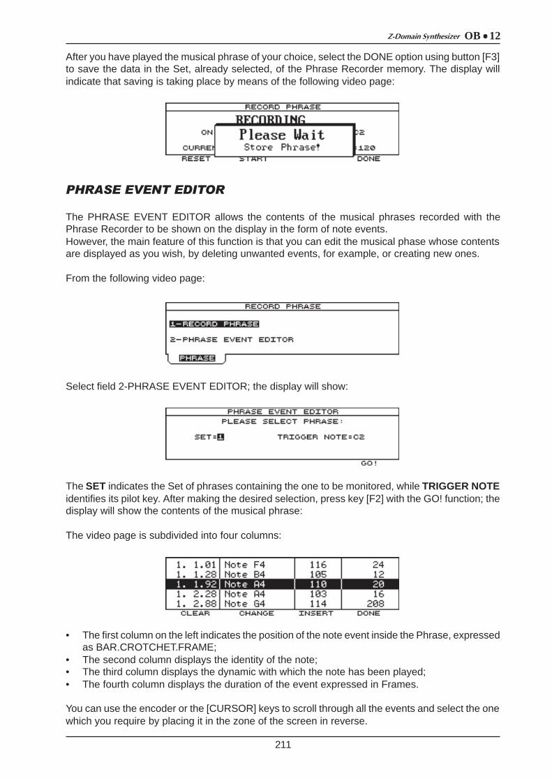
OB 12Z-Domain Synthesizer
211
After you have played the musical phrase of your choice, select the DONE option using button [F3]to save the data in the Set, already selected, of the Phrase Recorder memory. The display willindicate that saving is taking place by means of the following video page:
PHRASE EVENT EDITOR
The PHRASE EVENT EDITOR allows the contents of the musical phrases recorded with thePhrase Recorder to be shown on the display in the form of note events.However, the main feature of this function is that you can edit the musical phase whose contentsare displayed as you wish, by deleting unwanted events, for example, or creating new ones.
From the following video page:
Select field 2-PHRASE EVENT EDITOR; the display will show:
The SET indicates the Set of phrases containing the one to be monitored, while TRIGGER NOTEidentifies its pilot key. After making the desired selection, press key [F2] with the GO! function; thedisplay will show the contents of the musical phrase:
The video page is subdivided into four columns:
• The first column on the left indicates the position of the note event inside the Phrase, expressedas BAR.CROTCHET.FRAME;
• The second column displays the identity of the note;• The third column displays the dynamic with which the note has been played;• The fourth column displays the duration of the event expressed in Frames.
You can use the encoder or the [CURSOR] keys to scroll through all the events and select the onewhich you require by placing it in the zone of the screen in reverse.
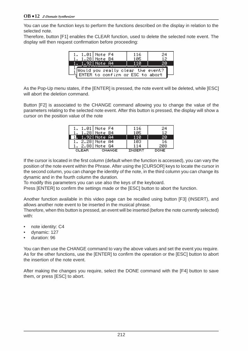
OB 12 Z-Domain Synthesizer
212
You can use the function keys to perform the functions described on the display in relation to theselected note.Therefore, button [F1] enables the CLEAR function, used to delete the selected note event. Thedisplay will then request confirmation before proceeding:
As the Pop-Up menu states, if the [ENTER] is pressed, the note event will be deleted, while [ESC]will abort the deletion command.
Button [F2] is associated to the CHANGE command allowing you to change the value of theparameters relating to the selected note event. After this button is pressed, the display will show acursor on the position value of the note
If the cursor is located in the first column (default when the function is accessed), you can vary theposition of the note event within the Phrase. After using the [CURSOR] keys to locate the cursor inthe second column, you can change the identity of the note, in the third column you can change itsdynamic and in the fourth column the duration.To modify this parameters you can use also the keys of the keyboard.Press [ENTER] to confirm the settings made or the [ESC] button to abort the function.
Another function available in this video page can be recalled using button [F3] (INSERT), andallows another note event to be inserted in the musical phrase.Therefore, when this button is pressed, an event will be inserted (before the note currently selected)with:
• note identity: C4• dynamic: 127• duration: 96
You can then use the CHANGE command to vary the above values and set the event you require.As for the other functions, use the [ENTER] to confirm the operation or the [ESC] button to abortthe insertion of the note event.
After making the changes you require, select the DONE command with the [F4] button to savethem, or press [ESC] to abort.
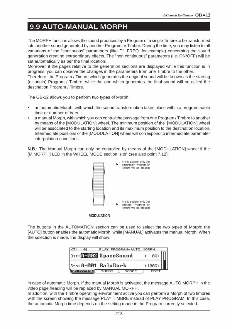
OB 12Z-Domain Synthesizer
9.9 AUTO-MANUAL MORPH
213
The MORPH function allows the sound produced by a Program or a single Timbre to be transformedinto another sound generated by another Program or Timbre. During the time, you may listen to allvariarions of the “continuous” parameters (like F.1 FREQ. for example) concerning the soundgeneration creating extraordinary effects. The “non continuous” parameters (i.e. ON/OFF) will beset automatically as per the final location.Moreover, if the pages relative to the generation sections are displayed while this function is inprogress, you can observe the changes in the parameters from one Timbre to the other.Therefore, the Program / Timbre which generates the original sound will be known as the starting(or origin) Program / Timbre, while the one which generates the final sound will be called thedestination Program / Timbre.
The OB-12 allows you to perform two types of Morph:
• an automatic Morph, with which the sound transformation takes place within a programmabletime or number of bars.
• a manual Morph, with which you can control the passage from one Program / Timbre to anotherby means of the [MODULATION] wheel. The minimum position of the [MODULATION] wheelwill be associated to the starting location and its maximum position to the destination location.Intermediate positions of the [MODULATION] wheel will correspond to intermediate parameterinterpolation conditions.
N.B.: The Manual Morph can only be controlled by means of the [MODULATION] wheel if the[M.MORPH] LED in the WHEEL MODE section is on (see also point 7.12).
The buttons in the AUTOMATION section can be used to select the two types of Morph: the[AUTO] button enables the automatic Morph, while [MANUAL] activates the manual Morph. Whenthe selection is made, the display will show:
in case of automatic Morph. If the manual Morph is activated, the message AUTO MORPH in thevideo page heading will be replaced by MANUAL MORPH.In addition, with the Timbre operating environment active you can perform a Morph of two timbreswith the screen showing the message PLAY TIMBRE instead of PLAY PROGRAM. In this case,the automatic Morph time depends on the setting made in the Program currently selected.
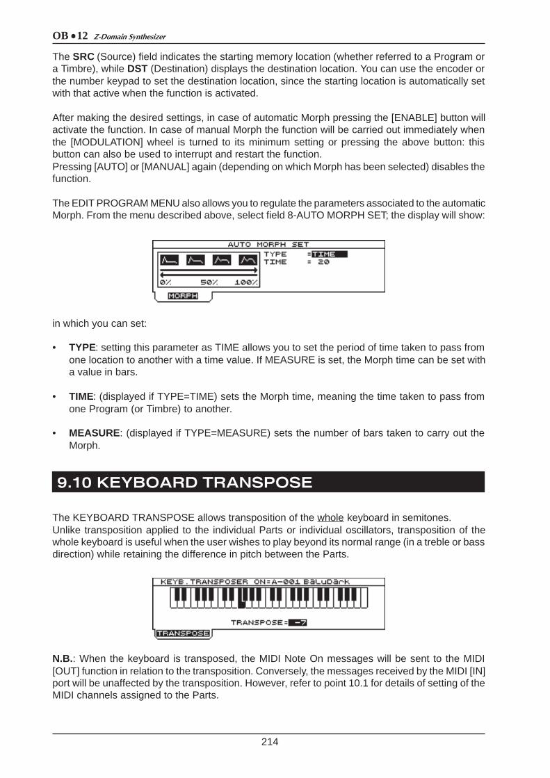
OB 12 Z-Domain Synthesizer
9.10 KEYBOARD TRANSPOSE
214
The SRC (Source) field indicates the starting memory location (whether referred to a Program ora Timbre), while DST (Destination) displays the destination location. You can use the encoder orthe number keypad to set the destination location, since the starting location is automatically setwith that active when the function is activated.
After making the desired settings, in case of automatic Morph pressing the [ENABLE] button willactivate the function. In case of manual Morph the function will be carried out immediately whenthe [MODULATION] wheel is turned to its minimum setting or pressing the above button: thisbutton can also be used to interrupt and restart the function.Pressing [AUTO] or [MANUAL] again (depending on which Morph has been selected) disables thefunction.
The EDIT PROGRAM MENU also allows you to regulate the parameters associated to the automaticMorph. From the menu described above, select field 8-AUTO MORPH SET; the display will show:
in which you can set:
• TYPE: setting this parameter as TIME allows you to set the period of time taken to pass fromone location to another with a time value. If MEASURE is set, the Morph time can be set witha value in bars.
• TIME: (displayed if TYPE=TIME) sets the Morph time, meaning the time taken to pass fromone Program (or Timbre) to another.
• MEASURE: (displayed if TYPE=MEASURE) sets the number of bars taken to carry out theMorph.
The KEYBOARD TRANSPOSE allows transposition of the whole keyboard in semitones.Unlike transposition applied to the individual Parts or individual oscillators, transposition of thewhole keyboard is useful when the user wishes to play beyond its normal range (in a treble or bassdirection) while retaining the difference in pitch between the Parts.
N.B.: When the keyboard is transposed, the MIDI Note On messages will be sent to the MIDI[OUT] function in relation to the transposition. Conversely, the messages received by the MIDI [IN]port will be unaffected by the transposition. However, refer to point 10.1 for details of setting of theMIDI channels assigned to the Parts.
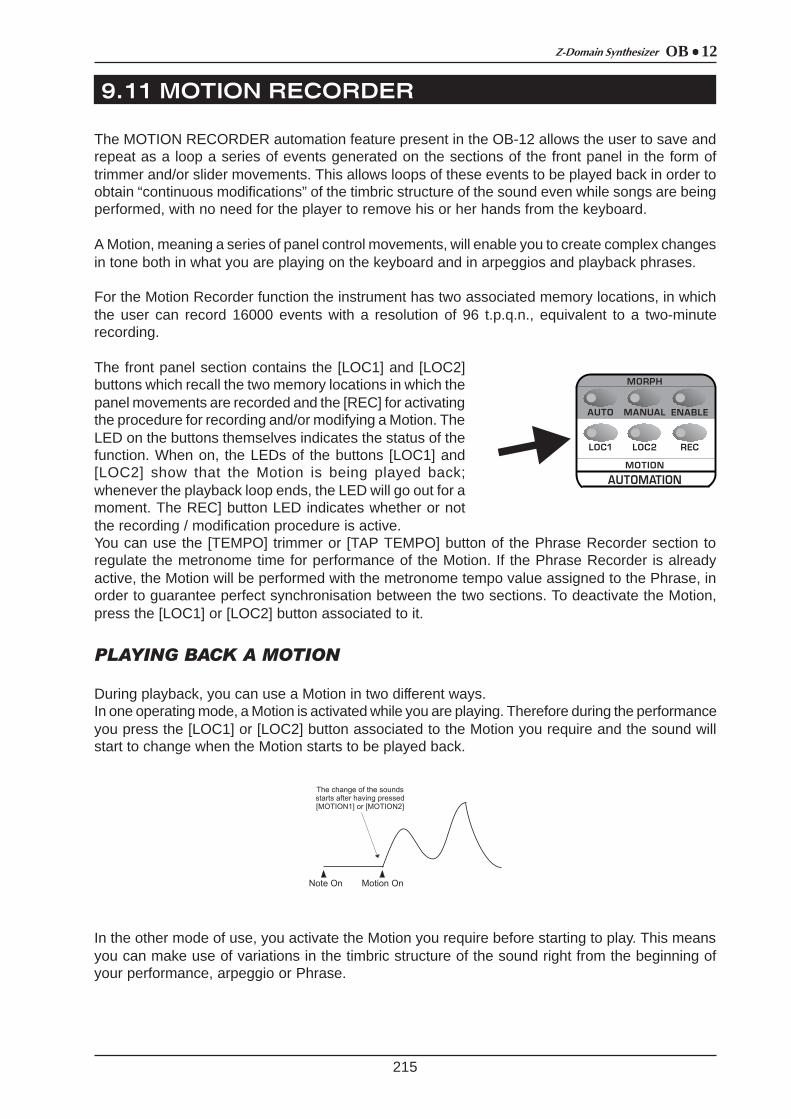
OB 12Z-Domain Synthesizer
9. 11 MOTION RECORDER
215
The MOTION RECORDER automation feature present in the OB-12 allows the user to save andrepeat as a loop a series of events generated on the sections of the front panel in the form oftrimmer and/or slider movements. This allows loops of these events to be played back in order toobtain “continuous modifications” of the timbric structure of the sound even while songs are beingperformed, with no need for the player to remove his or her hands from the keyboard.
A Motion, meaning a series of panel control movements, will enable you to create complex changesin tone both in what you are playing on the keyboard and in arpeggios and playback phrases.
For the Motion Recorder function the instrument has two associated memory locations, in whichthe user can record 16000 events with a resolution of 96 t.p.q.n., equivalent to a two-minuterecording.
The front panel section contains the [LOC1] and [LOC2]buttons which recall the two memory locations in which thepanel movements are recorded and the [REC] for activatingthe procedure for recording and/or modifying a Motion. TheLED on the buttons themselves indicates the status of thefunction. When on, the LEDs of the buttons [LOC1] and[LOC2] show that the Motion is being played back;whenever the playback loop ends, the LED will go out for amoment. The REC] button LED indicates whether or notthe recording / modification procedure is active.You can use the [TEMPO] trimmer or [TAP TEMPO] button of the Phrase Recorder section toregulate the metronome time for performance of the Motion. If the Phrase Recorder is alreadyactive, the Motion will be performed with the metronome tempo value assigned to the Phrase, inorder to guarantee perfect synchronisation between the two sections. To deactivate the Motion,press the [LOC1] or [LOC2] button associated to it.
PLAYING BACK A MOTION
During playback, you can use a Motion in two different ways.In one operating mode, a Motion is activated while you are playing. Therefore during the performanceyou press the [LOC1] or [LOC2] button associated to the Motion you require and the sound willstart to change when the Motion starts to be played back.
In the other mode of use, you activate the Motion you require before starting to play. This meansyou can make use of variations in the timbric structure of the sound right from the beginning ofyour performance, arpeggio or Phrase.
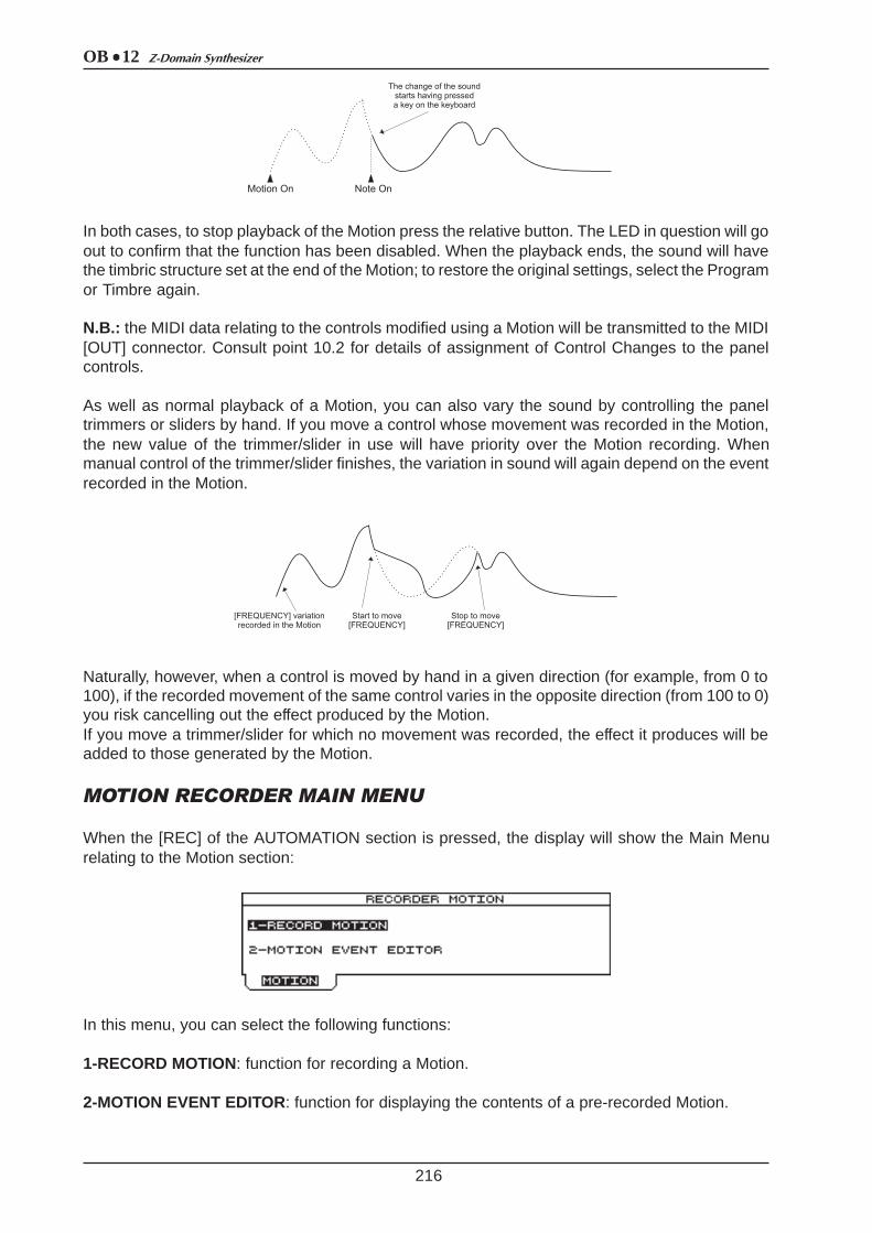
OB 12 Z-Domain Synthesizer
216
In both cases, to stop playback of the Motion press the relative button. The LED in question will goout to confirm that the function has been disabled. When the playback ends, the sound will havethe timbric structure set at the end of the Motion; to restore the original settings, select the Programor Timbre again.
N.B.: the MIDI data relating to the controls modified using a Motion will be transmitted to the MIDI[OUT] connector. Consult point 10.2 for details of assignment of Control Changes to the panelcontrols.
As well as normal playback of a Motion, you can also vary the sound by controlling the paneltrimmers or sliders by hand. If you move a control whose movement was recorded in the Motion,the new value of the trimmer/slider in use will have priority over the Motion recording. Whenmanual control of the trimmer/slider finishes, the variation in sound will again depend on the eventrecorded in the Motion.
Naturally, however, when a control is moved by hand in a given direction (for example, from 0 to100), if the recorded movement of the same control varies in the opposite direction (from 100 to 0)you risk cancelling out the effect produced by the Motion.If you move a trimmer/slider for which no movement was recorded, the effect it produces will beadded to those generated by the Motion.
MOTION RECORDER MAIN MENU
When the [REC] of the AUTOMATION section is pressed, the display will show the Main Menurelating to the Motion section:
In this menu, you can select the following functions:
1-RECORD MOTION: function for recording a Motion.
2-MOTION EVENT EDITOR: function for displaying the contents of a pre-recorded Motion.
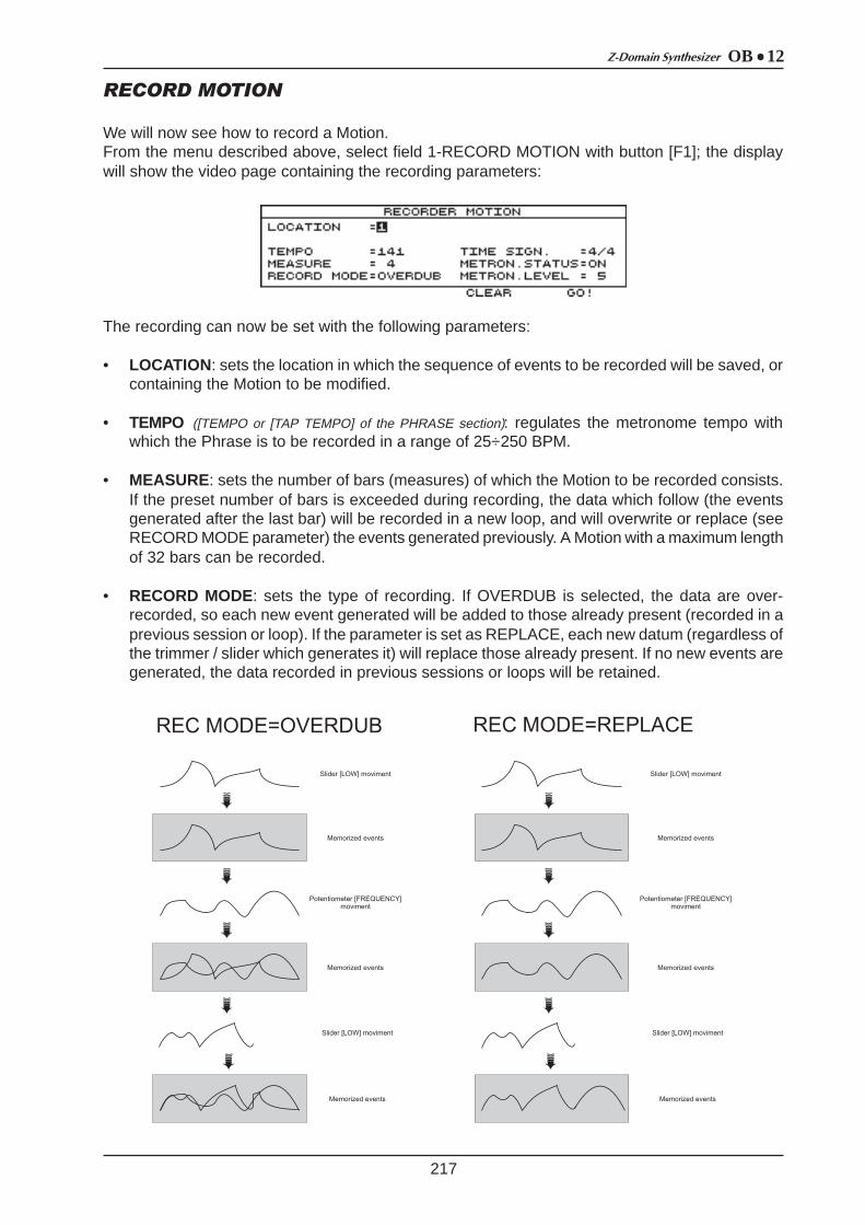
OB 12Z-Domain Synthesizer
217
RECORD MOTION
We will now see how to record a Motion.From the menu described above, select field 1-RECORD MOTION with button [F1]; the displaywill show the video page containing the recording parameters:
The recording can now be set with the following parameters:
• LOCATION: sets the location in which the sequence of events to be recorded will be saved, orcontaining the Motion to be modified.
• TEMPO ([TEMPO or [TAP TEMPO] of the PHRASE section): regulates the metronome tempo withwhich the Phrase is to be recorded in a range of 25÷250 BPM.
• MEASURE: sets the number of bars (measures) of which the Motion to be recorded consists.If the preset number of bars is exceeded during recording, the data which follow (the eventsgenerated after the last bar) will be recorded in a new loop, and will overwrite or replace (seeRECORD MODE parameter) the events generated previously. A Motion with a maximum lengthof 32 bars can be recorded.
• RECORD MODE: sets the type of recording. If OVERDUB is selected, the data are over-recorded, so each new event generated will be added to those already present (recorded in aprevious session or loop). If the parameter is set as REPLACE, each new datum (regardless ofthe trimmer / slider which generates it) will replace those already present. If no new events aregenerated, the data recorded in previous sessions or loops will be retained.
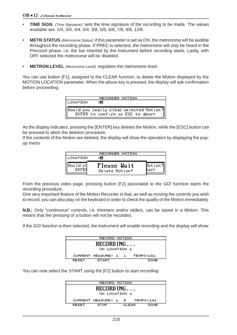
OB 12 Z-Domain Synthesizer
218
• TIME SIGN. (Time Signature): sets the time signature of the recording to be made. The valuesavailable are: 2/4, 3/4, 4/4, 5/4, 3/8, 5/8, 6/8, 7/8, 9/8, 12/8.
• METR.STATUS (Metronome Status): if this parameter is set as ON, the metronome will be audiblethroughout the recording phase. If PREC is selected, the metronome will only be heard in thePrecount phase, i.e. the bar inserted by the instrument before recording starts. Lastly, withOFF selected the metronome will be disabled.
• METRON.LEVEL (Metronome Level): regulates the metronome level.
You can use button [F1], assigned to the CLEAR function, to delete the Motion displayed by theMOTION LOCATION parameter. When the above key is pressed, the display will ask confirmationbefore proceeding:
As the display indicates, pressing the [ENTER] key deletes the Motion, while the [ESC] button canbe pressed to abort the deletion procedure.If the contents of the Motion are deleted, the display will show the operation by displaying the pop-up menu:
From the previous video page, pressing button [F2] associated to the GO! function starts therecording procedure.One very important feature of the Motion Recorder is that, as well as moving the controls you wishto record, you can also play on the keyboard in order to check the quality of the Motion immediately.
N.B.: Only “continuous” controls, i.e. trimmers and/or sliders, can be saved in a Motion. Thismeans that the pressing of a button will not be recorded.
If the GO! function is then selected, the instrument will enable recording and the display will show:
You can now select the START using the [F2] button to start recording:
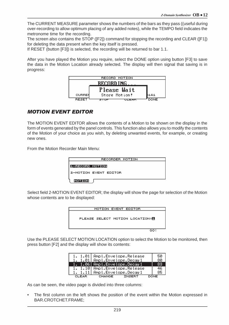
OB 12Z-Domain Synthesizer
219
The CURRENT MEASURE parameter shows the numbers of the bars as they pass ((useful duringover-recording to allow optimum placing of any added notes), while the TEMPO field indicates themetronome time for the recording.The screen also contains the STOP ([F2]) command for stopping the recording and CLEAR ([F1])for deleting the data present when the key itself is pressed.If RESET (button [F3]) is selected, the recording will be returned to bar 1.1.
After you have played the Motion you require, select the DONE option using button [F3] to savethe data in the Motion Location already selected. The display will then signal that saving is inprogress:
MOTION EVENT EDITOR
The MOTION EVENT EDITOR allows the contents of a Motion to be shown on the display in theform of events generated by the panel controls. This function also allows you to modify the contentsof the Motion of your choice as you wish, by deleting unwanted events, for example, or creatingnew ones.
From the Motion Recorder Main Menu:
Select field 2-MOTION EVENT EDITOR; the display will show the page for selection of the Motionwhose contents are to be displayed:
Use the PLEASE SELECT MOTION LOCATION option to select the Motion to be monitored, thenpress button [F2] and the display will show its contents:
As can be seen, the video page is divided into three columns:
• The first column on the left shows the position of the event within the Motion expressed inBAR.CROTCHET.FRAME;

OB 12 Z-Domain Synthesizer
220
• The second column indicates the trimmer / slider whose movement has been recorded;• The third column displays the value assumed by the control at that moment.
The encoder or the [CURSOR] keys can be used to scroll through all the events and select the oneyou require, setting it in the display zone in reverse.
You can use the function keys to perform the functions described on the display in relation to theselected note.Therefore, button [F1] enables the CLEAR function, used to delete the selected note event. Thedisplay will then request confirmation before proceeding:
As the Pop-Up menu states, if the [ENTER] key is pressed, the event will be deleted, while [ESC]will abort the operation.
You can use button [F2] to enable the CHANGE command allowing you to change the value of theparameters relating to the selected event. After this button is pressed, the display will show acursor on the position value of the event:
If the cursor is located in the first column (default when the function is accessed), you can vary theposition of the event within the Motion. After using the [CURSOR] keys to locate the cursor in thesecond column, you can change the type of control recorded, while in the third column you canchange the value assumed by the control in the selected moment of time.To modify this parameters you can use also the controls on the front panel.Press [ENTER] to confirm the settings made or the [ESC] button to abort the function.
Another function available in this video page can be recalled using button [F3] (INSERT), andallows another note event to be inserted in the Motion.When this button is pressed, a movement of the LFO1 section [RATE] trimmer with value 50 willbe inserted (before the event currently selected).
You can then use the CHANGE command to vary the above values and set the event you require.As for the other functions, use the [ENTER] to confirm the operation or the [ESC] button to abortthe insertion of the event.
After making the changes you require, select the DONE command with the [F4] button to savethem, or press [ESC] to abort.
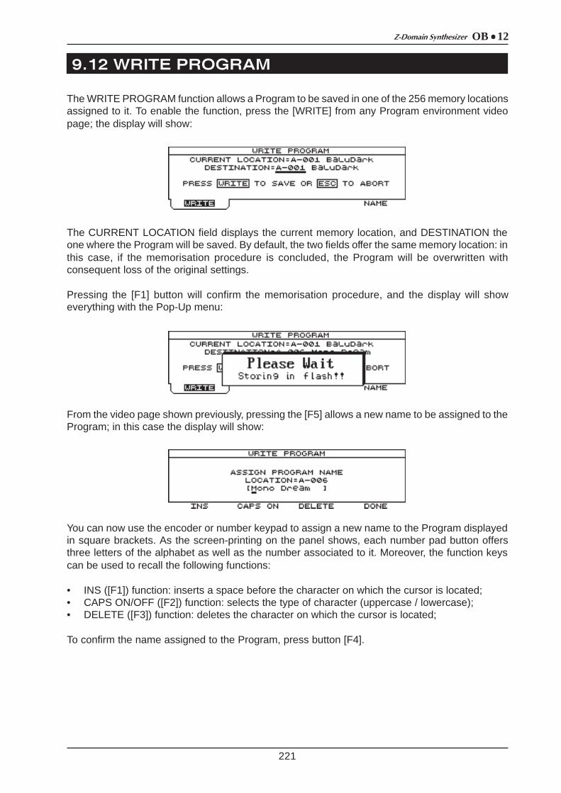
OB 12Z-Domain Synthesizer
9. 12 WRITE PROGRAM
221
The WRITE PROGRAM function allows a Program to be saved in one of the 256 memory locationsassigned to it. To enable the function, press the [WRITE] from any Program environment videopage; the display will show:
The CURRENT LOCATION field displays the current memory location, and DESTINATION theone where the Program will be saved. By default, the two fields offer the same memory location: inthis case, if the memorisation procedure is concluded, the Program will be overwritten withconsequent loss of the original settings.
Pressing the [F1] button will confirm the memorisation procedure, and the display will showeverything with the Pop-Up menu:
From the video page shown previously, pressing the [F5] allows a new name to be assigned to theProgram; in this case the display will show:
You can now use the encoder or number keypad to assign a new name to the Program displayedin square brackets. As the screen-printing on the panel shows, each number pad button offersthree letters of the alphabet as well as the number associated to it. Moreover, the function keyscan be used to recall the following functions:
• INS ([F1]) function: inserts a space before the character on which the cursor is located;• CAPS ON/OFF ([F2]) function: selects the type of character (uppercase / lowercase);• DELETE ([F3]) function: deletes the character on which the cursor is located;
To confirm the name assigned to the Program, press button [F4].
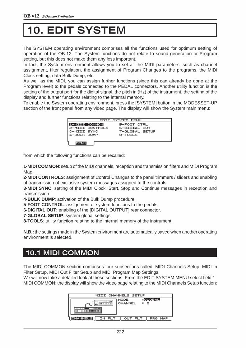
OB 12 Z-Domain Synthesizer
10. EDIT SYSTEM
10.1 MIDI COMMON
222
The SYSTEM operating environment comprises all the functions used for optimum setting ofoperation of the OB-12. The System functions do not relate to sound generation or Programsetting, but this does not make them any less important.In fact, the System environment allows you to set all the MIDI parameters, such as channelassignment, filter regulation, the assignment of Program Changes to the programs, the MIDIClock setting, data Bulk Dump, etc.As well as the MIDI, you can assign further functions (since this can already be done at theProgram level) to the pedals connected to the PEDAL connectors. Another utility function is thesetting of the output port for the digital signal, the pitch in (Hz) of the instrument, the setting of thedisplay and further functions relating to the internal memory.To enable the System operating environment, press the [SYSTEM] button in the MODE&SET-UPsection of the front panel from any video page. The display will show the System main menu:
from which the following functions can be recalled:
1-MIDI COMMON: setup of the MIDI channels, reception and transmission filters and MIDI ProgramMap.2-MIDI CONTROLS: assignment of Control Changes to the panel trimmers / sliders and enablingof transmission of exclusive system messages assigned to the controls.3-MIDI SYNC: setting of the MIDI Clock, Start, Stop and Continue messages in reception andtransmission.4-BULK DUMP : activation of the Bulk Dump procedure.5-FOOT CONTROL: assignment of system functions to the pedals.6-DIGITAL OUT : enabling of the [DIGITAL OUTPUT] rear connector.7-GLOBAL SETUP : system global settings.8-TOOLS : utility function relating to the internal memory of the instrument.
N.B.: the settings made in the System environment are automatically saved when another operatingenvironment is selected.
The MIDI COMMON section comprises four subsections called: MIDI Channels Setup, MIDI InFilter Setup, MIDI Out Filter Setup and MIDI Program Map Settings.We will now take a detailed look at these sections. From the EDIT SYSTEM MENU select field 1-MIDI COMMON; the display will show the video page relating to the MIDI Channels Setup function:
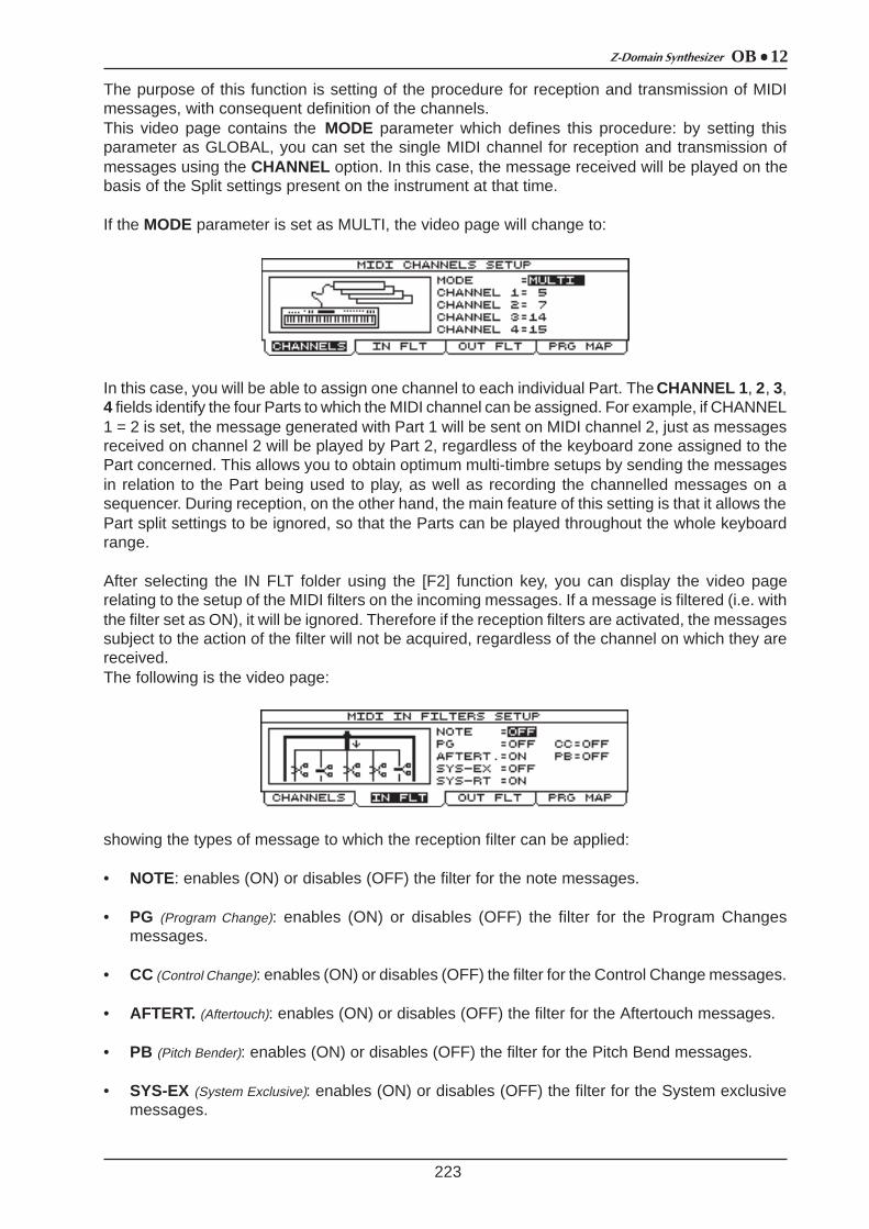
OB 12Z-Domain Synthesizer
223
The purpose of this function is setting of the procedure for reception and transmission of MIDImessages, with consequent definition of the channels.This video page contains the MODE parameter which defines this procedure: by setting thisparameter as GLOBAL, you can set the single MIDI channel for reception and transmission ofmessages using the CHANNEL option. In this case, the message received will be played on thebasis of the Split settings present on the instrument at that time.
If the MODE parameter is set as MULTI, the video page will change to:
In this case, you will be able to assign one channel to each individual Part. The CHANNEL 1 , 2, 3,4 fields identify the four Parts to which the MIDI channel can be assigned. For example, if CHANNEL1 = 2 is set, the message generated with Part 1 will be sent on MIDI channel 2, just as messagesreceived on channel 2 will be played by Part 2, regardless of the keyboard zone assigned to thePart concerned. This allows you to obtain optimum multi-timbre setups by sending the messagesin relation to the Part being used to play, as well as recording the channelled messages on asequencer. During reception, on the other hand, the main feature of this setting is that it allows thePart split settings to be ignored, so that the Parts can be played throughout the whole keyboardrange.
After selecting the IN FLT folder using the [F2] function key, you can display the video pagerelating to the setup of the MIDI filters on the incoming messages. If a message is filtered (i.e. withthe filter set as ON), it will be ignored. Therefore if the reception filters are activated, the messagessubject to the action of the filter will not be acquired, regardless of the channel on which they arereceived.The following is the video page:
showing the types of message to which the reception filter can be applied:
• NOTE: enables (ON) or disables (OFF) the filter for the note messages.
• PG (Program Change): enables (ON) or disables (OFF) the filter for the Program Changesmessages.
• CC (Control Change): enables (ON) or disables (OFF) the filter for the Control Change messages.
• AFTERT. (Aftertouch): enables (ON) or disables (OFF) the filter for the Aftertouch messages.
• PB (Pitch Bender): enables (ON) or disables (OFF) the filter for the Pitch Bend messages.
• SYS-EX (System Exclusive): enables (ON) or disables (OFF) the filter for the System exclusivemessages.

OB 12 Z-Domain Synthesizer
224
• SYS-RT (System Realtime): enables (ON) or disables (OFF) the filter for the System Real Timemessages.
You can now select the OUT FLT folder with function key [F2] to display the video page relating tosetting of the MIDI filters on outgoing messages. Filtering a message (by setting the filter as ON)means not transmitting it. These filters are also independent of the channel setting. Therefore, amessage for transmission will be affected by the action of the filter regardless of the channel onwhich it is transmitted. Please refer to the IN FLT video page concerning the displayd MIDI messagestypes.The display will show the following video page:
You can how use function key [F4] to display the MIDI PROGRAM MAP video page, allowing youto assign the incoming Program Changes freely to the individual Programs or Timbres. With thefunction disabled, Program Change 1 will recall Program or Timbre A-001 (depending on the BankSelect messages). Thanks to the MIDI Program Map you can assign Program A-023 to ProgramChange 1, for example: if this is done, when the instrument receives this PG it will activate ProgramA-023 and not A-001. You can also assign another PG to a Timbre, so when this PG is receivedthe Timbre associated to it will be activated.
As we have described, when the MIDI Program Map is disabled, the instrument’s ProgramChangeðmemory location associations are standard. You can use the BANK SELECT MSB andBANK SELECT LSB to select whether to recall Program or Timbre memory locations.The BANK SELECTS are used as follows:
The video page relating to the MIDI Program Map comprises:
containing the following programming parameters:
• STATUS: enables (ON) or disables (OFF) the MIDI Program Map.
• PRG RECEIVED (Program Change Received): selects the Program Change which recalls thememory location set using the LOCATION TYPE and BANK NUMBER parameters.
BANK SELECT MSB BANK SELECT LSBRECALLED MEMORY
SECTION
0÷63 0÷63 bank A of TIMBRE section
0÷63 64÷127 bank B of TIMBRE section
64÷127 0÷63bank A of PROGRAM
section
64÷127 64 ÷127bank B of PROGRAM
section
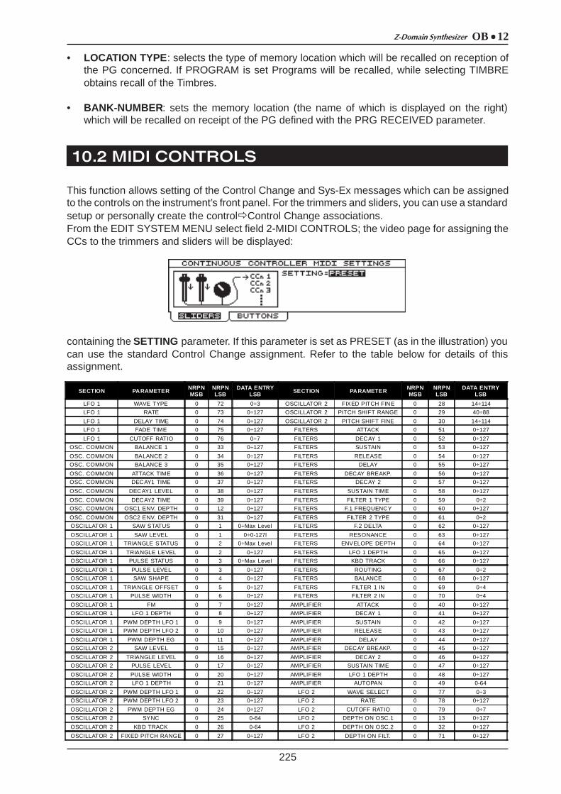
OB 12Z-Domain Synthesizer
10.2 MIDI CONTROLS
225
• LOCATION TYPE : selects the type of memory location which will be recalled on reception ofthe PG concerned. If PROGRAM is set Programs will be recalled, while selecting TIMBREobtains recall of the Timbres.
• BANK-NUMBER : sets the memory location (the name of which is displayed on the right)which will be recalled on receipt of the PG defined with the PRG RECEIVED parameter.
This function allows setting of the Control Change and Sys-Ex messages which can be assignedto the controls on the instrument’s front panel. For the trimmers and sliders, you can use a standardsetup or personally create the controlðControl Change associations.From the EDIT SYSTEM MENU select field 2-MIDI CONTROLS; the video page for assigning theCCs to the trimmers and sliders will be displayed:
containing the SETTING parameter. If this parameter is set as PRESET (as in the illustration) youcan use the standard Control Change assignment. Refer to the table below for details of thisassignment.
SECTION PARAMETER NRPNMSB
NRPNLSB
DATA ENTRYLSB SECTION PARAMETER NRPN
MSBNRPNLSB
DATA ENTRYLSB
LFO 1 WAVE TYPE 0 72 0÷3 OSCILLATOR 2 FIXED PITCH FINE 0 28 14÷114
LFO 1 RATE 0 73 0÷127 OSCILLATOR 2 PITCH SHIFT RANGE 0 29 40÷88
LFO 1 DELAY TIME 0 74 0÷127 OSCILLATOR 2 PITCH SHIFT FINE 0 30 14÷114
LFO 1 FADE TIME 0 75 0÷127 FILTERS ATTACK 0 51 0÷127
LFO 1 CUTOFF RATIO 0 76 0÷7 FILTERS DECAY 1 0 52 0÷127
OSC. COMMON BALANCE 1 0 33 0÷127 FILTERS SUSTAIN 0 53 0÷127
OSC. COMMON BALANCE 2 0 34 0÷127 FILTERS RELEASE 0 54 0÷127
OSC. COMMON BALANCE 3 0 35 0÷127 FILTERS DELAY 0 55 0÷127
OSC. COMMON ATTACK TIME 0 36 0÷127 FILTERS DECAY BREAKP. 0 56 0÷127
OSC. COMMON DECAY1 TIME 0 37 0÷127 FILTERS DECAY 2 0 57 0÷127
OSC. COMMON DECAY1 LEVEL 0 38 0÷127 FILTERS SUSTAIN TIME 0 58 0÷127
OSC. COMMON DECAY2 TIME 0 39 0÷127 FILTERS FILTER 1 TYPE 0 59 0÷2
OSC. COMMON OSC1 ENV. DEPTH 0 12 0÷127 FILTERS F.1 FREQUENCY 0 60 0÷127
OSC. COMMON OSC2 ENV. DEPTH 0 31 0÷127 FILTERS FILTER 2 TYPE 0 61 0÷2
OSCILLATOR 1 SAW STATUS 0 1 0÷Max Level FILTERS F.2 DELTA 0 62 0÷127
OSCILLATOR 1 SAW LEVEL 0 1 0÷0-127l FILTERS RESONANCE 0 63 0÷127
OSCILLATOR 1 TRIANGLE STATUS 0 2 0÷Max Level FILTERS ENVELOPE DEPTH 0 64 0÷127
OSCILLATOR 1 TRIANGLE LEVEL 0 2 0÷127 FILTERS LFO 1 DEPTH 0 65 0÷127
OSCILLATOR 1 PULSE STATUS 0 3 0÷Max Level FILTERS KBD TRACK 0 66 0÷127
OSCILLATOR 1 PULSE LEVEL 0 3 0÷127 FILTERS ROUTING 0 67 0÷2
OSCILLATOR 1 SAW SHAPE 0 4 0÷127 FILTERS BALANCE 0 68 0÷127
OSCILLATOR 1 TRIANGLE OFFSET 0 5 0÷127 FILTERS FILTER 1 IN 0 69 0÷4
OSCILLATOR 1 PULSE WIDTH 0 6 0÷127 FILTERS FILTER 2 IN 0 70 0÷4
OSCILLATOR 1 FM 0 7 0÷127 AMPLIFIER ATTACK 0 40 0÷127
OSCILLATOR 1 LFO 1 DEPTH 0 8 0÷127 AMPLIFIER DECAY 1 0 41 0÷127
OSCILLATOR 1 PWM DEPTH LFO 1 0 9 0÷127 AMPLIFIER SUSTAIN 0 42 0÷127
OSCILLATOR 1 PWM DEPTH LFO 2 0 10 0÷127 AMPLIFIER RELEASE 0 43 0÷127
OSCILLATOR 1 PWM DEPTH EG 0 11 0÷127 AMPLIFIER DELAY 0 44 0÷127
OSCILLATOR 2 SAW LEVEL 0 15 0÷127 AMPLIFIER DECAY BREAKP. 0 45 0÷127
OSCILLATOR 2 TRIANGLE LEVEL 0 16 0÷127 AMPLIFIER DECAY 2 0 46 0÷127
OSCILLATOR 2 PULSE LEVEL 0 17 0÷127 AMPLIFIER SUSTAIN TIME 0 47 0÷127
OSCILLATOR 2 PULSE WIDTH 0 20 0÷127 AMPLIFIER LFO 1 DEPTH 0 48 0÷127
OSCILLATOR 2 LFO 1 DEPTH 0 21 0÷127 AMPLIFIER AUTOPAN 0 49 0-64
OSCILLATOR 2 PWM DEPTH LFO 1 0 22 0÷127 LFO 2 WAVE SELECT 0 77 0÷3
OSCILLATOR 2 PWM DEPTH LFO 2 0 23 0÷127 LFO 2 RATE 0 78 0÷127
OSCILLATOR 2 PWM DEPTH EG 0 24 0÷127 LFO 2 CUTOFF RATIO 0 79 0÷7
OSCILLATOR 2 SYNC 0 25 0-64 LFO 2 DEPTH ON OSC.1 0 13 0÷127
OSCILLATOR 2 KBD TRACK 0 26 0-64 LFO 2 DEPTH ON OSC.2 0 32 0÷127
OSCILLATOR 2 FIXED PITCH RANGE 0 27 0÷127 LFO 2 DEPTH ON FILT. 0 71 0÷127
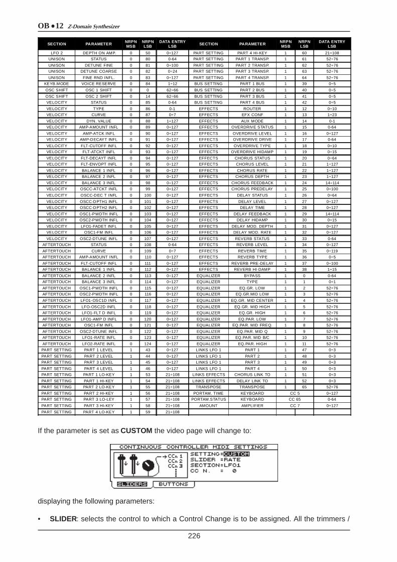
OB 12 Z-Domain Synthesizer
226
SECTION PARAMETER NRPNMSB
NRPNLSB
DATA ENTRYLSB SECTION PARAMETER NRPN
MSBNRPNLSB
DATA ENTRYLSB
LFO 2 DEPTH ON AMP. 0 50 0÷127 PART SETTING PART 4 HI-KEY 1 60 21÷108
UNISON STATUS 0 80 0-64 PART SETTING PART 1 TRANSP. 1 61 52÷76
UNISON DETUNE FINE 0 81 0÷100 PART SETTING PART 2 TRANSP. 1 62 52÷76
UNISON DETUNE COARSE 0 82 0÷24 PART SETTING PART 3 TRANSP. 1 63 52÷76
UNISON FINE RND INFL. 0 83 0÷127 PART SETTING PART 4 TRANSP. 1 64 52÷76
KEYB.MODE VOICE RESERVE 0 84 1÷12 BUS SETTING PART 1 BUS 1 39 0÷5
OSC SHIFT OSC 1 SHIFT 0 0 62÷66 BUS SETTING PART 2 BUS 1 40 0÷5
OSC SHIFT OSC 2 SHIFT 0 14 62÷66 BUS SETTING PART 3 BUS 1 41 0÷5
VELOCITY STATUS 0 85 0-64 BUS SETTING PART 4 BUS 1 42 0÷5
VELOCITY TYPE 0 86 0-1 EFFECTS ROUTER 1 12 0÷10
VELOCITY CURVE 0 87 0÷7 EFFECTS EFX CONF 1 13 1÷23
VELOCITY DYN. VALUE 0 88 1÷127 EFFECTS AUX MODE 1 14 0-1
VELOCITY AMP-AMOUNT INFL 0 89 0÷127 EFFECTS OVERDRIVE STATUS 1 15 0-64
VELOCITY AMP-ATCK INFL 0 90 0÷127 EFFECTS OVERDRIVE LEVEL 1 16 0÷127
VELOCITY AMP-DECAYT INFL 0 91 0÷127 EFFECTS OVERDRIVE DRIVE 1 17 0-64
VELOCITY FLT-CUTOFF INFL 0 92 0÷127 EFFECTS OVERDRIVE TYPE 1 18 0÷10
VELOCITY FLT-ATCKT INFL 0 93 0÷127 EFFECTS OVERDRIVE HIDAMP 1 19 0÷15
VELOCITY FLT-DECAYT INFL 0 94 0÷127 EFFECTS CHORUS STATUS 1 20 0÷64
VELOCITY FLT-ENVDPT INFL 0 95 0÷127 EFFECTS CHORUS LEVEL 1 21 1÷127
VELOCITY BALANCE 1 INFL 0 96 0÷127 EFFECTS CHORUS RATE 1 22 1÷127
VELOCITY BALANCE 2 INFL 0 97 0÷127 EFFECTS CHORUS DEPTH 1 23 1÷127
VELOCITY BALANCE 3 INFL 0 98 0÷127 EFFECTS CHORUS FEEDBACK 1 24 14÷114
VELOCITY OSCC-ATCKT INFL 0 99 0÷127 EFFECTS CHORUS PREDELAY 1 25 0÷100
VELOCITY OSCC-DEC T INFL 0 100 0÷127 EFFECTS DELAY STATUS 1 26 0÷64
VELOCITY OSCC-DPTH1 INFL 0 101 0÷127 EFFECTS DELAY LEVEL 1 27 0÷127
VELOCITY OSCC-DPTH2 INFL 0 102 0÷127 EFFECTS DELAY TIME 1 28 0÷127
VELOCITY OSC1-PWDTH INFL 0 103 0÷127 EFFECTS DELAY FEEDBACK 1 29 14÷114
VELOCITY OSC2-PWDTH INFL 0 104 0÷127 EFFECTS DELAY HIDAMP 1 30 0÷15
VELOCITY LFO1-FADET INFL 0 105 0÷127 EFFECTS DELAY MOD. DEPTH 1 31 0÷127
VELOCITY OSC1-FM INFL 0 106 0÷127 EFFECTS DELAY MOD. RATE 1 32 0÷127
VELOCITY OSC2-DTUNE INFL 0 107 0÷127 EFFECTS REVERB STATUS 1 33 0-64
AFTERTOUCH STATUS 0 108 0-64 EFFECTS REVERB LEVEL 1 34 0÷127
AFTERTOUCH CURVE 0 109 0÷7 EFFECTS REVERB TIME 1 35 0÷119
AFTERTOUCH AMP-AMOUNT INFL 0 110 0÷127 EFFECTS REVERB TYPE 1 36 0÷5
AFTERTOUCH FLT-CUTOFF INFL 0 111 0÷127 EFFECTS REVERB PRE-DELAY 1 37 0÷100
AFTERTOUCH BALANCE 1 INFL 0 112 0÷127 EFFECTS REVERB HI-DAMP 1 38 1÷15
AFTERTOUCH BALANCE 2 INFL 0 113 0÷127 EQUALIZER BYPASS 1 0 0-64
AFTERTOUCH BALANCE 3 INFL 0 114 0÷127 EQUALIZER TYPE 1 1 0÷1
AFTERTOUCH OSC1-PWDTH INFL 0 115 0÷127 EQUALIZER EQ.GR. LOW 1 2 52÷76
AFTERTOUCH OSC2-PWDTH INFL 0 116 0÷127 EQUALIZER EQ.GR.MID LOW 1 3 52÷76
AFTERTOUCH LFO1-OSC1D INFL 0 117 0÷127 EQUALIZER EQ.GR. MID CENTER 1 4 52÷76
AFTERTOUCH LFO-OSC2D INFL 0 118 0÷127 EQUALIZER EQ.GR. MID HIGH 1 5 52÷76
AFTERTOUCH LFO1-FLT D INFL 0 119 0÷127 EQUALIZER EQ.GR. HIGH 1 6 52÷76
AFTERTOUCH LFO1-AMP D INFL 0 120 0÷127 EQUALIZER EQ.PAR. LOW 1 7 52÷76
AFTERTOUCH OSC1-FM INFL 0 121 0÷127 EQUALIZER EQ.PAR. MID FREQ. 1 8 52÷76
AFTERTOUCH OSC2-DTUNE INFL 0 122 0÷127 EQUALIZER EQ.PAR. MID Q 1 9 52÷76
AFTERTOUCH LFO1-RATE INFL 0 123 0÷127 EQUALIZER EQ.PAR. MID B/C 1 10 52÷76
AFTERTOUCH LFO2-RATE INFL 0 124 0÷127 EQUALIZER EQ.PAR. HIGH 1 11 52÷76
PART SETTING PART 1 LEVEL 1 43 0÷127 LINKS LFO 1 PART 1 1 47 0÷3
PART SETTING PART 2 LEVEL 1 44 0÷127 LINKS LFO 1 PART 2 1 48 0÷3
PART SETTING PART 3 LEVEL 1 45 0÷127 LINKS LFO 1 PART 3 1 49 0÷3
PART SETTING PART 4 LEVEL 1 46 0÷127 LINKS LFO 1 PART 4 1 50 0÷3
PART SETTING PART 1 LO-KEY 1 53 21÷108 LINKS EFFECTS CHORUS LINK TO 1 51 0÷3
PART SETTING PART 1 HI-KEY 1 54 21÷108 LINKS EFFECTS DELAY LINK TO 1 52 0÷3
PART SETTING PART 2 LO-KEY 1 55 21÷108 TRANSPOSE TRANSPOSE 1 65 52÷76
PART SETTING PART 2 HI-KEY 1 56 21÷108 PORTAM. TIME KEYBOARD CC 5 0÷127
PART SETTING PART 3 LO-LEY 1 57 21÷108 PORTAM.STATUS KEYBOARD CC 65 0-64
PART SETTING PART 3 HI-KEY 1 58 21÷108 AMOUNT AMPLIFIER CC 7 0÷127
PART SETTING PART 4 LO-KEY 1 59 21÷108
If the parameter is set as CUSTOM the video page will change to:
displaying the following parameters:
• SLIDER: selects the control to which a Control Change is to be assigned. All the trimmers /

OB 12Z-Domain Synthesizer
227
sliders on the front panel can be selected.
• SECTION (not selectable): displays the section containing the control specified with the SLIDERparameter.
• CC N. (Control Change Number): assigns the Control Change to the control specified with theSLIDER parameter.
Using function key [F2] to select the BUTTONS folder allows you to display the video page relatingto the exclusive system messages:
You can use the SEND SYS-EX parameter to decide whether to send (ON) or not to send (OFF)the exclusive system strings assigned to the panel controls.
SWITCH SECTION SYSTEM EXCLUSIVE SWITCH SECTION SYSTEM EXCLUSIVE[F1] DISPLAY F0 31 30 00 04 00 39 01 60 F7 [MODE] ARPEGGIO F0 31 30 00 04 00 67 01 32 F7
[F2] DISPLAY F0 31 30 00 04 00 3A 01 5F F7 [RANGE] ARPEGGIO F0 31 30 00 04 00 68 01 31 F7
[F3] DISPLAY F0 31 30 00 04 00 3B 01 5F F7 [ON/OFF] PHRASE F0 31 30 00 04 00 69 01 30 F7
[F4] DISPLAY F0 31 30 00 04 00 3C 01 5D F7 [REC] PHRASE F0 31 30 00 04 00 6A 01 2F F7
[LEFT] CURSOR F0 31 30 00 04 00 3D 01 5C F7 [TAP TEMPO] PHRASE F0 31 30 00 04 00 6B 01 2E F7
[UP] CURSOR F0 31 30 00 04 00 3E 01 5B F7 [MODE] EQUALIZER F0 31 30 00 04 00 6C 01 2D F7
[RIGHT] CURSOR F0 31 30 00 04 00 3F 01 5A F7 [BYPASS] EQUALIZER F0 31 30 00 04 00 6D 01 2C F7
[DOW N] CURSOR F0 31 30 00 04 00 40 01 59 F7 [HOLD] RIBBON CONTROLLER F0 31 30 00 04 00 6E 01 2B F7
[ENCODER UP] CURSOR F0 31 30 00 04 00 41 01 58 F7 [RELATIVE] RIBBON CONTROLLER F0 31 30 00 04 00 6F 01 2A F7
[ENCODER DOW N] CURSOR F0 31 30 00 04 00 42 01 57 F7 [VELOCITY] KEYBOARD SENSE F0 31 30 00 04 00 70 01 29 F7
[ESC] DISPLAY F0 31 30 00 04 00 43 01 56 F7 [STND-M.MORPH] WHELL MODE F0 31 30 00 04 00 71 01 28 F7
[ENTER] NUMERIC PAD F0 31 30 00 04 00 44 01 55 F7 [AFTERTOUCH] KEYBOARD SENSE F0 31 30 00 04 00 72 01 27 F7
[W AVE] LFO 1 F0 31 30 00 04 00 45 01 54 F7 [AFTER. EXCHANGE] WHELL MODE F0 31 30 00 04 00 73 01 26 F7
[W AVE] LFO 2 F0 31 30 00 04 00 46 01 53 F7 [DISP HOLD] DISPLAY F0 31 30 00 04 00 74 01 25 F7
[DEPTH] LFO 2 F0 31 30 00 04 00 47 01 52 F7 [PART 1] KEYBOARD MODE AND… F0 31 30 00 04 00 75 01 24 F7
[OSC 1 OSC 2] OSCILLATOR COMMON F0 31 30 00 04 00 48 01 51 F7 [PART 2] KEYBOARD MODE AND… F0 31 30 00 04 00 76 01 23 F7
[SAW ON/OFF] OSCILLATOR 1 F0 31 30 00 04 00 49 01 50 F7 [PART 3] KEYBOARD MODE AND… F0 31 30 00 04 00 77 01 22 F7
[TRIANGLE ON/OFF] OSCILLATOR 1 F0 31 30 00 04 00 4A 01 4F F7 [PART 4] KEYBOARD MODE AND… F0 31 30 00 04 00 78 01 21 F7
[PULSE ON/OFF] OSCILLATOR 1 F0 31 30 00 04 00 4F 01 4A F7 [SPLIT] KEYBOARD MODE AND… F0 31 30 00 04 00 79 01 20 F7
[PWM LFO1-LFO2-EG] OSCILLATOR 1 F0 31 30 00 04 00 4C 01 4D F7 [LAYER] KEYBOARD MODE AND… F0 31 30 00 04 00 7A 01 1F F7
[SAW ON/OFF] OSCILLATOR 2 F0 31 30 00 04 00 4D 01 4C F7 [SINGLE] KEYBOARD MODE AND… F0 31 30 00 04 00 7B 01 1E F7
[TRIANGLE ON/OFF] OSCILLATOR 2 F0 31 30 00 04 00 4E 01 4B F7 [PROGRAM] MODE & SET-UP F0 31 30 00 04 00 7C 01 1D F7
[PWM LFO1-LFO2-EG] OSCILLATOR 2 F0 31 30 00 04 00 50 01 49 F7 [TIMBRE] MODE & SET-UP F0 31 30 00 04 00 7D 01 1C F7
[SYNC] OSCILLATOR 2 F0 31 30 00 04 00 51 01 48 F7 [PANEL SCAN] MODE & SET-UP F0 31 30 00 04 00 7E 01 1B F7
[KBD TRACK] OSCILLATOR 2 F0 31 30 00 04 00 52 01 47 F7 [SYSTEM] MODE & SET-UP F0 31 30 00 04 00 7F 01 1A F7
[FILTER 1] FILTERS F0 31 30 00 04 00 53 01 46 F7 [EFFECTS] MODE & SET-UP F0 31 30 00 04 01 00 01 18 F7
[FILTER 2] FILTERS F0 31 30 00 04 00 54 01 45 F7 [W RITE] MODE & SET-UP F0 31 30 00 04 01 01 01 17 F7
[ROUTING] FILTERS F0 31 30 00 04 00 55 01 44 F7 [AUTOMORPH] MODE & SET-UP F0 31 30 00 04 01 02 01 16 F7
[AUTOPAN] AMPLIFIER F0 31 30 00 04 00 57 01 42 F7 [MANMORPH] MODE & SET-UP F0 31 30 00 04 01 03 01 15 F7
[MONO] KEYBOARD F0 31 30 00 04 00 58 01 41 F7 [MOTION 1] AUTOMATION F0 31 30 00 04 01 05 01 13 F7
[PORTAMENTO] KEYBOARD F0 31 30 00 04 00 59 01 40 F7 [MOTION 2] AUTOMATION F0 31 30 00 04 01 06 01 12 F7
[UNISON] KEYBOARD F0 31 30 00 04 00 5A 01 3F F7 [MOTION REC] AUTOMATION F0 31 30 00 04 01 07 01 11 F7
[LEGATO] KEYBOARD F0 31 30 00 04 00 5B 01 3E F7 [BANK] NUMERIC PAD F0 31 30 00 04 01 08 01 10 F7
[OCT-] KEYBOARD F0 31 30 00 04 00 5C 01 3D F7 [0 SPACE] NUMERIC PAD F0 31 30 00 04 01 09 01 0F F7
[OCT+] KEYBOARD F0 31 30 00 04 00 5D 01 3C F7 [1 ABC] NUMERIC PAD F0 31 30 00 04 01 0A 01 0E F7
[OSC SHIFT] KEYBOARD F0 31 30 00 04 00 5E 01 3B F7 [2 DEF] NUMERIC PAD F0 31 30 00 04 01 0B 01 0D F7
[LEVEL/PARAMETER] EFFECTS F0 31 30 00 04 00 5F 01 3A F7 [3 GHI] NUMERIC PAD F0 31 30 00 04 01 0C 01 0C F7
[OVERDRIVE] EFFECTS F0 31 30 00 04 00 60 01 39 F7 [4 JKL] NUMERIC PAD F0 31 30 00 04 01 0D 01 0B F7
[CHORUS] EFFECTS F0 31 30 00 04 00 61 01 38 F7 [5 MNO] NUMERIC PAD F0 31 30 00 04 01 0E 01 0A F7
[DELAY] EFFECTS F0 31 30 00 04 00 62 01 37 F7 [6 PQR] NUMERIC PAD F0 31 30 00 04 01 0F 01 09 F7
[REVERB] EFFECTS F0 31 30 00 04 00 63 01 36 F7 [7 STU] NUMERIC PAD F0 31 30 00 04 01 10 01 08 F7
[TAP TEMPO] ARPEGGIO F0 31 30 00 04 00 65 01 34 F7 [8 VW X] NUMERIC PAD F0 30 31 00 04 01 11 01 07 F7
[ON/OFF] ARPEGGIO F0 31 30 00 04 00 66 01 33 F7 [9 YZ!] NUMERIC PAD F0 31 30 00 04 01 12 01 96 F7

OB 12 Z-Domain Synthesizer
10.3 MIDI SYNC
228
This section of the SYSTEM menu allows you to set the parameters relating to the MIDI Clock forsynchronisation of the Phrase Recorder, the Arpeggio, LFO1 and LFO2 with remote MIDI units.If, for example, you are using a remote sequencer to control the OB-12 sound generation sectionand you are also playing on the instrument’s keyboard, by synchronising the Arpeggio or LFO1 orLFO2 with the sequencer performance time (identified by the MIDI Clock transmitted by thesequencer itself), you can use an arpeggio tempo and/or LFO1/2 modulation frequency identicalto the sequencer performance tempo.You can also synchronise the OB-12 Phrase Recorder recording time with the performance timeof a remote sequencer, to ensure perfect recording of the data contained in the sequencer.
N.B.: Some MIDI instruments only transmit MIDI Clock messages during recording and/or playback.Consult the user manuals of these units to check the exact MIDI Clock transmission mode. Moreover,if the remote MIDI instrument connected to the OB-12 transmits MIDI Real Time STOP messagesat the end of the playback the synchronisation might not take place correctly.
Other settings in this function concern the MIDI Real Time START, STOP and CONTINUE messagestransmitted and received. The OB-12 is able to transmit these MIDI messages on the basis of thecommands used on the Arpeggio, the Phrase Recorder, the Motion Recorder and the Auto Morph.This means that you can send these MIDI messages (to start and stop a MIDI sequence recordedin a sequencer, for example) by activating and deactivating the functions referred to above (bypressing and releasing a keyboard key for the Arpeggio and Phrase Recorder, and using the[LOC1] / [LOC2] buttons for the Motion Record and the [AUTO] button for the Auto Morph). Youcan also set the section (Motion 1, Motion 2 and Auto Morph) to which incoming MIDI Real Timemessages will be sent.
But we will now see how to set the parameters associated to the MIDI Clock.From the SYSTEM menu, select option 3-MIDI SYNC; the display will show the following videopage:
containing the following parameters:
• STATUS: activates (ON) and/or deactivates (OFF) transmission of the MIDI Clock.
• SOURCE: sets the section from which the MIDI Clock is to be generated. This MIDI messagecan be linked to the following sections:
- LFO1: the MIDI Clock transmitted will be synchronised to the LFO1 RATE parameter.- LFO2: the MIDI Clock transmitted will be synchronised to the LFO2 RATE parameter.- ARPEGGIO: the MIDI Clock transmitted will be synchronised with the Arpeggio TEMPO
parameter.- PHRASE RECORDER: the MIDI Clock transmitted will be synchronised with the Phrase
Recorder TEMPO parameter.
• MULTIPLIER : sets the multiplication factor of the MIDI Clock in relation to the parameter towhich it is linked. For example, if this parameter is set at 2.0X, the message will be transmitted

OB 12Z-Domain Synthesizer
229
at twice the speed of the signal (for example, the arpeggio tempo or the LFO Rate) with whichit is synchronised. The values available range from 0.1X to 10X.
Pressing the [F2] function key displays the video page relating to the MIDI Real Time messagestransmitted:
These are the parameters which can be adjusted:
• STATUS: enables (ON) and/or disables (OFF) transmission of the MIDI Real Time messages.
• SOURCE: specifies the system from which the Start, Stop and Continue instructions are to betaken. The possible choices are:
- ARPEGGIO: when the Arpeggio is activated by pressing a keyboard key, the MIDI STARTmessage will be sent. When the key is released (interrupting the Arpeggio), the STOPmessage will be sent.Depending on the setting of the STOP AS parameter, pressing a key again will send theSTART/STOP or CONTINUE messages.
- PHRASE REC: when a Phrase is recalled by pressing a keyboard key, the MIDI STARTmessage will be sent. When the key is released (interrupting the playing of the phrase), theSTOP message will be sent.Depending on the setting of the STOP AS parameter, pressing a key again will send theSTART/STOP or CONTINUE messages.
- MOTION REC1: when Motion 1 is activated, the START message will be sent. When it isinterrupted, the STOP message will be sent.Depending on the setting of the STOP AS parameter, reactivating the Motion will send theSTART/STOP or CONTINUE messages.
- MOTION REC2: when Motion 2 is activated, the START message will be sent. When it isinterrupted, the STOP message will be sent.Depending on the setting of the STOP AS parameter, reactivating the Motion will send theSTART/STOP or CONTINUE messages.
- AUTO MORPH: when the automatic Morphing is activated, the START message will besent. When performance of the Morphing is interrupted, the STOP message will be sent.Depending on the setting of the STOP AS parameter, reactivating the function concernedwill send the START/STOP or CONTINUE messages.
• STOP AS : defines which MIDI Real Time messages will be transmitted when the section withwhich they are associated is activated and/or disabled. The table below indicates the messages sent depending on the setting of the parameter.
The next video page, displayed by pressing the [F3] function key, allows you to set the parametersrelating to the MIDI Real Time messages received.
STOP AS: STOP STOP AS: CONTINUE
Function start START START
Function stop STOP PAUSE
Next function start START CONTINUE
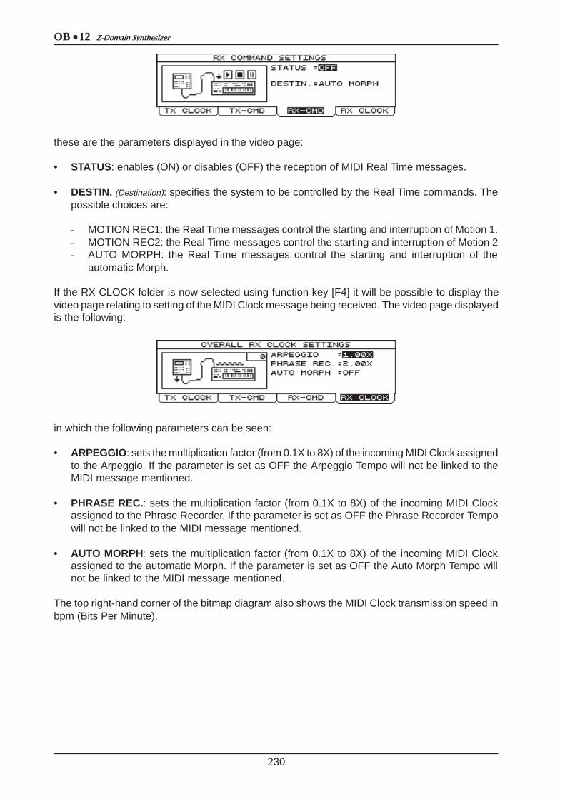
OB 12 Z-Domain Synthesizer
230
these are the parameters displayed in the video page:
• STATUS: enables (ON) or disables (OFF) the reception of MIDI Real Time messages.
• DESTIN. (Destination): specifies the system to be controlled by the Real Time commands. Thepossible choices are:
- MOTION REC1: the Real Time messages control the starting and interruption of Motion 1.- MOTION REC2: the Real Time messages control the starting and interruption of Motion 2- AUTO MORPH: the Real Time messages control the starting and interruption of the
automatic Morph.
If the RX CLOCK folder is now selected using function key [F4] it will be possible to display thevideo page relating to setting of the MIDI Clock message being received. The video page displayedis the following:
in which the following parameters can be seen:
• ARPEGGIO: sets the multiplication factor (from 0.1X to 8X) of the incoming MIDI Clock assignedto the Arpeggio. If the parameter is set as OFF the Arpeggio Tempo will not be linked to theMIDI message mentioned.
• PHRASE REC.: sets the multiplication factor (from 0.1X to 8X) of the incoming MIDI Clockassigned to the Phrase Recorder. If the parameter is set as OFF the Phrase Recorder Tempowill not be linked to the MIDI message mentioned.
• AUTO MORPH: sets the multiplication factor (from 0.1X to 8X) of the incoming MIDI Clockassigned to the automatic Morph. If the parameter is set as OFF the Auto Morph Tempo willnot be linked to the MIDI message mentioned.
The top right-hand corner of the bitmap diagram also shows the MIDI Clock transmission speed inbpm (Bits Per Minute).
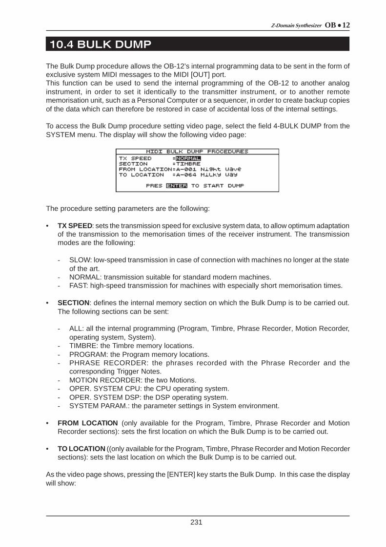
OB 12Z-Domain Synthesizer
10.4 BULK DUMP
231
The Bulk Dump procedure allows the OB-12’s internal programming data to be sent in the form ofexclusive system MIDI messages to the MIDI [OUT] port.This function can be used to send the internal programming of the OB-12 to another analoginstrument, in order to set it identically to the transmitter instrument, or to another remotememorisation unit, such as a Personal Computer or a sequencer, in order to create backup copiesof the data which can therefore be restored in case of accidental loss of the internal settings.
To access the Bulk Dump procedure setting video page, select the field 4-BULK DUMP from theSYSTEM menu. The display will show the following video page:
The procedure setting parameters are the following:
• TX SPEED: sets the transmission speed for exclusive system data, to allow optimum adaptationof the transmission to the memorisation times of the receiver instrument. The transmissionmodes are the following:
- SLOW: low-speed transmission in case of connection with machines no longer at the stateof the art.
- NORMAL: transmission suitable for standard modern machines.- FAST: high-speed transmission for machines with especially short memorisation times.
• SECTION: defines the internal memory section on which the Bulk Dump is to be carried out.The following sections can be sent:
- ALL: all the internal programming (Program, Timbre, Phrase Recorder, Motion Recorder,operating system, System).
- TIMBRE: the Timbre memory locations.- PROGRAM: the Program memory locations.- PHRASE RECORDER: the phrases recorded with the Phrase Recorder and the
corresponding Trigger Notes.- MOTION RECORDER: the two Motions.- OPER. SYSTEM CPU: the CPU operating system.- OPER. SYSTEM DSP: the DSP operating system.- SYSTEM PARAM.: the parameter settings in System environment.
• FROM LOCATION (only available for the Program, Timbre, Phrase Recorder and MotionRecorder sections): sets the first location on which the Bulk Dump is to be carried out.
• TO LOCATION ((only available for the Program, Timbre, Phrase Recorder and Motion Recordersections): sets the last location on which the Bulk Dump is to be carried out.
As the video page shows, pressing the [ENTER] key starts the Bulk Dump. In this case the displaywill show:

OB 12 Z-Domain Synthesizer
10.5 FOOT CONTROL SETUP
232
which displays a progression bar with the relative percentage value of the portion of the datatransmitted.Conversely, the [ESC] key can be pressed to abort the Bulk Dump procedure with consequentconfirmation in the form of the display:
To reload the data in the instrument, connect the transmitter device to the MIDI [IN] port. Onreceipt of the MIDI data, the UPDATING PROCEDURE (see point 11.1) will be displayed, afterwhich the instrument will reset itself to allow the internal circuits to set themselves up with the newsettings.
As we have seen in point 9.6 of this manual, the OB-12 allows specific functions to be assigned tothe pedals which can be connected to the rear sockets. We have already discussed how to assignfunctions to the pedals in the Program environment, with definition of various assignments on thebasis of the Parts which the Program comprises. In this case, the functions assigned to the pedalsdepend on the Program selected.On the other hand, if functions are assigned to the pedals in the System environment, they willremain active regardless of the Program selected. You can therefore use more common functionswith the aid of the assignments in the System environment and use more customised functions,suitable for the selected Program, with assignment of functions in the Program environment.
To access the video pages for assignment of the functions to the pedals, select field 5-FOOTCTRL in the EDIT SYSTEM MENU. The display will show the following video page:
in which the setting parameters of the footswitch pedal connected to the PEDAL [SWITCH1]connector can be modified:
• POLARITY : sets the polarity of the pedal connected. Consult the information provided on thepedal or on its information sheets for details of the exact setup.
• FUNCTION: assigns the function to the footswitch pedal. The functions which can be assignedare the following:

OB 12Z-Domain Synthesizer
233
You can use the [F2] key to select the SWITCH2 folder and display the video page relating tosetting of the second pedal connected to the PEDALS [SWITCH2] connector. Refer to theinformation given for the settings relating to Switch1 for the Switch2 video page.
If you now select the PEDAL1 folder you can display the video page relating to the settings of theexpression pedal connected to the PEDALS [EXP.1] connector.
The parameters which can be modified are the following:
• FUNCTION: assigns the function to the expression pedal.
• MIN and MAX: set the minimum and maximum values of the parameter controlled by thepedal.
The functions which can be assigned to the pedal are described in the table on next page.
SELECTIONS FUNCTIONSCONTROLS ON
PANELSELECTIONS FUNCTIONS
CONTROLS ON PANEL
DISABLED No function applied MOT2 ST/STP Motion Location 1 start/stop[LOC2] of
AUTOMATION
PROGRAM UP single Program forward Encoder AUTO MORPHit cyclically activates and
disactivates the Auto Morph[AUTO] of
AUTOMATION
PROGRAM DOWN
single Program reward EncoderMANUAL MORPH
it cyclically activates and disactivates the Manual Morph
[MANUAL] of AUTOMATION
ARP. ON/OFF Arpeggio on/off[ON/OFF] of ARPEGGIO START MORPH start of selected Morph
[ENABLE] of AUTOMATION
ARP/PHR HLDit cyclically activates and
disactivates the HOLD function of Arpeggio and Phrase Recorder
[HOLD] of ARPEGGIO RIB. CTL HLDit cyclically activates and
disactivates the Hold of the Ribbon Controller
[HOLD] of Ribbon Controller
ARP. MODE-UP
Arpeggio mode change with the sequency
UP>DOWN>UP/DOWN>RANDOM[MODE] of ARPEGGIO RIB. CTL REL
it cyclically activates and disactivates the Relative of the
Ribbon Controller
[RELATIVE] of Ribbon Controller
ARP MODE-DW
Arpeggio mode change with the sequency
RANDOM>UP/DOWM>DOWN>UP[MODE] of ARPEGGIO OVD. BYPASS bypass/activation cyclical of
Overdrive [OVERDRIVE] of
EFFECTS
ARP. OCT-UP single Arpeggio range change with the sequency 0>+1>+2>+3
[RANGE] of ARPEGGIO CHOR. BYPASS bypass/activation cyclical of Chorus [CHORUS] of
EFFECTS
ARP. OCT-DW single Arpeggio range change with the sequency +3>+2>+1>0
[RANGE] of ARPEGGIO DEL. BYPASS bypass/activation cyclical of Delay [DELAY] of EFFECTS
PHR. ON/OFF Phrase Recorder on/off [ON/OFF] of PHRASE REV. BYPASS bypass/activation cyclical of Reverb [REVERB] of
EFFECTS
MOT1 ST/STP Motion Location 1 start/stop[LOC1] of
AUTOMATION EQ. BYPASSbypass/activation cyclical of
Equalizer [BYPASS] of EQUALIZER
SELECTIONSCONTROLLED PARAMETERS
CONTROLS ON PANEL
SELECTIONSCONTROLLED PARAMTERS
CONTROLS ON PANEL
DISABLED none OVD.DRIVE degree of Overdrive
[LEVEL/PARAMETER] of EFFECTS
associated to DRIVE of OVERDRIVE
MASTER VOLmaster volume of the
instrument[MASTER VOLUME] of
VOLUME CHOR.LEVEL Chorus level
[LEVEL/PARAMETER] of EFFECTS
associates to LEVEL of CHORUS
MAN.MORPHcontrol of the Manual
Morph[MODULATION] CHOR.RATE
modulation speed of Chorus
[LEVEL/PARAMETER] of EFFECTS
associates to RATE of CHORUS
OVD.LEVEL Overdrive level
[LEVEL/PARAMETER] of EFFECTS
associated to LEVEL of OVERDRIVE
CHOR.DEPTHmodulation depth of
Chorus
[LEVEL/PARAMETER] of EFFECTS
associates to DEPTH of CHORUS

OB 12 Z-Domain Synthesizer
10.6 DIGITAL OUTPUT SETTINGS
234
By selecting the PEDAL2 folder, you can assign the function of choice to the pedal connected tothe PEDAL [EXP.2] rear connector. The video page is identical to those relating to the PEDAL1setup procedure.
In this section of the System environment, you can set up transmission of the digital signal in S-PDIF format. Using the [DIGITAL OUTPUT] port, you can pick up the digital signal generated bythe instrument, useful for high-quality recordings in this format.From the SYSTEM menu, select field 6-DIGITAL OUT; the following video page will be displayed:
containing the following settings:
• STATUS: enables (ON) and/or disables (OFF) transmission of the digital signal.
• SOURCE: specifies the output section from which the signal is to be taken.
SELECTIONSCONTROLLED PARAMETERS
CONTROLS ON PANEL
SELECTIONSCONTROLLED PARAMTERS
CONTROLS ON PANEL
CHOR.FDBKfeedback of the
processed signal by Chorus
[LEVEL/PARAMETER] of EFFECTS associates to
FEEDBACK of CHORUS
REV.PRDLY delay to activate Reverb
[LEVEL/PARAMETER] of EFFECTS
associates to PRE-DELAY of REVERB
CHOR.PRDLY delay to activate Chorus
[LEVEL/PARAMETER] of EFFECTS
associates to PRE-DELAY of CHORUS
LOW LEVEL
controls LOW (parametric eq.) or the
region of frequency around 60 Hz (graphic
eq.)
[LOW] or [60] of EQUALIZER
DELAY LEV. Delay level
[LEVEL/PARAMETER] of EFFECTS
associates to LEVEL of DELAY
MID1 LEVEL
controls FREQ (parametric eq.) or the
region of frequency around 200 Hz (graphic
eq.)
[FREQ] o [200] di EQUALIZER
DELAY FDBKfeedback of the
processed signal by Delay
[LEVEL/PARAMETER] of EFFECTS associates to
FEEDBACK of DELAY
MID2 LEVEL
controls B/C (parametric eq.) or the
region of frequency around 600 Hz (graphic
eq.)
[B/C] o [600] di EQUALIZER
DELAY MDPTdepth of modulation on the delayed signal by
Delay
[LEVEL/PARAMETER] of EFFECTS associates to
MOD.DEPTH of DELAY
MID3 LEVEL
controls Q (parametric eq.) or the region of frequency around 2 KHz (graphic eq.)
[Q] o [2K] di EQUALIZER
DELAY MRATspeed of modulation on the delayed signal by
Delay
[LEVEL/PARAMETER] of EFFECTS associates to
MOD.RATE of DELAY
HIGH LEVEL
controls HIGH (parametric eq.) or the
region of frequency around 6 KHz (graphic
eq.)
[HIGH] o [6K] di EQUALIZER
REV. LEVEL Reverb level
[LEVEL/PARAMETER] of EFFECTS
associates to LEVEL of REVERB

OB 12Z-Domain Synthesizer
10.7 GLOBAL SETUP
235
The GLOBAL SETUP section allows you to adjust the setting of the instrument’s general parameters,such as the pitch, display adjustment, Swapping function (see point 5.2) and switch-on procedures.To access these functions, from the EDIT SYSTEM MENU select field 7-GLOBAL SETUP; thedisplay will show the first video page relating to the pitch of the instrument:
Containing the FREQ. Parameter, allowing adjustment of the pitch in a range of frequencies for A4from 427.5 Hz to 452.9 Hz.
You can now select the DISPLAY folder to access the video page for setting up the display. Thevideo page comprises:
in which you can adjust the following parameters:
• LCD MODE: sets the display operating modes as follows:
- NORMAL: standard display, white on black.- REVERSE: reverse display, black on white.
• CONTRAST: regulates the contrast of the display for optimum adaptation to the angle assumedbetween the display and the observer.
The SWAPPING folder, on the other hand, gives access to setting of the Swapping function,described in full in point 5.2.
When function key [F3] is pressed, the following video page will be displayed:
allowing you to adjust the following setting parameters:
• ACTS ON PROGRAM: specifies whether Swapping will also be carried out from the PLAYPROGRAM video page (YES) or only in the Timbre environment (NO).
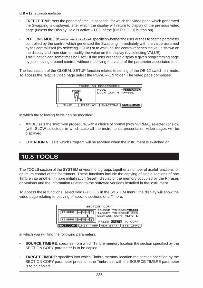
OB 12 Z-Domain Synthesizer
10.8 TOOLS
236
• FREEZE TIME: sets the period of time, in seconds, for which the video page which generatedthe Swapping is displayed, after which the display will return to display of the previous videopage (unless the Display Hold is active – LED of the [DISP HOLD] button on).
• POT. LINK MODE (Potentiometer Link Mode): specifies whether the user wishes to set the parametercontrolled by the control which generated the Swapping immediately with the value assumedby the control itself (by selecting HOOK) or to wait until the control reaches the value shown onthe display and then start to modify the value on the display (by selecting VALUE).This function can sometimes be useful if the user wishes to display a given programming pageby just moving a panel control, without modifying the value of the parameter associated to it.
The last section of the GLOBAL SETUP function relates to setting of the OB-12 switch-on mode.To access the relative video page select the POWER-ON folder. The video page comprises:
in which the following fields can be modified:
• MODE: sets the switch-on procedure, with a choice of normal (with NORMAL selected) or slow(with SLOW selected), in which case all the instrument’s presentation video pages will bedisplayed.
• LOCATION N. : sets which Program will be recalled when the instrument is switched on.
The TOOLS section of the SYSTEM environment groups together a number of useful functions foroptimum control of the instrument. These functions include the copying of single sections of oneTimbre into another, Timbre initialisation (reset), display of the memory occupied by the Phrasesor Motions and the information relating to the software versions installed in the instrument.
To access these functions, select field 8-TOOLS in the SYSTEM menu; the display will show thevideo page relating to copying of specific sections of a Timbre:
in which you will find the following parameters:
• SOURCE TIMBRE: specifies from which Timbre memory location the section specified by theSECTION COPY parameter is to be copied.
• TARGET TIMBRE: specifies into which Timbre memory location the section specified by theSECTION COPY parameter present in the Timbre set with the SOURCE TIMBRE parameteris to be copied.
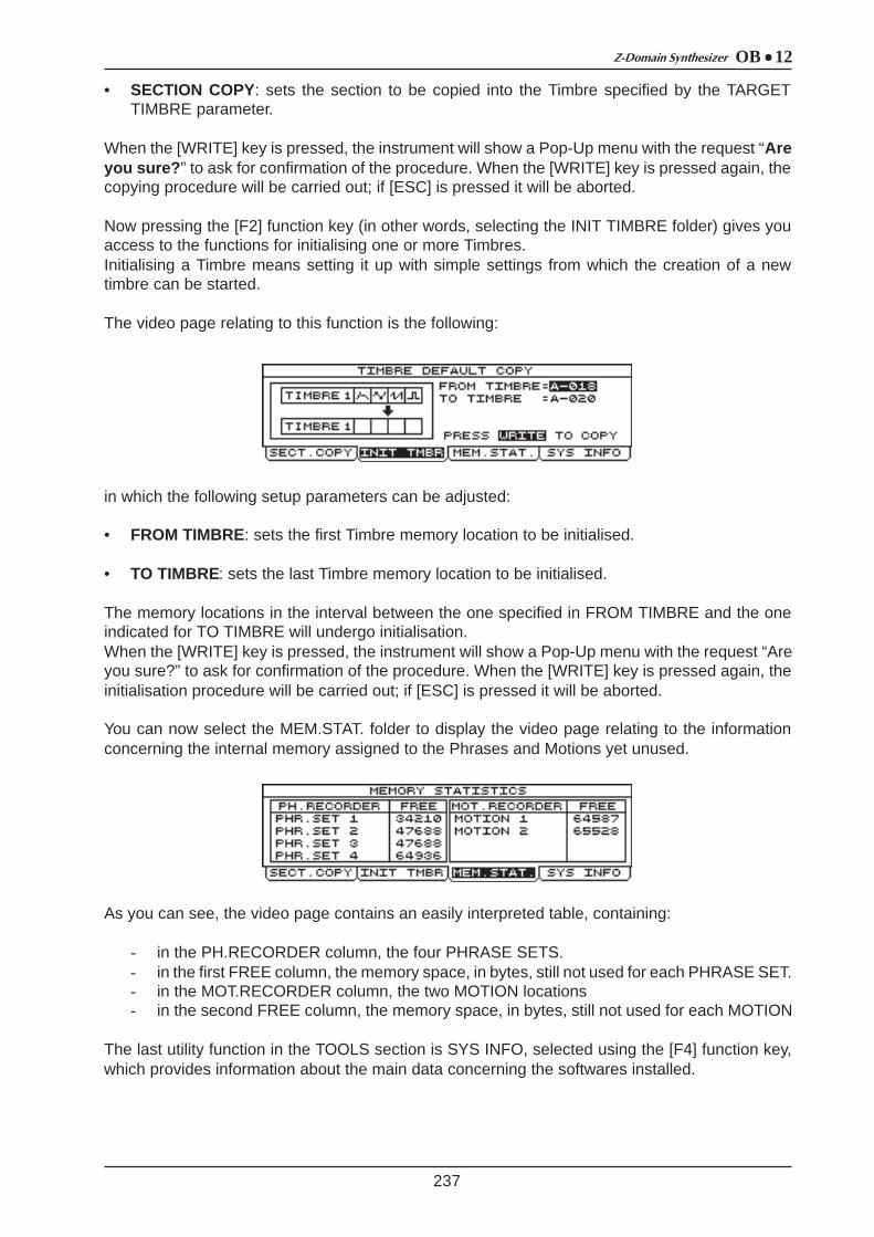
OB 12Z-Domain Synthesizer
237
• SECTION COPY: sets the section to be copied into the Timbre specified by the TARGETTIMBRE parameter.
When the [WRITE] key is pressed, the instrument will show a Pop-Up menu with the request “Areyou sure? ” to ask for confirmation of the procedure. When the [WRITE] key is pressed again, thecopying procedure will be carried out; if [ESC] is pressed it will be aborted.
Now pressing the [F2] function key (in other words, selecting the INIT TIMBRE folder) gives youaccess to the functions for initialising one or more Timbres.Initialising a Timbre means setting it up with simple settings from which the creation of a newtimbre can be started.
The video page relating to this function is the following:
in which the following setup parameters can be adjusted:
• FROM TIMBRE: sets the first Timbre memory location to be initialised.
• TO TIMBRE: sets the last Timbre memory location to be initialised.
The memory locations in the interval between the one specified in FROM TIMBRE and the oneindicated for TO TIMBRE will undergo initialisation.When the [WRITE] key is pressed, the instrument will show a Pop-Up menu with the request “Areyou sure?” to ask for confirmation of the procedure. When the [WRITE] key is pressed again, theinitialisation procedure will be carried out; if [ESC] is pressed it will be aborted.
You can now select the MEM.STAT. folder to display the video page relating to the informationconcerning the internal memory assigned to the Phrases and Motions yet unused.
As you can see, the video page contains an easily interpreted table, containing:
- in the PH.RECORDER column, the four PHRASE SETS.- in the first FREE column, the memory space, in bytes, still not used for each PHRASE SET.- in the MOT.RECORDER column, the two MOTION locations- in the second FREE column, the memory space, in bytes, still not used for each MOTION
The last utility function in the TOOLS section is SYS INFO, selected using the [F4] function key,which provides information about the main data concerning the softwares installed.

OB 12 Z-Domain Synthesizer
238
displaying the following information:
• CPU REL.: displays the release version of the CPU software currently installed in the instrument.
• DATE: displays the date of creation of the CPU software release.
• DSP REL.: displays the release version of the DSP software currently installed in the instrument.
• DATE: displays the date of creation of the DSP software release.
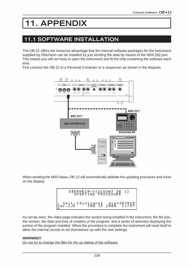
OB 12Z-Domain Synthesizer
11. APPENDIX
11.1 SOFTWARE INSTALLATION
239
The OB-12 offers the immense advantage that the internal software packages for the instrumentsupplied by Oberheim can be installed by just sending the data by means of the MIDI [IN] port.This means you will not have to open the instrument and fit the chip containing the software eachtime.First connect the OB-12 to a Personal Computer or a sequencer as shown in the diagram.
When sending the MIDI datas, OB-12 will automatically abilitate the updating procedure and showon the display:
As can be seen, the video page indicates the section being installed in the instrument, the file size,the version, the date and time of creation of the program, and a series of asterisks displaying theportion of the program installed. When the procedure is complete the instrument will reset itself toallow the internal circuits to set themselves up with the new settings.
WARNING!!Do not try to change the files for the up dating of the software.

OB 12 Z-Domain Synthesizer
11.2 ERROR MESSAGES
CRC ERROR
It occured an error in the installation of the software up-date (error in reading the datas, transmissioninterruption, etc...). Swithc off the instrument and start the installation procedure (see par. 11.1).
DATA LOSS DETECTED – PROGRAM
There is a loss Program datas (by switching the instrument off during the memorization). Thescreen displays the unusable Program datas (compared to the maximun number) and one in thecheck phase. The unusuable Program will be replaced by default Program.
DATA LOSS DETECTED – TIMBRE
There is a loss Timbre datas (by switching the instrument off during the memorization). The screendisplays the unusable Timbre datas (compared to the maximun number) and one in the checkphase. The unusuable timbres will be replaced by INIT TIMBRE.
240
If the first software installation has not succeeded (because for ex. of transmission faults), theinstrument cannot be switch on in the normal way as in such a case the internal memory contentis not the correct one.In such a case please proceed with the updating procedure manually by pressing button [ESC]when you switch it on. The display will show “Waiting for MIDI Data ” and will wait for the MIDImessages concerning the software that has to be installed.

OB 12Z-Domain Synthesizer
11.3 MIDI
241
WHAT MIDI IS
The MIDI (Musical Instrument Digital Interface) allows instruments of different makes and types tocommunicate with each other by means of this clearly specified protocol of codes.This makes it possible to create systems of MIDI instruments offering much greater versatility andcontrol than would be possible with isolated instruments.To make this communication possible, all MIDI instruments have two or three 5-pin DIN connectorscalled:
- MIDI IN: Connector by means of which the device receives the MIDI data emitted by otherunits.
- MIDI OUT: Connector by means of which the device transmits the MIDI data it has generatedto other units.
- MIDI THRU: This connector, used to connect several units in series, emits the MIDI data exactlyas received by the respective MIDI IN port.
For example, most instruments equipped with MIDI interface transmit MIDI messages which specifywhich note has been played and with what dynamic through the MIDI OUT connector. If thisconnector is connected to the MIDI IN of another MIDI instrument, such as a synthesizer or anexpander, this device will respond precisely to the notes played on the transmitter instrument. Thisallows in you in effect to play two instruments at once, and obtain special multi-instrument sounds.
The same type of information transfer is used for recording MIDI sequences. A PC or a sequencercan be used to record the MIDI data transmitted by the OB-12 or by any other instrument. Whenthese recorded data are sent to the OB-12, it automatically plays back the recorded performance.
CAUTION! Always use cables of the best quality for the MIDI connections to and from the OB-12. You are alsoadvised never to use cables more than 5 metres long.
MIDI Channels
MIDI is able to transmit a multitude of digital data by means of a single cable and therefore a singleconnector, thanks to the MIDI channels. There are 16 MIDI channels, so the MIDI messages areprocessed when the channels of the receiver and transmitter devices correspond. The OB-12 isable to receive and transmit information on one or four MIDI channels simultaneously (see point10.1).
Main MIDI messages transmitted and received by the OB-12
MIDI includes various types of messages used to communicate various types of data. MIDImessages can be subdivided into messages managed separately on each channel and messagesdedicated to the entire system.
The channel messages include:
• Note On: this message is transmitted when a note is played, i.e. when a keyboard key ispressed. Each Note On message includes the following codes:Note On: when a key was pressed;Note Number: the key and thus the relative note which has been played;Velocity: dynamic of the note (the force with which the key was pressed).Note messages are expressed as a number from 0 to 127, with Middle C represented by thenumber 60.

OB 12 Z-Domain Synthesizer
242
• Note Off: this message is transmitted when the key pressed previously is released. When it isreceived, the sound of the note of that key is deactivated. Each Note Off message includes thefollowing codes:Note Off: a key has been released;Note Number: which key has been released;Velocity: dynamic (force) with which it has been released.
N.B.: The Note On message with Velocity=0 is considered as equivalent to a Note Off message. The OB-12sends the Note On message with Velocity=0.
• Pitch Bend: this message indicates the position assumed by the [PITCH] wheel.• Aftertouch: this message transmits the value of the pressure applied to a key after it has been
depressed. There are two types of Aftertouch messages: the channel Aftertouch, which transmitsthe value of this control regardless of the test pressed, and polyphonic Aftertouch which specifiesthe key to which the pressure has been applied.
• Program Change: this message is used to select programs, since many instruments have alarge number of memories, each corresponding to a given program or timbre. Once thecorrespondence between the number assigned to the memory and the Program Change numberis known, you can select the type of sound you require.
• Control Change: these are control messages (often associated to the sliders or pedals) usedto add expressiveness to the performance, allowing definition (and if required real-time control)of the timbre parameters, including for example the volume (CC n.7) or the Portamento time(CC n.5), etc...The Control Change messages also include the NRPN (Non Registered Parameter Numbers)LSB and MSB, which specify which control on the OB-12 panel has been regulated, and theData Entry LSB message specifying the value it has assumed.
The system messages are subdivided into three categories: System Common Messages, SystemReal Time Messages and System Exclusive Messages. Of these categories, the OB-12 does nothandle the System Common Messages.
The System Real Time Messages comprise:
• Clock: a MIDI message used to synchronise MIDI instruments connected together. Thismessage is sent 24 times for each crotchet.
• Start: message used to position the MIDI instrument at the beginning of a song (or a Phraseas in the OB-12) and start playback or recording.
• Continue: this message allows the playback/recording to be restarted from the bar after thelast Stop carried out.
• Stop: this message interrupts the playback/recording.• Active Sensing: this message is transmitted to keep the dialogue between the connected
MIDI devices active and is sent every 300 msec. if no other MIDI messages are transmitted. Ifa MIDI instrument does not receive MIDI messages or a fresh Active Sensing after 300 msec.it deactivates its functions and signals a “MIDI Error”, supposing that the connection has beeninterrupted or the connected device has been switched off.
System Exclusive Messages are those instructions which can only be interpreted by device identicalto the one which generated them. These messages include the BULK DUMP data, i.e. the device’sprogramming instructions. These instructions contain the programming parameters normally savedin a memory location. They are used to transfer these parameters from one device to another ofsimilar kind, or to save them in a remote memorisation unit such as a computer or a sequencer,allowing them to be restored in case of accidental loss or cancellation. Another system exclusivemessage is the one used to identify the transmitter instrument if the receiver instrument requeststhis.

OB 12Z-Domain Synthesizer
11.4 BLOCK DIAGRAM
243

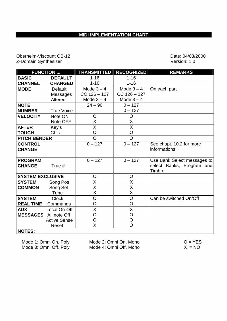
MIDI IMPLEMENTATION CHART
Oberheim-Viscount OB-12 Date: 04/03/2000 Z-Domain Synthesizer Version: 1.0
FUNCTION ... TRANSMITTED RECOGNIZED REMARKS
BASIC DEFAULT CHANNEL CHANGED
1-16 1-16
1-16 1-16
MODE Default Messages Altered
Mode 3 – 4 CC 126 – 127
Mode 3 – 4
Mode 3 – 4 CC 126 – 127
Mode 3 – 4
On each part
NOTE NUMBER True Voice
24 – 96 0 – 127 0 – 127
VELOCITY Note ON Note OFF
O X
O X
AFTER Key’s TOUCH Ch’s
X O
X O
PITCH BENDER O O CONTROL CHANGE
0 – 127
0 – 127 See chapt. 10.2 for more informations
PROGRAM CHANGE True #
0 – 127 0 – 127 Use Bank Select messages to select Banks, Program and Timbre
SYSTEM EXCLUSIVE O O SYSTEM Song Pos COMMON Song Sel Tune
X X X
X X X
SYSTEM Clock REAL TIME Commands
O O
O O
Can be switched On/Off
AUX Local On-Off MESSAGES All note Off Active Sense Reset
X O O X
X O O O
NOTES: Mode 1: Omni On, Poly Mode 2: Omni On, Mono O = YES Mode 3: Omni Off, Poly Mode 4: Omni Off, Mono X = NO
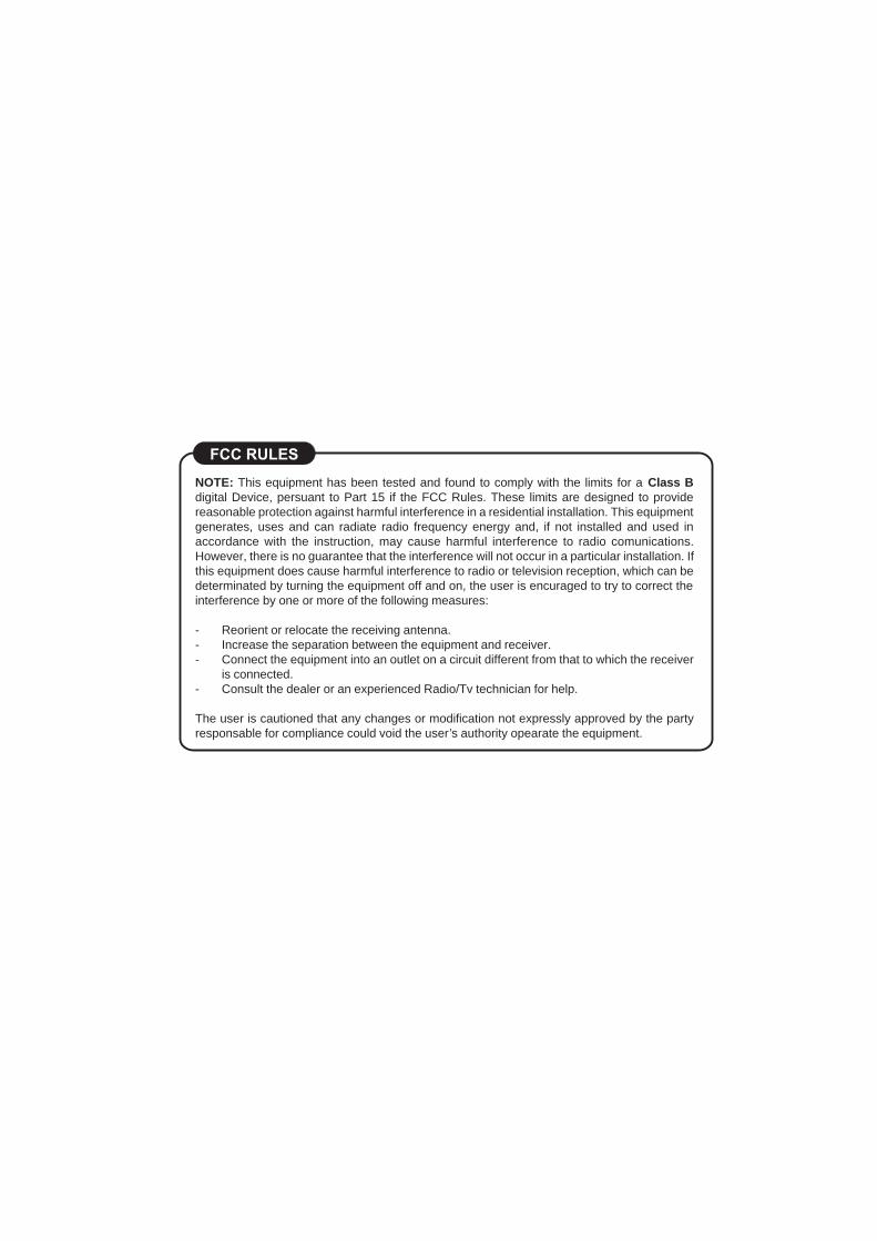
NOTE: This equipment has been tested and found to comply with the limits for a Class Bdigital Device, persuant to Part 15 if the FCC Rules. These limits are designed to providereasonable protection against harmful interference in a residential installation. This equipmentgenerates, uses and can radiate radio frequency energy and, if not installed and used inaccordance with the instruction, may cause harmful interference to radio comunications.However, there is no guarantee that the interference will not occur in a particular installation. Ifthis equipment does cause harmful interference to radio or television reception, which can bedeterminated by turning the equipment off and on, the user is encuraged to try to correct theinterference by one or more of the following measures:
- Reorient or relocate the receiving antenna.- Increase the separation between the equipment and receiver.- Connect the equipment into an outlet on a circuit different from that to which the receiver
is connected.- Consult the dealer or an experienced Radio/Tv technician for help.
The user is cautioned that any changes or modification not expressly approved by the partyresponsable for compliance could void the user’s authority opearate the equipment.