OAMP (EMS and SEM) Integration Guide · Figure 2-1: EMS - NMS Integration . OAMP Integration Guide...
70
AudioCodes™ Element Management System (EMS) and Session Experience Manager (SEM) OAMP (EMS and SEM) Integration Guide Version 6.8
-
Upload
trinhnguyet -
Category
Documents
-
view
232 -
download
0
Transcript of OAMP (EMS and SEM) Integration Guide · Figure 2-1: EMS - NMS Integration . OAMP Integration Guide...

AudioCodes™ Element Management System (EMS) and Session Experience Manager (SEM)
OAMP (EMS and SEM) Integration Guide Version 6.8


OAMP Integration Guide Contents
Version 6.8 3 April 2014
Table of Contents
1 About the AudioCodes Element Management System (EMS) ......................... 9
2 OAMP Integration Concepts ............................................................................. 11
2.1 Overview ................................................................................................... 11 2.1.1 Integration Options Summary ................................................................. 13
2.1.1.1 Single Login ..................................................................................... 13 2.1.1.2 EMS Topology File ........................................................................... 13 2.1.1.3 Alarms ............................................................................................. 13 2.1.1.4 GW Status ....................................................................................... 13 2.1.1.5 Performance Monitoring Metrics ....................................................... 13 2.1.1.6 Security ............................................................................................ 14
2.2 Client (GUI) Integration ........................................................................... 15 2.2.1 JAWS URL Browsing.............................................................................. 16 2.2.2 Command Line Interface – CLI Northbound Interface ............................ 17
2.2.2.1 JAVA EMS API Northbound Interface ............................................... 19 2.2.2.2 Enabling Log-in from an NMS Client to a Single EMS Client ............. 19
2.3 EMS Server Access ................................................................................. 22 2.4 Topology File ........................................................................................... 24 2.5 Faults (Alarms and Events) .................................................................... 27
2.5.1 Alarms and Events Reception in the NMS .............................................. 27 2.5.1.1 MG and EMS Alarms Forwarding by the EMS Application ................ 28 2.5.1.2 Each Media Gateway Forwards its Alarms Directly to the NMS ......... 31
2.5.2 Alarms Clearing Mechanism ................................................................... 36 2.5.3 Alarms Sequence Numbering ................................................................. 37 2.5.4 Alarms Synchronization via MG SNMP I/F ............................................. 38
2.6 Status / State Management via MG SNMP I/F ........................................ 40 2.7 Provisioning and Maintenance ............................................................... 40 2.8 Performance Monitoring ......................................................................... 41
2.8.1 EMS Server CSV / XML File Format Interface ........................................ 43 2.8.1.1 CSV File Format............................................................................... 44 2.8.1.2 XML File Format............................................................................... 45
2.8.2 Mediant 5000 and Mediant 8000 CSV File Format Interface ................... 46 2.8.3 Media Gateway SNMP Interface ............................................................ 46 2.8.4 Mediant 5000 and Mediant 8000 Performance Thresholds ..................... 47
2.9 Security Aspects ..................................................................................... 48 2.9.1 EMS Users Management (Authentication and Authorization) ................. 48
2.9.1.1 Authentication and Authorization using a Radius Server ................... 49 2.9.1.2 Authentication and Authorization using a TACACS+ Server .............. 52 2.9.1.3 Authentication and Authorization using an LDAP Server ................... 57
2.9.2 Network Communication Protocols ......................................................... 58
3 EMS Private Labeling ........................................................................................ 59
3.1 Overview ................................................................................................... 59 3.2 Private Labeling Procedure .................................................................... 59
3.2.1 Creating a New Customer Specific EMS DVD ........................................ 59 3.2.2 Custom ZIP file ....................................................................................... 60
3.2.2.1 Overview .......................................................................................... 60 3.2.2.2 Images Folder .................................................................................. 61 3.2.2.3 localeProperties Folder..................................................................... 61

EMS and SEM
OAMP Integration Guide 4 Document #: LTRT-19212
3.2.2.4 ProductNames Folder ...................................................................... 62 3.2.2.5 Online Help Folder ........................................................................... 63
3.2.3 EMS Server Full Branding Process ........................................................ 64
A Appendix – Private Labeling Icons .................................................................. 69

OAMP Integration Guide Contents
Version 6.8 5 April 2014
List of Figures
Figure 2-1: EMS - NMS Integration.................................................................................................... 12 Figure 2-2: ‘Welcome to EMS CLI’ Prompt ........................................................................................ 17 Figure 2-3: Log-in from NMS Client to a single EMS Client: 'Login Successful' in Prompt ................... 19 Figure 2-4: Example MediaPack Status screen ................................................................................. 20 Figure 2-5: Switching to Another (Single) EMS Client ........................................................................ 20 Figure 2-6: Example MediaPack Status screen after Switching .......................................................... 21 Figure 2-7: Choose a Digital Certificate ............................................................................................. 22 Figure 2-8: NBIF Parent Directory ..................................................................................................... 23 Figure 2-9: NBIF Topology Directory ................................................................................................. 23 Figure 2-10: Topology File-Excel View .............................................................................................. 25 Figure 2-11: Topology File: Notepad View ......................................................................................... 26 Figure 2-12: Faults (Alarms) .............................................................................................................. 28 Figure 2-13: Traps Forwarding Configuration .................................................................................... 29 Figure 2-14: SNMP Trap Forwarding ................................................................................................. 30 Figure 2-15: Destination Rule Configuration ...................................................................................... 32 Figure 2-16: Add New SNMPv3 User Dialog ..................................................................................... 35 Figure 2-17: Performance Monitoring - Intervals ................................................................................ 41 Figure 2-18: Performance Monitoring ............................................................................................... 42 Figure 2-19: Background Monitoring csv File ..................................................................................... 44 Figure 2-20: xml File Header Example .............................................................................................. 45 Figure 2-21: xml File Data Example................................................................................................... 45 Figure 2-22: EMS Users-External Authentication and Authorization ................................................... 48 Figure 2-23: Authentication and Authorization Setting-RADIUS ......................................................... 51 Figure 2-24: Authentication and Authorization Settings-TACACS+..................................................... 55 Figure 2-25: LDAP Authentication and Authorization ......................................................................... 57 Figure 3-1: Custom ZIP File .............................................................................................................. 60

EMS and SEM
OAMP Integration Guide 6 Document #: LTRT-19212
Reader's Notes

OAMP Integration Guide Notices
Version 6.8 7 April 2014
Notice
This guide shows how OAMP (Operation, Administration,Maintenance and Provisioning) is integrated with the EMS and SEM.
Information contained in this document is believed to be accurate and reliable at the time of printing. However, due to ongoing product improvements and revisions, AudioCodes cannot guarantee accuracy of printed material after the Date Published nor can it accept responsibility for errors or omissions. Updates to this document and other documents including the most updated SW releases can be viewed by registered customers http://www.audiocodes.com/downloads.
© 2014 AudioCodes Inc. All rights reserved
This document is subject to change without notice.
Date Published: April-22-2014
Trademarks
AudioCodes, AC, AudioCoded, Ardito, CTI2, CTI², CTI Squared, HD VoIP, HD VoIP Sounds Better, InTouch, IPmedia, Mediant, MediaPack, NetCoder, Netrake, Nuera, Open Solutions Network, OSN, Stretto, TrunkPack, VMAS, VoicePacketizer, VoIPerfect, VoIPerfectHD, What’s Inside Matters, Your Gateway To VoIP and 3GX are trademarks or registered trademarks of AudioCodes Limited. All other products or trademarks are property of their respective owners.
WEEE EU Directive
Pursuant to the WEEE EU Directive, electronic and electrical waste must not be disposed of with unsorted waste. Please contact your local recycling authority for disposal of this product.
Customer Support
Customer technical support and services are provided by AudioCodes or by an authorized AudioCodes Service Partner. For more information on how to buy technical support for AudioCodes products and for contact information, please visit our Web site at www.audiocodes.com/support.
Documentation Feedback
AudioCodes continually strives to produce high quality documentation. If you have any comments (suggestions or errors) regarding this document, please fill out the Documentation Feedback form on our Web site at http://www.audiocodes.com/downloads.

EMS and SEM
OAMP Integration Guide 8 Document #: LTRT-19212
Manual Name
Mediant 500 MSBR SIP User's Manual
Mediant 500 E-SBC SIP User's Manual
Mediant 600 and 1000 SIP User’s Manual
Mediant 800B Gateway and E-SBC User’s Manual
Mediant 800B MSBR SIP User’s Manual
Mediant 1000B Gateway and E-SBC User’s Manual
Mediant 1000B MSBR SIP User’s Manual
Mediant 2000 User’s Manual
Mediant 2600 E-SBC User's Manual
Mediant 3000 User’s Manual
Mediant Software E-SBC User's Manual
Mediant 2000 SBA Quick Guide
Mediant 1000 SBA Quick Guide
Mediant 800 SBA Quick Guide
MediaPack User’s Manual
Element Management System (EMS) Server Installation, Operation and Maintenance Manual
Element Management System (EMS) Product Description
Element Management System (EMS) OAMP Integration Guide
Element Management System (EMS) User’s Manual
Element Management System (EMS) Online Help
Mediant 5000 / 8000 Media Gateway Installation, Operation and Maintenance Manual
Mediant 5000 / 8000 Media Gateway Release Notes
Mediant 5000 / 8000 Media Gateway Programmer's User Manual
Mediant 3000 TP-8410 OAM Guide
Mediant 3000 TP-6310 OAM Guide
Mediant 2000 OAM Guide
Mediant 1000 E-SBC OAM Guide
Mediant 1000 MSBG OAM Guide
Mediant 800 E-SBC OAM Guide
Mediant 800 MSBG OAM Guide
Mediant 600 OAM Guide

OAMP Integration Guide 1. About the AudioCodes Element Management System (EMS)
Version 6.8 9 April 2014
1 About the AudioCodes Element Management System (EMS) The EMS is an advanced solution for standards-based management of Media Gateways within VoIP networks, covering all areas that are vital for the efficient operation, administration, management and provisioning (OAMP) of the AudioCodes' family of Media Gateways. The products managed by the EMS include, the digital Mediant Series VoIP Media Gatewayss the analog MediaPack Series VoIP Media Gateways and the Software-based gateways. AudioCodes EMS provides a full control and management solution for these products. The EMS enables Network Equipment Providers (NEPs) and System Integrators (SIs) the ability to offer customers rapid time-to-market and inclusive, cost-effective management of next-generation networks. The standards-compliant EMS for Media Gateways uses distributed SNMP-based management software, optimized to support day-to-day Network Operation Center (NOC) activities, offering a feature-rich management framework. It supports fault management, configuration and security. This document describes two integral OEM customization features:
How to integrate the product management into existing management architecture (NMS/OSS)
How to perform product private labeling

EMS and SEM
OAMP Integration Guide 10 Document #: LTRT-19212
Reader’s Notes
OAMP Integration Guide 2. OAMP Integration Concepts
Version 6.8 11 April 2014
2 OAMP Integration Concepts 2.1 Overview
The main purpose of the EMS is to provide an easy-to-use human interface to provision and maintain AudioCodes’ Media Gateways. The intuitive implementation of the EMS seeks to prevent human error in Media Gateway configuration. This is essential for the maintainance of a highly available solution. Development of the EMS is closely correlated with the development of the Media Gateways. Every new Media Gateway software version requires that the EMS is correspondingly updated. Using the EMS allows customers to upgrade the software in the Media Gateways as soon it becomes available, without waiting for the development on the management system. In summary, the EMS is in AudioCodes’ assessment, the best tool to manage AudioCodes Media Gateways. However, it does not , replace the NMS and OSS management systems, which displays to operators a comprehensive view of the network (including other vendors’ equipment). After defining and initially provisioning a Media Gateway via the EMS, operators will usually work with an NMS / OSS for day-to-day maintenance. Only in the event of problemswith a Media Gateway or when provisioning or maintenance tasks must be performed, will operators open the EMS and work directly with it. Therefore, we developed the proposed APIs for Single Login, faults (alarms), performance monitoring and security integration with a higher level management system (described in this document).
Figure 2-1 on page 12 shows how the EMS client (a Windows™ based Java™ 1.6 application running on the operator’s PC) and EMS server (Linux based server machine with CentOS 5.3 operating system and utilizing an Oracle™ 11g Standard Edition Database) are integrated with a Network Management System (NMS)1.
1 The same applies to a higher-level OSS (Operations Support System).

EMS and SEM
OAMP Integration Guide 12 Document #: LTRT-19212
Figure 2-1: EMS - NMS Integration

OAMP Integration Guide 2. OAMP Integration Concepts
Version 6.8 13 April 2014
2.1.1 Integration Options Summary
2.1.1.1 Single Login The EMS client implements an EMS CLI API northbound interface which enables an NMS client station to browse an EMS client GUI in a Media Gateway context.To enable a single login between the NMS and EMS applications, the EMS client must be installed on the same machine as the NMS client . Thereafter, the NMS application can launch the EMS client application when the operator runs the file cli.exe located in the EMS client installation directory The EMS client login definitions are set in the EMS CLI API (Command Line Interface). For more information, see Section 2.2.2 on page 17.
2.1.1.2 EMS Topology File The EMS Topology file includes a snapshot of all the gateways defined in the EMS application. It is found on the EMS server and is available for the higher level management system. For more information, see Section 2.4 on page 24.
2.1.1.3 Alarms Alarms are sent from Media Gateways and EMS as SNMP notifications (traps). These traps can be either of the following:
Forwarded by the EMS application to the NMS server (for all the network elements and the EMS itself).
Sent by each one of the network elements directly to the NMS server. In this case, there is the possibility to enable EMS Alarms. For example, when a connection between the EMS server and a Media Gateway is established or lost, traps are forwarded to the NMS server machine.
2.1.1.4 GW Status The status of a gateway can be determined based on the set of supported IETF Management Information Base (MIB-II) tables( described in Section 2.6 on page 40).
2.1.1.5 Performance Monitoring Metrics Performance Monitoring (PM) data and statistics are made available to the NMS using either of the following methods:
Collection of csv or xml files fom the EMS server machine via FTP or SFTP. EMS performs SNMP polling of the network elements and creates a summary file per element or per collection interval.
Collection of information directly from the network element via the SNMP interface.

EMS and SEM
OAMP Integration Guide 14 Document #: LTRT-19212
2.1.1.6 Security Security integration covers two main areas: Users Management and Network Communication protocols.
EMS Users Management (Authentication and Authorization): locally in the EMS database via a centralized Radius server or TACACS server.
Network Communication Protocols:
• EMS Client-Server communication is secured using RMI (Remote Method Invocation) protocol over SSL (Secure Sockets Layer). EMS also enables client installation and launching via JAWS running over HTTPS.
• The connection between the EMS server and the gateway can be secured as follows: ♦ Mediant 5000 / Mediant 8000:
SNMPv3 for Provisioning, Maintenance Action, Faults and Performance Monitoring.
SSH and SCP for File transfer and Online Sotwware Upgrade. IPsec IKE pre-shared key for other communication (such as NTP).
♦ CPE's: SNMPv3 for Provisioning, Maintenance Action, Faults and
Performance Monitoring. HTTPS for File transfer and Online Sotware Upgrade. IPsec IKE pre-shared key for other communication (like NTP).
The connection between the EMS server and the NMS server is optionally secured over IPsec with a IKE pre-shared key. In addition, it is recommended to use SSH and SFTP.

OAMP Integration Guide 2. OAMP Integration Concepts
Version 6.8 15 April 2014
2.2 Client (GUI) Integration The EMS client is a Java™ application running on a Windows™ operating system. It can be installed on the Desktop either from DVD, or via Web interface by running Java Web Start (JAWS) from the EMS server machine. Use one of the following options to perform integration for the purpose of a single login:
JAWS URL browsing with appropriate parameters
Command Line Interface – CLI (applicable for Desktop clients integration)
JAVA EMS API Northbound Interface
All the above options can be run together with other management systems clients, such as an NMS / OSS. In this way, the NMS /OSS can pop up the EMS client when the AudioCodes Media Gateway icon is selected. This allows operators to browse through the various management systems without moving from their desks. The drill-down feature is possible through popping up the EMS client. All the above three options provide the following additional features:
Single login: When opening the EMS client, the login screen is skipped if the user name and password are provided through the CLI.
Select the Media Gateway: If switch –I is defined in the CLI, the status screen of this specific Media Gateway (whose IP address was defined) is displayed in the EMS client GUI on opening.
Enable/disable navigation tree: If a specific operator is not allowed to view any other Media Gateways, the navigation tree can be hidden so that the operatoraccess other Media Gateways.
Enable/disable active alarms browser view: The active alarms pane can be hidden from the EMS screen, which forces operators to use the NMS / OSS alarm browser.

EMS and SEM
OAMP Integration Guide 16 Document #: LTRT-19212
2.2.1 JAWS URL Browsing This section describes JAWS URL browsing.
To run the EMS client after JAWS install via the following URL:
https://<server_ip>/jaws - it will open a regular 'EMS Login Screen'. For example:
http://10.7.6.18/jaws/
https://<server_ip>/jaws/?username=<user_name>&password=<password>.
For example:
http://10.7.6.18/jaws/?username=acladmin&password=pass_12345
https://<server_ip>/jaws/?username=<user_name>&password=<password>&showtree=<false>&showalarmbrowser=<false>&nodeip=<node ip> where each one of the supported arguments can be provided in any order. Upon client opening, the user can change initial settings of his view by editing 'View' menu items.
Supported arguments are as follows:
username - must include the username
password - must include clear text password
(Optional) nodeip - when requested, the EMS client opens to the requested node status screen. Default - globe view on the status screen.
(Optional) showtree – supported values: true(default)/false.
(Optional) showalarmbrowser – supported values : true(default)/false.
For example:
http://10.7.6.18/jaws/?username=acladmin&password=pass_12345&challenge=nomatter&showtree=false&showalarmbrowser=false&nodeip=10.7.5.201

OAMP Integration Guide 2. OAMP Integration Concepts
Version 6.8 17 April 2014
2.2.2 Command Line Interface – CLI Northbound Interface The EMS features a EMS CLI API Northbound Interface (Command Line Interface) that enables operators to log in from an NMS client to a single EMS client. After the EMS client is installed, operators can access the folder ‘Nbif’ located under the client directory (Program Files > EMS Client). The folder 'Nbif' includes the following important files:
nbif.jar (this file is the EMS CLI Northbound Interface; see Section 2.2.2 on page 21.
NbIf.html (this file includes API information that programmers must know to connect to the CLI).
To run the CLI:
In the EMS client installation directory (on yourcomputer), double-click file 'cli.exe'; the prompt 'Welcome to EMS CLI' is displayed.
Figure 2-2: ‘Welcome to EMS CLI’ Prompt
Th

EMS and SEM
OAMP Integration Guide 18 Document #: LTRT-19212
The table below describes the EMS CLI commands.
EMS CLI Switch Description
-L Language locale. Default en_US
-I Node IP to display upon mounting EMS main frame
-T True/false whether to show tree node in the EMS main frame (Default-true)
-A True/false whether to show alarm browser in the EMS main frame
-H Shows this help

OAMP Integration Guide 2. OAMP Integration Concepts
Version 6.8 19 April 2014
2.2.2.1 JAVA EMS API Northbound Interface Add the following .jar files to your Java™ application:
nbif.jar (Nbif folder)
client.jar
jbcl.jar
Externals (client installation folder)
For a detailed description of the EMS CLI API, open the file Nbif.html located in the folder ‘Nbif’ located in the client directory ('Program Files > EMS Client').
2.2.2.2 Enabling Log-in from an NMS Client to a Single EMS Client This section describes how to enable log-in from an NMS client to a single EMS client.
To enable a log-in from an NMS client to a single EMS client:
1. Follow the format displayed in the 'Welcome to EMS CLI' prompt (see Section 2.2.2 on page 17 and enter text similar to the following :
cli> nmsLogin admin admin 10.7.8.23 -I10.7.5.216 -Tfalse –Afalse
2. Press Enter to execute this command; 'Login successfully' is displayed (shown below) and the EMS client connection to server "10.7.8.23" with username 'admin', password 'admin' is opened (shown below). The EMS client refers to the Media Gateway with IP address "10.7.5.216". It’s MGs Tree and Alarm Browser cannot be displayed:
Figure 2-3: Log-in from NMS Client to a single EMS Client: 'Login Successful' in Prompt

EMS and SEM
OAMP Integration Guide 20 Document #: LTRT-19212
Figure 2-4: Example MediaPack Status screen
To switch to another (single) EMS client:
1. In the cli> command line in the prompt adjacent to changeToNode, type the IP address of the EMS client to which you wish to switch (see the figure below). (Example: cli> changeToNodeIP 10.7.19.98)
Figure 2-5: Switching to Another (Single) EMS Client
2. Press Enter; the command is executed and the EMS switches to the Media Gateway with the IP address 10.7.19.98 (see the figure below).

OAMP Integration Guide 2. OAMP Integration Concepts
Version 6.8 21 April 2014
Figure 2-6: Example MediaPack Status screen after Switching

EMS and SEM
OAMP Integration Guide 22 Document #: LTRT-19212
2.3 EMS Server Access All EMS and gateway information available for the NMS and other Northbound interfaces including Topology, Performance and Backup data is located in the EMS server machine under the folder /ACEMS/NBIF. This folder can be accessed using HTTPS browsing by entering the URL https://<EMS Server IP>/NBIF in your Web Browser. Note, that the customer’s Web browser must have the appropriate X.509 certificates signed by the same Certificate Authority (CA) as the EMS server web browser certificates. Choose the appropriate certificate, and then click OK.
Figure 2-7: Choose a Digital Certificate
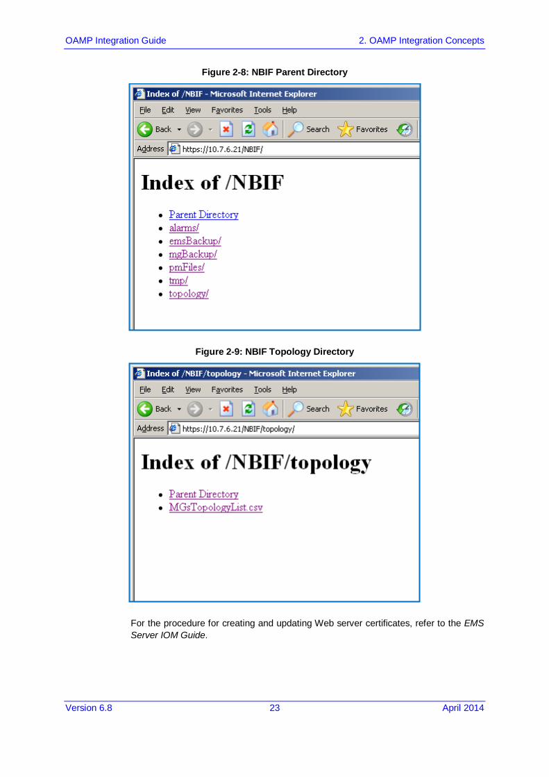
The 'NBIF' folder content opens; double-click each one of the folders to list it’s contents. Double-click each one of the files to open it.
OAMP Integration Guide 2. OAMP Integration Concepts
Version 6.8 23 April 2014
Figure 2-8: NBIF Parent Directory
Figure 2-9: NBIF Topology Directory
For the procedure for creating and updating Web server certificates, refer to the EMS Server IOM Guide.
EMS and SEM
OAMP Integration Guide 24 Document #: LTRT-19212
EMS provides the following information in the 'NBIF' folder:
A Summary file of all the gateways and their basic properties defined in the EMS application. The summary file is located under the 'topology' folder and is always named MGsTopologyList. For more information on this file, see Section 2.4 on page 24.
Performance Monitoring files collected by EMS for all the defined and provisioned Gateways. These files are stored under the 'pmFiles' folder. For more information regarding the file naming convention, file structure and file management policy in this folder, see Section 2.8 on page 41.
EMS server, Mediant 5000 and Mediant 8000 backup files can be collected from the 'emsBackup' and 'mgBackup' folders. These files are usually collected via a central backup tool.
Alarms query result is located under the 'alarms'’ folder when the EMS user chose the 'Faults > Save Alarms As' alarms action in the client, and then the action result displayed more than 1500 records. This file is created for local user requests and must not be collected by higher level management or backup systems.
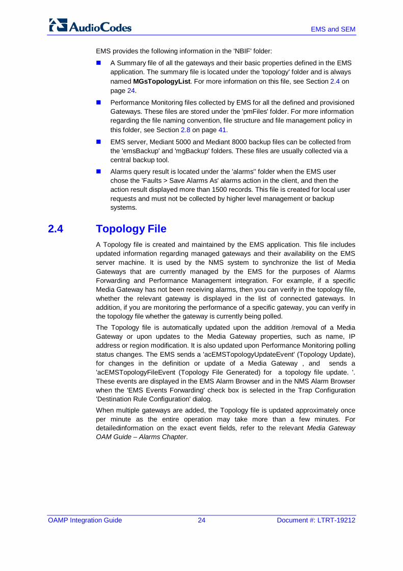
2.4 Topology File A Topology file is created and maintained by the EMS application. This file includes updated information regarding managed gateways and their availability on the EMS server machine. It is used by the NMS system to synchronize the list of Media Gateways that are currently managed by the EMS for the purposes of Alarms Forwarding and Performance Management integration. For example, if a specific Media Gateway has not been receiving alarms, then you can verify in the topology file, whether the relevant gateway is displayed in the list of connected gateways. In addition, if you are monitoring the performance of a specific gateway, you can verify in the topology file whether the gateway is currently being polled. The Topology file is automatically updated upon the addition /removal of a Media Gateway or upon updates to the Media Gateway properties, such as name, IP address or region modification. It is also updated upon Performance Monitoring polling status changes. The EMS sends a 'acEMSTopologyUpdateEvent' (Topology Update), for changes in the definition or update of a Media Gateway , and sends a 'acEMSTopologyFileEvent (Topology File Generated) for a topology file update. '. These events are displayed in the EMS Alarm Browser and in the NMS Alarm Browser when the 'EMS Events Forwarding' check box is selected in the Trap Configuration 'Destination Rule Configuration' dialog. When multiple gateways are added, the Topology file is updated approximately once per minute as the entire operation may take more than a few minutes. For detailedinformation on the exact event fields, refer to the relevant Media Gateway OAM Guide – Alarms Chapter.

OAMP Integration Guide 2. OAMP Integration Concepts
Version 6.8 25 April 2014
The Topology file 'MGsTopologyList.csv' is saved in the CSV format and is located under the 'ACEMS/NBIF/topology' folder on the EMS server machine. The file can be retrieved via the FTP or SFTP protocol, or read via Telnet or SSH using 'nbif' user. The file header is composed of two lines commencing with “;” : file format version, and column names. Each row in the file represents a Media Gateway in the EMS tree and includes the following information:
Serial Number (optional) for Mediant 5000 / Mediant 8000 Gateways will always be empty
IP Address – as provisioned by the user or auto detected
GATEWAY Name – as it appears in the EMS Tree
Region Name - as it appears in the EMS Tree
Product Type – e.g., Mediant 1000
Performance Polling Status – whether EMS is currently collecting (Polling) or GATEWAY history performance monitoring data.
Below are examples of Excel and Notepad file views:
Figure 2-10: Topology File-Excel View

EMS and SEM
OAMP Integration Guide 26 Document #: LTRT-19212
Figure 2-11: Topology File: Notepad View
Note: EMS Media Gateway report files can also be exported from the EMS application using the 'File > MGs Report' command. This file contains more information than the Topology report on the EMS server machine. The detailed file description can be found in the EMS User's Manual document. Both reports, received from the EMS client or the EMS server can be imported using the 'Add multiple MGs' command from the EMS Tree Region right-click option.

OAMP Integration Guide 2. OAMP Integration Concepts
Version 6.8 27 April 2014
2.5 Faults (Alarms and Events) The Media Gateway reports its faults (alarms and events) and state changes (Administrative/Operative state) via SNMP notification traps. Both standard and proprietary traps are supported. AudioCodes proprietary traps have the same variable bindings set. Each alarm includes information required by the ITU-T X.733 standard. Operative and Administrative states are managed according to the ITU-T X.731 standard. The 'Alarms' section in each one of the product OAM PGuides defines the exact list of standard, MG proprietary and EMS proprietary traps that are supported for each gateway product. For each trap description, there is an indication whether the trap is defined as an alarm or an event.
2.5.1 Alarms and Events Reception in the NMS Media Gateway alarms can be forwarded to the NMS using one of the following methods:
Media Gateways and EMS alarms forwarding is performed by the EMS application to the NMS (purple-colored path in the figure below). See Section 2.5.1.1 on page 28.
Each one of the Network Elements (MGs and EMS) sends it’s own alarms directly to the NMS. The Media Gateway can send alarms to few destinations (the exact number of destinations depends on the device type). For example, EMS and NMS. You can configure each destination with a different trap port. You can configure the EMS to perform alarms forwarding only for EMS alarms (green–colored path in the figure below) and not for MG alarms. See Section 2.5.1.2 on page 31.
Note: All the alarms and events that are issued by Media Gateways are sent as SNMP notifications. The EMS can forward alarms and events in the following formats: SNMP Notifications, SMS, Mail, Syslog. For purposes of NMS integration, alarms and events are sent as SNMP notifications )as described in Section 2.5.1.1 on page 28 and 2.5.1.2 on page 31).
EMS and SEM
OAMP Integration Guide 28 Document #: LTRT-19212
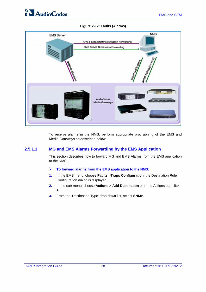
Figure 2-12: Faults (Alarms)
To receive alarms in the NMS, perform appropriate provisioning of the EMS and Media Gateways as described below.
2.5.1.1 MG and EMS Alarms Forwarding by the EMS Application This section describes how to forward MG and EMS Alarms from the EMS application to the NMS.
To forward alarms from the EMS application to the NMS:
1. In the EMS menu, choose Faults >Traps Configuration; the Destination Rule Configuration dialog is displayed.
2. In the sub-menu, choose Actions > Add Destination or in the Actions bar, click +.
3. From the 'Destination Type' drop-down list, select SNMP.

OAMP Integration Guide 2. OAMP Integration Concepts
Version 6.8 29 April 2014
4. In the left-hand pane, provision the following parameters:
• 'Destination Rule Name' as you wish it to appear in the summary screen.
• Select the subset of alarms and events that must be forwarded to the NMS from the following subset (by default, all the alarms and events are selected): ♦ EMS Alarms Forwarding ♦ EMS Events Forwarding ♦ MGW Alarms Forwarding ♦ MGW Events Forwarding
• 'Severities To Forward' – select the subset of severeties that you wish to receive in the NMS application (by default, all the severeties are selected). Note: CLEAR alarms for the selected subset of the alarms are always forwarded.
• Select the Media Gateways from which you wish to forward alarms and events.
5. In the right-hand pane, provision the following parameters:
• In the 'Destination Host IP Address' field, enter the NMS IP address.
• In the 'Destination Host port' field, enter the port number of the destination host (the default SNMP port for trap reception is 162).
Figure 2-13: Traps Forwarding Configuration

EMS and SEM
OAMP Integration Guide 30 Document #: LTRT-19212
Figure 2-14: SNMP Trap Forwarding
Note: EMS issues SNMPv2c traps with the field SNMPv2c Trap Community set to
public.
6. (Optional) Select the 'Enable SNMPv3 Configuration' box to enable forwarding traps to the NMS using SNMPv3. In this case, set the following additional fields:
• In the 'Security Name' field, enter the Security name of the SNMPv3 user.
• From the 'Authentication Protocol' drop-down list, select an authentication protocol. The corresponding security level is displayed in the 'Security Level' field.
• In the 'New Authentication Password' field, enter a new Authentication Password.
• From the 'Privacy Protocol' drop-down list box, select a Privacy Protocol.
• In the 'New Privacy Password' field, enter a new Privacy Password. 7. Click OK.

OAMP Integration Guide 2. OAMP Integration Concepts
Version 6.8 31 April 2014
Note: During the EMS synchronization with the managed gateways, the EMS may recover missed alarms and retrieve them. As part of the alarms definition in the EMS, missed alarms are forwarded to the NMS as well. By default, the synchronization process is performed with the Gateway alarms history tables. In the event of a failure to retrieve a part of the whole alarms history, the EMS notifies the user with one of the following events: 'Synchronizing Alarms Event' and 'Synchronizing Active Alarms Event'. For more details regarding Events fields and suggested corrective actions, see the relevant product OAMP Guide.
2.5.1.2 Each Media Gateway Forwards its Alarms Directly to the NMS This section describes how to forward alarms directly from the nework elements to the NMS.
2.5.1.2.1 EMS Alarms and Events
This section describes how to forward EMS alarms and events to the NMS.
To forward alarms and events from the EMS application:
1. In the EMS menu, choose Faults > Traps Configuration; the Destination Rule Configuration dialog is displayed.
2. In the sub-menu, choose Actions > Add Destination or in the Actions bar, click +.
3. From the Select Destination Type drop-down list, choose SNMP. 4. On the left hand pane, provision the following parameters:
• 'Destination Rule Name' as you wish it to appear in the summary screen.
• Select the subset of alarms and events that must be forwarded to the NMS from the following subset (by default, all the alarms and events are selected): ♦ Enable 'EMS Alarm Forwarding' ♦ Enable 'EMS Event Forwarding'
• Ensure that MGW alarms and events checkboxes are cleared: ♦ Clear 'Enable MGW Alarm Forwarding' ♦ Clear 'Enable MGW Event Forwarding'
• 'Severities To Forward' – select the subset of severeties that you wish to receive in the NMS application (by default, all the severeties are selected). Note: CLEAR alarms for selected subset of the alarms are always forwarded.
• Select the Media Gateways from which you wish to forward alarms and events.
5. In the right-hand pane, provision the following parameters:
• In the 'Destination Host IP Address' field, enter the NMS IP address.
• In the 'Destination Host port' field, enter the port number of the destination host (the default SNMP port for trap reception is 162).

EMS and SEM
OAMP Integration Guide 32 Document #: LTRT-19212
Note: EMS issues SNMPv2c traps with the field 'SNMPv2c Trap Community' set to
public.
6. You can optionally select the 'Enable SNMPv3 Configuration' box to enable forwarding traps to the NMS using SNMPv3. In this case, set the following additional fields:
• In the 'Security Name' field, enter the Security name of the SNMPv3 user.
• From the 'Authentication Protocol' drop-down list, select an authentication protocol; the corresponding security level is displayed in the 'Security Level' field.
• In the 'New Authentication Password' field, enter a new Authentication Password.
• From the 'Privacy Protocol' drop-down list, select a Privacy Protocol.
• In the 'New Privacy Password' field, enter a new Privacy Password. 7. Click OK.
Figure 2-15: Destination Rule Configuration

OAMP Integration Guide 2. OAMP Integration Concepts
Version 6.8 33 April 2014
2.5.1.2.2 Forwarding Mediant 5000/Mediant 8000 Alarms/Events to an NMS
This section describes how to forward Mediant 5000/Mediant 8000 Alarms/Events to an NMS. SNMPv2 Traps In case you wish the NMS to receive SNMPv2 notifications, open the MG Provisioning Frame / Network Services tab and define a new NMS or OSS Trap Destination IP address, port and OAMP security Profile (if you wish to receive traps in SNMPv2c over IPSec protocol-if the Gateway is configured for SNMPv2 traps with IPSec secured).
Note: The Mediant 5000 / Mediant 8000 issues SNMPv2c traps with the field
'SNMPv2c Trap Community' set to public.
SNMPv3 Traps For SNMPv3 Gateways, there is the possibility that the NMS / OSS user will select an SNMPv3 profile that is different to the EMS application defined profile. In this case, the user must perform the procedure below to configure as the SNMPv3 user for the Gateway.
To configure as an SNMPv3 user for the Gateway: 1. Open the Media Gateway Provisioning Frame / SNMPv3 Users Tab. 2. Select a User Profile you would like to create a user from by selecting one of the
rows in the SNMPV3 Users table. Since new users can only be created from existing users, upon Gateway definition as an SNMPv3 Gateway, the initial templates are created.
3. Click the + button; a window prompting you to provide old and new passwords opens. The Default password for all the template users are "123456".
4. Select Manager permission group: 'Trap Only, Read & Trap or Read and Write and Trap'.
5. Select the ‘Enable User as Trap destination' checkbox and define the NMS / OSS IP and Port for receiving traps. EMS defines this manager to the Trap Destinations tab as an SNMPv3 Trap destination.

EMS and SEM
OAMP Integration Guide 34 Document #: LTRT-19212
2.5.1.2.3 Forwarding CPE and MPs Alarms / Events to an NMS
This section describes how to forward CPE and MPs Alarms / Events to an NMS. SNMPv2 Traps In case the NMS wishes to receive SNMPv2 notifications, open the Network Settings Provisioning Frame / SNMP Managers Table tab and define a new NMS or OSS Trap Destination IP address and port. If the gateway is configured as IPSec secured, SNMPv2 traps are sent over the IPSec protocol.
Note: The CPE device issues SNMPv2c traps with the field 'SNMPv2c Trap
Community' set to trapuser.
SNMPv3 Traps For SNMPv3 Gateways, there is a possibility that the NMS / OSS user chooses an SNMPv3 profile that is different to the EMS application SNMPv3 profile. In this case, the user must perform the procedure described below to configure the SNMP gateway as an SNMPv3 user.
To configure as an SNMPv3 user for the gateway: 1. Open the Network Settings Provisioning Frame / SNMPv3 Users tab. 2. Select a User Profile you would like to create a user from by selecting one of the
rows in SNMPV3 Users table. 3. Click the + button; a window prompting you to provide old and new passwords
opens. 4. Select the Manager permission group: Trap Only, Read & Trap or Read & Write
& Trap. 5. Select the 'Enable User as Trap destination' check box and define NMS / OSS IP
and Port for trap reception. The EMS defines this manager in the SNMP Managers Table tab as an SNMPv3 Trap destination.
The figure below is relevant for both the Mediant 5000 / Mediant 8000, for the CPE Gateways and for the MPs.

OAMP Integration Guide 2. OAMP Integration Concepts
Version 6.8 35 April 2014
Figure 2-16: Add New SNMPv3 User Dialog

EMS and SEM
OAMP Integration Guide 36 Document #: LTRT-19212
2.5.2 Alarms Clearing Mechanism All active Alarms and Events for each Media Gateway are cleared upon GATEWAY startup (cold start trap). The active and history alarms tables are emptied. Critical, Major, Minor, Warning or Info alarms are automatically cleared when a Notification (OID) Clear alarm is generated by the same entity (source) and the same Media Gateway that originally generated the Critical, Major, Minor, Warning or Info alarms. Media Gateway events are automatically cleared from the Alarm Browser after a predefined period of time (default – 3 days). When an event becomes obsolete, the operator can also manually delete it.
Note: There is no aging rule for alarms and events clearing.
OAMP Integration Guide 2. OAMP Integration Concepts
Version 6.8 37 April 2014
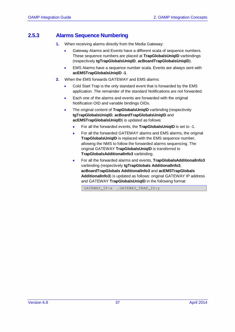
2.5.3 Alarms Sequence Numbering 1. When receiving alarms directly from the Media Gateway:
• Gateway Alarms and Events have a different scala of sequence numbers. These sequence numbers are placed at TrapGlobalsUniqID varbindings (respectively tgTrapGlobalsUniqID, acBoardTrapGlobalsUniqID).
• EMS Alarms have a sequence number scala. Events are always sent with acEMSTrapGlobalsUniqID -1.
2. When the EMS forwards GATEWAY and EMS alarms:
• Cold Start Trap is the only standard event that is forwarded by the EMS application. The remainder of the standard Notifications are not forwarded.
• Each one of the alarms and events are forwarded with the original Notification OID and variable bindings OIDs.
• The original content of TrapGlobalsUniqID varbinding (respectively tgTrapGlobalsUniqID, acBoardTrapGlobalsUniqID and acEMSTrapGlobalsUniqID) is updated as follows: ♦ For all the forwarded events, the TrapGlobalsUniqID is set to -1. ♦ For all the forwarded GATEWAY alarms and EMS alarms, the original
TrapGlobalsUniqID is replaced with the EMS sequence number, allowing the NMS to follow the forwarded alarms sequencing. The original GATEWAY TrapGlobalsUniqID is transferred to TrapGlobalsAdditionalInfo3 varbinding.
♦ For all the forwarded alarms and events, TrapGlobalsAdditionalInfo3 varbinding (respectively tgTrapGlobals AdditionalInfo3, acBoardTrapGlobals AdditionalInfo3 and acEMSTrapGlobals AdditionalInfo3) is updated as follows: original GATEWAY IP address and GATEWAY TrapGlobalsUniqID in the following format:
GATEWAY_IP:x ,GATEWAY_TRAP_ID:y

EMS and SEM
OAMP Integration Guide 38 Document #: LTRT-19212
2.5.4 Alarms Synchronization via MG SNMP I/F Synchronization is supported for alarms and not for events. A carrier-grade alarm system provides a reliable alarm reporting mechanism that takes into account element management system outages, network outages, and transport mechanism, such as SNMP over UDP. This mechanism is implemented in the Media Gateway level SNMP agent, and serves EMS, NMS, or higher level management system synchronization purposes.
Note: The EMS application does not support carrier-grade alarms synchronization
towards the NMS in this version.
A carrier-grade alarm system is characterized by the following:
Active Alarms
The device can determine which alarms are currently active in the device by maintaining an active alarms table. When an alarm is raised, it is added to the active alarms list. Upon alarm clearing, it is removed from the active alarms list. The maximal size of the active alarms table is defined as follows:
• Mediant 5000 / 8000 Gateways – 1.000 alarms
• CPE's – 200 alarms
• MP 11x, MP 124 - 40 alarms When the active alarms list exceeds its maximum size, an enterprise Active Alarms Overflow alarm is sent to the management system.
• The device sends a cold start trap to indicate that it is starting up. This allows the management system to synchronize its view of the device's active alarms.
• Two views of active alarms table are supported by the Media Gateways: ♦ Standard MIB: alarmActiveTable and alarmActiveVariableTable in the
IETF ALARM MIB for all the Media Gateways. ♦ Enterprise MIB: tgActiveAlarmTable in the enterprise TG-ALARM-MIB mib for
Mediant 5000 / 8000 Gateways. acActiveAlarmTable in the AC-ALARM-MIB mib for Mediant
600/800/1000/2000/3000 and MP products. History Alarms
The device allows the recovery of lost alarm raise and clear notifications by maintaining a log history alarms table. Each time an alarm-type trap (raise or clear) is sent, the Carrier-Grade Alarm System adds it to the alarms history list. The trap contains a unique Sequence Number. Each time a trap is sent, this number is incremented. The device allows detection of lost alarms and clear notifications by managing an alarm sequence number and displaying the current number.

OAMP Integration Guide 2. OAMP Integration Concepts
Version 6.8 39 April 2014
The maximal size of the history alarms table is defined as follows:
• Mediant 5000 / Mediant 8000 Gateways – 10.000 alarms
• CPE's – 1.000 alarms
• MP 11x, MP 124 - 100 alarms When the history alarm list exceeds its maximum size, it starts overiding the oldest alarms in the list in cyclic order.
• Two views of log history alarms table are supported by the Media Gateways: ♦ Standard MIB: 'nlmLogTable' and 'nlmLogVariableTable' in the
NOTIFICATION-LOG-MIB for all the Media Gateways. ♦ Enterprise MIB: tgAlarmHistoryTable in the enterprise 'TG-ALARM-MIB' mib for
Mediant 5000 / 8000 Gateways. acAlarmHistoryTable in the 'AC-ALARM-MIB mib' for CPE and MP
products.

EMS and SEM
OAMP Integration Guide 40 Document #: LTRT-19212
2.6 Status / State Management via MG SNMP I/F For details regarding supported SNMP MIBs, refer to the relevant Media Gateway User Guide.
2.7 Provisioning and Maintenance The EMS application is fully responsible for Media Gateway provisioning and maintenance actions, as well as advanced components status display, including, however, not limited to the following:
Overall Media Gateway status screen displaying all components
Managed Objects definition and provisioning
Administrative actions on the MOs (such as lock / unlock, manual switchover / switchback, etc.)
Regional (auxiliary) files downloading
Software upgrade / Online Software Upgrade
The EMS features multiple tools to easily and quickly configure a set of Gateways. For example, after one Gateway is configured and operational, its configuration can be applied to a set of selected Media Gateways of the same type. In the same way, all Gateway maintenance actions tasks, such as reset, software upgrade or downloading regional files, can be performed with a one-click action to a large set of the selected Gateways.
Note: There are no EMS Application APIs available for provisioning and maintenance
actions integration.
For more information on EMS features, refer to the EMS User’s Manual.

OAMP Integration Guide 2. OAMP Integration Concepts
Version 6.8 41 April 2014
2.8 Performance Monitoring Customers often face a complex VoIP network with little or no information on the status and capacities of each component in the network. PMs help the system architect design a better network. In addition, PMs help operators discover malfunctioning devices before they start causing a problem on the production network. The system provides two types of performance measurements:
Gauges: Gauges represent the current state of a PM parameter in the system. Gauges, unlike counters, can decrease in value, and like counters, can increase. For Gauges, the interval data is referred as minimum, maximum and average values.
Counters: Counters always increase in value and are cumulative. Counters, unlike gauges, never decrease in value unless the system is reset. The counters are then zeroed. For Counters, the interval data is referred as last interval value.
Performance Management is composed of real-time and historical data monitoring. Real-time data monitoring can be used to troubleshoot network or system problems and to isolate a problem after it is detected by the fault management system. The EMS application supports graphical representation of the real-time data and provides the user with graphical tools to perform high-frequency polling of various system parameters. For more information in reference to graph types and application User Interface, refer to the EMS User's Manual.
Historical data can be used by NMS and OSS systems for long-term network analysis and planning.
Figure 2-17: Performance Monitoring - Intervals
Time
11:24
System started
11:30 11:45 12:00
1st Interval 2nd Interval Current Interval
12:05 NOW
Real-time view
Performance is usually measured in a constant time interval to which all elements are synchronized. Intervals commence on the hour - expiring at 12:00:00, 12:15:00, 12:30:00, 12:45:00, etc. This allows synchronization of several elements in the system to the same interval time frame. Note that the first interval after start-up is always shorter (in the above example, the first interval only lasts 6 minutes - so that a new interval can start at 11:30:00). AudioCodes equipment support 15-minute intervals for historical performance monitoring data collection.
Note: To perform accurate history PM polling, all the network elements (MG, EMS, NMS.) must be synchronized on the same NTP server. The EMS server machine can be defined as an NTP server machine.

EMS and SEM
OAMP Integration Guide 42 Document #: LTRT-19212
The NMS can receive performance monitoring data by using one of the following methods:
By collecting .csv or .sml files fom the EMS server machine via FTP or SFTP. EMS performs SNMP polling of the network elements and creates a summary file per element per collection interval (purple-colored path in the figure below). See Section 2.8.1 on page 43 and Section 2.8.2 on page 46.
By collecting information directly from the network element via the SNMP interface (green-colored path in the figure below). See Section 2.8.3 on page 46.
Figure 2-18: Performance Monitoring
OAMP Integration Guide 2. OAMP Integration Concepts
Version 6.8 43 April 2014
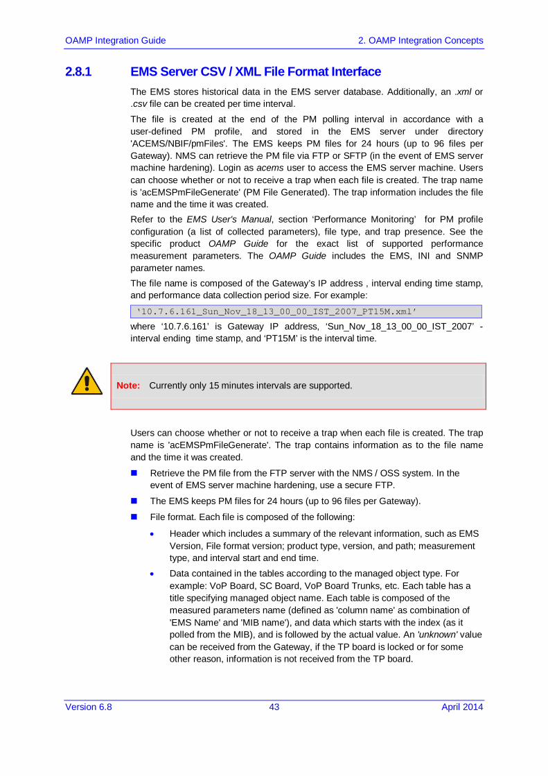
2.8.1 EMS Server CSV / XML File Format Interface The EMS stores historical data in the EMS server database. Additionally, an .xml or .csv file can be created per time interval.
The file is created at the end of the PM polling interval in accordance with a user-defined PM profile, and stored in the EMS server under directory 'ACEMS/NBIF/pmFiles'. The EMS keeps PM files for 24 hours (up to 96 files per Gateway). NMS can retrieve the PM file via FTP or SFTP (in the event of EMS server machine hardening). Login as acems user to access the EMS server machine. Users can choose whether or not to receive a trap when each file is created. The trap name is 'acEMSPmFileGenerate' (PM File Generated). The trap information includes the file name and the time it was created. Refer to the EMS User's Manual, section ‘Performance Monitoring’ for PM profile configuration (a list of collected parameters), file type, and trap presence. See the specific product OAMP Guide for the exact list of supported performance measurement parameters. The OAMP Guide includes the EMS, INI and SNMP parameter names. The file name is composed of the Gateway’s IP address , interval ending time stamp, and performance data collection period size. For example:
‘10.7.6.161_Sun_Nov_18_13_00_00_IST_2007_PT15M.xml’
where ‘10.7.6.161’ is Gateway IP address, ‘Sun_Nov_18_13_00_00_IST_2007’ - interval ending time stamp, and ‘PT15M’ is the interval time.
Note: Currently only 15 minutes intervals are supported.
Users can choose whether or not to receive a trap when each file is created. The trap name is 'acEMSPmFileGenerate'. The trap contains information as to the file name and the time it was created.
Retrieve the PM file from the FTP server with the NMS / OSS system. In the event of EMS server machine hardening, use a secure FTP.
The EMS keeps PM files for 24 hours (up to 96 files per Gateway).
File format. Each file is composed of the following:
• Header which includes a summary of the relevant information, such as EMS Version, File format version; product type, version, and path; measurement type, and interval start and end time.
• Data contained in the tables according to the managed object type. For example: VoP Board, SC Board, VoP Board Trunks, etc. Each table has a title specifying managed object name. Each table is composed of the measured parameters name (defined as 'column name' as combination of 'EMS Name' and 'MIB name'), and data which starts with the index (as it polled from the MIB), and is followed by the actual value. An 'unknown' value can be received from the Gateway, if the TP board is locked or for some other reason, information is not received from the TP board.

EMS and SEM
OAMP Integration Guide 44 Document #: LTRT-19212
2.8.1.1 CSV File Format The file header contains the device information.
Figure 2-19: Background Monitoring csv File
PM File Version 0.2 AudioCodes EMS Version 5.4.27
Earliest Start Time: Example: Thu-Dec-29-10:00:00-IST-2005
Latest Capture: Example - TimeThu-Dec-29-10:15:00-IST-2005
MeasurementKind ="PeriodBased" IntervalDuration="PT15M"
Product: Hardware Type; software version
Product Path:\xxxx\xxx

OAMP Integration Guide 2. OAMP Integration Concepts
Version 6.8 45 April 2014
2.8.1.2 XML File Format The concept is the same as the csv file's format. Below are examples of the file header and content.
Figure 2-20: xml File Header Example
Figure 2-21: xml File Data Example

EMS and SEM
OAMP Integration Guide 46 Document #: LTRT-19212
2.8.2 Mediant 5000 and Mediant 8000 CSV File Format Interface Refer to the Mediant 5000 and Mediant 8000 Alarm and Performance Monitoring Guide for the exact list of supported performance measurement parameters. This Guide includes both EMSand SNMP parameter names. The file is created at the end of the PM polling interval and includes all the PM parameters supported by the GATEWAY. Files are stored and can be retrieved from the GATEWAY Global IP address under directory '/Project/bin/log/pm'. The GATEWAY keeps PM files for 24 hours (up to 96 files per Gateway). NMS can retrieve the PM file via FTP or SFTP (in case of GATEWAY hardening). File name and file structure are identical as for the EMS CSV file.
2.8.3 Media Gateway SNMP Interface Refer to the Mediant 5000 and Mediant 8000 Alarm and Performance Monitoring Guide for the exact list of supported performance measurement parameters for the Mediant 5000 and Mediant 8000. Refer to the specific product CPE OAM Guide for the exact list of supported performance measurement parameters for the CPE products. These Guides include both EMS and SNMP parameter names. The following information refers to Mediant 5000 / Mediant 8000 Gateways:
The only valid SNMP agent for PMs Polling is MG Global IP address on the SC, and PM MIBS provided as part of the Mediant 5000/Mediant 8000 SW package (SC board).
To perform accurate polling of the parameters defined as 'Hist' in the OAM Guides, the following read-only parameters are available at the MG level: • 'PM Operative State' – read-only - (tgMGInfoPMOperativeState) – history
data can be collected only when PM Operative State is enabled.
• 'Sample Time' - read-only - (tgMGInfoSampleTime) – Statistics sample period (seconds). How often the System Controller samples SC related parameters.
• 'Report Period' - read-only - (tgMGInfoReportPeriod) – Statistics report period (seconds), in the current version only 15 minute sample periods are supported (900 seconds).
• Current Interval Collection status – read-only - (tgMGInfoHistoryIntervalStatus) –Indicates whether the MG history collection is in progress or completed. When MG status is reported as completed, the management system can start polling the latest history parameters (see 'RT / Hist mark' in the parameters tables').
• MG Last Interval End Time – read-only - ('tgMGInfoLastIntervalEndingTime) – When the last polling interval became available at the MG level. This information is inserted together with the following: ♦ 'Board Last Interval Time' – read-only -
(tgMGInfoBoardLastIntervalTime) – TP Board report last interval time. For example, when returned value is 2006-2-2 16:15:00, last polling interval include information for 2006-2-2, 16:00:00 – 16:15:00. The information is available in the MG level when the Current Interval Collection Status receives 'complete' value.
OAMP Integration Guide 2. OAMP Integration Concepts
Version 6.8 47 April 2014
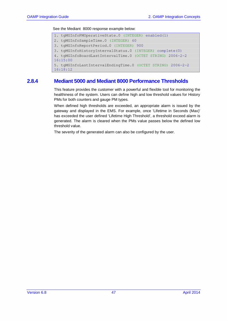
See the Mediant 8000 response example below:
1. tgMGInfoPMOperativeState.0 (INTEGER) enabled(1) 2. tgMGInfoSampleTime.0 (INTEGER) 60 3. tgMGInfoReportPeriod.0 (INTEGER) 900 3. tgMGInfoHistoryIntervalStatus.0 (INTEGER) complete(0) 4. tgMGInfoBoardLastIntervalTime.0 (OCTET STRING) 2006-2-2 16:15:00 5. tgMGInfoLastIntervalEndingTime.0 (OCTET STRING) 2006-2-2 16:18:12
2.8.4 Mediant 5000 and Mediant 8000 Performance Thresholds This feature provides the customer with a powerful and flexible tool for monitoring the healthiness of the system. Users can define high and low threshold values for History PMs for both counters and gauge PM types. When defined high thresholds are exceeded, an appropriate alarm is issued by the gateway and displayed in the EMS. For example, once 'Lifetime in Seconds (Max)' has exceeded the user defined ‘Lifetime High Threshold’, a threshold exceed alarm is generated. The alarm is cleared when the PMs value passes below the defined low threshold value. The severity of the generated alarm can also be configured by the user.

EMS and SEM
OAMP Integration Guide 48 Document #: LTRT-19212
2.9 Security Aspects To understand application and network security between the EMS and the Media Gateway, refer to the 'Security Management' section in the EMS User’s Manual. The following aspects are relevant for the NMS application when integrating the EMS and the Media Gateway:
EMS Users Management (Authentication and Authorization). See below
Network Communication Protocols. See Section 2.9.1.1 on page 49.
2.9.1 EMS Users Management (Authentication and Authorization) EMS users can be managed either locally in the EMS server database, or via a centralized RADIUS, TACACS+ or LDAP server. The figure below shows the different authentication and authorization options:
Figure 2-22: EMS Users-External Authentication and Authorization

OAMP Integration Guide 2. OAMP Integration Concepts
Version 6.8 49 April 2014
2.9.1.1 Authentication and Authorization using a Radius Server Customers may enhance the security and capabilities of logging into the EMS application by using a Remote Authentication Dial-In User Service (RADIUS) to store numerous usernames, passwords and access level attributes. This feature allows multiple user management on a centralized platform. RADIUS (RFC 2865) is a standard authentication protocol that defines a method for contacting a pre-defined server and verifying a given name and password pair against a remote database in a secure manner. When accessing the EMS application, users must provide a valid username and password of up to 128 Unicode characters. EMS doesn’t store the username and password; however, forwards them to the pre-configured RADIUS server for authentication (acceptance or rejection). The local EMS users and passwords defined in the Users’ List can be used as a fallback mechanism in case the RADIUS servers do not respond. EMS supports the provisioning of up to three Radius servers for redundancy purposes. When the first server does not respond, the EMS proceeds to the second server, and then to the third server. EMS will always start working with the previously responded server that is indicated as the Current Active Radius servers.
2.9.1.1.1 Setting Up the Radius Server
This section describes an example of a RADIUS server configuration. You must configure the EMS server as a RADIUS client to perform authentication and authorization of EMS users using the RADIUS server from the EMS application. The example configuration is based on FreeRADIUS, which can be downloaded from the following location: www.freeradius.org. Follow the directions on this site for information on installing and configuring the server.
Note: If you use a RADIUS server from a different vendor, refer to appropriate
documentation.

EMS and SEM
OAMP Integration Guide 50 Document #: LTRT-19212
To set up a RADIUS server using FreeRADIUS:
1. Define the EMS server as an authorized client of the RADIUS server, with a predefined 'shared secret' (a password used to secure communication) and a 'vendor ID'. The figure below displays an example of the file 'clients.conf' (FreeRADIUS client configuration).
Example of the File clients.conf (FreeRADIUS Client Configuration) # # clients.conf - client configuration directives # client 10.31.4.47 { secret = FutureRADIUS shortname = ems }
2. If access levels are required, set up a VSA dictionary for the RADIUS server and select an attribute ID that represents each user's access level. The following example shows a dictionary file for FreeRADIUS that defines the attribute 'ACL-Auth-Level' with ID=35.
Example of a Dictionary File for FreeRADIUS (FreeRADIUS Client Configuration) # # AudioCodes VSA dictionary # VENDOR AudioCodes 5003 ATTRIBUTE ACL-Auth-Level 35 integer AudioCodes VALUE ACL-Auth-Level ACL-Auth-Monitor 50 VALUE ACL-Auth-Level ACL-Auth-Operator 100 VALUE ACL-Auth-Level ACL-Auth-Admin 200
3. In the RADIUS server, define the list of users authorized to use the gateway, using one of the password authentication methods supported by the EMS server implementation. The following example shows a user configuration file for FreeRADIUS using a plain-text password.
Example of a User Configuration File for FreeRADIUS Using a Plain-Text Password # users - local user configuration database john Auth-Type := Local, User-Password == "qwerty" Service-Type = Login-User, ACL-Auth-Level = ACL-Auth-Monitor larry Auth-Type := Local, User-Password == "123456" Service-Type = Login-User, ACL-Auth-Level = ACL-Auth-Admin
4. Record and retain the IP address, port number, 'shared secret', vendor ID and VSA access level identifier (if access levels are used) used by the RADIUS server.
5. Provision the relevant EMS parameters according to the section below.
OAMP Integration Guide 2. OAMP Integration Concepts
Version 6.8 51 April 2014
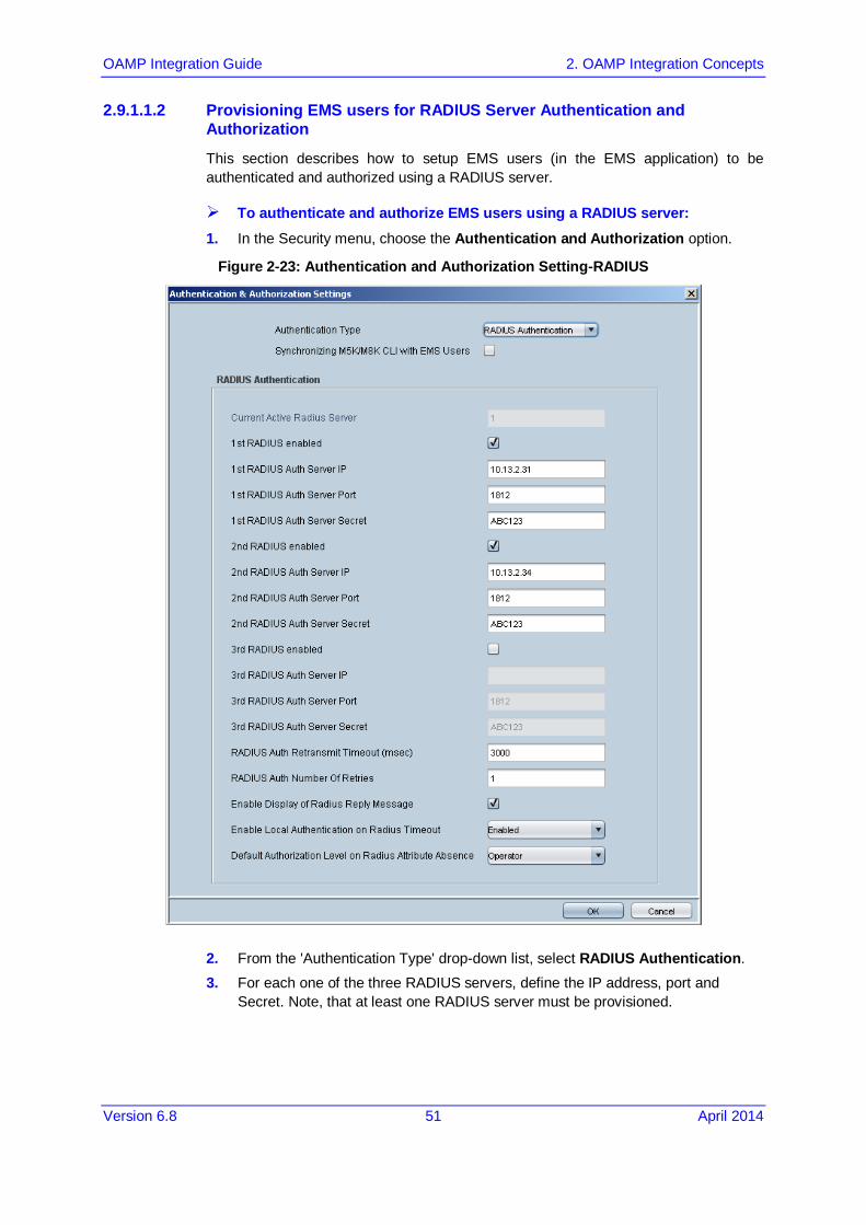
2.9.1.1.2 Provisioning EMS users for RADIUS Server Authentication and Authorization
This section describes how to setup EMS users (in the EMS application) to be authenticated and authorized using a RADIUS server.
To authenticate and authorize EMS users using a RADIUS server: 1. In the Security menu, choose the Authentication and Authorization option.
Figure 2-23: Authentication and Authorization Setting-RADIUS
2. From the 'Authentication Type' drop-down list, select RADIUS Authentication.
3. For each one of the three RADIUS servers, define the IP address, port and Secret. Note, that at least one RADIUS server must be provisioned.

EMS and SEM
OAMP Integration Guide 52 Document #: LTRT-19212
4. Define the following parameters:
• RADIUS Auth Retransmit Timeout' (default-3000 msec)
• RADIUS Auth Number of Retries (default-1) Note that these parameters will be used for each one of the Radius Servers.
5. Determine if you wish to display the Radius Reply message. By default, the parameter 'Enable Display of Radius Reply Message' is enabled.
6. Define EMS behavior in case the RADIUS server does not respond. By default EMS local authentication is enabled. When the 'Enable Local Authentication on Radius Timeout' parameter is enabled, it’s possible to select the 'Synchronize M5K / M8K with EMS Users' option. In this case, EMS updates each one of the managed nodes upon any of the User’s List changes (add, remove, and update users). To provision the list of local users and their properties, refer to Section 'User’s List'. For more information, refer to Section 'Local Users Management in the EMS Application' in the EMS User’s Manual.
7. Define EMS behavior in case the RADIUS server response does not include Authorization Vendor Specific Element (described above). In this case, the Administrator can either deny user access or set a default security level to grant to the user. By default, EMS provides access to the application and provisions an Operator security level to the user (see parameter 'Default Authorization Level on Radius Attribute Absence').
8. Click OK.
2.9.1.2 Authentication and Authorization using a TACACS+ Server Customers can enhance the security and capabilities of logging into the EMS application by using a Terminal Access Controller Access-Control System Plus (TACACS+) to store numerous usernames, passwords and access level attributes. This feature allows multiple user management on a centralized platform. TACACS+ is defined in RFC 1492 and considered as more secure than the RADIUS server. TACACS+ provides separate authentication, authorization and services, runs over TCP, encrypts the entire body of the packet, and offers multiprotocol support. When accessing the EMS application, users must provide a valid username and password of up to 128 Unicode characters. The EMS then forwards these usernames and passwords to the pre-configured TACACS+ server for authentication (acceptance or rejection) and also stores the username and password after each successful login in the EMS application for caching purpose. The local EMS users and passwords cache, defined in the Users’ List, can be used as a fallback mechanism in case a connection cannot be established with the TACACS+ servers. The EMS supports provisioning of up to three TACACS+ servers for redundancy purposes. When the first EMS server does not respond, EMS proceeds to the second server, and then to the third EMS server. EMS will always start working with the previously responded server that is defined as 'Current Active TACACS+ server'.

OAMP Integration Guide 2. OAMP Integration Concepts
Version 6.8 53 April 2014
2.9.1.2.1 Setting Up the TACACS+ Server
This section describes an example of a TACACS+ server configuration. The EMS application must be configured to work as a TACACS+ client to perform authentication and authorization of EMS users with a TACACS+ server. The example configuration is based on a Developer's kit source code for Cisco's Unix TACACS+ daemon (this package was created using the original Cisco source code and was compiled to run under Windows). This configuration can be downloaded from the following location: http://www.xpresslearn.com. Follow the directions on this site for information on installing and configuring the server.
Note: If you use a TACACS+ server from a different vendor, refer to its appropriate
documentation.
To set up a TACACS+ server using the above software:
1. In the TACACS+ server, define the list of users authorized to use the Gateway, using one of the password authentication methods supported by the server implementation. The following example shows a user configuration file for a TACACS+ server using a plain-text password. The following access levels must be used to configure the user privilege level:
• Monitoring Authorization > priv-lvl = 0
• Operator Authorization > priv-lvl = 1
• Administrator Authorization > priv-lvl = 15 Example of a User Configuration File (tac.cfg) for TACACS+ Using a Plain-Text Password # CONFIGURE ENCYPTION KEY key = pass_1234 # Configure User user = username { pap = cleartext "password" chap = cleartext "password" service = exec { priv-lvl = 15 }
2. Record and retain the IP address, 'shared secret', and access level identifier (if access levels are used) used by the TACACS+ server.
3. Provision the relevant EMS parameters according to the section below.

EMS and SEM
OAMP Integration Guide 54 Document #: LTRT-19212
2.9.1.2.2 Provisioning TACACS+ client (AXL software) Stand-alone Application
Define the following sequence of files to setup an authorized client of the TACACS server, with a predefined ‘shared secret’ (a password used to secure communication) and a vendor ID. The figure below displays an example of the file example.properties (AXL TACACS+ Client configuration). Example of the File example Properties (AXL TACACS+ Client Configuration) # Example properties file. # This contains some properties required by the examples. # Edit this file to match your set up. # TACACS+ Server domain name or address. ServerAddress = 10.7.2.200 # The secret shared between the server and client. ServerSecret = pass_1234 # The login name. Name = username # The login password. Password = password # The port name for the client. # This is NOT the server's port number but an # arbitrary name for the client. Something like 'tty6' or # 'Port 99' PortName = tty6 # The client's Remote Address value. This is not necessarily # the client's IP address, but another arbitrary string # describing the client's location. It could be 'Router 12' # or 'Wiring Closet near the front door' RemoteAddress = RouterOne
OAMP Integration Guide 2. OAMP Integration Concepts
Version 6.8 55 April 2014
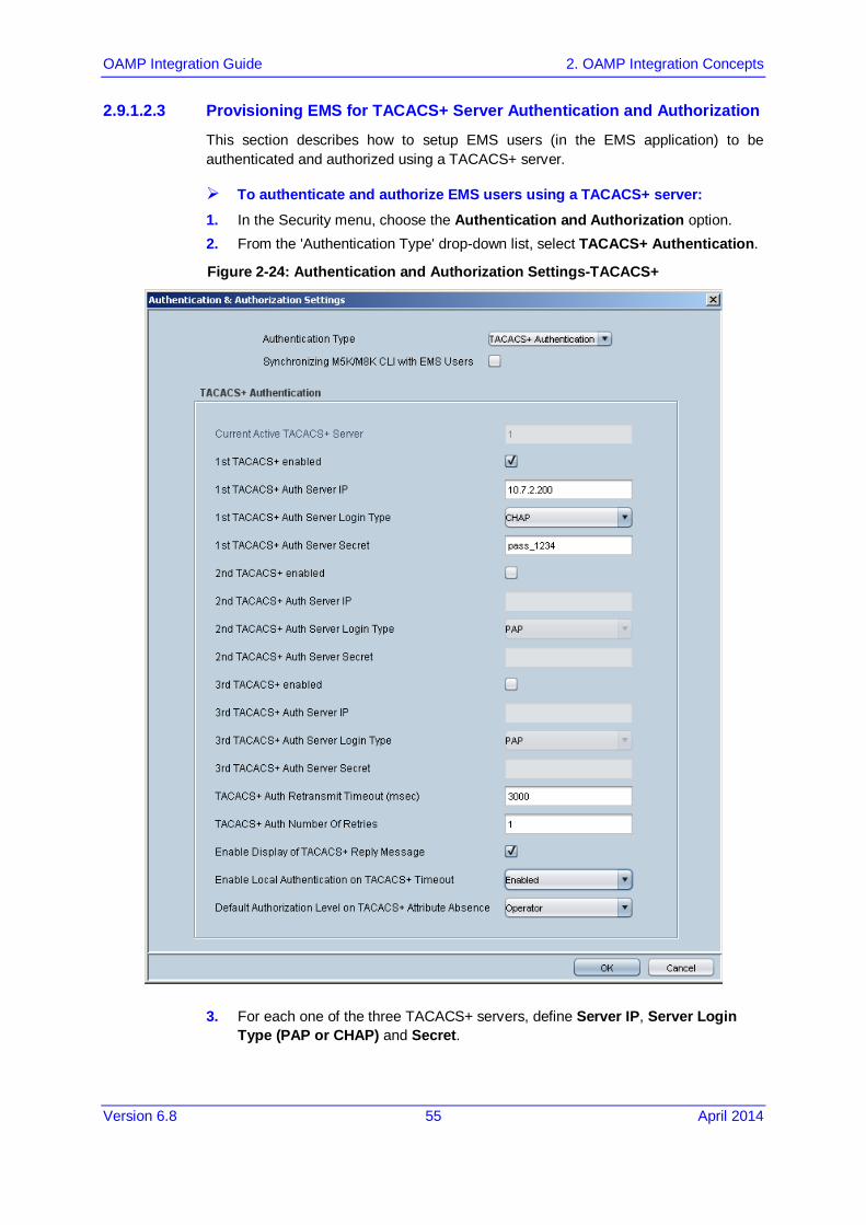
2.9.1.2.3 Provisioning EMS for TACACS+ Server Authentication and Authorization
This section describes how to setup EMS users (in the EMS application) to be authenticated and authorized using a TACACS+ server.
To authenticate and authorize EMS users using a TACACS+ server: 1. In the Security menu, choose the Authentication and Authorization option. 2. From the 'Authentication Type' drop-down list, select TACACS+ Authentication.
Figure 2-24: Authentication and Authorization Settings-TACACS+
3. For each one of the three TACACS+ servers, define Server IP, Server Login Type (PAP or CHAP) and Secret.

EMS and SEM
OAMP Integration Guide 56 Document #: LTRT-19212
Note:
• The TACACS+ server receives messages on TCP port number 49 (defined by TACACS+ protocol).
• At least one TACACS+ server must be provisioned
4. Define the following parameters:
• TACACS+ Server Retransmit Timeout (Default-3000 msec)
• Number of Retries (Default-1) Note that these parameters will be used for each one of the TACACS+ servers.
5. Define if you wish to display the TACACS+ Reply message. By default the parameter 'Enable Display of TACACS+ Reply Message' is enabled.
6. Define the EMS behavior in case a connection cannot be established with any of the TACACS+ servers. By default, EMS local authentication is enabled by the parameter 'Enable Local Authentication on TACACS+ Timeout' and all the successfully logged in users are saved in the EMS server 'User’s List' cache. In this case, it’s also possible to select the 'Synchronize M5K/M8K CLI with EMS Users' option. When this option is selected, EMS updates each one of the managed Media Gateway nodes whenever user management actions are performed in the EMS (add, remove, and update users in the User’s List). For more information, refer to 'Local Users Management' in the EMS Application in the EMS User’s Manual.
7. Define the EMS behavior in case the TACACS+ server response does not include the Authorization Vendor Specific Element (described above). In this case, the Administrator can either deny user access or grant a default security level to the user. By default, the EMS provides access to the application and provisions the user with an Operator security level (see parameter 'Default Authorization Level on TACACS+ Atrribute Absence').

OAMP Integration Guide 2. OAMP Integration Concepts
Version 6.8 57 April 2014
2.9.1.3 Authentication and Authorization using an LDAP Server This section describes how to setup EMS users (in the EMS application) to be authenticated and authorized using an LDAP server.
To authenticate and authorize EMS users using an LDAP server.
1. In the EMS menu, choose Security > Authentication & Authorization; the Radius Authentication & Authorization Settings screen is displayed.
2. From the Authentication Type drop-down list, select LDAP Authentication.
Figure 2-25: LDAP Authentication and Authorization
3. Configure the IP address of the LDAP Authentication server. 4. Configure other parameters as required.

EMS and SEM
OAMP Integration Guide 58 Document #: LTRT-19212
2.9.2 Network Communication Protocols The following describes the different EMS network communication protocols:
EMS Client - Server communication is secured using RMI (Remote Method Invocation) protocol over SSL (Secure Sockets Layer). EMS also enables client installation and launching via JAWS running over HTTPS.
EMS Server – managed Gateways communication can be secured as following:
• Mediant 5000 / Mediant 8000: ♦ SNMPv3 for Provisioning, Maintenance Action, Faults and Performance
Monitoring ♦ SSH and SCP for File transfer and Online Software Upgrade ♦ IPsec with an IKE pre-shared key for other communication (like NTP)
• CPE's: ♦ SNMPv3 for Provisioning, Maintenance Action, Faults and Performance
Monitoring ♦ HTTPS for File transfer and Online Sotwware Upgrade ♦ IPsec with an IKE pre-shared key for other communication (like NTP)
EMS server secure access- the secure access to the EMS server machine is possible via SSH and SFTP protocols to perform maintenance actions and access files. SNMPv3 traps can be forwarded from the EMS server machine. In addition, overall EMS server connectivity can be secured using the IPSec protocol (with the IKE pre-shared key).
In each one of the options below, User Authentication and Authorization is performed either via the EMS Application local database, or via centralized Radius or TACACS+ server in accordance with the Security profile configured by the Administrator User of the EMS application. For more information, refer to the 'Security Management' chapter in the EMS User's Manual.

OAMP Integration Guide 3. EMS Private Labeling
Version 6.8 59 April 2014
3 EMS Private Labeling This section describes private labeling for the EMS.
3.1 Overview Private labeling is designed to enable the customer to customize EMS and Media Gateway labeling according to their specific requirements. This allows the customer to use the EMS under their own company name, Gateway names, logos and images. The customization process involves preparing files and images as described in this document, and then packaging these files and images in a custom .zip file. At the end of the customization process, customer must create a new DVD that includes the custom.zip file. This zip file is then placed on the customer prepared DVD. The following items are customized by the private labeling process:
License agreement document replacement
Company Logos & Icons
Company name, MG and TP boards naming
Online Help
Note: The customer must verify that the EMS server installation is working properly after the server branding procedure. Client / Server communication and Media Gateway configuration are also required as minimal sanity testing of the branding DVDs.
3.2 Private Labeling Procedure This section describes the Private Labeling procedure. The Audiocodes EMS DVD includes a folder named 'PrivateLabeling'. This folder contains all of the files required for performing Private Labeling. Once the files in this folder are updated, they must be compressed and placed on a new DVD.
3.2.1 Creating a New Customer Specific EMS DVD The new EMS DVD must include the following folders:
Documentation/Patches: Note that default documentation set provided in the EMS DVD is AudioCodes branded and customers must replace all the documentation according to their branding requirements. The Patches folder must remain unchanged: Documentation/PrivateLabeling; this folder is an intermediate folder that must not be located on the customized DVDs.
EmsClientInstall: to create new, private labeled DVDs, the customer must perform all the required updates in a default custom.zip file, and then replace the existing 'EmsClientInstall' file in the PrivateLabeling/EmsClientInstall folder. For more information, see Section 3.2 on page 59 and Section 3.2.3 on page 64.

EMS and SEM
OAMP Integration Guide 60 Document #: LTRT-19212
EmsServerInstall: The new EMS server software file created as a result of the procedure described in Section 3.2.3 on page 64 below must replace the existing EMSServerInstall file in the EmsServerInstall folder.
3.2.2 Custom ZIP file To open the encrypted .zip file, the password "pass_1234" must be used. The file must be closed with the same password.
3.2.2.1 Overview The following diagram illustrates the components of the Custom .zip file.
Figure 3-1: Custom ZIP File

OAMP Integration Guide 3. EMS Private Labeling
Version 6.8 61 April 2014
3.2.2.2 Images Folder The Images folder includes all the default replacements for all the icons and images (in the original application is the AudioCodes logo). Customers can replace these images, while the file name and image size are not changed.
Note: It is recommended to use the same color convention as in the original EMS
application.
The Table below summarizes the details of each image:
Image Name Image Size Format Description
login_image6_0.gif 439X359 JPG Background picture in the Login Screen
bottom_left_image.gif 155X104 PNG Image located in the bottom of the EMS Tree Panel
For more information, see Section A on page 69.
3.2.2.3 localeProperties Folder Currently not in use.

EMS and SEM
OAMP Integration Guide 62 Document #: LTRT-19212
3.2.2.4 ProductNames Folder The ‘ProductNames’ folder includes ASCII file named product_names properties file. This file includes Company Name and names of all the Audiocodes products supported by EMS. For some of the products, VoP board names can also be customized. Most of the products have full and short names. When the full name is changed or removed, the short name must be updated accordingly. This file includes:
Company Name – to change the company name, the ‘AudioCodes’ string must be replaced with the new company name.
Product Full Names - Customer must change product names to the right-hand side of the equals mark. The left hand-side name is used internally by the EMS application and must not be changed. For example, when you want to change 'Mediant 5000’ product name to MyGATEWAY 5K', the default line #1 must be replaced with line #2. When the user wishes to remove the product name from the EMS application, the default definition (line#1) must be replaced with line#3 below:
Line#1: Mediant_5000=Mediant 5000 Line#2: Mediant_5000=MyGATEWAY 5K Line#3: Mediant_5000=
Following is a list of the currently used full names:
• Mediant_5000
• Mediant_8000
• Mediant_2000
• Mediant_3000
• Mediant_1000
• Mediant_800MSBG
• Mediant_1000MSBG
• Mediant_600
• MediaPack
Product Short Names:
• Company=
• MediaPack=
• Mediant_600=
• Mediant_800_Msbg=
• Mediant_800_Pro=
• Mediant_1000_Msbg=
• Mediant_1000_Pro=
• Mediant_1000=
• Mediant_2000=

OAMP Integration Guide 3. EMS Private Labeling
Version 6.8 63 April 2014
• Mediant_3000=
• Mediant_5000=
• Mediant_8000=
• MP=
• M1K=
• M2K=
• M3K=
• M5K=
• M8K=
VoP Board Names:
• Tp_1610
• Tp_6310
• Ipm_6310
• Tp_8410
• Ipm_8410
3.2.2.5 Online Help Folder By default, the Online Help folder is empty. This implies that when customers don’t perform Online Help branding, the Online Help feature is disabled by the EMS application and when 'Online Help' is clicked, the information message: 'Online Help is not supported' is displayed. The reason for this is that Online Help is created based on the EMS documentation, which includes multiple references to AudioCodes’ original product names, company logos, etc. To perform branding of the Online Help, the customer must copy all the files from the 'PrivateLabeling/OnlineHelp' folder, and update all the .html files (about 1050 HTML files).
Note:
•
Note:
• Only the content of these files can be updated. The names (an index number) MUST remain unchanged.
• The content of the file 'index.xml' can be updated for the help index view. The links numbers MUST remain unchanged.
• The content of the file 'toc.xml' can be updated for the help content view. The links numbers MUST remain unchanged.

EMS and SEM
OAMP Integration Guide 64 Document #: LTRT-19212
3.2.3 EMS Server Full Branding Process This section describes the procedure to customize EMS server software. During the customization procedure, the EMS server software tar file is opened, modified, signed, and closed again. The modified file must be placed on the new customer CD/DVD.
Note: To perform server branding, the EMS server must meet the minimum requirements as specified in the 'EMS System Requirements' in the EMS Users Manual.
To customize EMS Server Software:
1. Copy the entire folder 'PrivateLabeling/EmsServerInstall' content to the EMS server machine 'ACEMS' folder. The folder content includes the following:
• 'emsServerDeploy_6.x.y.tar' – EMS server original software file custom.zip file prepared as part of EMS client branding (see Section 3.2 on page 59 and Section 3.2.2 on page 60).
• 'unzip' – unzip software required by EMS application.
• 'branding.sh' – the script that the customer must run to create a new ems 'ServerDeploy_5.x.y.tar file'.
2. Change permission of 'branding.sh' to executable, by running the following command:
[root] chmod 755 branding.sh
To perform jars signing, the customer can use it’s own jar signing file 'jarsKeyStore', which is placed in the 'ACEMS' folder. If there is no customer specific file, EMS uses its own default file. Run 'server_branding_script'. This script requires the original EMS server software file 'emsServerDeploy_6.x.y.tar' as input parameter.
[root] ./branding.sh 6.x.y
This script performs server software opening, modifications, and jars signing:
When user specific 'jarsKeyStore' file is found, the user is prompted to provide Keystore alias and storepass for keystore for each one of the jars (see Example 1 below).
If the specific 'jarsKeyStore' file was also created with key password, then the user is prompted to also provide keyPass for each one of the jars.
When the user specific 'jarsKeyStore' file is not found, the user does not need to provide any key and password (see Example 2 below).
Note: In the event of errors, the script details the errors, and the initial
'emsServerDeploy_6.x.y.tar file' is restored.

OAMP Integration Guide 3. EMS Private Labeling
Version 6.8 65 April 2014
When the server_branding_script completes running, a new 'emsServerDeploy_6.x.y.tar' EMS server file is created. This file must replace the default (ACL branded) server file in the customer DVD.
Note: At the end of the server branding procedure, the customer must verify that the EMS server installation is working properly. Client / Server communication and Media Gateway configuration are also required as minimal sanity testing of the branding DVDs.
Example 1: **************************************** ***** START CUSTOMIZATION PROCESS ***** **************************************** SYSTEM CHECKS =================== Server tar: OK custom.zip: OK unzip: OK Jar keystyore: OK Extracting tar files... ============================ x EmsServerInstall, 0 bytes, 0 tape blocks x EmsServerInstall/ac_ems_deploy, 0 bytes, 0 tape blocks x EmsServerInstall/values.install, 2542 bytes, 5 tape blocks x EmsServerInstall/versionUpgradeMap.txt, 1268 bytes, 3 tape blocks Extracting custom.zip files... =================================== custom.zip extraction: OK Start updating files. This may take 5-10 minutes.[Thu Apr 12 06:48:16 EDT 2007] Replacing images ..... Replacing files ..... Checking help files... ========================= Help files:Not Exist--> Disabling online help Update license agreement =========================== Agreement updated: OK Creating jar for re-signing ==============================

EMS and SEM
OAMP Integration Guide 66 Document #: LTRT-19212
---> configurationProperties ---> emsSwVersionFiles ---> help ---> images ---> localeProperties ---> mibs ---> sounds ---> security Jars re-signing ===================== Signing jars with given key Please provide parameters for jar signing. Enter Keystore alias: Enter storepass for keystore: Error: Keystore alias or password incorrect!! Enter Keystore alias: Enter storepass for keystore: Warning: The signer certificate will expire within six months. ******************************************************* ***** Customization Process Finished Successfully *****

OAMP Integration Guide 3. EMS Private Labeling
Version 6.8 67 April 2014
Example 2: **************************************** ***** START CUSTOMIZATION PROCESS ***** **************************************** SYSTEM CHECKS =================== Server tar: OK custom.zip: OK unzip: OK Jar keystore: Not Exists Extracting tar files... ============================ x EmsServerInstall, 0 bytes, 0 tape blocks x EmsServerInstall/ac_ems_deploy, 0 bytes, 0 tape blocks ... x EmsServerInstall/values.install, 2542 bytes, 5 tape blocks x EmsServerInstall/versionUpgradeMap.txt, 1268 bytes, 3 tape blocks Extracting custom.zip files... =================================== custom.zip extraction: OK ================================================ Start updating files. This may take 5-10 minutes.[Thu Apr 12 03:52:10 EDT 2007] ================================================ Replacing images ..... Replacing files ..... Checking help files... ========================= Help files:Not Exists --> Disabling online help Update license agreement =========================== Agreement updated: OK Creating jar for re-signing ============================== ---> configurationProperties ---> emsSwVersionFiles ---> help ---> images ---> localeProperties ---> mibs ---> sounds ---> security Jars re-signing ===================== Signing jars with self created key

EMS and SEM
OAMP Integration Guide 68 Document #: LTRT-19212
Warning: The signer certificate will expire within six months. ******************************************************* ***** Customization Process Finished Successfully *****

OAMP Integration Guide 3. EMS Private Labeling
Version 6.8 69 April 2014
A Appendix – Private Labeling Icons Icon Description
ACL Login Image
Default Login Image
ACL Tree Image
Default Tree Image

AudioCodes Element Management System (EMS) and Session Experience Manager (SEM)
OAMP (EMS and SEM) Integration Guide
Version 6.8
www.audiocodes.com