OAKTON CON 100/200 manual · OPERATING INSTRUCTIONS OAKTON ® 35607-10, -20 Portable...
28
OPERATING INSTRUCTIONS OAKTON ® 35607-10, -20 Portable Conductivity/°C Meters Printed in Singapore 6/00 R7 68X075502 00806-11 TDS/Conductivity Meter with RS-232 HOLD ON OFF CAL MEAS C MEAS μS ATC CON 200 Series MODE SET MI MR ENTER RANGE 20. Warranty OAKTON warrants this meter to be free from significant deviations in material and workmanship for a period of one year from date of purchase. OAKTON warrants this probe to be free from significant deviations in material and workmanship for a period of six months from date of purchase. If repair or adjustment is necessary and has not been the result of abuse or misuse within the warrantied time period, please return—freight prepaid—and correction will be made without charge. OAKTON alone will determine if the product problem is due to deviations or customer misuse. Out-of-warranty products will be repaired on a charge basis. 21. Return of items Authorization must be obtained from our Customer Service Department before returning items for any reason. When applying for authorization, please include data regarding the reason the items are to be returned. For your protection, items must be carefully packed to prevent damage in shipment and insured against possi- ble damage or loss. We will not be responsible for damage resulting from careless or insufficient packing. A restocking charge will be made on all unauthorized returns. NOTE: We reserve the right to make improvements in design, construction, and appearance of products without notice.
Transcript of OAKTON CON 100/200 manual · OPERATING INSTRUCTIONS OAKTON ® 35607-10, -20 Portable...

OPERATING INSTRUCTIONS
OAKTON® 35607-10, -20
Portable Conductivity/°C Meters
Printed in Singapore 6/00 R768X075502 00806-11
TDS/Conductivity Meter with RS-232
HOLD
ONOFF
CALMEAS
C
MEASµS
ATC
CON 200 Series
MODE
SET
MI MR
ENTERRANGE
20. Warranty
OAKTON warrants this meter to be free from significant deviations in material and workmanship for a period of one year from date of purchase. OAKTONwarrants this probe to be free from significant deviations in material and workmanship for a period of six months from date of purchase. If repair or adjustment is necessary and has not been the result of abuse or misuse within the warrantied time period, please return—freight prepaid—and correction will be made without charge. OAKTON alone will determine if the product problem is due to deviations or customer misuse.
Out-of-warranty products will be repaired on a charge basis.
21. Return of items
Authorization must be obtained from our Customer Service Department beforereturning items for any reason. When applying for authorization, please includedata regarding the reason the items are to be returned. For your protection, itemsmust be carefully packed to prevent damage in shipment and insured against possi-ble damage or loss. We will not be responsible for damage resulting from careless orinsufficient packing. A restocking charge will be made on all unauthorized returns.
NOTE: We reserve the right to make improvements in design, construction, andappearance of products without notice.

3
Table of Contents1. Introduction............................................................................................32. Display and keypad functions .............................................................4-5
2.1 Display ...................................................................................................................................42.2 Keypad ...................................................................................................................................5
3. Preparation..........................................................................................6-93.1 Inserting the batteries ..........................................................................................................63.2 Connecting the conductivity cell and temperature sensor ............................................73.3 Attaching the electrode holder to the meter ....................................................................83.4 Inserting the electrode into the electrode holder ............................................................83.5 Attaching two electrode holders ........................................................................................93.6 Connecting the optional AC adapter ................................................................................9
4. Calibration .......................................................................................10-174.1 Important information on meter calibration .................................................................104.2 Preparing the meter for calibration .................................................................................114.3 Conductivity calibration..............................................................................................12-134.4 TDS calibration..............................................................................................................14-154.5 Temperature calibration ....................................................................................................164.6 Errors in calibration ...........................................................................................................17
5. Measurement ...................................................................................18-215.1 Automatic Temperature Compensation .........................................................................185.2 Manual Temperature Compensation ..............................................................................195.3 Taking Measurements .......................................................................................................205.4 Using the manual ranging function ................................................................................21
6. Hold function........................................................................................227. Memory and data input ..................................................................22-23
7.1 Memory Input.....................................................................................................................227.2 Memory Recall ....................................................................................................................23
8. SETUP functions ...............................................................................24-318.1 SETUP Functions at a Glance ...........................................................................................248.2 General Instructions for all SETUP Programs ...............................................................258.3 Program 1: Stored Values.............................................................................................26-278.4 Program 2: Meter Function..........................................................................................28-298.5 Program 3: TDS Function..................................................................................................308.6 Program 4: Communication Set-up.................................................................................31
9. Optional Printer and RS-232 Output Setup ....................................32-439.1 Using with an OAKTON Printer .....................................................................................329.2 Using with a non-OAKTON Printer ..........................................................................32-349.3 Using with a Printer to Download Stored Memory .....................................................359.4 Using with a Computer and the OAKTON Datalog Assist Software ..................36-409.5 Sending Data to the Computer ........................................................................................419.6 Using with a Computer and the OAKTON Datalog Assist Software
to Download Stored Memory ..........................................................................................429.7 View a Data File..................................................................................................................439.8 Printing Errors ....................................................................................................................43
10. Probe care and maintenance..............................................................4411. Probe Replacement........................................................................45-46
11.1 Zero Adjustment ...............................................................................................................4511.2 Two Point Temperature Calibration ..............................................................................46
TDS/Conductivity Meter with RS-232
HOLD
ONOFF
CALMEAS
C
MEASµS
ATC
CON 200 Series
MODE
SET
MI MR
ENTERRANGE
12. Troubleshooting..................................................................................4713. Error Messages....................................................................................4814. Specifications ......................................................................................4915. Accessories .....................................................................................50-5116. Addendum 1: Conductivity to TDS Conversion Factors .....................5217. Addendum 2: Calculating TDS Conversion Factors ............................5318. Addendum 3: Calculating Temperature Coefficients.........................5419. Addendum 4: Calibration Tips............................................................5520. Warranty.............................................................................................5621. Return of Items...................................................................................56
1. Introduction
Thank you for selecting an OAKTON meter. The OAKTON Conductivity/°C; orTDS/Conductivity/°C with RS-232 are portable microprocessor-based instrumentsthat measure conductivity or TDS (models WD-35607-20) and temperature. This meterhas many user-friendly features—all of which are completely accessible through thewater-resistant membrane keypad.
Your meter includes two electrode holders; epoxy platinum probe WD-35607-50 with built-in temperature sensor and cable; batteries and OAKTON PC Datalog AssistSoftware on a 31⁄2” disk (model WD-35607-20 only).
Please read this manual thoroughly before operating your meter.

54
KeypadThe large membrane keypad makes the instrument easy to use. Each button, whenpressed, has a corresponding graphic indicator on the LCD.
ON/OFF ..................Powers and shuts off the meter.
HOLD......................Freezes the measured reading. To activate, press HOLD while inmeasurement mode. To release, press HOLD again
MODE ....................Selects the measurement (or calibration) parameter conductivity,TDS (model 35607-20) or temperature. Press MODE to togglebetween conductivity, TDS and temperature mode.
CAL/MEAS ............Toggles user between Calibration and Measurement mode. • If you were in conductivity measurement mode, press
CAL/MEAS to enter conductivity calibration mode. • If you were in TDS measurement mode, press CAL/MEAS
to enter TDS calibration mode.NOTE: Manual Temperature compensation is accessible from temperature mode; see page 19 for instructions.
ENTER/RANGE ....In Measurement mode—selects range or sets units to auto ranging.In Calibration mode—confirms calibration values.
▲ ▼................▲ /▼ scrolls values up and down in Calibration and SETUP
mode.
MI/MR work in the measurement mode. MI (memory input)stores the measured value into memory. MR (memory recall)recalls the sets of values stored in the memory.
(PRINT) ............Sends measurement to either the printer or computer. On modelswith RS-232/printer option only.
SET ..........................Enters the SETUP mode. Lets you customize the preferences anddefaults.
MI MR
2. Display and Keypad Functions
DisplayThe LCD has a primary and secondary display.
• The primary display shows the measured Conductivity or TDS. • The secondary display shows the temperature of the reading in °C.
The display also shows error messages, keypad functions and program functions.
C
ppmt
ATC
READYMEAS
COND
CALAUTO
µmS
Temp
HOLD
ERR
TDS
mg/L
SETUP
MEMON
OFF
%
2.1
Primary displayMEASurementmode indicator
Secondary display
AUTO rangingindicator
SETup modeindicator
READYindicator
ERRorindicator
Memoryreferenceindicator Low battery
indicatorConductivitycalibrationmode indicator
TDS calibrationmode indicator
AutomaticTemperatureCompensationindicator
2.2
Temperaturecalibrationmode indicator
HOLDindicator
PRINTindicator
HOLD
ONOFF
CALMEAS
MODE
SET
MI MR
ENTERRANGE
CALibrationindicator
MEMory indicator
76
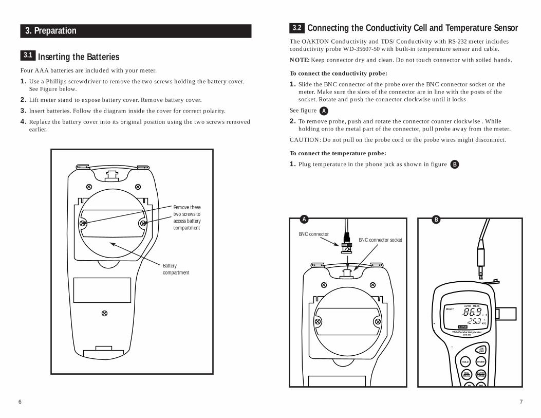
Connecting the Conductivity Cell and Temperature SensorThe OAKTON Conductivity and TDS/Conductivity with RS-232 meter includesconductivity probe WD-35607-50 with built-in temperature sensor and cable.
NOTE: Keep connector dry and clean. Do not touch connector with soiled hands.
To connect the conductivity probe:
1. Slide the BNC connector of the probe over the BNC connector socket on themeter. Make sure the slots of the connector are in line with the posts of the socket. Rotate and push the connector clockwise until it locks
See figure
2. To remove probe, push and rotate the connector counter clockwise . While holding onto the metal part of the connector, pull probe away from the meter.
CAUTION: Do not pull on the probe cord or the probe wires might disconnect.
To connect the temperature probe:
1. Plug temperature in the phone jack as shown in figure
3. Preparation
Inserting the BatteriesFour AAA batteries are included with your meter.
1. Use a Phillips screwdriver to remove the two screws holding the battery cover.See Figure below.
2. Lift meter stand to expose battery cover. Remove battery cover.
3. Insert batteries. Follow the diagram inside the cover for correct polarity.
4. Replace the battery cover into its original position using the two screws removedearlier.
3.1
Battery compartment
Remove thesetwo screws toaccess batterycompartment
3.2
BNC connector socket
TDS/Conductivity Meter
HOLD MODE
ONOFF
CALMEAS
CON 200
MI MR
C
ATC
READYMEAS
COND
AUTO
µ S
ENTERRANGE
BNC connector
A
B
A
B

98
3.3 Attaching the Electrode Holder to the Meter1. Place the electrode holder with the flange facing the slot on the meter.
See Figure
2. Gently slide the flange of the holder into the slot on the meter. Make sure theholder is secured properly into the slot.
You can attach the electrode holder in different positions. See figure
This flexibility facilitates one-hand operation.
Inserting the Electrode into the Electrode HolderTwo electrode holders are included with your meter.
NOTE: Do not use excessive force when inserting electrode into the holder.
1. Insert the conductivity/temperature electrode into the opening of the holderuntil the top housing of the electrode touches the top of the holder.
NOTE: The holder is designed for probes 12 mm in diameter. Electrodes larger than12 mm may not fit in the holder. Forcing the electrode into the opening may damagethe holder or your electrode.
Attaching Two Electrode Holders1. Align the flange of the second electrode
holder with the slot of the first holder. See Figure
2. Slide the flange of the second holder intothe slot of the first holder until the tops ofthe holders are aligned and secure.
Connecting the AC Adapter The AC adapter is not included with your meter; order separately on page 50.
1. Insert the AC jack as shown in figure below.
2. Switch off the meter before plugging the adapter into the power source. This safety precaution protects the software in your meter.
3. Press the ON/OFF button to switch meter on.
Conductivity Meter
B
A
BA
3.4
C
C
D
D
3.5
3.6

1110
For information on how to calibrate your meter:• See section 4.3 on pages 12-13 for Conductivity Calibration• See section 4.4 on pages 14-15 for TDS Calibration• See section 4.5 on page 16 for Temperature Calibration• See section 4.6 on page 17 for Errors in Calibration
Preparing the Meter for CalibrationBefore starting calibration, make sure you are in the correct measurement mode.When you switch on the meter, the meter starts up in the units you shut it off in(either conductivity or TDS depending on model). For example, if you shut themeter off in “ppm” units, the meter will read “ppm” units when you switch themeter on.
For best results, select a conductivity or TDS standard value close to the samplevalue you are measuring. Alternatively use a calibration solution value that isapproximately 2⁄3 the full scale value of the measurement range you plan to use. Forexample in the 0 to 1999 µS range, use a 1413 µS solution for calibration.
Do not reuse calibration solutions after calibration. Contaminants in the solution canaffect the calibration, and eventually the accuracy of the measurements. Use freshcalibration solution each time you calibrate your meter.
NOTE: These meters are factory set to a temperature coefficient of 2% per °C. Formost applications this will provide good results. See Program 1, P1.1 on page26 to set the temperature coefficient to a different value. See Addendum 3,“Calculating Temperature Coefficients” on page 54 to determine the appropriate temperature coefficient for your solution.
4.2
4.1
4. Calibration
Important Information on Meter CalibrationWhen you recalibrate your meter, old conductivity and TDS calibrations are replaced on a range basis. For example, if you previously calibrated your meter at 1413 µS in the 0 to1999 µS range and you recalibrate at 1500 µS also in the 0 to 1999 µS range, the meter will replace the old calibration data (1413 µS) in that range. The meter will retain all othercalibration data in other ranges. To view current calibration points see Program 1, P1.2 inthe SETUP section on page 27.
For meters that also measure TDS (WD-35607-20), calibrating the meter in a conductivity range also calibrates the corresponding TDS range. A calibration value in theTDS mode of a particular range replaces a prior calibration value in the corresponding conductivity mode if both fall in the same range and vice versa. The following table lists thecorresponding conductivity and TDS ranges:
You can calibrate to separate points in each of the five measuring ranges. If you are measuring values in more than one range you should calibrate at multiple standard values tocover those ranges.
To completely recalibrate your meter, or when you use a replacement probe, it is best to clearall calibration data in memory. To erase all old conductivity and TDS calibration data completely from memory, see the SETUP section Program 2, P 2.2 on page 28.
Conductivity Range Function Keys
0.00-19.99 µS 0.00-9.99 ppm
0.0-199.9 µS 10.0-99.9 ppm
0-1999 µS 100-999 ppm
0.00-19.99 mS 1.00-9.99 ppt
0.0-199.9 mS 10.0-99.9 ppt100-200 ppt

1312
6. Press ENTER to confirm the calibrationvalue. The meter returns to the MEAS(measurement) mode.
7. Repeat steps 1-6 for other measuringranges.
Notes
To exit from Conductivity Calibration mode without confirming calibration, DO NOTpress ENTER in step 6. Press CAL/MEAS instead. This will retain the meter’s old calibra-tion data in the measuring range of the calibration.Calibrating for conductivity:
1. If necessary, press the MODE key toselect conductivity mode. The CONDindicator appears in the lower left handcorner of the display.
See figure
2. Rinse the probe thoroughly with de-ionized water or a rinse solution,then rinse with a small amount of calibration solution.
3. Dip the probe into the calibration solution. Immerse the probe tip at least1⁄2 inch into the solution. Stir the probegently to create a homogeneous sample.
4. Press CAL/MEAS to enter conductivitycalibration mode. The CAL indicatorwill flash in the upper right corner ofthe display.
See figure
5. Press the MI/▲ or MR/▼ to change thevalue on the primary display to matchthe value of the calibration standard. NOTE: If the value input into the meterdiffers from the initial value displayedby more than 20% the “ERR” indicatorwill flash. “ERR” signals improperprobe use, a bad calibration solution, orbad calibration technique.
Conductivity calibrationThis instrument is capable of up to 5-point conductivity calibration at one point perconductivity range (0.00-19.99 µS; 0.0-199.9 µS; 0-1999 µS; 0.00-19.99 mS; 0.0-199.9 mS)
B
C
ATC
COND
CALAUTO
ms
4.3
B
C
ATC
READYMEAS
COND
AUTO
µ S
A
A

1514
TDS Calibration (WD-35607-20)
TDS conversion factors:
TDS values are related to conductivity. You can calibrate the meter using conductivity standards as described on page 12 and then program the meter with agiven conversion factor. Enter the conversion factor using the Conductivity to TDSConversion Factor program see page 30, Program 3, P3.0.
Select the conductivity to TDS conversion factor for your solution. Addendum 1 onpage 52 lists some commonly used conversion factors. You can calculate the TDSconversion factor for other solutions as shown in Addendum 2, page 53.
Alternatively, you can calibrate directly to TDS standards using the method below:
Calibrating for TDS:
1. While in the measurement function,press MODE to enter the TDS mode. TheTDS indicator appears in the bottomcenter of the display.
See figure
2. Rinse the probe thoroughly with de-ionized water or a rinse solution,then rinse with a small amount of calibration solution.
3. Dip the probe into the calibration solution. Immerse the probe tip at least1⁄2 inch into the solution. Stir the probegently to create a homogeneous sample.
4. Press CAL/MEAS to enter TDS calibra-tion mode. The CAL indicator will flashin the upper right corner of the display.
See figure
5. Press the MI/▲ or MR/▼ to change thevalue on the primary display to matchthe value of the calibration standard. NOTE: If the value input into the meterdiffers from the initial value displayedby more than 20% the “ERR” indicatorwill flash. “ERR” signals improper probeuse, a bad calibration solution, or badcalibration technique.
4.4
C
pp t
ATC
CALAUTO
TDSB
C
pp t
ATC
READYMEASAUTO
TDSA
B
A
6. Press ENTER to confirm the calibrationvalue. The meter returns to the MEAS(measurement) mode.
7. Repeat steps 1-6 for other measuringranges.
Notes
To exit from TDS Calibration mode without confirming calibration, DO NOT pressENTER in step 6. Press CAL/MEAS instead. This will retain the meter’s old calibrationdata in the measuring range of the calibration.

1716
Temperature CalibrationThe meter allows two types of temperature calibrations called “single point” and“two point” calibrations. Single point calibration is more commonly used. A twopoint calibration is needed only if you are using a replacement probe, see section 11.Probe Replacement page 45-46 for two point temperature calibration. The built-intemperature sensor included in the probe is factory calibrated, and does not requiretwo point calibration.
Use a temperature standard in the solution with your probe. Compare the value to aknown standard or from the value of an NIST thermometer, to check if temperaturecalibration is needed.
1-point temperature calibration
1. Connect the probe as shown on page 7.The ATC annunciator will appear in thelower right-hand side of the LCD.
2. Press the MODE key to select tempera-ture mode (Temp).
See Figure
3. Press the CAL/MEAS key to enter calibration mode, the CAL indicator willflash in the upper right corner of the display. The primary display shows themeasured conductivity or TDS value and the secondary display shows thetemperature.
See Figure
4. Dip the probe into a solution of known temperature (i.e. a temperature bath).Allow some time for the temperatureprobe to stabilize.
5. Scroll up or down with the MI/▲ orMR/▼ keys to set the correct tempera-ture value (i.e. the temperature of thetemperature bath). You can adjust thereading in increments of 0.1°C. Notethat the current input reading can onlyvary ±5°C from the reading originally displayed on the meter.
6. Once you have selected the correct temperature, press the ENTER key. Themeter returns to measurement mode.
See Figure
4.5
A
C
ppm
ATC
CALAUTO
TempB
B
C
ppm
ATC
READYMEASAUTO
TempA
C
ppm
ATC
READYMEASAUTO
TempC
C
Errors in CalibrationWhen an error occurs during the calibra-tion procedure, the display shows “ERR.”
See Figure
For conductivity and TDS measurements,the display shows “ERR” when you try tochange the slope by more than ±20%.“ERR” displayed warns you of improperprobe use, a bad calibration solution, orbad calibration technique.
For temperature calibration, the “ERR”displays once the calibrated value inputexceeds the initial display value by ±5°C.
4.6
C
ATC
COND
CALAUTO
µ S
ERR
A
A

1918
5. Measurement
This meter is capable of taking measurements with automatic or manual temperature compensation. Automatic temperature compensation only occurs when the temperature sensoris plugged into the meter. If there is no temperature sensor plugged into the meter the defaulttemperature is automatically 25°C. You can manually set the temperature to match your working conditions using a separate thermometer. The probe included with your meter has abuilt-in temperature sensor
Automatic Temperature Compensation1. Switch on the meter, if necessary. The
MEAS annunciator together with theauto-ranging annunciator (AUTO)displays on the top center of the LCD.
1. For automatic temperature compensation (ATC) simply plug thetemperature probe into the meter (seepage 7). The ATC indicator will showon the LCD.
See figure A
C
ATC
READYMEAS
COND
AUTO
µ S
A
Manual Temperature Compensation1. Turn the meter on. Press MODE to
select temperature mode. Make sure thetemperature sensor is unplugged.
See figure
2. Press the CAL/MEAS key to enter calibration mode. The CAL indicatorwill appear above the primary display.The primary display shows the measured conductivity (or TDS) valueand the secondary display shows thetemperature.
See figure
3. Check the temperature of your sampleusing an accurate thermometer.
4. Press MI/▲ or MR/▼ to set the temperature to the measured value.
5. Press ENTER to confirm the selected temperature.
6. Press CAL/MEAS to return to the measurement mode. Press MODE toselect desired measurement mode(COND or TDS depending on model)
See figure
The meter is now prepared for temperaturecompensation without the temperatureprobe.
C
ATC
CALAUTO
µ S
TempC
B C
ATC
READYMEASAUTO
µ S
TempB
C
ATC
READYMEAS
COND
AUTO
µ S
D
C
5.1
5.2
D

2120
Taking MeasurementsIf your meter is set for READY mode operation, the READY indicator appears onthe display when the reading stabilizes. The READY indicator shows only when thereadings stabilize within a range of ±1 digit per 15 seconds. The reading holds untilthe measured value exceeds the tolerance of ±1 digit, then the READY annunciatorturns off.
If your meter is set for continuous mode operation the READY annunciator will notappear.
NOTE: The READY mode is the default mode of operation. You can verify or changethis through the SETUP mode Program2, P2.0, see page 28 for instructions.
To take readings:
1. Rinse the probe with deionized or distilled water before use to remove anyimpurities adhering to the probe body.Shake or air dry.
2. Switch on the meter. The MEAS annunciator along with the AUTOannunciator appears on the top center ofthe LCD. The ATC indicator appears inthe lower right hand corner to indicateAutomatic Temperature Compensation(See page 19 for setting ManualTemperature Compensation).
See Figure
Note: For model WD-35607-20 pressMODE to select conductivity or TDSmeasurement modes.
See figures and
3. Dip the probe into the sample.
NOTE: When dipping the probe into thesample, the tip of the probe must becompletely immersed into the sam-ple. Stir the probe gently in thesample to create a homogenoussample. Be sure to tap probe to removeair bubbles. Air bubbles will causeerrors in the reading.
4. Allow time for the reading to stabilize.Note the reading on the display. Whenthe reading is stable, the READYannunciator appears.
A
CB
C
ppm
ATC
READYMEASAUTO
TDSC
C
ATC
READYMEAS
COND
AUTO
µ S
B
C
ATC
MEAS
COND
AUTO
µ S
A
Conductivity measurement mode display
TDS measurement mode display
5.3 Using Manual Ranging FunctionThe manual ranging function will only work in the conductivity measurementmode. This function will not work in the TDS mode (“ERR” will flash on the display). This function selects the measuring range for conductivity measurement(0.00-19.99 µS; 0.0-199.9 µS; 0-1999 µS; 0.00-19.99 mS; or 0.0-199.9 mS)
1. To select the desired conductivity measuring range, press the RANGE keywhile in conductivity measurementmode. The first range (0.00-19.99 µS)will appear on the display. PressRANGE again (if needed) until desiredrange is selected. “AUTO” indicatordisappears on the display.
See Figure
2. To reselect the Auto-ranging function,press RANGE again until the “AUTO”indicator appears on the display.
See Figure
NOTE: If the conductivity solution you aremeasuring is higher than the rangeselected “Or” will appear on theprimary display. Press RANGEuntil the correct range is selected.
See Figure
IMPORTANT: The meter resets to theAuto-ranging function once it is turned off.You will have reset the manual rangingfunction each time you turn the meter off.
5.3
C
ATC
MEAS
COND
µ S
C
C
ATC
MEAS
COND
AUTO
µ S
B
C
ATC
MEAS
COND
µ S
A
C
B
A

2322
7. Memory and data input functions
Memory InputData is stored in sets:
• conductivity (µS or mS) and temperature• TDS (ppm or ppt and mg/l or g/l) and temperature (WD-35607-20)
This meter can store up to 16 sets of data in any combination of values—conductivityor TDS (depending upon model). For example you can store 7 µS, 5 ppm, and 4 mg/lvalues. The meter uses the last-in-first-out (LIFO) method of memory managementthroughout each measurement mode. For example a conductivity reading can replacea TDS reading in memory. Readings put into memory are numbered with numeric (0-9) and alphabetical references (A-F) in the lower left-hand corner of the display.
1. During any measurement function(MEAS), press the MI/▲ key to inputany data into the memory
2. MEM and memory reference (0-9 orA-F) will flash, for a few seconds onthe display. The meter stays in meas-urement mode.
See Figure
3. If the memory is full, the first valuestored in any measuring mode will beerased to create space for the new value.
7.1
Memory RecallThis function recalls the previous readings stored in the memory. You can onlyaccess MR/▼ in the MEASurement mode. In conductivity mode, MR/▼ recalls allstored conductivity values regardless of the measuring unit (µS or mS); in TDSmode, MR/▼ recalls all stored TDS values regardless of the measuring unit (ppm orppt and mg/l or g/l).
1. Set the mode to the parameter that youwish to recall (conductivity or TDS).
2. Press the MR/▼ key once to recall thelast reading stored. MEM and memoryreference (0-9 or A-F) will flash on thedisplay.
See Figure
3. Press the MR/▼ key again to recall thenext to the last reading stored, and soon. When the first reading in memory isrecalled and the MR/▼ key is pressedagain, “ERR” will flash signifying thereare no more readings in memory forthat measuring unit.
See Figure
4. To prevent accidental memory clearinguse the SETUP mode Program 1, P1.0and turn the memory clear and resetOFF, see SETUP section page 26 for instructions.
5. To exit Memory Recall, press theCAL/MEAS key to return to the measurement mode.
NOTE: If you press the MR/▼ and there isnothing stored in the memory“ERR” will flash.
IMPORTANT: Readings stored in memoryare retained even if the unit is turned off.To erase all readings stored in Memory usethe SETUP mode Program 1, P1.0 on page26.
7.2
C
ATC
COND
µ S
MEM
AA
C
ATC
READYMEAS
COND
AUTO
µ S
MEM
AA
C
ATC
COND
mS
ERRMEM
B
B
6. HOLD function
This feature lets you freeze the value of the conductivity or TDS (WD-35607-20 only)and temperature readings for a delayed observation. HOLD can be used any timewhen in MEAS mode.
1. To hold a measurement, press theHOLD key while in measurementmode. "HOLD" will appear on the display.
See Figure
2. To release the held value, press HOLDagain. Continue to take measurements.
NOTE: This meter will hold a reading for up to 20 minutes, because it features automatic shutoff after 20 minutes to conserve batteries.
A C
ATC
COND
µ S
HOLD
A

2524
8. Setup Functions
The SETUP mode lets you customize the meters preferences and defaults through aseries of advanced programs.
The SETUP mode has four main programs:
• Stored Values: clears or resets all stored values and displays calibrationdata.
• Meter Function: activates the “Ready” and “Auto-Off” functions, resetsand erases all conductivity and TDS calibration data, selects normaliza-tion temperature, selects probe cell constant.
• TDS Function: selects conductivity to TDS conversion factor and TDSmeasuring units (models that measure TDS, WD-35607-20 only).
• Communication Data: sets up communication parameters for use with aprinter or computer (model WD-35607-20 only).
8.1
Program Function Activation Options DefaultKeys Settings
P1.0 Memory Clear MR/▲ & MI/▼ ON, OFF OFF
P1.1 Temperature CoefficientMR/▲ & MI/▼
Select value factory set Adjustment 0.0-10.0% per °C at 2.0%
P1.2 Calibration Data Display MR/▲ & MI/▼ Indication only –
P2.0 READY MR/▲ & MI/▼ ON, OFF ON
P2.1 Auto Shut Off MR/▲ & MI/▼ ON, OFF ON
P2.2 Reset MR/▲ & MI/▼ ON, OFF OFF
P2.3 Temperature MR/▲ & MI/▼
20.0 or25.0°CNormalization 25.0°C
P2.4 Cell Constant MR/▲ & MI/▼ 0.1, 1.0 or 10 –
P3.0 Conductivity to TDSMR/▲ & MI/▼
Select value0.50Conversion Factor 0.40 to 1.0
P3.1 TDS Units MR/▲ & MI/▼ppm, ppt,
–mg/l or g/l
P4.0 Baud Rate MR/▲ & MI/▼2.4, 4,8, 9.6,
9.6 Kbps19.2 Kbps
P4.1 Parity MR/▲ & MI/▼ 1, 2, 0 2
P4.2 Stop Bit MR/▲ & MI/▼ 1, 2 2
SETUP Functions at a Glance
General Instructions for All SETUP ProgramsPlease read the next four sections before operating SETUP functions. Refer to“SETUP functions at a glance” page 24 , for a quick review.
1. To enter SETUP mode, press SETUP key while in any measurement mode(µS,mS, ppm, or ppt). The meter automatically enters Program 1, Option 0 (P1.0).You can only access SETUP through the measurement mode.
2. Press ENTER to advance through Programs.
3. Use MI/▲ and MR/▼ keys to select options, if changes are required within agiven Program.
4. Press ENTER to confirm the option in each program. The meter then automatically scrolls to the next program in sequence.
5. To exit the program, press CAL/MEAS and return to the measurement mode.
8.2

2726
Program 1: Stored ValuesProgram 1 has three options.
P1.0 Memory Clear: Selecting ON clears allmeasurement values committed tomemory (all 16 values despite themode). Press MI/▲ or MR/▼ to selectON, if desired. Once memory iscleared, this program will return to thedefault setting OFF. Clear memoryeach time you need to store a newseries of values, to avoid confusing theold memory values with the new ones.Press ENTER.
See Figure
P1.1 Temperature Coefficient Adjustment:the temperature coefficient is theamount of change in conductivity perdegree centigrade, and is expressed inpercent per °C. Select the appropriatetemperature coefficient, from 0.0 to10.0% per °C, depending on the type ofsolution measured.*
See Figure
P1.1 Press MI/▲ or MR/▼ to increase ordecrease the temperature coefficient.Press ENTER when the value matchesthe temperature coefficient of yoursolution.
* If you do not know the temperature coefficient of your solution you can determinethe correct value using the formula in Addendum 3 “Calculating TemperatureCoefficients” on page 54.
8.3
Temp
SETUP
%
B
SETUP
MEM OFF
A
B
A
P1.2 Calibration Data: Displays calibrationfor each of the five measurementranges (one value in each range). Themeasuring range is indicated with anumber displayed in the lower leftcorner (1-5). The display indicates theunit of measure µS, mS, ppm, ppt,mg/l or g/l and measurement mode(conductivity or TDS depending onmodel)
See Figure
P1.1 Press MI/▲ or MR/▼ to view the cali-bration data for the next range. Forranges that have not been calibratedthe display will read “—”.
See Figure
Note: Only one measuring parameter (µS,mS, ppm, ppt, mg/l or g/l) can be calibrated in each conductivity range.Each time a calibration is done for aparticular range it replaces previouscalibration data.
P2.3 To exit the SETUP mode, pressCAL/MEAS. Press ENTER to move tothe next program in the SETUP mode(P2.0).
Note: If the “Conductivity to TDS conversionfactor”, Program 3, P3.0, page 30 ischanged, TDS calibration ranges willdisplay “—”. Recalibrate the TDSranges for maximum accuracy whenever the conductivity to TDS conversion factor is changed.
See Figure
COND
CAL
µ S
SETUP
A
COND
CALSETUP
B
CAL
TDS
SETUP
C
A
B
C
measuringrange
measurementmode
unit ofmeasure
2928
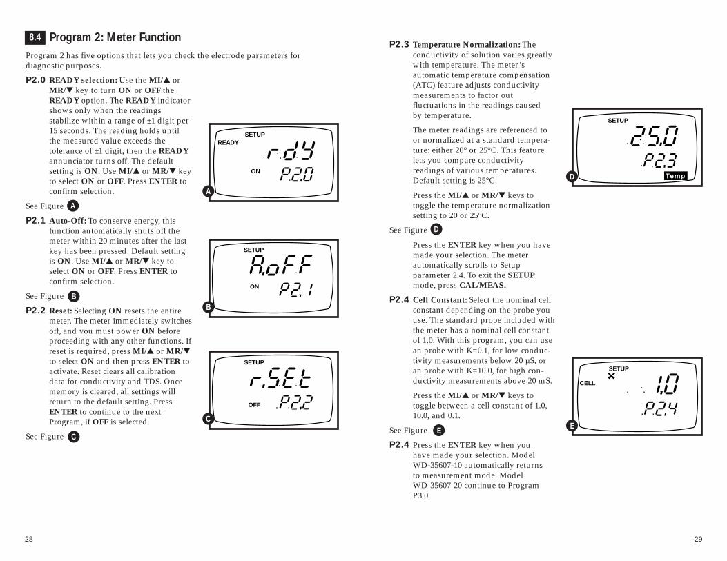
P2.3 Temperature Normalization: The conductivity of solution varies greatlywith temperature. The meter’s automatic temperature compensation(ATC) feature adjusts conductivity measurements to factor out fluctuations in the readings caused by temperature.
P2.3 The meter readings are referenced toor normalized at a standard tempera-ture: either 20° or 25°C. This featurelets you compare conductivity readings of various temperatures.Default setting is 25°C.
P2.3 Press the MI/▲ or MR/▼ keys to toggle the temperature normalizationsetting to 20 or 25°C.
See Figure
P2.3 Press the ENTER key when you havemade your selection. The meter automatically scrolls to Setup parameter 2.4. To exit the SETUPmode, press CAL/MEAS.
P2.4 Cell Constant: Select the nominal cellconstant depending on the probe youuse. The standard probe included withthe meter has a nominal cell constantof 1.0. With this program, you can usean probe with K=0.1, for low conduc-tivity measurements below 20 µS, oran probe with K=10.0, for high con-ductivity measurements above 20 mS.
P2.4 Press the MI/▲ or MR/▼ keys to toggle between a cell constant of 1.0,10.0, and 0.1.
See Figure
P2.4 Press the ENTER key when you have made your selection. Model WD-35607-10 automatically returns to measurement mode. Model WD-35607-20 continue to ProgramP3.0.
Program 2: Meter FunctionProgram 2 has five options that lets you check the electrode parameters for diagnostic purposes.
P2.0 READY selection: Use the MI/▲ orMR/▼ key to turn ON or OFF theREADY option. The READY indicatorshows only when the readings stabilize within a range of ±1 digit per15 seconds. The reading holds untilthe measured value exceeds the tolerance of ±1 digit, then the READYannunciator turns off. The default setting is ON. Use MI/▲ or MR/▼ keyto select ON or OFF. Press ENTER toconfirm selection.
See Figure
P2.1 Auto-Off: To conserve energy, thisfunction automatically shuts off themeter within 20 minutes after the lastkey has been pressed. Default settingis ON. Use MI/▲ or MR/▼ key toselect ON or OFF. Press ENTER toconfirm selection.
See Figure
P2.2 Reset: Selecting ON resets the entiremeter. The meter immediately switchesoff, and you must power ON beforeproceeding with any other functions. Ifreset is required, press MI/▲ or MR/▼to select ON and then press ENTER to activate. Reset clears all calibrationdata for conductivity and TDS. Oncememory is cleared, all settings willreturn to the default setting. PressENTER to continue to the next Program, if OFF is selected.
See Figure
READYSETUP
ON
A
SETUP
ON
B
SETUP
OFF
C
Temp
SETUP
D
SETUP
CELL
E
8.4
A
B
C
D
E

3130
Program 4: Communication Set-Up (WD-35607-20 only)Program 4 has three options that lets youset up the meter communication parameters when operating with eitheryour optional printer or PC. Set theseoptions to match your printer or PCrequirements.
P4.0 Baud Rate: Press MI/▲ or MR/▼ toselect a baud rate of 2.4, 4.8, 9.6, or19.2 Kbps (2400, 48000, 9600, or 19200bps). The default setting is 9.6 Kbps(9600 bps). Press ENTER.
See Figure
P4.1 Parity: Press MI/▲ or MR/▼ to selectparity of 1, 2, or 0. Default setting
is 2 (EVEN). Press ENTER.
See Figure
P4.2 Stop Bit: Press MI/▲ or MR/▼ toselect the stop bit to be 1 or 2. Default setting is 2. Press ENTER.
See Figure
P3.1 The meter automatically returns tomeasurement mode.
SETUP
A
SETUP
B
SETUP
C
8.6
A
B
C
Program 3: TDS Function (WD-35607-20 only)Program 3 has two options for customizing.
P3.0 Conductivity to TDS Conversion factor: Press MI/▲ or MR/▼ toincrease or decrease the conductivityto TDS conversion factor. You canadjust the value from 0.4 to 1.0. Valuesless than 0.4 or greater 1.0 will causethe “ERR” indicator to flash. Thedefault setting is 0.5. Press the ENTERkey to confirm your selection andmove to the next program.
See Figure
Note: The Conductivity to TDS Conversion Factor for a particular solution is a mul-tiplication factor that relates the measurement of conductivity in µS/cm (ormS/cm) to its equivalent reading in ppm (or ppt) This factor is unique for aspecific solution. If you do not know the conversion factor for your solutionsee the table in Addendum 1, page 52. Many Conductivity CalibrationSolutions will list conversion factors on their labels. For the highest accuracyin your specific sample solution, see the method and calculation given inAddendum 2, page 53.
P3.1 TDS Measuring Units: Use the MI/▲or MR/▼ to select ppm (and ppt) ormg/l (and g/l). The default setting isppm. Press ENTER to confirm selection.
See Figure
P3.1 Model WD-35607-20 automaticallycontinues to Program P4.0.
TDS
SETUP
ppm
TDS
SETUP
8.5
A
B
A
B
3332
9. Optional Printer and RS-232 Output Setup
This section is for CON 200 model WD-35607-20 only (model with RS-232 capabilities). Meters with RS-232 provide an output for transmitting readings to aprinter or computer. The data is supplied in ASCII format. ASCII format allows datato be imported into most popular software programs, and to most printers.
Using with OAKTON Printer WD-35622-00See Printer manual for more details
1. Connect cable WD-35622-00 from printer to meter.
2. Configure printer for Portable Conductivity/TDS meter.
3. Press PRINT key ( )
Using with a Non-OAKTON Printer
Minimum printer requirements to print data:
• A 9 pin RS-232 serial port on printer.• Printer should have the option to receive 8 data bits; even (2), odd (1) or
none (0) parity bits; and 1 or 2 stop bits.
NOTE: To print data, connect the meter directly to the printer. You do not need toconnect the meter to the computer.
9.1
9.2
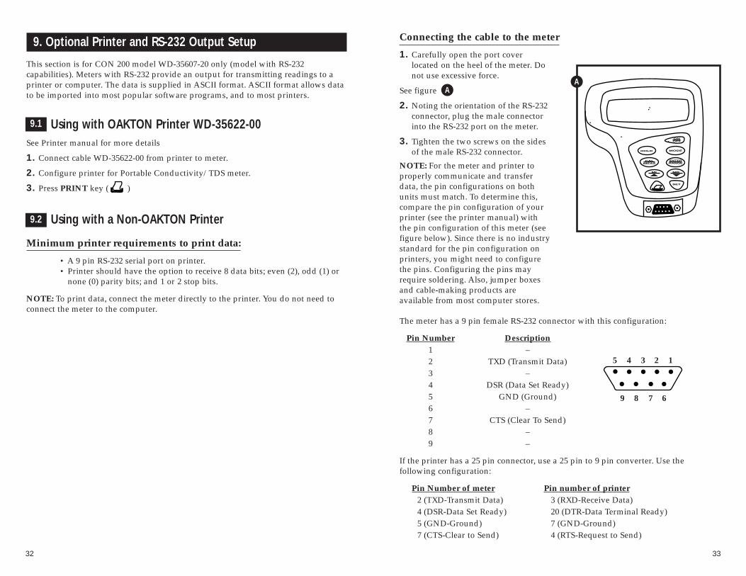
Connecting the cable to the meter
1. Carefully open the port cover located on the heel of the meter. Donot use excessive force.
See figure
2. Noting the orientation of the RS-232connector, plug the male connectorinto the RS-232 port on the meter.
3. Tighten the two screws on the sidesof the male RS-232 connector.
NOTE: For the meter and printer toproperly communicate and transferdata, the pin configurations on bothunits must match. To determine this,compare the pin configuration of yourprinter (see the printer manual) withthe pin configuration of this meter (seefigure below). Since there is no industrystandard for the pin configuration onprinters, you might need to configurethe pins. Configuring the pins mayrequire soldering. Also, jumper boxesand cable-making products are available from most computer stores.
The meter has a 9 pin female RS-232 connector with this configuration:
Pin Number Description1 –2 TXD (Transmit Data)3 –4 DSR (Data Set Ready)5 GND (Ground)6 –7 CTS (Clear To Send)8 –9 –
If the printer has a 25 pin connector, use a 25 pin to 9 pin converter. Use the following configuration:
Pin Number of meter Pin number of printer2 (TXD-Transmit Data) 3 (RXD-Receive Data)4 (DSR-Data Set Ready) 20 (DTR-Data Terminal Ready)5 (GND-Ground) 7 (GND-Ground)7 (CTS-Clear to Send) 4 (RTS-Request to Send)
A
5 4 3 2 1
9 8 7 6
A
3534
Preparing the printer
Set printer to match the meters RS-232 parameters as set in SETUP Program 4, P4.0,P4.1, and P4.2 on page 31 (consult the printer manual for specifications).
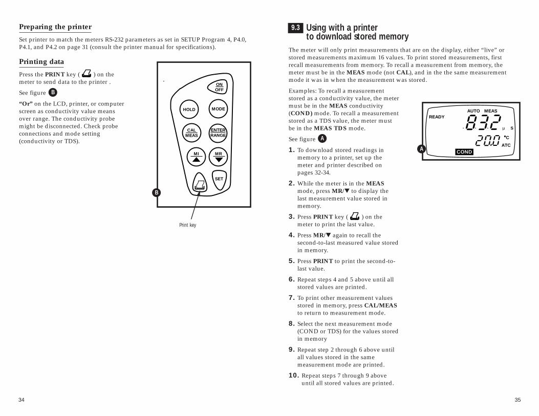
Printing data
Press the PRINT key ( ) on themeter to send data to the printer .
See figure
“Or” on the LCD, printer, or computerscreen as conductivity value meansover range. The conductivity probemight be disconnected. Check probeconnections and mode setting (conductivity or TDS).
B
Using with a printer to download stored memory
The meter will only print measurements that are on the display, either “live” orstored measurements maximum 16 values. To print stored measurements, firstrecall measurements from memory. To recall a measurement from memory, themeter must be in the MEAS mode (not CAL), and in the the same measurementmode it was in when the measurement was stored.
Examples: To recall a measurementstored as a conductivity value, the metermust be in the MEAS conductivity(COND) mode. To recall a measurementstored as a TDS value, the meter mustbe in the MEAS TDS mode.
See figure
1. To download stored readings inmemory to a printer, set up the meter and printer described on pages 32-34.
2. While the meter is in the MEASmode, press MR/▼ to display thelast measurement value stored in memory.
3. Press PRINT key ( ) on themeter to print the last value.
4. Press MR/▼ again to recall the second-to-last measured value storedin memory.
5. Press PRINT to print the second-to-last value.
6. Repeat steps 4 and 5 above until allstored values are printed.
7. To print other measurement valuesstored in memory, press CAL/MEASto return to measurement mode.
8. Select the next measurement mode(COND or TDS) for the values storedin memory
9. Repeat step 2 through 6 above untilall values stored in the same measurement mode are printed.
10. Repeat steps 7 through 9 aboveuntil all stored values are printed.
C
ATC
READYMEAS
COND
AUTO
µ S
A
9.3
A
HOLD
ONOFF
CALMEAS
MODE
SET
MI MR
ENTERRANGE
Print key
B

3736
Using with a Computer and the OAKTON Datalog Assist Software
Minimum Computer Requirements to run software:
• IBM®PC/XT/AT® or 100% compatible (DOS 3.0 or later)
• 640K RAM memory
• Monitor
• RS-232 serial port
• 31⁄2” floppy disk drive
The OAKTON Datalog Assist Software is a very basic data acquisition software thatprovides a convenient way to capture data for future analysis. Data is stored in theASCII format. This allows the data to be transferred to a variety of popular softwareprograms. The disk includes three programs:
README BAT: simply type README to see the content of theREADME.DOC file.
ONDATA EXE: the data acquisition software.
README DOC: is a program that describes what the ONDATA andDEMO programs do.
To see this list, type “DIR” at the DOS prompt for directory. Data files will alsoappear on the directory as they are created.
Connecting the cable to the meter
1. Carefully open the port cover located on the heel of the meter. Donot use excessive force.
See figure
2. Noting the orientation of the RS-232connector, plug the male connectorinto the RS-232 port on the meter.
3. Tighten the two screws on the sidesof the male RS-232 connector.
9.4
BB
Connecting the cable to the computer
1. Locate the port on the computer.
2. Noting the orientation of the RS-232 connector, plug the male connector into theRS-232 port on the computer.
3. Tighten the two screws on the sides of the male RS-232 connector.
4. If the computer has a 25 pin connector, you will need a 25 pin to 9 pin adapter.
Loading the OAKTON Datalog Assist Software
1. Turn on computer.
2. Insert the 3 1⁄2” disk provided with the meter into the floppy disk drive on thecomputer. See the computer instruction manual to locate the drive. Be sure “writeprotect” on disk is off or unlocked.
3. To boot the software
from DOS, type “ONDATA”, the name of the data acquisition program.You can also type “DIR” at the DOS prompt. “DIR” will show you thedirectory of the programs on the disk. To enter the data acquisition pro-gram, type “ONDATA” at the DOS prompt. At the A:\ type “RUN ONDATA”
from Windows Program Manager, select “RUN” and enter the file name“ONDATA”.
from Windows 95, taskbar select “START” and “RUN”. Click the“BROWSE” button. Find and select the “ONDATA” file on your A:\ drive.

3938
Setting the communication parameters
The meter is capable of different communication configurations for baud rate, paritybits and stop bits. The values chosen for these parameters for the meter must matchthose chosen for the computer.
After entering ONDATA as stated on page 37, a blank screen appears where themeasurement data will go. The following screen will appear:
1. Push F1 to enter the HELP program. The first screen of HELP explains the function keys used in the SETUP program.
Push either “Page Up” or “Page Down” to advance to the second screen of HELP.This screen indicates the proper file name extensions that you must use when namingfiles (done in the SETUP program) that will be imported into other software pro-grams. No extension is needed if you are not importing the data into another program.
2. Push ESC to exit the HELP program.

4140
3. Push F5 to enter the SETUP program. You will see the following:
You may select from the following settings:
Baud rate : 2400, 4800, 9600, 19200Parity bit : NONE (0), ODD (1), EVEN (2)Stop bit : 1, 2Com port : 1, 2
(the Com port is communication port that the cable is hooked to on the computer)
4. Set each parameter to the same value as the value chosen in the SETUP programof the meter. To set these parameters in the meter, see SETUP mode, Program 4on page 31 of this manual for complete instructions. Use the “+” key to togglebetween the choices for each parameter.
5. After choosing a value for a parameter, push the “TAB” key to move to the nextline. Continue until all parameters (baud rate, parity bit, stop bit and com port)are chosen. Push “TAB” to move to the next line, “Enter file name.”
6. Enter a file name. If the data will be imported into another software program, usethe proper file extension as shown on the second screen of HELP. The entire filename, including the period and three-letter extension (for example “.PRN” forLotus 1-2-3®), can be maximum of 12 characters. If the data will not be importedinto another software program, then a file extension is not required. Push “enter”to enter the file name.
7. Push F3 to save the parameters and the file name, and to exit the SETUPprogram. The file name will be listed in the directory.IMPORTANT: If you exit this program by pressing Esc instead of F3, all informa-tion just selected will be lost. All parameters and the file name will convert backto those that had been shown when you first entered the SETUP program.
8. No matter which key you pressed to exit the SETUP program (either F3 or ESC),the ONDATA screen will now appear.
Sending data to the computer1. Press the PRINT key ( ) on the meter to send data to the computer.
See figure
2. The data appears on the ONDATA computer screen as follows:
Note: If your meter is set for TDS measurement the screen will show “TDS” instead of “COND”.
3. Continue to push PRINT on the meter to send data to the computer.
4. When all data has been collected, push ESC to quit the ONDATA program.
HOLD
ONOFF
CALMEAS
MODE
SET
MI MR
ENTERRANGE
Print key
A
9.5
A

4342
Using with a Computer and the OAKTON Datalog AssistSoftware to Download Stored Memory
The meter will only send measurements to the computer that are on the display,either “live” or stored measurements. To download stored measurements, first recallmeasurements form memory. To recall a measurement from memory, the meter mustbe in the MEAS mode (not CAL), and in the same measurement mode it was inwhen the measurement was stored. Date and time of measurement are not stored.When downloading stored measurements, the date and time on screen will be thecurrent date and time.
EXAMPLES: To recall a measurementstored as a conductivity value, the metermust be in the MEAS conductivity(COND) mode. To recall a measurementstored as a TDS value, the meter must bein the MEAS TDS mode.
See Figure C
ATC
READYMEAS
COND
AUTO
µ S
B
1. To download stored readings in memory to a computer, set up the meter andcomputer as described on pages 31-36 of this manual.
2. While the meter is in the MEAS mode, press MR to display the last measuredvalue stored in memory.
3. Press PRINT key ( ) on the meter to send the last value to the computer.
4. Press MR again to recall the second-to-last value.
5. Press PRINT key ( ) on the meter to send the second-to-last value to the computer.
6. Repeat steps 4 and 5 above until all measurement values stored are sent to thecomputer.
7. To send other measurement values stored in memory to the computer, pressCAL/MEAS to return to the measurement mode.
8. Select the next measurement mode (COND or TDS) for the measurement valuesstored in memory.
9. Repeat steps 2 through 5 above until all values stored in the same measurementmode are downloaded to the computer.
10. Repeat steps 7 through 9 above until all measurement values stored in memoryare downloaded.
B
9.6 Viewing a Data File1. To view a data file, type “type”, followed by a space, and the file name at the
DOS prompt. The contents of the file will appear, but you will not be able tochange the data.
2. To view a data file and change any information in the file, type “edit”, followedby a space, and the file name at the DOS prompt. The contents of the file willappear. Use the arrow keys on the computer to move the cursor around.
3. To quit, press ESC. If you made change to the file, the computer will ask if youwant to save the change. Press Y for yes and N for no.
Printing ErrorsIf the LCD shows “ERR”, the print annunciator blinks or the meter prints or down-loads garbled data, or prints or downloads nothing; the printer or computer mightnot be connected properly; check cable connections. Also, the dip switch settingcould be set wrong. Check dip switches for baud rate, data bits, and parity.
9.7
9.8
11. Probe Replacement
Your meter and probe have been factory calibrated to each other for maximum accuracy. If you notice a reduction in accuracy after replacing your probe, perform a zero calibration and two-point temperature calibration.
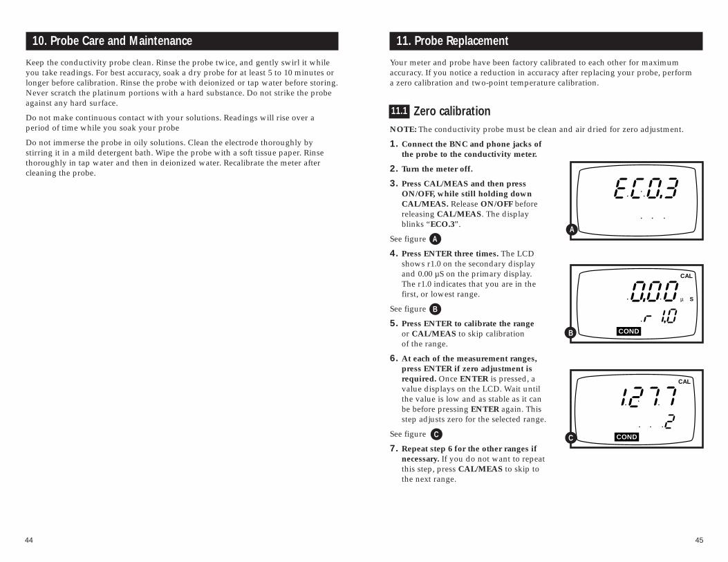
Zero calibrationNOTE: The conductivity probe must be clean and air dried for zero adjustment.
1. Connect the BNC and phone jacks ofthe probe to the conductivity meter.
2. Turn the meter off.
3. Press CAL/MEAS and then pressON/OFF, while still holding downCAL/MEAS. Release ON/OFF beforereleasing CAL/MEAS. The displayblinks “ECO.3”.
See figure
4. Press ENTER three times. The LCDshows r1.0 on the secondary displayand 0.00 µS on the primary display.The r1.0 indicates that you are in thefirst, or lowest range.
See figure
5. Press ENTER to calibrate the rangeor CAL/MEAS to skip calibration of the range.
6. At each of the measurement ranges,press ENTER if zero adjustment isrequired. Once ENTER is pressed, avalue displays on the LCD. Wait untilthe value is low and as stable as it canbe before pressing ENTER again. Thisstep adjusts zero for the selected range.
See figure
7. Repeat step 6 for the other ranges if necessary. If you do not want to repeat this step, press CAL/MEAS to skip to the next range.
4544
10. Probe Care and Maintenance
Keep the conductivity probe clean. Rinse the probe twice, and gently swirl it whileyou take readings. For best accuracy, soak a dry probe for at least 5 to 10 minutes orlonger before calibration. Rinse the probe with deionized or tap water before storing.Never scratch the platinum portions with a hard substance. Do not strike the probeagainst any hard surface.
Do not make continuous contact with your solutions. Readings will rise over a period of time while you soak your probe
Do not immerse the probe in oily solutions. Clean the electrode thoroughly by stirring it in a mild detergent bath. Wipe the probe with a soft tissue paper. Rinsethoroughly in tap water and then in deionized water. Recalibrate the meter aftercleaning the probe.
COND
CAL
C
COND
CAL
µ S
B
AA
B
C
11.1

4746
12. Troubleshooting
Problem Cause Solution
Power on but a) Batteries not in place. a) Check that batteries are inno display place and making good
contact.
b) Batteries not in correct b) Re-insert batteries withpolarity (+ and –). correct polarity.
c) Weak batteries. c) Replace batteries or attach optional AC adapter.
Unstable a) Air bubbles in probe. a) Tap probe to remove bubbles.readings b) Dirty probe. b) Clean the probe and
recalibrate.
c) Low conductivity. c) Avoid atmospheric contact with solution.
d) Probe not deep d) Make sure sample entirelyenough in sample. covers the probe sensors.
e) External noise pickup e) Move or switch offor induction caused by interfering motor (or noise).nearby electric motor.
f) Broken probe. f) Replace probe. See page 50.
Not able to a) Dirty/Oily probe. a) Clean probe. See "Probe calibrate Care & Maintenance",
page 44.
b) Incorrect TDS factor in b) Set proper TDS factor prior TDS mode (TDS models). calibration, see SETUP
section Program3, P3.0 on page 30 for instructions.
c) Incorrect probe cell c) Replace probe or set meter toconstant. correct probe cell constant
see SETUP section Program 2P2.4 on page 29.
“Or” on LCD, a) Probe is shorted. a) Check or replace probe printer or (see page 50)computer screen
b) Conductivity of solution b) Choose a conductivity probe is too high for probe. with a higher cell constant
(K) see page 50 or use a different solution.
Two point temperature calibrationAfter zero calibration, the meter proceeds to program 6.0, for temperature calibrationof the probe. The temperature in °C shows in the primary display and “r6.0” showsin the secondary display.
See figure
1. Press CAL/MEAS until the meter automatically switches off to skip thissection of the calibration. Do NOTpress ENTER unless you have completed the steps below. PressingENTER replaces current temperaturecalibration data and causes measurement errors.
2. Prepare two constant temperaturebaths, one at a temperature below 5°C(low temperature bath) and the other atbetween 50°C to 60°C (high temperature bath).
3. Dip the probe into the low temperaturebath. Allow 5 to 10 minutes for theprobe to stabilize.
4. Press the ▲ or ▼ keys to fine tunetemperature reading to match bathtemperature.
5. Press ENTER. The screen now showsthe A-to-D count corresponding toyour low temperature calibration point.This is a five digit number with thefirst digit appearing in the secondarydisplay and the rest of the digits in theprimary display. In our example atright, the A-to-D count is 13490.
See figure
6. Let the count stabilize, then pressENTER again. This confirms your lowtemperature calibration point, and movesyou into high temperature calibration(“r6.1) If you do not want to confirmyour calibration, press CAL/MEAS.
7. Repeat steps 4-6 with high temperature bath.
NOTE: To exit from the hardware calibration at any point, press ON/OFF to switchoff the meter and abort the calibration. Only calibration points that havebeen confirmed by pressing ENTER will be retained.
CAL
TempA
CAL
TempB
A
B
11.2

4948
14. Specifications
Mode Conductivity TDS Temperature
0.00 to 19.99 µS0.00 to 9.99 ppm
0.0 to 199.9 µS10.0 to 99.9 ppm 0.0 to 80.0°C
Range 0 to 1999 µS100 to 999 ppm (with epoxy platinum probe)
0.00 to 19.99 mS1.00 to 9.99 ppt 0.0 to 100.0°C10.0 to 99.9 ppt (with glass/platinum probe)
0.0 to 199.9 mS 100 to 200 ppt
0.01 µS0.01 ppm
0.1 µS0.1 ppm
Resolution 1 µS1 ppm 0.1°C
0.01 mS0.01 ppt0.1 ppt
0.1 mS 1 ppt
Accuracy ±1% Full Scale ±1% Full Scale ±0.5°C
Calibration Up to five points Up to five points Offset in 0.1° increments(one point per range) (one point per range)
Temperature compensation: automatic (ATC) or manual from 0 to 100°C
Temperature Coefficient Adjustment: 0.0 to 10.0% per °C
Cell constant: 1 with probe supplied. Cell constant of 0.1 is best for very low ranges(<10 µS) and a cell constant pf 10 is best for higher ranges (100 mS).
Operating temperature: 0 to 50°C
RS-232 Communication (models WD-35607-20 only): 9 pin female, select baud rates2.4, 4.8, 9.6, and 19.2 kbps (2400, 4800, 9600, 19200 bps); stop bit and parity
Power: four 1.5 V AAA batteries (included) or AC adapter (optional; order separately on page 50)
Battery life: > 60 hours
Dimensions: Meter: 7.5"L x 3.5"W x 1.75"H (19.1 cm x 8.9 cm x 4.5 cm)
Boxed: 9.2"L x 8.5"W x 2.75"H(23.3 cm x 21.6 cm x 7 cm)
Probe: 5.0"L x 0.5"dia with 2.5 ft cable(100 mm L x 12 mm dia with 0.9 m cable)
Shipping weight: 2 lbs (0.9 kg)
13. Error Messages
LCD Indicates Cause SolutionDisplay
Err Unrecognized input Wrong input in Release key. Select annunciator from keypad selected mode. valid operations
depending on mode.
CAL & Err Calibration error Wrong value input Check your calibration annunciators at calibration. input value, clean probe.blink Dirty probe. See Calibration sections or
Probe Maintenance section.
Battery Low battery level Need new batteries Clean battery contacts.indicator blinks or battery Replace batteries with fresh
connection is bad ones, noting polarity
Err annunciator Unable to print or Printer/computer Turn printer/computer on, & printer send data to is off, cable is check cable connections, or indicator computer unplugged or . check printer/computer blinks cable is faulty settings on both the meter
and receiving device.
Err. 1 Memory write Instrument too Turn meter on and off(in primary error old (>10 years). again. If message persists, display) Hardware failure return unit*
Err. 2 Memory checksum Hardware failure. Turn meter on and off(in primary error again. If message persists, display) return unit*
Err. 3 ACD converter Hardware failure. Turn meter on and off(in primary error again. If message persists, display) return unit*
Err. 4 Keypad error Fault in keypad Turn meter on and off(in primary again. If message persists, display) return unit*
* See "Warranty" and "Return of Items" on page 59
If an error message appears in the primary display (the upper row of larger digits), switching off the meter and switching it onagain may eliminate the error message.
See figure
If error persists, or the meter shows incorrect values, return the meter.
For a complete diagram of the display, seepage 4.
ERR 1 in primary display
AA

5150
OAKTON conductivity calibration solutions (continued from page 50)
WD-00653-18 1413 µS calibration solution, 1 pint
WD-00653-15 1500 µS calibration solution, 1 pint
WD-00653-27 2070 µS calibration solution, 1 pint
WD-00653-20 2764 µS calibration solution, 1 pint
WD-00653-89 8974 µS calibration solution, 1 pint
WD-00060-10 12880 µS calibration solution, 1 pint
WD-00653-50 15,000 µS calibration solution, 1 pint
WD-00653-32 80 mS calibration solution, 1 pint
OAKTON “Singles” calibration solution pouches
WD-35653-00 Deionized rinse water solution pouches, 20/box.
WD-35653-10 447 µS calibration solution pouches, 20/box.
WD-35653-11 1413 µS calibration solution pouches, 20/box.
WD-35653-12 2764 µS calibration solution pouches, 20/box.
WD-35653-13 15,000 µS calibration solution pouches, 20/box.
Consult your OAKTON® Distributor for a complete selection of conductivity/TDScells, solutions, holders, and accessories. Ask for bulletin Accessories A5.
To order OAKTON accessories, contact your OAKTON distributor.
15. Accessories
Replacement probes and accessories
WD-35615-09 RS-232/Printer cable, 9- pin male for units with RS-232 printer output.
WD-35615-07 AC adapter, 9 VDC to 110 VAC.
WD-35615-08 AC adapter, 9 VDC to 220 VAC.
WD-35615-75 Belt loop portable meter carrying case. Soft case with clear plasticfront panel protects your meter while allowing you to take measurements. Topand side openings let probe and probe connections remain accessible.
WD-35607-60 Conductivity/TDS Calibration Kit (meter not included). Includes 60 mL of four calibration solutions (84 µS, 447 µS, 15,000 µS, and 80 mS), a squirt bottle with 120 mL deionized water, and a 60-ml sample bottleall secured in a hard carrying case.
WD-35615-06 Replacement electrode holder.
WD-35607-50 Replacement conductivity cell. Epoxy body/platinum sensor withbuilt-in temperature sensor. K = 1.0.
WD-35607-52 Portable conductivity cell. Glass body/platinum sensor with built-intemperature sensor. K = 1.0.
WD-35607-51 Portable conductivity cell. Epoxy body/platinum sensor with built-intemperature sensor. K = 10.
WD-35607-53 Portable conductivity cell. Glass body/platinum sensor with built-intemperature sensor. K = 10.
WD-35607-55 Portable conductivity cell. Epoxy body/platinum sensor with built-intemperature sensor. K = 0.1.
WD-35607-56 Portable conductivity cell. Glass body/platinum sensor with built-intemperature sensor. K = 0.1.
WD-35607-54 Flow-through conductivity cell. Glass body/platinum sensor withbuilt-in temperature sensor. K = 1.0. Use for continuous in-line measurement forflows up to 1 gal/minute and pressures up to 80 psi.
OAKTON conductivity calibration solutions
Conductivity solutions have ±1% accuracy at 25°C. Shpg wt 1.1 lb (510 g). SeeAddendum 1, page 51 for TDS values for the solutions below.
WD-00653-23 23 µS calibration solution, 1 pint
WD-00653-16 84 µS calibration solution, 1 pint
WD-00653-47 447 µS calibration solution, 1 pint

5352
17. Addendum 2: Calculating TDS Conversion Factors
The meter can be calibrated using TDS calibration standard solutions. The calibrationstandard only needs to give the TDS value at a standard temperature such as 25°C.To determine to the conductivity-to-TDS conversion factor use the following formula:
Factor = Actual TDS ÷ Actual Conductivity @ 25°C
Definitions:
Actual TDS: Value from the solution bottle label or as a standard you make usinghigh purity water and precisely weighed salts.
Actual Conductivity: Value measured using a properly calibrated OAKTON Conductivity/TDS/Temperature meter.
Both the Actual TDS and the Actual Conductivity values must be in the same magnitude of units. For example, if the TDS value is in ppm the conductivity valuemust be in µS; if the TDS value is in ppt the conductivity value must be in mS.
Check this number by multiplying the conductivity reading by the factor in theabove formula and the result is the TDS in ppm.
16. A
dden
dum
1:
Cond
uctiv
ity to
TD
S Co
nver
sion
Fact
ors
1.
Fact
or—
the
cond
ucti
vity
to p
pm T
DS
conv
ersi
on f
acto
r. M
ulti
ply
cond
ucti
vity
by
this
fac
tor
to g
et p
pm T
DS
for
the
type
of
TD
Sre
adin
g ne
eded
. E
nter
this
fac
tor
into
you
r O
AK
TON
TD
S/co
nduc
tivi
ty m
eter
in S
etup
, Pro
gram
3, P
3.0
on p
age
30.
The
met
erau
tom
atic
ally
giv
es th
e m
ost a
ccur
ate
TD
S re
adin
gs.
2.
442—
a fo
rmul
atio
n th
at m
ost c
lose
ly r
epre
sent
s th
e co
nduc
tivi
ty to
ppm
rel
atio
nshi
p, o
n av
erag
e, f
or n
atur
ally
occ
urri
ng f
resh
wat
er.
3.
TD
S Y
our
Mat
eria
l—T
hese
col
umns
are
for
you
to w
rite
in y
our
appl
icat
ion
spec
ific
con
duc
tivi
ty to
ppm
val
ues
and
con
vers
ion
fact
ors
for
futu
re r
efer
ence
. Se
e pa
ge 5
3.
Fact
or =
act
ual
TD
S ÷
Act
ual
Con
du
ctiv
ity
@ 2
5°C
Con
du
ctiv
ity
TD
S K
Cl
TD
S N
aCl
TD
S 4
42 2
TD
S Y
our
Mat
eria
l 3
at 2
5°C
pp
m
Fact
or 1
pp
m
Fact
or 1
pp
m
Fact
or 1
pp
mFa
ctor
Val
ue
Val
ue
Val
ue
Val
ue
23 µ
S11
.60
0.50
4410
.69
0.46
5214
.74
0.64
09
84 µ
S40
.38
0.50
4838
.04
0.47
5550
.50
0.65
63
447
µS22
5.6
0.50
4721
5.5
0.48
2230
0.0
0.67
12
1413
µS
744.
70.
5270
702.
10.
4969
1000
0.70
78
1500
µS
757.
10.
5047
737.
10.
4914
1050
0.70
00
2070
µS
1045
0.50
4710
410.
5030
1500
0.72
46
2764
µS
1382
0.50
0014
150.
5119
2063
0.74
63
8974
µS
5101
0.56
8544
870.
5000
7608
0.84
78
1288
0 µS
7447
0.57
8272
300.
5613
11,3
670.
8825
1500
0 µS
8759
0.58
3985
320.
5688
13,4
550.
8970
80 m
S52
,168
0.65
2148
,384
0.60
4879
,688
0.99
61

5554
19. Addendum 4: Calibration Tips
You only need one calibration for measurement throughout the entire range of themeter. If a range was not calibrated, the meter automatically detects the closest rangecalibrated and uses that calibration information. However, only the ranges that werecalibrated have maximum accuracy.
If you are measuring in ranges greater than 20 mS or conductivity lower than 100 µS, calibrate the meter at least once a week to get specified ±1% F.S. accuracy. Ifyou are measuring in the mid ranges and you washed the probe in deionized waterand stored it dry, calibrate the meter at least once a month. Wet the probe for 10 minutes before calibrating or taking readings to saturate the probe surface and minimize drift. If you make measurements at extreme temperatures, calibrate themeter at least once a week.
Use only the conductivity/TDS probe specified for these meters. If you do not, youmust measure the solution temperature separately and manually enter the solutiontemperature.
18. Addendum 3: Calculating Temperature Coefficients
To determine the temperature coefficient of your sample solution use this formula:
CT2 - CT1TC = 100 x _________________________CT1(T2 - 25) - CT2(T1 - 25)
TC = Temperature coefficient
CT1 =Conductivity at Temp. 1 CT2 = Conductivity at Temp. 2
T1 = Temp. 1 T2 = Temp. 2, 25 = 25°C
NOTE: A controlled temperature water bath is ideal for this procedure.
1. Immerse the probe into a sample of solution and adjust the temperature coefficient to 0% (that is, no compensation) by entering setup Program 1, P1.1 seepage 26 and pressing the MR/▼ button until the upper display shows 0.0 andpress ENTER. Press CAL/MEAS to come back to conductivity measurements.
2. Wait for 5 minutes. Note T1 and CT1 (conductivity at T1).
3. Condition the sample and probe to a temperature (T2°C) that is about 5°C to 10°Cdifferent from T1, and note the conductivity reading CT2.
NOTE: Record your results for future reference in the back of this manual. Ideally T1and T2 should bracket your measurement temperature, and should not differby more than 5°C.
4. Enter the Temperature Coefficient in the meter. While in Program 1, P1.1 on page26, use MI/▲ or MR/▼.
5. Scroll to a required value from 0.0 to 10.0%/°C as determined in the procedureoutlined above or in Section 4, Calibration on page 11-12.
6. Once this value is displayed, press ENTER to confirm the value. This coefficientwill now be applied to all the meter readings.