
O-ring basics from C. Otto · PDF fileIndex of Contents General 4 (Description, materials)...
32
O-KROUŽKY
Transcript of O-ring basics from C. Otto · PDF fileIndex of Contents General 4 (Description, materials)...

©20
07 C
.Ott
o G
ehrc
kens
Gm
bH &
Co.
KG
. Vyh
razu
jem
e si
prá
vo c
hyb
a zm
ěny.
O-KROUŽKY

� COG
FOR THEBENEFIT OF OUR CLIENTS
Founded in 1867 in Pinneberg near Hamburg +++ Independent family-owned company with
approximately 170 employees +++ Europe‘s largest O-ring warehouse (over 40,000 items in
stock) Tools for over 14,000 O-ring sizes +++ Own mixing facilities and mixture development
+++ Close cooperation with leading raw materials makers +++ Releases and certifications of
various materials to hand +++ Own tool making +++ Optimised delivery service using our new
logistics centre opened in �00� +++ Quality management to DIN EN ISO 9001 standards +++
Environmental management to DIN EN ISO 14001 standards
C. Otto Gehrckens - abbreviated COG - has offered its client
uncompromising premium quality for 140 years. Tradition
and innovation are a single potent entity at COG and the key
to success. This is demonstrated daily in our customer rela-
tions. Our clients are the among the best in their respective
industries. And they expect the best from us.
Over 170 employees are committed at COG to our clients‘
success, ranging from engineers in the applicastion tech-
nology department to our colleagues in Europe‘s largest
O-ring warehouse with their rapid response capabilities. As
an independent manufacturer based in Pinneberg near
Hamburg, managed by the fifth generation of the founding
family, we are a leading supplier of precision O-rings thanks
to our compehensive stock, flexible production facilities and
customer service commitment.

�Index of Contents
General 4(Description, materials)
Natural rubber nomenclature 6
Natural rubber and its trade names 7
O-ring function 8
Hardness 9
Pressure loading 10(O-ring behaviour under pressure)
Thermal characteristics 11
Media resistance 12
Groove geometry for installation spaces 13(Groove depth and width)
Definition of installation types 14
Piston seal 15
Rod seal 18
Flange seals 20
Trapezoidal groove 23
Triangular groove 23
Installation instructions 24
Surface roughness 25
Installation spaces for PTFE O-rings 26
O-ring storage 27
Surface treatment 28
O-RING basics
Our clients define the aims of everything we do.
New ideas and products are developed quickly
and in a market- and goal-oriented manner in
close cooperation with Application Technology
and Sales. The result is often a major market
benefit to our clients. Please refer to www.cog.de
or contact us directly for more information. Let‘s
discuss your aims.
For further information please contact
our Application Technology
on +49 (0)4101 50 0�-�6 oder -704

4 O-ring basics
GeneralAn O-ring seal is a means of preventing
unwanted lekagae or loss of fluid or gas (i.e.
media generally).
The O-ring is the most popular form of seal as
it’s so easy and simple to install and needs little
installation space. Given correct grooving and
material/s choice the seal can be used for a
very long time within the rubber’s temperature
limits both as a fixed and as a moving part.
Description
An O-ring is a closed circle usually made of
flexible rubber (elastomer). The dimensions are
defined by the interior diameter d1 and the cord
diameter d2.
O-ring-sizing
O-rings are gaplessly and seamlessly made of
various types of natural rubber in hot injection or
press moulds by vulcanising (cross-linking).
Manufacturing processes
Two manufacturing processes are fundamentally
differentiated between in manufacturing O-rings
of elastomers.
• Compression process
(Compression moulding = CM-process)
• Injection moulding
(Injection moulding = IM-process)
In CM the slug is manually inserted in the tool
(mould) before the two mould halves consisting
of an upper and a lower part are closed. As this
process is very time-consuming it is primarily
suitable for manufacturing smaller quantities and
larger dimensions.
Picture of CM
Picture of IM
O-ring description
Compression process
Injection moulding
In injection moulding the slug is automatically
injected in the tool, which consists of several
O-ring cavities. This process is particularly suit-
able for large quantities and small dimensions.

5O-ring basics
Elastomers/natural rubber
Cross-linked polymers with typical rubbery
characteristics are called elastomers (rubber).
The unlinked raw product is called natural
rubber and the source is either from rubber
plants or of synthetic manufacture.
Materials
Technical rubber materials are made using
recipes whereby the polymer itself is the
weakest link in chemical resistance in the chain
of mixture ingredients where the media to be
sealed are concerned.
The choice of the right sealant material is often
hence restricted to the choice of basic polymer/s.
However, in practice other influences due to the
recipe used may be of significance such as the
type of cross-linking, the quantity of softener/s
used and the type of filler employed. Polymer tol-
erability alone is hence no guarantee of reliable
sealing but is a major pre.condition of it.
iNOTE:Phr is parts per
hundred of rubber, i.e.
relative to 100 parts of
natural rubber.
Elastomers
Seal materials
The elasticity of the cross-linked products is a
result of cross-linking polymer chains causing
elastomers to revert to shape after subjection to
load. The number of elastomer qualities avail-
able is due to the various natural rubber types
that can be used as a basis for a variety of
materials by employing appropriate recipes.
Picture of the macro molecules of natural rubber
Picture of the macro molecules of rubber
Ingredients Quantity in phr
natural rubber (polymer) 100.0
Filler materials 40.0
Softener/s 10.0
Processing aids 3.0
Ageing prevention media 3.0
Activators 2.5
Cross-linking media 2.0
Accelerator/s 1.5
Mixture ingredients in a sample recipe

6 Das O-Ring 1x1
Natural rubber nomenclatureDIN ISO 16�9
ASTM D 1418
Group Chemical name DIN ISO 1629 ASTM D 1418 COG no.
M Polyacrylate-natural rubber ACM ACM AC …
M Chlorpolyethylene-natural rubber CM CM --
M Ethylene acrylate-natural rubber AEM AEM --
MChlorsulphurated-polyethylene-
natural rubberCSM CSM Hy ...
M Ethylene-propylene-natural rubber EPM EPM EP …
M Ethylene-propylene-(dien)-natural rubber EPDM EPDM AP ...
M Fluoride-natural rubber
FPM FKMLT …
Vi …
FEPM FEPMAF…
Vi …
M Perfluor-natural rubber FFPM FFKM Perlast®
O Epichlorhydrine-natural rubber CO CO --
O Epichlorhydrin-copolymer-natural rubber ECO ECO --
O Propylenoxide-copolymer-natural rubber GPO GPO --
R Butadiene-natural rubber BR BR --
R Chloroprene-natural rubber CR CR NE …
R Isobutene-isopropene-natural rubber IIR IIR BT ...
R Isoprene-natural rubber IR IR --
R Acrylnitrile-butadiene-natural rubber NBR NBR P ...
RHydrated acrylnitrile-butadiene-
natural rubberHNBR HNBR HNBR ...
R Natural rubber NR NR K ...
R Styrol-butadiene-natural rubber SBR SBR --
Q Fluor-methyl-silicone-natural rubber FVMQ FVMQ Si … FL
Q Methyl-phenyl-silicone-natural rubber PMQ PMQ --
QMethyl-phenyl-vinyl-silicone-
natural rubberPVMQ PVMQ --
Q Methyl-vinyl-silicone-natural rubber VMQ VMQ Si …
Q Methyl-silicone-natural rubber MQ MQ --
U Polyesterurethane-natural rubber AU AU PU …
U Polyetherurethane-natural rubber EU EU EU ...
Overview of the major natural rubber types with brief designation and COG no.
Due to the designation of the numerous synthe-
sis natural rubbers a classification has been
allocated per IS0 1629 or ASTM D 1418. Natural
rubbers in solid form are classified into the
following group based on their polymer chain
chemical composition.

7O-ring basics
The most common natural rubberswith trade names Natural rubber trade names
Basic natural rubber Abbreviation Trade name (selection)
Acrylnitrile-butadiene-natural rubber NBR Perbunan®, Europrene N®, Krynac®
Styrol-butadiene-natural rubber SBR Europrene®, Buna-S®
Hydrated acrylnitrile-butadiene-
natural rubberHNBR Therban®, Zetpol®
Chloroprene-natural rubber CR Baypren®, Neoprene®
Acrylate natural rubber ACM Nipol AR®, Hytemp®, Cyanacryl®
Ethylene acrylate-natural rubber AEM Vamac®
Fluor natural rubber FPM/FKM Viton®, Dai-El®, Tecnoflon®
FEPM Viton® Extreme, Aflas®
Perfluor natural rubber FFKM Kalrez®, Perlast®, Chemraz®
Silicone natural rubber VMQ Elastosil®, Silopren®
Fluor-silicone-natural rubber FVMQ Silastic®
Polyurethane-natural rubber AU/EU Urepan®, Adiprene®
Ethylene-propylene-(dien)-natural
rubberEPM, EPDM Buna EP®, Dutral®, Nordel®
Butyl rubber IIR Esso Butyl®, Polysar Butyl®
Epichlorhydrine-natural rubber ECO Hydrin®
Natural rubber NR Smoked Sheet®, Pale Crepe®
Polyisoprene-natural rubber IR Natsyn®
Overview of some types of natural rubber (incomplete list)
The table below is an overview of some selected
natural rubbers from which elastomer sealant
materials are made with their abbreviations and
a selection of trade names.

8 O-ring basics
The way they workO-ring sealant effect is due to the elastic defor-
mation of the cross-section (cord diameterr d2)
in an appropriately shaped installation space
(groove). The circular cross-section is changed
to elliptical in this installation space and seals
off a gap in the contact or sealing surface and
groove.
Sealing effect is hence due to deformation of
the circular O-ring. Its extent is determined by
groove depth t. The compression forces that
arise due to this deformation make the seal in
the system.
iIMPORTANT:The cord diameter d�
must always exceed
the depth of the
installation space.
O-ring seal effect
Compressed O-ring in installation space under pressure
Compressed O-ring in installation space without pressure
Any pressure of the medium to be sealed
tensions the O-ring additionally and this is ben-
eficial to the seal as its effect is increased
(surface pressure increase).
The pressure presses the O-ring against the
groove flank facing away from that pressure. To
avoid the ring being pressed into the seal gap in
the process this should be as small as possible.
In radial seals a tolerance pairing of H8/f7 should
exist, in axial seals H11/h11.
If not, or if higher pressures are anticipated, then
the material/s chosen should ensure maximum
possible O-ring hardness. Should this not be the
case extrusion may occur and the O-ring be
destroyed.

9O-ring basics
Hardness Hardness here is the resistance of a body to
penetration by a harder body of a specific shape
at a specific pressure over a specific time. It is
measured in Shore or IRHD (International Rub-
ber Hardness Degree) gemessen. Comparable
values are determined using standard samples
and given in Shore A units. For measurements
on finished products IRHD is usual. Hardness
values of finished products deviate from those
of standard samples as their thickness, curved
surface or values measured at the edges are
not comparable and the metrology procedures
differ.
At a cord thickness ≤ 3 mm is meaningful meas-
urement of hardness is only feasible in IRHD
(up to a cord thickness. of 1.6 mm).
The picture below shows the penetrating body
(a pyramid stump) for hardness measurement
in Shore A (DIN 53505).
Hardness The picture below shows the penetrating body
(a sphere) for hardness measurement in IRHD
(DIN ISO 48 CM).
Hardness must be adjusted to e.g. pressure
burden. The softer the elastomer the easier it is
deformed under pressure and pressed into the
gap to be sealed. On the other hand softer elas-
tomer seals at low pressures and between
uneven surfaces due to its greater flexibility.
Hardness measurement in Shore A
Hardness measurement in IRHD
iNOTE:Hardness is not a
quality characteristic
but a characteristic
that plays a role in
sealing.

10 O-ring basics
The extrusion angle is largely determined by the
gap size g between machinery parts. The play
depends on process, manufacturing method,
tolerances influencing play, the breathing of the
parts under pressure and so on.
iIMPORTANT:The gap size should
be as small as
possible.
Extrusion
O-ring behaviour under pressure
Extruded O-ring
O-rings of 90 Shore A hardness permit slightly
larger gaps than standard-O-rings of 70 Shore
A. The table of guide values below of gap sizes
for standard elastomers are maximum values if
the components are centred.
Excessive gaps can e.g. cause elastomer
destruction by extrusion.
Cord thickness d2 to 2 2.01–3 3.01–5 5.01–7 over 7.01
O-ring hardness 70 Shore A
Pressure (bar) Gap g
≤ 35 0.08 0.09 0.10 0.13 0.15
≤ 70 0.05 0.07 0.08 0.09 0.10
≤ 100 0.03 0.04 0.05 0.07 0.08
O-ring hardness 90 Shore A
Pressure (bar) Gap g
≤ 35 0.13 0.15 0.20 0.023 0.25
≤ 70 0.10 0.13 0.15 0.18 0.20
≤ 100 0.07 0.09 0.10 0.13 0.15
≤ 140 0.05 0.07 0.08 0.09 0.10
≤ 175 0.04 0.05 0.07 0.08 0.09
≤ 210 0.03 0.04 0.05 0.07 0.08
≤ 350 0.02 0.03 0.03 0.04 0.04
Gap size for O-ring installation spaces depending on pressure (data in mm)
iNOTE:All data based on
experience and
solely intended as
guidance.
O-ring behaviour under pressure
11O-ring basics
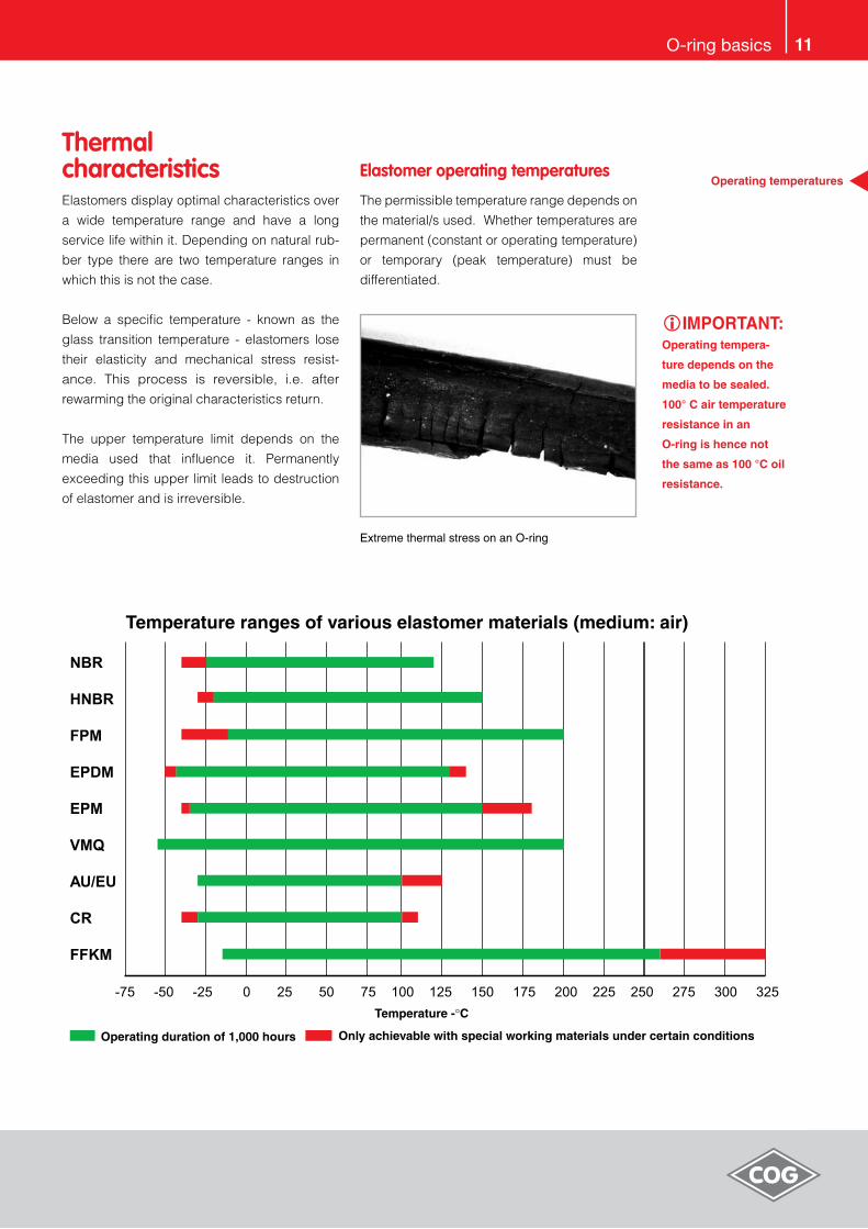
Thermal characteristics Elastomers display optimal characteristics over
a wide temperature range and have a long
service life within it. Depending on natural rub-
ber type there are two temperature ranges in
which this is not the case.
Below a specific temperature - known as the
glass transition temperature - elastomers lose
their elasticity and mechanical stress resist-
ance. This process is reversible, i.e. after
rewarming the original characteristics return.
The upper temperature limit depends on the
media used that influence it. Permanently
exceeding this upper limit leads to destruction
of elastomer and is irreversible.
Operating temperatures Elastomer operating temperatures
The permissible temperature range depends on
the material/s used. Whether temperatures are
permanent (constant or operating temperature)
or temporary (peak temperature) must be
differentiated.
Extreme thermal stress on an O-ring
iIMPORTANT:Operating tempera-
ture depends on the
media to be sealed.
100° C air temperature
resistance in an
O-ring is hence not
the same as 100 °C oil
resistance.

1� O-ring basics
Elastomer resistance to various media is of
major significance. Two types of change occur:
physical and chemical.
Physical processesThis is primarily volume change (swelling or
shrinking) of an elastomer in a medium. In
swelling the elastomer soaks up the medium
and its technical values therefore change (e.g.
lowered tear resistance or hardness). This
doesn’t mean the seal ceases to function. How-
ever, excessive swelling in volume may lead to
the installation space (groove) being overfilled
and the O-ring being mechanically destroyed.
Details of swelling values are given in the litera-
ture on the subject (e.g. COG resistance tables)
or found by practical experiment, which is
better. Please contact us for information.
In shrinking mixture ingredients (e.g. softener)
are separated out of the medium (e.g. mineral
oil). This may lead to seal pressure being too
low or non-existent and result in leakage.
This must be prevented at all costs.
iIMPORTANT:Chemical aggression
and physical shrinka-
ge of an O-ring must
always be prevented/
avoided.
Media resistance
Illustration of chemical aggression on an O-ring
Chemical aggressionContact with the medium here leads to the
destruction of the elastomer as the polymer
chain is changed. This makes the material hard
and brittle and it loses its elastic properties.
Details of chemical resistance can be found
either in the materials specifications, the relevant
literature or resistance tables (e.g. COG resist-
ance tables). Chemical aggression must also be
avoided at all costs.
Elastomer media resistance

1�O-ring basics
O-rings must be laid in grooves made for the
purpose if they are to seal properly.
These installation spaces are usually made with
a rotary chisel in a shaft or drill hole or with a
milling machine in a work piece. Groove geom-
etry is usually rectangular. The illustration below
shows a typical rectangular groove with dimen-
sions as recommended in the relevant
standards.
Illustration of a typical rectangular groove
Nomenclature:
t =groovedepth
b =groovewidth
g =Gaptobesealedsize
P =Mediapressure
A=Opposingsurface
B=Grooveflanksurfaces
andgroovebase
C =Surfaceofinstallationangle
Groove geometry
Groove width b determination
Groove width is determined by O-ring cord
thickness d2 and the elliptical shape after
compression plus a free space in which the
medium can enter to guarantee even pressure
on the seal.
In sizing the groove width the primary criterion
is avoidance of groove overfill. It is therefore
usually assumed in designing the groove that
the O-ring should fill it by up to 85 % so that
there is space for expansion if needed.
Determining groove depth
The relationship of cord thickness d2 of the
O-ring to groove depth determins initial
compression. Choice of groove depth depends
on use. In static use initial compression should
be between 15 and 30 %. In dynamic use a
larger groove depth and smaller hence com-
pression should be chosen, usually between 6
and 20 %.
Groove geometry for O-ring installation spaces
iIMPORTANT:Groove depth is
decisive in O-ring
pressure.
iNOTE:Groove width needs
to be adapted to
possible volume in-
crease of the O-ring.

14
Definition of installation typesThere are various O-ring installation options. O-ring cross-section deformation directions are
differentiated between by axial or radial alignment.
In radial deformation “external seal” (interior groove, piston seal) and “interior seal” (external groove,
rod seal) are also differentiated between. Most O-rings are statically stressed seals. If the seal is
between machinery parts that move toward one another then the seal is dynamic. O-rings are
technically optimal solutions in dynamic sealing only in exceptional cases.
O-ring installation types
There are also specialised installation situations in specific circumstances such as
• Trapezoidal grooves
• Triangular grooves
Flange seals
Piston seals
Rod seals
Installation types
O-ring basics
Seal type for installation purposes is defined as follows
Flange seals
The groove is in the flange and is
screwed down by a cover plate.
If the groove is on the interior
the whole is called a „piston seal”.
If the groove is on the exterior
the whole is called a „rod seal“.

15
Radial, static or dynamic installation external seal (piston seal) The illustration below is a diagram of a section of the installation space in the case of radial static or
dynamic installation of an O-ring in a piston seal.
Illustration of the installation space in the case of a static radial piston seal
In the table that follows the names and installation spaces as well as the O-ring are detailed more
closely.
Designation Tolerance Explanation
d2 DIN 3771 Cord diameter (cord thickness)
d4 H8 Drill hole diameter
d9 f7 Piston diameter (shaft diameter)
d3 h11 Interior diameter of the installation space (groove base diameter)
b1 + 0.25 With of the O-ring instillation space (groove width)
g Gap size
t Radial depth of the installation space (groove depth)
r1 ± 0.1 ... 0.2 Radius at the base of the installation space
r2 ± 0.1 Radius at the edge of the installation space
z Length of installation angle ( > d2/2 )
iNOTE:This seal type is
preferable in radial
installation.
Installation types Piston seal
O-ring basics

16 O-ring basics
Installation types Piston seal
The table that follows shows a selection of installation dimensions
dependant on cord thickness d2.
d2 b
t
r1 r2 zminStaticDynam-
ic
0.50 0.70 0.35 0.40 0.2 ± 0.1 0.2 1.1
0.60 0.85 0.40 0.48 0.2 ± 0.1 0.2 1.1
0.75 1.00 0.55 0.60 0.2 ± 0.1 0.2 1.1
0.80 1.10 0.55 0.64 0.2 ± 0.1 0.2 1.1
1.00 1.35 0.70 0.80 0.3 ± 0.1 0.2 1.1
1.20 1.60 0.85 0.95 0.3 ± 0.1 0.2 1.1
1.50 2.00 1.15 1.20 0.3 ± 0.1 0.2 1.1
1.60 2.15 1.20 1.30 0.3 ± 0.1 0.2 1.1
1.80 2.40 1.35 1.45 0.3 ± 0.1 0.2 1.1
2.00 2.70 1.50 1.65 0.3 ± 0.1 0.2 1.1
2.20 2.95 1.65 1.80 0.3 ± 0.1 0.2 1.1
2.40 3.20 1.80 2.00 0.3 ± 0.1 0.2 1.1
2.50 3.35 1.90 2.10 0.3 ± 0.1 0.2 1.3
2.65 3.60 2.05 2.25 0.3 ± 0.1 0.2 1.5
2.80 3.75 2.15 2.40 0.6 ± 0.2 0.2 1.5
3.00 4.00 2.30 2.60 0.6 ± 0.2 0.2 1.5
3.30 4.40 2.60 2.90 0.6 ± 0.2 0.2 1.5
3.55 4.80 2.80 3.10 0.6 ± 0.2 0.2 1.8
3.70 5.00 3.00 3.20 0.6 ± 0.2 0.2 1.9
4.00 5.40 3.20 3.50 0.6 ± 0.2 0.2 2.0
4.30 5.80 3.40 3.75 0.6 ± 0.2 0.2 2.2
4.50 6.10 3.60 3.95 0.6 ± 0.2 0.2 2.3
5.00 6.70 4.10 4.40 0.6 ± 0.2 0.2 2.5
5.30 7.10 4.35 4.70 0.6 ± 0.2 0.2 2.7
5.50 7.40 4.50 4.85 1.0 ± 0.2 0.2 2.8
6.00 8.10 4.90 5.30 1.0 ± 0.2 0.2 3.0
6.50 8.70 5.35 5.75 1.0 ± 0.2 0.2 3.3
7.00 9.50 5.80 6.15 1.0 ± 0.2 0.2 3.6
7.50 10.05 6.25 6.60 1.0 ± 0.2 0.2 3.8
8.00 10.70 6.70 7.10 1.0 ± 0.2 0.2 4.0
9.00 12.00 7.55 8.00 1.0 ± 0.2 0.2 4.5
10.00 13.35 8.40 8.90 1.0 ± 0.2 0.2 5.0
11.00 14.70 9.25 9.80 1.0 ± 0.2 0.2 5.5
12.00 16.10 10.20 10.80 1.0 ± 0.2 0.2 6.0
O-ring installation sizes in a static or dynamic radial piston seal
iNOTE:Strictly speaking the
table values only
apply to NBR O-rings
with a hardness of 70
Shore A. However,
experience shows
that they can be used
for other materials
and hardnesses
although the groo-
ve depth may need
adjusting.
The values are
calculated based on
a possible swelling
of up to 15 %. If the
swelling allowed for is
less then the groove
width can be reduced
accordingly.

17O-ring basics
Piston seal interior diameter
Determining the interior diameter d1
O-ring dimensions for static or dynamic radial
external seals must be so chosen that the
exterior diameter d1 is approximately 1–3 %
smaller than the groove base diameter d3. This
means that the O-ring should be installed slight-
ly stretched.
The diagrams opposite show the permissible
ranges of the O-ring compression depending
on cord diameter d2.
Dynamic seal compression
Static seal compression
iIMPORTANT:The O-ring should
be installed slightly
stretched.
O-ring cross-section d2 in mm
O-ring cross-section d2 in mm

18 O-ring basics
Radial, static or dynamic installation, interior seal (rod seal)
Illustration of the installation space in the case of a static radial rod seal
In the table that follows the names and installation spaces as well as
the O-ring are detailed more closely.
Designation Tolerance Explanation
d10 H8 Drill hole diameter
d5 f7 Rod diameter
d6 H11 Interior diameter of the installation space (groove base diameter)
b + 0.25 With of the O-ring instillation space (groove width)
g Gap size
t Radial depth of the installation space (groove depth)
r1 ± 0.1 ... 0.2 Radius at the base of the installation space
r2 ± 0.1 Radius at the edge of the installation space
z Length of installation angle ( > d2/2 )
Installation types Rod seal
The illustration below is a diagram of a section
of the installation space in the case of radial
static or dynamic installation of an O-ring in a
rod seal.

19O-ring basics
The table that follows shows a selection of installation dimensions
dependant on cord thickness d2.
O-ring installation sizes in a static or dynamic radial piston seal
iNOTE:Strictly speaking the
table values only
apply to NBR O-rings
with a hardness of 70
Shore A. However,
experience shows
that they can be used
for other materials
and hardnesses
although the groo-
ve depth may need
adjusting.
The values are
calculated based on
a possible swelling
of up to 15 %. If the
swelling allowed for is
less then the groove
width can be reduced
accordingly.
Rod seal installationn types
d2 bt
r1 r2 zminStatic Dynamic
0.50 0.70 0.35 0.40 0.2 ± 0.1 0.2 1.1
0.60 0.85 0.40 0.50 0.2 ± 0.1 0.2 1.1
0.75 1.00 0.55 0.60 0.2 ± 0.1 0.2 1.1
0.80 1.10 0.55 0.65 0.2 ± 0.1 0.2 1.1
1.00 1.35 0.70 0.80 0.3 ± 0.1 0.2 1.1
1.20 1.60 0.85 0.95 0.3 ± 0.1 0.2 1.1
1.50 2.00 1.15 1.20 0.3 ± 0.1 0.2 1.1
1.60 2.15 1.20 1.30 0.3 ± 0.1 0.2 1.1
1.80 2.40 1.35 1.45 0.3 ± 0.1 0.2 1.1
2.00 2.70 1.50 1.65 0.3 ± 0.1 0.2 1.1
2.20 2.95 1.65 1.85 0.3 ± 0.1 0.2 1.1
2.40 3.20 1.80 2.05 0.3 ± 0.1 0.2 1.1
2.50 3.35 1.90 2.10 0.3 ± 0.1 0.2 1.3
2.65 3.60 2.05 2.25 0.3 ± 0.1 0.2 1.5
2.80 3.75 2.15 2.40 0.6 ± 0.2 0.2 1.5
3.00 4.00 2.30 2.60 0.6 ± 0.2 0.2 1.5
3.30 4.40 2.60 2.90 0.6 ± 0.2 0.2 1.5
3.55 4.80 2.80 3.10 0.6 ± 0.2 0.2 1.8
3.70 5.00 3.00 3.20 0.6 ± 0.2 0.2 1.9
4.00 5.40 3.20 3.50 0.6 ± 0.2 0.2 2.0
4.30 5.80 3.40 3.75 0.6 ± 0.2 0.2 2.2
4.50 6.10 3.60 3.95 0.6 ± 0.2 0.2 2.3
5.00 6.70 4.10 4.40 0.6 ± 0.2 0.2 2.5
5.30 7.10 4.35 4.70 0.6 ± 0.2 0.2 2.7
5.50 7.40 4.50 4.85 1.0 ± 0.2 0.2 2.8
6.00 8.10 4.90 5.30 1.0 ± 0.2 0.2 3.0
6.50 8.70 5.35 5.75 1.0 ± 0.2 0.2 3.3
7.00 9.50 5.80 6.15 1.0 ± 0.2 0.2 3.6
7.50 10.05 6.25 6.60 1.0 ± 0.2 0.2 3.8
8.00 10.70 6.70 7.10 1.0 ± 0.2 0.2 4.0
9.00 12.00 7.55 8.00 1.0 ± 0.2 0.2 4.5
10.00 13.35 8.40 8.90 1.0 ± 0.2 0.2 5.0
11.00 14.70 9.25 9.80 1.0 ± 0.2 0.2 5.5
12.00 16.10 10.20 10.80 1.0 ± 0.2 0.2 6.0

�0 O-ring basics
Determining the interior diameter d1O-ring dimensions for static or dynamic radial
internal seals must be chosen that the interior
diameter d1 is approximately 1–3 % larger than
the external diameter d6 of the installation
space. This means that the O-ring should be
installed slightly stretched.
The diagrams below show the permissible
ranges of the O-ring compression depending
on cord diameter d2.
Axial, static installation (flange seal)The illustration below is a sectional diagram of
the installation space in axial flange seals.
Illustration of axial seal installation space
In the table that follows the names and installa-
tion spaces as well as the O-ring are detailed
more closely.
Designa-
tion
Tolerance Explanation
d2 DIN 3771 Cord diameter (cord
thickness)
d7 H11 External axial diameter
d8 h11 Internal axial diameter
b + 0.25 With of the O-ring
instillation space
(groove width)
t + 0.1 Radial depth of the
installation space
(groove depth)
r1 ± 0.1... 0.2 Radius at the base of
the installation space
r2 ± 0.1 Radius at the edge of
the installation space
Dynamic seal compression
Static seal compression
O-ring cross-section d2 in mm
O-ring cross-section d2 in mm
interior diameter Rod seal
Installation types Flange seals
iIMPORTANT:The O-ring should
be installed slightly
compressed.

�1O-ring basics
iNOTE:Strictly speaking the table values only apply
to NBR O-rings with a hardness of 70 Shore A.
However, experience shows that they can be used
for other materials and hardnesses although the
groove depth may need adjusting.
The values are calculated based on a possible
swelling of up to 15 %. If the swelling allowed
for is less then the groove width can be reduced
accordingly.
In axial-static installation the pressure direction
should be considered in selecting the O-ring.
The table that follows shows a selection of instillation dimensions
dependant on cord thickness d2.
O-ring installation dimensions in an axial flange seal
Installation types Flange seals
d2 b t r1 r2
0.50 0.80 0.35 0.2 ± 0.1 0.1
0.60 1.00 0.40 0.2 ± 0.1 0.1
1.00 1.50 0.70 0.3 ± 0.1 0.2
1.50 2.20 1.05 0.3 ± 0.1 0.2
1.80 2.60 1.30 0.3 ± 0.1 0.2
2.00 2.85 1.45 0.3 ± 0.1 0.2
2.50 3.55 1.90 0.3 ± 0.1 0.2
2.65 3.80 2.00 0.3 ± 0.1 0.2
3.00 4.20 2.30 0.6 ± 0.2 0.2
3.55 5.00 2.75 0.6 ± 0.2 0.2
3.70 5.15 2.90 0.6 ± 0.2 0.2
4.00 5.55 3.20 0.6 ± 0.2 0.2
4.30 5.90 3.30 0.6 ± 0.2 0.2
4.50 6.20 3.60 0.6 ± 0.2 0.2
5.00 6.90 4.00 0.6 ± 0.2 0.2
5.30 7.30 4.25 0.6 ± 0.2 0.2
5.50 7.50 4.50 1.0 ± 0.2 0.2
6.00 8.20 4.90 1.0 ± 0.2 0.2
6.50 8.90 5.45 1.0 ± 0.2 0.2
7.00 9.70 5.70 1.0 ± 0.2 0.2
7.50 10.20 6.20 1.0 ± 0.2 0.2
8.00 10.90 6.60 1.0 ± 0.2 0.2
9.00 12.20 7.50 1.0 ± 0.2 0.2
10.00 13.60 8.40 1.0 ± 0.2 0.2
11.00 14.90 9.30 1.0 ± 0.2 0.2
16.00 21.70 13.60 2.0 ± 0.2 0.2

�� O-ring basics
Determining interior diameter given internal pressure
In cases of internal pressure the external
diameter of the O-ring (d1 + 2d2) should be
approximately 1–3 % greater than the external
groove diameter d7. This means that the O-rings
are installed slightly compressed and should
hence have a similar external diameter to that
of the installation space d7.
iIMPORTANT:Observe pressure
direction!
Interior diameter Flange seals
Flange seal – internal pressure
Determining interior diameter given external pressure
In the event of external pressure the interior
diameter d1 of the O-ring should be
approximately 1–4 % less than the groove inter-
nal diameter d8. This means that the O-rings are
installed slightly stretched and should hence
have a similar external diameter to that of the
installation space d8.
Flange seal – external pressure
Static seal compression
The diagram below shows the permissible
range of O-ring compression dependant on the
cord diameter d2.
O-ring cross-section d2 in mm

��O-ring basics
Static seal – trapezoidal groove This groove shape is desirable if the O-ring has
to be held during maintenance, service or start-
ing and stopping tools and machinery. It can
also be considered a form of valve seat seal if
gasses or fluids e.g. flow in such a way as to
create a vacuum pressing the seal out of the
groove. Groove processing here is costly and
time-consuming. We therefore recommend its
use only from a cord thickness of d2 ≥ 2.5 mm.
Picture of a trapezoidal groove
Trapezoidal groove installation dimensions
iNOTE:Groove width b in
trapezoidal grooves
is measured at the
edges before
deburring. The radius
r� is to be so chosen
that the O-ring isn’t
damaged during
installation in the
groove and there is
no gap extrusion at
high pressure.
Seal using a triangular groove This groove shape is used in flange and cover
seals. The O-ring has contact on three sides
using this installation space. A defined O-ring
contact pressure is not guaranteed, however.
There are also problems in manufacture as the
tolerances specified are difficult to meet and the
seal function not always ensured. The groove
offers little space for any swelling of the O-ring.
Illustration of a triangular groove
Triangular groove installation dimensions
Trapezoidal groove
Triangular groove
If this groove shape is unavoidable then the
dimensions and tolerances in the table that
follows should be adhered to. The O-ring cord
thickness d2 should exceed 3 mm if at all
possible.
d2 b ± 0.05 t ± 0.05 r2 r1
2.50 2.05 2.00 0.25 0.40
2.62 2.15 2.10 0.25 0.40
3.00 2.40 2.40 0.25 0.40
3.55 2.90 2.90 0.25 0.80
4.00 3.10 3.20 0.25 0.80
5.00 3.90 4.20 0.25 0.80
5.33 4.10 4.60 0.40 0.80
6.00 4.60 5.10 0.40 0.80
7.00 5.60 6.00 0.40 1.60
8.00 6.00 6.90 0.40 1.60
d2 b r
1.80 2.40 +0.10 0.3
2.00 2.70 +0.10 0.4
2.50 3.40 +0.15 0.6
2.62 3.50 +0.15 0.6
3.00 4.00 +0.20 0.6
3.53 4.70 +0.20 0.9
4.00 5.40 +0.20 1.2
5.00 6.70 +0.25 1.2
5.33 7.10 +0.25 1.5
6.00 8.00 +0.30 1.5
7.00 9.40 +0.30 2.0
8.00 10.80 +0.30 2.0
8.40 11.30 +0.30 2.0
10.00 13.60 +0.35 2.5

�4 O-ring basics
O-ring installation typesThe primary installation tips at a glance:
• Never pull O-rings over sharp edges
• There must not be any dirt or resi
due in the groove or on the o-ring
• Avoid any potential confusion with
other O-rings
• Never use adhesive on an O-ring
(possible hardening)
• Do not go over drill holes
• Whenever possible use installation
grease/oil resistance must obtain no
mineraloil/Vaseline for EPDM
• O-ring tolerance of detergents/
cleansers must be checked
• Do not use any sharp-edged, hard
aids or tools
O-rings are very sensitive to sharp edges. All
edges over which the O-ring is to be pulled or
against which it will press must therefore be
rounded or deburred and this is a major condi-
tion of safe installation.
Installation angle for piston seals
Installation angle for rod seals
The table below gives you the minimum lengths
of the installation angle for piston and rod seals
dependant on core diameter d2.
d2 z at 15° z at 20°
bis 1.80 2.5 2.0
1.81 – 2.62 3.0 2.5
2.63 – 3.53 3.5 3.0
3.54 – 5.33 4.0 3.5
5.34 – 7.00 5.0 4.0
over 7.01 6.0 4.5
Minimum installation angle lengths
O-ring installation
Installation angles
Installation angles
To avoid O-ring damage during installation
installation angles for drill holes and shafts must
be allowed for at the design stage.
15° to �0°
15° to �0°

�5O-ring basics
Surface roughness Surface specifications depend above all on
use/s and no generally valid limiting values for
roughness can hence be given.
Surface Pressure Rz (µm) Ra (µm)
Groove base (B) Static 6.3 1.6
Groove flanks (B) Static 6.3 1.6
Seal area (A) Static 6.3 1.6
Groove base (B) Dynamic 6.3 1.6
Groove flanks (B) Dynamic 6.3 1.6
Seal area (A) Dynamic 1.6 0.4
Installation angle (C -- 16 1.6
Surface roughness values
Explanations
The central roughness value Ra is the arithmetic
average of all profile deviation from the centre or
reference line. The average roughness depth Rz
is the arithmetic average of the individual rough-
nesses (profile heights) of five adjacent individual
measurement lengths Z1 to Z5.
In specifying surface roughness in sealing tech-
nology the characteristic values Ra and Rz are
normally used. As these are insufficient by them-
selves the material proportion of the roughness
profile Rmr should also be determined. The
material proportion Rmr should be approximately
50 to 70 % measured at a section depth c = 0.25
x Rz, based on a reference line of C0 = 5 %.
Surface roughness The table below gives values for surface
roughness that cover most possible sealing
uses. They are only to be considered as
recommendations.
Installation space design illustration

�6 O-ring basics
Installation space design for O-rings of thermo-
plastic PTFE material is detailed below.
The illustration that follows shows the diagram-
matic section of the installation space for static
axial installation.
Sectional illustration of an installation space for PTFE O-rings
PTFE O-rings are closed rings of circular cross-
section. Dimensions are characterised by the
interior diameter d1 and the cord diameter d2.
PTFE O-rings are not form-compressed but
manufactured under tension and differ in this
from elastomer O-rings. They can hence be
made in any size.
PTFE O-ring sectional illustration
In the table that follows the names and installa-
tion spaces as well as the O-ring are detailed
more closely.
Designation Explanation
d1 O-ring interior diameter
d2 Cord diameter
(cord thickness)
b With of the O-ring instillation
space (groove width)
t Radial depth of the installa-
tion space (groove depth)
r1 Radius at the base of the
installation space
The table that follows shows a selection of
dimensions for groove width (b) and depth (t)
dependant on cord thickness d2.
d2 b +0.1 t +0.05 r1
1.00 1.20 0.85 0.2
1.50 1.70 1.30 0.2
1.80 2.00 1.60 0.4
2.00 2.20 1.80 0.5
2.50 2.80 2.25 0.5
2.65 2.90 2.35 0.6
3.00 3.30 2.70 0.8
3.55 3.90 3.15 1.0
4.00 4.40 3.60 1.0
5.00 5.50 4.50 1.0
5.30 5.90 4.80 1.2
6.00 6.60 5.60 1.2
7.00 7.70 6.30 1.5
8.00 8.80 7.20 1.5
Installation dimensions for PTFE O-rings
iNOTE:PTFE-O-rings have
little elasticity.
O-ring dimensions
are hence to be se-
lected identical with
the nominal dimensi-
ons to be sealed.
Installation ought
preferably to be in
axially easily acces-
sible grooves.
PTFE O-rings
Installation space for PTFE O-rings

�7O-ring basics
Seals stored for long periods may change their
physical characteristics. Such changes may
include hardening, softening, cracking and
other forms of surface degeneration. This is due
to one or more influences such as deformation,
oxygen, light, ozone, heat, damp, oil or solvent.
Basic instructions on storage, cleaning and
preservation of elastomer seals are laid down in
the DIN 7716 and ISO 2230 standards.
ISO 2230 contains advice on storing rubber
items. The table below gives the maximums
storage periods split into three groups.
Natural rubber
base
Maximum
storage
period
Extension
BR, NR, IR, SBR,
AU, EU5 years 2 years
NBR, XNBR,
HNBR, CO, ECO,
ACM, CR, IIR,
BIIR, CIIR
7 years 3 years
CM, CSM, EPM,
EPDM, FPM,
VMQ, PVMQ,
FVMQ
10 years 5 years
Elastomer storage periods
Heat
Storage temperature for elastomers should
preferably be in the +5 °C to +25 °C range.
Avoid direct contact with heat sources such as
radiators or sunlight.
Moisture
Relative humidity should be below 70 % in the
storage space. Extremely damp or dry condi-
tions should be avoided.
Light
Elastomer seals should be protected against
light when stored. Direct sunlight and strong
artificial light with a UV content in particular are
to be avoided. We recommend covering
windows in storage spaces with red or orange
materials.
Oxygenandozone
If possible elastomers should be packaged or
put in airtight containers to protect them against
circulating air.
Deformation
Elastomers should be stored in untensioned
condition if possible. Large O-rings can be
stored coiled to save space.
LagerungWhen storing rubber products certain condi-
tions must be met.
O-ring storage

�8 O-ring basics
O-rings can be subjected to special surface
treatment e.g. to percent adhesion, reduce
friction or simplify installation.
Depending on individual case and coating pro-
cedure the following benefits may accrue:
• Better separation
• Assembly simplification
• Anti-adhesion effect/s
• Friction reduction
• Silicone and paint
cross-linking malfunction freedom
• Improvement in
lubrication characteristics
• Stick-slip reduction
• Reduction of breakaway force
• Simplification of
automated installation
„Labs-free” O-rings
“Labs-free” O-rings are O-rings free of sub-stanc-
es causing paint cross-linking malfunctions. Such
O-rings are particularly suited for use in com-
pressed air systems used in painting
engineering, above all in the automotive industry.
Elastomers may contain substances causing
paint cross-linking to malfunction. The causatory
substances can be released into the air or by
contact by elastomers and then land on the
surface/s to be painted and there cause craters
on the painted surface/s. The O-rings intended
for this use are hence subjected to special treat-
ment to ensure they are free of such substances.
Coating options and their typical uses
Surface treatment
„Labs-free” O-rings
Surface treatment
Designation Type of coating Coating purpose
PTFE-ME PTFE transparent Installation simplification
PTFE-FDA PTFE milky-white Mounting aid
PTFE transparent PTFE transparent Conditionally dynamic use
PTFE-black PTFE-black Dynamic use
PTFE-grey PTFE-grey Dynamic use
Polysiloxane Silicone resin Mounting aid
Siliconise Silicone oil Installation simplification
Talcum powder Talcum powder Installation simplification
Molycoting MoS2 powder Installation simplification
Graphiting Graphite powered Installation simplification

�9Notes

�0 Notes


©20
07 C
.Ott
o G
ehrc
kens
Gm
bH &
Co.
KG
. Vyh
razu
jem
e si
prá
vo c
hyb
a zm
ěny.


![INDEX [ ] · PDF fileINDEX SR. NO. TABLE OF CONTENTS 1 Rubber Gate seals 2 Manufacturing processes 3 Shapes 4 Specifications 5 Gate seal lengths 6 Jointing of Gate seals](https://static.fdocuments.us/doc/165x107/5a7b47337f8b9a563b8bee12/index-sr-no-table-of-contents-1-rubber-gate-seals-2-manufacturing-processes.jpg)
