
O-PMIPv6: Optimized Proxy Mobile IPv6
102
O-PMIPv6: Optimized Proxy Mobile IPv6 by Ahmad Rasem, Bachelor of Communications Engineering A thesis submitted to the Faculty of Graduate and Postdoctoral Affairs in partial fulfillment of the requirements for the degree of Master of Applied Science in Electrical and Computer Engineering Ottawa-Carleton Institute for Electrical and Computer Engineering (OCIECE) Department of Systems and Computer Engineering Carleton University Ottawa, Ontario, Canada, K1S 5B6 April 2011 © Copyright 2011, Ahmad Rasem
Transcript of O-PMIPv6: Optimized Proxy Mobile IPv6

O-PMIPv6: Optimized Proxy Mobile IPv6
by
Ahmad Rasem, Bachelor of Communications Engineering
A thesis submitted to the Faculty of Graduate and Postdoctoral Affairs
in partial fulfillment of the requirements for the degree of Master of Applied Science in Electrical and Computer Engineering
Ottawa-Carleton Institute for Electrical and Computer Engineering (OCIECE)
Department of Systems and Computer Engineering
Carleton University
Ottawa, Ontario, Canada, K1S 5B6
April 2011
© Copyright 2011, Ahmad Rasem

ii
The undersigned recommend to the Faculty of Graduate and Postdoctoral Affairs
acceptance of the thesis
O-PMIPv6: Optimized Proxy Mobile IPv6
submitted by
Ahmad Rasem, Bachelor of Communications Engineering
in partial fulfillment of the requirements for
the degree of Master of Applied Science in Electrical and Computer Engineering
____________________________________________ Chair, Howard Schwartz, Department of Systems and Computer Engineering
_____________________________________________
Thesis Supervisor, Dr. Marc St-Hilaire
Carleton University May, 2011

iii
Abstract
Proxy Mobile IPv6 (PMIPv6) has been developed by the IETF as a network-based
mobility management protocol to support the mobility of IP devices. Although several
proposals have been made for localized routing optimization, they don’t take into account
handover management and localized routing simultaneously. In fact, the localized routing
state is restored after handover, leading to packets loss and signaling overhead. On the
other hand, Fast Handovers for PMIPv6 (F-PMIPv6) protocol has been designed to
mainly solve the issues of the long handover delay and packets loss during handover. As
a result, this thesis looks at improving the performance of PMIPv6 by using the benefits
of F-PMIPv6 and adding the localized routing session handover to it. The improved
protocol that is developed in this thesis is called Optimized Proxy Mobile IPv6 (O-
PMIPv6). The proposed protocol improves localized routing handover delay, signaling
cost, and network utilization compared with F-PMIPv6 and PMIPv6.

iv
Acknowledgements
First and foremost, I would like to thank my supervisors Dr. Marc St-Hilaire and Dr. Christian
Makaya for their immense guidance and support. This work would not have been possible
without their continuous direction and feedback.
I am also grateful to the administrative and technical staff of the Department of Systems and
Computer Engineering for their assistance throughout my Master’s program at Carleton
University.
I would like to extend my thanks to all my friends and colleagues who have provided me with
invaluable assistance, support, and inspiration throughout the course of my studies.
Finally, I would like to thank my family for their enormous support, strength, and encouragement.

v
Table of Contents
List of Tables .................................................................................................................. viii
List of Figures ....................................................................................................................ix
List of Acronyms ...............................................................................................................xi
Chapter 1: Introduction .................................................................................................... 1
1.1 Problem Statement ............................................................................................. 1
1.2 Research Objectives and Contributions ............................................................. 3
1.3 Thesis Organization ........................................................................................... 4
Chapter 2: Literature Review ........................................................................................... 5
2.1 Background ........................................................................................................ 5
2.2 Mobile IPv6 (MIPv6) ......................................................................................... 6
2.3 Hierarchal Mobile IPv6 (HMIPv6) .................................................................... 8
2.4 Fast Handovers for Mobile IPv6 (HMIPv6) .................................................... 10
2.5 Proxy Mobile IPv6 (PMIPv6) .......................................................................... 12
2.5.1 Protocol Basic Operation ................................................................................. 14
2.5.2 PMIPv6 Localized Routing.............................................................................. 16
2.5.2.1 PMIPv6 Localized Routing Proposal 1............................................................ 18
2.5.2.2 PMIPv6 Localized Routing Proposal 2............................................................ 20
2.5.3 PMIPv6 Handover ........................................................................................... 23
2.5.3.1 Fast Handover for Proxy MIPv6 ...................................................................... 24
2.5.3.2 Transient Binding for Proxy MIPv6 ................................................................ 28
2.5.4 Concluding Remarks ........................................................................................ 29
Chapter 3: O-PMIPv6: Optimized Proxy Mobile IPv6 ............................................... 31

vi
3.1 Overview of the O-PMIPv6 ............................................................................. 31
3.2 Design of O-PMIPv6 ....................................................................................... 32
3.2.1 Protocol Operation ........................................................................................... 32
3.2.2 Handover Initiate (HI) Message Format .......................................................... 33
3.2.3 Handover Acknowledgement (HACK) Message Format ................................ 36
3.2.4 Localized Routing Request Option Message Format ...................................... 38
3.3 O-PMIPv6 Operation in Various Network Topologies ................................... 39
3.3.1 Topology One .................................................................................................. 40
3.3.2 Topology Two .................................................................................................. 42
3.3.3 Topology Three ................................................................................................ 44
Chapter 4: Mathematical Analysis ................................................................................. 47
4.1 Network Model ................................................................................................ 47
4.2 Total Local Routing and Handover Latency .................................................... 51
4.2.1 PMIPv6 LR Handover Analysis ...................................................................... 53
4.2.2 F-PMIPv6 LR Handover Analysis ................................................................... 53
4.2.3 O-PMIPv6 LR Handover Analysis .................................................................. 54
4.2.4 Summary .......................................................................................................... 55
4.3 Signaling Cost .................................................................................................. 55
4.3.1 PMIPv6 Signaling Analysis ............................................................................. 57
4.3.2 F-PMIPv6 Signaling Analysis ......................................................................... 57
4.3.3 O-PMIPv6 Signaling Analysis ......................................................................... 58
4.3.4 Summary .......................................................................................................... 59
4.4 Network Utilization .......................................................................................... 59
4.4.1 PMIPv6 LMA Utilization Analysis ................................................................. 61

vii
4.4.2 F-PMIPv6 LMA Utilization Analysis .............................................................. 61
4.4.3 O-PMIPv6 LMA Utilization Analysis ............................................................. 62
4.4.4 Summary .......................................................................................................... 62
4.5 Results and Discussion ..................................................................................... 62
4.5.1 Total Local Routing and Handover Latency .................................................... 63
4.5.2 Signaling Cost .................................................................................................. 66
4.5.3 Network Utilization ......................................................................................... 67
4.6 Conclusion ........................................................................................................ 69
Chapter 5: Simulation Results and Comparison .......................................................... 70
5.1 Simulation Setup .............................................................................................. 70
5.2 LR Handover Latency Simulation ................................................................... 72
5.2.1 Case 1: Wired Link Congestion ....................................................................... 72
5.2.2 Case 2: Distance between MAG and LMA ..................................................... 74
5.3 Signaling Cost Simulation ............................................................................... 76
5.3.1 Case 1: Number of MNs Performing a Handover ........................................... 76
5.4 LMA Utilization Simulation ............................................................................ 78
5.4.1 Case 1: Number of MNs Performing Handover .............................................. 78
5.4.2 Case 2: Host Packet Sending Rate ................................................................... 80
Chapter 6: Conclusions and Future Work .................................................................... 83
6.1 Overview of the Protocol and Main Contributions .......................................... 83
6.2 Limitations ....................................................................................................... 84
6.3 Future Work ..................................................................................................... 85
References ......................................................................................................................... 86

viii
List of Tables
Table 2.1: Comparison between the common protocols for IP mobility .......................... 13
Table 4.1: System notations and their descriptions .......................................................... 49
Table 4.2: The total LR handover delay for each protocol ............................................... 55
Table 4.3: Control packet size .......................................................................................... 56
Table 4.4: Signaling overhead comparison ....................................................................... 59
Table 4.5: Percentage of packets arriving at LMA for each protocol ............................... 62
Table 4.6: System parameters ........................................................................................... 63

ix
List of Figures
Figure 2.1: An example of a mobile node moving from one network to another............... 6
Figure 2.2: Mobile IP routing ............................................................................................. 8
Figure 2.3: A typical HMIPv6 network [16] ...................................................................... 9
Figure 2.4: MN performing handover in FMIPv6 domain ............................................... 11
Figure 2.5: PMIPv6 domain basic configuration ............................................................. 14
Figure 2.6: PMIPv6 message signaling ............................................................................ 16
Figure 2.7: Example of localized routing establishment in scenario A12 [19] ................ 20
Figure 2.8: Route Optimization setup in the case of a single LMA [20] ......................... 22
Figure 2.9: Predictive Fast Handover for PMIPv6 [2] ...................................................... 26
Figure 2.10: Predictive Fast Handover for PMIPv6 [2] .................................................... 27
Figure 2.11: Transient Binding for PMIPv6 [22] ............................................................. 28
Figure 3.1: Handover Initiate message format .................................................................. 34
Figure 3.2: Handover Acknowledgment message format................................................. 37
Figure 3.3: Handover Acknowledgment message format................................................. 39
Figure 3.4: Handover scenario for topology 1 .................................................................. 40
Figure 3.5: Call flow for O-PMIPv6 in topology 1 .......................................................... 42
Figure 3.6: Handover scenario for topology 2 .................................................................. 43
Figure 3.7: Call flow for O-PMIPv6 in topology 2 .......................................................... 44
Figure 3.8: Handover scenario for topology 3 .................................................................. 45
Figure 3.9: Call flow for O-PMIPv6 in topology 3 .......................................................... 46
Figure 4.1: Single LMA PMIPv6 domain for the mathematical analysis......................... 48
Figure 4.2: Signaling flow for mobility protocols with LR .............................................. 52

x
Figure 4.3: Network congestion vs. HO_2 delay .............................................................. 64
Figure 4.4: Number of hops between MAG and LMA vs. HO_2 delay ........................... 65
Figure 4.5: Number of nodes performing handovervs. signaling cost .............................. 66
Figure 4.6: Number of nodes performing handovervs. LMA utilization .......................... 67
Figure 4.7: Number of nodes performing handovervs. LMA utilization .......................... 68
Figure 5.1: Default network topology used in the simulation .......................................... 71
Figure 5.2: Network congestion vs. HO_2 delay .............................................................. 73
Figure 5.3: Network topology with variable number of hops between MAG and LMA . 74
Figure 5.4: Distance between MAG and LMA vs. HO_2 delay ....................................... 75
Figure 5.5: Network topology with variable number of MNs performing handovers ...... 76
Figure 5.6: Number of nodes performing handovers vs. signaling cost ........................... 77
Figure 5.7: Network topology with variable number of MAGs and MNs performing handovers .......................................................................................................................... 79
Figure 5.8: Number of nodes performing handover vs. LMA utilization ......................... 79
Figure 5.9: Host packet sending rate vs. LMA utilization ................................................ 81

xi
List of Acronyms
AP Access Point
CMAG Correspondent MAG
CN Correspondent Node
DAD Duplicate Address Detection
DHCP Dynamic Host Configuration Protocol
FBack Fast Binding Acknowledgement
FBU Fast Binding Update
FMIPv6 Fast Handover for Mobile IPv6
F-PMIPv6 Fast Handovers for Proxy Mobile IPv6
HACK Handover Acknowledgement
HI Handover Initiate
HMIPv6 Hierarchal Mobile IPv6
IETF Internet Engineering task Force
IP Internet Protocol
L2 Layer 2
LMA Local Mobility Anchor
LR Localized Routing
LRA Localized Routing Acknowledgement
LRI Localized Routing Initiate
MAG Mobility Access Gateway
MAP Mobile Access Point
MIPv6 Mobile IPv6

xii
MN Mobile Node
NETLMM Network-based Localized Mobile Management
NMAG New MAG
O-PMIPv6 Optimized Proxy Mobile IPv6
PBA Proxy Binding Acknowledgement
PBU Proxy Binding Update
PMAG Previous MAG
PMIPv6 Proxy Mobile IPv6
RA Router Advertisement
Chapter 1
Introduction
Internet Protocol (IP) was designed initially to support communication between fixed end
points. Therefore, every device that is willing to connect to the Internet is expected to
have an IP address that identifies it. This IP address can be obtained by self-configuration
or from the router/gateway sitting in its home network by means of Dynamic Host
Configuration Protocol (DHCP). This IP address is called Home Address and can be
either IPv4 or IPv6. However, for the purpose of this research, we are focusing on future
network generations therefore IPv6 will be chosen. When this device is willing to move
to another network, referred to as Foreign Network, then the device has to still maintain
connectivity and may obtain a new temporary IP Care-of-Address where information still
need to be exchanged between the Mobile Node (MN) and its Correspondent Nodes
(CN). When MN connects to a new access network, then this process is called MN
handover. This IP mobility management is handled by the introduction multiple Mobile
Management protocols such as Mobile IPv6 (MIPv6) and its extensions within the
control of the Internet Engineering Task Force (IETF).
1.1 Problem Statement
Communicating devices are becoming more technologically advanced and require
support for IP mobility in order to maintain its connectivity with its peers while they
move across networks and to minimize their service disruption. Since a device obtains its
IPv6 address from its home network, it needs to roam with this address within other
networks. The device can obtain a new temporary address from the visiting network but
the correspondent nodes will still have to be able to reach this device using Home
Address.

2
As a result, multiple IETF standards have been proposed. Currently, the protocols are
either host-based mobility management protocol or Network-based Localized Mobility
Management Protocol (NETLMM). NETLMM is more convenient for deployment by
operators for the following reasons [1][30]:
• Support for unmodified MN so that no software modification is required for any
IP mobility.
• Efficient use of wireless resources by not requiring for tunnelling and extra
overheads over wireless links.
• Reduction in handover-related signaling volume and keeping it as minimum as
possible and this has the advantage of saving MN battery usage.
• Support for IPv4 and IPv6. Although the initial intention of NETLMM is to
support IPv6 however IPv4 should still be supported for legacy purposes.
Since Proxy Mobile IPv6 (PMIPv6) is the most widely accepted NETLMM protocol due
to the fact that it is the only one currently in an RFC state, it is wise to study this protocol
and come up with solution for the issues surrounding the implementation of this protocol
such high handover delay, increased signaling cost as well as the utilization of core
network elements. PMIPv6 suffers from long handover delay as the new access network
needs to register the connection of MN and grant it network access. The main
disadvantage of the long handover delay is that MN will encounter a service disruption
due to packet loss. In an attempt to reduce the impact of this issue, some literature has
been done in that area such as [2-4].
In addition, PMIPv6 data packets suffer extra delay from the un-optimized route. Packets
always have to go through the MN’s Local Mobility Anchor (LMA) even if the source
and destination are connected to the same Mobility Access Gateway (MAG) [5]. This
introduces a significant delay on packets especially if the LMA is far away from the
MAGs. This can be referred to as triangular routing in MIPv4 and MIPv6. Also, an

3
attempt is made to solve the route optimization issue by setting up Localized Routing
(LR) path as describe in [6-9].
The above literatures have tackled the handover delay and route optimization separately
which makes the current proposed solutions incomplete. In particular, the main drawback
for all the LR solutions is that the LR sessions have to be turned down during MN
handover and reinitiated after the handover is complete. This will result in data packets
(if not lost) during the handover procedure to be going on non-optimal path in addition to
the increased overall signaling due to handover and LR being setup independently. This
research discusses a possible solution for the problem by controlling the integration of
handover delay reduction and LR session continuity. The benefit of such combination
would be able sending all the data packets after the handover over the optimal path,
reduced signalling and reduced utilization of core network elements that are not on the
optimal path such as LMA.
1.2 Research Objectives and Contributions
This research is done to find a potential solution to allow an MN that is roaming in a
PMIPv6 domain to perform an efficient handover while maintaining the route
optimization. The goal behind it is to minimize the disruption to the route optimization
that has been setup before.
As a result, the main objective of this thesis is to propose a new mobility management
protocol and prove that it will fix the issues discussed in the problem statement. More
precisely, we will:
• Propose a new protocol that will combine reduced handover delay and packet loss
with the establishment of LR session between MN and its CN.
• Evaluate the proposed protocol mathematically to make sure it performs better in
terms of LR handover delay, signalling, and network utilization.
• Implement the protocol in a simulation environment.

4
• Compare the simulation results and the mathematical results for various mobility
protocols including the proposed new protocol to prove its superiority.
1.3 Thesis Organization
This thesis is organized as follows. Chapter 2 provides a literature review of some of the
related work. In Chapter 3, Optimized Proxy Mobile IPv6 (O-PMIPv6), which is the
proposed new protocol, is introduced. Mathematical analysis and results discussion are
presented in Chapter 4. Simulation analysis and results discussion are then presented in
Chapter 5. Finally, in Chapter 6, we conclude the thesis and discuss possible future work
that may further enhance the proposed protocol.
5
Chapter 2
Literature Review
In this chapter, the related work for IP mobility is reviewed. First, in Section 2.1, general
background information about IP mobility is presented. Then, in Section 2.2, the Mobile
IPv6 is introduced as a host mobility network management protocol since it is main
reference for a lot related work. Sections 2.3 and 2.4 present Hierarchal Mobile IPv6
(HMIPv6) and Fast Handovers for Mobile IPv6 (FMIPv6) that were introduced to fix
some of the issues of MIPv6. Finally, Section 2.5 introduces the NETLMM protocol, i.e.
Proxy Mobile IPv6 (PMIPv6), in which the protocol operation is discussed in detail along
with the other work done to fix the handover, packet loss, and route optimization issues.
2.1 Background
IP mobility is one of the hot areas of research due to the increased development in the
communication area and the various technologies involved in the delivery of information
from source to destination. Mobile networking refers to the user requirement of roaming
while maintaining the ability of having a network communications preferably without
service degradation or interruption [10]. A mobile communicating device (referred to as
Mobile Node) should have the ability to move from one network to another while
maintaining its regular communication and active sessions with its Correspondent Nodes
(CN). Since a MN obtains its IPv6 Home Address from its home network, it needs to
roam with this address within other networks. The device can obtain a temporary Care-
of-Address from the foreign network that it is visiting but the CNs will still have to be
able to reach this device to maintain the session connectivity. An example of such
scenario is shown in Figure 2.1. Several researches has been done in this area as
presented in the following sections while taking into account some performance measures
such as handover delay, packet loss, signaling and packet delivery cost.

6
Figure 2.1: An example of a mobile node moving from one network to another
2.2 Mobile IPv6 (MIPv6)
If a communicating device is expected to change its location while being connected to the
Internet, then it is no longer a fixed node. Such device is called a MN and being able to
roam across networks while maintaining its connectivity requires an IP mobility
capability. This was the main drive for IETF to come up with the protocol of Mobile IPv6
(RFC 3775) [11], [14] which is essentially an enhancement to MIPv4.
MIPv6 protocol mainly kicks in when MN decides to change its point of attachment.
When MN moves from one network to another or from one subnet to another, then it
performs a handover operation which includes multiple processes as discussed below.
When the MN enters a new network, it tries to acquire an IPv6 address using either
stateful or stateless IPv6 configuration [12]. In a stateful address configuration, the IP
address is obtained from a DHCP server while in a stateless configuration, the IP address
is generated by the MN from the prefixes provided by the gateway/router. Generally, to

7
obtain a 128-bit IPv6 address, a fairly long procedure is performed to generate the unicast
and global IP address in addition to the Duplicate Address Detection (DAD) algorithm to
make sure that the address is unique for the interface across the network [13]. This
process is time consuming as it requires exchanging neighbour solicitation and
advertisement messages. It should be noted that when an MN enters a network, then it
knows about the existence of the router (and prefixes) through Router Advertisement
messages (RA). However, an MN shall have the option of requesting Router
Advertisement by sending a Router Solicitation message.
As soon as MN determines the IPv6 address in the new network it has joined, this address
becomes the Care-of-Address. As a result, the MN sends a Binding Update message to its
Home Agent which sits on its home network. In addition, the Binding Update may be
sent to all of the (CNs) that are communicating with the MN. A CN is a peer device that
has a communication established with the MN and can be fixed or mobile. The Binding
Update contains the newly acquire Care-of-Address and the Home Address of the MN.
This process is called registration by MN.
When Home Agent receives the Binding Update message, it updates its cache table with
the combination of Care-of-Address and Home Address. There are two modes of
communication between MN and CN. If CN does not support the MIPv6 protocol, then a
“Biderctional” mode is selected. In this mode, CN continues sending its packets to MN
Home Address and therefore, the Home Agent intercepts the packets and forwards them
to the MN Care-of-Address. However, when MN wishes to send CN a data packet, then it
is routed directly to CN. The second mode is “Route Optimization” in which CN
maintains a binding list/cache that has the combination of the MN Care-of-Address and
Home Address (similar to the Home Agent list). Using this combination, the CN is able
to route the packets directly to the MN Care-of-Address avoiding having to go through
Home Agent which in turns eliminates the longer path also referred to as triangular
routing. However, if the CN is communicating for the first time with the MN, then the
packet has to go through the Home Agent first before being routed to the MN Care-of-
Address as shown in Figure 2.2.

8
Figure 2.2: Mobile IP routing
Mobile IPv6 solves the issue of IP mobility but it suffers from critical performance
aspects such as handover latency, packet loss, update latency, and signaling overhead [1].
This is why multiple extensions to this protocol have been developed as discussed below.
2.3 Hierarchal Mobile IPv6 (HMIPv6)
HMIPv6 is a “localized” mobility management protocol and is an extension to the
operation of MIPv6. It was mainly designed to reduce the amount of signaling and
latency between MN and its Home Agent and CN when performing handover across
networks or domains [15]. The main idea behind it, as opposed to MIPv6, is that in
MIPv6, the MN is required to send Binding Update to its Home Agent and CNs every
time a handover is performed. However, in HMIPv6 the handovers are handled locally
within the domain/region depending on the MN location.
In HMIPv6, the Internet is divided into regions and each region is independent of
subnets. Each region is managed by a separate authority like a campus and consists of
Access Routers. In each region, a specific node (can be one of the Access Routers), is
assigned the role of Mobility Anchor Point (MAP) which provides connection to Internet.
In addition, the MAP is the anchor point for any MN within the region. Figure 2.3 shows
a simple topology for HMIPv6 architecture.

9
Figure 2.3: A typical HMIPv6 network [16]
When a mobile node enters a new domain/region, it needs to configure two Care-of-
Addresses: the Regional Care-of-Address and the On-Link Care-of-Address. MN
receives Router Advertisement sent by the Access Router about the available MAP in the
network and therefore the Regional Care-of-Address gets configured. The On-Link Care-
of-Address distinguishes the MN in the network and is only recognized by the MAP.
Once the MN has this information, it sends a local Binding Update message to MAP in
which MAP binds the Regional Care-of-Address and the On-Link Care-of-Address
together. Therefore, any packet that is destined to MN and is received by MAP is tunnel
towards the On-Link Care-of-Address of the MN. Once MAP acknowledges receiving
the Binding Update, then MN informs its Home Agent and all the CNs with its Regional
Care-of-Address and its home address. By doing the above, the MN handover is
completed and communication resumes.
When MN moves, a detection mechanism is triggered to detect whether the MAP has
changed. If MN moves inside the domain and the MAP does not change, even though the

10
Access Router can be different, then only the On-Link Care-of-Address is changed.
Therefore, such changes are kept local and only the MAP needs to know about it. This
reduces the signaling overhead and latency when performing handover as the Home
Agent and CN don’t need to know about the local handovers.
However, when MN moves across domains and the MAP changes then, a new
registration with the new MAP is required in which both addresses need to be
reconfigured. A new Regional Care-of-Address is obtained from the new MAP and a new
connection is established between the MAP and the MN. Such move information will be
delivered to Home Agent and all the CNs involved in the communication with MN. Due
to the configuration of two new addresses, more signaling and processing are required to
achieve this [32].
2.4 Fast Handovers for Mobile IPv6 (FMIPv6)
FMIPv6, as illustrated in RFC 5568, is another extension for MIPv6 emerged to
minimize the handover delay and the service disruption that happens when the MN
changes its point of attachment [17]. The MN is able to send its packets as soon as it
gains IP connectivity on the new subnet which depends on movement detection latency
and new Care-of-Address configuration latency.
The idea behind FMIPv6 is to quickly detect the movement of MN and act upon that.
Figure 2.4 shows an example of FMIPv6 handover.

11
Figure 2.4: MN performing handover in FMIPv6 domain
A MN can detect that it is about to move into another network through the mean of Layer
2 (L2) trigger, degrading current signal strength. When this happens, MN may use some
of the L2 algorithms to discover the available neighbouring Access Points (AP). As soon
as MN decides on an AP, and therefore, determines the New Access Router that is about
to obtain the Internet connectivity from, it sends a Router Solicitation for Proxy message
to the Previous Access Router to resolve some AP-ID it discovered. The Previous Access
Router responds to the MN with a Proxy Router Advertisement message which includes
the relevant information about each Access Point that the MN has discovered.
As a result, the MN formulates a New Care-of-Address. We can clearly see that there is a
time saving with the creation of New Care-of-Address before the service is disrupted
with handover. The MN informs the Previous Access Router with this address by sending
a Fast Binding Update (FBU) message to associate the New Care-of-Address with the
Previous Care-of-Address. When Previous Access Router receives this message, it
establishes a bidirectional tunnel with the New Access Router and sends a Fast Binding
Acknowledgment (FBack) to MN. Fast Binding Acknowledgement confirms the
validation of the proposed New Care-of-Address and confirms the success of the tunnel
creation.

12
The tunnel is used by Access Router to deliver the packets, which are distant to MN, to
New Access Router. Then New Access Router buffers these packets until MN attaches to
the New Access Router network. MN enables New Access Router to send its packets by
sending New Access Router an Unsolicited Neighbour Advertisement. As a result, MN
gets the buffered packets from New Access Router and no packets are lost due to
handover. This above process is called the predictive mode of FMIPv6 as MN predicted
successfully the handover and performed it prior to attachment saving on the delay and
packet loss.
The other mode of operation is called reactive mode in which MN reacts to the handover
procedure. As discussed earlier, MN sends Fast Binding Update message to Previous
Access Router when it is about to perform a handover. However, the Fast Binding Update
message can be lost and not processed by Previous Access Router or even the MN may
have left the Previous Access Router link before receiving the FBack message. Since, the
MN cannot be certain in that case of the tunnel establishment, then it has to send the Fast
Binding Update message again after sending the Unsolicited Neighbour Advertisement
message when it attaches to the New Access Router link. As a result, the Previous Access
Router and New Access Router can establish the bidirectional tunnel and the New Access
Router will reply to the MN with FBack message which may include an alternate IP
address in case the proposed New Care-of-Address is not valid. After that, the New
Access Router starts forwarding packets from Previous Access Router to the MN New
Care-of-Address. In this scenario, it is less advantageous as the other predictive mode but
less packet loss and handover delay occur than the normal MIPv6 protocol.
2.5 Proxy Mobile IPv6 (PMIPv6)
Proxy Mobile IPv6 is one of the protocols that have been developed to mainly enhance
the mobility management in mobile IP [18]. This protocol is the focus of our research due
to its overall benefits over the previous protocols as discussed below. The main
difference between PMIPv6 and MIPv6 along with its other extensions is that MIP is a

13
“host-based” approach while PMIP is a network-based approach. Being a “network-
based” approach has the following salient features and advantages:
• Deployment: MN does not require any modification which enables service
providers to offer the services to as many customers as possible.
• Performance: Since MN is not required to participate in the mobility-related
signaling, the tunneling overhead and the number of exchanged messages are
reduced as the network is doing the mobility management on behalf of the MN.
• Controllability: from the network service provider point of view, having a
network-based approach is advantageous as it gives them the opportunity to
control the network in terms of traffic and QoS such as differentiated services.
The table below is a comparison summary between the different IP mobility protocols
including PMIPv6 [36 -38].
Table 2.1: Comparison between the common protocols for IP mobility
Protocol Criteria MIPv6 HMIPv6 FMIPv6 PMIPv6
Mobility Scope Global Local Local/Global Local
Location management Yes Yes No Yes
Required infrastructure
Home Agent Home Agent,
MAP
Home Agent, enhanced
Access Router LMA, MAG
MN modification Yes Yes Yes No
Handover latency Bad Moderate Good Good
Localized Routing Yes Yes Yes No

14
2.5.1 Protocol Basic Operation
In PMIPv6, there are two main entities: Local Mobility Anchor (LMA) and Mobile
Access Gateway (MAG). The LMA is usually the topological anchor point for the MN
prefix assignments. It is responsible for maintaining the state of the MN. Usually, it sits
on the device that a Home Agent would typically sits on. On the other hand, the MAG
sits on the network access and is typically the connecting point between the MN and the
network. It is responsible for detecting MN movements and change of attachment and
subsequently registering the MN with the network LMA. It is possible to have multiple
LMAs and MAGs in a PMIP domain. Figure 2.5 below shows a typical topology of a
PMIPv6 domain.
Figure 2.5: PMIPv6 domain basic configuration
When the MN requests a network access, then the MAG performs an access authorization
through means that are outside the scope of this work. If the authorization passes, then it
tries to accommodate any address configuration that MN chooses. It is guaranteed that
the LMA provides the MN, through MAG, with multiple unique set of address prefixes
that MN can use to configure the address for its interfaces. When the MN decides to
perform a handover and the LMA becomes aware of the handover of that particular MN
device, then it will assign the same prefixes to the MN interfaces that are similar to the
prefixes prior to the handover. Therefore, the MN can retain the address configuration
and save on the handover delay.

15
When MN enters the PMIP domain, it has the option to send a Router Solicitation
message. The MAG detects the attachment and attempts to contact the LMA by sending a
Proxy Binding Update Message (PBU). The LMA process the PBU message and assigns
the MN with home network prefix(es). It sets up a Binding Cache Entry in an internal
cache table with this information and sends a Proxy Binding Acknowledgement (PBA) to
the MAG in which it includes the assigned home prefix(es). In addition, the LMA sets-
up a bidirectional tunnel with the MAG that can be used for forwarding traffic. As soon
as the MAG receives the PBA, it sends a Router Advertisement message to the MN with
the available prefixes for which the MN uses to configure its IP address. The MN can use
either the stateful or stateless modes for IP configuration, based on the modes that are
permitted on the link as indicated by the Router Advertisement message. Once the
address is configured on the MN, then it becomes ready to send and receive packets.
Any packets distant to the MN are received by LMA. The LMA checks the packets
destination address, compares it with the internal cache, and forwards them using the
bidirectional tunnel to the MAG that the MN is connected to. The MAG receives the
packets, removes the outer header, and forwards the packets to the MN. Similarly, MN
can send packets to MAG which forwards them to the LMA using the tunnel. The LMA,
in turn, removes the outer header and route it to the CN. The above procedure is depicted
in Figure 2.6 for clarification.
16
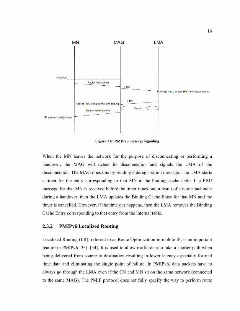
Figure 2.6: PMIPv6 message signaling
When the MN leaves the network for the purpose of disconnecting or performing a
handover, the MAG will detect its disconnection and signals the LMA of the
disconnection. The MAG does this by sending a deregistration message. The LMA starts
a timer for the entry corresponding to that MN in the binding cache table. If a PBU
message for that MN is received before the timer times out, a result of a new attachment
during a handover, then the LMA updates the Binding Cache Entry for that MN and the
timer is cancelled. However, if the time out happens, then the LMA removes the Binding
Cache Entry corresponding to that entry from the internal table.
2.5.2 PMIPv6 Localized Routing
Localized Routing (LR), referred to as Route Optimization in mobile IP, is an important
feature in PMIPv6 [33], [34]. It is used to allow traffic data to take a shorter path when
being delivered from source to destination resulting in lower latency especially for real
time data and eliminating the single point of failure. In PMIPv6, data packets have to
always go through the LMA even if the CN and MN sit on the same network (connected
to the same MAG). The PMIP protocol does not fully specify the way to perform route

17
optimization but it indicates that there is a flag called EnableMAGLocalRouting that can
be set on a common MAG that has a CN and MN connected to. If there is a constant
traffic going on between MN and CN, then by setting this flag, MAG will just route
packets directly between CN and MN without the need to go through the LMA. However,
there are other cases that need to be considered as specified in PMIP localized routing
problem statement [5]. A brief description of the cases is outlined below where each case
is referred to by the following notation: A[number of MAGs][number of LMAs]:
A11: In this case, there is one MAG and one LMA. The MN and the CN are both
connected to the same MAG and it needs to forward the packets between MN and
CN directly without forwarding any one to the LMA.
A12: In this case, there is one MAG and two LMAs that have MN and CN
registered with. The common MAG has to forward packets directly between CN
and MN and both LMAs have to accommodate this localized routing by
considering their policy.
A21: This is a very common case where there are two MAGs that are registered
with the same LMA. In this case, the MAGs forward packets to each other and
respectively forward the packets to their destination without having to go through
the common LMA.
A22: This is the most complicated case in which there are two MAGs and two
LMAs. Each one of the MN and CN is registered with a different MAG and
different LMA. The MN and CN have their data delivered using MAGs only
without involving the LMA in forwarding the data packets. However, they will
need to be involved in the setup of the localized routing path. Maintenance of the
localized routing states and avoiding race conditions is one of the issues facing
such feature.

18
In an attempt to establish a localized routing algorithm to handle the above situation in
PMIPv6, multiple PMIPv6 localized routing proposals have been made in which they
vary in efficiency, signaling, and latency.
2.5.2.1 PMIPv6 Localized Routing Proposal 1
The proposal attempts to approach all of the above scenarios individually as described
below [19]:
• Scenario A11:
The LMA has to detect that there is a traffic flow between MN1 and CN (or MN2
for ease of reference) that are attached to the same MAG. The detection algorithm
is not specified and is left up to the application. Once potential localized routing
path is detected, the LMA sends a Localized Routing Initiation (LRI) message to
the MAG involved. This is a mobility header message and it has the MN identifier
and the prefix(es) of both MNs. As a result, the MAG sends a Localized Routing
Acknowledgement (LRA) message back to the LMA and starts forwarding the
packets between the MNs. If the MAG is not configured to participate in the
localized routing, then it sends an LRA message with a status code to indicate the
status and every entity reverts back to its normal procedure. The LMA can still
cancel the localized routing by sending an LRI and requesting to cancel. If a
handover happens, the LMA will need to re-establish the localized routing
depending on which of the cases it falls under.
• Scenario A21:
This scenario is similar to the above scenario in terms of handling. The LMA
detects that there is a flow between the MNs that are attached to different MAGs.
As a result, it sends an LRI message to each of the MAGs with the IP address of
the counterpart MAG in addition to the MN-ID and the prefixes. The MAGs
replies with LRI messages confirming the status of the localized routing. Upon

19
success, a tunnel is established between the MAGs and the packets are forwarded
directly between them. Again, if a handover for MN1 happens to a New MAG
(NMAG), then LMA can detect that from the PBU message and has to establish
the localized routing again with the NMAG and inform the other MAG of the
change.
• Scenario A12:
In this scenario, there is one MAG and two LMAs. As a result, there is no way for
the LMA to know that there is a traffic going between MN1 and MN2. Therefore,
the localized routing initiation has to come from the MAG. The MAG sends LRI
message to each of the LMA indicating the MN-ID, prefixes, and address of the
counterpart LMA. The LMA has to respond with an LRA message to confirm the
support for localized routing for the MN. Once the MAG receives the LRA from
both LMAs with a status code indicating success, then it can start the localized
routing between the MNs. An example of the messages exchanged is shown in
Figure 2.7. If a handover happens, then the localized routing has to re-establish
again from the beginning in the same way the localized routing is established in
scenario A22.

20
Figure 2.7: Example of localized routing establishment in scenario A12 [19]
• Scenario A22:
This scenario has not been discussed in the draft yet and is left up for future
versions.
2.5.2.2 PMIPv6 Localized Routing Proposal 2
Another proposal to handle the localized routing is presented in [20], [21]. The main
drive for such proposal is the LMA. This protocol introduces the idea of Route
Optimization Controller which sits on all of the LMAs. However, in the case of having
multiple LMAs involved in the scenario, only one LMA takes over so that the states of
the PMIPv6 entities are maintained by a single LMA and race condition is avoided.
In a complicated topology where there are multiple LMAs, an LMA can detect the
possibility of localized routing by inspecting the source and destination addresses of the
data packets traversing through it. As a result, it acts as a route optimization trigger while

21
the peer LMA acts as the Route Optimization Controller that setups and maintains the
localized routing. In addition, address resolution of the other LMA is required using
other means of resolution in order to setup the localized routing. In the case where there
is a single LMA, the same LMA can be the Route Optimization trigger and Route
Optimization Controller at the same time. There are two modes for this protocol, proxy
mode in which the messages between the MAGs are relayed through the LMAs while in
the direct mode, the MAGs can communicate directly and exchange messages. The latter
case may require some security setup between the MAGs but is simpler when it comes to
communication. This is why the latter case is chosen for consideration. The main two
scenarios considered are as follows:
• Single LMA:
In the case where there is one LMA and two MAGs (along with their respective MNs)
attached to it, the LMA acts as a trigger and Route Optimization Controller at the same
time. The LMA detects a possibility of establishing a localized routing from the traffic
flow and triggers itself to start route optimization. It sends an RI Init message to one of
the MAGs informing it of the possibility of having an Route Optimization. This message
contains the information of the other MAG. MAG2 sends an Route Optimization Setup
message to MAG1 which in turns sends an Route Optimization Setup Ack message to
MAG2 indicating that Route Optimization can be performed. MAG2 sends an Route
Optimization Init Ack to the LMA indicating the success of the Route Optimization
request. If any failure happens, then Route Optimization Init Ack will indicate that in the
status code. The above messaging is illustrated in Figure 2.8.

22
Figure 2.8: Route Optimization setup in the case of a single LMA [20]
If a handover is performed by MN from MAG2 to NMAG, then LMA will receive a PBU
message indicating the attachment of the MN to NMAG. As a result, the LMA will be
aware of the handover and of the fact that MN is a participant of the route optimization.
Therefore, the LMA re-establish the route optimization with the NMAG by sending
MAG1 a Route Optimization Init of its information. The messaging between MAG1 and
NMAG will take place like before and the new route optimization is completed. The
entries in the previous MAG (MAG2) will be left to expire so MAG2 can take care of
cleaning them up.
• Multiple LMAs:
In the case of having multiple LMAs, the trigger LMA detects that there is a traffic flow
between the MNs and that there is a possibility of setting up localized routing. As a
result, one of the LMA sends Route Optimization trigger to the peer LMA that has the
Route Optimization Controller functionality (after resolving the address of the LMA by

23
other means). As soon as the Route Optimization Controller LMA receives the trigger, it
sends the Route Optimization Init to one of the MAGs and the setting up of the route
optimization continues as described before in the case of a single LMA.
If handover is performed by a MN, then the LMA will detect the handover by receiving
the PBU message. Depending on which LMA detects the handover, it can either trigger
the other LMA or just perform the Route Optimization Controller functionality. The steps
to setup new route optimization are similar to the ones described previously in the
handover when we have a single LMA scenario.
It should be noted that the MAGs need to keep refreshing the LMA of the states of
localized routing before the LMA Route Optimization timer expires by sending Route
Optimization refresh messages. In addition, the MAG can request the localized routing
before the LMA enforces it by sending a Route Optimization Request message. This is a
deployment-dependent procedure.
One problem with the above proposal is the amount of signaling involved in addition to
the loss of packets when handover is performed. The previous MAG will keep receiving
the packet and there is no way of recovering these packets during the handover.
2.5.3 PMIPv6 Handover
PMIPv6 handover is one of the hot issues for research as it results in a significant amount
of latency and packets loss. When MN performs a handover from one MAG to another,
then the interface setup needs to take place by getting assigned a new prefix and
performing optionally the DAD algorithm [39]. This is on top of having MN being
authorized again [35]. As a result, multiple IETF drafts were written to improve the
efficiency of the handover. Some of the relevant and successful proposals are discussed
below.

24
2.5.3.1 Fast Handover for Proxy MIPv6
Fast Handover for Proxy MIPv6 (F-PMIPv6), introduced in RFC 5949, performs an
efficient handover by reducing the delay and minimizing packet loss without involving
the MN in signaling to comply with the main goal of PMIPv6 [2], [22]. This protocol is
based on establishing a bidirectional tunnel between the Previous MAG (PMAG) that the
MN is handing over from and the NMAG that the MN is handing over to and performing
context transfer between them as described later [40]. Access Network is composed of
Access Point as defined in [RFC 5568] and these are often referred to as base station in
cellular networks. Each MAG has an AP therefore AP and MAG are often combine as
one entity.
There are two modes of operation for F-PMIPv6: the predictive mode and the reactive
mode. In the predictive mode, the bidirectional tunnel between the NMAG and PMAG is
established prior to performing a handover. While in the reactive mode, it is established
after the MN starts its handover process. In the most severe case when the MN is
detached from both old link and new link, the MAGs have to have the capability of
buffering the packets for future forwarding. For the predictive mode to work efficiently
and to avoid the involvement of MN in the IP mobility signaling, it is required that the
MN reports a lower layer information to the Access Network, which in turns, reports this
information at short timing to the PMAG.
• Predictive Mode:
Figure 2.9 below shows the message sequencing that happens in the predictive mode. In
this mode, the MN detects that it is about to perform a handover. Therefore, it reports
some low layer information to the Previous Access Network such as the MN-ID and the
new AP identifier to which the MN will move. In some cases, the Previous Access
Network can map the AP identifier to the New Access Network but this is an access
technology specific.

25
New Access Network sends a message to the PMAG informing it of the MN intention of
performing a handover along with the MN-ID and the new AP identifier. The PMAG
derives the NMAG information from the N-AP identifier and sends a Handover Initiate
(HI) message to the NMAG with the Proxy flag (P) set and other relevant information
that are related to this protocol. The NMAG sends a Handover Initiate Acknowledgment
(HACK) to the PMAG with the P flag set. As a result, a bidirectional tunnel is established
between the PMAG and the NMAG. Any packet that is destined to the MN and received
by the PMAG can be forwarded over the tunnel to the NMAG and buffered till the MN is
fully attached and handover is completed. When the handover is completed on the
network side, the MN is triggered to perform handover to the new access network. Any
packets that are sent from the MN are sent to the NMAG and forwarded to the PMAG
before it is sent to the LMA. Once the MN completes the PMIPv6 normal handover
procedure (PBU and PBA), the data packets will go through NMAG only and the tunnel
is no longer needed.

26
Figure 2.9: Predictive Fast Handover for PMIPv6 [2]
• Reactive Mode:
In the case of the reactive mode, the tunnel establishment has to come from the NMAG
as the AP information is acquired only when the MN moves to the new link. The
information can be provided to the NMAG either from the MN on the old link or by a

27
means of communication between the Previous Access Network and the New Access
Network. Once this information is acquired, similar procedure to the predictive mode is
followed. Figure 2.10 shows this for clarification purposes.
Figure 2.10: Reactive Fast Handover for PMIPv6 [2]

28
2.5.3.2 Transient Binding for Proxy MIPv6
This draft attempts to enhance the handover performance by minimizing packet loss and
packet forwarding delay that can occur during handover [22], [3]. This mainly focuses on
devices with multiple interfaces when a device registers with a new MAG and the LMA
deregisters the previous MAG. The new interface takes some time to setup and all the
packets sent on the old link will be dropped at the LMA since there is no Binding Cache
Entry for that MN with that PMAG. This draft also adds an enhancement on the handover
performance for single interface MN. Figure 2.11 below describes the general approach
for Transient PMIPv6 for an MN performing a handover.
Figure 2.11: Transient Binding for PMIPv6 [22]
When MN attaches to the NMAG, the NMAG sends a PBU packet with the transient
option in it. In that case, the LMA adds the NMAG as another forwarding path to the

29
Binding Cache Entry for that MN and marks it as transient. Alternatively, the LMA can
initiate the transient procedure by telling the NMAG in the PBA message that there is a
transient entry for that MN. The NMAG has to update its BUL list with the transient case.
In the transient state, the LMA accepts uplink packets from both the PMAG and NMAG.
In addition, downlink can still be forwarded to the PMAG to make use of the old link.
This is denoted as “late path switch”. In the case where there is a single interface
handover, the PMAG has to get the packets to the MN by sending them to the Previous
Access network then New Access Network then MN. The transient option can be turned
off by setting the Binding Cache Entry to an active state. This can be done by a transient
time out at the LMA, the receiving of an empty PBU when the handover is completed, or
a deregistration message from the PMAG.
2.5.4 Concluding Remarks
As can be seen in this chapter, a lot of research has been done in the area of IP mobility
management where the main goal is to maintain connectivity of MN while it is roaming
around between different access networks. However, each one of the protocols/solutions
has some drawbacks that another protocol aims to fix and a lot of analytical research has
been done such as [21, 22, 23-25]. For example, MIPv6 provided the base model for
maintain IP connectivity but it suffers from long handover delays, increased signaling,
and packet loss. HMIPv6 and FMIPv6 were introduced to reduce handover delay level;
however all of these protocols require software modification on MN which makes it hard
for operators to deploy them on top of MN involvement of the handover operation.
PMIPv6 was introduced to minimize the above issues and mainly isolate the MN from
participating in the handover signaling. Despite that, handover delay, packet loss, and the
non-optimal paths for data packets were areas that needed improvement. This prompted
the development of F-PMIPv6 and Transient Binding for PMIPv6 in order to reduce
handover delay and packet loss. Localized routing proposals were introduced to fix the
issue of having non-optimal path for data packets. However, when the handover delay
and packet loss are combined with localized routing, then it becomes a new issue by itself

30
that has not been solved or optimized yet. Precisely, the issue is more critical when
performing a handover while LR session is in place as there is no integration. This will
cause handover and LR to re-establish independently and add consequently extra cost
such as LR handover establishment delay, increased signaling and core network element
excess utilization. The next chapter will look at the proposed solution to fix them.

31
Chapter 3
O-PMIPv6: Optimized Proxy Mobile IPv6
In this chapter, the proposed O-PMIPv6 protocol is described. Section 3.1 introduces a
general overview of how O-PMIPv6 works and what it intends to achieve. Section 3.2
presents a detailed description of the O-PMIPv6 design and operation.
3.1 Overview of the O-PMIPv6
As mentioned before, the main idea of O-PMIPv6 is to have the LR session restored
between MN and its CN while MN is performing handover from one MAG to another in
the same PMIPv6 domain. This is based on the assumption that LR was established
between MN and CN prior to MN handover. O-PMIPv6 is based on the implementation
of F-PMIPv6 in order to utilize the advantages of F-PMIPv6 over PMIPv6 such as
reduced handover delay and minimized packet loss. The idea behind this solution is to
make the F-PMIPv6 signaling participate in the route optimization establishment the
moment that the MN handover is triggered by the network. Using this solution, the MN
will be able to handover while maintaining its LR. In other words, there is no need to re-
establish a new LR session after the handover is complete.
The basic idea is to transmit the LRI/LRA information using the HI/HACK messages that
F-PMIPv6 uses to perform the MN handover. By doing that, we keep the same benefits
that F-PMIPv6 introduces to the basic PMIPv6 while giving the NMAG that MN is
handing over to the capability of restoring MN’s LR session at the same time.
When the LR session is restored, then all of the MN data packets are sent directly from
NMAG to CMAG where the CN is attached to. As discussed before, in the case of
PMIPv6, data packets are buffered at the NMAG (or lost if buffering is limited or
disabled), then sent to LMA and finally forwarded to CMAG until LR is established. In

32
the case of F-PMIPv6, the data packets are sent from NMAG to PMAG then to LMA and
forwarded to CMAG as soon as MN is attached to NMAG. This is done until LR is
established. However, in the case of O-PMIPv6, data packets are sent directly from
NMAG to CMAG as soon as the MN is attached to the NMAG. This will result in the
reduction in the number of packets going on the non-optimal path and, consequently, will
result in a less packet delivery delay on top of reduced utilization of core network
elements such as LMA. It should be noted that combining the handover of MN and LR
session using O-PMIPv6 will have less signaling cost reduced total handover delay of
both MN and LR session as proved in the following chapters.
3.2 Design of O-PMIPv6
In section, we are going to discuss the implementation details of O-PMIPv6. The section
starts with stating the details of the protocol operation in both the predictive and reactive
modes. Then, the format of the signaling messages used in this protocol will be shown
along with the description of each field. The signaling messages discussed in this section
are the O-PMIPv6 version of HI and HACK messages in addition to the LR Request
mobility option.
3.2.1 Protocol Operation
Prior to the operation of O-PMIPv6, we assume that MN has an already established LR
with its CN. When PMAG detects that the handover of MN is imminent due to degrading
signal strength, it sends HI packet to the NMAG that MN is about to handover to. This
can happen in reactive or predictive mode as explained by F-PMIPv6 which is outside the
scope of this thesis.
In case of the predictive mode, PMAG includes in the HI message the information
required to give the NMAG the capability to establish LR for MN, in a similar fashion to
LRI packet. Basically, NMAG will be able to know MN information (such as prefix
and/or ID), CN information (prefix and/or ID), and the address of the remote CMAG.
When NMAG receives this information, then it will setup forwarding mechanism so that

33
all the data packets arriving from MN upon its new attachment and destined to the same
CN are forwarded to CMAG. NMAG will reply to the PMAG with HACK message as
described by the F-PMIPv6 and indicating success of the operation.
In case of the reactive mode, NMAG sends HI message to PMAG with a request mobility
option for LR information for the attached MN. PMAG receives the HI message and
replies back with HACK message that includes the requested LR information (such as
prefix and/or ID), CN information (prefix and/or ID) and the address of the remote
CMAG. When NMAG receives this information, then it will setup forwarding
mechanism so that all the data packets arriving from MN and destined to the same CN are
forwarded to CMAG.
If CMAG happens to be different than PMAG, then NMAG will send an LRI message to
CMAG to enable it to update its LR table. The effect of the different topologies and how
NMAG knows which packets to send along with the proposed control packet headers are
explained in the sections below. It should be noted that this is based on the assumption
that there is already a security association between the MAGs in communication, and
how to maintain a highly secured network is outside the scope of this research.
The only two messages that are modified from F-PMIPv6 protocol are Handover Initiate
(HI) and Handover Acknowledgment (HACK).
3.2.2 Handover Initiate (HI) Message Format
O-PMIPv6 uses the HI message to prepare the NMAG for the MN that will be attaching
to it in the case of predictive mode by providing the MN ID, MN prefix and its LR
session information. In the case of the reactive mode, the HI message is used to request
more information from PMAG such as MN prefix and LR information. Figure 3.1 shows
the modified the version of the original HI message. The fields that are newly introduced
or have their possible values modified are indicated with the bold color and explained
below.

34
Figure 3.1: Handover Initiate message format
Below is the description of the message fields:
'S' flag: Assigned Address Configuration [RFC5949]. Unused in O-PMIPv6.
'U' flag: Buffer flag [RFC5949]. Unused in O-PMIPv6.
'P' flag: Proxy flag [RFC5949]. Unused in O-PMIPv6.
'F' flag: Forwarding flag [RFC5949]. Unused in O-PMIPv6.
'O' flag: O-PMIPv6 flag (new field). Used to distinguish the HI message from
F-PMIPv6 defined in [RFC5949]. It should be set to 1 to indicate that this
packet is O-PMIPv6 and carries LR information. Otherwise, it becomes an F-
PMIPv6 message
'R' flag: LRI flag (new field). It is set to 1 to indicate it contains relevant LRI
information. Otherwise, no LRI information is appended in this message.
Reserved: Set to 0 as defined in [RFC5949]. Unused in O-PMIPv6.
Code: Status code [RFC5949]. Unused in O-PMIPv6.

35
Lifetime: LR supported lifetime (new field). The requested time in seconds for
which the sender wishes to have local forwarding. It is usually set to the
remaining lifetime for the LR session from the sending MAG perspective. A
value of 0xffff (all ones) indicates an infinite lifetime.
Sequence #: Packet sequence number [RFC5949]. It includes the sequence
number of this message so replies to this message can be matched.
Mobility Options: This field contains one or more mobility options, whose
encoding and formats are defined in [RFC3775]. A new combination of
options are added in O-PMIPv6 as discussed below:
The following options can be added in case of the predictive mode:
o Mobile Node Identifier (MN1-ID) whose format is defined in
[RFC3775]. This is already required by F-PMIPv6 [RFC5949] to
identify the target node and should be used by O-PMIPv6.
o Mobile Node Home Prefix (MN1-HNP) whose format is defined in
[RFC3775].
o Mobile Node Identifier (MN2-ID) whose format is defined in
[RFC3775]. This identifies the other mobile node involved in the LR,
i.e MN2 or CN.
o Mobile Node Home Prefix (MN2-HNP) whose format is defined in
[RFC3775]. This is the prefix for MN2 or CN.
o Remote MAG IPv6 (Remote Previous Care-of-Address) as defined by
the [19]. This is to identify the CMAG that MN2/CN is attached to.
This is optional as it is implementation specific but it is recommended.
The following options can be added in case of the reactive mode:

36
o Mobile Node Identifier (MN1-ID) whose format is defined in
[RFC3775]. This is already required by F-PMIPv6 [RFC5949] to
identify the target node and should be used by O-PMIPv6.
o Context Request option for Mobile Node Home Prefix (MN1-HNP)
whose format is defined in [RFC 5213].
o Localized Routing Request option as defined section 3.2.4.
It should be noted that adding the Remote MAG IPv6 option can be redundant if the
receiving MAG is smart enough to determine where the CN is attached to. For example,
if this option does not exist, then it means that CN is either attached to the receiving
MAG or to the sending MAG. The receiving MAG can determine through its internal
tables which one of the cases applies. Accordingly, it can set the Remote MAG IPv6 to
be either itself (if CN is attached to it) or to the source IP Address of the HI message (if
CN is attached to the sending MAG). This is up to the operator to determine the exact
operation and expectation if its network MAGs.
The advantage of this message format is that if the receiving MAG happens to be
incompatible with O-PMIPv6 format, then this control packet can still be used as
[RFC5568] and the operation of the receiving MAG as [RFC5568] dictates.
3.2.3 Handover Acknowledgement (HACK) Message Format
O-PMIPv6 uses the HACK message to acknowledge the receipt of the HI message by the
NMAG and provide status information in case of the predictive mode. In the case of the
reactive mode, it is used by the PMAG to provide the requested information to the
NMAG. Figure 3.2 shows the modified version of the original HACK message. The
fields that are newly introduced or have their possible values modified are indicated with
the bold color and explained below.

37
Figure 3.2: Handover Acknowledgment message format
Below is the description of the message fields:
'U' flag: Same as defined in the HI message description above.
'P' flag: Same as defined in the HI message description above.
'F' flag: Same as defined in the HI message description above.
'O' flag: O-PMIPv6 flag (new field). Used to distinguish the HI message from
F-PMIPv6 defined in [RFC5949]. It should be set to 1 to indicate that this
packet is O-PMIPv6 and carries LR information. Otherwise, it becomes an F-
PMIPv6 message
'R' flag: LRI flag (new field). It is set to 1 to indicate it contains relevant LRI
information. Otherwise, no LRI information is appended in this message.
Reserved: Same as defined in the HI message description above.
Code: Status code. In addition to what is defined in [RFC5949], the following
codes are used for LR purposes (which is different from [19] to avoid conflict
with the [RFC5949] codes):

38
1: Success
2: Localized Routing Not Allowed
Lifetime: LR supported lifetime (new field). This is lifetime of the LR session
that is supported and it is usually copied from the HACK message.
Sequence #: Same as defined in the HI message description above.
Mobility Options: This field contains one or more mobility options, whose
encoding and formats are defined in [RFC3775]. A new combination of
options are added in O-PMIPv6 as discussed below:
In case of predictive mode, the encoding is defined in [RFC5949], in
addition to what was presented in the HI mobility options. Basically, in the
same options that were presented in the HI message in the case predictive
mode should exist in this message.
In case of reactive mode, then all of the requested context and LR options
should be presented.
3.2.4 Localized Routing Request Option Message Format
This mobility option is used by the HI message in the case of the reactive mode to request
LR information for the MN that has just attached to the NMAG. Figure 3.3 shows the
Localized Routing Request mobility option header. This option header is a general
mobility option type that is defined in [RFC 3775] in which depending on the values used
will indicate what mobility option it is as each option has a different purpose. Using the
values below indicates that this mobility option is Localized Routing Request mobility
option.

39
Figure 3.3: Handover Acknowledgment message format
Below is the description of the message fields:
Option Type: Set to 46. This is a new value introduced in the O-PMIPv6 as it
is the next available number and it indicates this specific mobility option type.
Option Length: Set to 0 since there is no further data needed
Reserved: This field is unused and must be set to 0 by the sender and ignored
by the receiver.
3.3 O-PMIPv6 Operation in Various Network Topologies
The proposed protocol, O-PMIPv6, work successfully in any single LMA PMIPv6
domain no matter how the topology is. However, depending on where the CN is, the
MAGs can be smart enough to determine what to put in the HI/HACK message for
maximum efficiency. There are generally three possible topologies in which the MN, CN
and the MAG can have different combinations:
• Topology 1: MN is connected MAG1 and CN is connected to MAG2 but MN
performs a handover to MAG3.
• Topology 2: MN is connected to MAG1 and performs a handover to MAG2
where CN is connected to.
• Topology 3: MN and CN are connected to MAG1 but MN is moving to MAG2.

40
Each one of these different topologies is discussed in the following subsections for
clarity. Using the predictive mode or the reactive mode will yield the same benefits for
O-PMIPv6 as compared to F-PMIPv6 and PMIPv6. It should be noted that only the
predictive mode is considered here for simplicity and protocol illustration, however the
same theory can be applied for reactive mode. Detailed analysis of the reactive mode is
left out as a future work. In addition, smart MAGs are considered which means that they
have the capability of determining the remote MAG that the CN is attached to in case of
topology 2 and 3 as explained in the next subsections. This is to show the maximum
advantage of this protocol with minimum change to the original F-PMIPv6.
3.3.1 Topology One
The first topology that may be possible is shown in Figure 3.4. MN is attached to MAG1
and CN is attached MAG2. MN is willing to perform a handover to MAG3 as it is
moving toward MAG3. Therefore, MAG1, MAG2, and MAG3 can be referred to as
PMAG, CMAG and NMAG respectively. All of these MAGs are attached to the same
LMA in a single LMA domain. There is already a localized routing path established
between MN and CN in which the optimal path is between PMAG and CMAG. Once
MN is attached to the NMAG, the new localized routing optimal path is to be established
between NMAG and CMAG.
Figure 3.4: Handover scenario for topology 1

41
The messages exchange of O-PMIPv6 for performing handover and re-establishment of
the LR path between CN and MN is shown in Figure 3.5. When the link between the MN
and PMAG starts to go down due to degraded signal strength, PMAG sends a HI message
to NMAG informing it of MN handover. PMAG includes the LR information in the HI
message such CN ID, CN prefix and the CMAG address. When NMAG receives the HI
message, it firstly processes it according to the F-PMIPv6 specification (such as tunnel
establishment with PMAG for all MN data packets). Then, it checks for the O-PMIPv6
flag and if it is set, it processes the HI packet as O-PMIPv6 by creating an entry in its
internal LR table for MN with CMAG being the remote MAG of the data packets that are
destined to CN. NMAG sends back HACK message to PMAG to indicate the success of
the operation. In addition, it will exchange the LRI/LRA information with CMAG to
update the CN LR info in CMAG of NMAG being its peer LR node instead of PMAG.
The LRI/LRA communication of the [19] is used. Therefore, the new LR is established.
When MN is attached to NMAG, the NMAG sends the prefix information right away to
it. NMAG and LMA exchange the PBU/PBA messages as in PMIPv6. When MN sends a
data packet to CN on the new link, even before PBU/PBA is exchanged, then the packet
will go on the optimal path from NMAG to CMAG.

42
Figure 3.5: Call flow for O-PMIPv6 in topology 1
3.3.2 Topology Two
The second topology that may be possible is shown in Figure 3.6. MN is attached to
MAG1 and CN is attached MAG2. MN is willing to perform a handover to MAG2 as it is
moving toward MAG2. Therefore, MAG1 can be referred to as PMAG while MAG2 can
be referred to as NMAG (from MN perspective) or CMAG (from CN perspective). Both
MAGs are attached to the same LMA in a single LMA domain. There is already a
localized routing path established between MN and CN in which the optimal path is
between PMAG and CMAG. Once MN is attached to the NMAG, the new localized
routing optimal path is to be established locally at NMAG (or CMAG).

43
Figure 3.6: Handover scenario for topology 2
The messages exchange of O-PMIPv6 for performing handover and re-establishment of
the LR path between CN and MN is shown in Figure 3.7. When the link between the MN
and PMAG starts to go down due to degraded signal strength, PMAG sends a HI message
to NMAG informing it of MN handover. PMAG includes the LR information in the HI
message such CN ID and CN prefix. It does not include the CMAG address in the HI
message as the CMAG is NMAG in this topology. When NMAG receives the HI
message, it firstly processes it according to the F-PMIPv6 specification (such as tunnel
establishment with PMAG for all MN data packets). Then, it checks for the O-PMIPv6
flag and if it is set, it processes the HI packet as O-PMIPv6 by creating an entry in its
internal LR table for MN with itself being the remote MAG of the data packets that are
destined to CN. Also, it will update the LR entry of CN as well. Therefore, NMAG will
just do local forwarding of packets between MN and CN. After that, NMAG sends back
HACK message to PMAG to indicate the success of the operation. When MN is attached
to NMAG, the NMAG sends the prefix information right away to it. NMAG and LMA
exchange the PBU/PBA messages as in PMIPv6. When MN sends a data packet to CN on

44
the new link, even before PBU/PBA is exchanged, then the packet will be forwarded
locally to CN.
Figure 3.7: Call flow for O-PMIPv6 in topology 2
3.3.3 Topology Three
The third topology that may be possible is shown in Figure 3.8. Both MN and CN are
attached to MAG1. MN is willing to perform a handover to MAG2 as it is moving toward
MAG2. Therefore, MAG1 can be referred to as PMAG (from MN perspective) or CMAG
(from CN perspective) while MAG2 can be referred to as NMAG. Both MAGs are
attached to the same LMA in a single LMA domain. There is already a localized routing
path established between MN and CN in which data packets are forwarded locally
between them at PMAG (or CMAG). Once MN is attached to the NMAG, the new

45
localized routing optimal path is to be established between NMAG and PMAG (or
CMAG).
Figure 3.8: Handover scenario for topology 3
The messages exchange of O-PMIPv6 for performing handover and re-establishment of
the LR path between CN and MN is shown in Figure 3.9. When the link between the MN
and PMAG starts to go down due to degraded signal strength, PMAG sends a HI message
to NMAG informing it of MN handover. PMAG includes the LR information in the HI
message such CN ID and CN prefix. It does not include the CMAG address in the HI
message as the CMAG is PMAG in this topology and NMAG knows that CN is not
attached to it and must be attached to PMAG. When NMAG receives the HI message, it
firstly processes it according to the F-PMIPv6 specification (such as tunnel establishment
with PMAG for all MN data packets). Then, it checks for the O-PMIPv6 flag and if it is
set, it processes HI packet as O-PMIPv6 by creating an entry in its internal LR table for
MN with PMAG being the remote MAG of the data packets that are destined to CN.
After that, NMAG sends back HACK message to PMAG to indicate the success of the

46
operation. PMAG also update the LR information of its CN in its internal tables. When
MN is attached to NMAG, the NMAG sends the prefix information right away to it.
NMAG and LMA exchange the PBU/PBA messages as in PMIPv6. When MN sends a
data packet to CN on the new link, even before PBU/PBA is exchanged, then the packet
will go on the optimal path from NMAG to PMAG (which happens to be the CMAG in
this topology).
Figure 3.9: Call flow for O-PMIPv6 in topology 3
In conclusion, it can be seen from the above three topologies that O-PMIPv6 can work
with any combination of MAGs, MN and CN in a single-LMA domain and the LR
session will resume upon MN attachment to the NMAG as expected. Also, it is worth
mentioning that new modifications to the signaling messages do not make the operation
of MAG fail in case it does not support O-PMIPv6 as the modifications to the HI and
HACK messages can be ignored. Therefore the messages can be treated as F-PMIPv6
message and the handover will continue as specified in the F-PMIPv6 protocol.

47
Chapter 4
Mathematical Analysis
In order to evaluate the effectiveness of the proposed O-PMIPv6 solution, it is necessary
to perform a theoretical analysis on the common performance parameters for any
mobility management protocols. The parameters that are chosen for this analysis are LR
establishment latency, signaling cost, and network utilization. We compare O-PMIPv6
with F-PMIPv6 and PMIPv6 since these are the most widely accepted NETLMM
protocols as evident by them being in an RFC state. Also, these protocols were
specifically chosen because O-PMIPv6 is based on F-PMIPv6 which was introduced to
specifically reduce the handover delay and packet loss in the basic PMIPv6 domain. The
comparison is done when MN performs handover assuming that LR is enabled and there
is already an optimized path established prior to performing the handover.
In this chapter, we first propose a theoretical network model including its assumptions.
Then, we study the different scenarios of intra-domain handover of MN that can happen
when a single LMA exists and the rest of the MAGs are attached to it. These scenarios
are studied and compared with the above selected mobility management protocols. Next,
we also perform a detailed theoretical analysis on the different performance parameters
for the chosen mobility management protocols. Finally, we present the conclusion of our
theoretical analysis.
4.1 Network Model
In order to analyze the performance of the mobility protocols, we propose a single-LMA
PMIPv6 domain with a hexagonal model in which the network consists of N cells. Each
cell is covered by a MAG and one or more Access Point(s). We assume that the signal
strength is strong enough such that there is some overlap coverage at the edges of each

48
cell, meaning that any MN at any location will always have a signal. MAGs and LMA are
connected through a number of hops. This model is depicted in Figure 4.1. For the
purpose of this chapter analysis, we assume that CN and MN are initially connected to
MAG1 and MN is performing a handover to MAG2. DMAG-LMA denotes the number of
hops between LMA and MAG. The average number of hops between two MAGs is
referred to by DMAGs. It is typically assumed that the average number of hops between
two MAGs is less than the number of hops between LMA and MAG [8]. Due to the
nature of the hexagonal network, the number of hops between two MAGs, is equal to √N
[9], [21], [31]. An MN is connected to MAG through an Access Point. It is assumed that
all the links between the major entities (MAG, LMA, and Access Point) are wired links
while the link between MN and Access Point is wireless.
Figure 4.1: Single LMA PMIPv6 domain for the mathematical analysis

49
For the purpose of this model, the notations and their descriptions are shown in Table 4.1.
Table 4.1: System notations and their descriptions
System notation Description
TMN-AP
Transmission delay between the MN and Access Point
TAP-MAG
Transmission delay between Access Point and MAG
TMAG-LMA
Transmission delay between MAG and LMA
TMAGs
Transmission delay between any two MAGs
TMN-MAG
Transmission delay between the MN and MAG
TData Transmission delay of the data packet from source to destination
Lw
/ Lwl
Wired/wireless link delay
Bw
/ Bwl
Bandwidth of wired/wireless link
Wx Average waiting time at node X
DX-Y
The Number of hops between nodes X and Y
PSx Packet size of packet that of type X
L Session length
λserver Arrival rate at any server (# of packets/second)
λhost Send/receive rate at the host (# of packets/second)
Q Probability of wireless link failure
Dwl Number of wireless links in a connection path
To facilitate the behaviour of the model, the following assumptions are made:
• Address configuration is only performed using stateless address
autoconfiguration, and the time required to combine the network prefix from the
Router Advertisement message to its interface address is negligible.

50
• There is constant rate traffic between MN and CN. Prior to performing a
handover, we assume that an optimal path has been established between MN and
CN using LR procedure and all the packets are going through this optimized path.
• The MN starts attaching its interface to the new Access Point as soon as its
previous communication signal strength is weakening. Therefore, we assume that
the latency until the Access Point knows about MN attachment is referred to as L2
handover latency.
• For simplicity, Router Solicitation message is not considered here. Thus, only
Router Advertisement message can affect the movement detection of the MN.
• LR is considered completed and packets are optimized when LRA is received
(acknowledgement).
• Access Point is considered as a normal hop.
• The processing latency of L2 event at NMAG is ignored for simplicity.
• Each hop/router/entity is modeled as an M/M/1 server with mean service time (u)
equal to processing cost of the server and equal arrival rate of ג (server). The system
follows a Poisson Process.
• Waiting time of a packet in a system (server) is defined as queuing delay + service
time.
• The link delay in both direction of any link is symmetric, i.e. T(X,Y) = T(Y,X)
• It is assumed the MN is the sending node of the traffic and CN is the receiving
node of the traffic for this exercise.
For a system that follows a Poisson Process, the expected total waiting time (W) for a
packet in a system (queuing + service) is [26]:
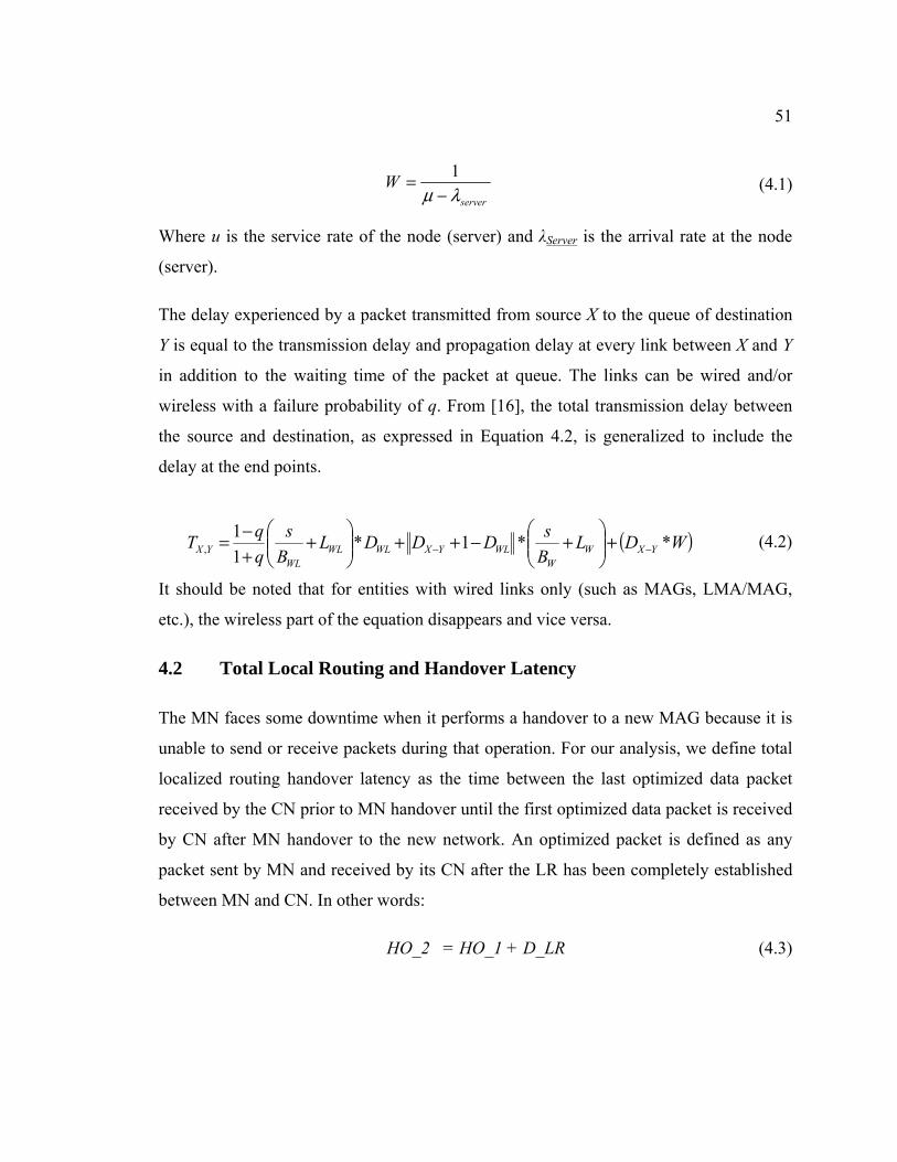
51
Where u is the service rate of the node (server) and λServer is the arrival rate at the node
(server).
The delay experienced by a packet transmitted from source X to the queue of destination
Y is equal to the transmission delay and propagation delay at every link between X and Y
in addition to the waiting time of the packet at queue. The links can be wired and/or
wireless with a failure probability of q. From [16], the total transmission delay between
the source and destination, as expressed in Equation 4.2, is generalized to include the
delay at the end points.
(4.2)
It should be noted that for entities with wired links only (such as MAGs, LMA/MAG,
etc.), the wireless part of the equation disappears and vice versa.
4.2 Total Local Routing and Handover Latency
The MN faces some downtime when it performs a handover to a new MAG because it is
unable to send or receive packets during that operation. For our analysis, we define total
localized routing handover latency as the time between the last optimized data packet
received by the CN prior to MN handover until the first optimized data packet is received
by CN after MN handover to the new network. An optimized packet is defined as any
packet sent by MN and received by its CN after the LR has been completely established
between MN and CN. In other words:
HO_2 = HO_1 + D_LR (4.3)
server
Wλμ −
= 1 (4.1)
( )WDLBsDDDL
Bs
qqT YXW
WWLYXWLWL
WLYX **1*
11
, −− +⎟⎟⎠
⎞⎜⎜⎝
⎛+−++⎟⎟
⎠
⎞⎜⎜⎝
⎛+
+−=

52
Where HO_2 is the total LR handover latency, HO_1 is the basic handover delay for MN
till it is capable of sending and receiving packets and D_LR is the delay for LR
establishment.
The MN starts attaching to the new Access Point (NMAG) prior to MN full detachment
from the PMAG. This is due to the assumption that there is some coverage overlap
between the MAGs which prevents MN from being totally disconnected. As a result, the
layer 2 delay (L2) is the delay between the moment that MN informs the access network
of its intention to attach to the new Access Point and the moment that the NMAG knows
about this new attachment. As the L2 delay is a common additive delay for all protocols,
we can safely ignore this value in our analysis since it does not affect the mathematical
comparison. However, it is shown in the equations for completion purposes. The
messaging flow for the PMIPv6, F-PMIPv6 and O-PMIPv6 when MN performs handover
is shown in Figure 4.2. In the remaining of this section, the total LR handover latency
(HO_2) is computed as the sum of all the encountered delay during the whole process for
each protocol.
Figure 4.2: Signaling flow for mobility protocols with LR
53
4.2.1 PMIPv6 LR Handover Analysis
When MN performs a handover, re-establishes the LR session with its CN, and sends a
data packet on the optimal path to its CN, then the total latency for PMIPv6 is calculated
as the sum of the following operations latency according to Figure 4.2a as:
• MN informing NMAG through Access Point of its attachment (L2 handover).
• NMAG sending PBU to LMA.
• Maximum of:
o NMAG receiving PBA from LMA, processing it and NMAG sending Router
Advertisement with the prefix to MN through Access Point.
o LMA sending LRI to NMAG/CMAG, processing it at the MAG, and receiving
LRA from NMAG/CMAG.
• NMAG forwarding the first optimized data packet to CN on the optimal path.
Therefore, the total delay can be presented in Equation 4.4:
HO_2 = L2 + TMAG_LMA + TLMA + MAX (TMAG_LMA + TMAG + TMN_MAG, 2TMAG_LMA + TMAG) + TData
(4.4)
4.2.2 F-PMIPv6 LR Handover Analysis
When MN performs a handover, re-establishes the LR session with its CN, and sends a
data packet on the optimal path to its CN, then the total latency for F-PMIPv6 is
calculated as the sum of the following operations latency according to Figure 4.2b as:
• MN informing NMAG through Access Point of its attachment (L2 handover).
• Maximum of:
o NMAG sending Router Advertisement with prefix to MN through Access Point.

54
o NMAG sending PBU to LMA and MAX of:
NMAG receiving PBA from LMA, processing it and NMAG sending Router
Advertisement with the prefix to MN through Access Point.
LMA sending LRI to NMAG/CMAG, processing it at the MAG, and
receiving LRA from NMAG/CMAG.
• NMAG forwarding the first optimized data packet to CN on the optimal path.
Therefore, the total delay can be presented in Equation 4.5:
HO_2 = L2 + MAX (TMN_MAG, TMAG_LMA + TLMA + MAX (TMAG_LMA +TMAG + TMN_MAG, 2TMAG_LMA + TMAG)) + TData
(4.5)
4.2.3 O-PMIPv6 LR Handover Analysis
When MN performs a handover, re-establishes the LR session with its CN, and sends a
data packet on the optimal path to its CN, then the total latency for O-PMIPv6 is
calculated as the sum of the following operations latency according to Figure 4.2c as:
• MN informing NMAG through Access Point of its attachment (L2 handover).
• NMAG sending Router Advertisement with the prefix to MN through Access
Point.
• NMAG forwarding the first optimized data packet to CN on the optimal path.
Therefore, the total delay can be presented in Equation 4.6:
HO_2 = L2 + TMN_MAG + TData (4.6)

55
4.2.4 Summary
Table 4.2 shows a summary of the total LR handover delay for each of the protocols.
Table 4.2: The total LR handover delay for each protocol
Protocol Total LR handover (HO_2) delay
PMIPv6 L2 + TMAG_LMA + TLMA + MAX (TMAG_LMA +TMAG + TMN_MAG, 2TMAG_LMA + TMAG) + TData
F-PMIPv6 L2 + MAX (TMN_MAG, TMAG_LMA + TLMA + MAX (TMAG_LMA +TMAG + TMN_MAG, 2TMAG_LMA
+ TMAG)) + TData
O-PMIPv6 L2 + TMN_MAG + TData
4.3 Signaling Cost
Another performance parameter used when comparing mobility protocols is the signaling
cost analysis as it is considered as an important design consideration for any mobility
protocol. Signaling is usually referred to as the number of signaling messages used in a
protocol, irrespectively of the size of messages. The higher the cost is, the more
processing is required at the different mobility entities, and the more bandwidth is
required from the links.
For this analysis, only IP signaling cost is analyzed as L2 signaling is access technology
specific and is outside the scope of this analysis. In addition, it is worth noting that the
Router Advertisement message from MAG to MN is considered as one message and the
fact that Access Point sits in between and relays the message is ignored.
For the purpose of this analysis, we define two signaling parameters that will be added
together to give us the total signaling cost to compare the three protocols.
• HO_signaling is the total number of signaling messages exchanged that are
related to handover,

56
• LR_signaling is the total number of signaling messages exchanged that are related
to localized routing,
Total Signaling = HO_signaling + LR_signaling (4.7)
The total number of bytes used in the signaling is calculated as the sum of the control
message sizes. The control packet sizes for the different protocols have been estimated as
shown in Table 4.3. The size of packets varies depending on the mobility options used
however, we used the following estimation equation:
Control packet size = IPv6 header + Mobility header + Mobility option(s) (4.8)
Where IPv6 header = 40 bytes, mobility header = 6 Bytes and the mobility option varies
according to the packet (here we used the minimum required).
Table 4.3: Control packet size
Control packet type Packet size
PSPBU
75 bytes
PSPBA
75 bytes
PSHI-fpmip 57 bytes
PSHACK-fpmip
57 bytes
PSLRI
71 bytes
PSLRA
71 bytes
PSHI-opmip 71 bytes
PSHACK-opmip
71 bytes
PSRouter Advertisement
80 Bytes (IPv6 header + RA packet size with 8 Bytes prefix option)

57
In the remaining of this section, the total signaling cost is computed for each protocol as
the number of signaling packets and total size.
4.3.1 PMIPv6 Signaling Analysis
HO_signaling consists of:
• NMAG sending PBU to LMA
• NMAG receiving PBA from LMA
• NMAG sending Router Solicitation with the prefix to MN
HO_signaling = 3 messages
LR_signaling consists of:
• LMA sending LRI message to NMAG
• LMA sending LRI message to CMAG
• NMAG sending LRA message to LMA
• CMAG sending LRA message to LMA
LR_signaling = 4 messages
Total signaling cost = 7 messages with a total size of 514 Bytes. The total size has been
calculated by summing up the sizes of the signaling packets. The individual packet size
can be obtained from Table 4.3.
4.3.2 F-PMIPv6 Signaling Analysis
HO_signaling consists of:
• PMAG sending HI to NMAG
• NMAG sending HACK to PMAG
• NMAG sending PBU to LMA
• NMAG receiving PBA from LMA

58
• NMAG sending Router Solicitation with the prefix to MN
HO_signaling = 5 messages
LR_signaling consists of:
• LMA sending LRI message to NMAG
• LMA sending LRI message to CMAG
• NMAG sending LRA message to LMA
• CMAG sending LRA message to LMA
LR_signaling = 4 messages
Total signaling cost = 9 messages with a total size of 628 Bytes. The total size has been
calculated by summing up the sizes of the signaling packets. The individual packet size
can be obtained from Table 4.3.
4.3.3 O-PMIPv6 Signaling Analysis
HO_signaling consists of:
• PMAG sending HI to NMAG
• NMAG sending HACK to PMAG
• NMAG sending PBU to LMA
• NMAG receiving PBA from LMA
• NMAG sending Router Solicitation with the prefix to MN
HO_signaling = 5 messages
LR_signaling = 0 messages
Total signaling cost = 5 messages with a total size of 372 Bytes. The total size has been
calculated by summing up the sizes of the signaling packets. The individual packet size
can be obtained from Table 4.3.

59
4.3.4 Summary
Table 4.4 shows a summary of the total signaling cost (overhead) for each of the
protocols.
Table 4.4: Signaling overhead comparison
PMIPv6 F-PMIPv6 O-PMIPv6
HO_signaling 3 5 5
LR_signaling 4 4 0
Total_signaling 7 9 5
Signaling Overhead (bytes) 514 628 372
4.4 Network Utilization
In this network utilization analysis, we focus on the common network entity which is
usually the LMA as it is eventually the bottleneck in a single LMA domain. As LMA
utilization increases, data packets will experience longer waiting time and thus more
delay in addition to delay caused by signaling packets by other nodes.
When a localized routing is established, data packets go through optimal path which is
generally not through LMA. Even though packets might end up going through the LMA
if it happens to be on the optimal path, the LMA will simply act as a normal router in that
case and it only has to do a table lookup on the destination IP address and forward a
packet. On the other hand, when a packet goes through LMA without LMA being a
normal router (i.e. non-optimal path), then LMA has to do extra processing such as
encapsulation/decapsulation and performs some overheard operation to forward the
packet to its MAG as discussed in the PMIPv6 protocol.
Since the node utilization for all the mobility protocols after the localized routing is
established is the same, we only need to study the node utilization over a period that

60
starts with the MN attachment to the new network and the maximum HO_2 we computed
previously, i.e., PMIPv6 HO_2. After HO_2 seconds have passed, the node utilization
will go to normal levels where it is the same for all the protocols as the LR would have
been established by then. We call this duration a session length, L.
We consider the uplink traffic going from MN to CN for this analysis and we assume the
traffic is going at constant rate as mentioned above. For the purpose of LR, we assume
that LMA does not sit on the optimal path between CN and MN as this is generally the
case.
The utilization (ρ) of any node is generally defined as ρ = λ / μ where λ and μ are
respectively the arrival rate and service rate of the node.
In order to compute the average arrival rate of packets at LMA, we need to find out the
fraction of data packets, sent by MN, that are actually processed by LMA. In other words,
the percentage of packets going through the non-optimal path needs to be calculated. This
is calculated as follows:
LP optimalnon
optimalnon−
− =L
(4.9)
Where Lnon-optimal is the duration in which packets go through non-optimal path.
Any packets traversing the network from the start of the session before the localized
routing is established goes through non-optimal path, i.e. LMA. L is the session length we
are monitoring the node utilization over and it is equal to HO_2 PMIPv6 in this analysis.
If all the data packets over duration L are going through LMA, then the LMA will have
an average utilization that can be donated by ρnode. Therefore, If we assume that over the
same period L only partial number of the total number of packets goes on the non-optimal
path through the LMA and the rest of the packets go on the optimal path. Then we can
calculate the average LMA utilization in that case to be:

61
nodeoptimalnonLMA P ρρ ×= − (4.10)
Below is the LMA utilization computed for each one of the protocols over L.
4.4.1 PMIPv6 LMA Utilization Analysis
All the data packets in PMIPv6 in any scenario go through non-optimal path. This is due
to the fact that LR establishment is completed at the end of the session. This is illustrated
below in Equation 4.10.
LHO
P PMIPvoptimalnon
62_=− (4.11)
4.4.2 F-PMIPv6 LMA Utilization Analysis
A fraction of the data packets in F-PMIPv6 in any scenario go through non-optimal path
until the LR is established during the session. Therefore, any packets prior to HO_2F-
PMIPv6 are taking non-optimal path. Then, packets start going through optimal path till the
end of the session. This is illustrated in Equation 4.11.
6
6
6
2_2_
2_
PMIPv
PMIPvF
PMIPvFoptimalnon
HOHO
LHO
P
−
−−
=
=
(4.12)
By replacing Equation 4.4 and Equation 4.5 in the above equation we get:
(4.13)

62
4.4.3 O-PMIPv6 LMA Utilization Analysis
All of the data packets in O-PMIPv6 in any scenario go through optimal path from the
start of the session until the end of it. This is due to the fact the LR is established prior to
MN performing handover, i.e. attaching to the new network, and therefore from the start
of the session. As a result, Pnon-optimal = 0.
4.4.4 Summary
Table 4.5 shows a summary of the percentage of packets arriving at LMA for each of the
protocols.
Table 4.5: Percentage of packets arriving at LMA for each protocol
Protocol Percentage of packets arriving at LMA for each protocol
PMIPv6 100 %
F-PMIPv6
O-PMIPv6 0%
4.5 Results and Discussion
Each one of the above discussed performance factors has been plotted to illustrate the
improvement gained by implementing O-PMIPv6. Table 4.6 shows the system
parameters that have been used where some of the parameters are taken from other
literatures [14-15].

63
Table 4.6: System parameters
System parameter Value
Lw
/ Lwl
2 ms / 10 ms
Bw
/ Bwl
100 Mbps / 11 Mbps
Hop processing cost 8
MAG processing cost 12
LMA processing cost 24
DMN−MAG
/DCMAG-CN
1 Hop
DMAG−LMA
/DCMAG−LMA
a = 10 hops
DMAG−CMAG
√N hops where N is 9 ~100 cells
When fixed N = 30 cells
λserver 10 ~ 100 pkts / sec, when fixed it is 50
λhost 2 ~ 30 pkts / sec, when fixed it is 5
Q 0.01
4.5.1 Total Local Routing and Handover Latency
The following two cases are used to evaluate the handover performance:
• Scenario 1:
The handover performance is measured against wired link congestion (the core network).
The general congestion level of the network can be varied by changing the value of the
packet waiting delay at different network entities such as MAG and LMA. By increasing
the packets arrival rate at any network entity, the network congestion increases from the
point of view of queuing system. The results are shown in Figure 4.3.

64
Figure 4.3: Network congestion vs. HO_2 delay
• Scenario 2:
The handover performance is measured against different number of hops between the
major core network entities affecting handover. This is done by modifying the number of
hops between MAG and LMA while fixing the congestion level of the network. This is
shown in Fig. 4.4.

65
Figure 4.4: Number of hops between MAG and LMA vs. HO_2 delay
We can see that O-PMIPv6 outperforms both F-PMIPv6 and PMIPv6 in both cases when
it comes to the total localized routing handover latency. This is a huge advantage for O-
PMIPv6 due to the fact that the LR information was sent prior to performing the
handover. It can be seen that the network congestion and the number of hops between
MAG and LMA does not have a major impact on O-PMIPv6, however the impact on
PMIPv6 and F-PMIPv6 is much larger than O-PMIPv6. This is due to the fact that all of
the O-PMIPv6 packets follow the optimal path, between the two MAGs, therefore the
number of hops the between LMA and MAG is irrelevant. In the case of other protocols,
packets that go through non-optimal path have to go through the path between LMA and
MAG.

66
4.5.2 Signaling Cost
To make signaling cost evaluation more meaningful, we evaluate the total signaling cost
in the network as a result of having multiple MNs performing a handover simultaneously
in which they all had a LR established prior to the handover.
Figure 4.5: Number of nodes performing handovervs. signaling cost
Figure 4.5 shows the result of this evaluation. It can be seen that O-PMIPv6 outperforms
F-PMIPv6 and PMIPv6 in terms of signaling cost. As the number of nodes (MN)
performing handovers increases, the performance gain becomes more apparent. This is
due to the fact that O-PMIPv6 has the lowest number of signaling messages that are
required to perform handover and establish LR. This benefit is magnified as the number
of nodes increases as the number of signaling messages add up.

67
4.5.3 Network Utilization
The following two cases are used to evaluate the LMA utilization. It should be noted that
a longer LMA processing time, as shown before, is used for the analysis, therefore low
number of nodes and small packet rate is sufficient. This is done for illustration purposes
as a proof of concept since it will be easier to show the graphs in the previous sections
with same values. Scaling all the above values accordingly to deployment values will
yield the same results below.
• Scenario 1 :
There are multiple MNs performing handover simultaneously. We vary the number of
MNs performing handover simultaneously from 1 to 10 MNs. We assume that each MN
is receiving packets at the same constant rate from its CN. In addition, we assume that
LMA has already 20% steady utilization due to other factors such as packets from other
sources, processing, etc. The result of this scenario is depicted in Figure 4.6.
Figure 4.6: Number of nodes performing handovervs. LMA utilization

68
• Scenario 2 :
There is one MN performing a handover. We vary the MN receiving packets rate from 2
to 30 packets/second from its CN. As before, we assume that LMA has already some
steady utilization due to other factors. The result of this scenario is depicted in Figure 4.7.
Figure 4.7: Number of nodes performing handovervs. LMA utilization
It can be seen from Figure 4.6 and Figure 4.7 that LMA utilization in the case of O-
PMIPv6 is independent of the number of MN performing a handover and the CN packet
sending rate. In fact, the LMA utilization is not affected by MN performing handover.
This is again due to the fact that all the packets go through optimal path which does not
have LMA sitting on.

69
However, in the case of F-PMIPv6 and PMIPv6, the LMA utilization increases as the
number of MN performing a handover or the CN’s packet sending rate increases as
partial number of the total number of packets go through non-optimal path in which LMA
sits on, i.e. prior to the LR setup after the handover is completed.
4.6 Conclusion
As was proved by mathematical model, implementing O-PMIPv6 gives the network
operator a huge improvement to multiple performance factors such as localized routing
handover delay, signaling cost, and LMA utilization. This is extremely crucial in real
network deployment in which MN is expected to be a fast moving node that has localized
routing established with its remote CN. In addition, O-PMIPv6 exhibits the same benefits
of F-PMIPv6 over PMIPv6 in term of handover delay and packets loss rate since it is
based on F-PMIPv6. However, the additional benefits come by anticipating LR
reestablishment when the need of handover is initiated.

70
Chapter 5
Simulation Results and Comparison
In order to further analyze O-PMIPv6 and compare its performance to PMIPv6 and F-
PMIPv6, it is decided to simulate the three protocols and acquire the results in a similar
fashion as the mathematical model. The protocols have been simulated used Network
Simulator (NS2). NS2 is an event simulator targeting network research and has a support
for many protocols over the different network layers.
This chapter will start with a general network setup for our simulation that can be easily
modified for each test case. Then, the next sections will go into the details of tweaking
the network for different test cases for the purpose of simulating LR handover delay,
signalling cost, and LMA utilization. Each one of these sections will discuss the network
setup, test cases parameters and the results acquired with a brief discussion. Finally, a
conclusion is made to compare the mathematical results of chapter 4 with the simulation
results of this chapter.
5.1 Simulation Setup
NS2 with the National Institute of Standards and Technology (NS2-NIST) mobility
extension [27, 28] and initial PMIPv6 implementation [29] have been used as a starting
point. The implementation used needed some modifications to complete the
implementation of PMIPv6 such as multiple nodes handover at the same time as this case
was causing the original implementation to behave incorrectly by miss forwarding and
dropping packets. In addition, Localized Routing establishment has been added to the
implementation since it is an extra feature that was not found to be implemented and
available for the public use for NS2.29. After that, the two remaining protocols, namely
F-PMIPv6 with LR and O-PMIPv6, have been implemented. All of the above protocols

71
implementations have been successfully tested by tracing the data packets and their
timing to make sure that they are following the correct path from source to destination as
expected. This had to be verified before making any further performance measurements.
The topology shown in Figure 5.1 has been the default topology used for simulating the
above mobility protocols. Modifications to the topology have been done to accommodate
the testing of specific performance measurements as discussed in the following sections.
Figure 5.1: Default network topology used in the simulation
As can be seen in the figure above, MAG1 and MAG2 are stationed 200 m apart. Each
MAG has 110 m coverage therefore there is a bit of coverage overlap to allow for all-
time coverage. The simulation starts with MN and CN connected to MAG1. At random
number of seconds, traffic starts going from MN to CN. MN moves at a steady speed of
20 m/s east towards the coverage of MAG2. This is enough time to allow MN to establish
LR with its CN prior to its handover as assumed in the mathematical section. When MN
reaches the full coverage of MAG2 and is totally disconnected from MAG1, it stays there
till the end of simulation. The simulation ends after 19 seconds from the start. It should
be noted that the results were taken from running the simulation five times for each test

72
case where each simulation has packets generated at random type. The other values were
kept fixed as much as possible as stated in each respective section in order to have a fair
comparison with the mathematical model. The average value for each set of simulations
is taken. Confidence intervals for all the test cases were removed from this thesis because
they were calculated and found to be either zero for deterministic curves or very small for
curves that have some variation due to the effects of simulation random values. Also, it
should be kept in mind that a hop refers to a node sitting in between two network entities.
For example, if the number of hops between two MAGs is 5 hops (as shown in Figure
5.1), then there are 5 intermediate nodes that are sitting between two MAGs.
The wireless technology used is 802.11b and as a result, the L2 handover technology is
specific to NS2/NIST implementation of 802.11b which is outside the scope of this
research.
5.2 LR Handover Latency Simulation
As mentioned in the previous sections, the handover delay of MN with LR established is
the time elapsed from the timestamp that the last data packet received by CN on the
optimal path prior to MN handover till the first data packet received by CN after MN
handover. The fact that CN is able to receive the packet successfully on the optimal path
means that MN was able to send the packet successfully and therefore, MN handover was
completed. As discussed in the mathematical analysis in Chapter 4, the following two
cases have been tested.
5.2.1 Case 1: Wired Link Congestion
The handover performance is measured against wired link congestion level (the core
network). The congestion level is varied by inserting extra traffic for external nodes
(donated as sender and receiver in the figures) which go through the core nodes only. The
rate of the external traffic is mapped by changing the rate of the packets received by the
nodes, namely packet arrival rate. The external packet arrival rate is varied from 10 pkt/s
to 100 pkt/s where the network congestion increases accordingly. The number of hops

73
between the MAGs is kept at 5 hops while the number of hops between any MAG and
LMA is kept at 10 hops. Also, the packet sending rate of MN is 5 pkt/s where each packet
has the size of 1000 bytes. The topology used is as shown in Figure 5.1
Figure 5.2: Network congestion vs. HO_2 delay
The result of this test case is illustrated on the right side of Figure 5.2. The left side of
Figure 5.2 shows the mathematical results for comparison purposes. As can be seen in the
simulation results, the handover delay with LR for both PMIPv6 and F-PMIPv6 increases
as the congestion of the network increases. This is due to the fact that packets will start
taking the optimized path after the LR is established which happens following the
establishment of localized routing after the exchange of PBU/PBA. Therefore, the
exchange of these signaling packets take longer time as the congestion level increases. In
the case of O-PMIP, the handover is relatively lower as the localized routing is
established between the MAGs prior to performing the handover. Therefore, the delay
faced here is the sum of the L2 attachment delay of MN to MAG2 and the network
congestion. However, this is still significantly lower than PMIPv6 and F-PMIPv6.
It can be seen that both F-PMIPv6 and PMIPv6 seems like they are converging around
each other in the simulation results which is an indication that their values are close. This

74
is just due to the simulation environment where delays are random. However, the fact the
both F-PMIPv6 and PMIPv6 curves values are close to each other is expected as the two
curves overlap in the mathematical model. O-PMIPv6 performs much better that both F-
PMIPv6 and PMIPv6 when increasing the network congestion as expected in the
mathematical model.
5.2.2 Case 2: Distance between MAG and LMA
The handover performance is measured against the number of hops between each MAG
and LMA. The number of hops is increasing by adding more nodes between MAG and
LMA that do basic routing/switching. The number of hops between MAG and LMA is
varied from 10 hops to 50 hops. The congestion level of the network is set by external
traffic sending at 50 pkt/s. The number of hops between the MAGs is kept at 5 hops.
Also, the packet sending rate of MN is kept at 5 pkt/s where each packet has the size of
1000 bytes. The topology used is as shown in Figure 5.3
Figure 5.3: Network topology with variable number of hops between MAG and LMA

75
Figure 5.4: Number of hops between MAG and LMA vs. HO_2 delay
The result of this test case is illustrated on the right side of Figure 5.4. The left side of
Figure 5.4 shows the mathematical results for comparison purposes. As can be seen in the
simulation results, both PMIPv6 and F-PMIPv6 handover delay with LR increases as the
number of hops between MAG and LMA increases. This is for the same reasons
discussed in the previous case. As the number of hops between the MAG and LMA
increases, the handover delay increases significantly because the exchange of PBU/PBA
and LRI/LRA takes longer to be exchanged between MAG and LMA. Also, it can be
seen that there is a sharp increase starting from when the number of hops is equal 20.
This is due to the increased possibility of having higher packet drop rate and
retransmissions when the number of hops starts to get big resulting in the increased delay.
In the case of O-PMIP, the handover is relatively lower and is constant. The reason is that
the LR is established prior to handover and the data packet going from MN to CN sits on
the optimal path which is not affected by the number of hops between MAG and LMA.
It can be seen in the simulation model that the PMIPv6 and F-PMIPv6 curves don’t
exactly overlap as shown in the mathematical model, however they are very close to each
other. This is just due to the simulation environment where delays are random. It can be

76
noticed that the simulation model results match the mathematical model results in terms
of handover delay vs. the number of hops between MAG and LMA. In both models, O-
PMIPv6 handover delay is not affected by increasing the number of hops between MAG
and LMA and it is lower than both PMIPv6 and F-PMIPv6.
5.3 Signaling Cost Simulation
The signaling cost was calculated by monitoring the number of signaling packets needed
to be exchanged for the purpose of handover of MN. Signaling cost measurement in this
exercise includes calculating the number of packets that was required to perform
handover and establish LR between MN and CN. The results acquired were focused on
the mobility management protocol related signaling, i.e. IP layer signaling. Therefore, the
signaling required to do L2 handover, which is 802.11 specific, is not considered as it is
outside the scope of this research and is common to all of the protocols.
5.3.1 Case 1: Number of MNs Performing a Handover
Figure 5.5: Network topology with variable number of MNs performing handovers

77
The signaling cost is measured against the number of nodes performing handover at the
same. The number of MNs performing handover is varied from 1 to 10 MNs in which all
the MNs are communicating with their corresponding CNs. As shown in Figure 4.5, all
the mobile nodes are attached originally to MAG1 prior to handovers.
Figure 5.6: Number of nodes performing handovers vs. signaling cost
The result of this test case is illustrated on the right side of Figure 5.6. The left side of
Figure 5.6 shows the mathematical results for comparison purposes. As can be seen in the
simulation results, F-PMIPv6 has the highest signaling cost as it involves the extra
signaling due to the exchange of HI/HACK packets. PMIPv6 has lower signaling cost
than F-PMIPv6 as it does not need to exchange the HI/HACK packets. However, O-
PMIPv6 is the lowest in terms of signaling cost, since it encapsulates the LRI/LRA
information in the HI/HACK packets which has the biggest saving. The signaling cost
increases overall when more MNs perform handovers because each MN performs its
handover individually.

78
The simulation results match the mathematical results exactly in terms of values and
curve trend. The reason is that this is just a count of an expected number of packets where
there is no dependence on time, processing or randomness.
5.4 LMA Utilization Simulation
The LMA utilization during MN handover is measured by dividing the average data
packets arrival rate at LMA over the LMA average processing time. Portion of the data
packets sent by MN when it is attached to the new network follows the non-optimal path
(through LMA) until the handover and LR establishment is completed. We are
specifically interested in the LMA utilization over this period to analyze the influence of
different mobility protocols on LMA utilization in different cases. As discussed in the
mathematical analysis chapter, the following two cases have been tested.
5.4.1 Case 1: Number of MNs Performing Handover
The LMA utilization is measured against the number of MN performing handover at the
same time. The number of MN is varied from 1 to 10 MNs. Each MN is connected to a
different MAG (as well as their CNs) as shown in Figure 5.7. All the MAGs are
connected to the same LMA using the same number of hops. The introduction of new
MAGs is done to minimize the packets collision over the wireless medium that are sent
by MNs and to reduce any other L2 technology specific effect. In addition, since MAGs
are generally slower, we wanted to minimize the effect of this node being a bottleneck to
reduce the effect on the number of data packets forwarded to LMA and therefore its
utilization. The congestion level of the network is set by external traffic sending at 30
pkt/s. The number of hops between the MAGs is kept at 5 hops while the number of hops
between any MAG and LMA is kept at 10 hops. Also, the packet sending rate of MN is
kept at 5 pkt/s where each packet has the size of 1000 bytes. The LMA utilization is
assumed to start at 20% due to other processing that is not related to this test or any
mobility protocol, i.e. some of the external traffic is passing through LMA.
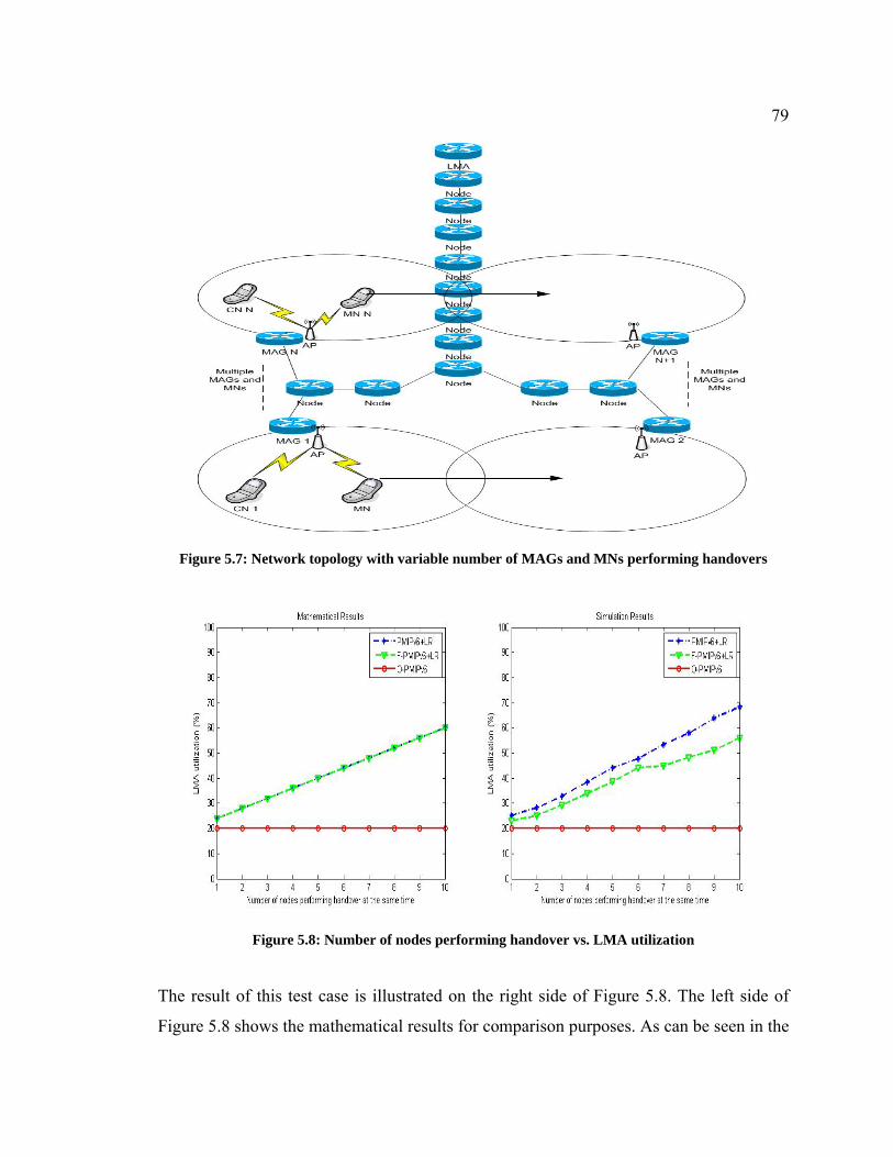
79
Figure 5.7: Network topology with variable number of MAGs and MNs performing handovers
Figure 5.8: Number of nodes performing handover vs. LMA utilization
The result of this test case is illustrated on the right side of Figure 5.8. The left side of
Figure 5.8 shows the mathematical results for comparison purposes. As can be seen in the

80
simulation results, that in both PMIPv6 and F-PMIPv6, LMA utilization is high and
increases dramatically given that number of MNs performing handover increases. This is
due to the fact that portion of the data packets after handover passes through LMA until
LR is established. It can be seen also that when the number of MN performing handovers
is 6 then we have a relatively high utilization. This is due to the fact that, it happened that
there was not a lot of dropped packets and few retransmissions which resulted in most of
the packets received by the LMA causing its high utilization. In case of O-PMIPv6, it can
be seen that LMA utilization stays at the default value of 20% independently of the
number of nodes performing handover. This is due to the fact that LR is established prior
to handover, therefore all the packets sent by MN after being attached to the new MAG
are forwarded on the optimal path.
It is worth noting that one may see that PMIPv6 and F-PMIPv6 curves don’t overlap each
other exactly as expected in the mathematical. The reason is that in the case of F-
PMIPv6, packets sent from MN are forwarded immediately from MAG 1 to MAG 2 to go
on the non-optimal path to LMA. This process gives high probability of dropping packets
and more steady traffic received by the LMA resulting in the above utilization. While in
the case of PMIPv6, packets are buffered at MAG1 until PBA is received, then all
packets are forwarded to LMA. This has less number of nodes to go through and high
arrival rate in small period of time at LMA. This is the reason why utilization is a bit
higher than F-PMIPv6. However, the O-PMIPv6 curve in the simulation model matches
exactly the curve in the mathematical model and this is due to the reason that LMA
utilization is not affected for the reasons stated above. Generally, the curve trends in both
models are similar as well as the fact that O-PMIPv6 performs better than F-PMIPv6 and
PMIPv6 in both models.
5.4.2 Case 2: Host Packet Sending Rate
The LMA utilization is measured against the host (MN) packet sending rate. The packet
sending rate is varied from 5 to 30 pkts/s. The congestion level of the network is set by
external traffic sending at 30 pkt/s. The size of any data packet is 1000 bytes. The number
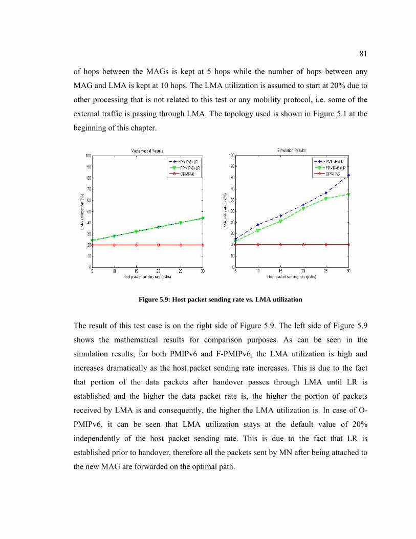
81
of hops between the MAGs is kept at 5 hops while the number of hops between any
MAG and LMA is kept at 10 hops. The LMA utilization is assumed to start at 20% due to
other processing that is not related to this test or any mobility protocol, i.e. some of the
external traffic is passing through LMA. The topology used is shown in Figure 5.1 at the
beginning of this chapter.
Figure 5.9: Host packet sending rate vs. LMA utilization
The result of this test case is on the right side of Figure 5.9. The left side of Figure 5.9
shows the mathematical results for comparison purposes. As can be seen in the
simulation results, for both PMIPv6 and F-PMIPv6, the LMA utilization is high and
increases dramatically as the host packet sending rate increases. This is due to the fact
that portion of the data packets after handover passes through LMA until LR is
established and the higher the data packet rate is, the higher the portion of packets
received by LMA is and consequently, the higher the LMA utilization is. In case of O-
PMIPv6, it can be seen that LMA utilization stays at the default value of 20%
independently of the host packet sending rate. This is due to the fact that LR is
established prior to handover, therefore all the packets sent by MN after being attached to
the new MAG are forwarded on the optimal path.

82
It can be noticed here also that PMIPv6 utilization is slightly higher than F-PMIPv6. This
is due to the same reason mentioned in the previous test case. It is worth noting that one
may see that PMIPv6 and F-PMIPv6 curves don’t overlap each other exactly as expected
in the mathematical but the O-PMIPv6 curve in the simulation model matches exactly the
curve in the mathematical model. These are for the same reasons stated in the previous
test case. Generally, the curve trends in both models are similar as well as the fact that O-
PMIPv6 performs better than F-PMIPv6 and PMIPv6 in both models.

83
Chapter 6
Conclusions and Future Work
In the last chapter, an overview of the contributions of this thesis is presented. Then,
some limitations of the proposed protocol are discussed and finally, recommendations for
future work are made.
6.1 Overview of the Protocol and Main Contributions
The main objective of this research was to develop a NETLMM protocol that will fix
issues around LR handover management in the basic PMIPv6 domain.
In the case of PMIPv6, when an MN performs a handover from one Access Network to
another Access Network, then the MN will face some downtime in which no packets can
be sent or received. Moreover, the LR session between MN and its CN will be torn down
with this handover and will need to be re-established from the beginning after the
handover is completed. As a result, longer handover delay and packet loss, more
signaling, and a lot of data packets will go on the non-optimal path until the LR is re-
established again wiich will cause higher utilization of core network elements such as
LMA.
In the case of F-PMIPv6, the NMAG on the new Access Network will have the handover
information required for the MN prior to the exchange of messages between NMAG and
LMA. This will save some handover delay and also will establish a tunnel between
NMAG and PMAG allowing for packets to be sent and received by the MN during
handover and avoiding packet loss. However, the problem of delay LR session
established and increased signaling is still there as the LR session will be re-established
after MN handover is completed.

84
In the case of O-PMIPv6, the LR information is carried with the messages exchanged
between PMAG and NMAG allowing for the NMAG not only to reduce handover delay
of MN and minimize packet loss, but also to carry on the LR session. This will result in
less signaling when looking at MN and LR handover as a single handover procedure. In
addition, the delay till the LR is established is minimal which will cause all the data
packets to go on the optimal path saving the core network elements from excess
utilization.
In this research, O-PMIPv6 has been developed details, and proved mathematically to be
superior as compared to PMIPv6 and F-PMIPv6 in the area of total handover delay,
signaling cost and LMA utilization. Finally, an extra piece of evidence has been added by
simulating O-PMIPv6, along with the other mentioned mobility protocols, in the NS2
environment and was shown that it is still a better protocol to use over PMIPv6 and F-
PMIPv6.
6.2 Limitations
The proposed protocol works well and has a major improvement in multiple performance
factors such as LR handover delay, signaling and network utilization as proved
theoretically and practically. However this protocol poses some limitations as listed
below.
• This protocol works in a single-LMA domain; however, multiple-LMA domain
handover might pose some problems. The reason is that in multiple-LMA domain,
the two MAGs involved in a handover may be associated with different LMA’s.
As a result, security becomes a concern as information between the MAGs, such
as MN context, may need to be shared. In addition, the LMA may be under the
control of a different operator which can be another boundary for information
sharing.
• Buffering is needed on MAGs. Therefore if the packet rate is very high then the
buffer may run out of room which will result in packet loss. In the case of O-

85
PMIPv6 the use of buffer is minimum as LR session is established quickly so
packets can be sent/received directly from the remote MAG. However buffering
will be needed for a short period when the PMAG signal degrades and MN is
starting its attachment to the NMAG.
• Inter-domain handover may be another limitation. The reason is that when MN
handover across different PMIPv6 domains, then different prefix may be assigned
to MN. In that case, the prefix that has been communicated between the MAGs
involved in the handover may no longer be valid and as a result the NMAG has to
wait for the PBU/PBA exchange with LMA before the new prefix is assigned to
the MN. In that case, the additional handover delay for accomplishing that will be
added to the total delay and this case will be similar to a regular PMIPv6
handover delay as there is a new address configuration and LR session will be
established after that.
6.3 Future Work
For future work, several recommendations can be followed to enhance this protocol and
make it more practical. Below is a list of recommended future work.
• Analyze and modify O-PMIPv6 to work when MN performs handover in a
multiple-LMA domain or across inter-PMIPv6. This is done by having an
improved mechanism for security association and for shared prefixes across
domain
• Buffering can be split between the MAGs that are involved in O-PMIPv6
operation by coming up with an algorithm that assigns the data packet to the right
MAG to be buffered in.
• Improving performance by performing a bulk MN handover when multiple MNs
with LR sessions are performing handover simultaneously.

86
• Analyze and simulate O-PMIPv6 in the case of reactive mode. Although, the
discussion is similar but it will be wise to implement it and test to see the
difference between the predictive and reactive modes in the case of O-PMIPv6.
• Performing scalability analysis and simulation on O-PMIPv6 by increasing the
number of MNs performing handovers to be closer to deployment values. This is
to ensure that performance is still exhibited in large networks.
• Studying whether security is an issue in O-PMIPv6, in addition to implementing a
security scheme in O-PMIPv6 network and investigating the impact of the
overhead introduced when security measures are added to the protocol.
• Analyze and simulate O-PMIPv6 when there are two performance factors
involved at the same time. Example of this can be having a background traffic, i.e.
network congestion, as the same time as multiple MNs performing a handover
from one MAG to another at the same time.
References
[1] Lee, K., Han, Y., and Shin, M., “Handover Latency Analysis of a Network-Based
Localized Mobility Management Protocol”, IEEE international conference on
communications (ICC2008), pp. 1-6, June 2009.

87
[2] Yokota, H., Chowdhur, K., Koodli, R., Patil, B., Xia, F.,"Fast Handovers for Proxy
Mobile IPv6", RFC 5949, Sept 2010.
[3] Liebsch, M., Muhanna, A., and Blume, O.,"Transient Binding for Proxy Mobile
IPv6", RFC 6058, Mar 2011.
[4] Yokota, H., Chowdhur, K., Koodli, R., Patil, B., Xia, F.," Fast Handovers for Proxy
Mobile IPv6", RFC 5949, Sept 2010.
[5] Liebsch, M., "PMIPv6 Localized Routing Problem Statement", draft-ietf-netext-
pmip6-lr-ps-02, Jan 2010.
[6] Loureiro, P., "Proxy Mobile IPv6 Localized Routing", draft-loureiro-netext-pmipv6-
ro-02.txt, Mar 2010.
[7] Krishnan, S., Koodli, R., Loureiro, P., Wu, Q., Dutta, A., "Localized Routing for
Proxy Mobile IPv6", draft-ietf-netext-pmip-lr-01, Oct 2010.
[8] Choi, Y. and Chung, T., “Enhanced Light Weight Route Optimization in Proxy
Mobile IPv6”, Proc. The Fifth International Joint Conference on INC, IMS and IDC, pp.
501-504, Aug 2009.
[9] Han, B., Lee, J., Lee, J., and Chung, T., “PMIPv6 Route Optimization Mechanism
using the Routing Table of MAG”, Proc. The Third International Conference on Systems
and Networks Communications, pp. 274–279, Oct 2008.
[10] Le, D., Fu, X., Hogrefe, D., “A Review of Mobility Support Paradigms for the
Internet”, IEEE Communications Surveys and Tutorials, Volume 8, No. 1, First Quarter,
pp. 38-51, Jul 2006.
[11] Johnson, D., Perkins, C., and Arkko, J.,"Mobility Support in IPv6", RFC 3775, June
2004
88
[12] Thomson, S., Narten, T., and Jinmei, T., "IPv6 Stateless Address
Autoconfiguration", RFC 4862, Sept 2007.
[13] Hinden, R., and Deering, S., "IP Version 6 Addressing Architecture", RFC 4291,
Feb 2006
[14] Morand, L., Tessier, S., “Global mobility approach with Mobile IP in “All IP”
networks”, IEEE international conference on communications (ICC 2002), pp 2075-9
vol.4, May 2002.
[15] Soliman, H., Castelluccia, C., ElMalki, K., and Bellier, L., "Hierarchical Mobile
IPv6 (HMIPv6) Mobility Management", RFC 5380, Oct 2008.
[16] Afifi, H., and Zeghlache, D. “Applications & Services in Wireless Networks”, 2nd
ed., INT, Evry, France, pp. 25-27 July 2001.
[17] Koodli, R., Ed, "Fast Handovers for Mobile IPv6", RFC 5568, July 2009.
[18] Gundavelli, S., Leung, K., Devarapalli, V., Chowdhury, K., and Patil, B., "Proxy
Mobile IPv6", RFC 5213, Aug 2008.
[19] Krishnan, S., Koodli, R., Loureiro, P., Wu, Q., and Dutta, A., "Localized Routing for
Proxy Mobile IPv6", draft-krishnan-netext-pmip-lr-01, Oct 2010.
[20] Loureiro, P., and Liebsch, M., "Proxy Mobile IPv6 Localized Routing", draft-
loureiro-netext-pmipv6-ro-02, March 2010.
[21] Sri, L., Chung, T., “A performance analysis on Route Optimization for Proxy
Mobile IPv6”, IEEE international conference on communications (ICC2009), pp1-6, June
2009.
[22] Zhou, D., Zhang, H., Xu, Z., and Zhang, Y., “Evaluation of Fast PMIPv6 and
Transient Binding PMIPv6 in Vertical Handover Environment”, IEEE international
conference on communications (ICC 2010), pp. 1-5, Jul 2010.

89
[23] Makaya, C. and Pierre, S., “An Analytical Framework for Performance Evaluation
of IPv6-Based Mobility Management Protocols”, IEEE transactions on wireless
communications, Vol. 7, No. 3, pp 972-983, Mar 2008.
[24] Kim, S., Lee, J., and Chung, T., “Performance Analysis of Fast Handover schemes
for Proxy Mobile IPv6”, The Fourth International Conference on Systems and Networks
Communications, pp. 37-48, Sept 2009.
[25] Lee, J, Chung, T, and Gundavelli,, S., “A Comparative Signaling Cost Analysis of
Hierarchical Mobile IPv6 and Proxy Mobile IPv6”, In Proc. of IEEE International
Symposium on Personal, Indoor and Mobile Radio Communications (PIMRC) 2008, pp.
1–6, Sept 2008.
[26] Kleinrock, L, “Queuing Systems, Vol 1: Theory”, Wiley Interscience, 1st Ed. 1975.
[27] Ns-2. The Network Simulator, version 2.29. http://www.isi.edu/nsnam/ns/, Nov
2005.
[28] National Institute of Standards and Technology (NIST), Mobility Extension for
NS-2, http://www.nist.gov/itl/antd/emntg/ssm_tools.cfm, Aug 2009.
[29] Choi, H., Proxy Mobile Ipv6 in ns-2.29. http://commani.net/pmip6ns, Aug 2009.
[30] Lee, H., Lim, J., and Chung, M., “A competent global mobility support scheme in
NETLMM”, International Journal of Electronics and Communications, doi:
10.1016/j.aeue.2008.07.010, On-line published Aug 2008.
[31] Lee, H., Chung, M., Pack, S., and Gundavelli, S., “Shall we apply paging
technologies to Proxy Mobile IPv6 ?”, In Proc. of ACM International Workshop on
Mobility in the Evolving Internet Architecture (MobiArch) 2008, pp. 37–42, Aug 2008.
[32] Pack, S. and Y. Choi, “A study on performance of Hierarchical Mobile IPv6 in IP-
based cellular networks”, IEICE Trans. Commun., vol.E87-B, no.3, pp 462–469, Mar
2004.
90
[33] Magagula, L. and Anthony, H., "IEEE802.21 optimized handover delay for Proxy
Mobile IPv6", 10th International Conference on Advanced Communication Technology,
pp. 1051-1054, Feb 2008.
[34] Ling-Jiao, W., Hua G., Bin, D., and Yong-xin, S., , "Research of Enhanced Route
Optimum Algorithm for PMIPv6", 4th International Conference on Wireless
Communications, Networking and Mobile Computing (WiCOM 2008), pp. 12-14 Oct.
2008.
[35] Magagula, L. and Anthony, H., "Early Discovery and Pre-authentication in Proxy
MIPv6 for Reducing Handover Delay", Third International Conference on Broadband
Communications, Information Technology & Biomedical Applications, pp. 23-26 Nov.
2008.
[36] P´erez-Costa, X., Torrent-Moreno, M., and Hartenstein, H., “A performance
comparison of mobile IPv6, hierarchical mobile IPv6, fast handovers for mobile IPv6 and
their combination,” ACM Mobile Computing and Commun. Rev., vol. 7, no. 4, pp. 5-19,
Oct. 2003.
[37] Gwon, Y., Kempf, J., and Yegin, A., “Scalability and robustness analysis of mobile
IPv6, fast mobile IPv6, hierarchical mobile IPv6, and hybrid IPv6 mobility protocols
using a large-scale simulation,” in Proc. IEEE Int. Conf. on Commun. (ICC’04), vol. 7,
pp. 4087-4091, Jun. 2004
[38] P´erez-Costa, X., Schmitz, R., Hartenstein, H., and Leibsch, M., “A MIPv6, FMIPv6
and HMIPv6 handover latency study: analytical approach,” in Proc. IST Mobile and
Wireless Commun. Summit, pp. 100- 105, Jun. 2002
[39] N. Moore, “Optimistic duplicate address detection,” IETF RFC 4429, Apr. 2006.
[40] Koodli, R. and Perkins, C. E., “Fast handovers and context transfers in mobile
networks,” ACM Mobile Computing and Commun. Rev., vol. 31, no. 5, Oct. 2001.


![A Novel Approach to Reduce Handover Latency in Proxy ... · This makes force to improve ... PMIPv6 Route Optimization focuses the problem of overhead [11]. To solve this problem,](https://static.fdocuments.us/doc/165x107/5ea5d07c2513426621261b0f/a-novel-approach-to-reduce-handover-latency-in-proxy-this-makes-force-to-improve.jpg)