O Aim of the lecture Inductors Behaviour in circuits Energy storage Comparison with Capacitors V...
29
o Aim of the lecture Inductors Behaviour in circuits Energy storage Comparison with Capacitors V vs i Energy Use in Circuits LR time constant sparks LCR Circuit Oscillations Filters o Main learning outcomes familiarity with Inductors in circuits i and V LR curves Energy storage basic LC and LCR circuit Concept of filters Lecture 10
-
Upload
douglas-watkins -
Category
Documents
-
view
216 -
download
0
Transcript of O Aim of the lecture Inductors Behaviour in circuits Energy storage Comparison with Capacitors V...

o Aim of the lecture Inductors
Behaviour in circuits Energy storage
Comparison with Capacitors V vs i Energy
Use in Circuits LR time constant sparks
LCR CircuitOscillationsFilters
o Main learning outcomes familiarity with
Inductors in circuits i and V LR curves Energy storage basic LC and LCR circuit Concept of filters
Lecture 10

Reminder:o an inductor, as used in electronics
is typically a coil of wire wound on a core The core increases the inductance by r
o Real inductors must have resistance because the wire has resistance
o In fact they also have ‘stray’ capacitance, but we will ignore this
inductor
Resistor (resistance of wire in coil)
L = r0N2A/l
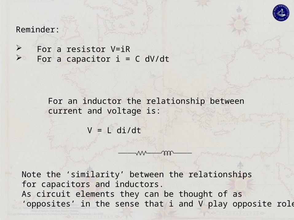
Reminder:
For a resistor V=iR For a capacitor i = C dV/dt
For an inductor the relationship betweencurrent and voltage is:
V = L di/dt
Note the ‘similarity’ between the relationshipsfor capacitors and inductors.As circuit elements they can be thought of as‘opposites’ in the sense that i and V play opposite roles

For an inductor the relationship betweencurrent and voltage is:
V = L di/dt
So:o If the current is constant, then V=0
The inductor behaves simply like a (perfect) wireo If there is current flowing, then to reduce it to zero
requires a voltage as di/dt ≠ 0
[For a capacitor with a voltage on it, a current must flow for the voltage to reduce to zero, as Q=CV – similar]

So:o If the current is constant, then V=0
The inductor behaves simply like a (perfect) wireo If there is current flowing, then to reduce it to zero
requires a voltage as di/dt ≠ 0
Why?
because there is energy stored in the inductor when it has a current flowing through it, Just like a capacitor has energy stored in it when it has a voltage across it.
Work done = ∫ Power dt = ∫ iVdt = ∫ i(Ldi/dt)dt = ∫ iLdi = ½Li2
Energy stored, E = ½Li2
Capacitor Energy stored, E = ½CV2

Energy stored, E = ½Li2
Capacitor Energy stored, E = ½CV2
Recall that there is NO energy stored in a resistor
A resistor dissipates energy, it produces heat
Inductors DO NOT dissipate any energyCapacitors DO NOT dissipate any energy These circuit elements can ABSORB energy But it can come out again, it is only stored
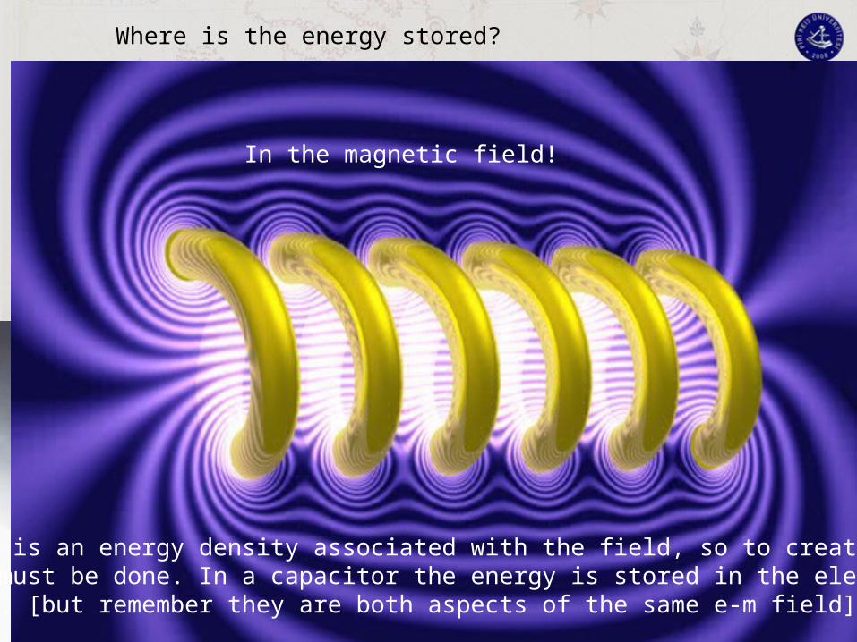
Where is the energy stored?
In the magnetic field!
There is an energy density associated with the field, so to create itwork must be done. In a capacitor the energy is stored in the electricfield, [but remember they are both aspects of the same e-m field]
If the current flowing decreases, then the stored energy must decrease, the ‘excess’ must go somewhere.
It is absorbed by the circuit that is changing the current. The inductor does work ON the circuit

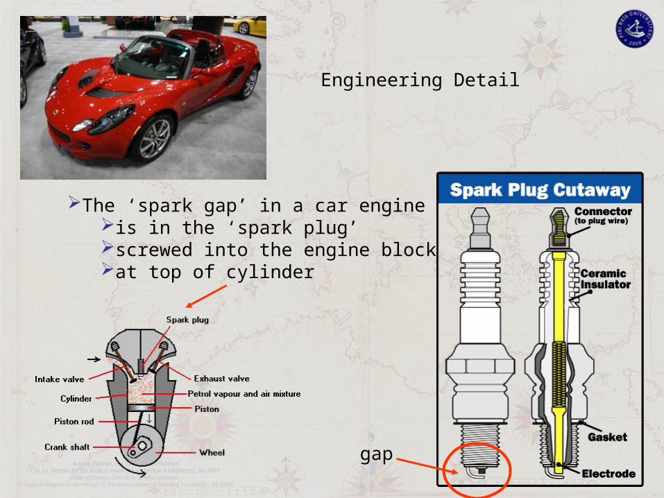
This car relies on an inductor to make the (petrol) engine run - why? – it is used to make the spark to ignite the petrol

A petrol engine (not a diesel) needs a sparkto ignite the petrol. An inductor is used.[in fact some modern cars do it differently, but still common]
When the switch is closed, the voltage across and the current through the inductor will look like this
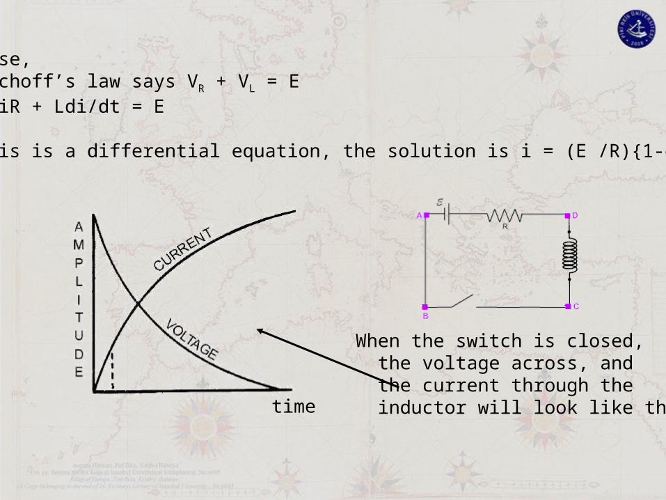
When the switch is closed, the voltage across, and the current through the inductor will look like this
Because, Kirchoff’s law says VR + VL = E so iR + Ldi/dt = E
this is a differential equation, the solution is i = (E /R){1-e-t/(R/C)}
time
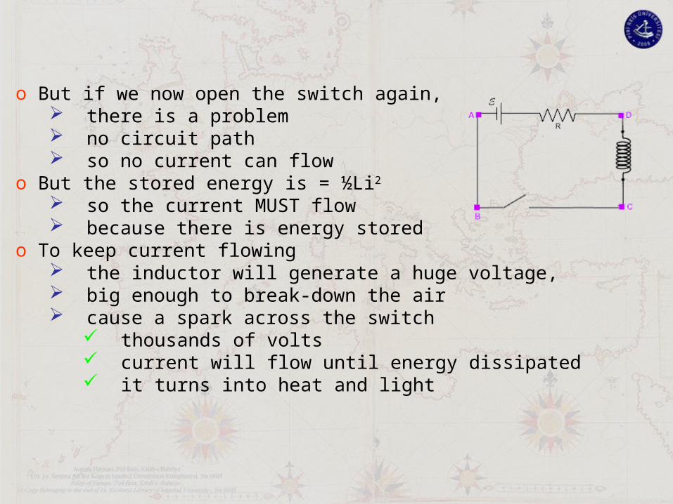
o But if we now open the switch again, there is a problem no circuit path so no current can flow
o But the stored energy is = ½Li2 so the current MUST flow because there is energy stored
o To keep current flowing the inductor will generate a huge voltage, big enough to break-down the air cause a spark across the switch
thousands of volts current will flow until energy dissipated it turns into heat and light

o But if we now open the switch again, there is a problem no circuit path so no current can flow
o But the stored energy is = ½Li2 so the current MUST flow
o To keep current flowing the inductor will generate a huge voltage, big enough to break-down the air cause a spark across the switch
thousands of volts current will flow until energy dissipated
o Add a second gap, smaller than the switch gapIt will break down firstThe smaller gap is the ‘spark gap’Located where the spark is needed
Because:
The ‘spark gap’ in a car engineis in the ‘spark plug’screwed into the engine blockat top of cylinder
gap
Engineering Detail

Time after switch closed
VL = V0e-t/(L/R) IL = (V0/R){1-e-t/(L/R)}
V0
R
L VL
IL
switch
I or V
The sparking situation is ‘abnormal’, it ismore common to be using the components ina ‘controlled way. Sparks are usually bad!

Time after switch closed
Vc = V0e-t/CR IC = (V0/R){1-e-t/CR}
V0
R
C VC
IC
switch
I or V
Provided that L/R = RC then the shape of theI and V curves simply swap
note ‘similarly’ in behaviour of L and C

Time after switch closed
VL = V0e-t/(L/R) IL = (V0/R){1-e-t/(L/R)}
V0
R
L VL
IL
switch
I or V
Provided that L/R = RC then the shape of theI and V curves simply swap
note ‘similarly’ in behaviour of L and C

Time after switch closed
Vc = V0e-t/CR IC = (V0/R){1-e-t/CR}
V0
R
C VC
IC
switch
I or V
Provided that L/R = RC then the shape of theI and V curves simply swap
note ‘similarly’ in behaviour of L and C

Capacitors and Inductors are complementary devices (Often)
o They can be ‘energised’ and ‘emptied of stored energy’o This is called charging and dischargingo (but recall this is NOT a statement about net electric charge)
The relationship between voltage and current is:
o V=iR resistorso V=Ldi/dt inductorso i=CdV/dt capacitors
o Note that only resistors can ‘use’ energy Dissipate it as heat
Now consider using inductors and capacitors in together:

V0
L
C VC
ILC
switch
o In the circuit below, as shown, the capacitor will energise (charge) after a ‘long’ time VC = V0. ILC = 0
So the Energy stored in the circuit is E= ½CVC2

V0
L
C VC
ILC
switch
o Now change the switch position, as shown below the capacitor is energised, E = ½ CVC
2
VC = V0. ILC = L dILC/dt ≠ 0
o But now there is an inductor connected across the capacitoro There is a voltage VC across L
Current must flowo As current grows, the voltage across capacitor will decrease
Because Q=CV and I = dQ/dt

V0
L
C VC
ILC
switch
o After some time, the capacitor will be fully de-energied the capacitor has no energy, E = ½ CVC
2 = ½ C 02 = 0 VC = 0. ILC = maximum = ILC
max
o As there is current flowing through an inductoro There is energy stored in its magnetic field
EL = ½ L(ILCmax)2
o As no energy can be lost in this circuit (no resistance!) EL = ½ L(ILC
max)2 = ½ CV02
so ILCmax = V0 √(C/L)

V0
L
C VC
ILC
switch
o All the energy is now stored in the inductor EL = ½ CV0
2
VC = 0 = VL
ILC =V0 √(C/L)
o As there is current flowing through the capacitoro It will energise (charge up)
The current will decrease as the energy is transferred back to the capacitor
o Eventually the current reaches zero and EL = ½ L(ILC)2 = ½ L02 =0 EC = ½ CV0
2

V0
L
C VC
ILC
switch
o The energy oscillates back and forth between The inductor, stored as energy in magnetic field The capacitor, stored as energy in the electric field (and between the extremes, also shared between L and C)
time
ILC
VC
V0 √(C/L)V0
The final answeris that the voltagesand currents in thiscircuit oscillate likea sine wave
But phase shifted

V0
L
C VC
ILC
switch
Write Kirchoff’s voltage law round the loop
V = 0 = LdILC/dt + Q/C
take derivative wrt to time
V = 0 = Ld2ILC/dt + (1/C)dQ/dt
= Ld2ILC/dt + ILC/C
You will recognise this as SHM with 0 = 1/LCOr you should recognise it!!

V0
L
C VC
ILC
switch
0 = Ld2ILC/dt + ILC/C
ILC = {V0√(C/L)} sin(0t+)
0 = 1/√(LC)
is found from initial boundary conditions:
As ILC = minimum = 0 when t=0, =
But is not very importantfor this case, it just givesa definition of t=0
really matters when it is used to show the difference between thedifferent voltages and currents in the circuit, so the shift between
Current and voltage in capacitor is /2Similarly for the inductor, but it is –/2The voltages on the Capacitor and inductor are different.
.
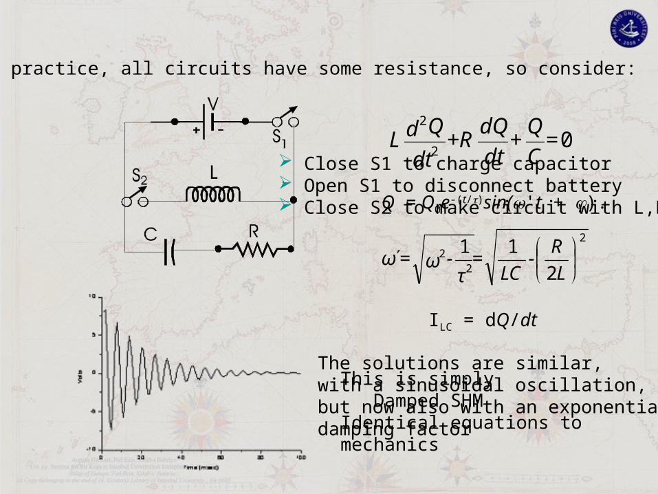
In practice, all circuits have some resistance, so consider:
The solutions are similar,with a sinusoidal oscillation,but now also with an exponentialdamping factor
This is simply Damped SHMIdentical equations tomechanics
02
2
=C
Q+
dt
dQ+R
dt
QdL
Q = Q0e‑(t/)sin('t + ).
2
22
2
11
L
R-
LC=τ-ω=ω
ILC = dQ/dt
Close S1 to charge capacitor Open S1 to disconnect battery Close S2 to make circuit with L,R,C
VC
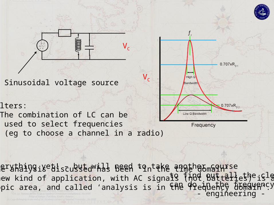
VCSinusoidal voltage source
Filters: The combination of LC can be used to select frequencies (eg to choose a channel in a radio)
All the analysis discussed has been ‘in the time domain’This new kind of application, with AC signals (not batteries) is a wholenew topic area, and called ‘analysis is in the frequency domain’.
You don’t know everything yet! – but will need to take another course to find out all the clever things you can do in the frequency domain - engineering -

Vout/Vin
frequency
Some real filters
Band-stop filter
Enjoy!