o (' 9 '3v:-'lcweb2.loc.gov/master/mbrs/recording_preservation... · The BGW Model 100~ is one of...
15
I I SYSTEMS 13:30 South Yukon Avenue California 90250 (213) 973-8090 #66- 4 494 100B TEST REPORT DI'.':'::: : I - , 53 - "7 q 7:SCENICIAN D.( _ (,J . S::2RIP.L NO. 7980 'S :"'INE VOLTAGE: fZ Qi/ A< -, Power at (0.1% Ch. Ch. 2 Mono - 8 ohms - volts out 2.3.C::" v L3S;V "'1. 3£/ Power o C(,,,uJ Power at cli? (O.lS%T.E.D.) 7CJ0 (' 9_'3v:-' 4 ohms - volts out \. Cf Lv Power 1C; -w T.H.D. 50 watts - 8 (20.1 vo 1 t s ) • COL-.g % 28 :iz ( '7 ( % S ohms -3 dB F:-ec. ue::cy <:f <7 kE:z / Ie k2..z :"evel Noise 2'] 22 -:0 20 kHz (' <-{ .v. Quiescent Power lJat-:s (
Transcript of o (' 9 '3v:-'lcweb2.loc.gov/master/mbrs/recording_preservation... · The BGW Model 100~ is one of...

I
~ I
SYSTEMS
13:30 South Yukon Avenue 2awt~orne, California 90250 (213) 973-8090 ~e2.ex #66- 4 494
~ODEL 100B TEST REPORT
DI'.':'::: : I - , 53 - "7 q 7:SCENICIAN D.( _(,J . ~~-=~~---------~-----------
S::2RIP.L NO. 7980 'S z.._~
:"'INE VOLTAGE: fZ Qi/A<
- ,Power at ~lip (0.1% T.~.D.) Ch. Ch. 2 Mono-8 ohms - volts out 2.3.C::" v L3S;V ~::S "'1. 3£/Power o C(,,,uJ
Power at cli? (O.lS%T.E.D.) 7CJ0 (' 9_'3v:-'
4 ohms - volts out \. Cf Lv 19.~·tIPower
1C;-w q~1!-.1T.H.D. 50 watts - 8 or~s
(20.1 vo 1 t s )
• COL-.g %28 :iz ~:J k~z ( '7 ( %
Silla~: 3~g~a: 3andwidt~ S ohms
- 3 dB F:-ec. ue::cy <:f <7 kE:z / Ie k2..z
~c~se :"evel SU~?ut Noise Vol~age 2'] 22 -:0 20 kHz (' <-{ .v.
Quiescent Power lJat-:s (

SERIAL NUMBER
THROUGH
OWNER'S MANUAL
MODEL 100B
PROFESSIONAL POWER AMPLIFIER
TABLE OF CONTENTS
DESCRIPTION
Important
Description
Specifications
Unpacking and Set Up
Input Connections
Input Transformers
Output Connections
Power Mains Connection
Power Mains Voltage Conversion
Operation
Schematic Diagram, Amplifier
Schematic Diagram, Power Supply
Parts List
Parts List, PackiGg Contai~er
Warranty
FORM NUMBER
00600
00800
00900
02500
03000
03100
03500
040CO
04100
05200
09900
10000
10300
10400

00600
- IMPORTANT
PLEASE READ THIS PAGE BEFORE OPERATING
YOUR
BGW POWER AMPLIFIER
Your new BGW power amplifier is designed to provide years of
trouble free performance. Observing these few precautions
will insure proper operation.
All connections should be made to the power amplifier with the power OFF.
Speaker fuses should be used to afford maXlmum speaker protection.
Never connect the output of one channel to that of another.
Never connect a direct short from the output of any channel to ground.
Connect the power cord to the proper voltage mains as indicated on the serial number tag. Conversion to another voltage requires internal rewiring.
Do not remove the amplifierts cover. ArnDlifiers may not be covered under warranty if they are tampered with. There are NO adjustments within. Potentially lethal voltages exist within the amplifier. Refer all service work to an authorized BGW service station.

uu~uu
DESCRIPTION
The BGW Model 100~ is one of the most advanced solid state, fully complementary, brldgeable, stereo power amplifiers available.
Features of the Model 100B include LED metering, separate circuit and chassis grounds, XLR and ~" input connectors with transformer sockets, and small size.
The front panel includes two vertical rows of four red LEDs, one row fer each channel. The lower LED in each row is the IDLE indicator or pilot lamp. They will be lit whenever the amplifier is turned on.
The two upper LEDs in each row clipping utilize an exclusive BGW circuit. Whenever either channel of the 100B is driven into clipping, a corresponding indicator lights and remains lit for 0.25 seconds. These indicators, which actually indicate loss of feedback, tell the operator that the amplifier is being overdriven and can be invaluable to the engineer who must be sure that every component in his system is producing a clean, distortion-free signal. An inadvertant short-circuited output (with signal) will cause the LED to remain on until the short is removed.
The middle LEDs are connected to a circuit employing a quad comparator integrated circuit to provide an audio level indication of 0.5% and 50% of maximum power output. They provide a valuable tool for total system evaluation in multiple amplifier installations.
Both the circuit and chassis grounds are connected to separate barrier strin terminals on the rear of the amplifier. They are connected together by a removeable link. By removing The link, the circuit grounds of all active units (amplifiers, preamplifiers, mixers, etc.) can be tied to earth ground at a common poinT. This aids in eliminating ground loops.
Either XLR-type of ~-inch phone plugs may be used for input connections. If plug-in transformers are used, the XLR-type connectors are connecTed. If not, jumpers must be employed in the transformer sockets. See sections 03000 anc 03100 for details.
The size of the Model 100B is convenient for a wide variety of applications. However, please nete the following precautions:
1) Do not use the front panel as the sole support for the amplifier. Side rails or rack shelves should be employed.
2) Do not stack Model 100B amplifiers. A minimum of 1 3/4 inches above each amplifier should be provided fer free ai~ circulation.

00800
The output stages of your amplifier use the most advanced type of transistors available. These large geometry, complementary, power devices have large safe operating area and extended power bandwith. Electrostatic and other highly reactive speaker systems present no difficulties for the Model 100B. The aluminum heat sink has a total radiating surface of 330 square inches (2130 cm 2 ).
All of the semiconductors in the output area are in intimate contact with the heat sink. The bias circuit is also mounted on this isotherm to provide rock steady bias stability with temperature.
The voltage gain circuits are also mounted on the same circuit board. A true operational amplifier integrated circuit, hermetically sealed in a metal can, acts as the front end.
The op-amp is a special unit featuring high speed (15MHz) and a high slew rate (50 volts/microsecond) yet still having very low noise due to its darlington input and careful design. The op-amp stage is followed by a discrete complementary pair acting as an active current source/sink and providing voltage gain. The current source is the ideal way to drive the output stage, which is basically a voltage follower.
This sophisticated circuit design makes for an extremely accurate amplifier. The accuracy of an amplifier is a function of the ratio of the open loop gain to the closed loop gain. In this case, the open loop gain is about 1,000,000. This extremely accurate signal processing enables the amplifier to drive speakers at very high levels while adding absolutely no coloration of its own. Even at milliwatt levels, the output waveform exhibits no sign of crosscver distortion.

00900
SPECIFICATIONS
Intermodulation Distortion:
Small Signal Frequency Response:
Hum and Noise Level:
Input Sensitivity:
InpuT Impedance: t
Damping Factor:
Output Impedance: :)
Power Kequirements :
Semiconductor Complement:
Dimensions:
Weight:
Less than 0.02% from 250 milliwatts to rated power
+0, -3dB, 1 Hz to 90kHz +0, -0.25 dB, 20Hz to 20kHz
Better than 106 dB below 50 watts (unweighted, 20 Hz t o 20kHz )
1.0 volts for maximum power output. Voltage gain 26dB ( 20 times)
15k ohms
Greater than 400 to 1 referenced to 8-ohms @ 1kHz
Designed for any load impedance equal to or greater than 4 ohms
Convertable for 100, 120, 200, 220, or 240 volts A.C., 50 -60Hz
2 Op Amp IC's ( equivalent to 44 transistors each), 24 transistor s, 2 zener diodes, 12 diodes, 8 LED's, 1 quad comparator
1.75-inch by 19-inch standard rack front panel by 11.5 inches deep.
18 Ibs ., (8.2 kg ) net, 22 Ibs., (1 0 kg) shipping

00900
SPECIFICATIONS: BGW MODEL 100B
OUTPUT POWER
50 watts minimum sine wave continuous average power output per channel with both channels driving 8-ohm loads over a power band from 20Hz to 20kHz. The maximum Total Harmonic Distortion at any power level from 250-milliwatts to 50 watts shall be no more than 0.1%.
1kHz Power: 60 watts into 8-ohms per channel, both channels operating, 0.1% Total Harmonic
Distortion
60 'N'atts minimum sine wave continuous average power output per channel with both channels driving 4-ohm loads over a power band from 20Hz to 20kHz. The maximum Total Harmonic Distortion at any power level from 250-milliwatts to 60 watts shall be no more than 0.2%.
1kHz Power: 65 watts into 4-ohms per channel, both channels operating, 0.1% Total Harmonic Distortion
120 watts minimum sine wave continuous average power output monaural driving an 8-ohm load over a power band from 20Hz to 20kHz. The maximum Total Harmonic Distortion at any power level from 250-milliwatts to 120 watts shall be no more than 0.2%.
1kHz Power: 130 watts into 8-ohms, 0.1% Total Harmonic Distortion.
All specifications and features are subject to change without notice.

04100
POWER MAINS VOLTAGE CONVERSION
NOTICE: Voltage conversion should be done by a BGW authorized service station only.
The Model 100B is shipped from the factory wired for either 120/240-volt operation or 100/220-volt operation. The schematic diagrams below indicate the connections for both arrangements. Please note that these connections apply only to transformers marked with part number 0900-0122. For conversion of units with other transformers, please contact the factory.
In addition to changing the connections, two fuses must be changed according to the following table:
100V 120V 200V 220V 240V
Inside Fuse 4A SIB 4A SIB 1.7SA SIB 1.7SA SIB 1.7SA SIB
Outside Fuse 2.SA SIB 2.SA SIB 1.2SA SIB 1.2SA SiB 1.2SA SIB

05200
OPERATION
PRECAUTIONS
1. Speaker destruction is often due to improper equipment operation. This often occurs when someone without the proper appreciation for the components of a high power, high quality music system has the opportunity to change records or adjust levels. The best protection here is caution. Keep the equipment out of the reach of untrained adults and children. Make sure the speaker is properly protected with fuses <Output Connections Section).
2. Never parallel the two amplifier outputs together.
3. When driving any load with an impedance of less than 4 ohms, the load should be isolated from the amplifier with a series capacitor in order to avoid both damage to the load and wasting of output power.
4. If the amplifier continuously blows fuses, something is wrong--do not increase fuse size.
5. Do not connect an imput ground lead to an output ground lead; to do so may cause a ground loop and oscillations.
6. Do not operate the amplifier from power mains which exceed the indicated mains voltage by more than 10%.
7. Never connect the output of the amplifier to another power source such as a battery or power main.
8. Do not expose the amplifier to corrosive chemicals such as lye, soft drinks, salt water, etc. Also, never immerse the amplifier in any liquid.
9. Do not remove the amplifier's cover during operations.
10. _The amplifier. is ndt intended for high frequency-high power use and should not be used for high power at above 20kHz.
11. Neither the amplifier nor any of its leads should be exposed to areas likely to be s~ruck by lightning.
05200
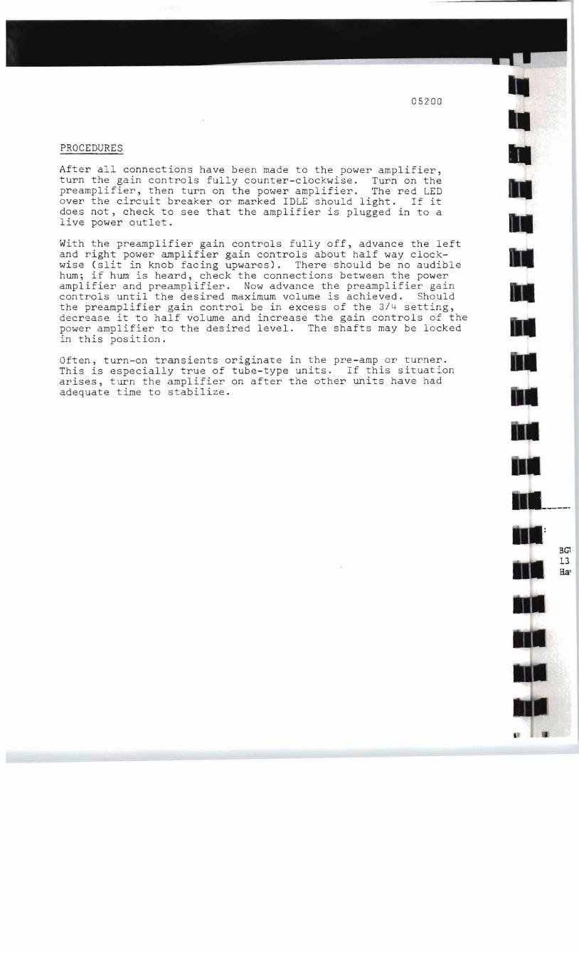
PROCEDURES
After all connections have been made to the power amplifier, turn the gain controls fully counter-clockwise. Turn on the preamplifier, then turn on the power amplifier. The red LED over the circuit breaker or marked IDLE should light. If it does not, check to see that the amplifier is plugged in to a live power outlet.
With the preamplifier gain controls fully off, advance the left and right power amplifier gain controls about half way clockwise (slit in knob facing upwares). There should be no audibl~ hum; if hum is heard, check the connections between the power amplifier and preamplifier. Now advance the preamplifier gain controls until the desired maximum volume is achieved. Should the preamplifier gain control be in excess of the 3/4 setting, decrease it to half volume and increase the gain controls of the power amplifier to the desired level. The shafts may be locked in this position.
Often, turn-on transients originate in the pre-amp or turner. This is especially true of tube-type units. If this situation arises, turn the amplifier on after the other units have had adequate time to stabilize.
BG1 13 Ha'

NOTICE
The parts list had not been printed at the time this amplifier was shipped. For a complete set of parts lists, please complete the mailing label below and return it to:
BGW SYSTEMS 13130 S. Yukon Ave.
Hawthorne, CA. 90250
----------._------_.---------------------------------------------------------------------------
BGW SYSTEMS 13130 S. Yukon Ave. Hawthorne, CA. 90250
/OOB TO:

------------------------
----------------------
--------
SERVICE AUTHORIZATION FORM
PLEASE COMPLETE THIS FORM AS COMPLETELY AS POSSIBLE AND RETURN TO BGW SYSTEMS BEFORE RETURNING UNIT.
NAME: ------------------------------------- PHONE:
ADDRESS: (CITY) (STATE) (ZIP)
UNIT: ---------------------------MODEL SERIAL NUMBER
1. DES CRIBE SYMPTOMS:
2. WHICH CHANNELS (S) EXHIBITS THE PROBLEMS?
3. WHAT OTHER EQUIPMENT WAS INVOLVED?
MANUFACTURER MODEL NO. PREAMP SPEAKERS
4. UNDER WHAT CONDITIONS DOES THE PROBLEM OCCUR (CHECK THOSE THAT APPLY) •
A. ALL THE TIME B. AFTER AWHILE C. AT HIGH VOLUME LEVELS D. AT HIGH TEMPERATURES -- E. OTHER (EXPLAIN)
5. HOW OFTEN DID THE PROBLEM OCCUR?
6. WHAT DID YOU DO TO ISOLATE THE PROBLEM TO THE POWER AMP?
7. FURTHER COMMENTS:
IT IS MORE EXPEDIENT TO CALL YOUR DEALER OR OUR FACTORY EXPLAINING THE NATURE OF YOUR PROBLEM. IN MANY INSTANCES THE PROBLEM CAN BE SOLVED WITHOUT RETURNING THE UNIT TO THE FACTORY. WARNING: THE UNIT MUST BE RETURNED IN AN ORIGINAL FACTORY CONTAINER. IF YOU DO NOT HAVE ONE, WE WILL PROVIDE A REPLACEMENT FOR $14.00. FACTORY AUTHORIZED WARRANTY REPAIR STATIONS ARE LOCATED THROUGHOUT THE U.S. CALL YOUR DEALER OR THE FACTORY FOR THE LOCATION OF THE SERVICE STATION NEAREST YOU.
----------------------------------------------------------------------------
CI
~~P WA:
Pl..of
~.
AD
.PU
!SYSTEMS
Me
Sl13130 SOUTH YUKON AVENUE
HAWTHORNE.I CALIFORN IA 90250 ?\
FOLD HERE
I
I
w
c

-------------------
-----------------
____________________________________ __
------------------------------------------------
------------------------
WARRANTY REGISTRATION
Please fill out and retu-~ this card within 2 weeks f~om date of purchase.
NAME: __________________________________DATE PURCHASED: ______
ADDRESS: ____________________________________PHONE: _________
CITY: _________________________STATE: ____________ZIP: _________
PURCHASED FROM: Dealer
Address
C.l:cy S-ra":e zit'
MODEL NUMBER:
SER~~ NUMBER: ________________ _
PURCHASE PRICE:
For wnat Purpose Is The Unit In~ended?
Home Stud....i-o---Sound ReL~=o~cement Oth~ (explain) ____.:-_-~_-_-_-
....
I= yes, wha~ kind?
wny did you choose a BGW ?ower ampli.fie~?
Dealer Recommendation Magaz~ne Advertisement Sound Quality ----Technical Design
____Friend's Recommendation -Other
COMMENTS:
Is ~his amplifier a replacement for an existing un_-i-.,

-
- -
!SYSTEMS
13130 SOUTH YUKON AVENUE
HAWTHORNE., CALI FO RN IA 90250
,----------------------------------------------------------------------------,~ FOLD HERE