O-360, HO-360, IO-360, AIO-360, HIO-360 & TIO-360 Series
75
Operator’s Manual Lycoming O - 3 6 0 , H O - 3 6 0 , I O - 3 6 0 , A I O - 3 6 0 , H I O - 3 6 0 & T I O - 3 6 0 S e r i e s Approved by FAA 8 th Edition Part No. 60297-12 652 Oliver Street Williamsport, PA. 17701 U.S.A. October 2005 570/323-6181
Transcript of O-360, HO-360, IO-360, AIO-360, HIO-360 & TIO-360 Series

Operator’s Manual
Lycoming
O-360, HO-360,
IO-360, AIO-360,
HIO-360 & TIO-360 Series
Approved by FAA
8th Edition Part No. 60297-12
652 Oliver StreetWilliamsport, PA. 17701 U.S.A.
October 2005570/323-6181

O, HO, IO, AIO, HIO, TIO-360 Series Operator’s ManualLycoming Part Number: 60297-12
©2005 by Lycoming. All rights reserved.Lycoming and “Powered by Lycoming” are trademarks or registered trademarks ofLycoming.
All brand and product names referenced in this publication are trademarks or registeredtrademarks of their respective companies.
For additional information:
Mailing address:
Lycoming Engines652 Oliver StreetWilliamsport, PA 17701 U.S.A.
Phone:
Factory: 570-323-6181Sales Department: 570-327-7268Fax: 570-327-7101
Lycoming’s regular business hours are Monday through Friday from 8:00 AMthrough 5:00 PM Eastern Time (-5 GMT)
Visit us on theWorld Wide Web at:http://www.lycoming.com
Revised June 2007
OPERATOR’S MANUALREVISION
REVISION NO. PUBLICATION PUBLICATION NO. PUBLICATION DATE
60297-12-5O-360, HO-360, IO-360,AIO-360, HIO-360 &TIO-360 Series
60297-12 October 2005
The page(s) in this revision replace, add to, or delete current pages in the operator’s manual.PREVIOUS REVISION CURRENT REVISION
June 2007
Web Page; 3-38
September 2007
3-8, 3-9, 3-11
December 2007
3-4, 3-5
March 2009
1-5; Section 2 Index, 2-3, 2-8, 2-11; 3-5, 3-21, 3-41
December 2009
2-7
©2009 by Lycoming “All Rights Reserved”
Lycoming Engines, a division of AVCO Corporation, a wholly owned subsidiary of Textron Inc.
LYCOMING OPERATOR’S MANUAL
ATTENTION
OWNERS, OPERATORS, AND MAINTENANCE PERSONNEL
���7KLV�RSHUDWRU¶V�PDQXDO�FRQWDLQV�D�GHVFULSWLRQ�RI�WKe engine, its specifications, and detailed information onhow to operate and maintain it. Such maintenance procedures that may be required in conjunction withperiodic inspections are also included. This manual is intended for use by owners, pilots and maintenancepersonnel responsible for care of Lycoming powered aircraft. Modifications and repair procedures arecontained in Lycoming overhaul manuals; maintenance personnel should refer to these for such procedures.
SAFETY WARNING
NEGLECTING TO FOLLOW THE OPERATING INSTRUCTIONS AND TO CARRY OUT PERIODICMAINTENANCE PROCEDURES CAN RESULT IN POOR ENGINE PERFORMANCE AND POWERLOSS. ALSO, IF POWER AND SPEED LIMITATIONS SPECIFIED IN THIS MANUAL ARE EXCEEDED,FOR ANY REASON; DAMAGE TO THE ENGINE AND PERSONAL INJURY CAN HAPPEN. CONSULTYOUR LOCAL FAA APPROVED MAINTENANCE FACILITY.
SERVICE BULLETINS, INSTRUCTIONS, AND LETTERS
Although the information contained in this manual is up-to-date at time of publication, users are urged tokeep abreast of later information through Lycoming Service Bulletins, Instructions and Service Letterswhich are available from all Lycoming distributors or from the factory by subscription. Consult the latestrevision of Service Letter No. L114 for subscription information.
SPECIAL NOTE
The illustrations, pictures and drawings shown in this publication are typical of the subject matter theyportray; in no instance are they to be interpreted as examples of any specific engine, equipment or partthereof.
iii

LYCOMING OPERATOR’S MANUAL
IMPORTANT SAFETY NOTICE
Proper service and repair is essential to increase the safe, reliable operation of all aircraft engines. Theservice procedures recommended by Lycoming are effective methods for performing service operations.Some of these operations require the use of tools specially designed for the task. These special tools must beused when and as recommended.
It is important to note that most Lycoming publications contain various Warnings and Cautions whichmust be carefully read in order to minimize the risk of personal injury or the use of improper servicemethods that may damage the engine or render it unsafe.
It is also important to understand that these Warnings and Cautions are not all inclusive. Lycoming couldnot possibly know, evaluate or advise the service trade of all conceivable ways in which service might bedone or of the possible hazardous consequences that may be involved. Accordingly, anyone who uses aservice procedure must first satisfy themselves thoroughly that neither their safety nor aircraft safety will bejeopardized by the service procedure they select.
iv

LYCOMING OPERATOR’S MANUAL
TABLE OF CONTENTS
Page
SECTION 1 DESCRIPTION 1-1
SECTION 2 SPECIFICATIONS 2-1
SECTION 3 OPERATING INSTRUCTIONS 3-1
SECTION 4 PERIODIC INSPECTIONS 4-1
SECTION 5 MAINTENANCE PROCEDURES 5-1
SECTION 6 TROUBLE-SHOOTING 6-1
SECTION 7 INSTALLATION AND STORAGE 7-1
SECTION 8 TABLES 8-1
LYCOMING OPERATOR’S MANUAL
SECTION 1DESCRIPTION
Page
General.......................................................................................................................................................... 1-1
Cylinders....................................................................................................................................................... 1-1
Valve Operating Mechanism ...................................................................................................................... 1-1
Crankcase ..................................................................................................................................................... 1-1
Crankshaft .................................................................................................................................................... 1-1
Connecting Rods .......................................................................................................................................... 1-2
Pistons ........................................................................................................................................................... 1-2
Accessory Housing ....................................................................................................................................... 1-2
Oil Sump ....................................................................................................................................................... 1-2
Cooling System............................................................................................................................................. 1-2
Induction System.......................................................................................................................................... 1-2
Lubrication System...................................................................................................................................... 1-3
Priming System ............................................................................................................................................ 1-3
Ignition System............................................................................................................................................. 1-3
Counterweight System................................................................................................................................. 1-3
Model Application Table............................................................................................................................. 1-3
LYCOMING OPERATOR’S MANUAL SECTION 1O-360 AND ASSOCIATED MODELS DESCRIPTION
SECTION 1
DESCRIPTION
The O. HO, IO, AIO, HIO, LIO and TIO-360 series are four cylinder, direct drive, horizontally opposed,air-cooled engines.
In referring to the location of the various engine components, the parts are described as installed in theairframe. Thus, the power take-off end is the front and the accessory drive end the rear. The sump section isthe bottom and the opposite side of the engine where the shroud tubes are located the top. Reference to theleft and right side is made with the observer facing the rear of the engine. The cylinders are numbered fromfront to rear, odd numbers on the right. The direction of rotation of the crankshaft, viewed from the rear, isclockwise. Rotation for accessory drives is determined with the observer facing the drive pad.
NOTE
The letter “L” in the model prefix denotes the reverse rotation of the basic model. Example:model IO-360-C has clockwise rotation of the crankshaft. Therefore, LIO-360-C hascounterclockwise rotation of the crankshaft. Likewise, the rotation of the accessory drives ofthe LIO-360-C is opposite those of the basic model as listed in Section 2 of this manual.
The letter “D” used as the 4th or 5th character in the model suffix denotes that the particularmodel employs dual magnetos housed in a single housing. Example: All informationpertinent to the O-360-A1F6 will apply to the O-360-A1F6D.
Operational aspects of engines are the same and performance curves and specifications forthe basic model will apply.
Cylinders – The cylinders are of conventional air-cooled construction with the two major parts, head andbarrel, screwed and shrunk together. The heads are made from an aluminum alloy casting with a fullymachined combustion chamber. Rocker shaft bearing supports are cast integral with the head along withhousings to form the rocker boxes. The cylinder barrels have deep integral cooling fins and the inside of thebarrels are ground and honed to a specified finish.
Valve Operating Mechanism – A conventional type camshaft is located above and parallel to the crankshaft.The camshaft actuates hydraulic tappets, which operate the valves through push rods and valve rockers. Thevalve rockers are supported on full floating steel shafts. The valve springs bear against hardened steel seatsand are retained on the valve stems by means of split keys.
Crankcase – The crankcase assembly consists of two reinforced aluminum alloy castings, fastened togetherby means of studs, bolts and nuts. The mating surfaces of the two castings are joined without the use of agasket, and the main bearing bores are machined for use of precision type main bearing inserts.
Crankshaft – The crankshaft is made from a chrome nickel molybdenum steel forging. All bearing journalsurfaces are nitrided.
1-1
SECTION 1 LYCOMING OPERATOR’S MANUALDESCRIPTION O-360 AND ASSOCIATED MODELS
Connecting Rods – The connecting rods are made in the form RI� ³+´� VHFWLRQV� IURP�DOOR\� VWHHO� IRUJLQJV��They have replaceable bearing inserts in the crankshaft ends and bronze bushings in the piston ends. Twobolts and nuts through each cap retain the bearing caps on the crankshaft ends.
Pistons – The pistons are machined from an aluminum alloy. The piston pin is of a full floating type with aplug located in each end of the pin. Depending on the cylinder assembly, pistons may be machined for eitherthree or four rings and may employ either half wedge or full wedge rings. Consult the latest revision ofService Instruction No. 1037 for proper piston and ring combinations.
Accessory Housing – The accessory housing is made from an aluminum casting and is fastened to the rear ofthe crankcase and the top rear of the sump. If forms a housing for the oil pump and the various accessorydrives.
Oil Sump (Except AIO Series) – The sump incorporates an oil drain plug, oil suction screen, mounting padfor carburetor or fuel injector, the intake riser and intake pipe connections.
Crankcase Covers (AIO Series) – Crankcase covers are employed on the top and bottom of the engine.These covers incorporate oil suction screens, oil scavenge line connections. The top cover incorporates aconnection for a breather line and the lower cover a connection for an oil suction line.
Cooling System – These engines are designed to be cooled by air pressure. Baffles are provided to build up apressure and force the air through the cylinder fins. The air is then exhausted to the atmosphere through gillsor augmentor tubes usually located at the rear of the cowling.
Induction System – Lycoming O-360 and HO-360 series engines are equipped with either a float type orpressure type carburetor. See Table 1 for model application. Particularly good distribution of the fuel-airmixture to each cylinder is obtained through the center zone induction system, which is integral with the oilsump and is submerged in oil, insuring a more uniform vaporization of fuel and aiding in cooling the oil inthe sump. From the riser the fuel-air mixture is distributed to each cylinder by individual intake pipes.
Lycoming IO-360, AIO-360, HIO-360 and TIO-360 series engines are equipped with a Bendix type RSAfuel injector, with the exception of model IO-360-B1A that is equipped with a Simmonds type 530 fuelinjector. (See Table 1 of model application.) The fuel injection system schedules fuel flow in proportion toair flow and fuel vaporization takes place at the intake ports. A turbocharger is mounted as an integral partof the TIO-360 series engines. Automatic waste gate control of the turbocharger provides constant airdensity to the fuel injector inlet from sea level to critical altitude.
A brief description of the carburetors and fuel injectors follows:
The Marvel-Schebler MA-4-5 and HA-6 carburetors are of the single barrel float type equipped with amanual mixture control and an idle cut-off.
The Marvel-Schebler MA-4-5AA carburetor is of the single barrel float type with automatic pressurealtitude mixture control. This carburetor is equipped with idle cut-off but does not have a manual mixturecontrol.
The Bendix-Stromberg PSH-5BD is a pressure operated, single barrel horizontal carburetor, incorporatingan airflow operated power enrichment valve and an automatic mixture control unit. It is equipped with anidle cut-off and a manual mixture control. The AMC unit works independently of, and in parallel with, themanual mixture control.
1-2
LYCOMING OPERATOR’S MANUAL SECTION 1O-360 AND ASSOCIATED MODELS DESCRIPTION
The Bendix RSA type fuel injection system is based on the principle of measuring air flow and using theair flow signal in a stem type regulator to convert the air force into a fuel force. This fuel force (fuelpressure differential) when applied across the fuel metering section (jetting system) makes fuel flowproportional to airflow.
The Simmonds type 530 is a continuous flow fuel injection system. This continuous flow system has threeseparate components:
1. A fuel pump assembly.2. A throttle body assembly.3. Four fuel flow nozzles.
This system is throttle actuated. Fuel is injected into the engine intake valve ports by the nozzles. Thesystem continuously delivers metered fuel to each intake valve port in response to throttle position, enginespeed and mixture control position. Complete flexibility of operation is provided by the manual mixturecontrol, which permits the adjustment of the amount of injected fuel to suit all operating conditions. MovingWKH�PL[WXUH�FRQWURO�WR�³,GOH�&XW�2II´�UHVXOWV�LQ a complete cut-off of fuel to the engine.
Lubrication System – (All models except AIO-360 series). An impeller type pump contained within theaccessory housing actuates the full pressure wet sump lubrication system.
AIO-360 Series – The AIO-360 series is designed for aerobatic flying and is of the dry sump type. A doublescavenge pump is installed on the accessory housing.
Priming System – Provision for a primer system is provided on all engines employing a carburetor. Fuelinjected engines do not require a priming system.
Ignition System – Dual ignition is furnished by two Bendix magnetos. Consult Table 1 for modelapplication.
Counterweight System – Models designated by the numeral 6 in the suffix of the model number (Example:O-360-A1G6) are equipped with crankshafts with pendulum type counterweights attached.
TABLE 1
MODEL APPLICATIONModel Left** Right** CarburetorO-360
-A1A, -A2A, -A3A, -A4A-A1C, -C2D-A1D, -A2D, -A3D, -A4D, -A2E-A1F, -A2F, -A1F6-A1G, -A2G, -A4G, -A1G6-A1H, -A2H, -A4J-A1H6-A1P, -A4P, -B2C, -C4P-A4K, -C1F, -C4F-A4M
S4LN-21S4LN-200S4LN-200S4LN-1227S4LN-1227S4LN-214273437343714371
S4LN-20S4LN-204S4LN-204S4LN-1209S4LN-1209S4LN-2044270437043704370
MA-4-5PSH-5BDMA-4-5MA-4-5HA-6HA-6HA-6MA-4-5HA-6MA-4-5
* - Models with counterclockwise rotation employ S4RN series.** - See latest revision of Service Instruction No. 1443 for alternate magnetos.
1-3
SECTION 1 LYCOMING OPERATOR’S MANUALDESCRIPTION O-360 AND ASSOCIATED MODELS
TABLE 1 (CONT.)
MODEL APPLICATIONModel Left** Right** Carburetor
O-360 (Cont.)
-A4N-B1A, -B2A, -C1A, -C1G, -C2A-B1B, -B2B, -C1C, -C2C-C1E, -C2E, -A4M-C2B-D1A, -D2A-D2B-F1A6-G1A6-J2A
4251S4LN-21S4LN-2004051S4LN-21S4LN-21S4LN-200419142514347
4251S4LN-20S4LN-2044050S4LN-20S4LN-20S4LN-204419142514370
MA-4-5MA-4-5MA-4-5MA-4-5PSH-5BDMA-4-5MA-4-5HA-6HA-6MA-4SPA
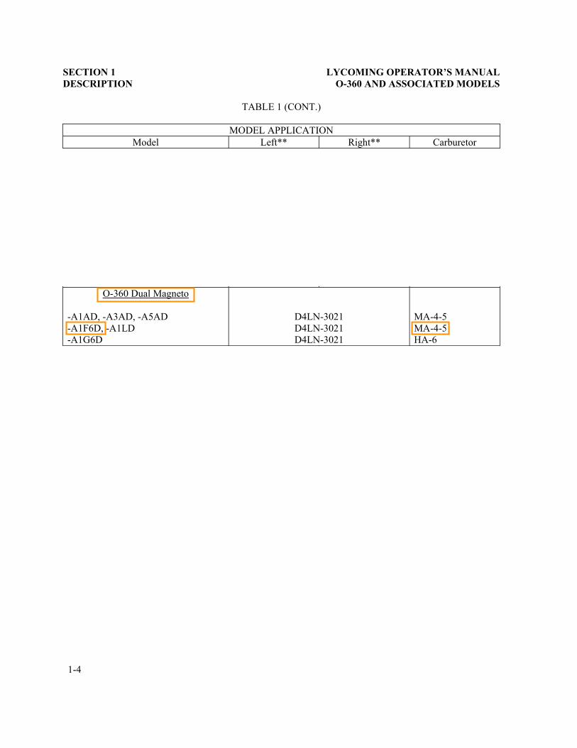
O-360 Dual Magneto
-A1AD, -A3AD, -A5AD-A1F6D, -A1LD-A1G6D
D4LN-3021D4LN-3021D4LN-3021
MA-4-5MA-4-5HA-6
HO-360
-A1A-B1A-B1B-C1A
S4LN-200S4LN-200S4LN-2004347
S4LN-204S4LN-204S4LN-2004370
MA-4-5AAPSH-5BDPSH-5BDHA-6
HIO-360
-A1A, -B1A, -B1B-A1B, -C1A-C1B-D1A-G1A
S4LN-200S4LN-200S4LN-1208S4LN-12084347
S4LN-200S4LN-204S4LN-1209S4LN-12084370
Fuel Injector
RSA-5AB1RSA-5AD1RSA-5AD1RSA-7AA1RSA-5AD1
HIO-360 Dual Magneto
-E1AD-E1BD, -F1AD
D4LN-3021D4LN-3200
RSA-5AB1RSA-5AB1
IO-360
-A1A, -A2A, -B1B, -B1C-A1B, -A2B, -A1B6-A1C, -A2C, -C1B-A1D6, -B1E, -B2E-A3B6
S4LN-200S4LN-1227S4LN-1208S4LN-12274372
S4LN-204S4LN-1209S4LN-1209S4LN-12094370
RSA-5AD1RSA-5AD1RSA-5AD1RSA-5AD1RSA-5AD1
* - Models with counterclockwise rotation employ S4RN series.** - See latest revision of Service Instruction No. 1443 for alternate magnetos.
1-4

/<&20,1*�23(5$725¶6�0$18$/� SECTION 1O-360 AND ASSOCIATED MODELS DESCRIPTION
TABLE 1 (CONT.)
MODEL APPLICATIONModel Left** Right** Fuel Injector
IO-360 (Cont.)
-B1A-B1D, -C1A-B1F, -B2F, -B2F6-B4A, -K2A-C1C, -C1C6, -C1D6-C1E6, -C1F, -F1A-D1A, -E1A-A1D-L2A, -M1B, -B1G6-C1G6
S4LN-200S4LN-200S4LN-1227S4LN-21S4LN-1227S4LN-1227S4LN-1208S4LN-21437143714345
S4LN-204S4LN-204S4LN-1227S4LN-20S4LN-1209S4LN-1209S4LN-1209S4LN-204437143704345
530RSA-5AD1RSA-5AD1RSA-5AD1RSA-5AD1RSA-5AD1RSA-5AD1RSA-5AD1RSA-5AD1RSA-5AD1RSA-5AD1
IO-360 Dual Magneto
-A1B6D, -A3B6D, -J1AD, -J1A6D-A1D6D, -A3D6D
D4LN-3021D4LN-3000
RSA-5AD1RSA-5AD1
AIO-360
-A1A, -A2A-A1B, -A2B, -B1B
S4LN-1208S4LN-1227
S4LN-1209S4LN-1209
RSA-5AD1RSA-5AD1
TIO-360
-A1A, -A1B, -A3B6 S4LN-1208 S4LN-1209 RSA-5AD1TIO-360 Dual Magneto
-C1A6D D4LN-3021 RSA-5AD1
* - Models with counterclockwise rotation employ S4RN series.** - See latest revision of Service Instruction No. 1443 for alternate magnetos.
- For information pertaining to engine model (L)IO-360-M1A, refer to Operation and InstallationManual P/N 60297-36
(QJLQH�PRGHOV�ZLWK� OHWWHU� ³'´�DV��th or 5th character in suffix denotes dual magnetos in single housing.%DVLF� PRGHOV� HPSOR\LQJ� ±��� RU� ±����� �LPSXOVH� Foupling magnetos) use D4LN or D4RN-3021. BasicPRGHOV�HPSOR\LQJ�±����DQG�±������UHWDUG�EUHDNHU�PDJQHWRV��XVH�'�/1�RU�'�51�������([DPSOH�±�%DVLF�model IO-360-C1C uses S4LN-1227 and S4LN-1209, therefore model IO-360-C1CD would employD4LN-3021.
Revised March 2009 1-5
/<&20,1*�23(5$725¶6�0$18$/�
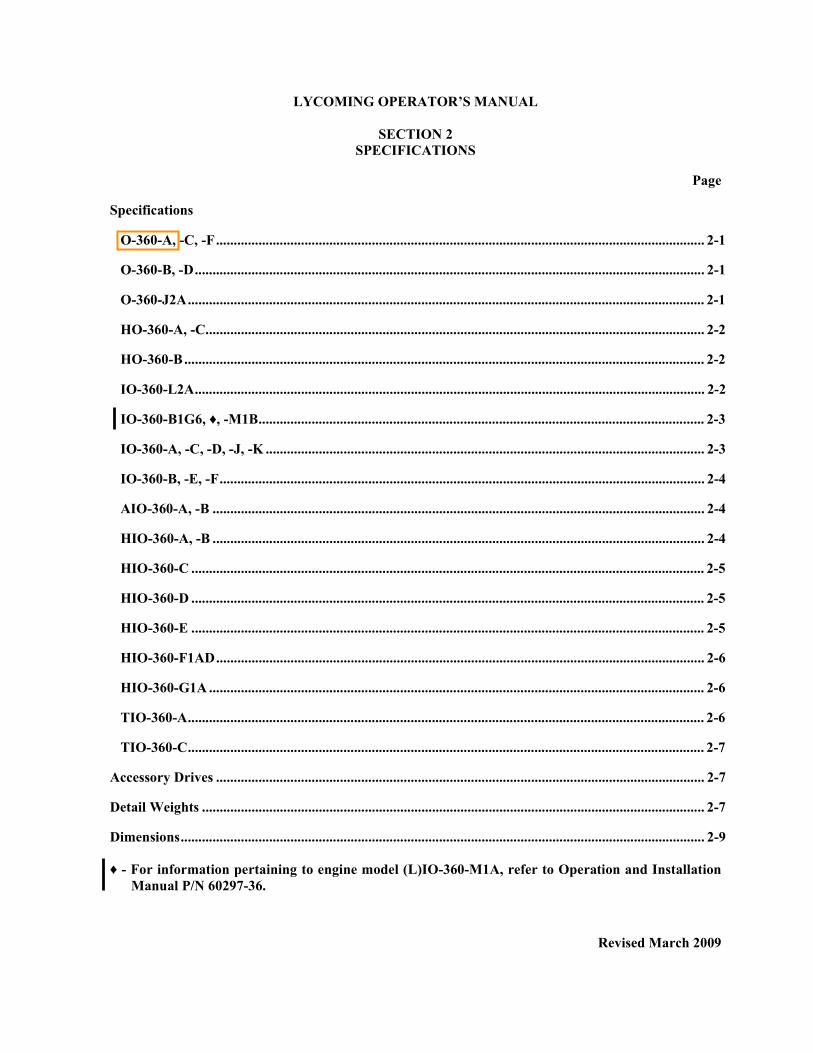
SECTION 2SPECIFICATIONS
Page
Specifications
O-360-A, -C, -F.......................................................................................................................................... 2-1
O-360-B, -D................................................................................................................................................ 2-1
O-360-J2A.................................................................................................................................................. 2-1
HO-360-A, -C............................................................................................................................................. 2-2
HO-360-B................................................................................................................................................... 2-2
IO-360-L2A................................................................................................................................................ 2-2
IO-360-B1G6, , -M1B.............................................................................................................................. 2-3
IO-360-A, -C, -D, -J, -K ............................................................................................................................ 2-3
IO-360-B, -E, -F......................................................................................................................................... 2-4
AIO-360-A, -B ........................................................................................................................................... 2-4
HIO-360-A, -B ........................................................................................................................................... 2-4
HIO-360-C ................................................................................................................................................. 2-5
HIO-360-D ................................................................................................................................................. 2-5
HIO-360-E ................................................................................................................................................. 2-5
HIO-360-F1AD.......................................................................................................................................... 2-6
HIO-360-G1A ............................................................................................................................................ 2-6
TIO-360-A.................................................................................................................................................. 2-6
TIO-360-C.................................................................................................................................................. 2-7
Accessory Drives .......................................................................................................................................... 2-7
Detail Weights .............................................................................................................................................. 2-7
Dimensions.................................................................................................................................................... 2-9
- For information pertaining to engine model (L)IO-360-M1A, refer to Operation and InstallationManual P/N 60297-36.
Revised March 2009
LYCOMING OPERATOR’S MANUAL SECTION 2O-360 AND ASSOCIATED MODELS SPECIFICATIONS
SECTION 2
SPECIFICATIONS
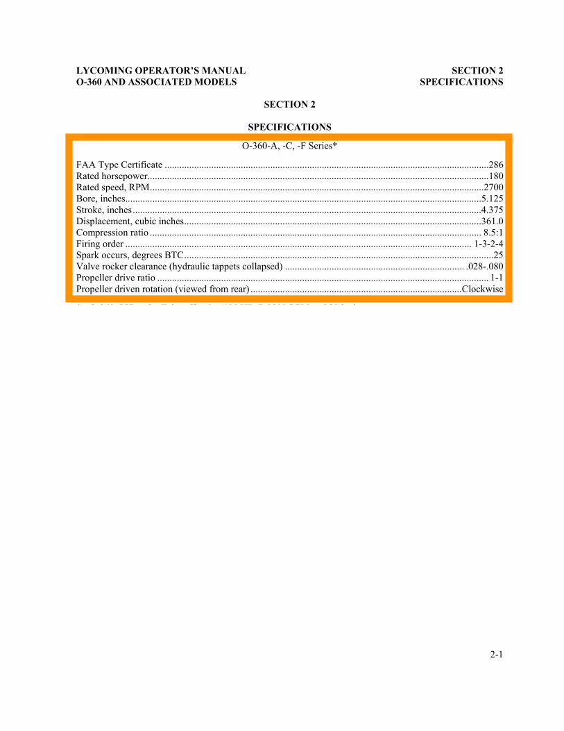
O-360-A, -C, -F Series*
FAA Type Certificate ....................................................................................................................................286Rated horsepower...........................................................................................................................................180Rated speed, RPM........................................................................................................................................2700Bore, inches.................................................................................................................................................5.125Stroke, inches..............................................................................................................................................4.375Displacement, cubic inches.........................................................................................................................361.0Compression ratio ....................................................................................................................................... 8.5:1Firing order ............................................................................................................................................. 1-3-2-4Spark occurs, degrees BTC..............................................................................................................................25Valve rocker clearance (hydraulic tappets collapsed) ......................................................................... .028-.080Propeller drive ratio ....................................................................................................................................... 1-1Propeller driven rotation (viewed from rear) ......................................................................................Clockwise
* - O-360-C2D only. Take-off rating 180 HP @ 2900 RPM and 28 in. hg.
O-360-B, -D Series
FAA Type Certificate ....................................................................................................................................286Rated horsepower...........................................................................................................................................168Rated speed, RPM........................................................................................................................................2700Bore, inches.................................................................................................................................................5.125Stroke, inches..............................................................................................................................................4.375Displacement, cubic inches.........................................................................................................................361.0Compression ratio ....................................................................................................................................... 7.2:1Firing order ............................................................................................................................................. 1-3-2-4Spark occurs, degrees BTC..............................................................................................................................25Valve rocker clearance (hydraulic tappets collapsed) ......................................................................... .028-.080Propeller drive ratio ....................................................................................................................................... 1:1Propeller driven rotation (viewed from rear) ......................................................................................Clockwise
O-360-J2A
FAA Type Certificate ....................................................................................................................................286Rated horsepower...........................................................................................................................................145Rated speed, RPM....................................................................................................................... 2400 thru 2700Bore, inches.................................................................................................................................................5.125Stroke, inches..............................................................................................................................................4.375Displacement, cubic inches.........................................................................................................................361.0Compression ratio ....................................................................................................................................... 8.5:1Firing order ............................................................................................................................................. 1-3-2-4Spark occurs, degrees BTC..............................................................................................................................25Valve rocker clearance (hydraulic tappets collapsed) ......................................................................... .028-.080Propeller drive ratio ....................................................................................................................................... 1:1Propeller driven rotation (viewed from rear) ......................................................................................Clockwise
2-1

LYCOMING OPERATOR’S MANUAL SECTION 2O-360 AND ASSOCIATED MODELS SPECIFICATIONS
TIO-360-C Series
FAA Type Certificate ..............................................................................................................................E16EARated horsepower...........................................................................................................................................210Rated speed, RPM........................................................................................................................................2575Bore, inches.................................................................................................................................................5.125Stroke, inches..............................................................................................................................................4.375Displacement, cubic inches.........................................................................................................................361.0Compression ratio ....................................................................................................................................... 7.3:1Firing order ............................................................................................................................................. 1-3-2-4Spark occurs, degrees BTC..............................................................................................................................20Valve rocker clearance (hydraulic tappets collapsed) ......................................................................... .028-.080Propeller drive ratio ....................................................................................................................................... 1:1Propeller driven rotation (viewed from rear) ......................................................................................Clockwise
*Accessory Drive Drive Ratio **Direction of Rotation
Starter 16.556:1 CounterclockwiseGenerator 1.910:1 ClockwiseGenerator 2.500:1 ClockwiseAlternator*** 3.20:1 ClockwiseTachometer 0.500:1 ClockwiseMagneto 1.000:1 ClockwiseVacuum Pump 1.300:1 CounterclockwisePropeller Governor (Rear Mounted) 0.866:1 ClockwisePropeller Governor (Front Mounted) 0.895:1 ClockwiseFuel Pump AN20010 0.866:1 CounterclockwiseFuel Pump AN20003† 1.000:1 CounterclockwiseFuel Pump – Plunger Operated Dual Drives 0.500:1Vacuum – Hydraulic Pump 1.300:1 CounterclockwiseVacuum – Prop. Governor 1.300:1 Clockwise
* - When applicable.** - Viewed facing drive pad.*** - HIO-360-D1A – Alternator drive is 2.50:1.† - TIO-360-C1A6D, HIO-360-E, -F have clockwise fuel pump drive.
NOTE
Engines with letter “L” in prefix will have opposite rotation to the above.
DETAIL WEIGHTS
1. ENGINE, STANDARD, DRY WEIGHT.
Includes carburetor or fuel injector, magnetos, spark plugs, ignition harness, intercylinder baffles,tachometer drive, starter and generator or alternator drive, starter and generator or alternator with mountingbracket. Turbocharged models include turbocharger, mounting bracket, exhaust manifold, controls, oil linesand baffles.
60297-12-5 - Revised December 2009 2-7
SECTION 2 /<&20,1*�23(5$725¶6�0$18$/�SPECIFICATIONS O-360 AND ASSOCIATED MODELS
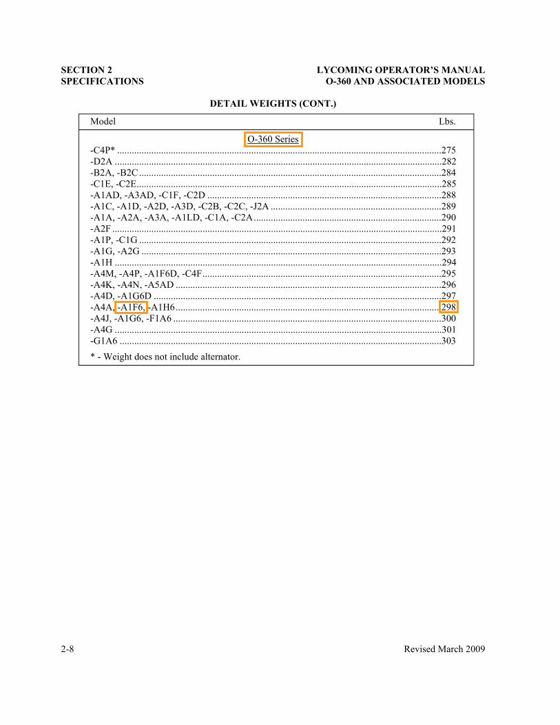
DETAIL WEIGHTS (CONT.)
Model Lbs.
O-360 Series-C4P* .....................................................................................................................................275-D2A ......................................................................................................................................282-B2A, -B2C............................................................................................................................284-C1E, -C2E.............................................................................................................................285-A1AD, -A3AD, -C1F, -C2D ................................................................................................288-A1C, -A1D, -A2D, -A3D, -C2B, -C2C, -J2A ......................................................................289-A1A, -A2A, -A3A, -A1LD, -C1A, -C2A.............................................................................290-A2F .......................................................................................................................................291-A1P, -C1G ............................................................................................................................292-A1G, -A2G ...........................................................................................................................293-A1H ......................................................................................................................................294-A4M, -A4P, -A1F6D, -C4F..................................................................................................295-A4K, -A4N, -A5AD .............................................................................................................296-A4D, -A1G6D ......................................................................................................................297-A4A, -A1F6, -A1H6.............................................................................................................298-A4J, -A1G6, -F1A6 ..............................................................................................................300-A4G ......................................................................................................................................301-G1A6 ....................................................................................................................................303* - Weight does not include alternator.
HO-360 Series-A1A ......................................................................................................................................285-B1A, -B1B, -C1A .................................................................................................................288
IO-360 Series-L2A.......................................................................................................................................278-B1C.......................................................................................................................................289-B1A.......................................................................................................................................295-B1E .......................................................................................................................................296-B1D.......................................................................................................................................297-B1B.......................................................................................................................................299, -M1B..................................................................................................................................300-B1F, -B2F .............................................................................................................................301-B1G6.....................................................................................................................................305-B4A.......................................................................................................................................307-B2F6 .....................................................................................................................................308-K2A ......................................................................................................................................311-A1D6D, -A3D6D, -C1A.......................................................................................................319-C1B.......................................................................................................................................320-C1C, -D1A............................................................................................................................322-J1AD.....................................................................................................................................323- For information pertaining to engine model (L)IO-360-M1A, refer to Operation andInstallation Manual P/N 60297-36.
2-8 Revised March 2009
LYCOMING OPERATOR’S MANUAL SECTION 2O-360 AND ASSOCIATED MODELS SPECIFICATIONS
DETAIL WEIGHTS (CONT.)
Model Lbs.
IO-360 Series (Cont.)
-A1A, -A2A, -C1F, -C1G6 ....................................................................................................324-A1C, -A2A, -A1D ................................................................................................................325-A1B, -A2B............................................................................................................................326-C1D6.....................................................................................................................................328-C1C6.....................................................................................................................................329-A1B6D, -A3B6D, -J1A6D ...................................................................................................330-A1B6, -A3B6........................................................................................................................333-A1D6 ....................................................................................................................................335-C1E6 .....................................................................................................................................337
AIO-360 Series
-A1A, -A2A ...........................................................................................................................331-A1B, -A2B, -B1B .................................................................................................................332
HIO-360 Series
-G1A ......................................................................................................................................283-B1A, -B1B............................................................................................................................290-A1A ......................................................................................................................................311-A1B.......................................................................................................................................312-D1A, -E1AD, -E1BD............................................................................................................321-C1A.......................................................................................................................................322-C1B.......................................................................................................................................323-F1AD ....................................................................................................................................324
TIO-360 Series
-C1A6D..................................................................................................................................379-A1A, -A1B............................................................................................................................386-A3B6.....................................................................................................................................407
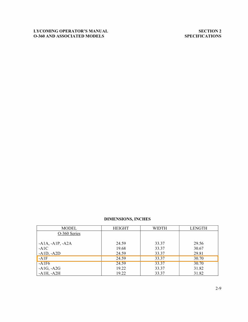
DIMENSIONS, INCHES
MODEL HEIGHT WIDTH LENGTHO-360 Series
-A1A, -A1P, -A2A-A1C-A1D, -A2D-A1F, -A2F-A1F6-A1G, -A2G-A1H, -A2H
24.5919.6824.5924.5924.5919.2219.22
33.3733.3733.3733.3733.3733.3733.37
29.5630.6729.8130.7030.7031.8231.82
2-9
SECTION 2 LYCOMING OPERATOR’S MANUALSPECIFICATIONS O-360 AND ASSOCIATED MODELS
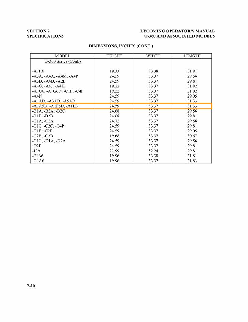
DIMENSIONS, INCHES (CONT.)
MODEL HEIGHT WIDTH LENGTHO-360 Series (Cont.)
-A1H6-A3A, -A4A, -A4M, -A4P-A3D, -A4D, -A2E-A4G, -A4J, -A4K-A1G6, -A1G6D, -C1F, -C4F-A4N-A1AD, -A3AD, -A5AD-A1A5D, -A1F6D, -A1LD-B1A, -B2A, -B2C-B1B, -B2B-C1A, -C2A-C1C, -C2C, -C4P-C1E, -C2E-C2B, -C2D-C1G, -D1A, -D2A-D2B-J2A-F1A6-G1A6
19.3324.5924.5919.2219.2224.5924.5924.5924.6824.6824.7224.5924.5919.6824.5924.5922.9919.9619.96
33.3833.3733.3733.3733.3733.3733.3733.3733.3733.3733.3733.3733.3733.3733.3733.3732.2433.3833.37
31.8129.5629.8131.8231.8229.0531.3331.3329.5629.8129.5629.8129.0530.6729.5629.8129.8131.8131.83
HO-360 Series
-A1A-B1A, -B1B-C1A
24.5919.6819.22
33.3733.3733.37
29.8130.6731.82
IO-360 Series
-A1A, -A2A, -A1D-A1B, -A2B-A1B6, -A3B6-A1C, -A2C-A1D6-A1B6D, -A3B6D, -J1AD-A1D6D, -A3D6D-B1A-B1B, -B1D, -L2A-B1C-B1E-B1F, -B2F, -B2F6-B4A-C1A, -C1B-C1C, -C1C6-C1E6, -C1F
19.3519.3519.3519.3519.3519.3519.3522.4724.8420.7020.7024.8424.8419.4819.4819.48
34.2534.2534.2534.2534.2534.2534.2533.3733.3733.3733.3733.3733.3734.2534.2534.25
29.8130.7030.7029.3030.7031.3331.3332.8129.8130.6832.0930.7029.5631.1433.6533.65
2-10
LYCOMING OPERATOR’S MANUAL
SECTION 3OPERATING INSTRUCTIONS
Page
General.......................................................................................................................................................... 3-1
Prestarting Items of Maintenance .............................................................................................................. 3-1
Starting Procedures ..................................................................................................................................... 3-1
Cold Weather Starting ................................................................................................................................ 3-3
Ground Running and Warm-Up................................................................................................................ 3-3
Ground Check .............................................................................................................................................. 3-4
Operation in Flight ...................................................................................................................................... 3-5
Engine Flight Chart ................................................................................................................................... 3-10
Operating Conditions ................................................................................................................................ 3-11
Shut Down Procedure................................................................................................................................ 3-16
Performance Curves .................................................................................................................................. 3-17
LYCOMING OPERATOR’S MANUAL SECTION 3O-360 AND ASSOCIATED MODELS OPERATING INSTRUCTIONS
SECTION 3
OPERATING INSTRUCTIONS
1. GENERAL. Close adherence to these instructions will greatly contribute to long life, economy andsatisfactory operation of the engine.
NOTE
YOUR ATTENTION IS DIRECTED TO THE WARRANTIES THAT APPEAR IN THEFRONT OF THIS MANUAL REGARDING ENGINE SPEED, THE USE OF SPECIFIEDFUELS AND LUBRICANTS, REPAIR AND ALTERATIONS. PERHAPS NO OTHER ITEMOF ENGINE OPERATION AND MAINTENANCE CONTRIBUTES QUITE SO MUCH TOSATISFACTORY PERFORMANCE AND LONG LIFE AS THE CONSTANT USE OFCORRECT GRADES OF FUEL AND OIL, CORRECT ENGINE TIMING, AND FLYINGTHE AIRCRAFT AT ALL TIMES WITHIN THE SPEED AND POWER RANGE SPECIFIEDFOR THE ENGINE. DO NOT FORGET THAT VIOLATION OF THE OPERATION ANDMAINTENANCE SPECIFICATIONS FOR YOUR ENGINE WILL NOT ONLY VOID YOURWARRANTY BUT WILL SHORTEN THE LIFE OF YOUR ENGINE AFTER ITS WARRANTYPERIOD HAS PASSED.
New engines have been carefully run-in by Lycoming and therefore, no further break-in is necessaryinsofar as operation is concerned; however, new or newly overhauled engines should be operated on straightmineral oil for a minimum of 50 hours or until oil consumption has stabilized. After this period, a change toan approved additive oil may be made, if so desired.
NOTE
Cruising should be done at 65% to 75% power until a total of 50 hours has accumulated oroil consumption has stabilized. This is to ensure proper seating of the rings and is applicableto new engines, and engines in service following cylinder replacement or top overhaul of oneor more cylinders.
The minimum fuel octane rating is listed in the flight chart, Part 8 of this section. Under no circumstancesshould fuel of a lower octane rating or automotive fuel (regardless of octane rating) be used.
2. PRESTARTING ITEMS OF MAINTENANCE. Before starting the aircraft engine for the first flight of theday, there are several items of maintenance inspection that should be performed. These are described inSection 4 under Daily Pre-Flight Inspection. They must be observed before the engine is started.
3. STARTING PROCEDURES. O-360, HO-360, IO-360, AIO-360, HIO-360, TIO-360 Series.
The following starting procedures are recommended, however, the starting characteristics of variousinstallations will necessitate some variation from these procedures.
a. Engines Equipped with Float Type Carburetors.
(1) Perform pre-flight inspection.
3-1
SECTION 3 LYCOMING OPERATOR’S MANUALOPERATING INSTRUCTIONS O-360 AND ASSOCIATED MODELS
����6HW�FDUEXUHWRU�KHDW�FRQWURO�LQ�³RII´�SRVLWLRQ��
����6HW�SURSHOOHU�JRYHUQRU�FRQWURO�LQ�³)XOO�530´�SRVLWLRQ��ZKHUH�DSSOLFDEOH���
����7XUQ�IXHO�YDOYHV�³2Q´��
����0RYH�PL[WXUH�FRQWURO�WR�³)XOO�5LFK´��
(6) Turn on boost pump.
(7) Open throttle approximately ¼ travel.
(8) Prime with 1 to 3 strokes of manual priming pump or activate electric primer for 1 or 2 seconds.
(9) Set magneto selector switch (consult airfUDPH�PDQXIDFWXUHU¶V�KDQGERRN�IRU�FRUUHFW�SRVLWLRQ���
(10) Engage starter.
�����:KHQ�HQJLQH�ILUHV��PRYH�WKH�PDJQHWR�VZLWFK�WR�³%RWK´��
(12) Check oil pressure gage. If minimum oil pressure is not indicated within thirty seconds, stopengine and determine trouble.
b. Engines Equipped with Pressure Carburetors or Bendix Fuel Injectors.
(1) Perform pre-flight inspection.
(2) Set carburetor heat or alternate air control in�³2II´�SRVLWLRQ��
����6HW�SURSHOOHU�JRYHUQRU�FRQWURO�LQ�³)XOO�530´�SRVLWLRQ��ZKHUH�DSSOLFDEOH���
����7XUQ�IXHO�YDOYH�³2Q´��
����7XUQ�ERRVW�SXPS�³2Q´��
(6) Open throttle wide open, move mixture control to ³)XOO�5LFK´�XQWLO�D�VOLJKW�EXW�VWHDG\�IXHO�IORZ�LV�noted (approximately 3 to 5 seconds) then return throWWOH�WR�³&ORVHG´�DQG�UHWXUQ�PL[WXUH�FRQWURO�WR�³,GOH�&XW�2II´��
����7XUQ�ERRVW�SXPS�³2II´��
(8) Open throttle ¼ of travel.
(9) Set magneto selector switch (consult airfUDPH�PDQXIDFWXUHU¶V�KDQGERRN�IRU�FRUUHFW�SRVLWLRQ���
(10) Engage starter.
3-2
LYCOMING OPERATOR’S MANUAL SECTION 3O-360 AND ASSOCIATED MODELS OPERATING INSTRUCTIONS
(11) Move mixture control slowly�DQG�VPRRWKO\�WR�³)XOO�5LFK´��
(12) Check oil pressure gage. If minimum oil pressure is not indicated within thirty seconds, stopengine and determine trouble.
c. Engines Equipped with Simmonds Type 530 Fuel Injector.
(1) Perform pre-flight inspection.
���� 6HW�DOWHUQDWH�DLU�FRQWURO�LQ�³2II´�SRVLWLRQ�
(3) Set propeller governor contURO�LQ�³)XOO�530´�SRVLWLRQ�
���� 7XUQ�IXHO�YDOYH�³2Q´�
���� 7XUQ�ERRVW�SXPS�³2Q´�
(6) Open throttle approximately ¼ travel, move PL[WXUH� FRQWURO� WR� ³)XOO� 5LFK´� XQWLO� D� VOLJKW� EXWsteady fuel flow is noted (approximately 3 to 5 seconds) then retuUQ� WKURWWOH� WR� ³&ORVHG´� DQG�UHWXUQ�PL[WXUH�FRQWURO�WR�³,GOH�&XW�2II´��
���� 7XUQ�ERRVW�SXPS�³2II´��
(8) Open throttle ¼ travel.
���� 0RYH�FRPELQDWLRQ�PDJQHWR�VZLWFK�WR�³6WDUW´��using accelerator pump as a primer while crankingengine.
(10) When engine fires allow thH�VZLWFK�WR�UHWXUQ�WR�³%RWK´��
(11) Check oil pressure gage. If minimum oil pressure is not indicated within thirty seconds, stopengine and determine trouble.
4. COLD WEATHER STARTING. During extreme cold weather, it may be necessary to preheat the engineand oil before starting.
5. GROUND RUNNING AND WARM-UP.
The engines covered in this manual are air-pressure cooled and depend on the forward speed of the aircraftto maintain proper cooling. Particular care is necessary, therefore, when operating these engines on theground. To prevent overheating, it is recommended that the following precautions be observed.
NOTE
Any ground check that requires full throttle operation must be limited to three minutes, orless if the cylinder head temperature should exceed the maximum as stated in this manual.
3-3
SECTION 3 LYCOMING OPERATOR’S MANUALOPERATING INSTRUCTIONS O-360 AND ASSOCIATED MODELS
a. Fixed Wing.
(1) Head the aircraft into the wind.
(2) Leave mixture in “Full Rich”.
(3) Operate only with the propeller in minimum blade angle setting.
(4) Warm-up to approximately 1000-1200 RPM. Avoid prolonged idling and do not exceed 2200RPM on the ground.
(5) Engine is warm enough for take-off when the throttle can be opened without the engine faltering.Take-off with a turbocharged engine must not be started if indicated lubricating oil pressure, dueto cold temperature is above maximum. Excessive oil pressure can cause overboost andconsequent engine damage.
b. Helicopter.
(1) Warm-up at approximately 2000 RPM with rotor engaged as directed in the airframemanufacturer’s handbook.
6. GROUND CHECK.
a. Warm-up as directed above.
b. Check both oil pressure and oil temperature.
c. Leave mixture control in “Full Rich”.
d. Fixed Wing Aircraft (where applicable). Move the propeller control through its complete range tocheck operation and return to full low pitch position. Full feathering check (twin engine) on theground is not recommended but the feathering action can be checked by running the engine between1000-1500 RPM, then momentarily pulling the propeller control into the feathering position. Do notallow the RPM to drop more than 500 RPM.
e. A proper magneto check is important. Additional factors, other than the ignition system, affectmagneto drop-off. They are load-power output, propeller pitch, and mixture strength. The importantpoint is that the engine runs smoothly because magneto drop-off is affected by the variables listedabove. Make the magneto check in accordance with the following procedures.
(1) Fixed Wing Aircraft.
(a) (Controllable pitch propeller). With the propeller in minimum pitch angle, set the engine toproduce 50-65% power as indicated by the manifold pressure gage unless otherwise specifiedin the aircraft manufacturer’s manual. At these settings, the ignition system and spark plugsmust work harder because of the greater pressure within the cylinders. Under these conditions,ignition problems can occur. Magneto checks at low power settings will only indicate fuel/airdistribution quality.
3-4 Revised December 2007
/<&20,1*�23(5$725¶6�0$18$/� SECTION 3O-360 AND ASSOCIATED MODELS OPERATING INSTRUCTIONS
(b) (Fixed pitch propeller). Aircraft that are equipped with fixed pitch propellers, or not equippedwith manifold pressure gage, may check magneto drop-off with engine operating atapproximately 1800 RPM (2000 RPM maximum).
(c) Switch from both magnetos to one and note drop-off; return to both until engine regains speedand switch to the other magneto and note drop-off, then return to both. Drop-off must notexceed 175 RPM and must not exceed 50 RPM between magnetos. Smooth operation of theengine but with a drop-off that exceeds the normal specification of 175 RPM is usually a signof propeller load condition at a rich mixture. Proceed to step e. (1) (d).
(d) If the RPM drop exceeds 175 RPM, slowly lean the mixture until the RPM peaks. Then retardthe throttle to the RPM specified in step e.(1)(a) or e.(1)(b) for the magneto check and repeatthe check. If the drop-off does not exceed 175 RPM, the difference between the magnetos doesnot exceed 50 RPM, and the engine is running smoothly, then the ignition system is operatingproperly. Return the mixture to full rich.
(2) Helicopter.
Raise collective pitch stick to obtain 15 inches manifold pressure at 2000 RPM.
Switch from both magnetos to one and note drop-off; return to both until engine regains speedand switch to the other magneto and note drop-off. Drop-off must not exceed 200 RPM. Drop-offbetween magnetos must not exceed 50 RPM. A smooth drop-off past normal is usually a sign of atoo lean or too rich mixture.
f. Do not operate on a single magneto for too long a period; a few seconds is usually sufficient to checkdrop-off and to minimize plug fouling.
7. OPERATION IN FLIGHT.
a. See airframe manufactureU¶V�LQVWUXFWLRQV�IRU�UHFRPPHQGHG�SRZHU�VHWWLQJV�
b. Throttle movements from full power to idle or from idle to full power are full range movements. Fullrange throttle movements must be performed over a minimum time duration of 2 to 3 seconds.Performing a full range throttle movement at a rate of less than 2 seconds is considered a rapid orinstant movement. Performing rapid movements may result in detuned counterweights which maylead to failure of the counterweight lobes and subsequent engine damage.
c. Fuel Mixture Leaning Procedure.
Improper fuel/air mixture during flight is responsible for engine problems, particularly during take-off and climb power settings. The procedures described in this manual provide proper fuel/air mixturewhen leaning Lycoming engines; they have proven to be both economical and practical by eliminatingexcessive fuel consumption and reducing damaged parts replacement. It is therefore recommendedthat operators of all Lycoming aircraft engines utilize the instructions in this publication any time thefuel/air mixture is adjusted during flight.
Manual leaning may be monitored by exhaust gas temperature indication, fuel flow indication, andby observation of engine speed and/or airspeed. However, whatever instruments are used inmonitoring the mixture, the following general rules must be observed by the operator of Lycomingaircraft engines.
Revised March 2009 3-5
SECTION 3 LYCOMING OPERATOR’S MANUALOPERATING INSTRUCTIONS O-360 AND ASSOCIATED MODELS
GENERAL RULES
Never exceed the maximum red line cylinder head temperature limit.
For maximum service life, cylinder head temperatures should be maintained below 435°F (224°C) duringhigh performance cruise operation and below 400°F (205°C) for economy cruise powers.
Do not manually lean engines equipped with automatically controlled fuel system.
On engines with manual mixture control, maintain mixture control in “Full Rich” position for rated take-off, climb, and maximum cruise powers (above approximately 75%). However, during take-off from highelevation airport or during climb, roughness or loss of power may result from over-richness. In such a caseadjust mixture control only enough to obtain smooth operation – not for economy. Observe instruments fortemperature rise. Rough operation due to over-rich fuel/air mixture is most likely to be encountered incarbureted engines at altitude above 5,000 feet.
Always return the mixture to full rich before increasing power settings.
Operate the engine at maximum power mixture for performance cruise powers and at best economymixture for economy cruise power; unless otherwise specified in the airplane owner’s manual.
During letdown flight operations it may be necessary to manually lean uncompensated carbureted or fuelinjected engines to obtain smooth operation.
On turbocharged engines never exceed 1650°F turbine inlet temperature (TIT).
1. LEANING TO EXHAUST GAS TEMPERATURE GAGE.
a. Normally aspirated engines with fuel injectors or uncompensated carburetors.
(1) Maximum Power Cruise (approximately 75% power) – Never lean beyond 150°F on rich side ofSHDN� (*7� XQOHVV� DLUFUDIW� RSHUDWRU¶V� PDQXDl shows otherwise. Monitor cylinder headtemperatures.
(2) Best Economy Cruise (approximately 75% power and below) – Operate at peak EGT.
b. Turbocharged engines.
(1) Best Economy Cruise – Lean to peak turbine inlet temperature (TIT) or 1650°F, whicheveroccurs first.
(2) Maximum Power Cruise – The engine must always be operated on the rich side of peak EGT orTIT. Before leaning to obtain maximum power mixture it is necessary to establish a referencepoint. This is accomplished as follows:
(a) Establish a peak EGT or TIT for best economy operation at the highest economy cruisepower without exceeding 1650°F.
3-6
LYCOMING OPERATOR’S MANUAL SECTION 3O-360 AND ASSOCIATED MODELS OPERATING INSTRUCTIONS
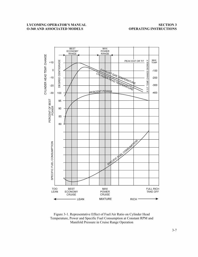
Figure 3-1. Representative Effect of Fuel/Air Ratio on Cylinder HeadTemperature, Power and Specific Fuel Consumption at Constant RPM and
Manifold Pressure in Cruise Range Operation
3-7
SECTION 3 LYCOMING OPERATOR’S MANUALOPERATING INSTRUCTIONS O-360 AND ASSOCIATED MODELS
(b) Deduct 125°F from this temperature and thus establish the temperature reference point for usewhen operating at maximum power mixture.
(c) Return mixture control to full rich and adjust the RPM and manifold pressure for desiredperformance cruise operation.
(d) Lean out mixture until EGT or TIT is the value established in step (b). This sets the mixtureat best power.
2. LEANING TO FLOWMETER.
Lean to applicable fuel-flow tables or lean to indicator marked for correct fuel flow for each powersetting.
3. LEANING WITH MANUAL MIXTURE CONTROL. (Economy cruise, 75% power or less, withoutflowmeter or EGT gauge.)
a. Carbureted Engines.
(1) Slowly move mixture control from “Full Rich” position toward lean position.
(2) Continue leaning until engine roughness is noted.
(3) Enrich until engine runs smoothly and power is regained.
b. Fuel Injected Engines.
(1) Slowly move mixture control from “Full Rich” position toward lean position.
(2) Continue leaning until slight loss of power is noted (loss of power may or may not beaccompanied by roughness.
(3) Enrich until engine runs smoothly and power is regained.
WARNING
REFER TO THE PILOT’S OPERATING HANDBOOK OR AIRFRAMEMANUFACTURER’S MANUAL FOR ADDITIONAL INSTRUCTIONS ON THE USE OFCARBURETOR HEAT CONTROL. INSTRUCTIONS FOUND IN EITHER PUBLICATIONSUPERSEDE THE FOLLOWING INFORMATION.
c. Use of Carburetor Heat Control – Under certain moist atmospheric conditions (generally at a relativehumidity of 50% or greater) and at temperatures of 20° to 90°F it is possible for ice to form in theinduction system. Even in summer weather ice may form. This is due to the high air velocity throughthe carburetor venturi and the absorption of heat from this air by vaporization of the fuel. Thetemperature in the mixture chamber may drop as much as 70°F below the temperature of theincoming air. If this air contains a large amount of moisture, the cooling process can causeprecipitation in the form of ice. Ice formation generally begins in the vicinity of the butterfly andmay build up to such an extent that a drop in power output could result. In installations equippedwith fixed pitch propellers, a loss of power is reflected by a drop in manifold pressure and RPM. Ininstallations equipped with constant speed propellers, a loss of power is reflected by a drop inmanifold pressure. If not corrected, this condition may cause complete engine stoppage.
3-8 Revised September 2007
LYCOMING OPERATOR’S MANUAL SECTION 3O-360 AND ASSOCIATED MODELS OPERATING INSTRUCTIONS
To avoid this, all installations are equipped with a system for preheating the incoming air supply tothe carburetor. In this way sufficient heat is added to replace the heat loss of vaporization of fuel, andthe mixing chamber temperature cannot drop to the freezing point of water (32°F). The air preheater isa tube or jacket through which the exhaust pipe from one or more cylinders is passed, and the airflowing over these surfaces is raised to the required temperature before entering the carburetor.Consistently high temperatures are to be avoided because of a loss in power and a decided variation ofmixture. High charge temperatures also favor detonation and preignition, both of which are to beavoided if normal service life is to be expected from the engine. The following outline is the propermethod of utilizing the carburetor heat control.
(1) Ground Operation – Use of the carburetor air heat on the ground must be held to an absoluteminimum. On some installations the air does not pass through the air filter, and dirt and foreignsubstances can be taken into the engine with the resultant cylinder and piston ring wear. Only usecarburetor air heat on the ground to make certain it is functioning properly.
(2) Take-Off – Set the carburetor heat in full cold position. For take-off and full throttle operation thepossibility of expansion or throttle icing at wide throttle openings is very remote.
(3) Climbing –When climbing at part throttle power settings of 80% or above, set the carburetor heatcontrol in the full cold position; however, if it is necessary to use carburetor heat to prevent icingit is possible for engine roughness to occur due to the over-rich fuel/air mixture produced by theadditional carburetor heat. When this happens, lean the mixture with the mixture control onlyenough to produce smooth engine operation. Do not continue to use carburetor heat after flight isout of icing conditions, and return mixture to full rich when carburetor heat is removed.
(4) Flight Operation – During normal flight, leave the carburetor air heat control in the full coldposition. On damp, cloudy, foggy or hazy days, regardless of the outside air temperature, be alertfor loss of power. This will be evidenced by an unaccountable loss in manifold pressure or RPMor both, depending on whether a constant speed or fixed pitch propeller is installed on theaircraft. If this happens, apply full carburetor air heat and open the throttle to limiting manifoldpressure and RPM. This will result in a slight additional drop in manifold pressure, which isnormal, and this drop will be regained as the ice is melted out of the induction system. When icehas been melted from the induction system, return the carburetor heat control to the full coldposition. In those aircraft equipped with a carburetor air temperature gauge, partial heat may beused to keep the mixture temperature above the freezing point of water (32°F).
WARNING
CAUTION MUST BE EXERCISED WHEN OPERATING WITH PARTIAL HEAT ONAIRCRAFT THAT DO NOT HAVE A CARBURETOR AIR TEMPERATURE GAUGE. USEEITHER FULL HEAT OR NO HEAT IN AIRCRAFT THAT ARE NOT EQUIPPED WITH ACARBURETOR AIR TEMPERATURE GAUGE.
(5) Landing Approach – In making a landing approach, the carburetor heat is generally in the “FullCold” position. However, if icing conditions are suspected, apply “Full Heat”. In the case thatfull power needs to be applied under these conditions, as for an aborted landing, return thecarburetor heat to “Full Cold” after full power application.
Revised September 2007 3-9
SECTION 3 LYCOMING OPERATOR’S MANUALOPERATING INSTRUCTIONS O-360 AND ASSOCIATED MODELS
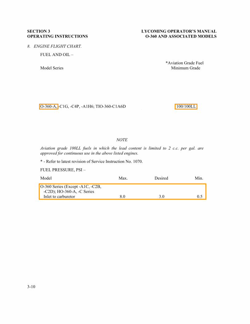
8. ENGINE FLIGHT CHART.
)8(/�$1'�2,/�±�
*Aviation Grade FuelModel Series Minimum Grade
O-360-B, -D 80/87O-360-A1P, -C1F, -C4F; HO-360-C1A 91/96O-360-C, -F; HO-360-A, -B; IO-360-B, -E; HIO-360-B 91/96 or 100/130O-360-J2A 91/96 or 100/100LLIO-360-L2A, -M1A, -M1B 91/96 or 100LLHIO-360-G1A 91/96 or 100LLO-360-A, -C1G, -C4P, -A1H6; TIO-360-C1A6D 100/100LLIO-360-B1G6, -C1G6, -J, -K2A, -A1D6D, -A3B6, -A3D6D;HIO-360-A1B 100/100LLAIO-360-A, -B; IO-360-A, -C, -D, -F 100/130HIO-360-A, -C, -D, -E, -F 100/130TIO-360-A 100/130
NOTE
Aviation grade 100LL fuels in which the lead content is limited to 2 c.c. per gal. areapproved for continuous use in the above listed engines.
* - Refer to latest revision of Service Instruction No. 1070.
)8(/�35(6685(��36,�±�
Model Max. Desired Min.
O-360 Series (Except -A1C, -C2B,-C2D); HO-360-A, -C SeriesInlet to carburetor 8.0 3.0 0.5O-360-A1C, -C2B, -C1D;HO-360-B SeriesInlet to carburetor 18 13 9.0HIO-360-A1BInlet to fuel pump 30 ----- -2IO-360 Series (Except -B1A, -F1A);AIO-360 Series, HIO-360 Series(Except -A1B)Inlet to fuel pump 35 ----- -2IO-360-F1AInlet to fuel pump 35 ----- -2IO-360 Series (Except -B1A),AIO-360 Series; HIO-360 SeriesInlet to fuel injector 45 14IO-360-B1AInlet to fuel injector 2 -2
3-10
LYCOMING OPERATOR’S MANUAL SECTION 3O-360 AND ASSOCIATED MODELS OPERATING INSTRUCTIONS
FUEL PRESSURE, PSI (CONT.) –
Model Max. Desired Max.
HIO-360-E, -F SeriesInlet to fuel pump 55 -2Inlet to fuel injector 55 27TIO-360-A SeriesInlet to fuel pump 50 -2Inlet to fuel injector 45 20TIO-360-C1A6DInlet to fuel pump 65 -2Inlet to fuel injector 65 22
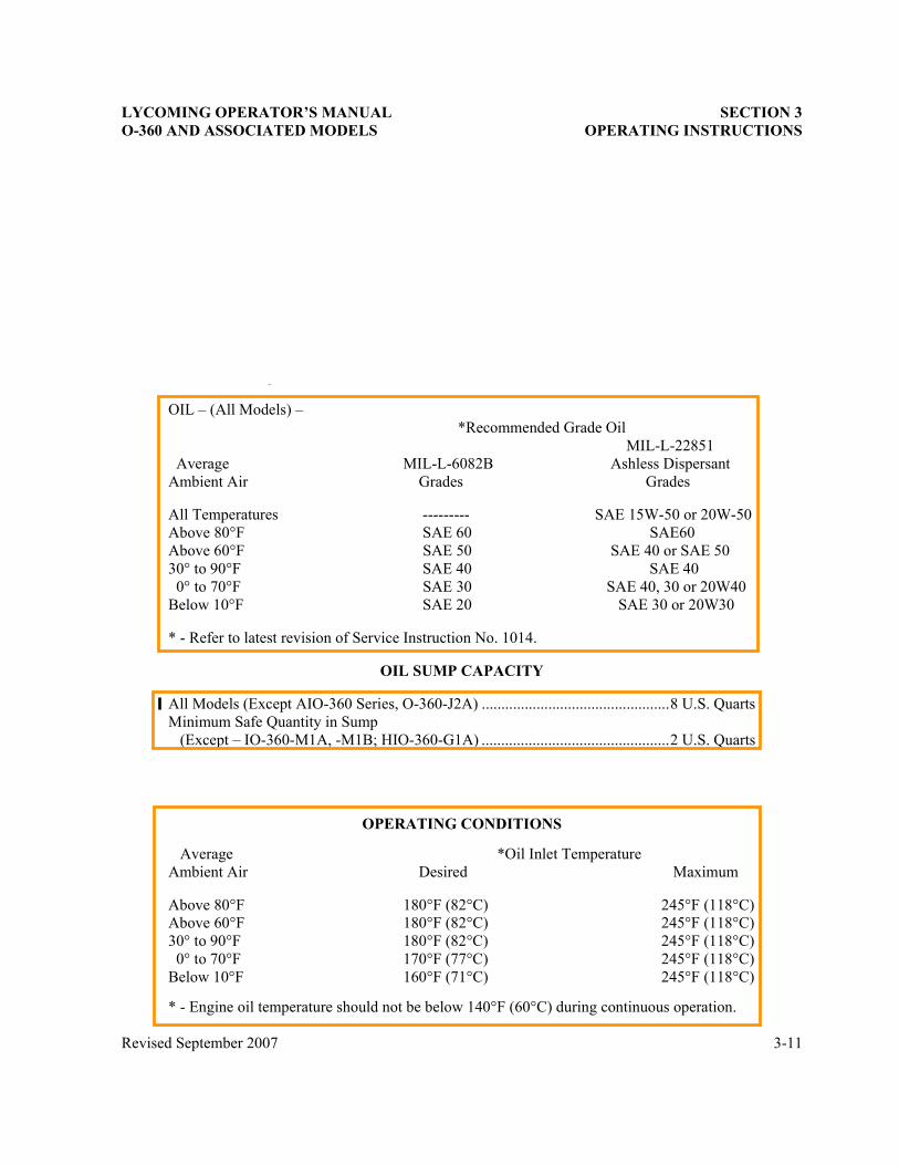
OIL – (All Models) –*Recommended Grade Oil
MIL-L-22851Average MIL-L-6082B Ashless DispersantAmbient Air Grades Grades
All Temperatures --------- SAE 15W-50 or 20W-50Above 80°F SAE 60 SAE60Above 60°F SAE 50 SAE 40 or SAE 5030° to 90°F SAE 40 SAE 400° to 70°F SAE 30 SAE 40, 30 or 20W40Below 10°F SAE 20 SAE 30 or 20W30
* - Refer to latest revision of Service Instruction No. 1014.
OIL SUMP CAPACITY
All Models (Except AIO-360 Series, O-360-J2A) ................................................8 U.S. QuartsMinimum Safe Quantity in Sump(Except – IO-360-M1A, -M1B; HIO-360-G1A) ................................................2 U.S. QuartsIO-360-M1A, -M1B; HIO-360-G1A..................................................................4 U.S. QuartsAIO-360 Series ...........................................................................................................Dry SumpO-360-J2A..............................................................................................................6 U.S. Quarts
OPERATING CONDITIONS
Average *Oil Inlet TemperatureAmbient Air Desired Maximum
Above 80°F 180°F (82°C) 245°F (118°C)Above 60°F 180°F (82°C) 245°F (118°C)30° to 90°F 180°F (82°C) 245°F (118°C)0° to 70°F 170°F (77°C) 245°F (118°C)Below 10°F 160°F (71°C) 245°F (118°C)
* - Engine oil temperature should not be below 140°F (60°C) during continuous operation.
Revised September 2007 3-11
SECTION 3 LYCOMING OPERATOR’S MANUALOPERATING INSTRUCTIONS O-360 AND ASSOCIATED MODELS
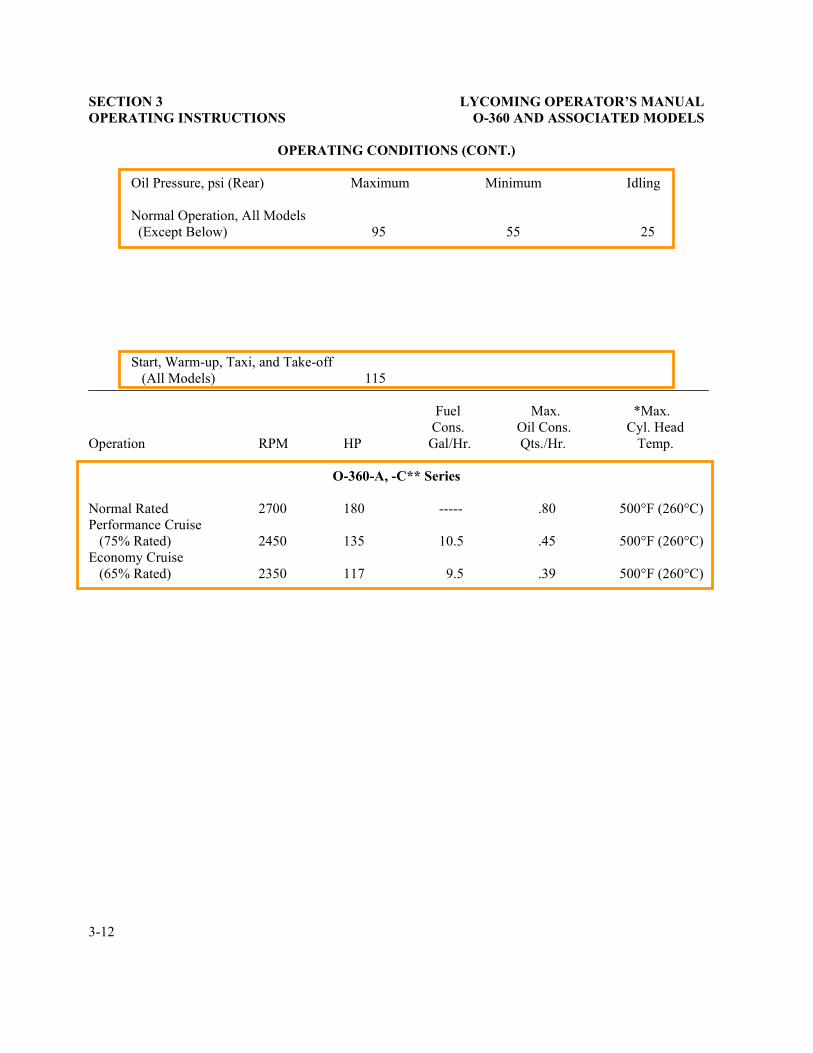
OPERATING CONDITIONS (CONT.)
Oil Pressure, psi (Rear) Maximum Minimum Idling
Normal Operation, All Models(Except Below) 95 55 25
TIO-360-C1A6D 95 50 25
Oil Pressure, psi (Front)
O-360-A4N, -F1A6 90 50 20
Start, Warm-up, Taxi, and Take-off(All Models) 115
Fuel Max. *Max.Cons. Oil Cons. Cyl. Head
Operation RPM HP Gal/Hr. Qts./Hr. Temp.
O-360-A, -C** Series
Normal Rated 2700 180 ----- .80 500°F (260°C)Performance Cruise(75% Rated) 2450 135 10.5 .45 500°F (260°C)Economy Cruise(65% Rated) 2350 117 9.5 .39 500°F (260°C)
O-360-B, -D Series
Normal Rated 2700 168 ----- .75 500°F (260°C)Performance Cruise(75% Rated) 2450 126 11.6 .42 500°F (260°C)Economy Cruise(65% Rated) 2350 109 9.0 .37 500°F (260°C)
O-360-A1P, -A4D, -A4P, -C4P, -F, -G Series
Normal Rated 2700 180 ----- .80 500°F (260°C)Performance Cruise(75% Rated) 2450 135 9.7 .45 500°F (260°C)Economy Cruise(65% Rated) 2350 117 8.3 .39 500°F (260°C)
� � � ��$W�%D\RQHW�/RFDWLRQ�±�)RU�PD[LPXP�VHUYLFH� OLIH�of the engine maintain cylinder head temperaturebetween 150°F and 400°F during continuous operation.
���2�����&�'�2QO\�±�7DNH�RII�UDWLQJ�����+3�DW������530�����LQ��+J��
3-12
SECTION 3 LYCOMING OPERATOR’S MANUALOPERATING INSTRUCTIONS O-360 AND ASSOCIATED MODELS
9. SHUT DOWN PROCEDURE.
a. Fixed Wing.
(1) Set propeller governor control for minimum blade angle when applicable.
(2) Idle until there is a decided drop in cylinder head temperature.
���� 0RYH�PL[WXUH�FRQWURO�WR�³,GOH�&XW�2II´��
(4) When engine stops, turn off switches.
b. Helicopters.
(1) Idle as directed in the airframe manufacturer¶V�KDQGERRN��XQWLO�WKHUH�LV�D�GHFLGHG�GURS�LQ�F\OLQGHU�head temperature.
���� 0RYH�PL[WXUH�FRQWURO�WR�³,GOH�&XW�2II´��
(3) When engine stops, turn off switches.
3-16
SECTION 3 LYCOMING OPERATOR’S MANUALOPERATING INSTRUCTIONS O-360 AND ASSOCIATED MODELS
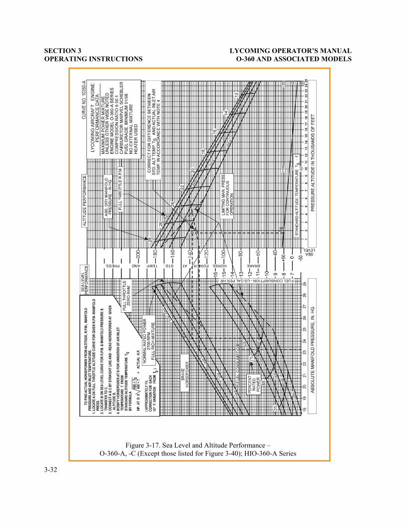
)LJXUH�������6HD�/HYHO�DQG�$OWLWXGH�3HUIRUPDQFH�±�O-360-A, -C (Except those listed for Figure 3-40); HIO-360-A Series
3-32
LYCOMING OPERATOR’S MANUAL SECTION 3O-360 AND ASSOCIATED MODELS OPERATING INSTRUCTIONS
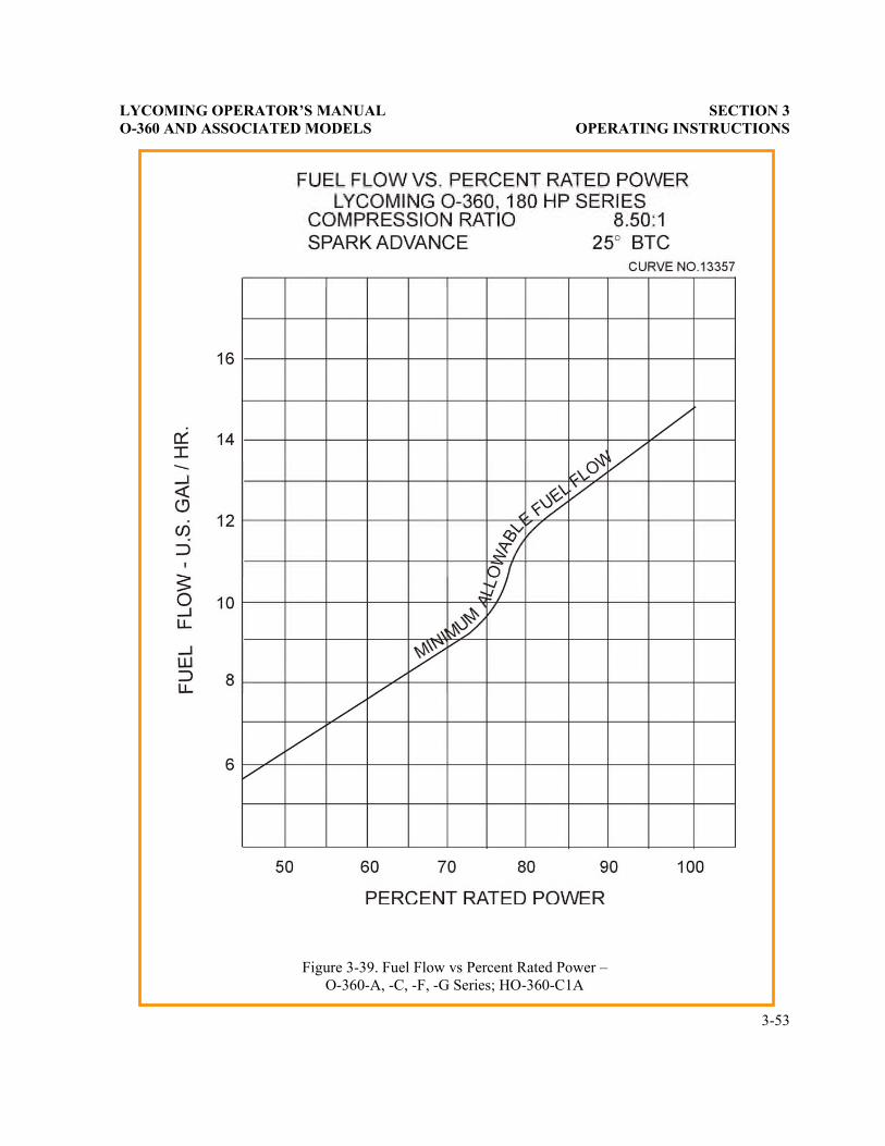
)LJXUH�������)XHO�)ORZ�YV�3HUFHQW�5DWHG�3RZHU�±�O-360-A, -C, -F, -G Series; HO-360-C1A
3-53
LYCOMING OPERATOR’S MANUAL
SECTION 4PERIODIC INSPECTIONS
Page
General.......................................................................................................................................................... 4-1
Pre-Starting Inspection ............................................................................................................................... 4-1
Daily Pre-Flight – Engine............................................................................................................................ 4-2
Daily Pre-Flight – Turbocharger................................................................................................................ 4-2
25-Hour Inspection ...................................................................................................................................... 4-2
50-Hour Inspection ...................................................................................................................................... 4-2
100-Hour Inspection .................................................................................................................................... 4-4
400-Hour Inspection .................................................................................................................................... 4-5
Non-Scheduled Inspections ......................................................................................................................... 4-5
LYCOMING OPERATOR’S MANUAL SECTION 4O-360 AND ASSOCIATED MODELS PERIODIC INSPECTIONS
SECTION 4
PERIODIC INSPECTIONS
NOTE
Perhaps no other factor is quite so important to safety and durability of the aircraft and itscomponents are faithful and diligent attention to regular checks for minor troubles andprompt repair when they are found.
The operator should bear in mind that the items listed in the following pages do not constitute a completeaircraft inspection, but are meant for the engine RQO\��&RQVXOW� WKH� DLUIUDPH�PDQXIDFWXUHU¶V� KDQGERRN� IRU�additional instructions.
Pre-Starting Items of Maintenance – The daily pre-flight inspection is a check of the aircraft prior to thefirst flight of the day. The inspection is to determine the general condition of the aircraft and engine.
The importance of proper pre-flight inspection cannot be over emphasized. Statistics prove severalhundred accidents occur yearly directly responsible to poor pre-flight.
Among the major causes of poor pre-flight inspection are lack of concentration, reluctance toacknowledge the need for a check list, carelessness bred by familiarity and haste.
4-1
SECTION 4 LYCOMING OPERATOR’S MANUALPERIODIC INSPECTIONS O-360 AND ASSOCIATED MODELS
1. DAILY PRE-FLIGHT.
a. Engine.
���� %H�VXUH�DOO�VZLWFKHV�DUH�LQ�WKH�³2II´�SRVLWLRQ��
(2) Be sure magneto ground wires are connected.
(3) Check oil level.
(4) See that fuel tanks are full.
(5) Check fuel and oil line connections; note minor indications for repair at 50-hour inspection.Repair any leaks before aircraft is flown.
(6) Open the fuel drain to remove any accumulation of water and sediment.
(7) Make sure all shields and cowling are in place and secure. If any are missing or damaged, repairor replacement should be made before the aircraft is flown.
(8) Check controls for general condition, travel, and freedom of movement.
(9) Induction system air filter should be inspected and serviced in accordance with the airframePDQXIDFWXUHU¶V�UHFRPPHQGDWLRQV��
b. Turbocharger.
(1) Inspect mounting and connections of turbocharger for security, lubricant or air leakage.
(2) Check engine crankcase breather for restrictions to breather.
2. 25-HOUR INSPECTION (ENGINE). After the first twenty-five hours operation time; new, rebuilt ornewly overhauled engines should undergo a 50-hour inspection including draining and renewing lubricatingoil. If engine has no full-flow oil filter, change oil every 25 hours. Also, inspect and clean suction andpressure screens.
3. 50-HOUR INSPECTION (ENGINE). In addition to the items listed for daily pre-flight inspection, thefollowing maintenance checks should be made after every 50 hours of operation.
a. Ignition System.
(1) If fouling of spark plugs is apparent, rotate bottom plugs to upper position.
(2) Examine spark plug leads of cable and ceramics for corrosion deposits. This condition isevidence of either leaking spark plugs, improper cleaning of the spark plug walls or connectorends. Where this condition is found, clean the cable ends, spark plug walls and ceramics with adry, clean cloth or a clean cloth moistened with methyl-ethyl-ketone. All parts should be cleanand dry before reassembly.
4-2

LYCOMING OPERATOR’S MANUAL SECTION 4O-360 AND ASSOCIATED MODELS PERIODIC INSPECTIONS
(3) Check ignition harness for security of mounting clamps and be sure connections are tight at sparkplug and magneto terminals.
b. Fuel and Induction System – Check the primer lines for leaks and security of the clamps. Remove andclean the fuel inlet strainers. Check the mixture control and throttle linkage for travel, freedom ofmovement, security of the clamps and lubricate if necessary. Check the air intake ducts for leaks,security, filter damage; evidence of dust or other solid material in the ducts is indicative of inadequatefilter care or damaged filter. Check vent lines for evidence of fuel or oil seepage; if present, fuel pumpmay require replacement.
c. Lubrication System.
(1) Replace external full flow oil filter element. (Check used element for metal particles.) Drain andrenew lubricating oil.
(2) (Engines Not Equipped with External Filter.) Remove oil pressure screen and clean thoroughly.Note carefully for presence of metal particles that are indicative of internal engine damage.Change oil every 25 hours.
(3) Check oil lines for leaks, particularly at connections for security of anchorage and for wear due torubbing or vibration, for dents and cracks.
d. Exhaust System – Check attaching flanges at exhaust ports on cylinder for evidence of leakage. If theyare loose, they must be removed and machined flat before they are reassembled and tightened.Examine exhaust manifolds for general condition.
e. Cooling System – Check cowling and baffle for damage and secure anchorage. Any damaged ormissing part of the cooling system must be repaired or replaced before the aircraft resumes operation.
f. Cylinders – Check rocker box cover for evidence of oil leaks. If found, replace gasket and tightenscrews to specified torque (50 in.-lbs.).
Check cylinders for evidence of excessive heat which is indicated by burned paint on the cylinder.This condition is indicative of internal damage to the cylinder and, if found, its cause must bedetermined and corrected before the aircraft resumes operation.
Heavy discoloration and appearance of seepage at cylinder head and barrel attachment area isusually due to emission of thread lubricant used during assembly of the barrel at the factory, or byslight gas leakage which stops after the cylinder has been in service for awhile. This condition isneither harmful nor detrimental to engine performance and operation. If it can be proven that leakageexceeds these conditions, the cylinder should be replaced.
g. Turbocharger – All fluid power lines and mounting brackets incorporated in turbocharger systemshould be checked for leaks, tightness and any damage that may cause a restriction.
Check for accumulation of dirt or other interference with the linkage between the bypass valve andthe actuator which may impair operation of turbocharger. Clean or correct cause of interference.
4-3
SECTION 4 LYCOMING OPERATOR’S MANUALPERIODIC INSPECTION O-360 AND ASSOCIATED MODELS
The vent line from the actuator should be checked for oil leakage. Any constant oil leakage is causefor replacement of piston seal.
Check alternate air valve to be sure it swings free and seals tightly.
h. Carburetor – Check throttle body attaching screws for tightness. The correct torque for these screwsis 40-50 in.-lbs.
4. 100-HOUR INSPECTION. In addition to the items listed for daily pre-flight and 50-hour inspection, thefollowing maintenance checks should be made after every one hundred hours of operation.
a. Electrical System.
(1) Check all wiring connected to the engine or accessories. Any shielded cables that are damagedshould be replaced. Replace clamps or loose wires and check terminals for security andcleanliness.
(2) Remove spark plugs; test, clean and regap. Replace if necessary.
b. Lubrication System – Drain and renew lubricating oil.
c. Magnetos – Check breaker points for pitting and minimum gap. Check for excessive oil in the breakercompartment, if found, wipe dry with a clean lintless cloth. The felt located at the breaker pointsshould be lubricated in accordance with the magneWR�PDQXIDFWXUHU¶V� LQVWUXFWions. Check magneto toengine timing. Timing procedure is described in Section 5, 1, b of this manual.
d. Engine Accessories – Engine mounted accessories such as pumps, temperature and pressure sensingunits should be checked for secure mounting, tight connections.
e. Cylinders – Check cylinders visually for cracked or broken fins.
f. Engine Mounts – Check engine mounting bolts and bushings for security and excessive wear. Replaceany bushings that are excessively worn.
g. Fuel Injection Nozzles and Fuel Lines – Check fuel injector nozzles for looseness, tighten to 60 in.-lbs. torque. Check fuel line for dye stains at connection indicating leakage and security of line. Repairor replacement must be accomplished before the aircraft resumes operation.
h. Turbocharger – Inspect all air ducting and connections in turbocharger system for leaks. Makeinspection both with engine shut down and with engine running. Check at manifold connections toturbine inlet and at engine exhaust manifold gasket, for possible exhaust gas leakage.
CAUTION
DO NOT OPERATE THE TURBOCHARGER IF LEAKS EXIST IN THE DUCTING, OR IFAIR CLEANER IS NOT FILTERING EFFICIENTLY. DUST LEAKING INTO AIR DUCTINGCAN DAMAGE TURBOCHARGER AND ENGINE.
Check for dirt or dust build-up within the turbocharger. Check for uneven deposits on the impeller.Consult AiResearch Div. Manual TP-21 for method to remove all such foreign matter.
4-4
LYCOMING OPERATOR’S MANUAL SECTION 4O-360 AND ASSOCIATED MODELS PERIODIC INSPECTIONS
5. 400-HOUR INSPECTION. In addition to the items listed for daily pre-flight, 50-hour and 100-hourinspection, the following maintenance check should be made after every 400 hours of operation.
Valve Inspection – Remove rocker box covers and check for freedom of valve rockers when valves areclosed. Look for evidence of abnormal wear or broken parts in the area of the valve tips, valve keeper,springs and spring seats. If any indications are found, the cylinder and all of its components should beremoved (including the piston and connecting rod assembly) and inspected for further damage. Replace anyparts that do not conform with limits shown in the latest revision of Special Service Publication No.SSP1776.
6. NON-SCHEDULED INSPECTIONS. Occasionally, Service Bulletins or Service Instructions are issuedby Lycoming that require inspection procedures that are not listed in this manual. Such publications usuallyare limited to specified engine models and become obsolete after corrective modification has beenaccomplished. All such publications are available from Lycoming distributors, or from the factory bysubscription. Consult the latest revision of Service Letter No. L114 for subscription information.Maintenance facilities should have an up-to-date file of these publications available at all times.
4-5
LYCOMING OPERATOR’S MANUAL
SECTION 5MAINTENANCE PROCEDURES
Page
General.......................................................................................................................................................... 5-1
Ignition and Electrical System
Ignition Harness and Wire Replacement................................................................................................ 5-1
Timing Magneto to Engine
Single Magneto ....................................................................................................................................... 5-1
Dual Magneto ......................................................................................................................................... 5-1
Generator or Alternator Output ............................................................................................................. 5-4
Fuel System
Repair of Fuel Leaks................................................................................................................................. 5-4
Carburetor or Fuel Injector Inlet Screen Assembly.............................................................................. 5-4
Fuel Grades and Limitations ................................................................................................................... 5-4
Air Intake Ducts and Filter...................................................................................................................... 5-4
Idle Speed and Mixture Adjustment ....................................................................................................... 5-4
Lubrication System
Oil Grades and Limitations...................................................................................................................... 5-4
Oil Suction and Oil Pressure Screens ..................................................................................................... 5-5
Oil Pressure Relief Valve.......................................................................................................................... 5-5
Cylinders....................................................................................................................................................... 5-5
Generator or Alternator Drive Belt Tension............................................................................................. 5-9
Turbocharger Controls ............................................................................................................................... 5-9
LYCOMING OPERATOR’S MANUAL SECTION 5O-360 AND ASSOCIATED MODELS MAINTENANCE PROCEDURES
SECTION 5
MAINTENANCE PROCEDURES
The procedures described in this section are provided to guide and instruct personnel in performing suchmaintenance operations that may be required in conjunction with the periodic inspections listed in thepreceding section. No attempt is made to include repair and replacement operations that will be found in theapplicable Lycoming Overhaul Manual.
1. IGNITION AND ELECTRICAL SYSTEM.
a. Ignition Harness and Wire Replacement – In the event that an ignition harness or an individual lead isto be replaced, consult the wiring diagram to be sure harness is correctly installed. Mark location ofclamps and clips to be certain the replacement is clamped at correct locations.
b. Timing Magnetos to Engine.
(1) Remove a spark plug from No. 1 cylinder and place a thumb over the spark plug hole. Rotate thecrankshaft in direction of normal rotation until the compression stroke is reached, this is indicatedby a positive pressure inside the cylinder tending to push the thumb off the spark plug hole.Continue rotating the crankshaft until the advance timing mark on the front face of the starter ringgear is in alignment with the smDOO�KROH�ORFDWHG�DW�WKH�WZR�R¶FORFk position on the front face ofthe starter housing. (Ring gear may be marked at 20° and 25°. Consult specifications for correcttiming mark of your installation.) At this point, the engine is ready for assembly of the magnetos.
(2) Single Magneto – Remove the inspection plugs from both magnetos and turn the drive shaft indirection of normal rotation until (-20 and -200 series) the first painted chamfered tooth on thedistributor gear is aligned in the center of the inspection window; (-1200 series) the applicabletiming mark on the distributor gear is approximately aligned with the mark on the distributorblock. See Figure 5-2. Being sure the gear does not move from this position, install gaskets andmagnetos on the engine. Note that an adapter is used with impulse coupling magneto. Securewith (clamps on -1200 series) washers and nuts; tighten only finger tight.
(3) Using a battery powered timing light, attach the positive lead to a suitable terminal connected tothe switch terminal of the magneto and the negative lead to any unpainted portion of the engine.Rotate the magneto in its mounting flange to a point where the light comes on, then slowly turn itin the opposite direction until the light goes out. Bring the magneto back slowly until the lightjust comes on. Repeat this with the second magneto.
(4) Back off the crankshaft a few degrees, the timing lights should go out. Bring the crankshaftslowly back in direction of normal rotation until the timing mark and the hole in the starterhousing are in alignment. At this point, both lights should go on simultaneously. Tighten nuts tospecified torque.
(5) Dual Magnetos – Remove the timing window plug from the most convenient side of the housingand the plug from the rotor viewing location in the center of the housing.
(6) Turn the rotating magnet drive shaft in direction of normal rotation until the painted tooth of thedistributor gear is center in the timing hole. Observe that at this time the built in pointer justahead of the rotor viewing window aligns with either the L or R (depending on rotation).
5-1
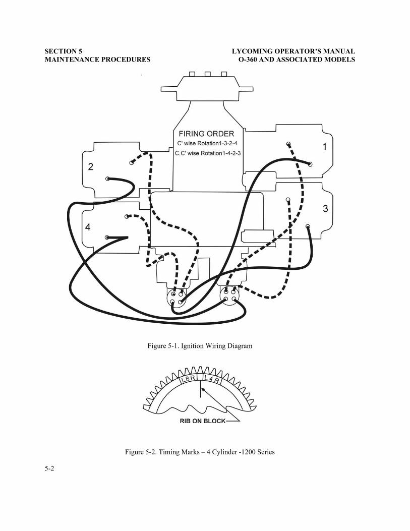
SECTION 5 LYCOMING OPERATOR’S MANUALMAINTENANCE PROCEDURES O-360 AND ASSOCIATED MODELS
Figure 5-1. Ignition Wiring Diagram
)LJXUH������7LPLQJ�0DUNV�±���&\OLQGHU�������6HULHV�
5-2
LYCOMING OPERATOR’S MANUAL SECTION 5O-360 AND ASSOCIATED MODELS MAINTENANCE PROCEDURES
(7) Hold the magneto in this position and install gasket and magnetos. Secure with clamps, washersand nuts tightened only finger tight.
(8) Using a battery powered timing light, attach one positive lead to left switch terminal, one positivelead to right switch terminal and the ground lead to the magneto housing.
(9) Turn the entire magneto in direction of rotation until the timing light comes on, then slowly turnit in the opposite direction until the light goes out. Bring the magneto back slowly until the lightjust comes on.
(10) Back off the crankshaft a few degrees, the timing lights should go out. Bring the crankshaftslowly back in direction of normal rotation until the lights just come on. Both lights should go on2° of No. 1 engine firing position.
NOTE
Some timing lights operate in the reverse manner as described. The light comes on when thebreaker points open. Check your timing light instructions.
c. Internal Timing – Dual Magneto – Check the magneto internal timing and breaker synchronization inthe following manner.
(1) Main Breakers – Connect the timing light negative lead to any unpainted surface of the magneto.Connect one positive lead to the left main breaker terminal and the second positive lead to theright main breaker terminal.
(2) Back the engine up a few degrees and again bump forward toward number one cylinder firingposition while observing timing lights. Both lights should go out to indicate opening of the mainbreakers when the timing pointer is indicating within�WKH�ZLGWK�RI�WKH�³/´�RU�³5´�PDUN��,I�EUHDNHU�timing is incorrect, loosen breaker screws and correct. Retorque breaker screws to 20-25 in.-lbs.
(3) Retard Breaker – Remove timing light leads from the main breaker terminals. Attach onepositive lead to retard breaker terminal, and second positive lead to the tachometer breakerterminal, if used.
(4) Back the engine up a few degrees and again bump forward toward number one cylinder firingposition until pointer is aligned with 15° retard timing mark. See Figure 5-6. Retard breakershould just open at this position.
(5) If retard timing is not correct, loosen cam securing screw and turn the retard breaker cam asrequired to make retard breaker open per paragraph c (4). Retorque cam screw to 16-20 in.-lbs.
(6) Observe the tachometer breaker is opened by the cam lobe. No synchronization of this breaker isrequired.
(7) Check action of impulse coupling (D-2000/3000 series only). With the ignition switch offobserve breaker cam end of rotor while manually cranking engine through a firing sequence.Rotor should alternately stop and then (with an audible snap) be rotated rapidly through a retardfiring position.
5-3
SECTION 5 LYCOMING OPERATOR’S MANUALMAINTENANCE PROCEDURES O-360 AND ASSOCIATED MODELS
d. Generator or Alternator Output – The generator or alternator (whichever is applicable) should bechecked to determine that the specified voltage and current are being obtained.
2. FUEL SYSTEM.
a. Repair of Fuel Leaks – In the event a line or fitting in the fuel system is replaced, only a fuel solublelubricant such as clean engine oil or Loctite Hydraulic Sealant may be used on tapered threads. Do notuse Teflon tape or any other form of thread compound. Do not apply sealant to the first two threads.
b. Carburetor or Fuel Injector (Except Simmonds Injectors) Fuel Inlet Screen Assembly – Remove theassembly and check the screen for distortion or openings in the strainer. Replace for either of theseconditions. Clean screen assembly in solvent and dry with compressed air and reinstall. The fuel inletscreen assembly is tightened to 35-40 in.-lbs. on carburetors and 65-70 in.-lbs. on fuel injectors. Thehex head plug on pressure carburetor is tightened to 160-175 in.-lbs.
c. Fuel Grade and Limitations – The recommended aviation grade fuel for the subject engines is listed inSection 3, Item 8.
In the event that the specified fuel is not available at some locations, it is permissible to use higheroctane fuel. Fuel of a lower octane than specified is not to be used. Under no circumstances shouldautomotive fuel be used (regardless of octane rating).
NOTE
It is recommended that personnel be familiar with latest revision of Service Instruction No.1070 regarding specified fuel for Lycoming engines.
d. Air Intake Ducts and Filter – Check all air intake ducts for dirt or restrictions. Inspect and service airfilters as instructed in thH�DLUIUDPH�PDQXIDFWXUHU¶V�KDQGERRN�
e. Idle Speed and Mixture Adjustment.
(1) Start the engine and warm up in the usual manner until oil and cylinder head temperatures arenormal.
���� &KHFN�PDJQHWRV��,I�WKH�³PDJ�GURS´�LV normal, proceed with idle adjustment.
(3) Set throttle stop screw so that the engine LGOHV� DW� WKH� DLUIUDPH� PDQXIDFWXUHU¶V� UHFRPPHQGHG�idling RPM. If the RPM changes appreciably after making idle mixture adjustment during thesucceeding steps, readjust the idle speed to the desired RPM.
(4) When the idling speed has been stabilized, move the cockpit mixture control lever with a smooth,VWHDG\�SXOO�WRZDUG�WKH�³,GOH�&XW�2II´�SRVLWLRQ�DQG�REVHUYH�WKH�Wachometer for any change duringthe leaning process. Caution must be exercised to return the mixture contURO� WR� WKH�³)XOO�5LFK´�position before the RPM can drop to a point where the engine cuts out. An increase of more than���530�ZKLOH�³OHDQLQJ�RXW´�LQGLFDWHV�DQ�H[FHVVLYHO\�rich idle mixture. An immediate decrease inRPM (if not preceded by a momentary increase) indicates the idle mixture is too lean.
5-4
LYCOMING OPERATOR’S MANUAL SECTION 5O-360 AND ASSOCIATED MODELS MAINTENANCE PROCEDURES
If step (4) indicates that the idle adjustment is too rich or too lean, turn the idle mixtureadjustment in direction required for correction, and check this new position by repeating the aboveprocedure. Make additional adjustments as necessary until a check results in a momentary pick-upof approximately 50 RPM. Each time the adjustment is changed, the engine should be run up to2000 RPM to clean the engine before proceeding with the RPM check. Make final adjustment ofthe idle speed adjustment to obtain the desired idling RPM with closed throttle. The above methodaims at a setting that will obtain maximum RPM with minimum manifold pressure. In case thesetting does not remain stable, check the idle linkage; any looseness in this linkage would causeerratic idling. In all cases, allowance should be made for the effect of weather conditions and fieldaltitude upon idling adjustment.
3. LUBRICATION SYSTEM.
a. Oil Grades and Limitations – Service the engine in accordance with the recommended grade oil asspecified in Section 3, Item 8.
b. Oil Suction and Oil Pressure Screens – At each 100-hour inspection remove suction screen. Inspectfor metal particles; clean and reinstall. Inspect and clean pressure screen every 25 hours.
c. Oil Pressure Relief Valve – Subject engines may be equipped with either an adjustable or non-adjustable oil pressure relief valve. A brief description of both types follows:
(1) Non-Adjustable Oil Pressure Relief Valve – The function of the oil pressure relief valve is tomaintain engine oil pressure within specified limits. The valve, although not adjustable, maycontrol the oil pressure with the addition of a maximum of nine (9) P/N STD-425 washersbetween the cap and spring to increase the pressure. Removal of the washers will decrease the oilpressure. Some early model engines use a maximum of three (3) P/N STD-425 washers toincrease the oil pressure and the use of a P/N 73629 or P/N 73630 spacer between the cap andcrankcase to decrease the oil pressure. Particles of metal or other foreign matter lodged betweenthe ball and seal will result in faulty readings. It is advisable, therefore, to disassemble, inspectand clean the valve if excessive pressure fluctuations are noted.
(2) Oil Pressure Relief Valve (Adjustable) – The adjustable oil relief valve enables the operator tomaintain engine oil pressure within the specified limits. If pressure under normal operatingconditions should consistently exceed the maximum or minimum specified limits, adjust thevalve as follows:
With the engine warmed up and running at approximately 2000 RPM, observe the reading onthe oil pressure gage. If the pressure is above maximum or below minimum specified limits, stopengine and screw the adjusting screw outward to decrease pressure or inward to increasepressure. Depending on installation, the adjusting screw may have only a screw driver slot and isturned with a screw driver; or may have the screw driver slot plus a pinned .375-24 castellatednut and may be turned with either a screw driver or a box wrench.
4. CYLINDERS. It is recommended that as a field operation, cylinder maintenance be confined toreplacement of the entire assembly. For valve replacement, consult the proper overhaul manual. This shouldbe undertaken only as an emergency measure.
5-5
SECTION 5 LYCOMING OPERATOR’S MANUALMAINTENANCE PROCEDURES O-360 AND ASSOCIATED MODELS
a. Removal of Cylinder Assembly.
(1) Remove exhaust manifold.
(2) Remove rocker box drain tube, intake pipe, baffle and any clips that might interfere with theremoval of the cylinder.
(3) Disconnect ignition cables and remove the bottom spark plug.
(4) Remove rocker box cover and rotate crankshaft until piston is approximately at top center of thecompression stroke. This is indicated by a positive pressure inside of cylinder tending to pushthumb off of bottom spark plug hole.
(5) Slide valve rocker shafts from cylinder head and remove the valve rockers. Valve rocker shaftscan be removed when the cylinder is removed from the engine. Remove rotator cap from exhaustvalve stem.
(6) Remove push rods by grasping ball end and pulling rod out of shroud tube. Detach shroud tubespring and lock plate and pull shroud tubes through holes in cylinder head.
NOTE
The hydraulic tappets, push rods, rocker arms and valves must be assembled in the samelocation from which they were removed.
(7) Remove cylinder base nuts and hold down plates (where employed) then remove cylinder bypulling directly away from crankcase. Be careful not to allow the piston to drop against thecrankcase, as the piston leaves the cylinder.
b. Removal of Piston from Connecting Rod – Remove the piston pin plugs. Insert piston pin pullerthrough piston pin, assemble puller nut; then proceed to remove piston pin. Do not allow connectingrod to rest on the cylinder bore of the crankcase. Support the connecting rod with heavy rubber band,discarded cylinder base oil ring seal, or any other non-marring method.
c. Removal of Hydraulic Tappet Sockets and Plunger Assemblies – It will be necessary to remove andbleed the hydraulic tappet plunger assembly so that dry tappet clearance can be checked when thecylinder assembly is reinstalled. This is accomplished in the following manner:
(1) Remove the hydraulic tappet push rod socket by inserting the forefinger into the concave end ofthe socket and withdrawing. If the socket cannot be removed in this manner, it may be removedby grasping the edge of the socket with a pair of needle nose pliers. However, care must beexercised to avoid scratching the socket.
(2) To remove the hydraulic tappet plunger assembly, use the special Lycoming service tool. In theevent the tool is not available, the hydraulic tappet plunger assembly may be removed by a hookin the end of a short piece of lockwire, inserting the wire so that the hook engages the spring ofthe plunger assembly. Draw the plunger assembly out of the tappet body by gently pulling thewire.
5-6
LYCOMING OPERATOR’S MANUAL SECTION 5O-360 AND ASSOCIATED MODELS MAINTENANCE PROCEDURES
CAUTION
NEVER USE A MAGNET TO REMOVE HYDRAULIC PLUNGER ASSEMBLIES FROMTHE CRANKCASE. THIS CAN CAUSE THE CHECK BALL TO REMAIN OFF ITS SEAT,RENDERING THE UNIT INOPERATIVE.
d. Assembly of Hydraulic Tappet Plunger Assemblies – To assemble the unit, unseat the ball by insertinga thin clean wire through the oil inlet hole. With the ball off its seat, insert the plunger and twistclockwise so that the spring catches. All oil must be removed before the plunger is inserted.
e. Assembly of Cylinder and Related Parts – Rotate the crankshaft so that the connecting rod of thecylinder being assembled is at the top center of compression stroke. This can be checked by placingtwo fingers on the intake and exhaust tappet bodies. Rock crankshaft back and forth over top center. Ifthe tappet bodies do not move the crankshaft is on the compression stroke.
(1) Place each plunger assembly in its respective tappet body and assemble the socket on top ofplunger assembly.
(2) Assemble piston with rings so that the number stamped on the piston pin boss is toward the frontof the engine. The piston pin should be a handpush fit. If difficulty is experienced in inserting thepiston pin, it is probably caused by carbon or burrs in the piston pin hole. During assembly,always use a generous quantity of oil, both in the piston hole and on the piston pin.
(3) Assemble one piston pin plug at each end of the piston pin and place a new rubber oil seal ringaround the cylinder skirt. Coat piston and rings and the inside of the cylinder generously with oil.
(4) Using a piston ring compressor, assemble the cylinder over the piston so that the intake port is atthe bottom of the engine. Push the cylinder all the way on, catching the ring compressor as it ispushed off.
NOTE
Before installing cylinder hold-down nuts, lubricate crankcase thru-stud threads with anyone of the following lubricants, or combination of lubricants1. 90% SAE 50W engine oil and 10% STP.2. Parker Thread Lube.3. 60% SAE 30 engine oil and 40% Parker Thread Lube.
(5) Assemble hold-down plates (where applicable) and cylinder base hold-down nuts and tighten asdirected in the following steps.
NOTE
At any time a cylinder is replaced, it is necessary to retorque the thru-studs on the cylinderon the opposite side of the engine.
(a) (Engines using hold-down plates) – Install shims between cylinder base hold-down plates andcylinder barrel, as directed in Figure 5-3, and tighten ½ inch hold-down nuts to 300 in.-lbs.(25 ft.-lbs.) torque, using the sequence shown in Figure 5-3.
5-7
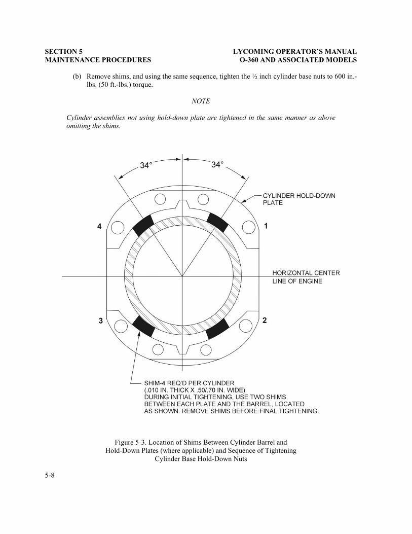
SECTION 5 LYCOMING OPERATOR’S MANUALMAINTENANCE PROCEDURES O-360 AND ASSOCIATED MODELS
(b) Remove shims, and using the same sequence, tighten the ½ inch cylinder base nuts to 600 in.-lbs. (50 ft.-lbs.) torque.
NOTE
Cylinder assemblies not using hold-down plate are tightened in the same manner as aboveomitting the shims.
Figure 5-3. Location of Shims Between Cylinder Barrel andHold-Down Plates (where applicable) and Sequence of Tightening
Cylinder Base Hold-Down Nuts
5-8
LYCOMING OPERATOR’S MANUAL SECTION 5O-360 AND ASSOCIATED MODELS MAINTENANCE PROCEDURES
(c) Tighten the inch hold-down nuts to 300 in.-lbs. (25 ft.-lbs.) torque. Sequence of tighteningis optional.
(d) As a final check, hold the torque wrench on each nut for about five seconds. If the nut doesnot turn, it may be presumed to be tightened to correct torque.
CAUTION
AFTER ALL CYLINDER BASE NUTS HAVE BEEN TIGHTENED, REMOVE ANY NICKS INTHE CYLINDER FINS BY FILING OR BURRING.
(6) Install new shroud tube oil seals on both ends of shroud tube. Install shroud tube and lock inplace as required for type of cylinder.
(7) Assemble each push rod in its respective shroud tube, and assemble each rocker in its respectiveposition by placing rocker between bosses and sliding valve rocker shaft in place to retain rocker.Before installing exhaust valve rocker, place rotator cap over end of exhaust valve stem.
(8) Be sure that the piston is at top center of compression stroke and that both valves are closed.Check clearance between the valve stem tip and the valve rocker. In order to check this clearance,place the thumb of one hand on the valve rocker directly over the end of the push rod and pushdown so as to compress the hydraulic tappet spring. While holding the spring compressed, thevalve clearance should be between .028 and .080 inch. If clearance does not come within theselimits, remove the push rod and insert a longer or shorter push rod, as required, to correctclearance.
NOTE
Inserting a longer push rod will decrease the valve clearance.
(9) Install intercylinder baffles, rocker box covers, intake pipes, rocker box drain tubes and exhaustmanifold.
5. GENERATOR OR ALTERNATOR DRIVE BELT TENSION.
Check the tension of a new belt 25 hours after installation. Refer to latest revision of Service InstructionNo. 1129 and latest revision of Service Letter No. L160 for methods of checking generator or alternatordrive belt tension.
6. TURBOCHARGER CONTROLS.
a. Density Controller – The density controller is adjusted at the factory to maintain a predeterminedconstant for desired horsepower.
The density controller is set to the curve, see Figure 5-4, under the following conditions: Enginestabilized at operating conditions, full throttle with oil pressure at 80 psi ± 5 psi.
If it is suspected that the manifold pressure is not within limits, it may be checked to the curve.
EXAMPLE
Operating at the stated conditions with a compressor discharge temperature of 120°F, themanifold pressure should be 34.8 in. Hg. ± .3 in. Hg.
5-9

SECTON 5 LYCOMING OPERATOR’S MANUALMAINTENANCE PROCEDURES O-360 AND ASSOCIATED MODELS
If the manifold pressure is found to be out of limits, the cause might be found either in the densitycontroller, the differential pressure controller, or the waste gate. It is recommended that an authorizedoverhaul facility check these controls.
Exhaust Bypass Valve (TIO-360-A Series).
This valve is actuated by engine oil pressure and is set to predetermined open and closed clearances.These clearances and the procedures for setting them are shown in Figure 5-5.
Exhaust Bypass Valve (TIO-360-C1A6D).
This valve is mechanically controlled by a flexible linkage connected to the injector throttle arm and thewastegate control arm.
Adjust linkage as follows:
(1) Move injector throttle arm to full open position.
(2) Insert a .005-.015 inch feeler gage between the bypass butterfly valve, in the closed position, andthe bypass housing.
(3) Adjust linkage until the bypass valve control arm is at the full closed stop position.
5-10
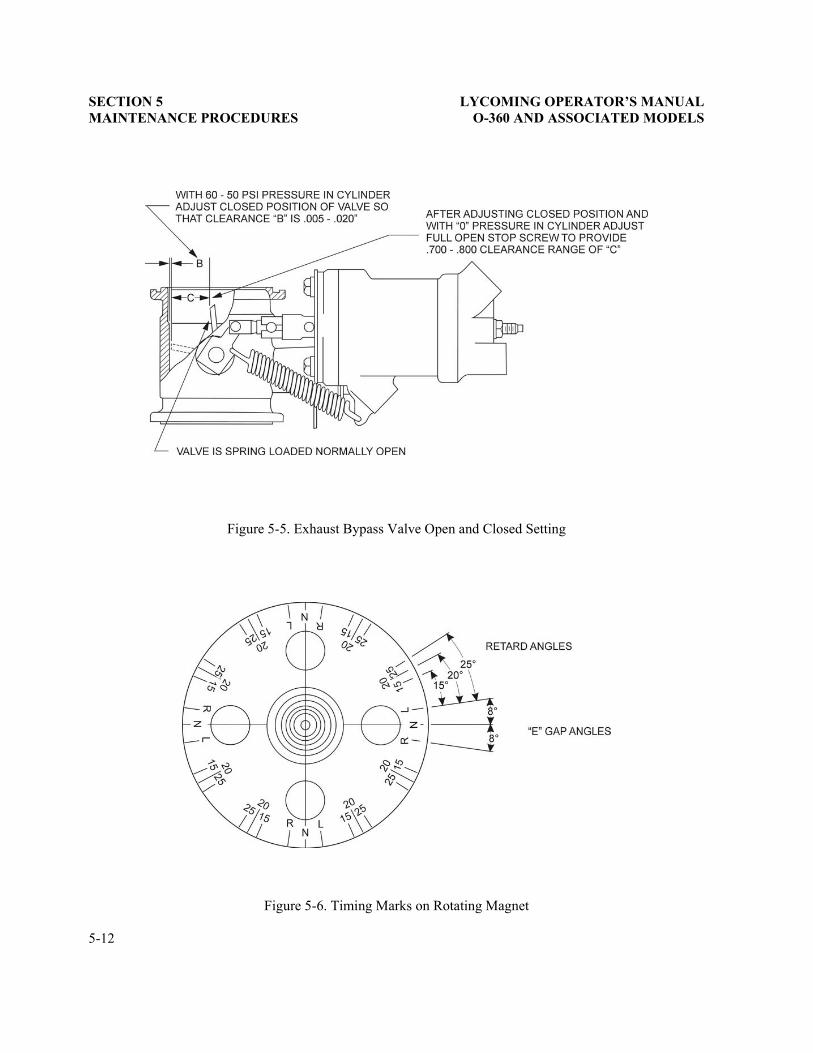
SECTION 5 LYCOMING OPERATOR’S MANUALMAINTENANCE PROCEDURES O-360 AND ASSOCIATED MODELS
Figure 5-5. Exhaust Bypass Valve Open and Closed Setting
Figure 5-6. Timing Marks on Rotating Magnet
5-12
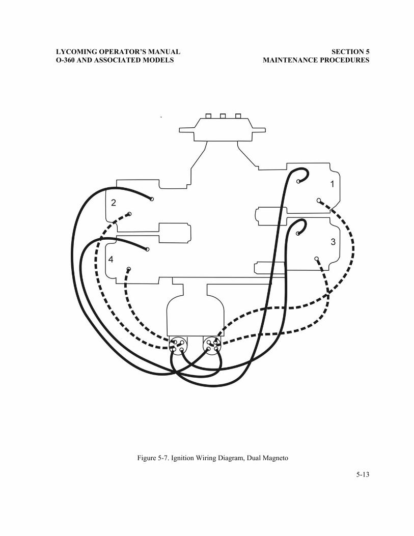
LYCOMING OPERATOR’S MANUAL SECTION 5O-360 AND ASSOCIATED MODELS MAINTENANCE PROCEDURES
Figure 5-7. Ignition Wiring Diagram, Dual Magneto
5-13
LYCOMING OPERATOR’S MANUAL
SECTION 6TROUBLE-SHOOTING – ENGINE
Page
Failure of Engine to Start............................................................................................................................ 6-1
Failure of Engine to Idle Properly.............................................................................................................. 6-2
Low Power and Uneven Running............................................................................................................... 6-2
Failure of Engine to Develop Full Power................................................................................................... 6-3
Rough Engine ............................................................................................................................................... 6-3
Low Oil Pressure.......................................................................................................................................... 6-3
High Oil Temperature ................................................................................................................................. 6-3
Excessive Oil Consumption......................................................................................................................... 6-4
TROUBLE-SHOOTING – TURBOCHARGER
Excessive Noise or Vibration....................................................................................................................... 6-4
Engine Will Not Deliver Rated Power ....................................................................................................... 6-4
Critical Altitude Lower Than Specified..................................................................................................... 6-5
Engine Surges or Smokes ............................................................................................................................ 6-6
High Deck Pressure...................................................................................................................................... 6-6
LYCOMING OPERATOR’S MANUAL SECTION 6O-360 AND ASSOCIATED MODELS TROUBLE-SHOOTING
SECTION 6
TROUBLE-SHOOTING
Experience has proven that the best method of trouble-shooting is to decide on the various causes of agiven trouble and then to eliminate causes one by one, beginning with the most probable. The followingcharts list some of the more common troubles, which may be encountered in maintaining engines andturbochargers; their probable causes and remedies.
1. TROUBLE-SHOOTING – ENGINE.
TROUBLE PROBABLE CAUSE REMEDY
Failure of Engine to Start Lack of fuel Check fuel system for leaks.Fill fuel tank. Clean dirty lines,strainers, or fuel valves.
� � � � � 2YHUSULPLQJ� � � � /HDYH�LJQLWLRQ�³RII´�DQG�PL[WXUH�� � � � � � � � � � FRQWURO�LQ�³,GOH�&XW�2II´��RSHQ�� � � � � � � � � � WKURWWOH�DQG�³XQORDG´�HQJLQH�E\�
cranking for a few seconds. Turnignition switch on and proceed tostart in a normal manner.
Defective spark plugs Clean and adjust or replace sparkplugs.
Defective ignition wire Check with electric tester, andreplace any defective wires.
Defective battery Replace with charged battery.
Improper operation of magneto Clean points. Check internalbreaker timing of magnetos.
Lack of sufficient fuel flow Disconnect fuel line and checkfuel flow.
Water in fuel injector or carb. Drain fuel injector or carburetorand fuel lines.
Internal failure Check oil screens for metalparticles. If found, completeoverhaul of the engine may beindicated.
6-1
SECTION 6 LYCOMING OPERATOR’S MANUALTROUBLE-SHOOTING O-360 AND ASSOCIATED MODELS
TROUBLE PROBABLE CAUSE REMEDY
Failure of Engine to Idle Properly Incorrect idle mixture Adjust mixture.
Leak in the induction system Tighten all connections in theinduction system. Replace anyparts that are defective.
Incorrect idle mixture Adjust throttle stop to obtaincorrect idle.
Uneven cylinder compression Check condition of piston ringsand valve seats.
Faulty ignition system Check entire ignition system.
Insufficient fuel pressure Adjust fuel pressure.
Low Power and Uneven Running Mixture too rich indicated by Readjustment of fuel injector orsluggish engine operation, red carburetor by authorizedexhaust flame at night. Extreme personnel is indicated.cases indicated by black smokefrom exhaust.
Mixture too lean indicated by Check fuel lines for dirt or otheroverheating or backfiring restrictions. Readjustment of fuel
injector or carburetor by author-ized personnel is indicated.
Leaks in induction system Tighten all connections. Replacedefective parts.
Defective spark plugs Clean and gap or replace sparkplugs.
Improper fuel Fill tank with fuel of recom-mended grade.
Magneto breaker points not Clean points. Check internalworking properly timing of magnetos.
Defective ignition wire Check wire with electric tester.Replace defective wire.
Defective spark plug terminal Replace connectors on spark plugconnectors wire.
6-2
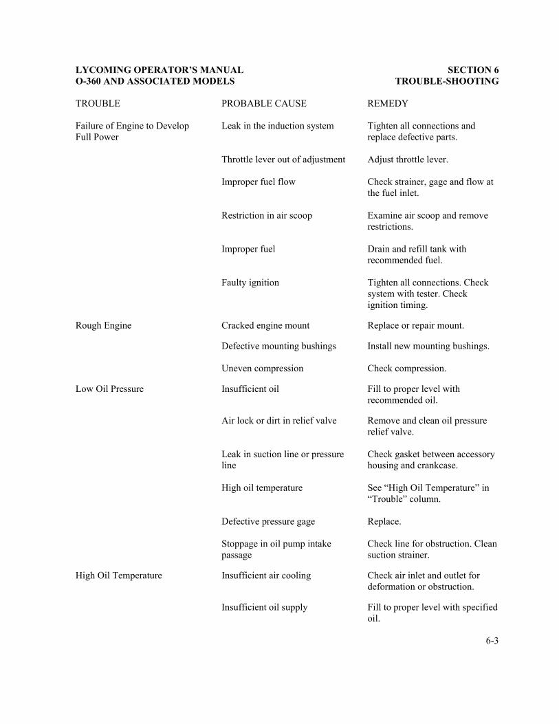
LYCOMING OPERATOR’S MANUAL SECTION 6O-360 AND ASSOCIATED MODELS TROUBLE-SHOOTING
TROUBLE PROBABLE CAUSE REMEDY
Failure of Engine to Develop Leak in the induction system Tighten all connections andFull Power replace defective parts.
Throttle lever out of adjustment Adjust throttle lever.
Improper fuel flow Check strainer, gage and flow atthe fuel inlet.
Restriction in air scoop Examine air scoop and removerestrictions.
Improper fuel Drain and refill tank withrecommended fuel.
Faulty ignition Tighten all connections. Checksystem with tester. Checkignition timing.
Rough Engine Cracked engine mount Replace or repair mount.
Defective mounting bushings Install new mounting bushings.
Uneven compression Check compression.
Low Oil Pressure Insufficient oil Fill to proper level withrecommended oil.
Air lock or dirt in relief valve Remove and clean oil pressurerelief valve.
Leak in suction line or pressure Check gasket between accessoryline housing and crankcase.
+LJK�RLO�WHPSHUDWXUH� 6HH�³+LJK�2LO�7HPSHUDWXUH´�LQ�³7URXEOH´�FROXPQ��
Defective pressure gage Replace.
Stoppage in oil pump intake Check line for obstruction. Cleanpassage suction strainer.
High Oil Temperature Insufficient air cooling Check air inlet and outlet fordeformation or obstruction.
Insufficient oil supply Fill to proper level with specifiedoil.
6-3
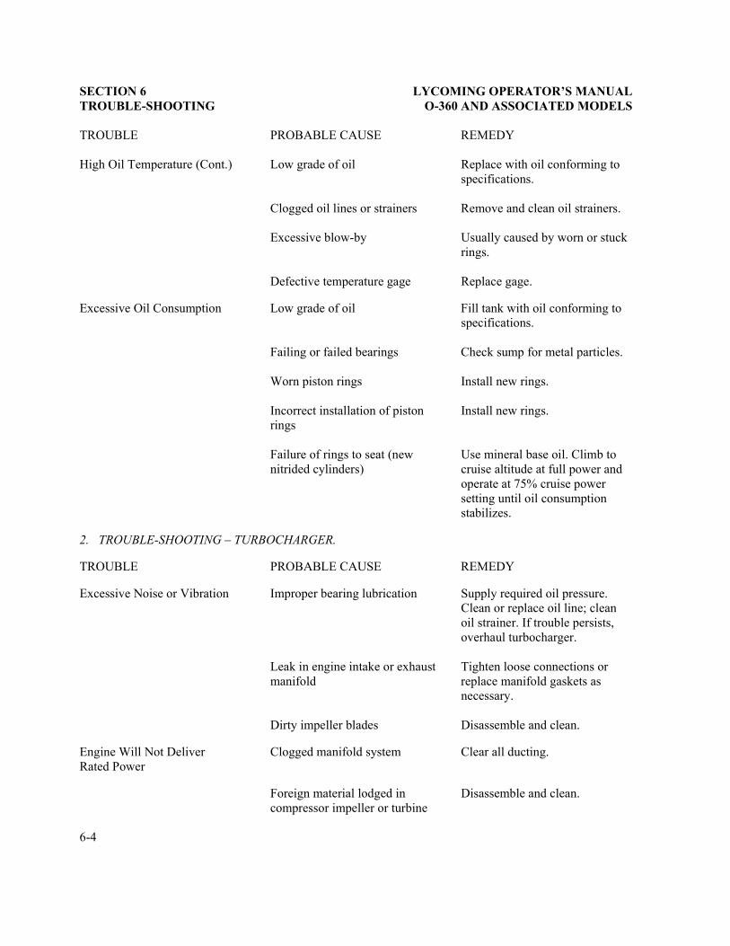
SECTION 6 LYCOMING OPERATOR’S MANUALTROUBLE-SHOOTING O-360 AND ASSOCIATED MODELS
TROUBLE PROBABLE CAUSE REMEDY
High Oil Temperature (Cont.) Low grade of oil Replace with oil conforming tospecifications.
Clogged oil lines or strainers Remove and clean oil strainers.
Excessive blow-by Usually caused by worn or stuckrings.
Defective temperature gage Replace gage.
Excessive Oil Consumption Low grade of oil Fill tank with oil conforming tospecifications.
Failing or failed bearings Check sump for metal particles.
Worn piston rings Install new rings.
Incorrect installation of piston Install new rings.rings
Failure of rings to seat (new Use mineral base oil. Climb tonitrided cylinders) cruise altitude at full power and
operate at 75% cruise powersetting until oil consumptionstabilizes.
2. TROUBLE-SHOOTING – TURBOCHARGER.
TROUBLE PROBABLE CAUSE REMEDY
Excessive Noise or Vibration Improper bearing lubrication Supply required oil pressure.Clean or replace oil line; cleanoil strainer. If trouble persists,overhaul turbocharger.
Leak in engine intake or exhaust Tighten loose connections ormanifold replace manifold gaskets as
necessary.
Dirty impeller blades Disassemble and clean.
Engine Will Not Deliver Clogged manifold system Clear all ducting.Rated Power
Foreign material lodged in Disassemble and clean.compressor impeller or turbine
6-4
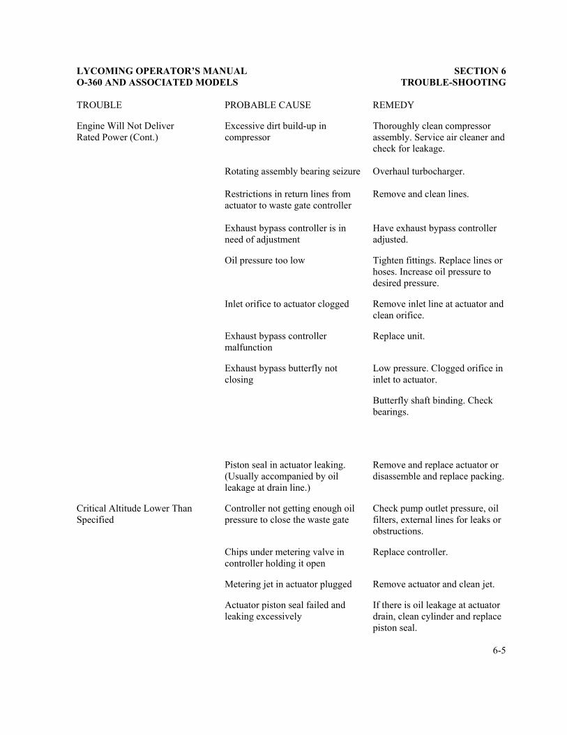
LYCOMING OPERATOR’S MANUAL SECTION 6O-360 AND ASSOCIATED MODELS TROUBLE-SHOOTING
TROUBLE PROBABLE CAUSE REMEDY
Engine Will Not Deliver Excessive dirt build-up in Thoroughly clean compressorRated Power (Cont.) compressor assembly. Service air cleaner and
check for leakage.
Rotating assembly bearing seizure Overhaul turbocharger.
Restrictions in return lines from Remove and clean lines.actuator to waste gate controller
Exhaust bypass controller is in Have exhaust bypass controllerneed of adjustment adjusted.
Oil pressure too low Tighten fittings. Replace lines orhoses. Increase oil pressure todesired pressure.
Inlet orifice to actuator clogged Remove inlet line at actuator andclean orifice.
Exhaust bypass controller Replace unit.malfunction
Exhaust bypass butterfly not Low pressure. Clogged orifice inclosing inlet to actuator.
Butterfly shaft binding. Checkbearings.
Turbocharger impeller binding, Check bearings. Replacefrozen or fouling housing turbocharger.
Piston seal in actuator leaking. Remove and replace actuator or(Usually accompanied by oil disassemble and replace packing.leakage at drain line.)
Critical Altitude Lower Than Controller not getting enough oil Check pump outlet pressure, oilSpecified pressure to close the waste gate filters, external lines for leaks or
obstructions.
Chips under metering valve in Replace controller.controller holding it open
Metering jet in actuator plugged Remove actuator and clean jet.
Actuator piston seal failed and If there is oil leakage at actuatorleaking excessively drain, clean cylinder and replace
piston seal.
6-5
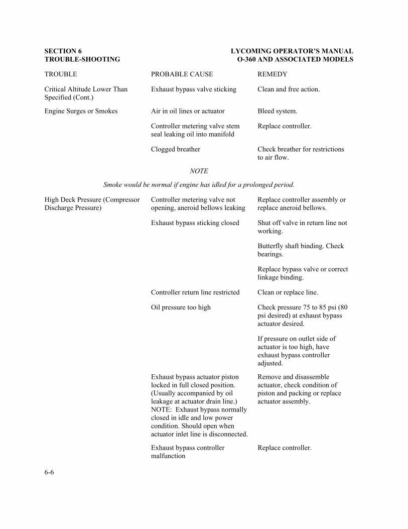
SECTION 6 LYCOMING OPERATOR’S MANUALTROUBLE-SHOOTING O-360 AND ASSOCIATED MODELS
TROUBLE PROBABLE CAUSE REMEDY
Critical Altitude Lower Than Exhaust bypass valve sticking Clean and free action.Specified (Cont.)
Engine Surges or Smokes Air in oil lines or actuator Bleed system.
Controller metering valve stem Replace controller.seal leaking oil into manifold
Clogged breather Check breather for restrictionsto air flow.
NOTE
Smoke would be normal if engine has idled for a prolonged period.
High Deck Pressure (Compressor Controller metering valve not Replace controller assembly orDischarge Pressure) opening, aneroid bellows leaking replace aneroid bellows.
Exhaust bypass sticking closed Shut off valve in return line notworking.
Butterfly shaft binding. Checkbearings.
Replace bypass valve or correctlinkage binding.
Controller return line restricted Clean or replace line.
Oil pressure too high Check pressure 75 to 85 psi (80psi desired) at exhaust bypassactuator desired.
If pressure on outlet side ofactuator is too high, haveexhaust bypass controlleradjusted.
Exhaust bypass actuator piston Remove and disassemblelocked in full closed position. actuator, check condition of(Usually accompanied by oil piston and packing or replaceleakage at actuator drain line.) actuator assembly.NOTE: Exhaust bypass normallyclosed in idle and low powercondition. Should open whenactuator inlet line is disconnected.
Exhaust bypass controller Replace controller.malfunction
6-6
LYCOMING OPERATOR’S MANUAL
SECTION 7INSTALLATION AND STORAGE
Page
Preparation of Engine for Installation....................................................................................................... 7-1
General....................................................................................................................................................... 7-1
Inspection of Engine Mounting ............................................................................................................... 7-1
Attaching Engine to Mounts .................................................................................................................... 7-1
Oil and Fuel Line Connections ................................................................................................................ 7-1
Propeller Installation ................................................................................................................................ 7-2
Preparation of Carburetors and Fuel Injectors for Installation ............................................................. 7-2
Corrosion Prevention in Engines Installed in Inactive Aircraft.............................................................. 7-2
LYCOMING OPERATOR’S MANUAL SECTION 7O-360 AND ASSOCIATED MODELS INSTALLATION AND STORAGE
SECTION 7
INSTALLATION AND STORAGE
1. PREPARATION OF ENGINE FOR INSTALLATION. Before installing an engine that has been preparedfor storage, remove all dehydrator plugs, bags of desiccant and preservative oil from the engine.Preservative oil can be removed by removing the bottom spark plugs and turning the crankshaft three orfour revolutions by hand. The preservative oil will then drain through the spark plug holes. Draining will befacilitated if the engine is tilted from side to side during the above operation. Preservative oil which hasaccumulated in the sump can be drained by removing the oil sump plug. Engines that have been stored in acold place should be removed to an environment of at least 70°F (21°C) for a period of 24 hours beforepreservative oil is drained from the cylinders. If this is not possible, heat the cylinders with heat lampsbefore attempting to drain the engine.
After the oil sump has been drained, the plug should be replaced and safety-wired. Fill the sump orexternal tank with lubricating oil. The crankshaft should again be turned several revolutions to saturate theinterior of the engine with the clean oil. When installing spark plugs, make sure that they are clean, if not,wash them in clean petroleum solvent. Of course, there will be a small amount of preservative oil remainingin the engine, but this can cause no harm. However, after twenty-five hours of operation, the lubricating oilshould be drained while the engine is hot. This will remove any residual preservative oil that may have beenpresent.
CAUTION
DO NOT ROTATE THE CRANKSHAFT OF AN ENGINE CONTAINING PRESERVATIVEOIL BEFORE REMOVING THE SPARK PLUGS, BECAUSE IF THE CYLINDERSCONTAIN ANY APPRECIABLE AMOUNT OF THE MIXTURE, THE RESULTINGACTION, KNOWN AS HYDRAULICING, WILL CAUSE DAMAGE TO THE ENGINE.ALSO, ANY CONTACT OF THE PRESERVATIVE OIL WITH PAINTED SURFACESSHOULD BE AVOIDED.
General – Should any of the dehydrator plugs, containing crystals of silica-gel or similar material, be brokenduring their term of storage or upon their removal from the engine, and if any of the contents should fall intothe engine, that portion of the engine must be disassembled and thoroughly cleaned before using the engine.The oil strainers should be removed and cleaned in gasoline or some other hydrocarbon solvent. The fueldrain screen located in the fuel inlet of the carburetor or fuel injector should also be removed and cleaned ina hydrocarbon solvent. The operator should also note if any valves are sticking. If they are, this conditioncan be eliminated by coating the valve stem generously with a mixture of gasoline and lubrication oil.
Inspection of Engine Mounting – If the aircraft is one from which an engine has been removed, make surethat the engine mount is not bent or damaged by distortion or misalignment as this can produce abnormalstresses with the engine.
Attaching Engine to Mounts – 6HH�DLUIUDPH�PDQXIDFWXUHU¶V�UHFRPPHndations for method of mounting theengine.
Oil and Fuel Line Connections – The oil and fuel line connections are called out on the accompanyinginstallation drawings.
7-1
SECTION 7 LYCOMING OPERATOR’S MANUALINSTALLATION AND STORAGE O-360 AND ASSOCIATED MODELS
Propeller Installation – Consult the airframe manufacturer for information relative to propeller installation.
1. PREPARATION OF CARBURETORS AND FUEL INJECTORS FOR INSTALLATION.
Carburetors and fuel injectors that have been prepared for storage should undergo the followingprocedures before being placed in service.
Carburetor (MA-4-5, MA-4-5AA) – Remove the fuel drain plug and drain preservative oil. Remove the fuelinlet strainer assembly and clean in a hydrocarbon solvent. Reinstall the fuel drain plug and fuel inletstrainer assembly.
Carburetor (PSH-5BD) – Remove the fuel inlet strainer and all plugs leading to the fuel chambers. Drainpreservative oil from the carburetor. Clean the fuel inlet strainer in a hydrocarbon solvent. Reinstall fuelinlet strainer and replace all plugs.
Remove plug opposite the manual mixture control needle and drain any accumulated moisture from the airchamber. Replace plug.
With the throttle lever in the wide open position and the manual mixture control in the full rich position,inject clean fuel through the fuel inlet connection at 5 psi until clean fuel flows from the discharge nozzle.
CAUTION
DO NOT ALLOW FUEL OR OIL TO ENTER INTO THE AIR CHAMBER.
Move the throttle lever to the closed position and the mixture control lever to the idle cut-off position.Because this carburetor has a closed fuel system, it will remain full of fuel as long as the mixture controllever is in the idle cut-off position.
NOTE
It is necessary that this carburetor soak for an eight hour period before starting the engine.The soaking period may be performed prior to or after installation on the engine.
Fuel Injector (Bendix) – Remove and clean the fuel inlet strainer assembly and reinstall. Inject clean fuelinto the fuel inlet connection with the fuel outlets uncapped until clean fuel flow from the outlets. Do notexceed 15 psi inlet pressure.
CORROSION PREVENTION IN ENGINES INSTALLED IN INACTIVE AIRCRAFT
Corrosion can occur, especially in new or overhauled engines, on cylinder walls of engines that will beinoperative for periods as brief as two days. Therefore, the following preservation procedure isrecommended for inactive engines and will be effective in minimizing the corrosion condition for a periodup to thirty days.
NOTE
Ground running the engine for brief periods of time is not a substitute for the followingprocedure; in fact, the practice of ground running will tend to aggravate rather thanminimize this corrosion condition
7-2
LYCOMING OPERATOR’S MANUAL SECTION 7O-360 AND ASSOCIATED MODELS INSTALLATION AND STORAGE
a. As soon as possible after the engine is stopped, move the aircraft into the hangar, or other shelterwhere the preservation process is to be performed.
b. Remove sufficient cowling to gain access to the spark plugs and remove both spark plugs from eachcylinder.
c. Spray the interior of each cylinder with approximately two (2) ounces of corrosion preventive oilwhile cranking the engine about five (5) revolutions with the starter. The spray gun nozzle may beplaced in either of the spark plug holes.
NOTE
Spraying should be accomplished using an airless spray gun (Spraying Systems Co.,“Gunjet” Model 24A-8395 or equivalent). In the event an airless spray gun is not available,personnel should install a moisture trap in the air line of a conventional spray gun and becertain oil is hot at the nozzle before spraying cylinders.
d. With the crankshaft stationary, again spray each cylinder through the spark plug holes withapproximately two (2) ounces of corrosion preventive oil. Assemble spark plugs and do not turncrankshaft after cylinders have been sprayed.
The corrosion preventive oil to be used in the foregoing procedure should conform to specification MIL-L-6529, Type 1, heated to 200°F/220°F (93°C/104°C) spray nozzle temperature. It is not necessary to flushpreservative oil from the cylinder prior to flying the aircraft. The small quantity of oil coating the cylinderswill be expelled from the engine during the first few minutes of operation.
NOTE
Oils of the type mentioned are to be used in Lycoming aircraft engines for corrosionprevention only, and not for lubrication. See the latest revision of Lycoming ServiceInstruction No. 1014 and latest revision of Service Bulletin No. 318 for recommendedlubricating oil.
7-3
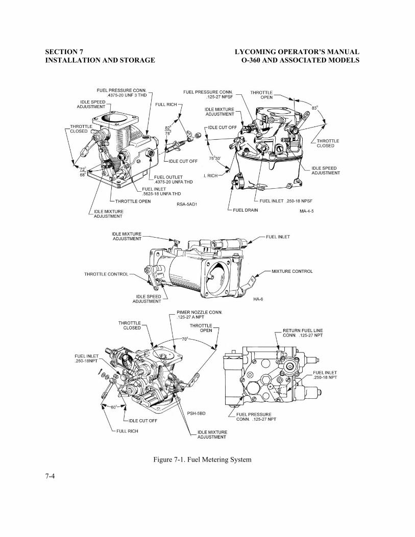
SECTION 7 LYCOMING OPERATOR’S MANUALINSTALLATION AND STORAGE O-360 AND ASSOCIATED MODELS
Figure 7-1. Fuel Metering System
7-4
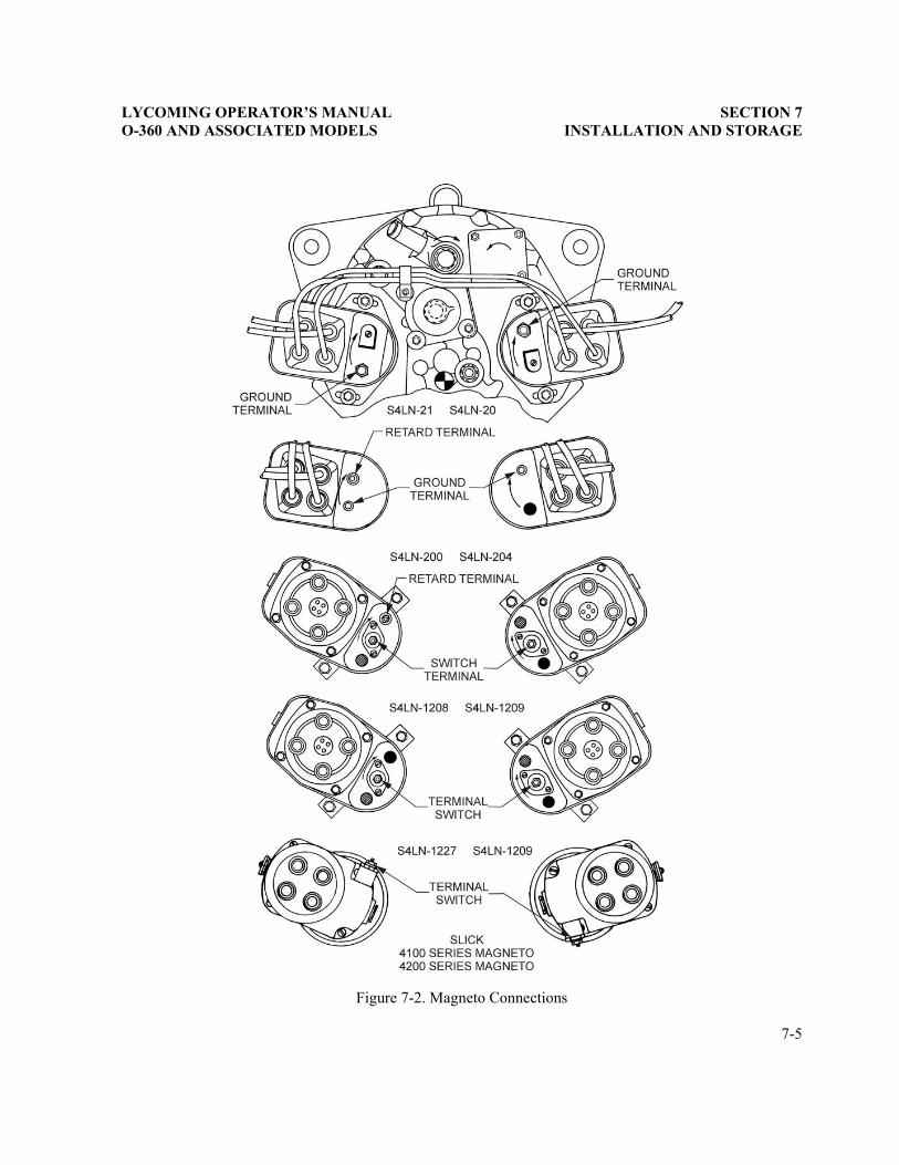
LYCOMING OPERATOR’S MANUAL SECTION 7O-360 AND ASSOCIATED MODELS INSTALLATION AND STORAGE
Figure 7-2. Magneto Connections
7-5
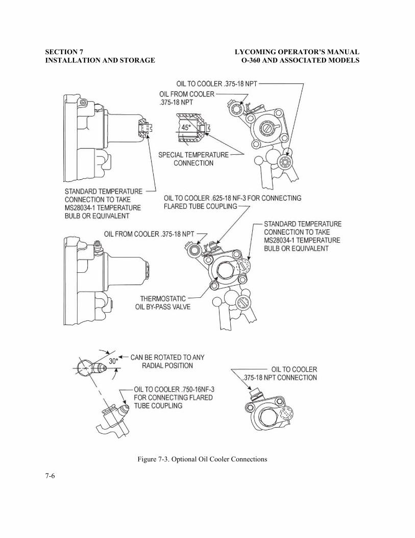
SECTION 7 LYCOMING OPERATOR’S MANUALINSTALLATION AND STORAGE O-360 AND ASSOCIATED MODELS
Figure 7-3. Optional Oil Cooler Connections
7-6
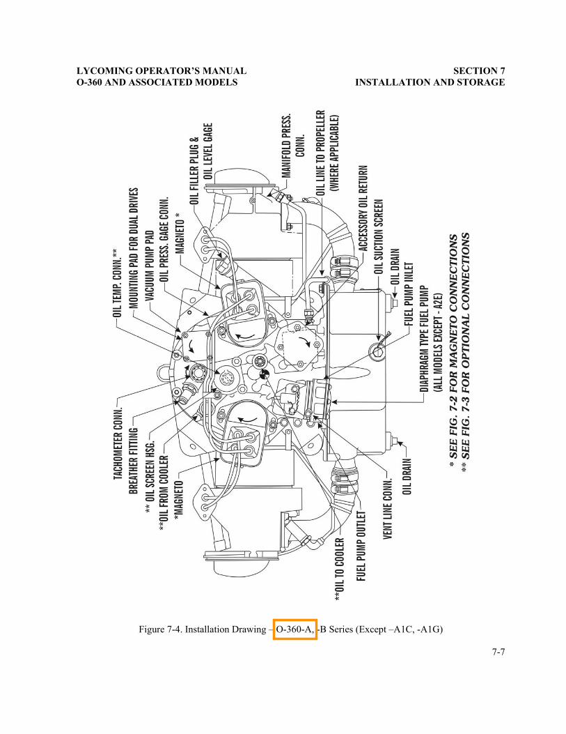
LYCOMING OPERATOR’S MANUAL SECTION 7O-360 AND ASSOCIATED MODELS INSTALLATION AND STORAGE
Figure 7-4. Installation DrDZLQJ�±�2�����$���%�6HULHV��([FHSW�±$�&���$�*��
7-7
LYCOMING OPERATOR’S MANUAL
SECTION 8TABLES
Page
Table of Limits ............................................................................................................................................. 8-1
Ground Run After Top Overhaul .............................................................................................................. 8-2
Flight Test After Top Overhaul.................................................................................................................. 8-3
Full Throttle HP at Altitude........................................................................................................................ 8-4
Table of Speed Equivalents ......................................................................................................................... 8-4
Centigrade – Fahrenheit Conversion Table .............................................................................................. 8-5
Inch Fraction Conversions .......................................................................................................................... 8-6
LYCOMING OPERATOR’S MANUAL SECTION 8O-360 AND ASSOCIATED MODELS TABLES
SECTION 8
TABLES
FOR TIGHTENING TORQUE RECOMMENDATIONS AND INFORMATION
CONCERNING TOLERANCES AND DIMENSIONS THAT MUST BE MAINTAINED
IN LYCOMING AIRCRAFT ENGINES, CONSULT THE LATEST EDITION OF
SPECIAL SERVICE PUBLICATION NO. SSP-1776.
CONSULT LATEST REVISION OF SERVICE INSTRUCTION NO. 1029 FOR
INFORMATION PERTINENT TO CORRECTLY INSTALLING CYLINDER
ASSEMBLY.
8-1
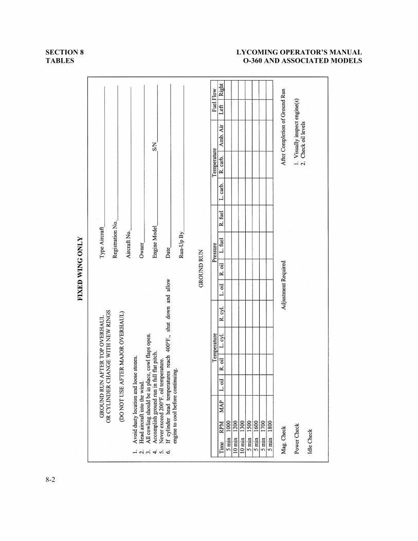
SECTION 8 LYCOMING OPERATOR’S MANUALTABLES O-360 AND ASSOCIATED MODELS
8-2
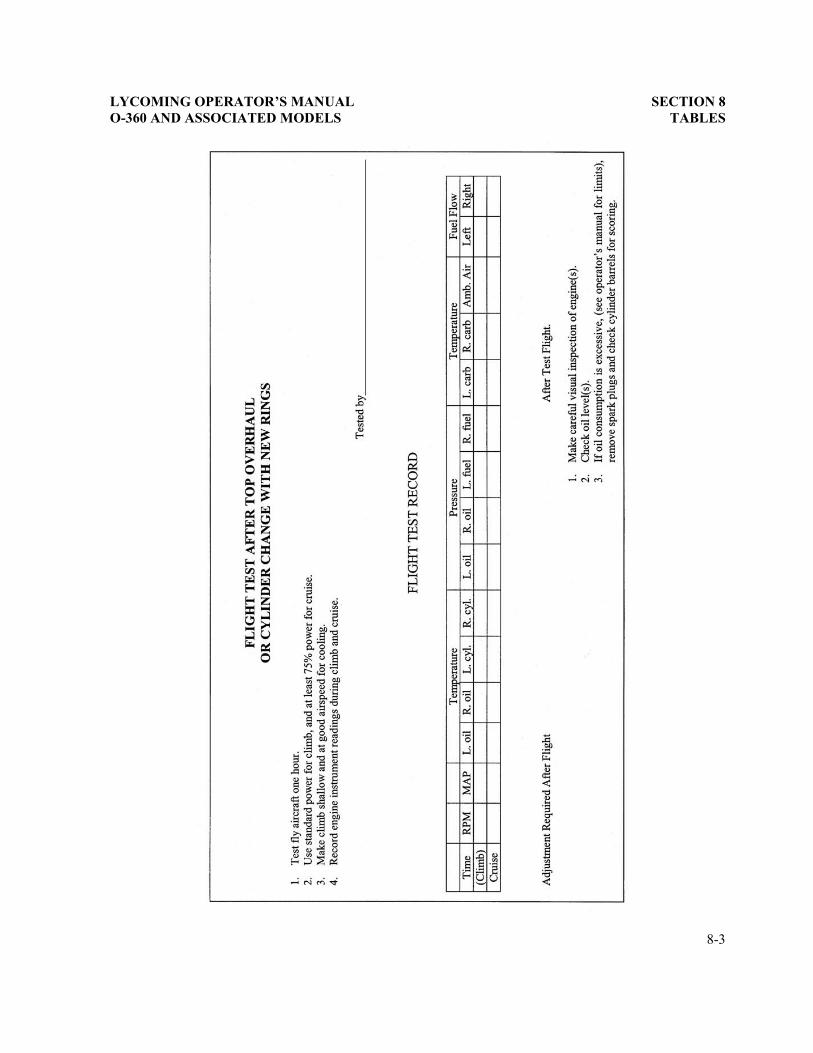
LYCOMING OPERATOR’S MANUAL SECTION 8O-360 AND ASSOCIATED MODELS TABLES
8-3
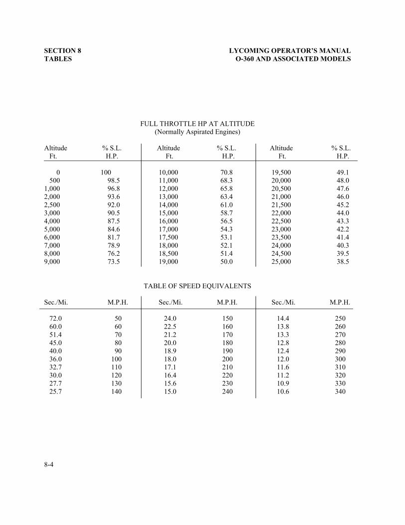
SECTION 8 LYCOMING OPERATOR’S MANUALTABLES O-360 AND ASSOCIATED MODELS
FULL THROTTLE HP AT ALTITUDE(Normally Aspirated Engines)
Altitude % S.L. Altitude % S.L. Altitude % S.L.Ft. H.P. Ft. H.P. Ft. H.P.
0 100 10,000 70.8 19,500 49.1500 98.5 11,000 68.3 20,000 48.01,000 96.8 12,000 65.8 20,500 47.62,000 93.6 13,000 63.4 21,000 46.02,500 92.0 14,000 61.0 21,500 45.23,000 90.5 15,000 58.7 22,000 44.04,000 87.5 16,000 56.5 22,500 43.35,000 84.6 17,000 54.3 23,000 42.26,000 81.7 17,500 53.1 23,500 41.47,000 78.9 18,000 52.1 24,000 40.38,000 76.2 18,500 51.4 24,500 39.59,000 73.5 19,000 50.0 25,000 38.5
TABLE OF SPEED EQUIVALENTS
Sec./Mi. M.P.H. Sec./Mi. M.P.H. Sec./Mi. M.P.H.
72.0 50 24.0 150 14.4 25060.0 60 22.5 160 13.8 26051.4 70 21.2 170 13.3 27045.0 80 20.0 180 12.8 28040.0 90 18.9 190 12.4 29036.0 100 18.0 200 12.0 30032.7 110 17.1 210 11.6 31030.0 120 16.4 220 11.2 32027.7 130 15.6 230 10.9 33025.7 140 15.0 240 10.6 340
8-4
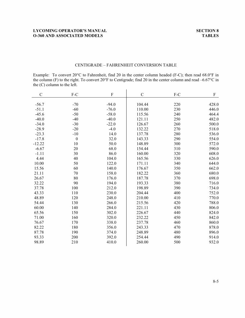
LYCOMING OPERATOR’S MANUAL SECTION 8O-360 AND ASSOCIATED MODELS TABLES
&(17,*5$'(�±�)$+5(1+(,7�&219(56,21�7$%/(�
Example: To convert 20°C to Fahrenheit, find 20 in the center column headed (F-C); then read 68.0°F inthe column (F) to the right. To convert 20°F to Centigrade; find 20 in the center column DQG�UHDG�±�����&�LQ�the (C) column to the left.
C F-C F C F-C F
-56.7 -70 -94.0 104.44 220 428.0-51.1 -60 -76.0 110.00 230 446.0-45.6 -50 -58.0 115.56 240 464.4-40.0 -40 -40.0 121.11 250 482.0-34.0 -30 -22.0 126.67 260 500.0-28.9 -20 -4.0 132.22 270 518.0-23.3 -10 14.0 137.78 280 536.0-17.8 0 32.0 143.33 290 554.0-12.22 10 50.0 148.89 300 572.0-6.67 20 68.0 154.44 310 590.0-1.11 30 86.0 160.00 320 608.04.44 40 104.0 165.56 330 626.010.00 50 122.0 171.11 340 644.015.56 60 140.0 176.67 350 662.021.11 70 158.0 182.22 360 680.026.67 80 176.0 187.78 370 698.032.22 90 194.0 193.33 380 716.037.78 100 212.0 198.89 390 734.043.33 110 230.0 204.44 400 752.048.89 120 248.0 210.00 410 770.054.44 130 266.0 215.56 420 788.060.00 140 284.0 221.11 430 806.065.56 150 302.0 226.67 440 824.071.00 160 320.0 232.22 450 842.076.67 170 338.0 237.78 460 860.082.22 180 356.0 243.33 470 878.087.78 190 374.0 248.89 480 896.093.33 200 392.0 254.44 490 914.098.89 210 410.0 260.00 500 932.0
8-5
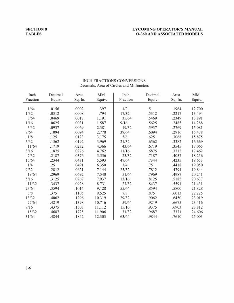
SECTION 8 LYCOMING OPERATOR’S MANUALTABLES O-360 AND ASSOCIATED MODELS
INCH FRACTIONS CONVERSIONSDecimals, Area of Circles and Millimeters
Inch Decimal Area MM Inch Decimal Area MMFraction Equiv. Sq. In. Equiv. Fraction Equiv. Sq. In. Equiv.
1/64 .0156 .0002 .397 1/2 .5 .1964 12.7001/32 .0312 .0008 .794 17/32 .5312 .2217 13.4943/64 .0469 .0017 1.191 35/64 .5469 .2349 13.8911/16 .0625 .0031 1.587 9/16 .5625 .2485 14.2883/32 .0937 .0069 2.381 19/32 .5937 .2769 15.0817/64 .1094 .0094 2.778 39/64 .6094 .2916 15.4781/8 .125 .0123 3.175 5/8 .625 .3068 15.8755/32 .1562 .0192 3.969 21/32 .6562 .3382 16.66911/64 .1719 .0232 4.366 43/64 .6719 .3545 17.0653/16 .1875 .0276 4.762 11/16 .6875 .3712 17.4627/32 .2187 .0376 5.556 23/32 .7187 .4057 18.25615/64 .2344 .0431 5.593 47/64 .7344 .4235 18.6531/4 .25 .0491 6.350 3/4 .75 .4418 19.0509/32 .2812 .0621 7.144 25/32 .7812 .4794 19.84419/64 .2969 .0692 7.540 51/64 .7969 .4987 20.2415/16 .3125 .0767 7.937 13/16 .8125 .5185 20.63711/32 .3437 .0928 8.731 27/32 .8437 .5591 21.43123/64 .3594 .1014 9.128 55/64 .8594 .5800 21.8283/8 .375 .1105 9.525 7/8 .875 .6013 22.22513/32 .4062 .1296 10.319 29/32 .9062 .6450 23.01927/64 .4219 .1398 10.716 59/64 .9219 .6675 23.4167/16 .4375 .1503 11.112 15/16 .9375 .6903 23.81215/32 .4687 .1725 11.906 31/32 .9687 .7371 24.60631/64 .4844 .1842 12.303 63/64 .9844 .7610 25.003
8-6


![FP-AIO-610 and cFP-AIO-610 Operating Instructions ... the user manual for the FieldPoint network module you are ... Input Circuitry on One Channel of the [c]FP-AIO-610 ... FP-AIO-610](https://static.fdocuments.us/doc/165x107/5b46f8f17f8b9a501f8c819a/fp-aio-610-and-cfp-aio-610-operating-instructions-the-user-manual-for-the-fieldpoint.jpg)