NZ1-10526613-Seismic Assessment of 91 Willow Street Campus ...
106
Report Seismic Assessment of 91 Willow Street Campus Buildings Prepared for Tauranga City Council Prepared by Beca Ltd (Beca) 25 May 2015
Transcript of NZ1-10526613-Seismic Assessment of 91 Willow Street Campus ...

Report
Seismic Assessment of 91 Willow Street Campus Buildings
Prepared for Tauranga City Council
Prepared by Beca Ltd (Beca)
25 May 2015


Seismic Assessment of 91 Willow Street Campus Buildings
Beca // 25 May 2015 2645270 // NZ1-10526613-12 0.12 // i
Contents
1 Introduction ........................................................................................................ 1
2 Scope of Services .............................................................................................. 2
3 Investigations and Findings ............................................................................. 4
4 Conclusions and Next Steps .......................................................................... 10
Appendices
Appendix A Library Building – Confirmation of Strengthening
Appendix B Seismic Assessment – Willow Street Campus – Building A & C
Appendix C Plan of Opus Test Locations
Appendix D Results Summary Plan

Beca // 25 May 2015 2645270 // NZ1-10526613-12 0.12 // page 1
1 Introduction
The purpose of this report is to summarise the outcome of seismic assessment work that Beca has completed for the four Tauranga City Council (TCC) campus buildings located at 91 Willow Street, Tauranga. And provide remedial solutions to lift the building seismic ratings above TCC’s target level of 67%NBS in terms of the performance for life safety, as determined using the New Zealand Society of Earthquake Engineering (NZSEE) guidelines. The campus buildings are identified as follows:
� Block A - Council Offices and Council Chambers � Block B (Library) - Council Offices and Customer Services � Block C - Council Offices and Public Library � Administration - Offices and Customer Services (currently not in use)
Beca has previously completed seismic assessment work for Block B and Administration buildings for TCC. Subsequently, Opus International Consultants Limited completed geotechnical investigations and assessment work for this site. This report summarises the findings of our further assessment of these buildings to assess the soils class and the likely effects liquefaction, based on the investigation work completed by Opus.
Beca has recently completed a detailed seismic assessment of Block A and C buildings. This report also summarises the outcome of this assessment work.

Beca // 25 May 2015 2645270 // NZ1-10526613-12 0.12 // page 2
2 Scope of Services
Beca’s scope of work is as below:
a. Geotechnical interpretation of CPT data provided by TCC to assess the soils class and the likely effects of liquefaction on all buildings for 1 in 500 year return period earthquake shaking. Provide inputs to mitigate these effects in the costing of remedial conceptual designs referred below.
b. Independent seismic assessment for Blocks A and C as per the scope below:
i. Review structural drawings provided by TCC.
ii. Visit the site and assess if the building structure is generally as per the drawings.
iii. Carry out engineering calculations to estimate the seismic capacity of the existing building, the building drawings and any other available information. The detailed assessment will be carried out in accordance with the recommendations of the New Zealand Society for Earthquake Engineering guidelines for assessing existing buildings. The assessment will consider the effect for any liquefaction expected for 1 in 500 year return period earthquake shaking on the structural system.
iv. Assess whether the building is an earthquake-prone building, [ie achieves less than 34% of the required standard of a new building (<34%NBS)].
v. Assess whether the building is an earthquake risk (ie achieves less than 67%NBS).
vi. Comment on the performance of the stairs and any recommended remediation.
vii. Report on assessment findings and (if required) remedial concepts to strengthen these buildings to 67%NBS for IL2 (including stairs), estimated construction timeframes and construction cost estimates to an accuracy of -+15%. The report will include a commentary on construction methodology of any remedial measures required.
c. Seismic Assessment of Glazing Systems
i. Estimate building movements for seismic shaking at 34% and 67% ULS levels (Ultimate Limit State as defined by NZS1170.5).
ii. Visit the site and assess the type of glazing systems, their movement capability and their ability to sustain the movements required.
iii. Assess and report on the life safety risk of the glazing systems resulting from building movement during a seismic event.
d. Carry out following scope on Block B:
i. Review structural calculations for alterations completed in 2006 for Block B and assess the %NBS
rating. The assessment will consider the effect of any liquefaction expected in 1 in 500 year return period earthquake shaking on the structural system.
ii. Review structural drawings provided by TCC.

Beca // 25 May 2015 2645270 // NZ1-10526613-12 0.12 // page 3
iii. Visit the site and assess if the building structure is generally as per the drawings and whether the previously recommended remediation works have been carried out.
iv. Report on assessment findings and (if required) provide remedial concepts to strengthen this buildings to 67%NBS for IL2 (including stairs), estimated construction timeframes and construction cost estimates to an accuracy of -+15%. We will include commentary on methodology. The report will include commentary on construction methodology of any remedial measures if required.
e. Carry out the following scope for the Administration building:
i. Provide confirmation of the current %NBS rating of the Administration building at 91 Willow Street following the plant room strengthening works carried out in 2012.
ii. Revise the concept for strengthening the Administration building to 67%NBS for Importance Level 2 accounting for the effects of any liquefaction expected in 1 in 500 year return period earthquake shaking.
iii. Provide construction cost estimates for retrofit strengthening to an accuracy of +-15%. Our cost estimation will consider the work required from a bare structure. We understand that the cost of removal of non-structural elements would be included as part of repairs related to weather tightness issues. The report will include a commentary on the construction methodology and estimated construction timeframes.
iv. Comment on the performance of the stairs and any recommended remediation.
Beca // 25 May 2015 2645270 // NZ1-10526613-12 0.12 // page 4
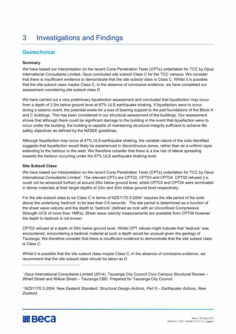
3 Investigations and Findings
Geotechnical
Summary
We have based our interpretation on the recent Cone Penetration Tests (CPTs) undertaken for TCC by Opus International Consultants Limited. Opus concluded site subsoil Class C for the TCC campus. We consider that there is insufficient evidence to demonstrate that the site subsoil class is Class C. Whilst it is possible that the site subsoil class maybe Class C, in the absence of conclusive evidence, we have completed our assessment considering site subsoil class D.
We have carried out a very preliminary liquefaction assessment and concluded that liquefaction may occur from a depth of 2.5m below ground level at 67% ULS earthquake shaking. If liquefaction were to occur during a seismic event, the potential exists for a loss of bearing support to the pad foundations of the Block A and C buildings. This has been considered in our structural assessment of the buildings. Our assessment shows that although there could be significant damage to the building in the event that liquefaction were to occur under the building, the building is capable of maintaining structural integrity sufficient to achieve life safety objectives as defined by the NZSEE guidelines.
Although liquefaction may occur at 67% ULS earthquake shaking, the variable nature of the soils identified suggests that liquefaction would likely be experienced in discontinuous zones, rather than as a uniform layer extending to the harbour to the west. We therefore consider that there is a low risk of lateral spreading towards the harbour occurring under the 67% ULS earthquake shaking level.
Site Subsoil Class
We have based our interpretation on the recent Cone Penetration Tests (CPTs) undertaken for TCC by Opus International Consultants Limited1. The relevant CPTs are CPT02, CPT03 and CPT04. CPT02 refused (i.e. could not be advanced further) at around 20m below ground level, whilst CPT03 and CPT04 were terminated in dense materials at their target depths of 22m and 20m below ground level respectively.
For the site subsoil class to be Class C in terms of NZS1170.5:20042 requires the site period of the soils above the underlying ‘bedrock’ to be less than 0.6 seconds. The site period is determined as a function of the shear wave velocity and the depth to ‘bedrock’ (defined as rock with an Unconfined Compressive Strength UCS of more than 1MPa). Shear wave velocity measurements are available from CPT04 however the depth to bedrock is not known.
CPT02 refused at a depth of 20m below ground level. Whilst CPT refusal might indicate that ‘bedrock’ was encountered, encountering a bedrock material at such a depth would be unusual given the geology of Tauranga. We therefore consider that there is insufficient evidence to demonstrate that the site subsoil class is Class C.
Whilst it is possible that the site subsoil class maybe Class C, in the absence of conclusive evidence, we recommend that the site subsoil class should be taken as D.
1 Opus International Consultants Limited (2014). Tauranga City Council Civic Campus Structural Review – Wharf Street and Willow Street – Tauranga CBD. Prepared for Tauranga City Council.
2 NZS1170.5.2004: New Zealand Standard: Structural Design Actions, Part 5 – Earthquake Actions, New
Zealand
Beca // 25 May 2015 2645270 // NZ1-10526613-12 0.12 // page 5
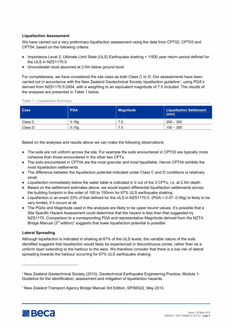
Liquefaction Assessment
We have carried out a very preliminary liquefaction assessment using the data from CPT02, CPT03 and CPT04, based on the following criteria:
� Importance Level 2, Ultimate Limit State (ULS) Earthquake shaking = 1/500 year return period defined for the ULS in NZS1170.5.
� Groundwater level assumed at 2.5m below ground level
For completeness, we have considered the site class as both Class C or D. Our assessments have been carried out in accordance with the New Zealand Geotechnical Society liquefaction guideline3, using PGA’s derived from NZS1170.5:2004, with a weighting to an equivalent magnitude of 7.5 included. The results of the analyses are presented in Table 1 below.
Table 1 - Liquefaction Summary
Case PGA Magnitude Liquefaction Settlement (mm)
Class C 0.18g 7.5 200 – 300 Class D 0.15g 7.5 150 – 300
Based on the analyses and results above we can make the following observations:
� The soils are not uniform across the site. For example the soils encountered in CPT03 are typically more cohesive than those encountered in the other two CPTs.
� The soils encountered in CPT04 are the most granular and most liquefiable. Hence CPT04 exhibits the most liquefaction settlements.
� The difference between the liquefaction potential indicated under Class C and D conditions is relatively small.
� Liquefaction immediately below the water table is indicated in 2 out of the 3 CPTs, i.e. at 2.5m depth. � Based on the settlement estimates above, we would expect differential liquefaction settlements across
the building footprint in the order of 100 to 150mm for 67% ULS earthquake shaking. � Liquefaction in an event 33% of that defined for the ULS in NZS1170.5. (PGA = 0.07-.0.09g) is likely to be
very limited, if it occurs at all. � The PGAs and Magnitude used in the analyses are likely to be upper bound values. It’s possible that a
Site Specific Hazard Assessment could determine that the hazard is less than that suggested by NZS1170. Comparison to a corresponding PGA and representative Magnitude derived from the NZTA Bridge Manual (3rd edition)4 suggests that lower liquefaction potential is possible.
Lateral Spreading
Although liquefaction is indicated in shaking at 67% of the ULS levels, the variable nature of the soils identified suggests that liquefaction would likely be experienced in discontinuous zones, rather than as a uniform layer extending to the harbour to the west. We therefore consider that there is a low risk of lateral spreading towards the harbour occurring for 67% ULS earthquake shaking.
3 New Zealand Geotechnical Society (2010). Geotechnical Earthquake Engineering Practice, Module 1-Guideline for the identification, assessment and mitigation of liquefaction hazards.
4 New Zealand Transport Agency Bridge Manual 3rd Edition, SP/M/022, May 2013.

Beca // 25 May 2015 2645270 // NZ1-10526613-12 0.12 // page 6
Bearing Capacity
Liquefaction is indicated from a depth of 2.5m below ground level. We understand that the buildings’ foundations are typically founded at a depth of around 1.0 to 1.5m below ground level. If liquefaction were to occur during a seismic event, then the potential exists for larger strains to be experienced under some foundations as a result of a loss of bearing support from the liquefied soils.
The Administration building foundations are strip footings founded at around 1.5m below ground level. We note that the basement level around the stair lift shaft lies at around 2.5m below ground level, so could be directly bearing onto potentially liquefiable soils. This zone is the most likely to experience a loss of bearing support.
By contrast buildings A and C are founded on pad foundations founded at around 1.5m below ground level.
The consequence of a loss of bearing support under some foundations has been considered in the structural seismic assessments, see below.
Seismic Assessment of Glazing Systems
TCC requested a seismic assessment of the glazing systems for the TCC Willow St Campus buildings. Beca engaged glazing façade specialists, Thermosash Commercial Ltd to carry out this work because we do not have suitable expertise or experience for assessment of glazing façades.
Thermosash carried out a limited visual inspection and assessment of the campus buildings glazing systems. Their assessment report is included as part of the seismic assessment work completed for Block A and C buildings (refer Appendix B). Thermosash’s assessment concluded that glazing in the Atrium area and street canopies is likely to be vulnerable to earthquake shaking and has the potential to pose a significant risk to the public/employees in the Atrium and street frontage areas during a seismic event.
We note that Beca have not identified, and therefore not contacted, the original designers, fabricators or installers of the glazing system for these buildings. We recommend that an attempt is made to locate and notify the original companies involved with design, fabrication or installation of the glazing systems before carrying out remedial work.
Blocks A & C – Offices and Customer Services
Introduction
We have carried out a detailed seismic assessment of building Blocks A and C. Details on this assessment are provided in our report titled Seismic Assessment – Willow Street Campus Buildings A and C, dated 20 March 2015 (refer Appendix B). Below is a summary from this report.
The original lower two storeys of Block A and C consist of reinforced concrete framed structures with Uni-slab concrete flooring, constructed circa 1987. The roofs were originally used as a car park prior to the construction of a steel framed second storey on both buildings circa 2003.
The primary lateral load resisting system of the original structures is reinforced concrete moment frames on shallow concrete foundations. The lateral loads in the top floor additions are resisted by plywood and plasterboard lined timber walls and steel portals. Roof bracing consists of a plywood roof diaphragm in Block A and steel roof bracing in Block C.
There are concrete slab pedestrian bridges at the first and second floor levels spanning between Blocks A, B, C, and Admin building. The Atrium areas between Block A, B and C buildings are covered at roof level
Beca // 25 May 2015 2645270 // NZ1-10526613-12 0.12 // page 7
with a mixed glazing/cladding system. A glazed canopy over the footpath on Willow and Wharf Streets is supported off Block A and C buildings.
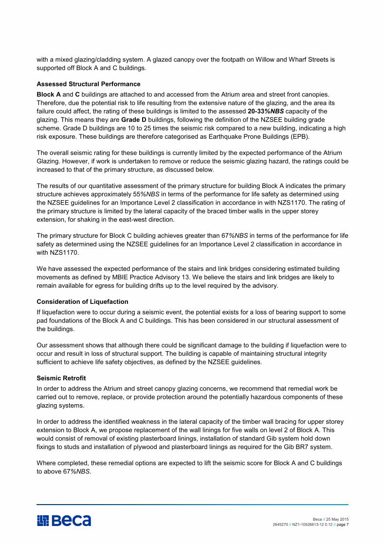
Assessed Structural Performance
Block A and C buildings are attached to and accessed from the Atrium area and street front canopies. Therefore, due the potential risk to life resulting from the extensive nature of the glazing, and the area its failure could affect, the rating of these buildings is limited to the assessed 20-33%NBS capacity of the glazing. This means they are Grade D buildings, following the definition of the NZSEE building grade scheme. Grade D buildings are 10 to 25 times the seismic risk compared to a new building, indicating a high risk exposure. These buildings are therefore categorised as Earthquake Prone Buildings (EPB).
The overall seismic rating for these buildings is currently limited by the expected performance of the Atrium Glazing. However, if work is undertaken to remove or reduce the seismic glazing hazard, the ratings could be increased to that of the primary structure, as discussed below.
The results of our quantitative assessment of the primary structure for building Block A indicates the primary structure achieves approximately 55%NBS in terms of the performance for life safety as determined using the NZSEE guidelines for an Importance Level 2 classification in accordance in with NZS1170. The rating of the primary structure is limited by the lateral capacity of the braced timber walls in the upper storey extension, for shaking in the east-west direction.
The primary structure for Block C building achieves greater than 67%NBS in terms of the performance for life safety as determined using the NZSEE guidelines for an Importance Level 2 classification in accordance in with NZS1170.
We have assessed the expected performance of the stairs and link bridges considering estimated building movements as defined by MBIE Practice Advisory 13. We believe the stairs and link bridges are likely to remain available for egress for building drifts up to the level required by the advisory.
Consideration of Liquefaction
If liquefaction were to occur during a seismic event, the potential exists for a loss of bearing support to some pad foundations of the Block A and C buildings. This has been considered in our structural assessment of the buildings.
Our assessment shows that although there could be significant damage to the building if liquefaction were to occur and result in loss of structural support. The building is capable of maintaining structural integrity sufficient to achieve life safety objectives, as defined by the NZSEE guidelines.
Seismic Retrofit
In order to address the Atrium and street canopy glazing concerns, we recommend that remedial work be carried out to remove, replace, or provide protection around the potentially hazardous components of these glazing systems.
In order to address the identified weakness in the lateral capacity of the timber wall bracing for upper storey extension to Block A, we propose replacement of the wall linings for five walls on level 2 of Block A. This would consist of removal of existing plasterboard linings, installation of standard Gib system hold down fixings to studs and installation of plywood and plasterboard linings as required for the Gib BR7 system.
Where completed, these remedial options are expected to lift the seismic score for Block A and C buildings to above 67%NBS.
Beca // 25 May 2015 2645270 // NZ1-10526613-12 0.12 // page 8
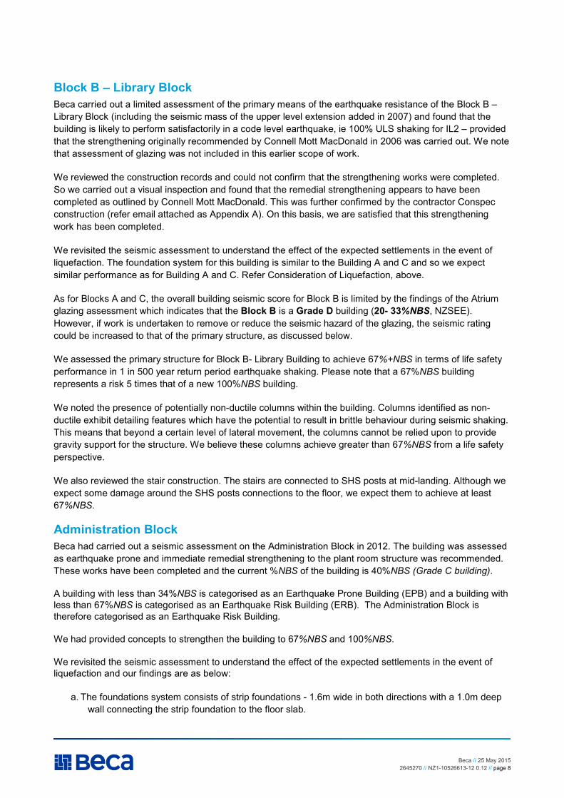
Block B – Library Block
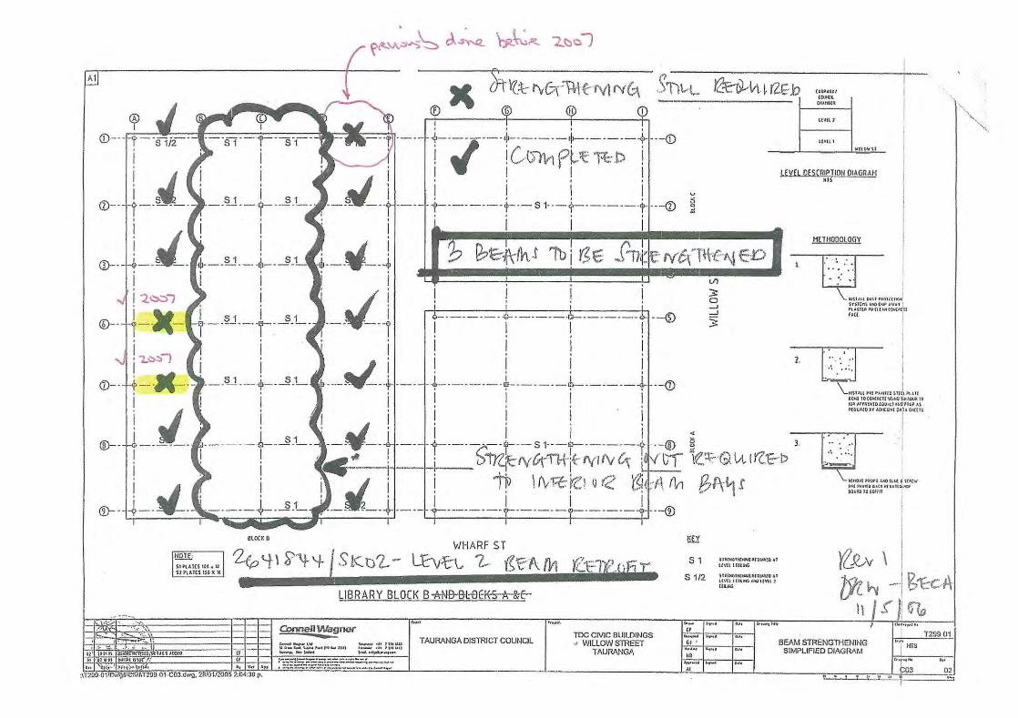
Beca carried out a limited assessment of the primary means of the earthquake resistance of the Block B – Library Block (including the seismic mass of the upper level extension added in 2007) and found that the building is likely to perform satisfactorily in a code level earthquake, ie 100% ULS shaking for IL2 – provided that the strengthening originally recommended by Connell Mott MacDonald in 2006 was carried out. We note that assessment of glazing was not included in this earlier scope of work.
We reviewed the construction records and could not confirm that the strengthening works were completed. So we carried out a visual inspection and found that the remedial strengthening appears to have been completed as outlined by Connell Mott MacDonald. This was further confirmed by the contractor Conspec construction (refer email attached as Appendix A). On this basis, we are satisfied that this strengthening work has been completed.
We revisited the seismic assessment to understand the effect of the expected settlements in the event of liquefaction. The foundation system for this building is similar to the Building A and C and so we expect similar performance as for Building A and C. Refer Consideration of Liquefaction, above.
As for Blocks A and C, the overall building seismic score for Block B is limited by the findings of the Atrium glazing assessment which indicates that the Block B is a Grade D building (20- 33%NBS, NZSEE). However, if work is undertaken to remove or reduce the seismic hazard of the glazing, the seismic rating could be increased to that of the primary structure, as discussed below.
We assessed the primary structure for Block B- Library Building to achieve 67%+NBS in terms of life safety performance in 1 in 500 year return period earthquake shaking. Please note that a 67%NBS building represents a risk 5 times that of a new 100%NBS building.
We noted the presence of potentially non-ductile columns within the building. Columns identified as non-ductile exhibit detailing features which have the potential to result in brittle behaviour during seismic shaking. This means that beyond a certain level of lateral movement, the columns cannot be relied upon to provide gravity support for the structure. We believe these columns achieve greater than 67%NBS from a life safety perspective.
We also reviewed the stair construction. The stairs are connected to SHS posts at mid-landing. Although we expect some damage around the SHS posts connections to the floor, we expect them to achieve at least 67%NBS.
Administration Block
Beca had carried out a seismic assessment on the Administration Block in 2012. The building was assessed as earthquake prone and immediate remedial strengthening to the plant room structure was recommended. These works have been completed and the current %NBS of the building is 40%NBS (Grade C building).
A building with less than 34%NBS is categorised as an Earthquake Prone Building (EPB) and a building with less than 67%NBS is categorised as an Earthquake Risk Building (ERB). The Administration Block is therefore categorised as an Earthquake Risk Building.
We had provided concepts to strengthen the building to 67%NBS and 100%NBS.
We revisited the seismic assessment to understand the effect of the expected settlements in the event of liquefaction and our findings are as below:
a. The foundations system consists of strip foundations - 1.6m wide in both directions with a 1.0m deep wall connecting the strip foundation to the floor slab.

Beca // 25 May 2015 2645270 // NZ1-10526613-12 0.12 // page 9
b. There is approximately 1.0m of soil crust between the u/s of the foundations and the layer of the soil expected to liquefy.
We expect the foundation raft described above and the soil crust combined with the structural system of the building to be able to withstand the expected settlement due to liquefaction without causing collapse. However we do expect some damage.
Based on our findings above, the concept proposed to strengthen the building to 67%NBS in our previous assessment remains unchanged.
This option consists of new shear walls, some strengthening to columns and new foundations. No work is required to the stairs to meet 67%NBS.
Beca // 25 May 2015 2645270 // NZ1-10526613-12 0.12 // page 10
4 Conclusions and Next Steps
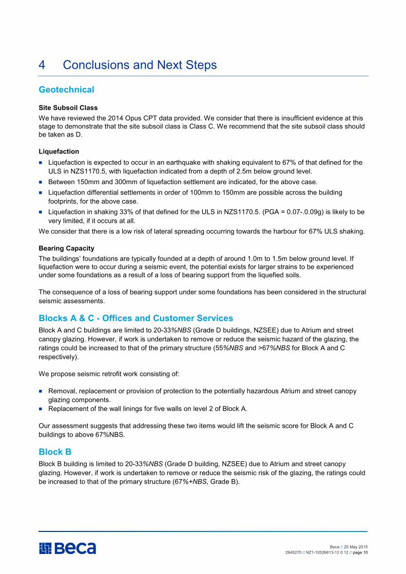
Geotechnical
Site Subsoil Class
We have reviewed the 2014 Opus CPT data provided. We consider that there is insufficient evidence at this stage to demonstrate that the site subsoil class is Class C. We recommend that the site subsoil class should be taken as D.
Liquefaction
� Liquefaction is expected to occur in an earthquake with shaking equivalent to 67% of that defined for the ULS in NZS1170.5, with liquefaction indicated from a depth of 2.5m below ground level.
� Between 150mm and 300mm of liquefaction settlement are indicated, for the above case. � Liquefaction differential settlements in order of 100mm to 150mm are possible across the building
footprints, for the above case. � Liquefaction in shaking 33% of that defined for the ULS in NZS1170.5. (PGA = 0.07-.0.09g) is likely to be
very limited, if it occurs at all. We consider that there is a low risk of lateral spreading occurring towards the harbour for 67% ULS shaking.
Bearing Capacity
The buildings’ foundations are typically founded at a depth of around 1.0m to 1.5m below ground level. If liquefaction were to occur during a seismic event, the potential exists for larger strains to be experienced under some foundations as a result of a loss of bearing support from the liquefied soils.
The consequence of a loss of bearing support under some foundations has been considered in the structural seismic assessments.
Blocks A & C - Offices and Customer Services
Block A and C buildings are limited to 20-33%NBS (Grade D buildings, NZSEE) due to Atrium and street canopy glazing. However, if work is undertaken to remove or reduce the seismic hazard of the glazing, the ratings could be increased to that of the primary structure (55%NBS and >67%NBS for Block A and C respectively).
We propose seismic retrofit work consisting of:
� Removal, replacement or provision of protection to the potentially hazardous Atrium and street canopy glazing components.
� Replacement of the wall linings for five walls on level 2 of Block A.
Our assessment suggests that addressing these two items would lift the seismic score for Block A and C buildings to above 67%NBS.
Block B
Block B building is limited to 20-33%NBS (Grade D building, NZSEE) due to Atrium and street canopy glazing. However, if work is undertaken to remove or reduce the seismic risk of the glazing, the ratings could be increased to that of the primary structure (67%+NBS, Grade B).

Beca // 25 May 2015 2645270 // NZ1-10526613-12 0.12 // page 11
Administration Block
We assessed the Administration Building (accounting for the expected liquefaction settlements) to achieve 40%+NBS in terms of life safety performance in 1 in 500 year return period earthquake shaking.
A building with less than 34%NBS is categorised as an Earthquake Prone Building (EPB) and a building with less than 67%NBS is categorised as an Earthquake Risk Building (ERB). The Administration Block B is therefore considered to be an earthquake-risk building and is a Grade C building.
We recommend strengthening to 67%NBS in conjunction with the repair works intended to be carried out to fix the water tightness issues.
Refer Appendix D – overall site plan showing current scores for each building.

Beca // 25 May 2015 2645270 // NZ1-10526613-12 0.12 // page 12
Appendix A
Library Building – Confirmation of Strengthening


Beca // 25 May 2015 2645270 // NZ1-10526613-12 0.12 // page 13
Appendix B
Seismic Assessment – Willow Street Campus – Building A & C

Report
Seismic Assessment - Willow Street Campus - Building A & C
Prepared for Tauranga City Council
Prepared by Beca Ltd (Beca)
25 May 2015


Seismic Assessment - Willow Street Campus - Building A & C
Beca // 25 May 2015 2645270 // NZ1-10440281-15 0.15 // ii
Executive Summary Background
This seismic assessment report has been prepared for Tauranga City Council (TCC) to describe the results of our quantitative assessment of Blocks A and C buildings at 91 Willow Street, Tauranga (TCC are the owners of these buildings). And provide remedial solutions to lift the building seismic ratings above TCC’s target level of 67%NBS in terms of the performance for life safety, as determined using the New Zealand Society of Earthquake Engineering (NZSEE) guidelines. This follows separate detailed seismic assessments carried out by OPUS for Blocks A, B and C dated May 2014. This report has been prepared in accordance with the scope of work described in the proposal dated 16 February 2015.
Description of Buildings
The TCC campus at 91 Willow Street consists of three buildings of similar design (Blocks A, B and C) designed and constructed circa 1987. The buildings were likely to have been designed to the loadings standard NZS4203:1984 and concrete standard NZS3101:1982. The primary use of Blocks A and C is office space with some retail areas on the ground floor.
The original lower two storeys of Block A and C consist of reinforced concrete framed structures with Uni-slab concrete flooring. The roofs were originally used as a car park prior to the construction of a steel framed second storey on both buildings circa 2003.
The primary lateral load resisting system of the original structures is reinforced concrete moment frames on shallow concrete foundations. The lateral loads in the top floor additions are resisted by plywood and plasterboard lined timber walls and steel portals. Roof bracing consists of a plywood roof diaphragm in Block A and steel roof bracing in Block C.
The area between Block A, B and C buildings is enclosed by a glazed Atrium. Structural steel beams span between the buildings to support the roof and end wall glazing. There is also a glazed canopy above the sidewalk on Willow and Wharf Street. The canopy is supported off Block A and C buildings.
There are concrete slab pedestrian bridges at the first and second floor levels spanning between Blocks A, B, C, and Admin buildings.
There are plant platforms on the roof of both Blocks A and C.
Geotechnical Considerations
We have based our interpretation on the recent Cone Penetration Tests (CPTs) undertaken for TCC by Opus International Consultants Limited. Opus concluded site subsoil Class C for the TCC campus. We consider that there is insufficient evidence to demonstrate that the site subsoil class is Class C. Whilst it is possible that the site subsoil class maybe Class C, in the absence of conclusive evidence, we have completed our assessment considering site subsoil class D.
We have carried out a very preliminary liquefaction assessment and concluded that liquefaction may occur from a depth of 2.5m below ground level at 67% ULS earthquake shaking. If liquefaction were to occur during a seismic event, the potential exists for a loss of bearing support to the pad foundations of the Block A and C buildings. This has been considered in our structural assessment of the buildings. Our assessment shows that although there could be significant damage to the building in the event that liquefaction were to occur under the building, the building is capable of maintaining structural integrity sufficient to achieve life safety objectives as defined by the NZSEE guidelines.

Seismic Assessment - Willow Street Campus - Building A & C
Beca // 25 May 2015 2645270 // NZ1-10440281-15 0.15 // iii
Although liquefaction may occur at 67% ULS earthquake shaking, the variable nature of the soils identified suggests that liquefaction would likely be experienced in discontinuous zones, rather than as a uniform layer extending to the harbour to the west. We therefore consider that there is a low risk of lateral spreading towards the harbour occurring under the 67% ULS earthquake shaking level.
Seismic Assessment of Glazing Systems
TCC requested a seismic assessment of the glazing systems for the TCC Willow St Campus buildings. Beca engaged glazing façade specialists, Thermosash Commercial Ltd to carry out this work because we do not have suitable expertise or experience for assessment of glazing façades.
Thermosash carried out a limited visual inspection and assessment of the campus buildings glazing systems. Their assessment concluded that glazing in the Atrium area and street canopies is likely to be vulnerable to earthquake shaking and has the potential to pose a significant risk to the public/employees in the Atrium and street frontage areas during a seismic event.
Assessed Building Seismic Performance
Block A and C buildings are attached to and accessed from the Atrium area and street front canopies. Therefore, due the potential risk to life resulting from the extensive nature of the glazing, and the area its failure could affect, the rating of these buildings is limited to the assessed 20-33%NBS capacity of the glazing. This means they are Grade D buildings, following the definition of the NZSEE building grade scheme. Grade D buildings are 10 to 25 times the seismic risk compared to a new building, indicating a high risk exposure. These buildings are therefore categorised as Earthquake Prone Buildings (EPB).
The overall seismic rating for these buildings is currently limited by the expected performance of the Atrium Glazing. However, if work is undertaken to remove or reduce the seismic glazing hazard, the ratings could be increased to that of the primary structure, as discussed below.
The results of our quantitative assessment of the primary structure for building Block A indicates the primary structure achieves approximately 55%NBS in terms of the performance for life safety as determined using the NZSEE guidelines for an Importance Level 2 classification in accordance in with NZS1170. The rating of the primary structure is limited by the lateral capacity of the braced timber walls in the upper storey extension, for shaking in the east-west direction.
The primary structure for Block C building achieves greater than 67%NBS in terms of the performance for life safety as determined using the NZSEE guidelines for an Importance Level 2 classification in accordance in with NZS1170.
Our assessment identified the following weaknesses in the primary structure which, combined with the Atrium glazing, govern the seismic performance:
� The available/calculated lateral capacity of the timber wall bracing for the upper storey extension to Block A limits the seismic building score to less than 67%NBS for shaking in the east-west direction.
In addition to our findings for the primary structure noted above, the expected performance of the site and following selected secondary elements have also been assessed:
� Glazing: Potential risk to public/staff from the Atrium and street canopy glazing, as discussed above. � Liquefaction: Our assessment shows that although there could be significant damage to the building in
the event that liquefaction were to occur under the building, the building is capable of maintaining structural integrity sufficient to achieve life safety objectives as defined by the NZSEE guidelines.

Seismic Assessment - Willow Street Campus - Building A & C
Beca // 25 May 2015 2645270 // NZ1-10440281-15 0.15 // iv
� Stairs: We have assessed the expected performance of the stairs considering estimated building movements as defined by Ministry of Business, Innovation, and Employment (MBIE) Practice Advisory 13. We believe the stairs are likely to remain available for egress for building drifts up to the level required by the advisory.
� Link bridges: We have assessed the expected performance of the link bridges based on the available details and considering estimated building movements. We consider that these can perform satisfactorily for scaled building drifts calculated to 67% ULS earthquake shaking. Calculated building drafts have been increased by a factor of two, as recommended by MBIE Practice Advisory 13.
Seismic Retrofit Options
In order to address the Atrium and street canopy glazing concerns, we recommend that remedial work be carried out to remove, replace, or provide protection around the potentially hazardous components of these glazing systems.
In order to address the identified weakness in the lateral capacity of the timber wall bracing for upper storey extension to Block A, we propose replacement of the wall linings for five walls on level 2 of Block A. This would consist of removal of existing plasterboard linings, installation of standard Gib system hold down fixings to studs and installation of plywood and plasterboard linings as required for the Gib BR7 system.
Where completed, these remedial options are expected to lift the seismic score for Block A and C buildings to above 67%NBS.
These concepts have been developed for discussion with TCC.
Next Steps
We recommend that TCC consider carrying out the following next steps:
� Carry out strengthening of the timber walls at level 2 of Block A. � Carry out remedial work to the Atrium and street canopy glazing.
Note: we recommend that an attempt is made to locate and notify the original companies involved with design, fabrication or installation of the glazing systems before carrying out remedial work.
Our assessment suggests that addressing these two items would lift the seismic score for Block A and C buildings to above 67%NBS.

Seismic Assessment - Willow Street Campus - Building A & C
Beca // 25 May 2015 2645270 // NZ1-10440281-15 0.15 // i
Contents
1 Introduction ........................................................................................................ 1 1.1 Scope of Assessment ...................................................................................................................... 1 1.2 Regulatory Environment and Design Standards ............................................................................. 1 1.3 Assessment Methodology ................................................................................................................ 2 1.4 Explanatory Statement .................................................................................................................... 3
2 Building Description .......................................................................................... 4 2.1 Building A & C .................................................................................................................................. 4 2.2 Site Conditions ................................................................................................................................. 6 2.3 Structural System ............................................................................................................................ 8
3 Results of Seismic Assessment..................................................................... 10 3.1 Seismic Assessment of Glazing Systems ..................................................................................... 10 3.2 Seismic Assessment of Structure .................................................................................................. 10
4 Commentary on Associated Seismic Risks .................................................. 12 4.1 Stairs .............................................................................................................................................. 12 4.2 Link Bridges ................................................................................................................................... 12 4.3 Liquefaction.................................................................................................................................... 13 4.4 Risks from Non-structural Building Elements ................................................................................ 13
5 Assessment of Seismic Risk .......................................................................... 14 5.1 Seismic Risk and Performance Levels .......................................................................................... 14
6 Seismic Retrofit and Strengthening ................................................................ 1 6.1 Retrofit and Strengthening Options ................................................................................................. 1 6.2 Preliminary Cost Estimate ............................................................................................................... 1
7 Next Steps .......................................................................................................... 2
Appendices
Appendix A Sources of Information
Appendix B Seismic Assessment Assumptions
Appendix C Building Inspection Photographs
Appendix D Structural Drawings
Seismic Assessment - Willow Street Campus - Building A & C
Beca // 25 May 2015 2645270 // NZ1-10440281-15 0.15 // ii
Appendix E Glazing Assessment – Letter from Thermosash
Appendix F Estimated Building Seismic Displacement
Seismic Assessment - Willow Street Campus - Building A & C
Beca // 25 May 2015 2645270 // NZ1-10440281-15 0.15 // page 1
1 Introduction
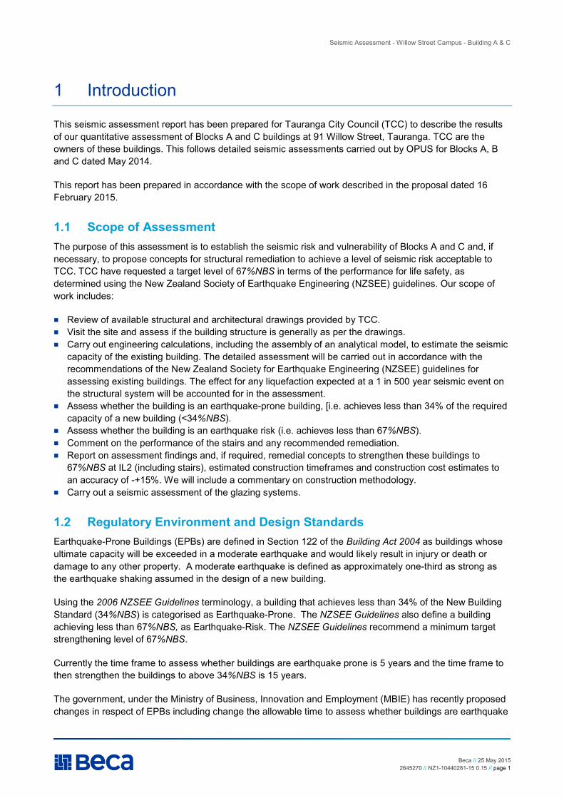
This seismic assessment report has been prepared for Tauranga City Council (TCC) to describe the results of our quantitative assessment of Blocks A and C buildings at 91 Willow Street, Tauranga. TCC are the owners of these buildings. This follows detailed seismic assessments carried out by OPUS for Blocks A, B and C dated May 2014.
This report has been prepared in accordance with the scope of work described in the proposal dated 16 February 2015.
1.1 Scope of Assessment
The purpose of this assessment is to establish the seismic risk and vulnerability of Blocks A and C and, if necessary, to propose concepts for structural remediation to achieve a level of seismic risk acceptable to TCC. TCC have requested a target level of 67%NBS in terms of the performance for life safety, as determined using the New Zealand Society of Earthquake Engineering (NZSEE) guidelines. Our scope of work includes:
� Review of available structural and architectural drawings provided by TCC. � Visit the site and assess if the building structure is generally as per the drawings. � Carry out engineering calculations, including the assembly of an analytical model, to estimate the seismic
capacity of the existing building. The detailed assessment will be carried out in accordance with the recommendations of the New Zealand Society for Earthquake Engineering (NZSEE) guidelines for assessing existing buildings. The effect for any liquefaction expected at a 1 in 500 year seismic event on the structural system will be accounted for in the assessment.
� Assess whether the building is an earthquake-prone building, [i.e. achieves less than 34% of the required capacity of a new building (<34%NBS).
� Assess whether the building is an earthquake risk (i.e. achieves less than 67%NBS). � Comment on the performance of the stairs and any recommended remediation. � Report on assessment findings and, if required, remedial concepts to strengthen these buildings to
67%NBS at IL2 (including stairs), estimated construction timeframes and construction cost estimates to an accuracy of -+15%. We will include a commentary on construction methodology.
� Carry out a seismic assessment of the glazing systems.
1.2 Regulatory Environment and Design Standards
Earthquake-Prone Buildings (EPBs) are defined in Section 122 of the Building Act 2004 as buildings whose ultimate capacity will be exceeded in a moderate earthquake and would likely result in injury or death or damage to any other property. A moderate earthquake is defined as approximately one-third as strong as the earthquake shaking assumed in the design of a new building.
Using the 2006 NZSEE Guidelines terminology, a building that achieves less than 34% of the New Building Standard (34%NBS) is categorised as Earthquake-Prone. The NZSEE Guidelines also define a building achieving less than 67%NBS, as Earthquake-Risk. The NZSEE Guidelines recommend a minimum target strengthening level of 67%NBS.
Currently the time frame to assess whether buildings are earthquake prone is 5 years and the time frame to then strengthen the buildings to above 34%NBS is 15 years.
The government, under the Ministry of Business, Innovation and Employment (MBIE) has recently proposed changes in respect of EPBs including change the allowable time to assess whether buildings are earthquake

Seismic Assessment - Willow Street Campus - Building A & C
Beca // 25 May 2015 2645270 // NZ1-10440281-15 0.15 // page 2
prone and then strengthen buildings to above 34%NBS. For buildings in Tauranga (other than schools and emergency facilities) the proposed time frame for assessment is 10 years and the proposed time frame for strengthening is 25 years. No change to the definition of an earthquake prone building has been proposed at this stage.
It is considered impractical and unaffordable to design every building to withstand the largest earthquake imaginable. Consequently, with respect to the determination of design loads for natural hazards, the New Zealand Loading Standard adopts a probabilistic approach that takes into account the exposure hazard at a given location, along with factors such as building importance. Thus, the Loading Standard may be said to adopt a risk management approach in setting the loading levels that a given building is required to withstand.
For normal use buildings (e.g. offices, apartments), the “design” earthquake load is set at the 1 in 500 year return period earthquake shaking level. This event has approximately a 10% probability of exceedence over the assumed 50 year life of a building.
1.3 Assessment Methodology
We have adopted a stepped analysis approach to undertaking the seismic assessment of the structure for Block A and C buildings. We started with simpler analysis methods and progressively employed more sophisticated methods of analysis and calculations in order to determine the seismic vulnerability of the building. The techniques used are generally as outlined in the June 2006 report by the New Zealand Society for Earthquake Engineering entitled Assessment and Improvement of the Structural Performance of
Buildings in Earthquakes (2006 NZSEE Guidelines).
Our methodology is briefly summarised below:
� Review of the available structural and architectural drawings and any calculations available to us (provided by TCC).
� Identify the main structural elements and any apparent “structural weaknesses” that may significantly reduce the seismic performance of the building to the point that it would become a risk to life safety. The critical structural weakness is the structural weakness determined to have the lowest score.
� Visual inspection of key elements of the building including the pedestrian bridges spanning between Blocks A, C, Block B and Admin building; the columns and beams of the reinforced concrete levels of the buildings; and the low level walls between the columns in the South West corner of Block A.
� Calculation of the expected seismic loads on the building following the current New Zealand loading standards (NZS1170).
� Hand analysis of selected critical elements of the building to determine the likely failure mechanisms of these subassemblies, and the whole building.
� Development of an elastic three-dimensional (3D) ETABS computer model of Block A building for analysis of the force distributions and critical structural elements using the NZ loading code response spectrum.
� Block A and C buildings are considered vertically irregular due to the variation in weight and lateral stiffness between the lower concrete structure and steel upper structure. The resulting amplification on seismic accelerations for the upper storeys have been considered in our assessment.
� Development of a Spacegass model of the stair assembly and an analysis of the assembly based on the drifts obtained from the building analysis to review expected performance of the stairs under seismic loading.
� Review of link bridge performance based on drifts obtained from the building analysis and detailing from council archive drawings.
Seismic Assessment - Willow Street Campus - Building A & C
Beca // 25 May 2015 2645270 // NZ1-10440281-15 0.15 // page 3
� Determination of the likely seismic performance of the building compared with an equivalent new building at the site based on our inspections, the structural weaknesses identified, our calculations, and our engineering judgment.
1.4 Explanatory Statement
� This report has been prepared by Beca at the request of our Client and is exclusively for our Client’s use for the purpose for which it is intended in accordance with the agreed scope of work. Beca accepts no responsibility or liability to any third party for any loss or damage whatsoever arising out of the use of or reliance on this report by that party or any party other than our Client.
� The inspections of the building discussed in this report have been undertaken to assist in the structural assessment of the building structure for seismic loads only. This assessment does not consider gravity or wind loading or cover building services or fire safety systems, or the building finishes, glazing system (other than where specifically identified in this report) or the weather tightness envelope.
� This assessment does not include an assessment of the building condition or repairs that may be required.
� No geotechnical site investigations have been undertaken by Beca. � Beca is not able to give any warranty or guarantee that all possible damage, defects, conditions or
qualities have been identified. The work done by Beca and the advice given is therefore on a reasonable endeavours basis.
� Except to the extent that Beca expressly indicates in the report, no assessment has been made to determine whether or not the building complies with the building codes or other relevant codes, standards, guidelines, legislation, plans, etc.
� The assessment is based on the information available to Beca at the time of the assessment and assumes the construction drawings supplied are an accurate record of the building. Further information may affect the results and conclusion of this assessment. The information used to undertake the seismic assessment is listed in Appendix A.
� Beca has not considered any environmental matters and accepts no liability, whether in contract, tort, or otherwise for any environmental issues.
� The basis of Beca’s advice and our responsibility to our Client is set out above and in the terms of engagement with our Client.

Seismic Assessment - Willow Street Campus - Building A & C
Beca // 25 May 2015 2645270 // NZ1-10440281-15 0.15 // page 4
2 Building Description
2.1 Building A & C
Summary information about the building is presented in the following table. Reference Information used to undertake this seismic assessment is listed in Appendix A.
Building Summary Information
Item Details Comment
Building name TCC Civic Building Block A & C Street Address 91 Willow St, Tauranga Age 1987 Additional storey designed
2003
Description / Building Occupancy
Ground Floor – office and retail space 1st Floor – office space 2nd Floor – office space Roof – plant platforms
Building Footprint / Floor Area Block A 535m2 Block C 370m2
Transverse (east-west) and Longitudinal (north-south) building lengths measuring 24m and 22m respectively for Block A and 24m and 15m for Block C.
No. of storeys / basements Three-storey building. No basement
Structural system Reinforced concrete framed structure with reinforced concrete floor slab-on-grade and first floor. Second storey (top floor) steel framed structure with timber framed walls.
Earthquake resisting system Reinforced concrete frames in both directions for original first two storeys. Braced timber framed walls in both directions in top floor. With plywood roof diaphragm in Block A and steel roof bracing in Block C.
False concrete columns each side of core columns add significant stiffness to the frames and reduced the available hinge region and curvature ductility.
Foundation system Shallow foundation pads and strip footing with tie beams.
Stair system Precast concrete support on steel beams and posts
Other notable features Concrete slab pedestrian bridges at the first and second floor levels spanning between Blocks A, C, B and Admin building. Glazed roof and end walls of Atrium areas between buildings. Street front glazed canopies.
Past seismic strengthening Not aware of any strengthening Construction information Available original structural and It appears that the structural
drawing set is incomplete, or

Seismic Assessment - Willow Street Campus - Building A & C
Beca // 25 May 2015 2645270 // NZ1-10440281-15 0.15 // page 5
Item Details Comment
architectural drawings provided by TCC
further drawings were developed that have not been stored by TCC.
Likely Design Standards NZS4203:1984 NZS3101:1982
NZS1170:2002 NZS3404:1997 For design of additional storey
Figure 1 Aerial Photograph of the TCC Campus (source: Google Earth)

Seismic Assessment - Willow Street Campus - Building A & C
Beca // 25 May 2015 2645270 // NZ1-10440281-15 0.15 // page 6
Figure 2 Street view of Block A and C Buildings (source: Google Earth)
Additional photographs of the building are included in Appendix C.
2.2 Site Conditions
2.2.1 Site Subsoil Class
We have based our interpretation on the recent Cone Penetration Tests (CPTs) undertaken for TCC by Opus International Consultants Limited1. The relevant CPTs are CPT02, CPT03 and CPT04. CPT02 refused (i.e. could not be advanced further) at around 20m below ground level, whilst CPT03 and CPT04 were terminated in dense materials at their target depths of 22m and 20m below ground level respectively.
For the site subsoil class to be Class C in terms of NZS1170.5:20042 requires the site period of the soils above the underlying ‘bedrock’ to be less than 0.6 seconds. The site period is determined as a function of the shear wave velocity and the depth to ‘bedrock’ (defined as rock with an Unconfined Compressive Strength UCS of more than 1MPa). Shear wave velocity measurements are available from CPT04 however the depth to bedrock is not known.
CPT02 refused at a depth of 20m below ground level. Whilst CPT refusal might indicate that ‘bedrock’ was encountered, encountering a bedrock material at such a depth would be unusual given the geology of Tauranga. We therefore consider that there is insufficient evidence to demonstrate that the site subsoil class is Class C.
Whilst it is possible that the site subsoil class maybe Class C, in the absence of conclusive evidence, we recommend that the site subsoil class should be taken as D.
1 Opus International Consultants Limited (2014). Tauranga City Council Civic Campus Structural Review – Wharf Street and Willow Street – Tauranga CBD. Prepared for Tauranga City Council.
2 NZS1170.5.2004: New Zealand Standard: Structural Design Actions, Part 5 – Earthquake Actions, New
Zealand

Seismic Assessment - Willow Street Campus - Building A & C
Beca // 25 May 2015 2645270 // NZ1-10440281-15 0.15 // page 7
2.2.2 Liquefaction Assessment
We have carried out a very preliminary liquefaction assessment using the data from CPT02, CPT03 and CPT04, based on the following criteria:
� Importance Level 2, Ultimate Limit State (ULS) Earthquake shaking = 1/500 year return period defined for the ULS in NZS1170.5.
� Groundwater level assumed at 2.5m below ground level
For completeness, we have considered the site class as both Class C or D. Our assessments have been carried out in accordance with the New Zealand Geotechnical Society liquefaction guideline3, using PGA’s derived from NZS1170.5:2004, with a weighting to an equivalent magnitude of 7.5 included. The results of the analyses are presented in Table 1 below.
Table 1: Liquefaction Summary
Case PGA Earthquake (ML) Liquefaction Settlement (mm)
Class C 0.18g 7.5 200 – 300 Class D 0.15g 7.5 150 – 300
Based on the analyses and results above we can make the following observations:
� The soils are not uniform across the site. For example the soils encountered in CPT03 are typically more cohesive than those encountered in the other two CPTs.
� The soils encountered in CPT04 are the most granular and most liquefiable. Hence CPT04 exhibits the most liquefaction settlements.
� The difference between the liquefaction potential indicated under Class C and D conditions is relatively small.
� Liquefaction immediately below the water table is indicated in 2 out of the 3 CPTs, i.e. at 2.5m depth. � Based on the settlement estimates above, we would expect differential liquefaction settlements across
the building footprint in the order of 100 to 150mm for 67% ULS earthquake shaking. � Liquefaction in an event 33% of that defined for the ULS in NZS1170.5. (PGA = 0.07-.0.09g) is likely to be
very limited, if it occurs at all. � The PGAs and Magnitude used in the analyses are likely to be upper bound values. It’s possible that a
Site Specific Hazard Assessment could determine that the hazard is less than that suggested by NZS1170. Comparison to a corresponding PGA and representative Magnitude derived from the NZTA Bridge Manual (3rd edition)4 suggests that lower liquefaction potential is possible.
2.2.3 Lateral Spreading
Although liquefaction is indicated in shaking at 67% of the ULS levels, the variable nature of the soils identified suggests that liquefaction would likely be experienced in discontinuous zones, rather than as a uniform layer extending to the harbour to the west. We therefore consider that there is a low risk of lateral spreading towards the harbour occurring for 67% ULS earthquake shaking.
3 New Zealand Geotechnical Society (2010). Geotechnical Earthquake Engineering Practice, Module 1-Guideline for the identification, assessment and mitigation of liquefaction hazards.
4 New Zealand Transport Agency Bridge Manual 3rd Edition, SP/M/022, May 2013.
Seismic Assessment - Willow Street Campus - Building A & C
Beca // 25 May 2015 2645270 // NZ1-10440281-15 0.15 // page 8
2.2.4 Bearing Capacity
Liquefaction is indicated from a depth of 2.5m below ground level. We understand that the buildings’ foundations are typically founded at a depth of around 1.0 to 1.5m below ground level. If liquefaction were to occur during a seismic event, then the potential exists for larger strains to be experienced under some foundations as a result of a loss of bearing support from the liquefied soils.
The Administration building foundations are strip footings founded at around 1.5m below ground level. We note that the basement level around the stair lift shaft lies at around 2.5m below ground level, so could be directly bearing onto potentially liquefiable soils. This zone is the most likely to experience a loss of bearing support.
By contrast buildings A and C are founded on pad foundations founded at around 1.5m below ground level.
The consequence of a loss of bearing support under some foundations has been considered in the structural seismic assessments, refer to 4.3.
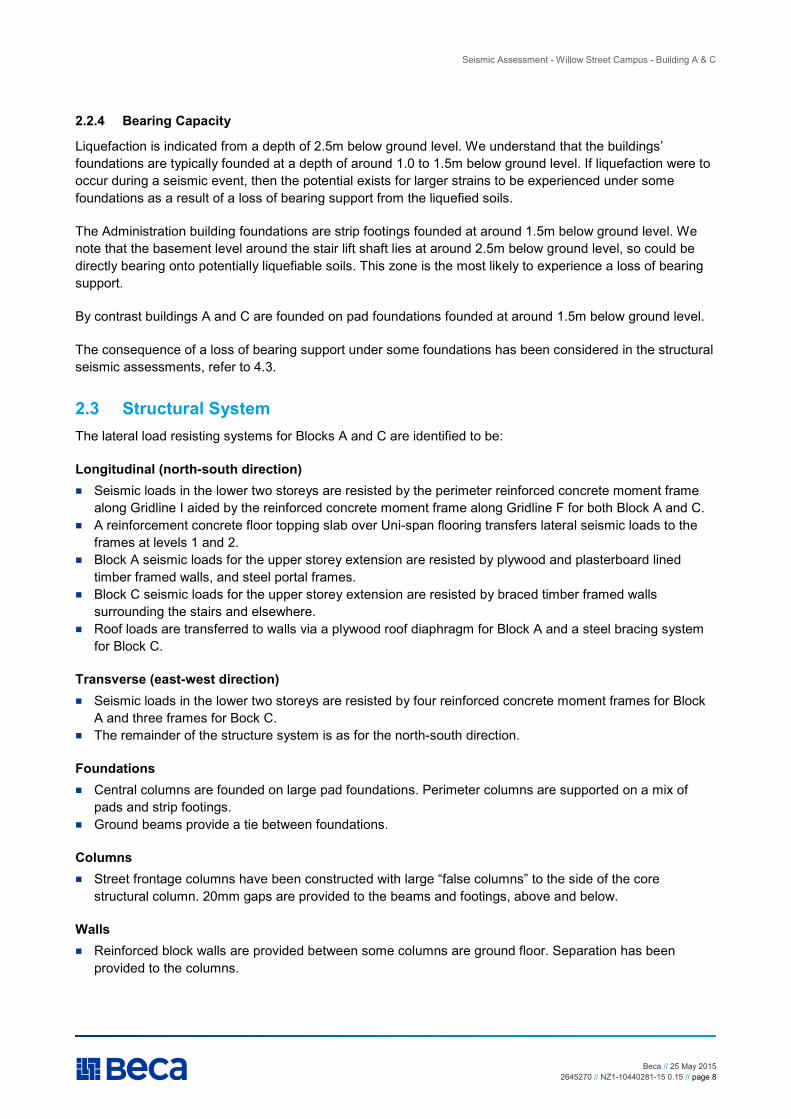
2.3 Structural System
The lateral load resisting systems for Blocks A and C are identified to be:
Longitudinal (north-south direction)
� Seismic loads in the lower two storeys are resisted by the perimeter reinforced concrete moment frame along Gridline I aided by the reinforced concrete moment frame along Gridline F for both Block A and C.
� A reinforcement concrete floor topping slab over Uni-span flooring transfers lateral seismic loads to the frames at levels 1 and 2.
� Block A seismic loads for the upper storey extension are resisted by plywood and plasterboard lined timber framed walls, and steel portal frames.
� Block C seismic loads for the upper storey extension are resisted by braced timber framed walls surrounding the stairs and elsewhere.
� Roof loads are transferred to walls via a plywood roof diaphragm for Block A and a steel bracing system for Block C.
Transverse (east-west direction)
� Seismic loads in the lower two storeys are resisted by four reinforced concrete moment frames for Block A and three frames for Bock C.
� The remainder of the structure system is as for the north-south direction.
Foundations
� Central columns are founded on large pad foundations. Perimeter columns are supported on a mix of pads and strip footings.
� Ground beams provide a tie between foundations.
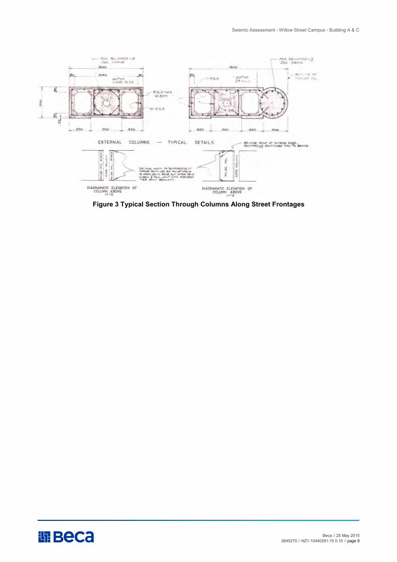
Columns
� Street frontage columns have been constructed with large “false columns” to the side of the core structural column. 20mm gaps are provided to the beams and footings, above and below.
Walls
� Reinforced block walls are provided between some columns are ground floor. Separation has been provided to the columns.
Seismic Assessment - Willow Street Campus - Building A & C
Beca // 25 May 2015 2645270 // NZ1-10440281-15 0.15 // page 9
Figure 3 Typical Section Through Columns Along Street Frontages
Seismic Assessment - Willow Street Campus - Building A & C
Beca // 25 May 2015 2645270 // NZ1-10440281-15 0.15 // page 10
3 Results of Seismic Assessment
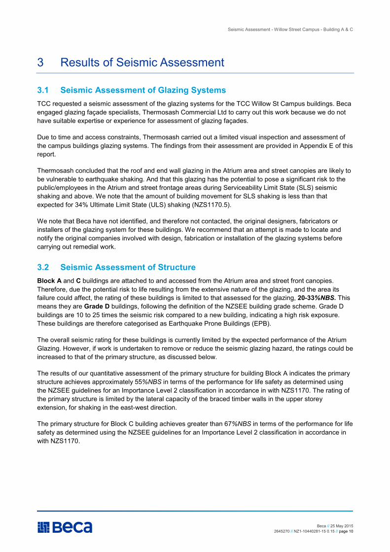
3.1 Seismic Assessment of Glazing Systems
TCC requested a seismic assessment of the glazing systems for the TCC Willow St Campus buildings. Beca engaged glazing façade specialists, Thermosash Commercial Ltd to carry out this work because we do not have suitable expertise or experience for assessment of glazing façades.
Due to time and access constraints, Thermosash carried out a limited visual inspection and assessment of the campus buildings glazing systems. The findings from their assessment are provided in Appendix E of this report.
Thermosash concluded that the roof and end wall glazing in the Atrium area and street canopies are likely to be vulnerable to earthquake shaking. And that this glazing has the potential to pose a significant risk to the public/employees in the Atrium and street frontage areas during Serviceability Limit State (SLS) seismic shaking and above. We note that the amount of building movement for SLS shaking is less than that expected for 34% Ultimate Limit State (ULS) shaking (NZS1170.5).
We note that Beca have not identified, and therefore not contacted, the original designers, fabricators or installers of the glazing system for these buildings. We recommend that an attempt is made to locate and notify the original companies involved with design, fabrication or installation of the glazing systems before carrying out remedial work.
3.2 Seismic Assessment of Structure
Block A and C buildings are attached to and accessed from the Atrium area and street front canopies. Therefore, due the potential risk to life resulting from the extensive nature of the glazing, and the area its failure could affect, the rating of these buildings is limited to that assessed for the glazing, 20-33%NBS. This means they are Grade D buildings, following the definition of the NZSEE building grade scheme. Grade D buildings are 10 to 25 times the seismic risk compared to a new building, indicating a high risk exposure. These buildings are therefore categorised as Earthquake Prone Buildings (EPB).
The overall seismic rating for these buildings is currently limited by the expected performance of the Atrium Glazing. However, if work is undertaken to remove or reduce the seismic glazing hazard, the ratings could be increased to that of the primary structure, as discussed below.
The results of our quantitative assessment of the primary structure for building Block A indicates the primary structure achieves approximately 55%NBS in terms of the performance for life safety as determined using the NZSEE guidelines for an Importance Level 2 classification in accordance in with NZS1170. The rating of the primary structure is limited by the lateral capacity of the braced timber walls in the upper storey extension, for shaking in the east-west direction.
The primary structure for Block C building achieves greater than 67%NBS in terms of the performance for life safety as determined using the NZSEE guidelines for an Importance Level 2 classification in accordance in with NZS1170.

Seismic Assessment - Willow Street Campus - Building A & C
Beca // 25 May 2015 2645270 // NZ1-10440281-15 0.15 // page 11
Table 1 presents the evaluated seismic performance in terms of %NBS of the individual structural systems in each loading direction.
Table 1 - Summary of Seismic Performance
System Direction Seismic Performance in
%NBS
Notes
Block A & C: Reinforced concrete frames
Both >67%NBS Beam and column hinging.
Block A & C: Cast-in-situ floor diaphragm
Both >67%NBS
Block A & C: Foundations Both >67%NBS
Assessed effect of loss of bearing support under one footing (one internal column and one corner column)
Block A: Braced timber-framed walls
Transverse (east-west) ~55%NBS
Plywood & plasterboard linings
Longitudinal (north-south) >67%NBS
Block C: Braced timber-framed walls
Both >67%NBS
Stairs Both >67%NBS
Link bridges Both >67%NBS
Assuming adjacent building movement is similar to Block A, and all ends constructed as per available details.
Atrium glazing roof and end walls Both 20-33%NBS
Street canopy glazing between buildings Both 20-33%NBS
More vulnerable than glazing elsewhere due to relative movement between adjacent buildings.
Street canopy glazing - other than between buildings
Both >34%NBS
<67%NBS

Seismic Assessment - Willow Street Campus - Building A & C
Beca // 25 May 2015 2645270 // NZ1-10440281-15 0.15 // page 12
4 Commentary on Associated Seismic Risks
4.1 Stairs
The Department of Building and Housing issued Practice Advisory 13 in response to concerns about stair collapse and damage observed in the Christchurch earthquake. The primary concern of this Practice Advisory is staircases with sliding support details in mid to high-rise multi-storey buildings.
We have assessed the expected performance of the stairs considering estimated building movements as defined by MBIE Practice Advisory 13. We believe the stairs are likely to remain available for egress for building drifts up to the level required by the advisory.
Figure 4 Section Through Stairs
4.2 Link Bridges
We have assessed the expected performance of the link bridges based on the available details and considering estimated building movements. We believe these can perform satisfactorily for the drifts we have calculated when the buildings area subject to 67% loading defined for the ULS in NZS1170.5.
Figure 5 Link Bridge End Support Detail

Seismic Assessment - Willow Street Campus - Building A & C
Beca // 25 May 2015 2645270 // NZ1-10440281-15 0.15 // page 13
4.3 Liquefaction
If liquefaction were to occur during a seismic event, the potential exists for a loss of bearing support to some pad foundations of the Block A and C buildings. This has been considered in our structural assessment of the buildings.
Our assessment shows that although there could be significant damage to the building if liquefaction were to occur and result in loss of structural support. The building is capable of maintaining structural integrity sufficient to achieve life safety objectives, as defined by the NZSEE guidelines.
4.4 Risks from Non-structural Building Elements
From our experience in evaluating similar buildings in Christchurch, non-structural building elements (façade glass, ceilings, internal walls, overhead services) constitute a significant hazard to building occupants, and proportion of the repair / reinstatement cost following an earthquake. In a moderate seismic event, some damage to non-structural elements would be expected.
For a new building, full-height partitions (glazed or Gib-board lining), glazed street facades and ceilings are normally designed to accommodate the building’s deformations.

Seismic Assessment - Willow Street Campus - Building A & C
Beca // 25 May 2015 2645270 // NZ1-10440281-15 0.15 // page 14
5 Assessment of Seismic Risk
5.1 Seismic Risk and Performance Levels
The overall building seismic score is limited by the findings of the glazing assessment which indicates that the Block A and C are Grade D buildings, following the definition of the NZSEE building grading scheme. Grade D buildings have approximately 10-25 times the seismic risk compared to a new building, indicating a high risk exposure.
If work is undertaken to increase the seismic rating of the glazing above that of the primary structure, then the overall seismic risk would be reduced. Block A (primary structure approx. 55%NBS) would be revised to a Grade C building. Grade C buildings have approximately 5-10 times the seismic risk compared to a new building, indicating a medium risk exposure. Block C (primary structure >67%NBS) would be revised to a Grade B building. Grade B buildings have approximately 2-5 times the seismic risk compared to a new building, indicating a low or medium risk exposure.
The New Building Standard requires a building to have a low probability of collapse in a 1 in 500-year “design level” earthquake (ie. an earthquake with a probability of exceedance of approximately 10% over the assumed 50 year design life of a building).
Relative Earthquake Risk
Building Grade Percentage of New Building Strength (%NBS)
Approx. Risk Relative to a New Building
Risk Description
A+ >100 <1 low risk A 80 to 100 1 to 2 times low risk B 67 to 80 2 to 5 times low or medium risk C 33 to 67 5 to 10 times medium risk D 20 to 33 10 to 25 times high risk E <20 more than 25 times very high risk A building achieving less than 34%NBS is categorised as an Earthquake Prone Building (EPB) and a building achieving less than 67%NBS is categorised as an Earthquake Risk Building (ERB). Block A and C
buildings are therefore categorised as an Earthquake Prone Buildings, limited by the Atrium and street canopy glazing.

Seismic Assessment - Willow Street Campus - Building A & C
Beca // 25 May 2015 2645270 // NZ1-10440281-15 0.15 // page 1
6 Seismic Retrofit and Strengthening
6.1 Retrofit and Strengthening Options
6.1.1 Structural Strengthening
The following seismic retrofit concept is to address the identified structural weakness in the lateral capacity of the timber wall bracing for upper storey extension to Block A. This concept has been developed for discussion with TCC.
We propose replacement of the wall linings for five walls on the second floor of Block A. This would consist of the removal of existing plasterboard linings, installation of standard Gib system hold down fixings to studs and installation of plywood and plasterboard linings as required for the Gib BR7 system. This strengthening is expected to raise the seismic performance of Block A to above 67%NBS as required by TCC.
Figure 6 Proposed Wall Strengthening Block A Level 2
6.1.2 Remedial to Atrium and Street Canopy Glazing
We recommend that remedial work is carried out for the Atrium and street canopy glazing is to raise the seismic performance of Block A to above 67%NBS as required by TCC. This could be achieved by removal, replacement, or suitable protection to vulnerable glazing and glazing support components. The objective would be to accommodate greater ability to sustain the differential movements expected for the two buildings.
6.2 Preliminary Cost Estimate
Costs estimates of remedial conceptual designs are to be provided separately.

Seismic Assessment - Willow Street Campus - Building A & C
Beca // 25 May 2015 2645270 // NZ1-10440281-15 0.15 // page 2
7 Next Steps
We recommend that TCC consider carrying out the following next steps:
� Carry out strengthening of the timber walls at level 2 of Block A. � Carry out remedial work to the Atrium and street canopy glazing.
Note: we recommend that an attempt is made to locate and notify the original companies involved with design, fabrication or installation of the glazing systems before carrying out remedial work.
Our assessment suggests that addressing these two items would lift the seismic score for Block A and C buildings to above 67%NBS.

Seismic Assessment - Willow Street Campus - Building A & C
Beca // 25 May 2015 2645270 // NZ1-10440281-15 0.15 //
Appendix A
Sources of Information

Seismic Assessment - Willow Street Campus - Building A & C
Beca // 25 May 2015 2645270 // NZ1-10440281-15 0.15 //
Sources of Information The following information was used to undertake the seismic assessment:
� Opus International Consultants Limited (2014). Tauranga City Council Civic Campus Structural Review – Wharf Street and Willow Street – Tauranga CBD. Prepared for Tauranga City Council.
� Documents obtained from Tauranga City Council comprising a set of scanned original Structural drawings.
� External and internal visual inspections of the building carried out on 20/02/2015. � The following documents and references were available to undertake the seismic assessment: � New Zealand Standard NZS1170 “Structural Design Actions”. � New Zealand Standard NZS3101:2006 “Concrete Structures Standard”. � New Zealand Standard NZS3404:2009 “Steel Structures Standard”. � New Zealand Society for Earthquake Engineering (NZSEE) “Guidelines on Assessment and Improvement
of the Structural Performance of Buildings in Earthquake”. 2006 New Zealand.
Seismic Assessment - Willow Street Campus - Building A & C
Beca // 25 May 2015 2645270 // NZ1-10440281-15 0.15 //
Appendix B
Seismic Assessment Assumptions
Seismic Assessment - Willow Street Campus - Building A & C
Beca // 25 May 2015 2645270 // NZ1-10440281-15 0.15 //
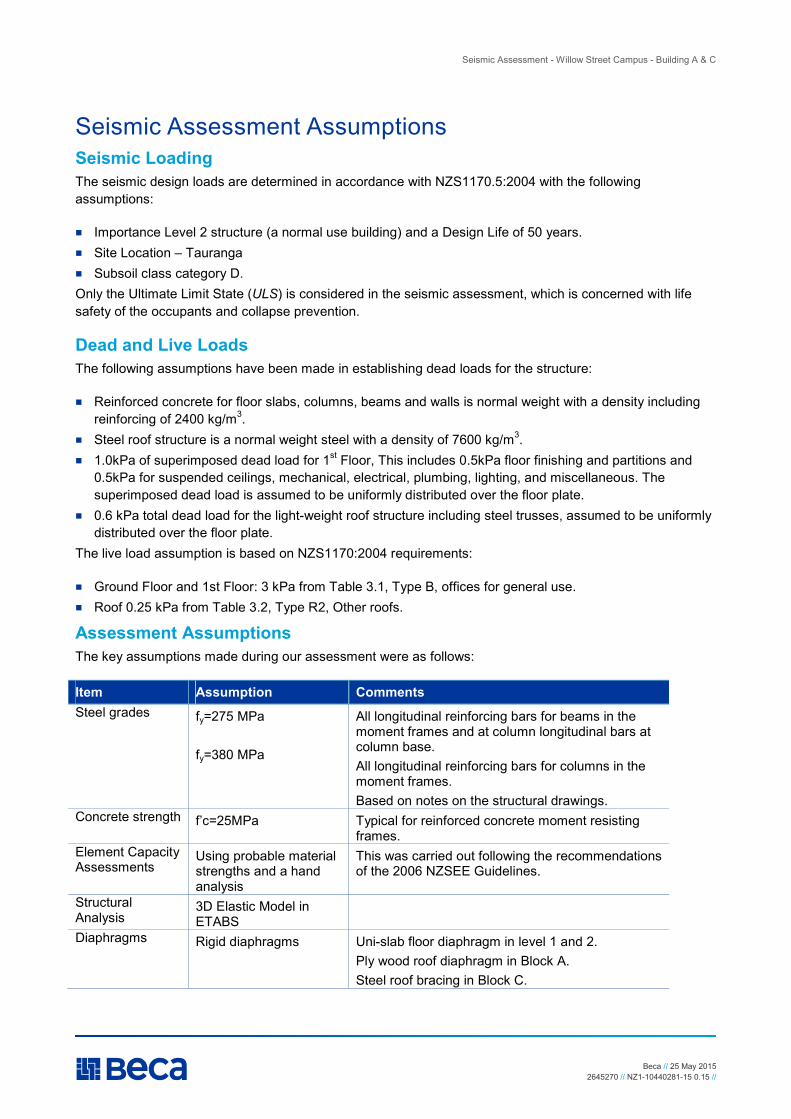
Seismic Assessment Assumptions Seismic Loading
The seismic design loads are determined in accordance with NZS1170.5:2004 with the following assumptions:
� Importance Level 2 structure (a normal use building) and a Design Life of 50 years. � Site Location – Tauranga � Subsoil class category D. Only the Ultimate Limit State (ULS) is considered in the seismic assessment, which is concerned with life safety of the occupants and collapse prevention.
Dead and Live Loads
The following assumptions have been made in establishing dead loads for the structure:
� Reinforced concrete for floor slabs, columns, beams and walls is normal weight with a density including reinforcing of 2400 kg/m3.
� Steel roof structure is a normal weight steel with a density of 7600 kg/m3. � 1.0kPa of superimposed dead load for 1st Floor, This includes 0.5kPa floor finishing and partitions and
0.5kPa for suspended ceilings, mechanical, electrical, plumbing, lighting, and miscellaneous. The superimposed dead load is assumed to be uniformly distributed over the floor plate.
� 0.6 kPa total dead load for the light-weight roof structure including steel trusses, assumed to be uniformly distributed over the floor plate.
The live load assumption is based on NZS1170:2004 requirements:
� Ground Floor and 1st Floor: 3 kPa from Table 3.1, Type B, offices for general use. � Roof 0.25 kPa from Table 3.2, Type R2, Other roofs.
Assessment Assumptions
The key assumptions made during our assessment were as follows:
Item Assumption Comments
Steel grades fy=275 MPa fy=380 MPa
All longitudinal reinforcing bars for beams in the moment frames and at column longitudinal bars at column base. All longitudinal reinforcing bars for columns in the moment frames. Based on notes on the structural drawings.
Concrete strength f’c=25MPa Typical for reinforced concrete moment resisting frames.
Element Capacity Assessments
Using probable material strengths and a hand analysis
This was carried out following the recommendations of the 2006 NZSEE Guidelines.
Structural Analysis
3D Elastic Model in ETABS
Diaphragms Rigid diaphragms Uni-slab floor diaphragm in level 1 and 2. Ply wood roof diaphragm in Block A. Steel roof bracing in Block C.

Seismic Assessment - Willow Street Campus - Building A & C
Beca // 25 May 2015 2645270 // NZ1-10440281-15 0.15 //
Item Assumption Comments
Accidental Eccentricity
Considered as part of ETABS analysis
Modelling ETABS and SpaceGass models included rigid offsets
The achievable seismic performance of the various structural elements can be estimated using the approach described in the 2006 NZSEE Guidelines. It assumes the Demand/Capacity ratio under the 100%NBS seismic forces (not factored by Sp/kµ) corresponds to the required ductility capacity (kµ). The ratio of the available and the required ductility capacity is the approximate achievable seismic performance (in terms of %NBS). A Structural Performance Factor Sp corresponding to the assumed ductility factor, kµ as per NZS1170.5 is assumed.
Seismic Mass
The seismic mass is computed adopting the NZS1170.5:2004 loading combination W = G + ΨE Qu = G +
0.3Qu. No area reduction factor is used to calculate the ultimate live load Qu, as a conservative assumption.
The additional floor seismic mass (excludes the self-weight of the members) is distributed equally to each node at the floor level in the computer model. The self-weight of the members is computed directly by the programme.

Seismic Assessment - Willow Street Campus - Building A & C
Beca // 25 May 2015 2645270 // NZ1-10440281-15 0.15 //
Appendix C
Building Inspection Photographs

Seismic Assessment - Willow Street Campus - Building A & C
Beca // 25 May 2015 2645270 // NZ1-10440281-15 0.15 //
Building Inspection Photographs
Figure 7 Examples of Columns with ‘fake column’ Sections
Figure 8 Typical Beam Column Junction Internal to Frame and on Corner

Seismic Assessment - Willow Street Campus - Building A & C
Beca // 25 May 2015 2645270 // NZ1-10440281-15 0.15 //
Figure 9 Low Level Walls Between Frames on South and West Elevations
Figure 10 Pedestrian Bridges between Blocks at 1st
and 2nd
Floor Levels
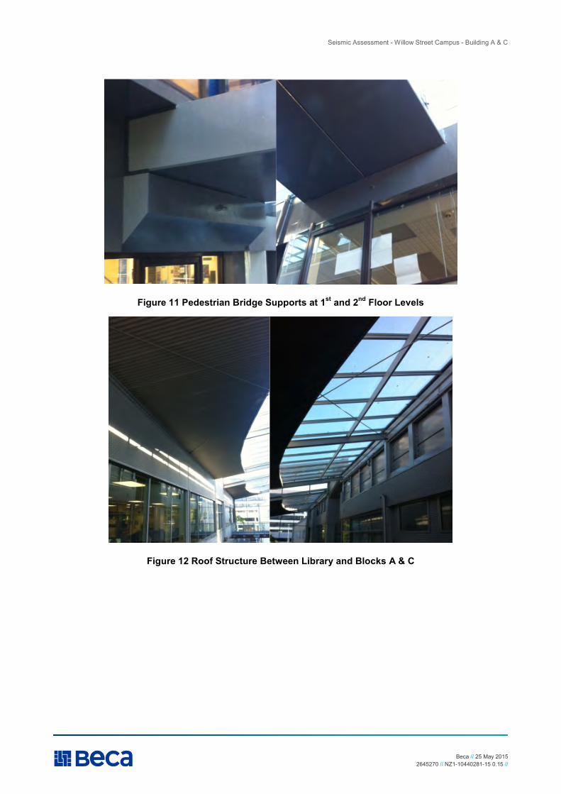
Seismic Assessment - Willow Street Campus - Building A & C
Beca // 25 May 2015 2645270 // NZ1-10440281-15 0.15 //
Figure 11 Pedestrian Bridge Supports at 1st
and 2nd
Floor Levels
Figure 12 Roof Structure Between Library and Blocks A & C

Seismic Assessment - Willow Street Campus - Building A & C
Beca // 25 May 2015 2645270 // NZ1-10440281-15 0.15 //
Appendix D
Structural Drawings

Seismic Assessment - Willow Street Campus - Building A & C
Beca // 25 May 2015 2645270 // NZ1-10440281-15 0.15 //
Appendix E
Glazing Assessment – Letter from Thermosash
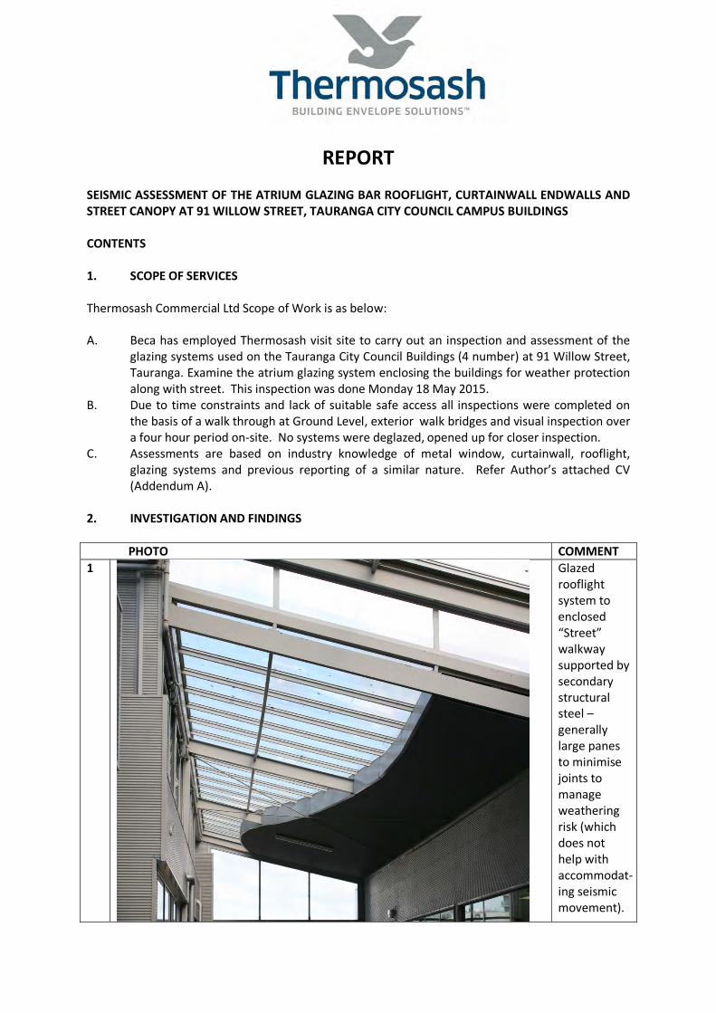
REPORT
SEISMIC ASSESSMENT OF THE ATRIUM GLAZING BAR ROOFLIGHT, CURTAINWALL ENDWALLS AND STREET CANOPY AT 91 WILLOW STREET, TAURANGA CITY COUNCIL CAMPUS BUILDINGS
CONTENTS
1. SCOPE OF SERVICES
Thermosash Commercial Ltd Scope of Work is as below:
A. Beca has employed Thermosash visit site to carry out an inspection and assessment of the glazing systems used on the Tauranga City Council Buildings (4 number) at 91 Willow Street, Tauranga. Examine the atrium glazing system enclosing the buildings for weather protection along with street. This inspection was done Monday 18 May 2015.
B. Due to time constraints and lack of suitable safe access all inspections were completed on the basis of a walk through at Ground Level, exterior walk bridges and visual inspection over a four hour period on-site. No systems were deglazed, opened up for closer inspection.
C. Assessments are based on industry knowledge of metal window, curtainwall, rooflight, glazing systems and previous reporting of a similar nature. Refer Author’s attached CV (Addendum A).
2. INVESTIGATION AND FINDINGS
PHOTO COMMENT
1 Glazed rooflight system to enclosed “Street” walkway supported by secondary structural steel – generally large panes to minimise joints to manage weathering risk (which does not help with accommodat-ing seismic movement).

Tauranga City Council Report 2 21 May 2015
2 Braced rooflight bay. We have had no ability to identify any structure/glazing system movement capacity- presume fixed at each end similar to the curtainwall endwall system support structural steel, connection design. NB. Refer Photo 9, 10 & 11
3 Head detail connected to structural steel mounted to the top of one building. With integrated head flashing.

Tauranga City Council Report 3 21 May 2015
4 Sill detail integrated glazing bar fixing shoe with overhang detail for weathering the junction.
5 Mid span glazing bar connection to secondary steelwork for structural support – these panes, (between directly adjacent buildings), have been glazed with one pane to manage weathering risk.
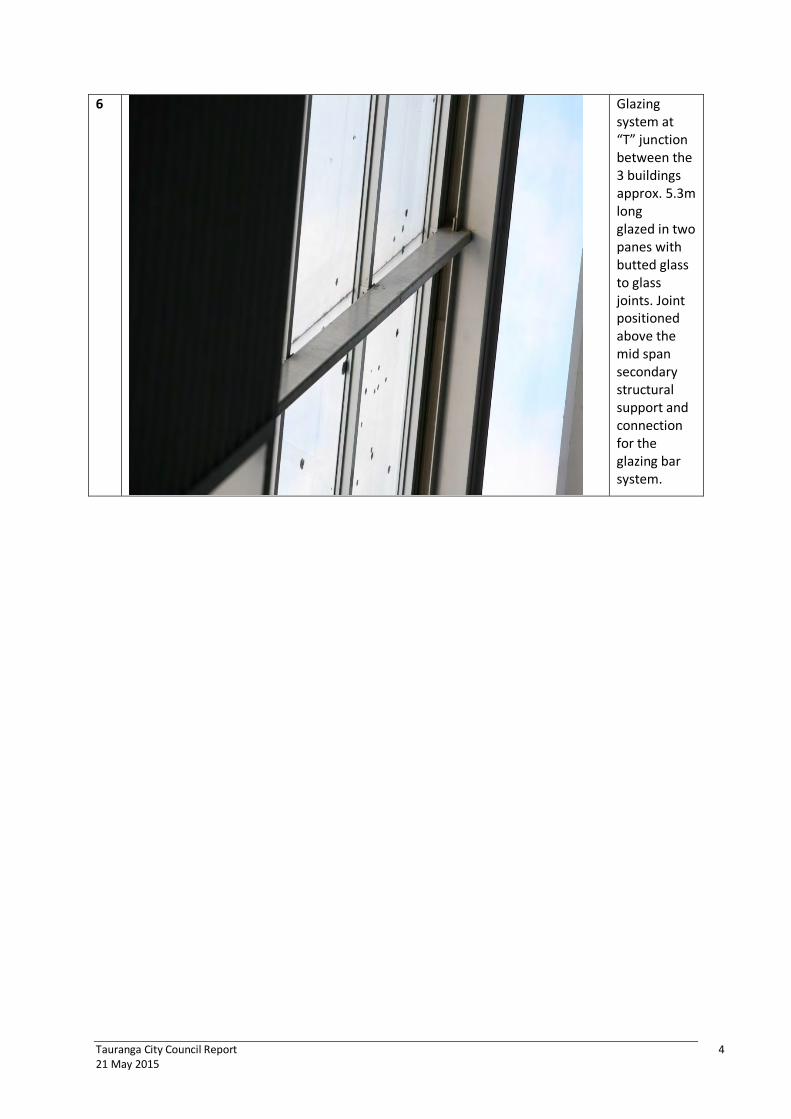
Tauranga City Council Report 4 21 May 2015
6 Glazing system at “T” junction between the 3 buildings approx. 5.3m long glazed in two panes with butted glass to glass joints. Joint positioned above the mid span secondary structural support and connection for the glazing bar system.
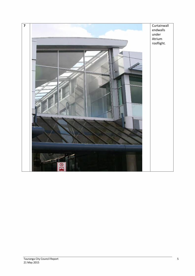
Tauranga City Council Report 5 21 May 2015
7 Curtainwall endwalls under Atrium rooflight.

Tauranga City Council Report 6 21 May 2015
8 Internal view of Main Entry bracing of leadlight will throw a lot of movement into the top row.
9 Hard fixed jamb condition of secondary steel support structure to curtainwall endwall.
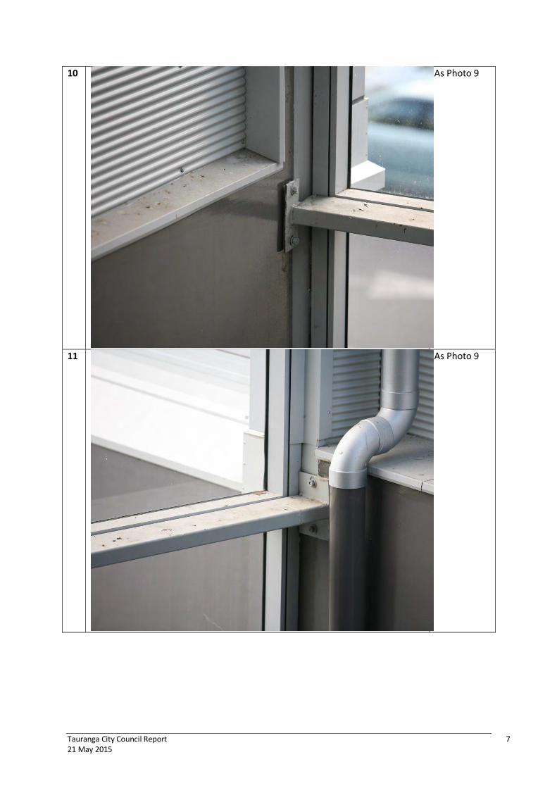
Tauranga City Council Report 7 21 May 2015
10 As Photo 9
11 As Photo 9
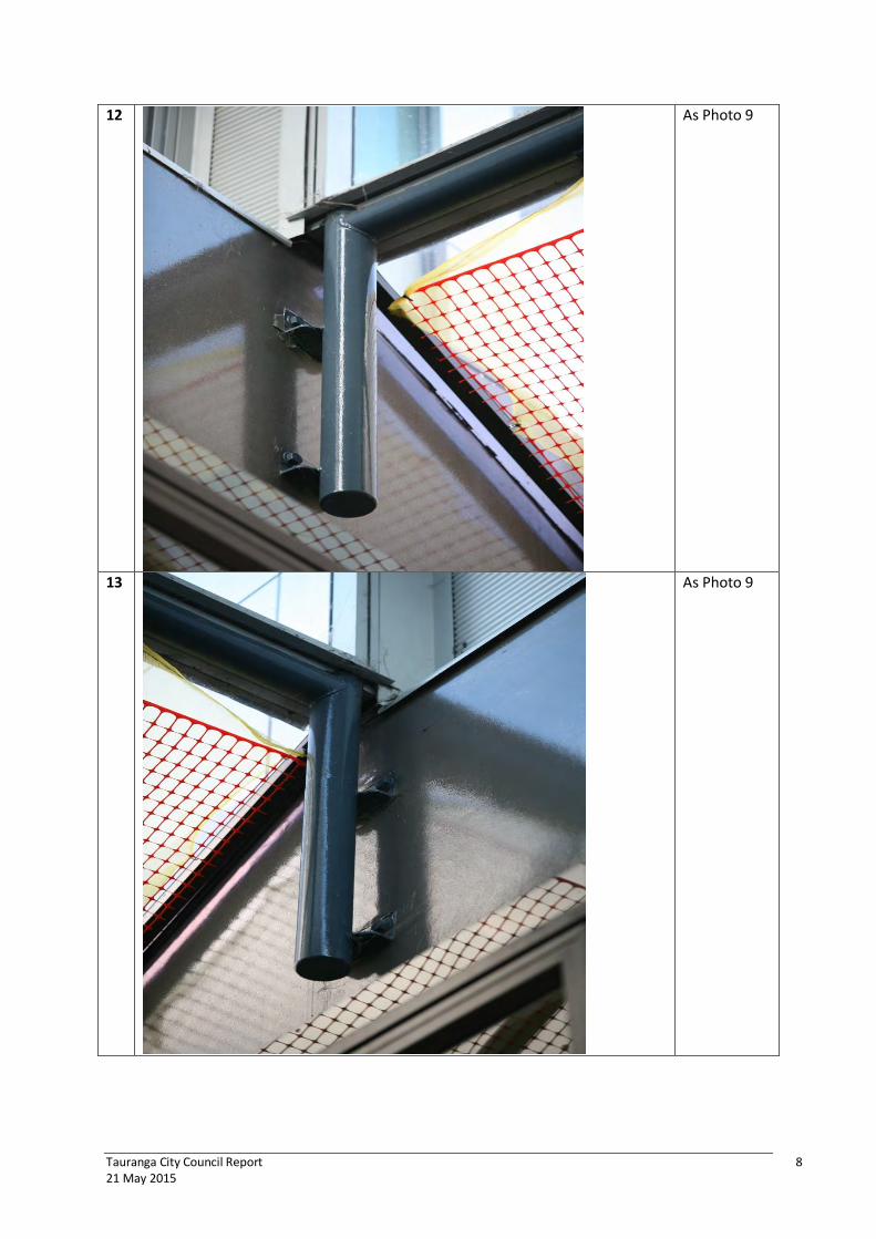
Tauranga City Council Report 8 21 May 2015
12 As Photo 9
13 As Photo 9

Tauranga City Council Report 9 21 May 2015
13A
As Photo 9

Tauranga City Council Report 10 21 May 2015
14 Curtainwall mullion connection to RHS structural steel support - one (12g?) fixing into RHS. No accommod-ation of thermal expansion contraction/ vertical structure movement?
15 Curtainwall sill condition. Deadload detail. NB. Mullions, a two part mullion is closed tight – no allowance for horizontal thermal expansion or accommodat-ion of any vertical structure movements.

Tauranga City Council Report 11 21 May 2015
16 Two part mullions to Wharf St Entrance curtainwall have been physically bolted to prevent them from bowing which they would have been doing before they were bolted together to prevent distortion due to vertical structure movement. Lack of provision for thermal expansion/ contraction.
17 As Photo 16

Tauranga City Council Report 12 21 May 2015
18 As Photo 16
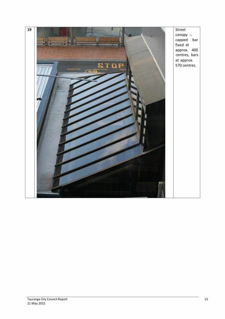
Tauranga City Council Report 13 21 May 2015
19 Street canopy – capped bar fixed at
approx. 400 centres, bars
at approx. 570 centres.
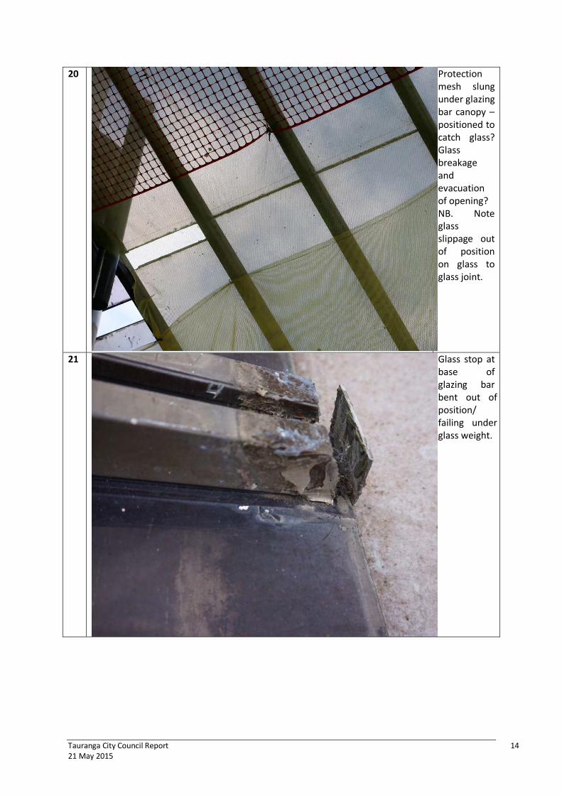
Tauranga City Council Report 14 21 May 2015
20 Protection mesh slung under glazing bar canopy – positioned to catch glass? Glass breakage and evacuation of opening? NB. Note glass slippage out of position on glass to glass joint.
21 Glass stop at base of glazing bar bent out of position/ failing under glass weight.
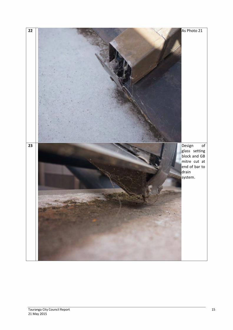
Tauranga City Council Report 15 21 May 2015
22 As Photo 21
23 Design of glass setting block and GB mitre cut at end of bar to drain system.

Tauranga City Council Report 16 21 May 2015
24 GB profile cap fixing
screw two piece profile 45mm sightline 75mm depth.
25 Identifies laminated Grade A safety glass has been used in canopy. Photo identifies edge delamination of laminated PVB ply 6.38mm thickness.

Tauranga City Council Report 17 21 May 2015
26 Identifies walkway bridge balustrade glass point fixed – monolithic toughened glass – risk of nickel sulphide stones causing spontaneous glass breakage in overhead application (refer Appendix F).
27 As Photo 26.

Tauranga City Council Report 18 21 May 2015
3. SUMMARY
Under NZS 1170 Structures Code (linked to NZS 4211, 4284, 4223) , the metal window, curtainwall, rooflight, glazing trade in a seismic event must design their system solutions to provide public safety up to the ULS building movements. Glass breakage/windows/curtainwalls/rooflights items must not fall onto areas below causing a safety hazard. The façade solution must remain serviceable up to the SLS building movement – above the SLS limit through to the ULS movement the building owner can expect maintenance and repair costs.
From the walk-through and observation only at Ground Level and from the walkway bridges with the help of a telephoto lens camera, we have identified that there are shortcomings in the design of the rooflights, canopies, glazed downstands/endwalls to the street Atrium glazing which pose a significant risk to the public/employees using this facility.
The Architect for this project carries primary design responsibility for façade design, its indicative detailing, specification and downstream supervision. The Architect’s tender package generally includes a specification transferring responsibility for the design, build, performance with downstream performance guarantees onto the successful tenderer. Generally procurement decision making is based on low price. The metal window, rooflight, curtainwall and glazing package has through the Architect’s specification a responsibility to comply with the Building Code and in this case NZS 1170 Structures Code, NZS 4211/NZS 4284 Window/Curtainwalling Performance Codes and NZS 4223 Glazing Code.
The Atrium rooflight system (and structural steel?) from observation has not been designed for seismic movement and in particular the differential movement between the various building structures. Both SLS and ULS differential movement will cause glass breakage and evacuation from the glazed roof system causing them to fall onto the public/employees evacuating the buildings via entrances below and onto the egress paths. We would highlight the industry’s minimum glass edge engagement and lack of anti-walk blocks (edge blocking ) allows the pane to move freely in the glazing pocket allowing the edge of engaged glass to disengage completely allowing the pane to fall from its opening.
NB. The upper rooflight system in the top up area at the “T” junction has two panes in its approximate 5.3m length butted which would not comply with industry (international) best practice highlighting the lack of design ability by the contractor who completed the work.
The safety glass type that has been used to glaze the rooflight could not be determined due to suitable access not being available in the time scale. The change to NZS 4223 requiring all glass above 5 m to be glazed in laminated glass did not come in practice until after 2007 when this building was built. Toughened glass breaks into small “dice” but has the potential to fall in clusters with a combined weight. Laminated glass would break with metal/glass contact and fall as one sheet each pane weighing roughly 73 kg (10.38mm laminated presumed) with indicatively 10-12mm edge engagement. (12 mm minimum glass edge cover required by the Code for overhead glazing does not include positional tolerance, installation tolerance, glass cutting tolerance.)
The vertical glazed end walls (curtainwall) is connected to secondary/primary structural steel RHS members spanning between the buildings. There is no movement capability in these structural connections supporting the curtainwall system to accommodate the differential building movement nominated - these will distort significantly under compression tearing the curtainwall brackets off the RHS/shearing the one 12g fixing (by observation) resulting in the curtainwall coming loose and

Tauranga City Council Report 19 21 May 2015
failing or the RHS fixings pulling out/failing in bending under differential building movement outwards (increasing opening width). (Beca to determine capacity of steel RHS member connections/brackets). With a single pane spanning floor to floor with 10mm engagement in a glazing pocket of 23 mm glass/metal contact initiating breakage will occur at ± 26mm seismic movement. All entrances have combined building differential SLS movements 30mm and above ULS movement 80/90mm. Annealed glass would most likely have been used in this application, this glass will break and evacuate the openings at these movements.
Street canopies – we note the glazing to these areas have all had under-slung overhead protection fitted. We were not advised why this had been installed - we presume that a pane of glass had fallen out? Our concern with the design of the canopy would be the structural connection to the steelwork/engineering of fixings used. The glass stops are all failing under deadload of the glass allowing the glass to slip out of position. There are no glass setting blocks at the glass stop allowing metal/glass contact which could easily cause glass breakage (not industry best practice). We are concerned about whether the glass has 12mm minimum glass engagement into the glazing pocket (mechanical entrapment), ie allowing for positional tolerance of glazing bar, squareness of glazing opening, glass cutting tolerance and positional tolerance of glass within the opening without anti-walk (edge) blocking to prevent movement under vibration/windload/seismic events to ensure minimum glass requirements are maintained. The canopy ULS (10mm) SLS (5mm) are low however the loss of minimum glass engagement highlights the risk of glass disengagement which is now being managed (has netting been engineered/tested?)
Our strong recommendation and advice, given the above comments, would be to replace the existing atrium rooflight, curtainwall endwalls and street canopy as soon as possible due to public safety and risk of glass falling from height into building egress paths, with a specific design solution which comply with the Beca Structural Engineer’s nominated movements. Any queries concerning the above please do not hesitate to contact the writer.
David Hayes BE (Mech), M.IPENZ, CPEng Façade Engineer Chief Executive Officer
APPENDICES A. DJ Hayes CV B. NZ Herald 5/10/2012 “Industry yet to nail down its flaws” C. Glass Digest June 15 1990 “Demystifying the Problems” D. Build Aug/Sept 2014 “Is Tendering Really the Way to Go?” E. ICBEST 2014 Technical paper “A Weatherproof Risk Matrix for Multi-storey Buildings” F. Nickel Sulphide Stones in Tempered Glass

DAVID HAYES
David Hayes is the CEO, Director/Owner of Thermosash Commercial Limited and subsidiaries Woods Glass (NZ) Ltd, (commercial glass and glazing company) and Window Engineering Consultants (façade testing facility).
Thermosash is New Zealand’s largest specific design commercial window, curtainwall, façade designer manufacturer and contractor. David has lead the Façade Engineering design/build contracting team providing façade solutions, inspections, remedial and performance testing, with more than 32 years ofexperience in this sector.
Auckland City Council Producer Statement Author No. 1403 Design / Design Review (PS1 / PS2) and Construction / Construction Review (PS3 / PS4) for façade value of $5M and above.
Thermosash Commercial Ltd
Director / Owner CEO Façade Engineer
Qualifications and Memberships:
B Eng – Bachelor of Engineering (Mechanical) (University of Auckland 1983) CPEng, MIPENZ Reg # 63019. Member Building Industry Authority, Building Envelope Advisory Pane,l 2004 – 2006. Member BRANZ Building Physics / Weathertightness Advisory Committee, 1993 - 1994. Member – NZIOB.
Specialisation:
Curtainwall Engineering of new & existing façades
Seismic Testing
David specializes in the design, testing, manufacture, QA and installation of all types of new facades including rainscreen cladding, curtainwalls, windows, doors, skylites, structural glass, balustrades, solarshading and feature façade elements. Thermosash operates the largest façade testing facility in New Zealand to AS/NZS 4284 and can complete in-situ testing for QA/QC checks to suit specific project requirements. David completes façade inspections of existing installations as required for weatherproofness structural adequacy and quality assessment.
KRTA Architectural Design for Earthquake, 1986 - 1987 BRANZ Seismic Testing for Wellington City Council, 1992
Years in Industry: 32 Key Project Experience:
1 May 1983 to present Thermosash Commercial Ltd – Façade Engineer
APPENDIX A
20

David Hayes 2015 21
Vistawall USA David trained in the USA with Vistawall Architectural Products (the second largest North American curtainwalling designer / manufacturer / contractor) over a five year period in the mid-1980’s. During this time Thermosash operated a Technology Agreement, where it purchased curtainwall system designs, engineering analysis packages and manufacturing / installation expertise from the Americans, which lay the foundation for its market-leading position. (Refer attached reference.)
Woods Glass started 1987 to present Woods Glass (NZ) Ltd – Director, Commercial Glass Glazing Contractor overview. Specific design glass solutions (refer attached profile.)
Window Engineering Consultants
1987 to present Design Build overview of Façade Test Laboratory testing and ongoing operation since.
Technology Agreement 1994 -Negotiated extension of Technology Agreement for supply of curtainwall design technical assistance with Wispeco (South Africa) – refer attached reference
Technology Agreement 1996 -Negotiated 7 year Technology Agreement with Al Karma, Delhi, India and subsequent extension for supply of curtainwall design assistance / technical support – traveled extensively to India over next 10 year period. – refer attached reference.
New Zealand Experience: 32 years - 2015
David’s experience as a façade, curtainwall and window designer has given him the unique experience of testing the performance of many specific design solutions to meet E2 requirements and witness their manufacture and installation on-site enabling him to assess buildability, durability and performance of the end product. David reviews structural calculations presented by Thermosash for façade structural compliance with B1 Structure requirements. David is a specialist in the weatherproofing design of pressure equalized and drained systems covering glass, aluminium, zinc, ACM, stainless, granite, terracotta, structural silicone, weatherseal sealant etc which has given him the experience to assess materials and systems for performance in accordance with B2 Durability requirements.
Projects: Major Project Specific Design Façade Solutions
University of Auckland, Science Building 302, commencing 2014 Integrated specific design total clad solution based on modular unitized curtainwall system – glass overglass, rainscreen zinc cladding, rainscreen composite aluminium, feature chevron fins (solarshades), seismic joints, mechanical louvres. Signed compliance with B1,B2 & E2 – 10 year Façade Performance Guarantee.
Exxon Mobil Permanent Facilities Compound, PNG commencing 2014 Modular unitized curtainwall with integrated solarshade feature, composite cladding and entrance doors - signed compliance with B1,B2 & E2 – 10 year Façade Performance Guarantee.
Wiri Prison Houseblocks, Auckland 2014 High security customized specific design Delta commercial window system. Signed compliance with B1,B2 & E2 – 10 year Façade Performance Guarantee.
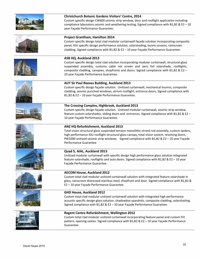
David Hayes 2015 22
Christchurch Botanic Gardens Visitors’ Centre, 2014 Custom specific design CW600 seismic strip window, door and rooflight application including compliance laboratory seismic and weathering testing. Signed compliance with B1,B2 & E2 – 10 year Façade Performance Guarantee.
Project Grantham, Hamilton 2014 Custom specific design total clad modular curtainwall façade solution incorporating composite panel, IGU specific design performance solution, solarshading, louvre screens, rainscreen
cladding. Signed compliance with B1,B2 & E2 – 10 year Façade Performance Guarantee.
ASB HQ, Auckland 2013 Custom specific design total clad solution incorporating modular curtainwall, structural glass suspended assembly, customs cable net screen and aero foil solarshade, rooflights, composite cladding, canopies, shopfronts and doors. Signed compliance with B1,B2 & E2 – 10 year Façade Performance Guarantee.
AUT Sir Paul Reeves Building, Auckland 2013 Custom specific design façade solution. Unitized curtainwall, mechanical louvres, composite cladding, seismic punched windows, atrium rooflight, entrance doors. Signed compliance with B1,B2 & E2 – 10 year Façade Performance Guarantee.
The Crossing Complex, Highbrook, Auckland 2013 Custom specific design façade solution. Unitized modular curtainwall, seismic strip window, feature custom solarshades, sliding doors and entrances. Signed compliance with B1,B2 & E2 – 10 year Façade Performance Guarantee.
ANZ HQ Refurbishment, Auckland 2013 Total vision structural glass suspended tension monolithic strand rod assembly, custom spiders, high performance IGU rooflight structural glass canopy, total vision system, revolving doors, PW1000 unitized seismic strip windows. Signed compliance with B1,B2 & E2 – 10 year Façade Performance Guarantee.
Quad 5, AIAL, Auckland 2013 Unitized modular curtainwall with specific design high performance glass solution integrated feature solarshade, rooflights and auto doors. Signed compliance with B1,B2 & E2 – 10 year Façade Performance Guarantee.
AECOM House, Auckland 2012 Custom total clad modular unitized curtainwall solution with integrated feature solarshade in glass, rainscreen distressed stainless steel, shopfront and door. Signed compliance with B1,B2 & E2 – 10 year Façade Performance Guarantee.
GHD House, Auckland 2012 Custom total clad modular unitized curtainwall solution with integrated high performance acoustic specific design glass solution, shadowbox spandrels, composite cladding, solarshading. Signed compliance with B1,B2 & E2 – 10 year Façade Performance Guarantee.
Regent Centre Refurbishment, Wellington 2012 Custom total clad modular unitized curtainwall incorporating feature panel and custom frit pattern, opening sashes. Signed compliance with B1,B2 & E2 – 10 year Façade Performance Guarantee.

David Hayes 2015 23
Telecom Tower, Wellington 2011 Custom total clad modular unitized curtainwall shaped in elevation incorporating integrated shadegrate and maintenance walkways. Signed compliance with B1,B2 & E2 – 10 year Façade Performance Guarantee.
Viaduct Events Centre, Auckland 2011 Custom total clad modular unitized curtainwall integrating curved heads, revolving doors. Signed compliance with B1,B2 & E2 – 10 year Façade Performance Guarantee.
Novotel, Auckland Airport, 2011 Custom total clad solution incorporating twin skin integrating unitized modular curtainwall with secondary Delta seismic strip windows – acoustic and fire separation and acoustic specific design glass solution, integral 11m span ground floor and revolving doors. Signed compliance with B1,B2 & E2 – 10 year Façade Performance Guarantee.
Asteron Centre, Wellington 2010 Custom specific design modular curtainwall incorporating specific design performance glass solution with integrated solarshade feature fins, balconies, balustrades and sliding doors. Signed compliance with B1,B2 & E2 – 10 year Façade Performance Guarantee.
Customhouse D4, Wellington 2010 Seismic unitized modular strip window solution incorporating performance specific design glass. Signed compliance with B1,B2 & E2 – 10 year Façade Performance Guarantee.
Commercial Building, Gordons, PNG 2010 Specific design façade incorporating unitized modular curtainwall integrated solarshading, shopfronts, doors and composite cladding. Signed compliance with B1,B2 & E2 – 10 year Façade Performance Guarantee.
NZI HQ, Auckland 2009 – 5 Star Green Star Building Total clad custom PW1000 feature curtainwall, CW600 custom inner skin of twin skin solution, parapet / soffit architectural panels, drop panels, PW 600 shopfront, Delta seismic, entrances - signed compliance with B1,B2 & E2 – 10 year Façade Performance Guarantee.
BNZ – Deloittes, Auckland 2009 – 5 Star Green Star Building Total clad solution PW 1000 curtainwall, stainless feature rainscreen cladding, tension truss structural glass at entry, shopfronts – signed compliance with B1,B2 & E2 – 10 year Façade Performance Guarantee.
21 Queen St, Auckland 2008 - 5 Star Green Star Building Total clad solution PW 1000 curtainwall solution, roof feature fin, total vision structural glass shopfronts, canopies, entrances – signed compliance with B1,B2 & E2 – 10 year Façade Performance Guarantee.

David Hayes 2015 24
Westpac Charterhouse, Auckland 2008 PW 1000 seismic punched windows, curtainwall mechanical louvres, shopfront, entrances, canopies, aluminium cladding – signed compliance with B1,B2 & E2 – 10 year Façade Performance Guarantee.
BNZ F1/F2, Wellington 2008 Total clad PW1000 curtainwall, feature 3D architectural panels, composite aluminium soffits, canopy entry doors – signed compliance with B1,B2 & E2 – 10 year Façade Performance Guarantee.
Stamford Plaza, Auckland 2007/08 Total clad façade solution PW1000 with integrated double hung sashes, Delta sliders, punched
windows, structural glass, completed façade testing to NZS 4284 - signed compliance with B1,B2 & E2 – 10 year Façade Performance Guarantee.
Sentinel, Takapuna 2007 Design build PW400 seismic strip window, Delta high performance weathering/acoustic sliding doors – signed compliance with B1,B2 & E2 – 10 year Façade Performance Guarantee.
Ironbank, Auckland 2007 Rainscreen Corten steel rainscreen cladding, custom solution fish scale structural glass clad lift shaft, PW 400 seismic strip windows – signed compliance with B1,B2 & E2 – 10 year Façade Performance Guarantee.
IRD, Christchurch 2007 Total clad solution PW1000 curtainwall, solarshading - signed compliance with B1,B2 & E2 – 10 year Façade Performance Guarantee.
Sovereign HQ, Takapuna 2007 Total Clad solution PW 1000 curtainwall, shadegrate mesh 100% solar shading screen integrated and supported by the curtainwall, composite aluminium cladding, rooflight – signed compliance with B1,B2 & E2 – 10 year Façade Performance Guarantee.
Wellington Regional Hospital 2006/7 Total clad design build custom PW 1000 curtainwall with integrated rainscreen aluminium planks– signed compliance with B1,B2 & E2 – 10 year Façade Performance Guarantee.
Wool House Refurbishment, Wellington 2005/07 Integrated total clad PW 1000 curtainwall solution integrating rainscreen zinc cladding, canopy rooflight– signed compliance with B1,B2 & E2 – 10 year Façade Performance Guarantee.
Kumutoto – Meridian – Site 7, Wellington 2006 – 5 Star Green Star Building Total clad solution, integrated twin skin PW 1000 mechanized timber & aluminium solar shading, glass rainscreen cladding, Delta curtainwall – signed compliance with B1,B2 & E2 – 10 year Façade Performance Guarantee.
Holiday Inn, Wellington 2006 Design build Delta curtainwall, PW 400 curtainwall, Delta sliders, solarshade screens – signed
compliance with B1,B2 & E2 – 10 year Façade Performance Guarantee.

David Hayes 2015 25
Auckland Museum, 2005/06 Custom structural glazed feature 3D warped dome skylight, glass floors, structural glass entrances, canopies - signed compliance with B1,B2 & E2 – 10 year Façade Performance Guarantee.
Maritime Tower, Wellington 2005 Total clad PW 1000 curtainwall solution incorporating solarshading, composite aluminium, structural glass canopy, internal spandrel walls – signed compliance with B1,B2 & E2 – 10 year Façade Performance Guarantee.
Ex Telecom HQ, Mayoral Drive, Auckland 2005 Total clad solution CW600 stick curtainwall - signed compliance with B1,B2 & E2 – 10 year Façade Performance Guarantee.
Waitakere Civic Building, Auckland 2005 Design build curtainwall solution - PW 400, PW 600, CW 600 curtainwalls, Delta windows - signed compliance with B1,B2 & E2 – 10 year Façade Performance Guarantee.
No. 3 The Terrace, Wellington 2005 Design build curtainwall solution - CW 600, PW 100 curtainwalls, skylite, – signed compliance with B1,B2 & E2 – 10 year Façade Performance Guarantee.
Unilodge, Christchurch 2005 Total clad design build PW 1000 composite cladding – signed compliance with B1,B2 & E2 – 10 year Façade Performance Guarantee.
AUT Business School, Auckland 2004/05 Total clad solution, PW1000 curtainwall, PW 600 unitized curtainwall, entrances - signed compliance with B1,B2 & E2 – 10 year Façade Performance Guarantee.
Residences, Auckland 2004/05 Delta high performance weathered/ acoustic sliders, mechanical louvres - signed compliance with B1,B2 & E2 – 10 year Façade Performance Guarantee.
University of Auckland Business School 2004 Design build total clad solution – PW 1000 custom curtainwall with stainless feature spandrel , tension truss, structural glass, feature rooflight, structural glass solarshading – signed compliance with B1,B2 & E2 – 10 year Façade Performance Guarantee.
SkyCity Grand Hotel, Auckland 2004 Design build total clad solution – PW 1000 custom unitized curtainwall incorporating integrated feature terracotta tiles, façade laboratory compliance test to specification AS/NZS 4284 – signed compliance with B1,B2 & E2 – 10 year Façade Performance Guarantee.
University of Auckland – Population Health 2003/4 PW 1000 curtainwall, windows, doors, cladding – design build solution PW 1000, Delta Window, solarshading – signed compliance with B1,B2 & E2 – 10 year Façade Performance Guarantee.
David Hayes 2015 26
142 Featherstone St Refurbishment, Wellington 2003 Total clad solution PW100 seismic strip windows, shopfronts, entrance doors, custom reclad access solution – signed compliance with B1,B2 & E2 – 10 year Façade Performance Guarantee.
Britomart Glass House, Auckland 2003 Custom structural glass louvre system, total clad solution, entrance, rooflights - signed compliance with B1,B2 & E2 – 10 year Façade Performance Guarantee.
Northern Roller Mills, Auckland 2002/3 35 storey tower curtainwall, full façade – design build total clad solution façade laboratory compliance test to specification AS/NZS 4284 – PW 1000 curtainwall, roof skylite, podium structural glass, revolving doors, rooflights, canopies . Signed compliance with B1,B2 & E2 – 10 year Façade Performance Guarantee.
Acute Services Building, Auckland Hospital 2002/3 Design build total clad solution PW 600, CW 40 auto doors, composite cladding – signed compliance with B1,B2 & E2 – 10 year Façade Performance Guarantee.
Lambton Tower, Wellington 2002 Total clad solution PW 1000 curtainwall, carpark screens, 50% free air – signed compliance with B1,B2 & E2 – 10 year Façade Performance Guarantee.
PWC Tower, Auckland 2001/2 Curtainwall, shopfronts and skylights – design build total clad solution, façade laboratory compliance test to specification AS/NZS 4284 – PW 1000 curtainwall rainscreen composite cladding, large span shopfront podium cladding canopies, signed compliance with B1,B2 & E2 - 10 year Façade Performance Guarantee.
Vodafone. Takapuna 2001 Total clad solution custom CW600, integrated solarshading, structural glass entrances - signed compliance with B1,B2 & E2 – 10 year Façade Performance Guarantee.
National Mutual Façade Refurbishment, Auckland 1998/99 Total clad, design build PW 100 custom curtainwall refurbishment, custom reclad access system solution – signed compliance with B1,B2 & E2 – 10 year Façade Performance Guarantee.
Te Papa Tongarewa Museum, Wellington 1993 Design build solution of the curtainwall, windows, solarshading, rooflight, entrance systems and internal display case structural glass elements. 5 laboratory weathering / seismic tests and 5 on-site QA/QC in-situ tests to substantiate system performance compliance with specific design façade specification. 10 year Façade Performance Guarantee.
National Bank Twin Towers, Auckland 1992 – Retrospective 5 Star Green Star Building
Total clad solution CW 400 stick curtainwall - signed compliance with B1,B2 & E2 – 10 year Façade Performance Guarantee.
David Hayes 2015 27
Park Royal Hotel (now Crown Plaza), Christchurch 1986/88 Total clad rooflight, double glazed, roof maintenance access ladder solution - signed compliance with B1,B2 & E2 – 10 year Façade Performance Guarantee.
Export Projects – Façade Technology Transfer Technical Support / Engineering / QA/QC Checklists / Manufacture & Installation
Thailand
Glashaus Chamnam Business Centre
Suvit Plaza Suvit Tower Times Square
India
Apollo Capital Court
Mahatta
Apollo
Dabur
South Africa
Auto & General Mutual 99 Capet UBS Blackheath

APPENDIX B
28

APPENDIX C
29
30

76 — Build 143 — August/September 2014
Departments/Research
By Dr Mark Hinton, former PhD student, School of Business and Management, University of Canterbury
COMPETITIVE TENDERING is entrenched in New Zealanders’ psyche as the way to procure construction, but who is best served by this approach? Research over the last 4 years suggests that the answer could be no one.
The PhD research through the University of Canterbury sought opinions about the competitive tendering process from those actively involved in the construction industry, including main contractors, subcontractors, consultants, architects and clients.
Why clients like tenders
The findings show that clients choose competitive tendering as they believe it will identify and secure the optimum price for their build.
However, focusing on cost can attract unintended consequences, not only detracting from the quality of the finished product but also increasing the final build price. For those carrying out the construc-tion, the margins achieved on completion also often fall short of those anticipated at the tendering stage.
When competition causes inefficiencies
A look at the actions of those involved at the pre- and post-tender stage in the procurement process explains the link between competi-tion and inefficiency.
Traditionally, the average commercial project may see between three and five main contractors asked to submit a bid. Main contrac-tors then request pricing from their own subcontractors. Historical relationships between main contractors and subcontractors often mean they have those they would prefer to work with.
Lack of trust plays out
In other instances, there can be a lack of trust between parties. This lack of trust that, balanced against a desire to work alongside preferred contractors, drives what can be seen as undesirable tender practices.
Subcontractors were found to protect themselves by holding on to a prepared tender for as long as possible, submitting to the
Is tendering really the way to go?
Competitive tendering is a common practice, but research suggests that it may not only hinder efficiency, it may also encourage some
questionable actions.
APPENDIX D
31
Build 143 — August/September 2014 — 77
main contractor just prior to the close of tenders. Even then, many submissions are invariably strewn with tags.
From the perspective of some subcontractors, this minimises the time available for a main contractor to shop around or reveal their price to a favourite subcontractor, who may subsequently undercut them.
It also limits the time a main contractor has to thoroughly evaluate the compliance of a tender, especially one of a more technical nature.
Some reading this may refute that practices such as price shopping exist in New Zealand, confident that assurances of confidentiality are robust. Regrettably, however, others found this to be a familiar sequence of events.
Tags may foster pricing advantage
Tags can be included within tender submissions for legitimate reasons, such as when a discrepancy may exist between a drawing and specifications. They may also occur as the result of a strategic business decision to disguise an artificially low tender and foster an early pricing advantage.
For example, a subcontractor will offer pre-arranged discounts on their bids to preferred main contractors as a way of improving the possibility of both parties securing a contract. This type of arrangement is ordinarily intentionally discreet.
Worries about payment
There can be several reasons why a subcontractor would offer selective pricing advantages. The most obvious is that some main contractors are poor or late payers, so a subcontractor will be prepared to give away some margin on the basis that aiding a particular main contractor will improve their own cash flow. Main contractors that do not withhold retention payments from subcontrac-tors commonly go to the head of the preferential main contractors list.
The notion of price discrimination also persists because many main contractors and subcontractors appreciate the tangible benefits of the efficiencies that can be achieved from ongoing working relationships. Subcontractors, in particular, are aware that good project manage-ment drives efficiencies across a project.
A degree of manoeuvring during the tendering process is understand-able as companies attempt to align with organisations that offer the greatest efficiencies, equating with a positive impact on the bottom line.
Post-tender manoeuvres
This drive to improve profitability showed up frequently during this research, especially during the post-tender negotiation stage,
once a contract has been awarded to a main contractor and prior to letting to subcontractors.
Although it is frequently a requirement that main contrac-tors include trade summaries, this does not always eventuate. Sometimes, it is an oversight, but at other times, summaries may be intentionally withheld, enabling the opportunity for further negotiation.
Post-tender negotiations between main contractors and subcon-tractors are understandable and acceptable in most instances. What upsets many subcontractors is when a main contractor who has won a contract partially on the basis of the subcontractor’s bid, then goes on to retrospectively financially squeeze the subcontractor by seeking discounts and reductions.
Subcontractors often work on meagre margins and may relent under pressure rather than lose a potential contract. The trickle-down effect is that the subcontractor then pressures their own supply chain or seeks to minimise their own costs by substituting materials with cheaper alternatives.
Advantages of negotiating
With the enormous demand for construction in Christchurch, we are witnessing a transition away from competitively tendered projects to more negotiated contracts.
However, negotiated contracts usually only extend to include the main contractor, and up to 95% of the value of most construction projects rests with subcontractors, who continue to be recruited by competitive tender.
This means we are inadvertently diminishing many of the advan-tages that negotiating may bring to procurement by ignoring where most of the costs and opportunities for savings and efficiencies are.
Competition model has flaws
There are other forms of procurement that the industry here and overseas is reluctant to widely adopt, continuing to remain committed to competition as a mechanism to achieve value.
Arguably, this is a flawed model, encouraging behaviours during both the pre- and post-tender stage that many in the construction industry consider to be unethical and that may inadvertently have ongoing repercussions impacting the quality of the built environment and the productivity and efficiency of the industry.
Note Mark Hinton was a BRANZ scholarship recipient. The opinions
expressed in this article are those of the author and do not necessarily reflect
those of BRANZ.
32

APPENDIX E
33

34
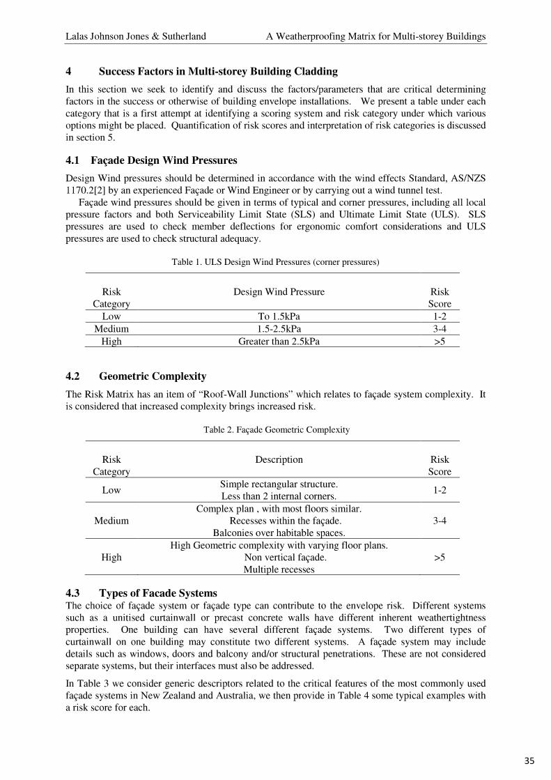
35

36

37

38

39

40

41

42

REPRINTED FROM THE GLASS INDUSTRY / DECEMBER 1978
Nickel Sulfide Stones In Tempered Glass An examination of the probability of spontaneous breakage due to these defects found in glass
By JOHN D. MACKENZIE University of California, Los Angeles, Cal.
The John Hancock Tower in Boston is a 60-story building and has 10,344 glass windows each measuring 4½ feet by 11½ feet. In January, 1973, during a severe storm, 16 windows were broken, and many more were damaged by the falling glass fragments. Subsequently, 2,400 windows were removed and the windows covered with plywood.1 ByAugust, 1975, all the original annealed glass had been replaced by one-half-inch-thick tempered glass. Because of the extensive damage in 1973 these 10,344 pieces of tempered glass have attracted a great deal of attention.
Tempered glass has been in use for a long time, of course. On rare occasions, it has been known to undergo spontaneous breakage. Usually, the exact cause of fracture would be unknown.
Because of the increasing usage of tempered glass and the notoriety of the John Hancock Tower, the spontaneous breakage of tempered glass has now become a topic of public concern. Such spontaneous breakages are attributed to defects in the glass and, according to many publications, the “most common” defects are nickel sulfide stones.2-4
Nickel sulfide stones, relatively unknown even to many experienced glass scientists and engineers, have practically become a household word. Further, with headlines such as “Small stones playing big part in Hancock breakage,” there is confusion between the original 1973 extensive glass breakage (which had nothing to do with tempered glass) and the role of nickel sulfide stones.5
What then are nickel sulfide stones? How common are they? Do they really cause widespread breakage of tempered glass? An attempt is made in this report to provide answers to these questions.
Nickel sulfide stones are uncommon defects in glass. In an extensive survey of stones in glass, Ono and Fukui made no mention of nickel sulfide.6 Similarly,other reference texts contain nothing on these defects.7, 8 In those rare
instances when nickel sulfide stones were found in flat glass, they generally existed in small polycrystalline spheres, 0.1 to 2mm in diameter and with a metallic appearance.9-12 These inclusions were found to be Ni3S2, Ni7S6 and Ni1-xS where x = 0 to 0.07. Frequently, these also contained Fe in solid solutions.11 The small stones aremade up of smaller grains of Ni1-xS, and their stoichiometry can vary within the stone. Apparently, only the Ni1-xS phase is responsible for spontaneous breakage of tempered glass.9 Stoichiometric NiSis known to undergo a phase transformation at 379oC.12
Transformation of the high temperature hexagonal a-NiS to the low temperature rhomgohedral ß-NiS is accompanied by a volumetric expansion of 2.38%. With increasing departure from stoichiometry, the transformation temperature decreases and reaches 280o for Ni0-94O. At the same time, the transformation also becomes increasingly sluggish with increasing x.13 For instance, with Ni0-94O, only some 40% of the a-NiS is transformed to the thermodynamically stable ß-NiS after 16 hours at 200oC.10 Because ofthis sluggishness at even high temperatures, highly non-stoichiometric NiS is unlikely to cause spontaneous breakage. The stoichiometric a-NiS and the a-Ni1-xS phases are all easily quenched from above 379oC topreserve their structures at room temperature.13 However, even thestoichiometric a-NiS would partially invert to the ß-phase after some months at room temperature.13
Annealed glass samples have been found to contain the a-NiS phase at room temperature.10 In some cases,the low temperature ß-NiS phase was found at the origins of fracture of glasses which have undergone spontaneous breakage.10 Thus, it hasbeen postulated that in the process of tempering, if a-NiS was present and if its chemical composition was close to
stoichiometry, its structure could be quenched in and would remain so for long periods of time at room temperature. Subsequently, if the glass was heated, in sunlight for instance, there could be a possibility that the a-ß transformation would occur rapidly. If these inclusions were located in that interior portion of the tempered glass which was in tension, the volumetric expansion could cause spontaneous breakage.14, 15
If this hypothesis is correct, one must then consider the probability of nickel sulfide stone-induced spontaneous breakage in tempered glass.
The first question is the probability of the presence of a particular nickel sulfide phase. Sulfur presumably comes from sodium sulfate. If no NiO is added to the batch as a colorant, then it is unlikely though not impossible that nickel sulfide can be formed. However, Ni could come from fuel oil used in the combustion, from refractories, or could originate from nickel-bearing alloys of the machinery used to treat the batch.10
Even if nickel ions and sulfate ions are present in the melt, it is not certain that any nickel sulfide will form. It is of course less certain that a-NiS will form instead of Ni3S2 and Ni7S6. The liquidus temperatures in the relevant part of the Ni-S phase diagram are less than 1000oC.13 Thus, the nickel sulfidephases formed would be in liquid droplets suspended in the molten glass. Calculations by Stokes’ law indicate that these spheres would fall at the rate of 1 to 10mm per minute.11 Depending ontheir positions in the glass tank and the flow pattern, some will fall to the bottom.
Any inclusion embedded in the solid glass, if its expansion coefficient is different from that of the glass, and if the glass is quenched, could cause internal stresses. The expansion coefficients of the nickel sulfides are unknown. Of the nickel sulfide crystallites which remained in the glass when it has solidified, Ni3S2, Ni7S6 and Ni1-xS of high nickel-deficiencies,
APPENDIX F
43

despite the possibility of expansion mismatch, are apparently harmless since only a-NiS was shown by laboratory experiments to cause spontaneous brakage.10 Thus, it mustbe concluded that the probability of the presence of particular NiS stones in glass which are “harmful” is very low.
If a-NiS inclusions are indeed formed in the glass, there is no certainty that when the glass is quenched during the tempering process, the a-ß transformation process does not also simultaneously occur. If it does, the glass will either break immediately or will now contain the harmless ß-NiS. On the other hand, if a-NiS is indeed preserved at room temperature, it will transform slowly to the ß-form over a period of months or years.13 The slowincrease of volume accompanying this transition need not cause internal fracture.
Assuming the volumetric expansion is 2.4%, the slowly increasing internal pressure experienced by the glass surrounding the NiS sphere is estimated to be 140,000 p.s.i. The tensile strengths in the interior of soda-lime glasses are of the order of 500,000 p.s.i.16 Thus, unless the shape of thea-NiS particles is so irregular that stress concentration results at some points along the inclusion-glass surface, the breakage of glass is improbable. The surface of tempered glass is in compression whereas the interior is in tension. If a-NiS stones are present in the glass, the probability of breakage when the a-ß transformation occurs will be greater if the stones are located in the central tensile region of the glass.
When the surface or edge of fully tempered glass is penetrated sufficiently through the compression layer, the residual tensile stresses are released and the entire glass immediately breaks into small fragments. This break pattern is known as “dicing.” Thus, if a a-NiS stone is trapped in the central tensile region of the interior of a fully tempered glass window, the instantaneous transition of the a-NiS to ß-NiS will probably cause spontaneous breakage of the entire window.
Tempered glass is some three to five times stronger than annealed glass. For reasons of safety and strength, tempered glass has obvious import-ance. However, though the probability is minimal spontaneous breakage due to a-NiS stones may still occur. This possibility can be further minimised by an additional heat treatment of the glass at the plant at about 200oC aftertempering to enhance a-ß transition. For instance, Merker10 had shown thatone hour at 200oC was ample tocompletely transform a-NiS to ß-NiS, while Schaal and Pieckert15
recommended a 240oC heat-soak forthree hours. Such treatment can often cause a slight reduction of the strength of tempered glass.17
This additional heat treatment does not guarantee that nickel sulfide stones
would be eliminated. A alternative would be the use of heat strengthened glass instead of fully tempered glass. Heat-strengthened glass is partially tempered glass having strengths approximately twice that of annealed glass.18, 19
The technical reasons for the use of heat-strengthened glass are as follows: The dangerous stones are those of relatively high purity.14 Such stones aredangerous because they convert not instantaneously, but rapidly at high temperatures and slowly at use temperatures, to the stable beta form. Most of these stones will convert spontaneously during the relatively slow cooling that is used for heat strengthening, and thereby become harmless; whereas they would remain in a “loaded” or unstable condition if quickly chilled by standard thermal full-tempering.
Conclusions Contrary to popular belief, it has
been shown above that nickel sulfide stones are actually rare defects in glass. If and when they are present, only the high temperature a-NiS is likely to cause spontaneous breakage in fully tempered glass.
There is little doubt that spon-taneous breakage of fully tempered glass has been reported periodically. This does not mean that nickel sulfide stones are always, indeed even frequently, the culprit. Heat-strength-ended glass offers twice the strength of annealed glass with practically no risk of spontaneous breakage. It is the obvious candidate to replace full tempered glass in many applications.
References (1) W.Martin, Architectural Record, June
117 (1977) (2) Newsweek, Oct. 10, 1977, page 180 (3) ENR, Sept 18, 1975, page 40 (4) New Times, Sept 16, 1977, page 23 (5) Boston Globe, Aug 14, 1977 (6) T. Ono and T. Fukui, Repts. Res. Lab.
Asahi Glass Co. Ltd, 22, 61 (1972) (7) The Handbook of Glass Manufacture,
Ed. By F. V. Tooley, Books for Industry, Inc., New York (1974)
(8) Terminology of Defects in Glass, International Commission on Glass, Chalerol, Belgium (1969)
(9) K. Wohllebon, H. Woelk and K. Konopicky, Glastech, Ber, 39. 329 (1966)
(10) L. Merker, Glastech, Ber, 47, 115, (1974)
(11) H. Tabuchi, Proc, 10th Int. Cong. on Glass, 3, 54, (1974)
(12) R. Wagner, Glastech, Ber, 30, 296 (1977)
(13) G. Kullerud and R. A. Yund. J. Petrology 3, 126 (1962)
(14) E.R Ballantyne, Commonwealth Scientific and Industrial Research Organization, Commonwealth of Australia, Rept No.08.15 Australia (1961)
(15) R. Schaal and W. Piekert, Schwe Alum, Rundich 22, 383 (1972)
(16) F. M. Ernsberger, Phys. Chem, on Glasses, 10, 240 (1969)
(17) J. J. Kerper and T. O. Scuderic, J.Am. Ceramic Soc. 49, 613 (1966)
(18) D. J. Segin, Glass Digest, Oct. 15, 60 (1977)
(19) Engineering Standards Manual, Glass Tempering Ass’n, December (1976)
About the Author
Dr. John D. Mackenzie is an internationally recognized expert in the science and technology of glasses and ceramics. He has published over 120 papers and edited six books in this general area. His numerous honors include the S.B.Mayer Award of the American Ceramic Society for the most outstanding papers in glass technology for the period 1963-64, the Lebeau Medal of the French Society for High Temperature Materials in 1969, and the Toledo Award of the Northwestern Ohio Section of the American Ceramic Society in 1973 for outstanding contributions and distinguished achievements in the glass and ceramic industries.
Dr Mackenzie has been awarded 11 U.S. patents on glass and ceramics. He has served as chairman of the Committee on the Electrical Properties of Glass for the International Glass Commission and was a U.S. representative on the Commission. He was elected to the U.S. National Academy of Engineering in 1976.
Prof. Mackenzie who is editor-in-chief of the “Journal of Non-Crystalline Solids,” received his Bachelor’s degree from Birkbeck College and his Ph.D degree from Imperial College, both located in London. He was a post-doctoral Research Fellow and Lecturer at Princeton University, after which he became the Imperial Chemical Industries Fellow at Cambridge University in England for one year. He then joined the General Electric Co. Research Laboratory in Schenectady, N.Y., as a research scientist and was later appointed professor of materials science at Rensselaer Polytechnic Institute. He became a professor of engineering and applied science at UCLA in 1969.
44
Seismic Assessment - Willow Street Campus - Building A & C
Beca // 25 May 2015 2645270 // NZ1-10440281-15 0.15 //
Appendix F
Estimated Building Seismic Displacement
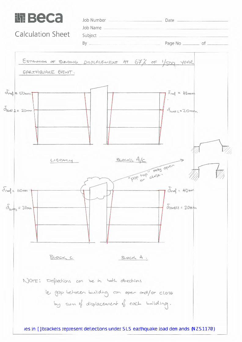
cwf
Text Box
2645270
cwf
Text Box
TCC Project Clean
cwf
Text Box
Glazing Assessment
cwf
Text Box
CWF
cwf
Text Box
06/05/2015
cwf
Text Box
1
cwf
Text Box
3
cwf
Text Box
(25mm)
cwf
Text Box
(20mm)
cwf
Text Box
(10mm)
cwf
Text Box
(10mm)
cwf
Text Box
(20mm)
cwf
Text Box
(10mm)
cwf
Text Box
(20mm)
cwf
Text Box
(10mm)
cwf
Text Box
Values in ( ) brackets represent deflections under 34% ULS earthquake load demands (NZS1170) Values in [ ] brackets represent deflections under SLS earthquake load demands (NZS1170)
cvl
Text Box
[20mm]
cvl
Text Box
[15mm]
cvl
Text Box
[8mm]
cvl
Text Box
[8mm]
cvl
Text Box
[15mm]
cvl
Text Box
[8mm]
cvl
Text Box
[15mm]
cvl
Text Box
[8mm]

cwf
Text Box
(15mm)
cwf
Text Box
(20mm)
cwf
Text Box
(20mm)
cwf
Text Box
(25mm)
cvl
Text Box
[10mm]
cvl
Text Box
[15mm]
cvl
Text Box
[15mm]
cvl
Text Box
[20mm]

cwf
Text Box
(15mm)
cwf
Text Box
(20mm)
cwf
Text Box
(20mm)
cwf
Text Box
(25mm)
cvl
Text Box
[10mm]
cvl
Text Box
[15mm]
cvl
Text Box
[15mm]
cvl
Text Box
[20mm]

Seismic Assessment - Willow Street Campus - Building A & C
Beca // 25 May 2015 2645270 // NZ1-10440281-15 0.15 //
End of Seismic Assessment – Willow Street Campus – Building A & C Report (20 March 2015)

Beca // 25 May 2015 2645270 // NZ1-10526613-12 0.12 // page 14
Appendix C
Plan of Opus Test Locations

104/2014 SCALE 1:NTS 29B302_00
APPENDIX A: TESTING LOCATION PLAN
Baycourt
Administra on
Building
TCC Library & Offices
CPT01 CPT02
CPT04 & Shear Wave Test
CPT03
CPT05
Key
‐ CPT test loca on (approximate loca on)
‐ Contours
cvl
Pen
cvl
Pen
cvl
Pen
cvl
Pen
cvl
Pen
cvl
Arrow

Beca // 25 May 2015 2645270 // NZ1-10526613-12 0.12 // page 15
– Building A & C Report (20 March 2015)
Appendix D
Results Summary Plan
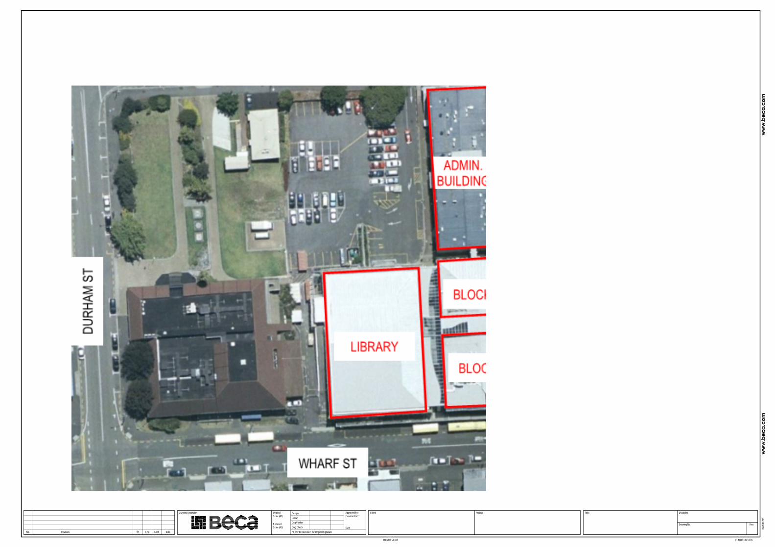
No. AppdRevision By Chk Date
Drawing Originator:
DO NOT SCALE
* Refer to Revision 1 for Original Signature
Scale (A1)
Scale (A3)Reduced
Dwg Check
Dsg Verifier
Drawn
Original DesignConstruction*
Date
Approved For Client: Project:
IF IN DOUBT ASK.
Title:
Drawing No.
Discipline
Docu
ment
No.
Rev.
Drawing Plotted: 26 Sep 2011 4:30 p.m.
DRAW
ING2
.DW
GBL
UEBE
AM
bf2
Group
STRUCTURAL
bf2
Text Box
2645270-SE-K000
bf2
Text Box
B
bf2
Text Box
PROJECT CLEAN
bf2
Text Box
RESULTS SUMMARY PLAN
bf2
Text Box
TAURANGA CITY COUNCIL
bf2
Text Box
bf2
Text Box
bf2
Text Box
bf2
Text Box
bf2
Text Box
bf2
Text Box
bf2
Text Box
bf2
Text Box
bf2
Text Box
bf2
Text Box
bf2
Text Box
bf2
Text Box
bf2
Text Box
bf2
Text Box
bf2
Text Box
bf2
Text Box
bf2
Text Box
bf2
Text Box
bf2
Text Box
bf2
Text Box
bf2
Text Box
bf2
Text Box
bf2
Text Box
B
bf2
Text Box
FOR INFORMATION - ATRIUM GLAZING ADDED
bf2
Text Box
CL
bf2
Text Box
bf2
Text Box
bf2
Text Box
25/5/15
bf2
Text Box
A
bf2
Text Box
FOR INFORMATION
bf2
Text Box
CL
bf2
Text Box
bf2
Text Box
bf2
Text Box
20/3/15
bf2
PolyLine
bf2
Text Box
bf2
Text Box
BFL
Rectangle
kbw1
Image
kbw1
Callout
55%NBS (IL2). Seismic upgrade to 67%NBS could be achieved by replacing plaster board wall linings of five walls on the second floor.
kbw1
Callout
Greater than 67%NBS (IL2). No strengthening to primary structure recommended.
kbw1
Callout
Currently at 40%NBS (IL2). Proposed strengthening to 67%NBS includes: -Additional foundations. -Additional shear walls in both directions. -Fibre wrapping of existing columns.
kbw1
Callout
Greater than 67%NBS (IL2). No strengthening to primary structure recommended.
cvl
Polygon
cvl
Callout
Atrium roof and end wall glazing 20 - 33%NBS (IL2) Seismic upgrade to 67%NBS could be achieved by removal, replacement or protection/remedial work to the glazing system.
cvl
Polygon
cvl
Callout
Street canopy glazing, except between buildings, 34 - 67%NBS (IL2) Seismic upgrade to 67%NBS could be achieved by removal, replacement or protection/remedial work to the glazing system.
cvl
Ellipse
cvl
Ellipse
cvl
Callout
Street canopy glazing between buildings 20 - 33%NBS (IL2) Seismic upgrade to 67%NBS could be achieved by removal, replacement or protection/remedial work to the glazing system.