
NYWEA-NEWEA Joint Conference June 7, 2016 Presenters ...
36
NYWEA-NEWEA Joint Conference June 7, 2016 Presenters: Rodrigo Pena-Lang, PE (D&B Engineers), Magdalena Gasior, PE (D&B Engineers) and Paul D. Smith, PE (NYCDEP)
Transcript of NYWEA-NEWEA Joint Conference June 7, 2016 Presenters ...
NYWEA-NEWEA Joint Conference June 7, 2016 Presenters: Rodrigo Pena-Lang, PE (D&B Engineers), Magdalena Gasior, PE (D&B Engineers) and Paul D. Smith, PE (NYCDEP)
Overview § Port Jervis WWTP History § Division of Responsibilities § Original Process Train at
WWTP § Subsequent Process
Modifications § DRBC rulings
§ Nitrogen Removal Alternatives § Alternatives
§ Biological Nitrogen Removal, Activated Sludge – Suspended Growth Systems
§ Combined System: § Biological Nitrogen Removal – Fixed
Film Reactor and Post Denitrification System
§ Nitrification § Rotating Biological Contactors (RBC) Vs.
Deep Trickling Filters § Denitrification:
§ Down Flow Deep Sand Filter § Up Flow Deep Sand Filter § MBBR
§ Process Selection
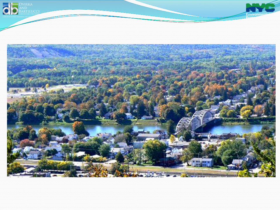
Location
� PJWWTP is located in Orange County NY adjacent to Delaware River on corner of NY, PA and NJ.
� PJWWTP is in Delaware Watershed for NYC DEP drinking water source.
� Delaware River Basin Commission (DRBC) jurisdiction.
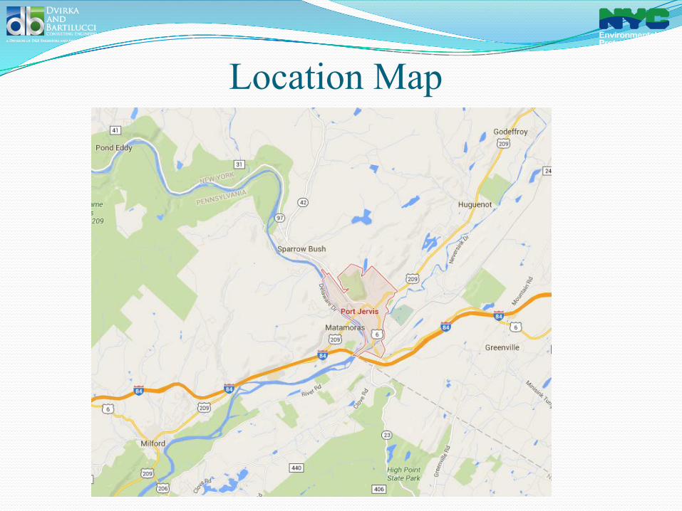
Location Map
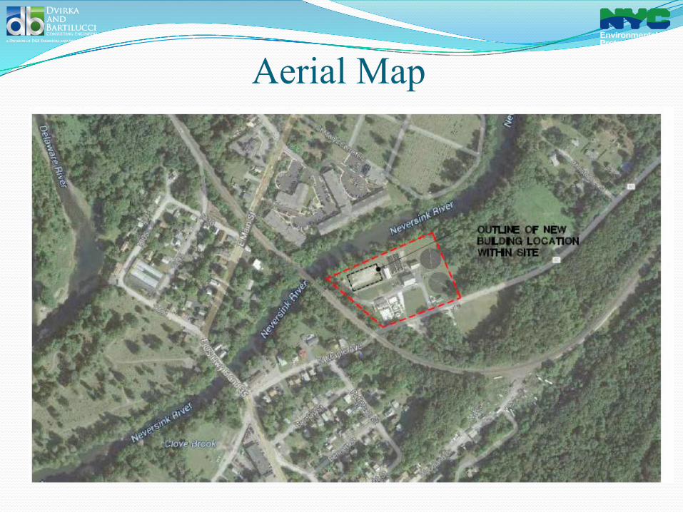
Aerial Map
Port Jervis WWTP - History
� 1931 – Supreme Court decreed that if NYC DEP diverts water from Delaware River – it has to construct wastewater treatment plant for City of Port Jervis
� 1946 – an agreement between NYC and City of Port Jervis was reached and subsequently later amended twice in the 1950s.
� 1947 - Design for Port Jervis WWTP began. � The facilities were required to serve population of 12,500 plus flow from
industrial facilities (equivalent population of 5,500).
Division of Responsibilities
� DEP constructed wastewater treatment plant, pump stations, interceptors and force mains.
� DEP maintains the wastewater treatment plant and the 3 pump stations.
� City of Port Jervis maintains the force mains and the interceptors.
Original Process Train
Trickling Filter No
2
Trickling Filter No
1
Final Settling Tanks
CCT
Admin. Building
3 Imhoff Tanks
Sludge Drying Beds
Subsequent Process Modifications
� 1985 - Sludge drying beds were abandoned and replaced with centrifuge.
� 1990s - Centrifuge was abandoned as it was not performing and replaced with liquid sludge removal off site.
� 2006 – Imhoff tanks were removed, and primary settling tanks constructed.
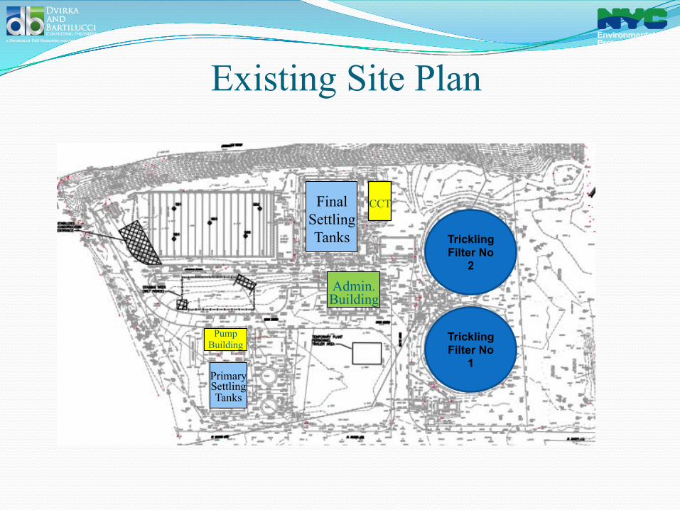
Existing Site Plan
Trickling Filter No
2
Trickling Filter No
1
Final Settling Tanks
CCT
Pump Building
Admin. Building
Primary Settling Tanks
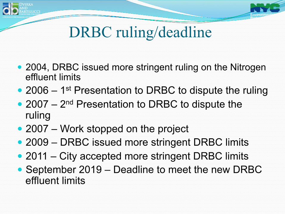
DRBC ruling/deadline
� 2004, DRBC issued more stringent ruling on the Nitrogen effluent limits
� 2006 – 1st Presentation to DRBC to dispute the ruling � 2007 – 2nd Presentation to DRBC to dispute the
ruling � 2007 – Work stopped on the project � 2009 – DRBC issued more stringent DRBC limits � 2011 – City accepted more stringent DRBC limits � September 2019 – Deadline to meet the new DRBC
effluent limits
Why Remove Nitrogen From The Delaware River?
� The rising concentration of harmful nutrient compounds leads to eutrophication (nutrient enrichment due to human activities) in surface waters.
� Summer algal blooms are a familiar example of this eutrophication, and can present problems for ecosystems and people alike: low dissolved oxygen, fish kills, murky water, and depletion of desirable flora and fauna.
� Current process does not remove total nitrogen (TN) and total phosphorus (TP) to the extent needed to protect receiving waters.

Existing Site Plan
Trickling Filter No
2
Trickling Filter No
1
Final Settling Tanks
CCT
Pump Building
Admin. Building
Primary Settling Tanks
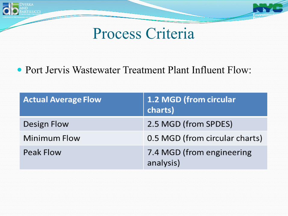
Process Criteria
� Port Jervis Wastewater Treatment Plant Influent Flow:
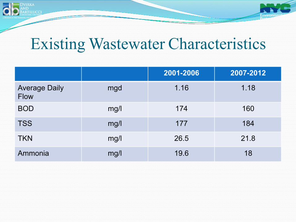
Existing Wastewater Characteristics 2001-2006 2007-2012
Average Daily Flow
mgd 1.16 1.18
BOD mg/l 174 160
TSS mg/l 177 184
TKN mg/l 26.5 21.8
Ammonia mg/l 19.6 18
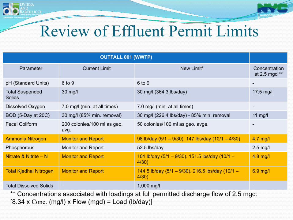
Review of Effluent Permit Limits
* DRBC Docket – effective 60 days after the completion of the upgrades or September 30, 2019 ** Concentrations associated with loadings at full permitted discharge flow of 2.5 mgd: [8.34 x Conc. (mg/l) x Flow (mgd) = Load (lb/day)]
OUTFALL 001 (WWTP)
Parameter Current Limit New Limit* Concentration at 2.5 mgd **
pH (Standard Units) 6 to 9 6 to 9 -
Total Suspended Solids
30 mg/l 30 mg/l (364.3 lbs/day) 17.5 mg/l
Dissolved Oxygen 7.0 mg/l (min. at all times) 7.0 mg/l (min. at all times) -
BOD (5-Day at 20C) 30 mg/l (85% min. removal) 30 mg/l (226.4 lbs/day) - 85% min. removal 11 mg/l
Fecal Coliform 200 colonies/100 ml as geo. avg.
50 colonies/100 ml as geo. avge. -
Ammonia Nitrogen Monitor and Report 98 lb/day (5/1 – 9/30). 147 lbs/day (10/1 – 4/30) 4.7 mg/l
Phosphorous Monitor and Report 52.5 lbs/day 2.5 mg/l
Nitrate & Nitrite – N Monitor and Report 101 lb/day (5/1 – 9/30). 151.5 lbs/day (10/1 – 4/30)
4.8 mg/l
Total Kjedhal Nitrogen Monitor and Report 144.5 lb/day (5/1 – 9/30). 216.5 lbs/day (10/1 – 4/30)
6.9 mg/l
Total Dissolved Solids - 1,000 mg/l -
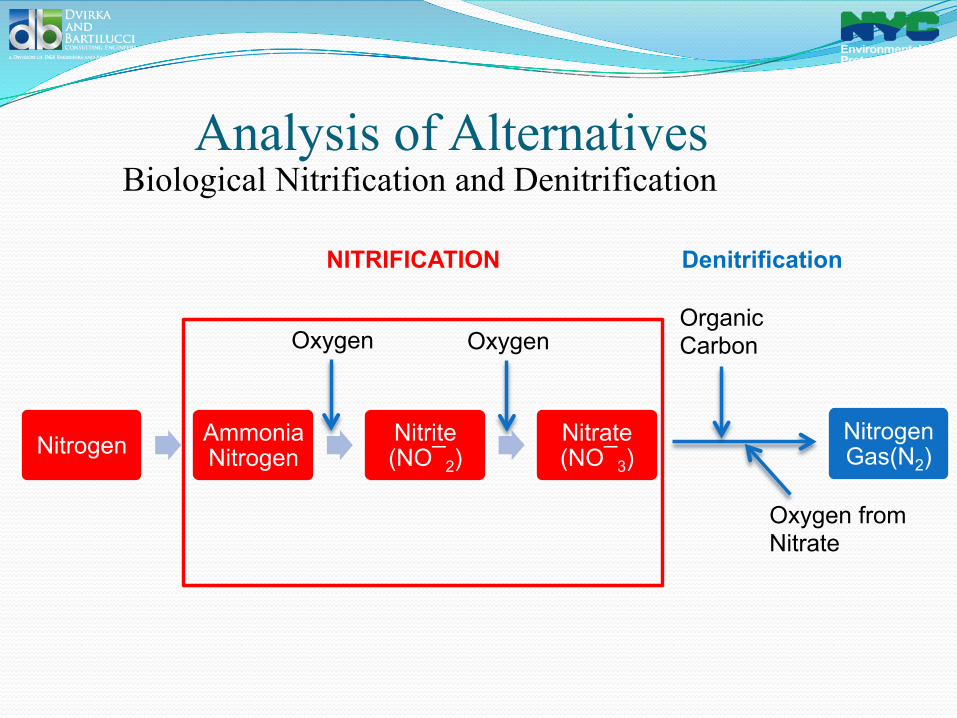
Analysis of Alternatives Biological Nitrification and Denitrification
Nitrogen Ammonia Nitrogen
Nitrite (NO¯2)
Nitrate (NO¯3)
Oxygen Oxygen
Nitrogen Gas(N2)
Organic Carbon
Denitrification NITRIFICATION
Oxygen from Nitrate
Limitations/Design Parameters
� Extreme weather conditions; high summer and very low winter temperatures.
� Reduced staff availability. Only 4 people on a full-time basis.
� Personnel is not trained for advanced treatment operation.
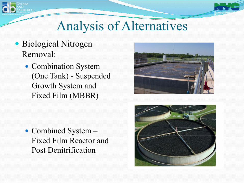
Analysis of Alternatives � Biological Nitrogen
Removal: � Combination System
(One Tank) - Suspended Growth System and Fixed Film (MBBR)
� Combined System –
Fixed Film Reactor and Post Denitrification
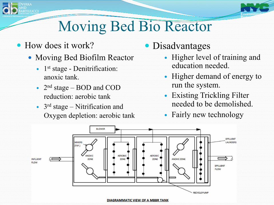
Moving Bed Bio Reactor � How does it work?
� Moving Bed Biofilm Reactor � 1st stage - Denitrification:
anoxic tank. � 2nd stage – BOD and COD
reduction: aerobic tank � 3rd stage – Nitrification and
Oxygen depletion: aerobic tank
� Disadvantages � Higher level of training and
education needed. � Higher demand of energy to
run the system. � Existing Trickling Filter
needed to be demolished. � Fairly new technology
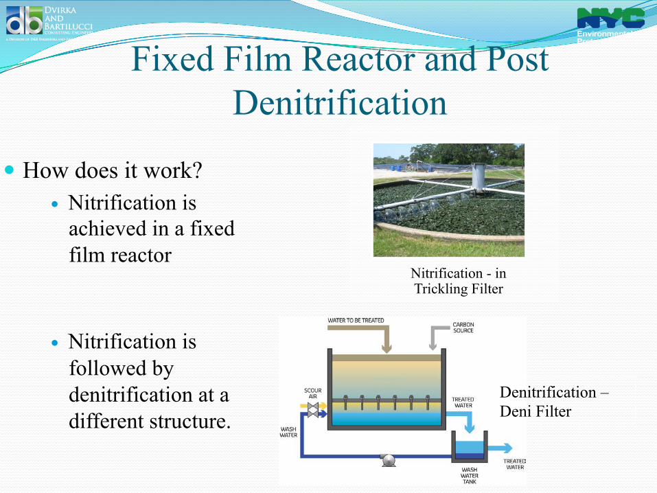
Fixed Film Reactor and Post Denitrification
� How does it work? � Nitrification is
achieved in a fixed film reactor
� Nitrification is followed by denitrification at a different structure.
Nitrification - in Trickling Filter
Denitrification – Deni Filter
Fixed Film Reactor
� Fixed Film Reactor Alternatives: � Rotating Biological Contactors � Deep Trickling Filters These processes are similar because both employ cultures of microorganisms that are attached to the surface of various media. For trickling filters the medium is stationary, whereas for rotary bio-contactors the medium, in the form of disks, rotates.
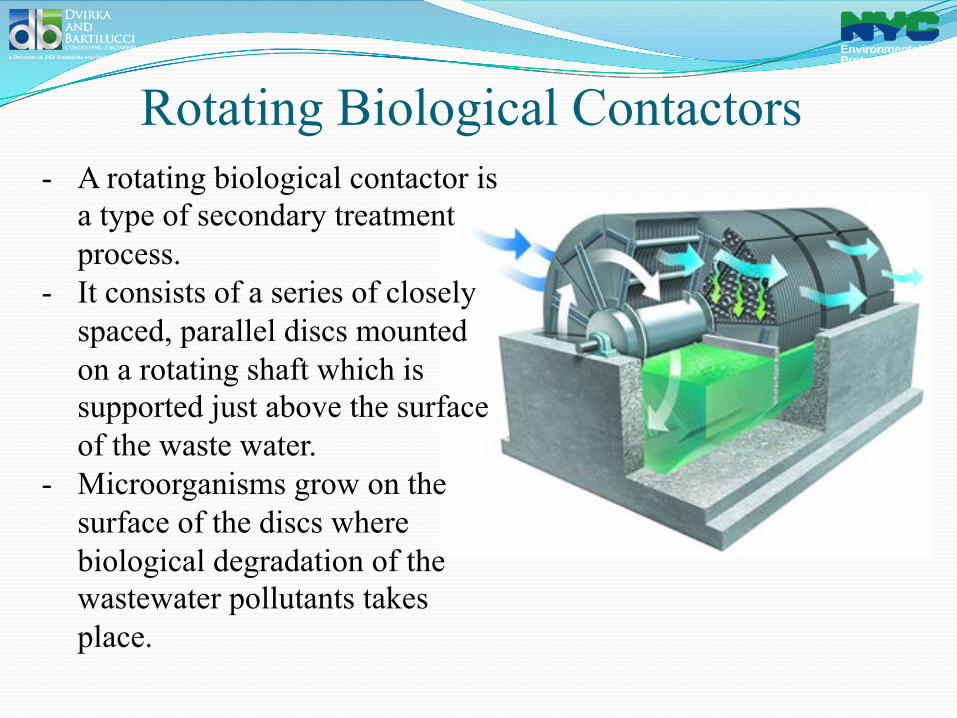
Rotating Biological Contactors - A rotating biological contactor is
a type of secondary treatment process.
- It consists of a series of closely spaced, parallel discs mounted on a rotating shaft which is supported just above the surface of the waste water.
- Microorganisms grow on the surface of the discs where biological degradation of the wastewater pollutants takes place.
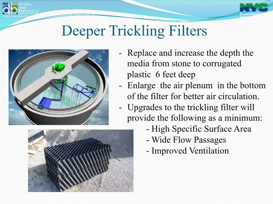
Deeper Trickling Filters - Replace and increase the depth the
media from stone to corrugated plastic 6 feet deep
- Enlarge the air plenum in the bottom of the filter for better air circulation.
- Upgrades to the trickling filter will provide the following as a minimum:
- High Specific Surface Area - Wide Flow Passages - Improved Ventilation
Post Denitrification
� Systems alternatives for denitrification
� Deep Sand Filters � Down-flow Mode � Up-flow mode
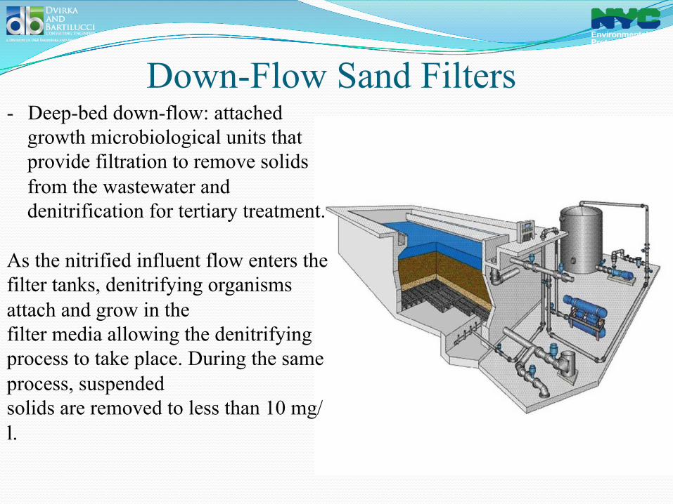
Down-Flow Sand Filters - Deep-bed down-flow: attached
growth microbiological units that provide filtration to remove solids from the wastewater and denitrification for tertiary treatment.
As the nitrified influent flow enters the filter tanks, denitrifying organisms attach and grow in the filter media allowing the denitrifying process to take place. During the same process, suspended solids are removed to less than 10 mg/l.
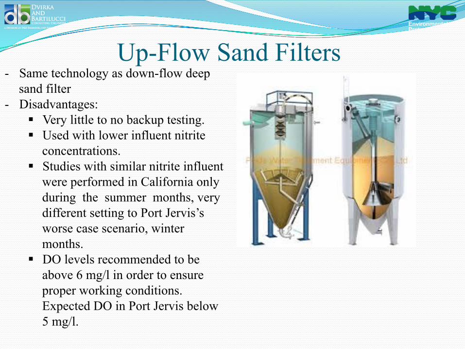
Up-Flow Sand Filters - Same technology as down-flow deep
sand filter - Disadvantages:
§ Very little to no backup testing. § Used with lower influent nitrite
concentrations. § Studies with similar nitrite influent
were performed in California only during the summer months, very different setting to Port Jervis’s worse case scenario, winter months.
§ DO levels recommended to be above 6 mg/l in order to ensure proper working conditions. Expected DO in Port Jervis below 5 mg/l.
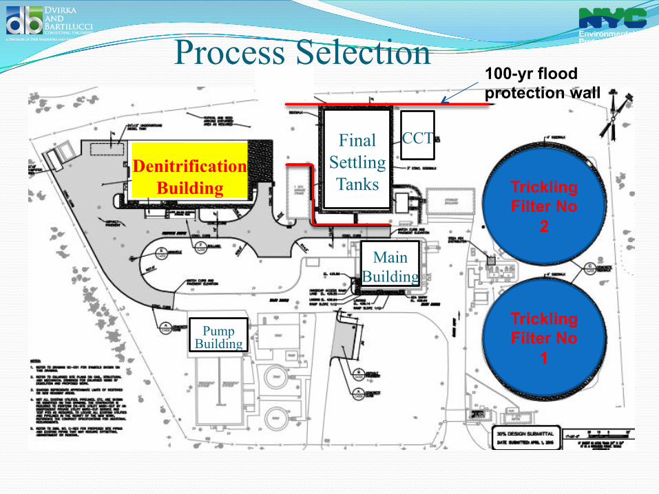
Process Selection
Denitrification Building
Final Settling Tanks Trickling
Filter No 2
Trickling Filter No
1
Main Building
CCT
Pump Building
100-yr flood protection wall

Process Selection � Nitrification
� Deep Trickling Filter
� Mechanical Distributor Arms � Process Air � Alkalinity Adjustment
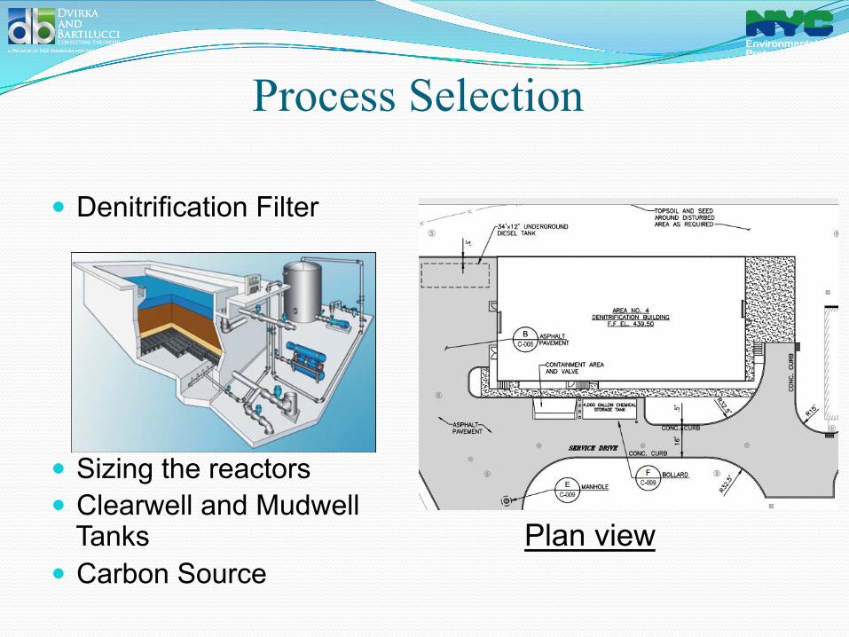
Process Selection
� Denitrification Filter
� Sizing the reactors � Clearwell and Mudwell
Tanks � Carbon Source
Plan view
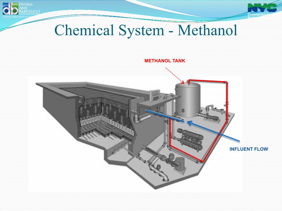
Chemical System - Methanol
METHANOL TANK
INFLUENT FLOW
Thank you
� Special Thank you to all DEP personnel involved with this project � Paul D. Smith, PE (Portfolio Manager) � Darin DeKoskie, PE (Accountable Manager) � Daniel Baumgardner – Plant Operator � BWS Staff – Matt Burd, Jim Fitzimmons PE, and Phil
Starks � D&B Design Team
Questions?
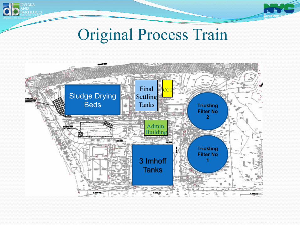
Original Process Train for WWTP
� The original process train for PJWWTP included: � 3 Imhoff tanks for primary settling, sludge digestion
and sludge storage � 2 Trickling Filters for biological treatment � 2 final settling tanks � Sludge drying beds enclosed with greenhouses