NWA 033627 001 40_System Maintenance Manual
126
System Maintenance Manual NWA-033627-001 ISSUE 4.0
-
Upload
gunawan-panasonic -
Category
Documents
-
view
27 -
download
15
description
setting nec
Transcript of NWA 033627 001 40_System Maintenance Manual
System Maintenance Manual
NWA-033627-001ISSUE 4.0
LIABILITY DISCLAIMER
NEC Corporation reserves the right to change the specifications,functions, or features, at any time, without notice.
NEC Corporation has prepared this document for use by its employ-ees and customers. The information contained herein is the propertyof NEC Corporation and shall not be reproduced without prior writtenapproval from NEC Corporation.
Dterm is a registered trademark of NEC Corporation.PCPro is a trademark of NEC Corporation.
Copyright 2010
NEC Corporation
i NWA-033627-001 Rev.4.095toc001.fm
TABLE OF CONTENTS
INTRODUCTIONPURPOSE ................................................................................................................ 1OUTLINE OF THIS MANUAL ................................................................................... 2TERMS IN THIS MANUAL ....................................................................................... 3
PBX System Designation ................................................................................................. 3Terminal Name ................................................................................................................ 3
REFERENCE MANUAL ........................................................................................... 5PRECAUTIONS ........................................................................................................ 6
System Data Backup ....................................................................................................... 6
Chapter 1 MAINTENANCE SERVICESHOW TO READ THIS CHAPTER ............................................................................ 1-2FAULT MESSAGE ................................................................................................... 1-3
General Description ......................................................................................................... 1-3Fault Message ............................................................................................................. 1-3External Alarm Display Panel ...................................................................................... 1-4
Service Conditions ........................................................................................................... 1-5Fault Message ............................................................................................................. 1-5External Alarm Display Panel ...................................................................................... 1-5
Programming Procedure .................................................................................................. 1-6Fault Message ............................................................................................................. 1-6External Alarm Display Panel ...................................................................................... 1-15
Operating Procedure ....................................................................................................... 1-15STATION LINE STATUS DISPLAY .......................................................................... 1-16
General Description ......................................................................................................... 1-16Service Conditions ........................................................................................................... 1-16Programming Procedure .................................................................................................. 1-16Operating Procedure ....................................................................................................... 1-16
BATTERY RELEASE CONTROL ............................................................................. 1-18General Description ......................................................................................................... 1-18Service Conditions ........................................................................................................... 1-18Programming Procedure .................................................................................................. 1-18Operating Procedure ....................................................................................................... 1-19
DIAGNOSTICS ......................................................................................................... 1-20General Description ......................................................................................................... 1-20Service Conditions ........................................................................................................... 1-20Programming Procedure .................................................................................................. 1-21Operating Procedure ....................................................................................................... 1-21
JULY/17/2009
ii NWA-033627-001 Rev.4.095toc001.fm
BATTERY REPLACEMENT ..................................................................................... 1-28FAULT REPORT SCHEDULING .............................................................................. 1-29
General Description ......................................................................................................... 1-29Service Conditions ........................................................................................................... 1-29Programming Procedure .................................................................................................. 1-30Operating Procedure ....................................................................................................... 1-31
VoIP LOG COLLECTION ......................................................................................... 1-32General Description ......................................................................................................... 1-32Service Conditions ........................................................................................................... 1-34Programming Procedure .................................................................................................. 1-42
QoS DISPLAY ON IP MULTILINE TERMINAL ........................................................ 1-46General Description ......................................................................................................... 1-46Service Conditions ........................................................................................................... 1-47Programming Procedure .................................................................................................. 1-47
STATION SERVICE STATUS DISPLAY .................................................................. 1-48General Description ......................................................................................................... 1-48Service Conditions ........................................................................................................... 1-48Programming Procedure .................................................................................................. 1-49
PING COMMAND ..................................................................................................... 1-52General Description ......................................................................................................... 1-52Service Conditions ........................................................................................................... 1-52Programming Procedure .................................................................................................. 1-55Operating Procedure ....................................................................................................... 1-56
Chapter 2 TROUBLESHOOTINGPRECAUTIONS ........................................................................................................ 2-2
Grounding Requirements ................................................................................................. 2-2Static Electricity Guard .................................................................................................... 2-3Turning Power ON ........................................................................................................... 2-6Turning Power OFF ......................................................................................................... 2-6
OUTLINE OF TROUBLESHOOTING ....................................................................... 2-7FAULT DETECTION ................................................................................................ 2-8
LED Indication on Blades ................................................................................................ 2-9FAULT INFORMATION DISPLAY ............................................................................ 2-12
Display on PCPro/CAT .................................................................................................... 2-12Fault Message ............................................................................................................. 2-12
Fault Diagnosis and Troubleshooting .............................................................................. 2-16Station Line Status Display ......................................................................................... 2-30
Troubleshooting by LED Indication on Blades ................................................................. 2-33Troubleshooting by Contents of Complaint ...................................................................... 2-37
Explanation of Symbols in Troubleshooting Procedure .............................................. 2-38How to Follow the “Tree” ............................................................................................. 2-38
JULY/17/2009
iii NWA-033627-001 Rev.4.095toc001.fm
Station Line Fault ........................................................................................................ 2-40C.O. Line/Tie Line Fault .............................................................................................. 2-42Power Failure Transfer (PFT) Fault ............................................................................ 2-51Digital Multiline Terminal Fault .................................................................................... 2-52IP Station Fault ............................................................................................................ 2-54DESKCON Fault ......................................................................................................... 2-56DSS Console Fault ...................................................................................................... 2-57
JULY/17/2009

iv NWA-033627-001 Rev.4.095toc001.fm
THIS PAGE LEFT BLANK INTENTIONALLY.
JULY/17/2009
INTRODUCTION
1 NWA-033627-001 Rev.4.095ch0001.fm
PURPOSE
INTRODUCTION
PURPOSE
This manual explains the maintenance services provided with the SV8300, and the recommended trouble-shooting procedure when a fault has occurred, for maintenance personnel of this system.
INTRODUCTION
2 NWA-033627-001 Rev.4.095ch0001.fm
OUTLINE OF THIS MANUAL
OUTLINE OF THIS MANUAL
This manual consists of two chapters. The following paragraphs summarize Chapters 1 and 2.
CHAPTER 1 MAINTENANCE SERVICESThis chapter describes the general description, service conditions, programming andoperating procedure of the maintenance services.
CHAPTER 2 TROUBLESHOOTINGThis chapter describes the precautions before troubleshooting, and the troubleshoot-ing procedure flow chart.
NOTE: For the following features, refer to the PC Programming Manual.• CPU Program Upgrade• System Data Save/Load/Verify
NOVEMBER/21/2008
INTRODUCTION
3 NWA-033627-001 Rev.4.095ch0001.fm
TERMS IN THIS MANUAL
TERMS IN THIS MANUAL
PBX System DesignationPBX system is designated as “PBX” or “system” usually.When we must draw a clear line between the PBX systems, they are designated as follows.SV8300: UNIVERGE SV8300
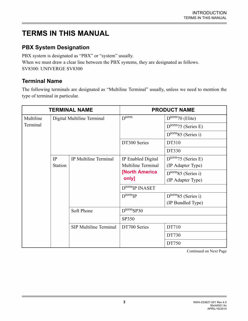
Terminal NameThe following terminals are designated as “Multiline Terminal” usually, unless we need to mention thetype of terminal in particular.
TERMINAL NAME PRODUCT NAMEMultiline Terminal
Digital Multiline Terminal Dterm Dterm70 (Elite)
Dterm75 (Series E)
Dterm85 (Series i)
DT300 Series DT310
DT330
IP Station
IP Multiline Terminal IP Enabled Digital Multiline Terminal[North America only]
Dterm75 (Series E)(IP Adapter Type)
Dterm85 (Series i)(IP Adapter Type)
DtermIP INASET
DtermIP Dterm85 (Series i)(IP Bundled Type)
Soft Phone DtermSP30
SP350
SIP Multiline Terminal DT700 Series DT710
DT730
DT750Continued on Next Page
APRIL/16/2010
INTRODUCTION
4 NWA-033627-001 Rev.4.095ch0001.fm
TERMS IN THIS MANUAL
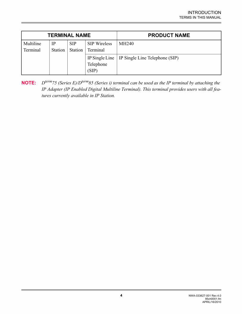
NOTE: Dterm75 (Series E)/Dterm85 (Series i) terminal can be used as the IP terminal by attaching the IP Adapter (IP Enabled Digital Multiline Terminal). This terminal provides users with all fea-tures currently available in IP Station.
TERMINAL NAME PRODUCT NAMEMultiline Terminal
IP Station
SIP Station
SIP Wireless Terminal
MH240
IP Single Line Telephone (SIP)
IP Single Line Telephone (SIP)
APRIL/16/2010
INTRODUCTION
5 NWA-033627-001 Rev.4.095ch0001.fm
REFERENCE MANUAL
REFERENCE MANUAL
Refer to the following manuals during maintenance and troubleshooting:
Command Manual:Contains the Customer Administration Terminal (CAT) operation, command functions and data re-quired for programming the system.
PC Programming Manual:Contains the functional description and the installation procedure for the PCPro.
System Hardware Manual:Contains the installation procedure for the PBX system and the hardware installation procedure forthe SV8300.
INTRODUCTION
6 NWA-033627-001 Rev.4.095ch0001.fm
PRECAUTIONS
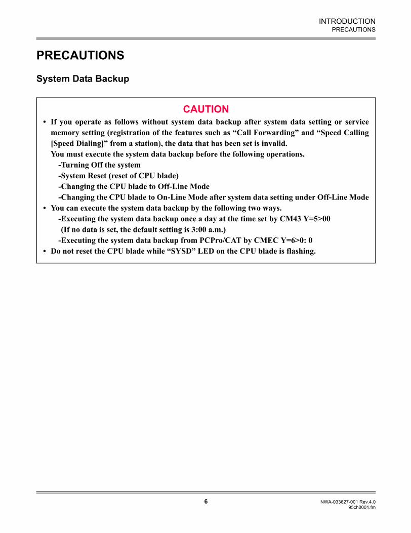
PRECAUTIONS
System Data Backup
CAUTION• If you operate as follows without system data backup after system data setting or service
memory setting (registration of the features such as “Call Forwarding” and “Speed Calling[Speed Dialing]” from a station), the data that has been set is invalid.You must execute the system data backup before the following operations.
-Turning Off the system-System Reset (reset of CPU blade)-Changing the CPU blade to Off-Line Mode-Changing the CPU blade to On-Line Mode after system data setting under Off-Line Mode
• You can execute the system data backup by the following two ways.-Executing the system data backup once a day at the time set by CM43 Y=5>00 (If no data is set, the default setting is 3:00 a.m.)-Executing the system data backup from PCPro/CAT by CMEC Y=6>0: 0
• Do not reset the CPU blade while “SYSD” LED on the CPU blade is flashing.
1-1 NWA-033627-001 Rev.4.095ch1001.fm
Chapter
1
UNIVERGE SV8300System Maintenance Manual
MAINTENANCE SERVICES
This chapter describes the general description, service conditions,programming and operating procedure of the maintenance services.
Chapter 1 MAINTENANCE SERVICES
1-2 NWA-033627-001 Rev.4.095ch1001.fm
HOW TO READ THIS CHAPTER
HOW TO READ THIS CHAPTER
In the programming procedure, the meaning of (1), (2) and marking are as follows:
(1): 1st Data
(2): 2nd Data
: DefaultWith the system data clear command (CM00, CM01), the data with this marking is automaticallyassigned for each command.
: Command with this marking can be used only under Off-Line mode of the CPUblade.To set Off-Line mode,(1) Set SENSE switch on the CPU blade to “E” or “F”.(2) Press RESET switch on the CPU blade.
OFF LINE
Chapter 1 MAINTENANCE SERVICES
1-3 NWA-033627-001 Rev.4.095ch1001.fm
FAULT MESSAGE
FAULT MESSAGE
General Description
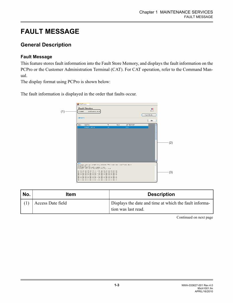
Fault MessageThis feature stores fault information into the Fault Store Memory, and displays the fault information on thePCPro or the Customer Administration Terminal (CAT). For CAT operation, refer to the Command Man-ual.The display format using PCPro is shown below:
The fault information is displayed in the order that faults occur.
Continued on next page
No. Item Description(1) Access Date field Displays the date and time at which the fault informa-
tion was last read.
(1)
(2)
(3)
APRIL/16/2010
Chapter 1 MAINTENANCE SERVICES
1-4 NWA-033627-001 Rev.4.095ch1001.fm
FAULT MESSAGE
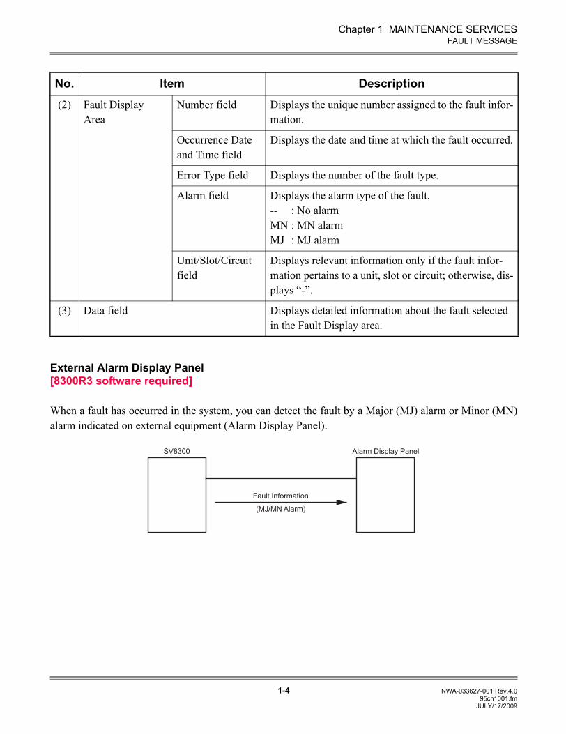
External Alarm Display Panel[8300R3 software required]
When a fault has occurred in the system, you can detect the fault by a Major (MJ) alarm or Minor (MN)alarm indicated on external equipment (Alarm Display Panel).
No. Item Description(2) Fault Display
AreaNumber field Displays the unique number assigned to the fault infor-
mation.
Occurrence Date and Time field
Displays the date and time at which the fault occurred.
Error Type field Displays the number of the fault type.
Alarm field Displays the alarm type of the fault.-- : No alarmMN : MN alarmMJ : MJ alarm
Unit/Slot/Circuit field
Displays relevant information only if the fault infor-mation pertains to a unit, slot or circuit; otherwise, dis-plays “-”.
(3) Data field Displays detailed information about the fault selected in the Fault Display area.
SV8300
(MJ/MN Alarm)
Alarm Display Panel
Fault Information
JULY/17/2009
Chapter 1 MAINTENANCE SERVICES
1-5 NWA-033627-001 Rev.4.095ch1001.fm
FAULT MESSAGE
Service Conditions
Fault Message(1) The maximum number of fault information that can be stored is 10.
(2) The alarm kind (Major Alarm, Minor Alarm or No Alarm Indication) can be programmed by CMEAY=2 or set by PCPro for each fault kind.
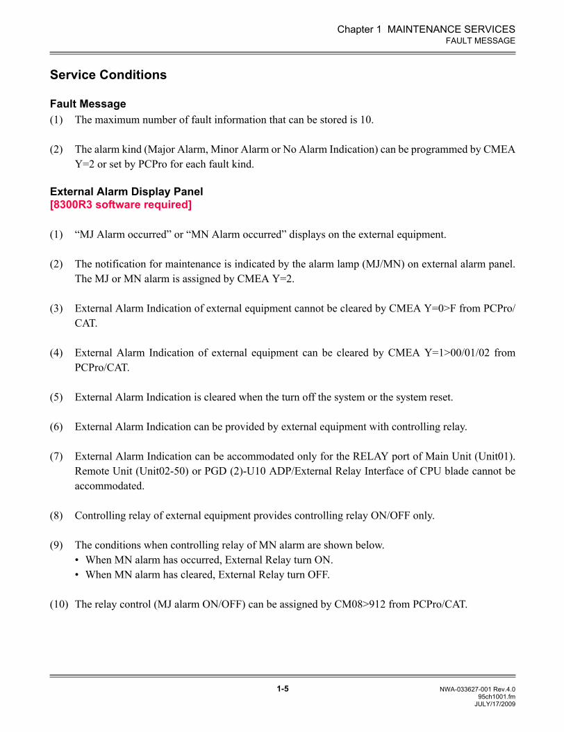
External Alarm Display Panel[8300R3 software required]
(1) “MJ Alarm occurred” or “MN Alarm occurred” displays on the external equipment.
(2) The notification for maintenance is indicated by the alarm lamp (MJ/MN) on external alarm panel.The MJ or MN alarm is assigned by CMEA Y=2.
(3) External Alarm Indication of external equipment cannot be cleared by CMEA Y=0>F from PCPro/CAT.
(4) External Alarm Indication of external equipment can be cleared by CMEA Y=1>00/01/02 fromPCPro/CAT.
(5) External Alarm Indication is cleared when the turn off the system or the system reset.
(6) External Alarm Indication can be provided by external equipment with controlling relay.
(7) External Alarm Indication can be accommodated only for the RELAY port of Main Unit (Unit01).Remote Unit (Unit02-50) or PGD (2)-U10 ADP/External Relay Interface of CPU blade cannot beaccommodated.
(8) Controlling relay of external equipment provides controlling relay ON/OFF only.
(9) The conditions when controlling relay of MN alarm are shown below.• When MN alarm has occurred, External Relay turn ON.• When MN alarm has cleared, External Relay turn OFF.
(10) The relay control (MJ alarm ON/OFF) can be assigned by CM08>912 from PCPro/CAT.
JULY/17/2009
Chapter 1 MAINTENANCE SERVICES
1-6 NWA-033627-001 Rev.4.095ch1001.fm
FAULT MESSAGE
Programming Procedure
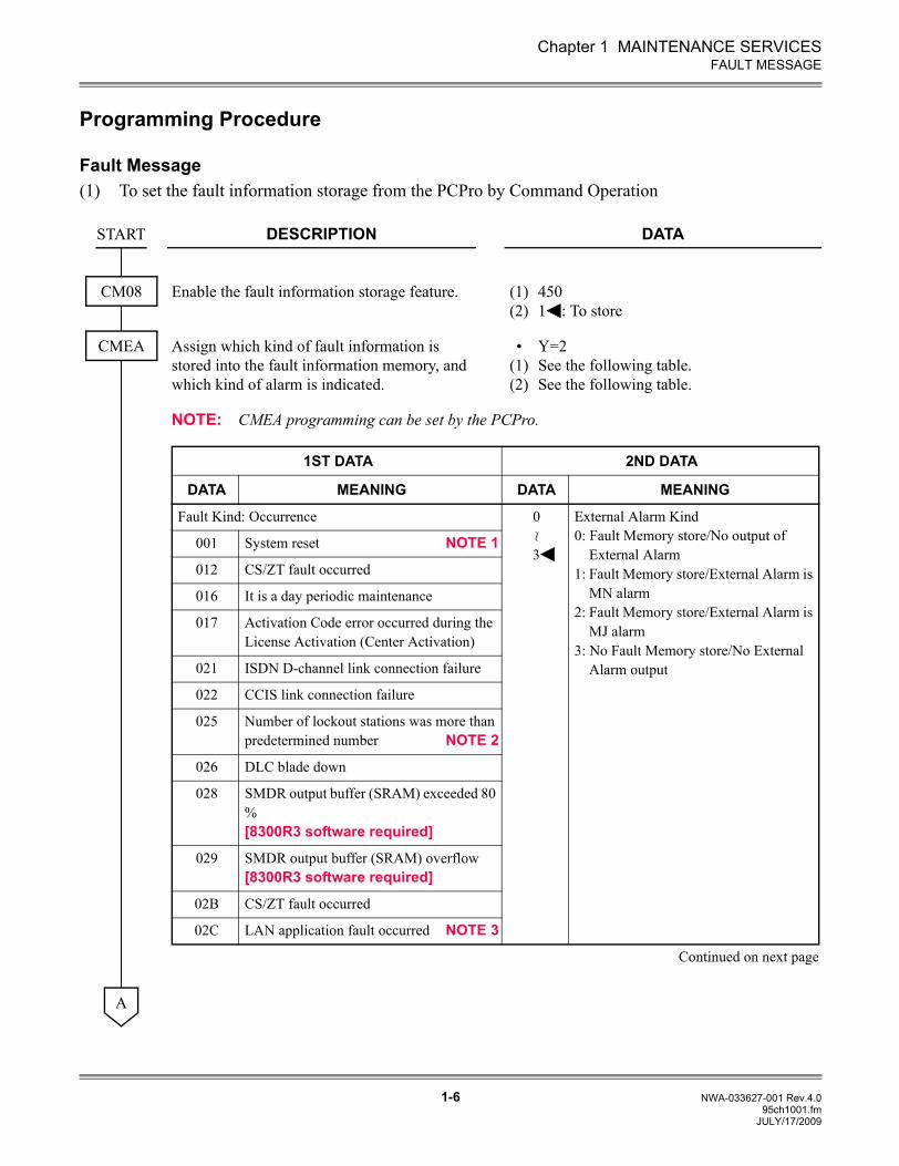
Fault Message(1) To set the fault information storage from the PCPro by Command Operation
DESCRIPTION DATA
Enable the fault information storage feature. (1)(2)
4501 : To store
Assign which kind of fault information is stored into the fault information memory, and which kind of alarm is indicated.
•(1)(2)
Y=2See the following table.See the following table.
NOTE: CMEA programming can be set by the PCPro.
START
CM08
CMEA
1ST DATA 2ND DATA
DATA MEANING DATA MEANING
Fault Kind: Occurrence 0
3
External Alarm Kind0: Fault Memory store/No output of
External Alarm1: Fault Memory store/External Alarm is
MN alarm2: Fault Memory store/External Alarm is
MJ alarm3: No Fault Memory store/No External
Alarm output
001 System reset NOTE 1
012 CS/ZT fault occurred
016 It is a day periodic maintenance
017 Activation Code error occurred during the License Activation (Center Activation)
021 ISDN D-channel link connection failure
022 CCIS link connection failure
025 Number of lockout stations was more than predetermined number NOTE 2
026 DLC blade down
028 SMDR output buffer (SRAM) exceeded 80 %[8300R3 software required]
029 SMDR output buffer (SRAM) overflow[8300R3 software required]
02B CS/ZT fault occurred
02C LAN application fault occurred NOTE 3
Continued on next page
~
A
JULY/17/2009
Chapter 1 MAINTENANCE SERVICES
1-7 NWA-033627-001 Rev.4.095ch1001.fm
FAULT MESSAGE
DESCRIPTION DATAA
CMEA 1ST DATA 2ND DATA
DATA MEANING DATA MEANING
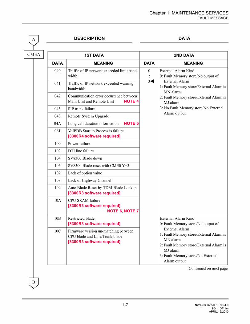
040 Traffic of IP network exceeded limit band-width
0
3
External Alarm Kind0: Fault Memory store/No output of
External Alarm1: Fault Memory store/External Alarm is
MN alarm2: Fault Memory store/External Alarm is
MJ alarm3: No Fault Memory store/No External
Alarm output
041 Traffic of IP network exceeded warning bandwidth
042 Communication error occurrence between Main Unit and Remote Unit NOTE 4
043 SIP trunk failure
048 Remote System Upgrade
04A Long call duration information NOTE 5
061 VoIPDB Startup Process is failure[8300R4 software required]
100 Power failure
102 DTI line failure
104 SV8300 Blade down
106 SV8300 Blade reset with CME0 Y=3
107 Lack of option value
108 Lack of Highway Channel
109 Auto Blade Reset by TDM-Blade Lockup[8300R3 software required]
10A CPU SRAM failure[8300R3 software required]
NOTE 6, NOTE 7
10B Restricted blade[8300R3 software required]
External Alarm Kind0: Fault Memory store/No output of
External Alarm1: Fault Memory store/External Alarm is
MN alarm2: Fault Memory store/External Alarm is
MJ alarm3: Fault Memory store/No External
Alarm output
10C Firmware version un-matching between CPU blade and Line/Trunk blade[8300R3 software required]
Continued on next page
~
B
APRIL/16/2010
Chapter 1 MAINTENANCE SERVICES
1-8 NWA-033627-001 Rev.4.095ch1001.fm
FAULT MESSAGE
DESCRIPTION DATAB
CMEA 1ST DATA 2ND DATA
DATA MEANING DATA MEANING
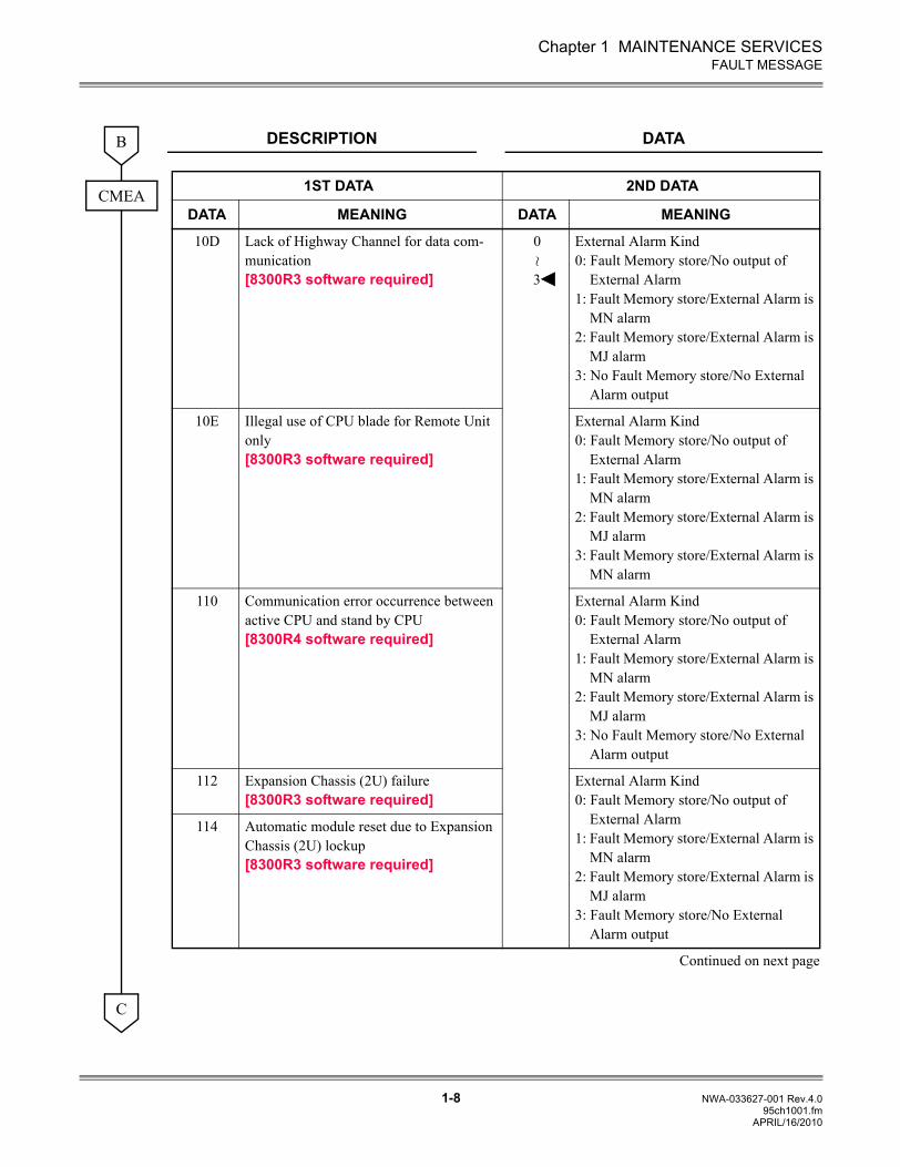
10D Lack of Highway Channel for data com-munication[8300R3 software required]
0
3
External Alarm Kind0: Fault Memory store/No output of
External Alarm1: Fault Memory store/External Alarm is
MN alarm2: Fault Memory store/External Alarm is
MJ alarm3: No Fault Memory store/No External
Alarm output
10E Illegal use of CPU blade for Remote Unit only[8300R3 software required]
External Alarm Kind0: Fault Memory store/No output of
External Alarm1: Fault Memory store/External Alarm is
MN alarm2: Fault Memory store/External Alarm is
MJ alarm3: Fault Memory store/External Alarm is
MN alarm
110 Communication error occurrence between active CPU and stand by CPU[8300R4 software required]
External Alarm Kind0: Fault Memory store/No output of
External Alarm1: Fault Memory store/External Alarm is
MN alarm2: Fault Memory store/External Alarm is
MJ alarm3: No Fault Memory store/No External
Alarm output
112 Expansion Chassis (2U) failure[8300R3 software required]
External Alarm Kind0: Fault Memory store/No output of
External Alarm1: Fault Memory store/External Alarm is
MN alarm2: Fault Memory store/External Alarm is
MJ alarm3: Fault Memory store/No External
Alarm output
114 Automatic module reset due to Expansion Chassis (2U) lockup[8300R3 software required]
Continued on next page
~
C
APRIL/16/2010
Chapter 1 MAINTENANCE SERVICES
1-9 NWA-033627-001 Rev.4.095ch1001.fm
FAULT MESSAGE
DESCRIPTION DATAC
CMEA 1ST DATA 2ND DATA
DATA MEANING DATA MEANING
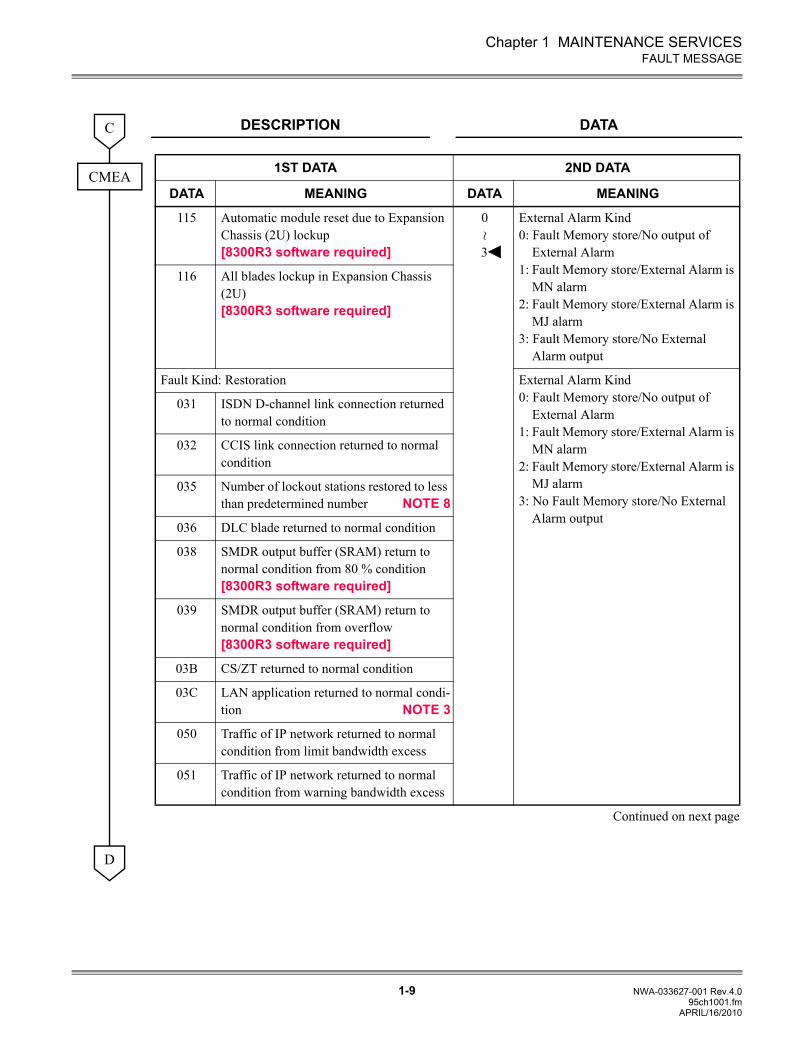
115 Automatic module reset due to Expansion Chassis (2U) lockup[8300R3 software required]
0
3
External Alarm Kind0: Fault Memory store/No output of
External Alarm1: Fault Memory store/External Alarm is
MN alarm2: Fault Memory store/External Alarm is
MJ alarm3: Fault Memory store/No External
Alarm output
116 All blades lockup in Expansion Chassis (2U)[8300R3 software required]
Fault Kind: Restoration External Alarm Kind0: Fault Memory store/No output of
External Alarm1: Fault Memory store/External Alarm is
MN alarm2: Fault Memory store/External Alarm is
MJ alarm3: No Fault Memory store/No External
Alarm output
031 ISDN D-channel link connection returned to normal condition
032 CCIS link connection returned to normal condition
035 Number of lockout stations restored to less than predetermined number NOTE 8
036 DLC blade returned to normal condition
038 SMDR output buffer (SRAM) return to normal condition from 80 % condition[8300R3 software required]
039 SMDR output buffer (SRAM) return to normal condition from overflow[8300R3 software required]
03B CS/ZT returned to normal condition
03C LAN application returned to normal condi-tion NOTE 3
050 Traffic of IP network returned to normal condition from limit bandwidth excess
051 Traffic of IP network returned to normal condition from warning bandwidth excess
Continued on next page
~
D
APRIL/16/2010
Chapter 1 MAINTENANCE SERVICES
1-10 NWA-033627-001 Rev.4.095ch1001.fm
FAULT MESSAGE
DESCRIPTION DATA
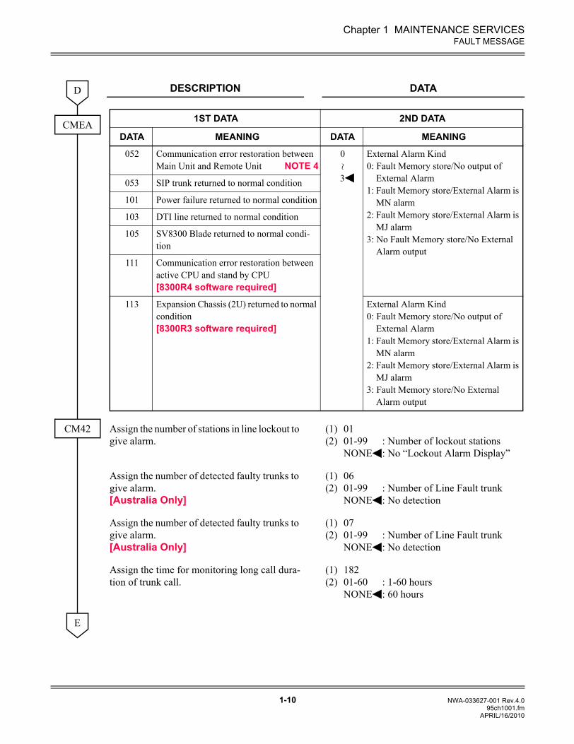
Assign the number of stations in line lockout to give alarm.
(1)(2)
0101-99 : Number of lockout stationsNONE : No “Lockout Alarm Display”
Assign the number of detected faulty trunks to give alarm.[Australia Only]
(1)(2)
0601-99 : Number of Line Fault trunkNONE : No detection
Assign the number of detected faulty trunks to give alarm.[Australia Only]
(1)(2)
0701-99 : Number of Line Fault trunkNONE : No detection
Assign the time for monitoring long call dura-tion of trunk call.
(1)(2)
18201-60 : 1-60 hoursNONE : 60 hours
D
CMEA 1ST DATA 2ND DATA
DATA MEANING DATA MEANING
052 Communication error restoration between Main Unit and Remote Unit NOTE 4
0
3
External Alarm Kind0: Fault Memory store/No output of
External Alarm1: Fault Memory store/External Alarm is
MN alarm2: Fault Memory store/External Alarm is
MJ alarm3: No Fault Memory store/No External
Alarm output
053 SIP trunk returned to normal condition
101 Power failure returned to normal condition
103 DTI line returned to normal condition
105 SV8300 Blade returned to normal condi-tion
111 Communication error restoration between active CPU and stand by CPU[8300R4 software required]
113 Expansion Chassis (2U) returned to normal condition[8300R3 software required]
External Alarm Kind0: Fault Memory store/No output of
External Alarm1: Fault Memory store/External Alarm is
MN alarm2: Fault Memory store/External Alarm is
MJ alarm3: Fault Memory store/No External
Alarm output
~
CM42
E
APRIL/16/2010
Chapter 1 MAINTENANCE SERVICES
1-11 NWA-033627-001 Rev.4.095ch1001.fm
FAULT MESSAGE
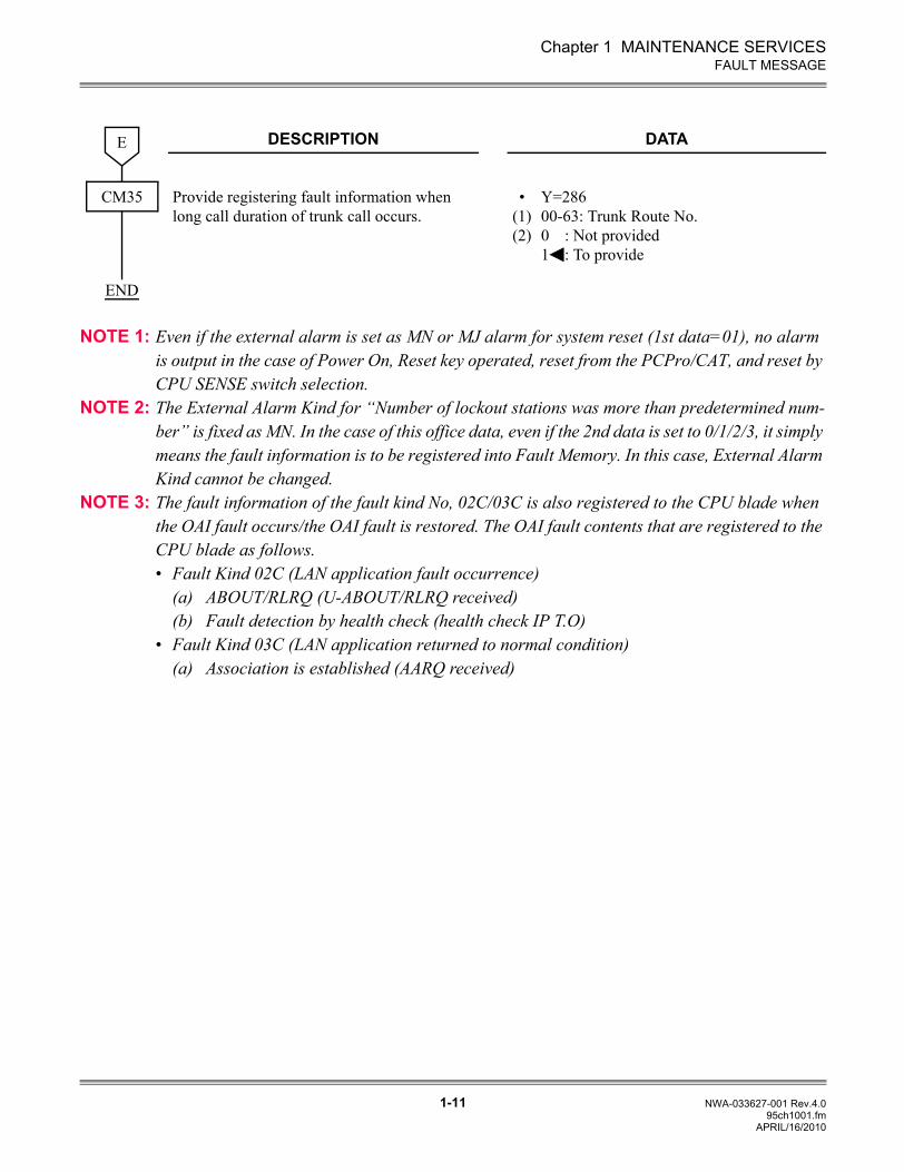
NOTE 1: Even if the external alarm is set as MN or MJ alarm for system reset (1st data=01), no alarm is output in the case of Power On, Reset key operated, reset from the PCPro/CAT, and reset by CPU SENSE switch selection.
NOTE 2: The External Alarm Kind for “Number of lockout stations was more than predetermined num-ber” is fixed as MN. In the case of this office data, even if the 2nd data is set to 0/1/2/3, it simply means the fault information is to be registered into Fault Memory. In this case, External Alarm Kind cannot be changed.
NOTE 3: The fault information of the fault kind No, 02C/03C is also registered to the CPU blade when the OAI fault occurs/the OAI fault is restored. The OAI fault contents that are registered to the CPU blade as follows.• Fault Kind 02C (LAN application fault occurrence)
(a) ABOUT/RLRQ (U-ABOUT/RLRQ received)(b) Fault detection by health check (health check IP T.O)
• Fault Kind 03C (LAN application returned to normal condition)(a) Association is established (AARQ received)
DESCRIPTION DATA
Provide registering fault information when long call duration of trunk call occurs.
•(1)(2)
Y=28600-63: Trunk Route No.0 : Not provided1 : To provide
E
CM35
END
APRIL/16/2010
Chapter 1 MAINTENANCE SERVICES
1-12 NWA-033627-001 Rev.4.095ch1001.fm
FAULT MESSAGE
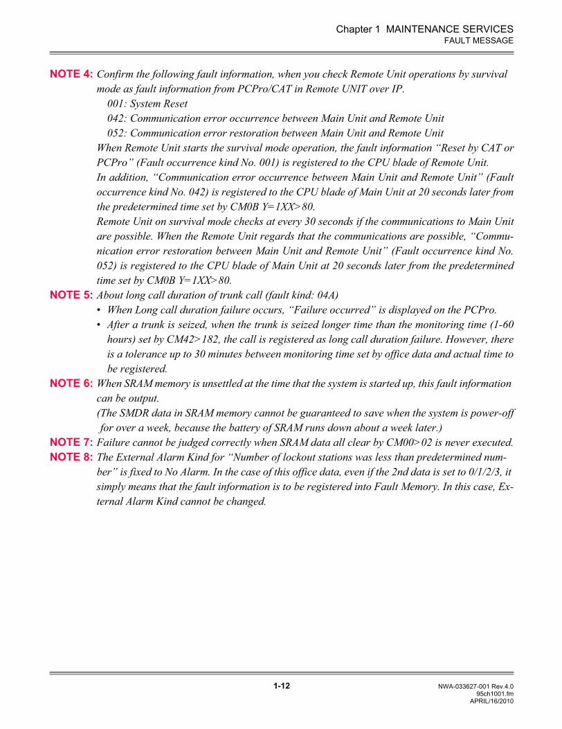
NOTE 4: Confirm the following fault information, when you check Remote Unit operations by survival mode as fault information from PCPro/CAT in Remote UNIT over IP.
001: System Reset042: Communication error occurrence between Main Unit and Remote Unit052: Communication error restoration between Main Unit and Remote Unit
When Remote Unit starts the survival mode operation, the fault information “Reset by CAT orPCPro” (Fault occurrence kind No. 001) is registered to the CPU blade of Remote Unit. In addition, “Communication error occurrence between Main Unit and Remote Unit” (Faultoccurrence kind No. 042) is registered to the CPU blade of Main Unit at 20 seconds later fromthe predetermined time set by CM0B Y=1XX>80.Remote Unit on survival mode checks at every 30 seconds if the communications to Main Unitare possible. When the Remote Unit regards that the communications are possible, “Commu-nication error restoration between Main Unit and Remote Unit” (Fault occurrence kind No.052) is registered to the CPU blade of Main Unit at 20 seconds later from the predeterminedtime set by CM0B Y=1XX>80.
NOTE 5: About long call duration of trunk call (fault kind: 04A)• When Long call duration failure occurs, “Failure occurred” is displayed on the PCPro.• After a trunk is seized, when the trunk is seized longer time than the monitoring time (1-60
hours) set by CM42>182, the call is registered as long call duration failure. However, thereis a tolerance up to 30 minutes between monitoring time set by office data and actual time tobe registered.
NOTE 6: When SRAM memory is unsettled at the time that the system is started up, this fault information can be output.(The SMDR data in SRAM memory cannot be guaranteed to save when the system is power-offfor over a week, because the battery of SRAM runs down about a week later.)
NOTE 7: Failure cannot be judged correctly when SRAM data all clear by CM00>02 is never executed.NOTE 8: The External Alarm Kind for “Number of lockout stations was less than predetermined num-
ber” is fixed to No Alarm. In the case of this office data, even if the 2nd data is set to 0/1/2/3, it simply means that the fault information is to be registered into Fault Memory. In this case, Ex-ternal Alarm Kind cannot be changed.
APRIL/16/2010
Chapter 1 MAINTENANCE SERVICES
1-13 NWA-033627-001 Rev.4.095ch1001.fm
FAULT MESSAGE
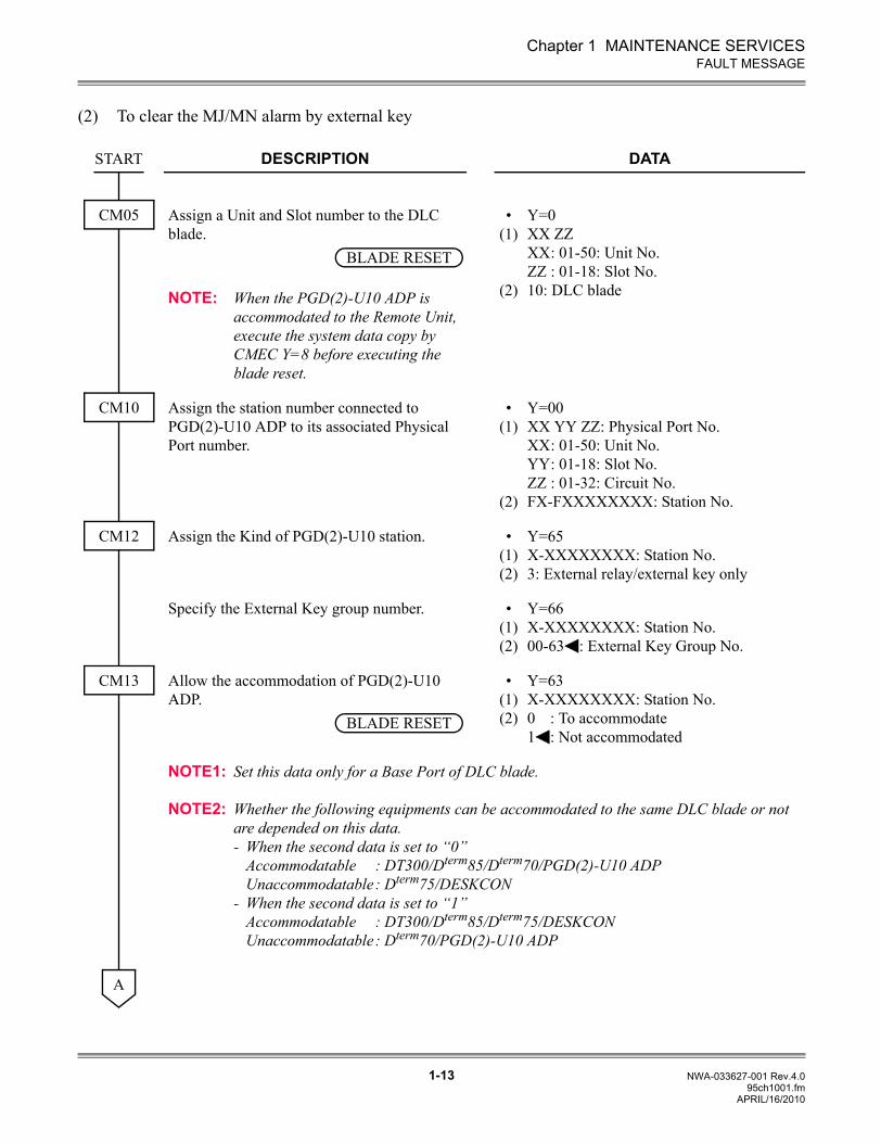
(2) To clear the MJ/MN alarm by external key
DESCRIPTION DATA
Assign a Unit and Slot number to the DLC blade.
NOTE: When the PGD(2)-U10 ADP is accommodated to the Remote Unit, execute the system data copy by CMEC Y=8 before executing the blade reset.
•(1)
(2)
Y=0XX ZZXX: 01-50: Unit No.ZZ : 01-18: Slot No.10: DLC blade
Assign the station number connected to PGD(2)-U10 ADP to its associated Physical Port number.
•(1)
(2)
Y=00XX YY ZZ: Physical Port No.XX: 01-50: Unit No.YY: 01-18: Slot No.ZZ : 01-32: Circuit No.FX-FXXXXXXXX: Station No.
Assign the Kind of PGD(2)-U10 station. •(1)(2)
Y=65X-XXXXXXXX: Station No.3: External relay/external key only
Specify the External Key group number. •(1)(2)
Y=66X-XXXXXXXX: Station No.00-63 : External Key Group No.
Allow the accommodation of PGD(2)-U10 ADP.
•(1)(2)
Y=63X-XXXXXXXX: Station No.0 : To accommodate 1 : Not accommodated
NOTE1: Set this data only for a Base Port of DLC blade.
NOTE2: Whether the following equipments can be accommodated to the same DLC blade or not are depended on this data.- When the second data is set to “0”
Accommodatable : DT300/Dterm85/Dterm70/PGD(2)-U10 ADPUnaccommodatable: Dterm75/DESKCON
- When the second data is set to “1”Accommodatable : DT300/Dterm85/Dterm75/DESKCONUnaccommodatable: Dterm70/PGD(2)-U10 ADP
START
CM05
BLADE RESET
CM10
CM12
CM13
BLADE RESET
A
APRIL/16/2010
Chapter 1 MAINTENANCE SERVICES
1-14 NWA-033627-001 Rev.4.095ch1001.fm
FAULT MESSAGE
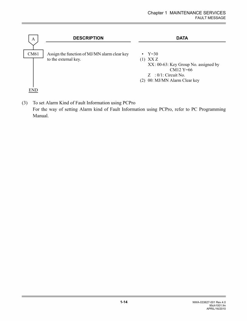
(3) To set Alarm Kind of Fault Information using PCProFor the way of setting Alarm kind of Fault Information using PCPro, refer to PC ProgrammingManual.
DESCRIPTION DATA
Assign the function of MJ/MN alarm clear key to the external key.
•(1)
(2)
Y=30 XX ZXX: 00-63: Key Group No. assigned by
CM12 Y=66Z : 0/1: Circuit No.00: MJ/MN Alarm Clear key
A
CM61
END
APRIL/16/2010
Chapter 1 MAINTENANCE SERVICES
1-15 NWA-033627-001 Rev.4.095ch1001.fm
FAULT MESSAGE
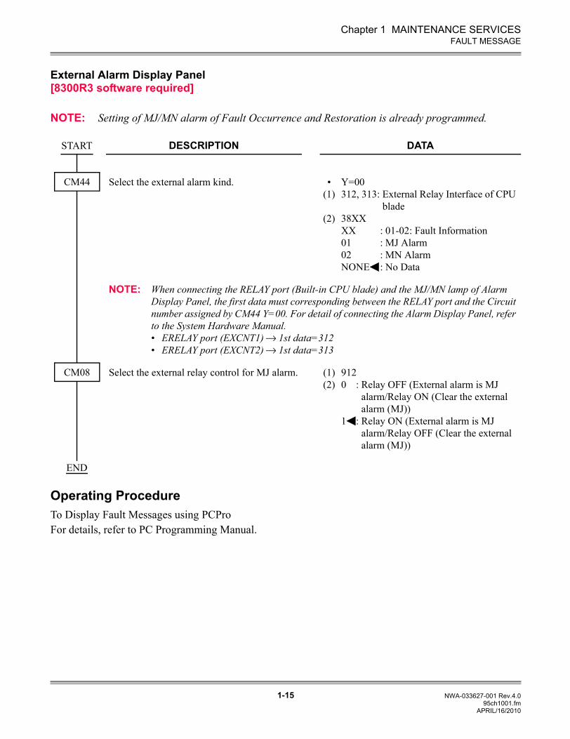
External Alarm Display Panel[8300R3 software required]
NOTE: Setting of MJ/MN alarm of Fault Occurrence and Restoration is already programmed.
Operating ProcedureTo Display Fault Messages using PCProFor details, refer to PC Programming Manual.
DESCRIPTION DATA
Select the external alarm kind. •(1)
(2)
Y=00312, 313: External Relay Interface of CPU
blade38XXXX : 01-02: Fault Information01 : MJ Alarm02 : MN AlarmNONE : No Data
NOTE: When connecting the RELAY port (Built-in CPU blade) and the MJ/MN lamp of Alarm Display Panel, the first data must corresponding between the RELAY port and the Circuit number assigned by CM44 Y=00. For detail of connecting the Alarm Display Panel, refer to the System Hardware Manual.• ERELAY port (EXCNT1) 1st data=312• ERELAY port (EXCNT2) 1st data=313
Select the external relay control for MJ alarm. (1)(2)
9120 : Relay OFF (External alarm is MJ
alarm/Relay ON (Clear the external alarm (MJ))
1 : Relay ON (External alarm is MJ alarm/Relay OFF (Clear the external alarm (MJ))
START
CM44
CM08
END
APRIL/16/2010
Chapter 1 MAINTENANCE SERVICES
1-16 NWA-033627-001 Rev.4.095ch1001.fm
STATION LINE STATUS DISPLAY
STATION LINE STATUS DISPLAY
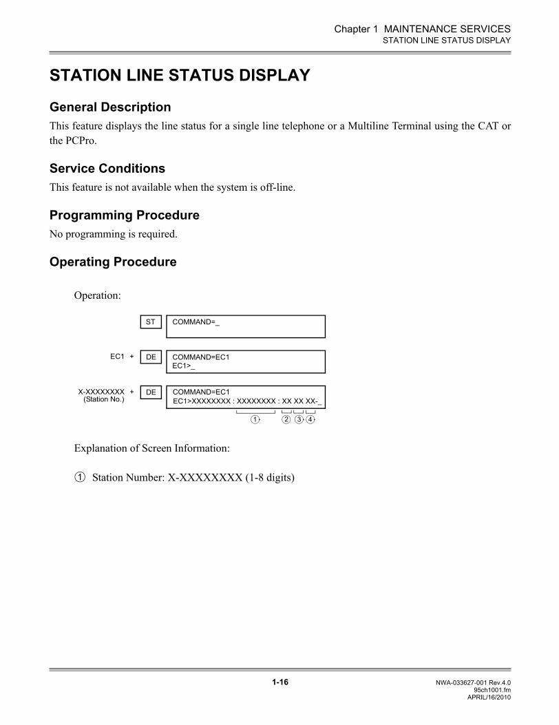
General DescriptionThis feature displays the line status for a single line telephone or a Multiline Terminal using the CAT orthe PCPro.
Service ConditionsThis feature is not available when the system is off-line.
Programming ProcedureNo programming is required.
Operating Procedure
Operation:
Explanation of Screen Information:
Station Number: X-XXXXXXXX (1-8 digits)
EC1 DE+
ST COMMAND=_
X-XXXXXXXX DE+EC1>XXXXXXXX : XXXXXXXX : XX XX XX-_(Station No.)
41 3
COMMAND=EC1EC1>_
COMMAND=EC1
2
1
APRIL/16/2010
Chapter 1 MAINTENANCE SERVICES
1-17 NWA-033627-001 Rev.4.095ch1001.fm
STATION LINE STATUS DISPLAY
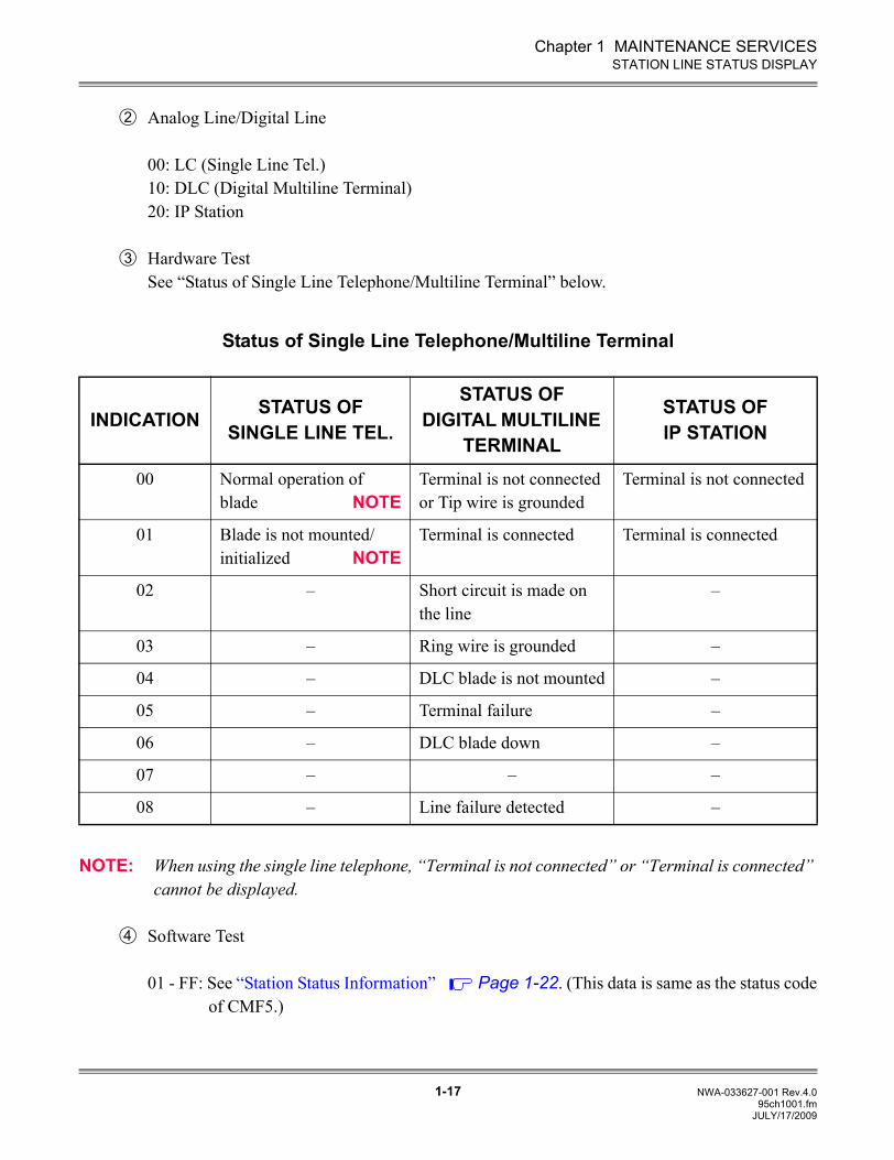
Analog Line/Digital Line
00: LC (Single Line Tel.)10: DLC (Digital Multiline Terminal)20: IP Station
Hardware TestSee “Status of Single Line Telephone/Multiline Terminal” below.
Status of Single Line Telephone/Multiline Terminal
NOTE: When using the single line telephone, “Terminal is not connected” or “Terminal is connected” cannot be displayed.
Software Test
01 - FF: See “Station Status Information” Page 1-22. (This data is same as the status codeof CMF5.)
INDICATION STATUS OF SINGLE LINE TEL.
STATUS OF DIGITAL MULTILINE
TERMINAL
STATUS OF IP STATION
00 Normal operation of blade NOTE
Terminal is not connected or Tip wire is grounded
Terminal is not connected
01 Blade is not mounted/initialized NOTE
Terminal is connected Terminal is connected
02 – Short circuit is made on the line
–
03 – Ring wire is grounded –
04 – DLC blade is not mounted –
05 – Terminal failure –
06 – DLC blade down –
07 – – –
08 – Line failure detected –
2
3
4
JULY/17/2009
Chapter 1 MAINTENANCE SERVICES
1-18 NWA-033627-001 Rev.4.095ch1001.fm
BATTERY RELEASE CONTROL
BATTERY RELEASE CONTROL
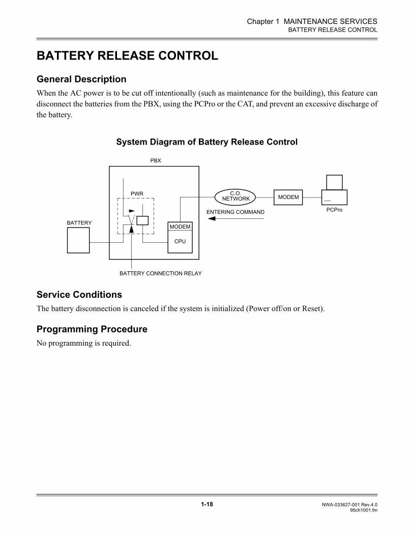
General DescriptionWhen the AC power is to be cut off intentionally (such as maintenance for the building), this feature candisconnect the batteries from the PBX, using the PCPro or the CAT, and prevent an excessive discharge ofthe battery.
System Diagram of Battery Release Control
Service ConditionsThe battery disconnection is canceled if the system is initialized (Power off/on or Reset).
Programming ProcedureNo programming is required.
PCPro
MODEMC.O.
NETWORK
ENTERING COMMAND
PBX
MODEM
CPU
BATTERY CONNECTION RELAY
PWR
BATTERY
Chapter 1 MAINTENANCE SERVICES
1-19 NWA-033627-001 Rev.4.095ch1001.fm
BATTERY RELEASE CONTROL
Operating Procedure
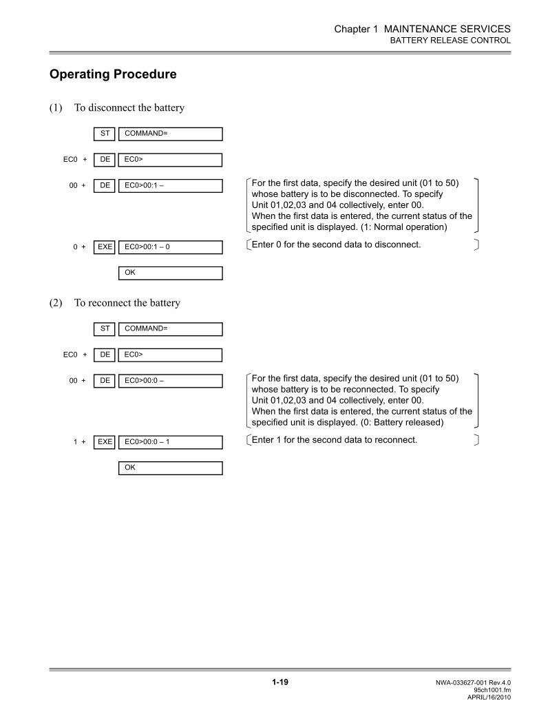
(1) To disconnect the battery
(2) To reconnect the battery
DE+ EC0>EC0
ST COMMAND=
DE+ EC0>00:1 –00
EXE+ EC0>00:1 – 00
OK
For the first data, specify the desired unit (01 to 50) whose battery is to be disconnected. To specify Unit 01,02,03 and 04 collectively, enter 00.When the first data is entered, the current status of the specified unit is displayed. (1: Normal operation)
Enter 0 for the second data to disconnect.
DE+ EC0>EC0
ST COMMAND=
DE+ EC0>00:0 –00
EXE+ EC0>00:0 – 11
OK
For the first data, specify the desired unit (01 to 50) whose battery is to be reconnected. To specify Unit 01,02,03 and 04 collectively, enter 00.When the first data is entered, the current status of the specified unit is displayed. (0: Battery released)
Enter 1 for the second data to reconnect.
APRIL/16/2010
Chapter 1 MAINTENANCE SERVICES
1-20 NWA-033627-001 Rev.4.095ch1001.fm
DIAGNOSTICS
DIAGNOSTICS
General DescriptionTo assist maintenance personnel, this feature provides diagnostic capabilities such as fault code genera-tion, device status information and alarm information recording, which can be accessed from the PCProor the CAT.
Service Conditions
(1) The following station status information can be displayed on the PCPro or the CAT by directcommand:
• Idle• Line Lockout• Dialing• Tone Trunk Connection (reorder tone, busy tone, service set tone, etc.)• Types of Connection (station-to-station, three-way calling, voice calling, holding, etc.)• Destination number (trunk number, register number)• Short circuit on line
(2) The following trunk status information can be displayed on the PCPro or the CAT by directcommand:
• Idle• Ringing in• Incoming queue to Attendant Console• Holding• In a tandem connection• Incoming queue to UCD• Dialing• Receiving dialed digits
Chapter 1 MAINTENANCE SERVICES
1-21 NWA-033627-001 Rev.4.095ch1001.fm
DIAGNOSTICS
(3) The following information is stored and can be displayed on the PCPro or the CAT using a memorydump command in hexadecimal format:
• Program address where an endless loop has occurred• Last reset time for main program• Last reset time for firmware program• The reason for reset (power-on, RESET key, endless loop, rotary switch, command from PCPro or
CAT)
(4) The PBX has a built-in patrol program that monitors the status of all connected devices. Additionally,when no response or an invalid response from a device is received, this program stores in memorythe slot number of that device. From the PCPro or the CAT, a maintenance person can read the slotnumber of any device which does not respond to the main processor or provides an illegal status tothe main processor.
Programming ProcedureNo programming is required.
Operating Procedure
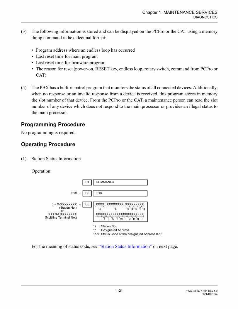
(1) Station Status Information
Operation:
For the meaning of status code, see “Station Status Information” on next page.
DE+ F50>F50
ST COMMAND=
DE+ XXXX : XXXXXXXX XXXXXXXXX0 + X-XXXXXXXX(Station No.)or
0 + FX-FXXXXXXXX(Multiline Terminal No.)
*a *b *c *d *e *f *g
XXXXXXXXXXXXXXXXXXXXXXX*h *i *j *k *l *m *n *o *p *q *r
*a : Station No.*b : Designated Address*c-*r: Status Code of the designated Address 0-15
Chapter 1 MAINTENANCE SERVICES
1-22 NWA-033627-001 Rev.4.095ch1001.fm
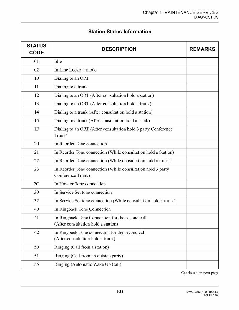
DIAGNOSTICS
Station Status Information
Continued on next page
STATUS CODE DESCRIPTION REMARKS
01 Idle
02 In Line Lockout mode
10 Dialing to an ORT
11 Dialing to a trunk
12 Dialing to an ORT (After consultation hold a station)
13 Dialing to an ORT (After consultation hold a trunk)
14 Dialing to a trunk (After consultation hold a station)
15 Dialing to a trunk (After consultation hold a trunk)
1F Dialing to an ORT (After consultation hold 3 party Conference Trunk)
20 In Reorder Tone connection
21 In Reorder Tone connection (While consultation hold a Station)
22 In Reorder Tone connection (While consultation hold a trunk)
23 In Reorder Tone connection (While consultation hold 3 party Conference Trunk)
2C In Howler Tone connection
30 In Service Set tone connection
32 In Service Set tone connection (While consultation hold a trunk)
40 In Ringback Tone Connection
41 In Ringback Tone Connection for the second call(After consultation hold a station)
42 In Ringback Tone connection for the second call (After consultation hold a trunk)
50 Ringing (Call from a station)
51 Ringing (Call from an outside party)
55 Ringing (Automatic Wake Up Call)
Chapter 1 MAINTENANCE SERVICES
1-23 NWA-033627-001 Rev.4.095ch1001.fm
DIAGNOSTICS
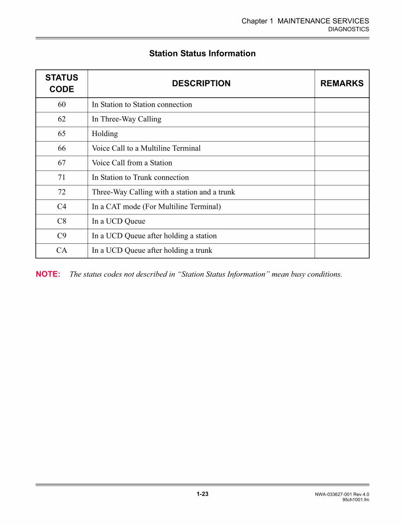
Station Status Information
NOTE: The status codes not described in “Station Status Information” mean busy conditions.
STATUS CODE DESCRIPTION REMARKS
60 In Station to Station connection
62 In Three-Way Calling
65 Holding
66 Voice Call to a Multiline Terminal
67 Voice Call from a Station
71 In Station to Trunk connection
72 Three-Way Calling with a station and a trunk
C4 In a CAT mode (For Multiline Terminal)
C8 In a UCD Queue
C9 In a UCD Queue after holding a station
CA In a UCD Queue after holding a trunk
Chapter 1 MAINTENANCE SERVICES
1-24 NWA-033627-001 Rev.4.095ch1001.fm
DIAGNOSTICS
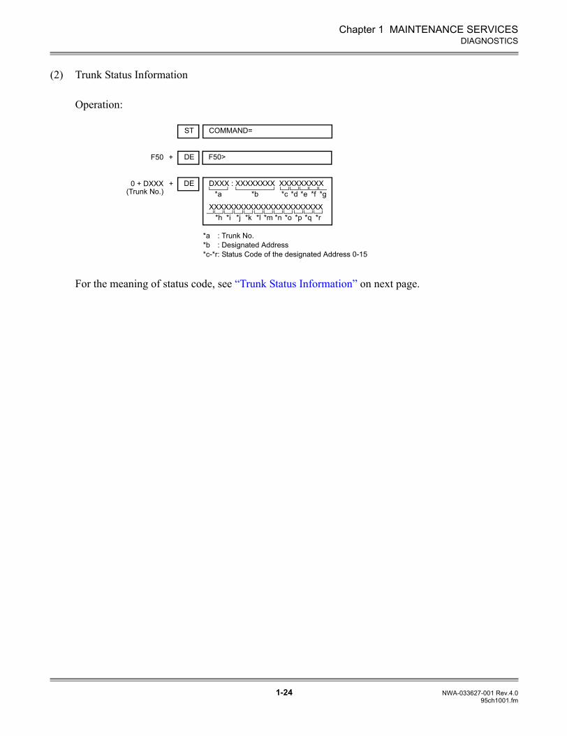
(2) Trunk Status Information
Operation:
For the meaning of status code, see “Trunk Status Information” on next page.
DE+ F50>F50
ST COMMAND=
DE+ DXXX : XXXXXXXX XXXXXXXXX0 + DXXX(Trunk No.) *a *b *c *d *e *f *g
XXXXXXXXXXXXXXXXXXXXXXX*h *i *j *k *l *m *n *o *p *q *r
*a : Trunk No.*b : Designated Address*c-*r: Status Code of the designated Address 0-15
Chapter 1 MAINTENANCE SERVICES
1-25 NWA-033627-001 Rev.4.095ch1001.fm
DIAGNOSTICS
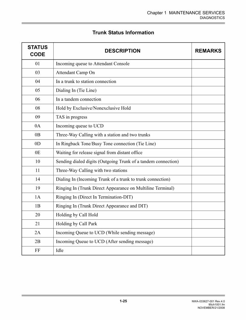
Trunk Status Information
STATUS CODE DESCRIPTION REMARKS
01 Incoming queue to Attendant Console
03 Attendant Camp On
04 In a trunk to station connection
05 Dialing In (Tie Line)
06 In a tandem connection
08 Hold by Exclusive/Nonexclusive Hold
09 TAS in progress
0A Incoming queue to UCD
0B Three-Way Calling with a station and two trunks
0D In Ringback Tone/Busy Tone connection (Tie Line)
0E Waiting for release signal from distant office
10 Sending dialed digits (Outgoing Trunk of a tandem connection)
11 Three-Way Calling with two stations
14 Dialing In (Incoming Trunk of a trunk to trunk connection)
19 Ringing In (Trunk Direct Appearance on Multiline Terminal)
1A Ringing In (Direct In Termination-DIT)
1B Ringing In (Trunk Direct Appearance and DIT)
20 Holding by Call Hold
21 Holding by Call Park
2A Incoming Queue to UCD (While sending message)
2B Incoming Queue to UCD (After sending message)
FF Idle
NOVEMBER/21/2008
Chapter 1 MAINTENANCE SERVICES
1-26 NWA-033627-001 Rev.4.095ch1001.fm
DIAGNOSTICS
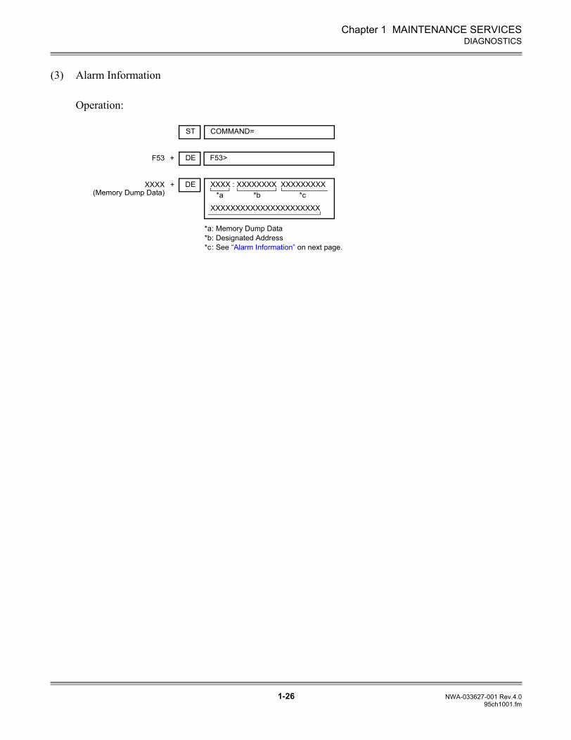
(3) Alarm Information
Operation:
DE+ F53>F53
ST COMMAND=
DE+ XXXX : XXXXXXXX XXXXXXXXXXXXX(Memory Dump Data) *a *b *c
XXXXXXXXXXXXXXXXXXXXXX
*a: Memory Dump Data*b: Designated Address*c: See “Alarm Information” on next page.
Chapter 1 MAINTENANCE SERVICES
1-27 NWA-033627-001 Rev.4.095ch1001.fm
DIAGNOSTICS
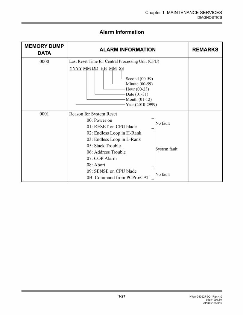
Alarm Information
MEMORY DUMP DATA ALARM INFORMATION REMARKS
0000 Last Reset Time for Central Processing Unit (CPU)
0001 Reason for System Reset00: Power on01: RESET on CPU blade02: Endless Loop in H-Rank03: Endless Loop in L-Rank05: Stack Trouble06: Address Trouble07: COP Alarm08: Abort09: SENSE on CPU blade0B: Command from PCPro/CAT
YYYY MM DD HH MM SS
Second (00-59)Minute (00-59)Hour (00-23)Date (01-31)Month (01-12)Year (2010-2999)
No fault
System fault
No fault
APRIL/16/2010
Chapter 1 MAINTENANCE SERVICES
1-28 NWA-033627-001 Rev.4.095ch1001.fm
BATTERY REPLACEMENT
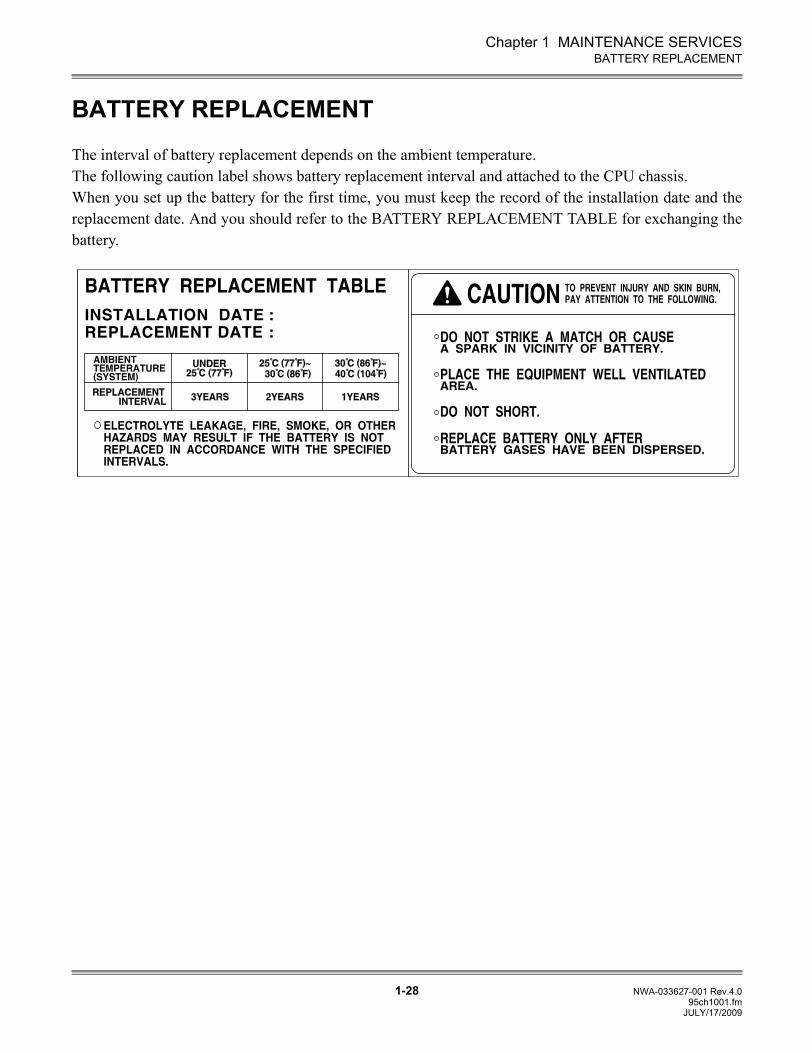
BATTERY REPLACEMENT
The interval of battery replacement depends on the ambient temperature.The following caution label shows battery replacement interval and attached to the CPU chassis.When you set up the battery for the first time, you must keep the record of the installation date and thereplacement date. And you should refer to the BATTERY REPLACEMENT TABLE for exchanging thebattery.
JULY/17/2009
Chapter 1 MAINTENANCE SERVICES
1-29 NWA-033627-001 Rev.4.095ch1001.fm
FAULT REPORT SCHEDULING
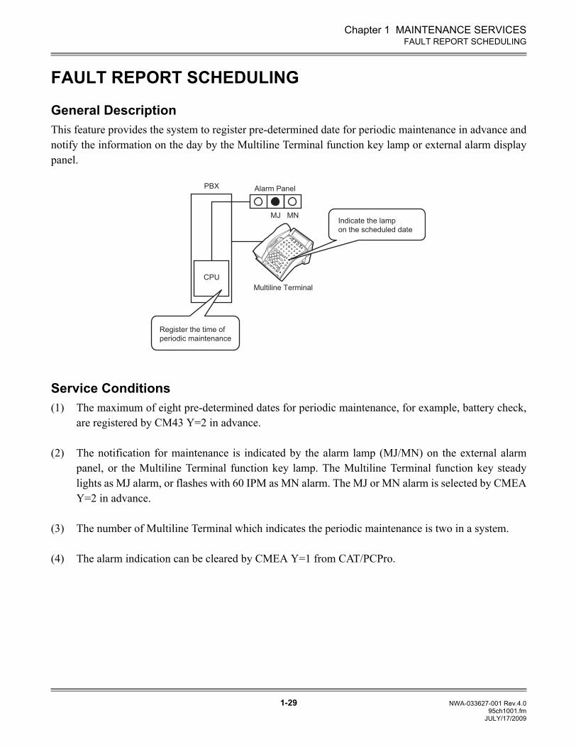
FAULT REPORT SCHEDULING
General DescriptionThis feature provides the system to register pre-determined date for periodic maintenance in advance andnotify the information on the day by the Multiline Terminal function key lamp or external alarm displaypanel.
Service Conditions (1) The maximum of eight pre-determined dates for periodic maintenance, for example, battery check,
are registered by CM43 Y=2 in advance.
(2) The notification for maintenance is indicated by the alarm lamp (MJ/MN) on the external alarmpanel, or the Multiline Terminal function key lamp. The Multiline Terminal function key steadylights as MJ alarm, or flashes with 60 IPM as MN alarm. The MJ or MN alarm is selected by CMEAY=2 in advance.
(3) The number of Multiline Terminal which indicates the periodic maintenance is two in a system.
(4) The alarm indication can be cleared by CMEA Y=1 from CAT/PCPro.
CPU
PBX Alarm Panel
MJ MN
Feature
Feature
4
5
6
GHIGHI
JKLJKL7
8
9
PQRS
PQRS
TUVTUV
0
#O
PER
OPER
1
2
3ABCABC
DEFDEF
Multiline Terminal
Register the time of
periodic maintenance
Indicate the lamp
on the scheduled date
JULY/17/2009
Chapter 1 MAINTENANCE SERVICES
1-30 NWA-033627-001 Rev.4.095ch1001.fm
FAULT REPORT SCHEDULING
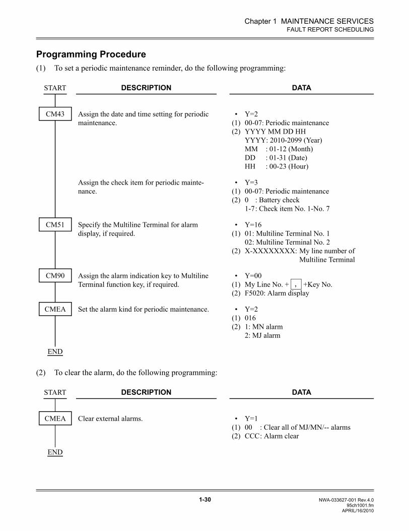
Programming Procedure(1) To set a periodic maintenance reminder, do the following programming:
(2) To clear the alarm, do the following programming:
DESCRIPTION DATA
Assign the date and time setting for periodic maintenance.
•(1)(2)
Y=200-07: Periodic maintenanceYYYY MM DD HHYYYY: 2010-2099 (Year)MM : 01-12 (Month)DD : 01-31 (Date)HH : 00-23 (Hour)
Assign the check item for periodic mainte-nance.
•(1)(2)
Y=300-07: Periodic maintenance0 : Battery check1-7: Check item No. 1-No. 7
Specify the Multiline Terminal for alarm display, if required.
• (1)
(2)
Y=1601: Multiline Terminal No. 102: Multiline Terminal No. 2X-XXXXXXXX: My line number of
Multiline Terminal
Assign the alarm indication key to Multiline Terminal function key, if required.
• (1) (2)
Y=00My Line No. + +Key No. F5020: Alarm display
Set the alarm kind for periodic maintenance. • (1) (2)
Y=20161: MN alarm2: MJ alarm
DESCRIPTION DATA
Clear external alarms. • (1) (2)
Y=100 : Clear all of MJ/MN/-- alarmsCCC: Alarm clear
START
CM43
CM51
CM90,
CMEA
END
START
CMEA
END
APRIL/16/2010
Chapter 1 MAINTENANCE SERVICES
1-31 NWA-033627-001 Rev.4.095ch1001.fm
FAULT REPORT SCHEDULING
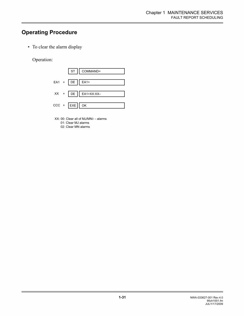
Operating Procedure
• To clear the alarm display
Operation:
DE+ EA1>EA1
ST COMMAND=
DE+ EA1>XX:XX–XX
XX: 00: Clear all of MJ/MN/- - alarms01: Clear MJ alarms02: Clear MN alarms
EXE+ OKCCC
JULY/17/2009
Chapter 1 MAINTENANCE SERVICES
1-32 NWA-033627-001 Rev.4.095ch1001.fm
VoIP LOG COLLECTION
VoIP LOG COLLECTION
General DescriptionBy collecting the fault logs or call logs and outputting them, you can know the causes when faults or erroroccur in the SV8300.
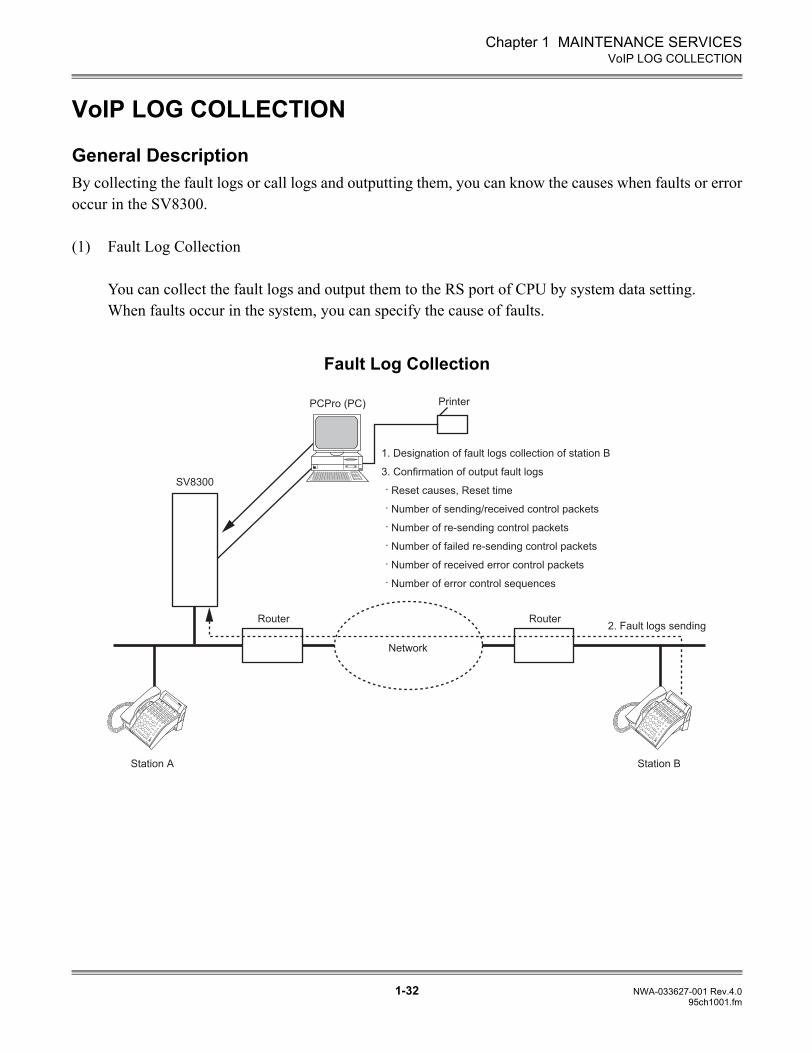
(1) Fault Log Collection
You can collect the fault logs and output them to the RS port of CPU by system data setting.When faults occur in the system, you can specify the cause of faults.
Fault Log Collection
1. Designation of fault logs collection of station B
3. Confirmation of output fault logs
. Reset causes, Reset time
. Number of sending/received control packets
. Number of re-sending control packets
. Number of failed re-sending control packets
. Number of received error control packets
. Number of error control sequences
2. Fault logs sending
Network
Router
Station A Station B
Router
SV8300
NEC
NEC
ExitExit
HelpHelp
MIC
MIC
NEC
NEC
ExitExit
HelpHelp
MIC
MIC
PCPro (PC) Printer
Chapter 1 MAINTENANCE SERVICES
1-33 NWA-033627-001 Rev.4.095ch1001.fm
VoIP LOG COLLECTION
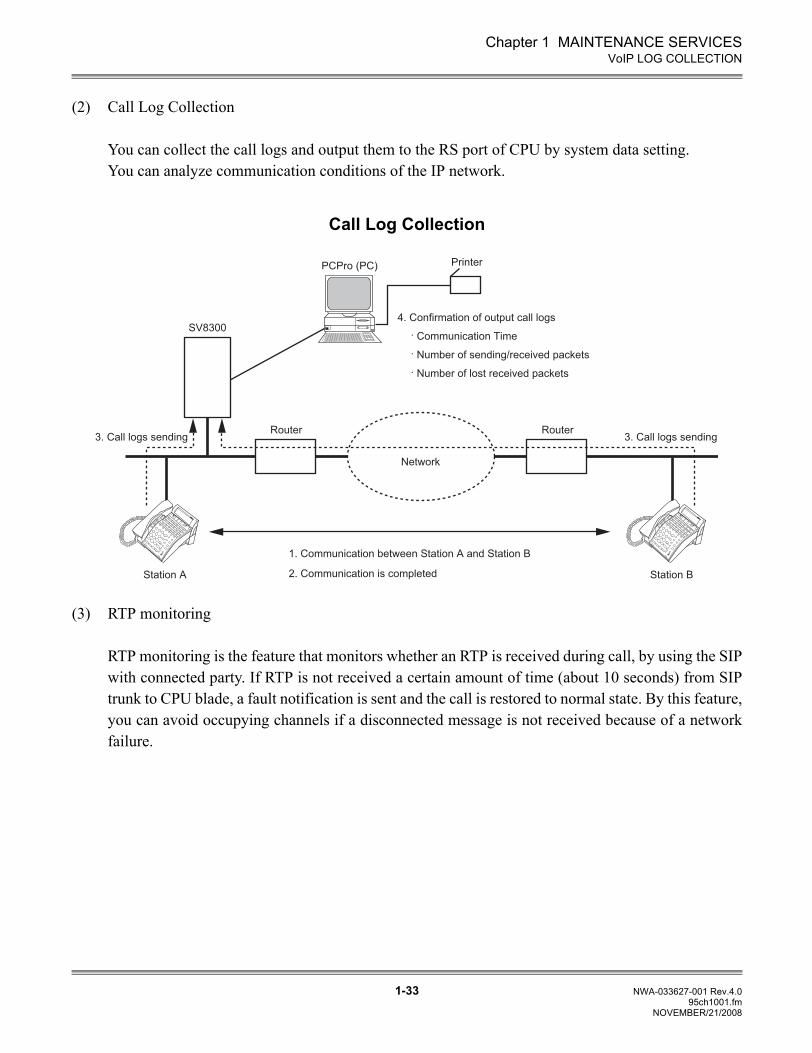
(2) Call Log Collection
You can collect the call logs and output them to the RS port of CPU by system data setting.You can analyze communication conditions of the IP network.
Call Log Collection
(3) RTP monitoring
RTP monitoring is the feature that monitors whether an RTP is received during call, by using the SIPwith connected party. If RTP is not received a certain amount of time (about 10 seconds) from SIPtrunk to CPU blade, a fault notification is sent and the call is restored to normal state. By this feature,you can avoid occupying channels if a disconnected message is not received because of a networkfailure.
4. Confirmation of output call logs
. Communication Time
. Number of sending/received packets
. Number of lost received packets
1. Communication between Station A and Station B
2. Communication is completed
3. Call logs sending3. Call logs sending
Network
Router
Station A Station B
Router
SV8300
PrinterPCPro (PC)
NEC
NEC
ExitExit
HelpHelp
MIC
MIC
NEC
NEC
ExitExit
HelpHelp
MIC
MIC
NOVEMBER/21/2008
Chapter 1 MAINTENANCE SERVICES
1-34 NWA-033627-001 Rev.4.095ch1001.fm
VoIP LOG COLLECTION
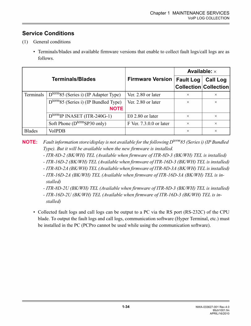
Service Conditions(1) General conditions
• Terminals/blades and available firmware versions that enable to collect fault logs/call logs are asfollows.
NOTE: Fault information store/display is not available for the following Dterm85 (Series i) (IP Bundled Type). But it will be available when the new firmware is installed.- ITR-8D-2 (BK/WH) TEL (Available when firmware of ITR-8D-3 (BK/WH) TEL is installed)- ITR-16D-2 (BK/WH) TEL (Available when firmware of ITR-16D-3 (BK/WH) TEL is installed)- ITR-8D-2A (BK/WH) TEL (Available when firmware of ITR-8D-3A (BK/WH) TEL is installed)- ITR-16D-2A (BK/WH) TEL (Available when firmware of ITR-16D-3A (BK/WH) TEL is in-
stalled)- ITR-8D-2U (BK/WH) TEL (Available when firmware of ITR-8D-3 (BK/WH) TEL is installed)- ITR-16D-2U (BK/WH) TEL (Available when firmware of ITR-16D-3 (BK/WH) TEL is in-
stalled)
• Collected fault logs and call logs can be output to a PC via the RS port (RS-232C) of the CPUblade. To output the fault logs and call logs, communication software (Hyper Terminal, etc.) mustbe installed in the PC (PCPro cannot be used while using the communication software).
Terminals/Blades Firmware VersionAvailable: ×
Fault LogCollection
Call LogCollection
Terminals Dterm85 (Series i) (IP Adapter Type) Ver. 2.80 or later × ×
Dterm85 (Series i) (IP Bundled Type)NOTE
Ver. 2.80 or later × ×
DtermIP INASET (ITR-240G-1) E0 2.80 or later × ×
Soft Phone (DtermSP30 only) F Ver. 7.3.0.0 or later × ×
Blades VoIPDB × ×
APRIL/16/2010
Chapter 1 MAINTENANCE SERVICES
1-35 NWA-033627-001 Rev.4.095ch1001.fm
VoIP LOG COLLECTION
NOTE: To use Hyper Terminal, select File Properties, and set emulation to VT100.
• To collect the fault logs and call logs, be sure to set the CPU blade to on-line mode (set SENSEswitch to 0-4).
(2) Conditions of fault log collection
• By collecting fault logs, you can specify the reset causes and reset time.• By collecting fault logs, you can calculate the number of sending control packets, the number of
re-sending control packets, the number of failed re-sending control packets, the number ofreceived control packets, the received error control packets, and the error number of controlsequences.
• The fault logs are collected by the following timing.- When IP Stations login to the system, and when the VoIPDB is in online status- When you set the system data for fault logs collection (CMEA Y=6>11) from PCPro/CAT
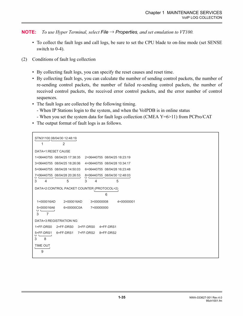
• The output format of fault logs is as follows.
STN31100 08/04/30 12:48:19
DATA=1:RESET CAUSE
1=06440755 08/04/25 17:38:35 2=06440755 08/04/25 18:23:19
3=06440755 08/04/25 18:26:06 4=06440755 08/04/28 10:34:17
5=06440755 08/04/28 14:50:03 6=06440755 08/04/28 16:23:48
7=06440755 08/04/28 20:26:53 8=06440755 08/04/30 12:48:03
DATA=2:CONTROL PACKET COUNTER (PROTOCOL=2)
1=000016AD 2=000016AD 3=00000008 4=00000001
5=000016A6 6=00000C0A 7=00000000
DATA=3:REGISTRATION NG
1=FF-DRS0 2=FF-DRS0 3=FF-DRS0 4=FF-DRS1
5=FF-DRS1 6=FF-DRS1 7=FF-DRS2 8=FF-DRS2
TIME OUT
1 2
3 34
3 7
3 8
9
5
6
4 5
Chapter 1 MAINTENANCE SERVICES
1-36 NWA-033627-001 Rev.4.095ch1001.fm
VoIP LOG COLLECTION
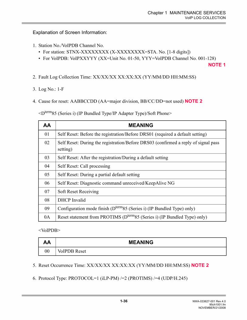
Explanation of Screen Information:
1. Station No./VoIPDB Channel No.• For station: STNX-XXXXXXXX (X-XXXXXXXX=STA. No. [1-8 digits])• For VoIPDB: VoIPXXYYY (XX=Unit No. 01-50, YYY=VoIPDB Channel No. 001-128)
NOTE 1
2. Fault Log Collection Time: XX/XX/XX XX:XX:XX (YY/MM/DD HH:MM:SS)
3. Log No.: 1-F
4. Cause for reset: AABBCCDD (AA=major division, BB/CC/DD=not used) NOTE 2
<Dterm85 (Series i) (IP Bundled Type/IP Adapter Type)/Soft Phone>
<VoIPDB>
5. Reset Occurrence Time: XX/XX/XX XX:XX:XX (YY/MM/DD HH:MM:SS) NOTE 2
6. Protocol Type: PROTOCOL=1 (iLP-PM) /=2 (PROTIMS) /=4 (UDP/H.245)
AA MEANING01 Self Reset: Before the registration/Before DRS01 (required a default setting)
02 Self Reset: During the registration/Before DRS03 (confirmed a reply of signal pass setting)
03 Self Reset: After the registration/During a default setting
04 Self Reset: Call processing
05 Self Reset: During a partial default setting
06 Self Reset: Diagnostic command unreceived/KeepAlive NG
07 Soft Reset Receiving
08 DHCP Invalid
09 Configuration mode finish (Dterm85 (Series i) (IP Bundled Type) only)
0A Reset statement from PROTIMS (Dterm85 (Series i) (IP Bundled Type) only)
AA MEANING00 VoIPDB Reset
NOVEMBER/21/2008
Chapter 1 MAINTENANCE SERVICES
1-37 NWA-033627-001 Rev.4.095ch1001.fm
VoIP LOG COLLECTION
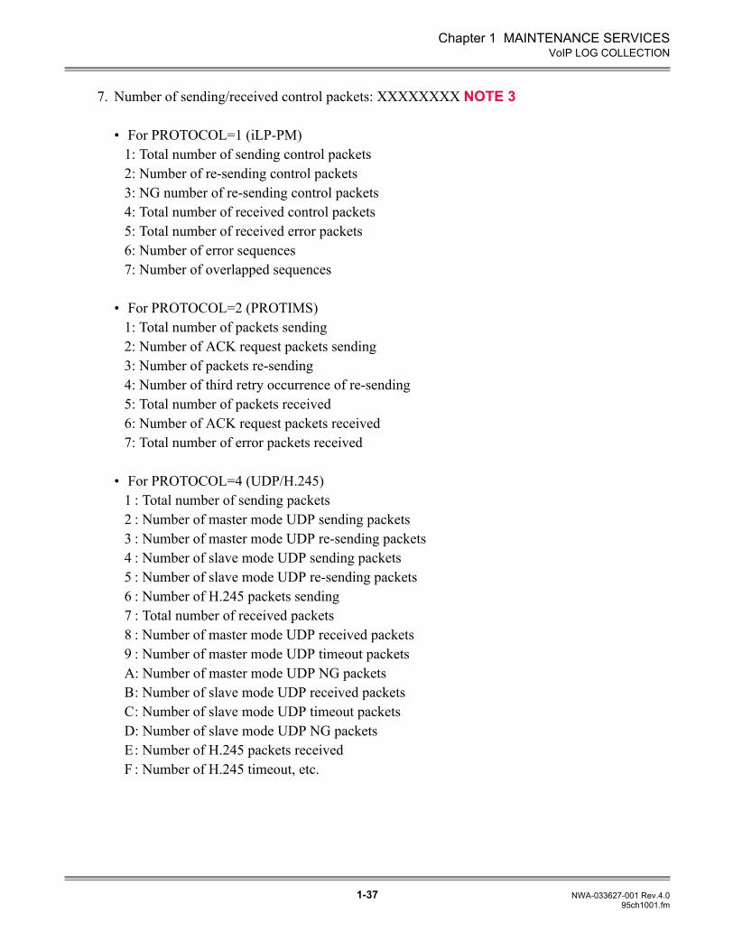
7. Number of sending/received control packets: XXXXXXXX NOTE 3
• For PROTOCOL=1 (iLP-PM)1: Total number of sending control packets2: Number of re-sending control packets3: NG number of re-sending control packets4: Total number of received control packets5: Total number of received error packets6: Number of error sequences7: Number of overlapped sequences
• For PROTOCOL=2 (PROTIMS)1: Total number of packets sending2: Number of ACK request packets sending3: Number of packets re-sending4: Number of third retry occurrence of re-sending5: Total number of packets received6: Number of ACK request packets received7: Total number of error packets received
• For PROTOCOL=4 (UDP/H.245)1 : Total number of sending packets2 : Number of master mode UDP sending packets3 : Number of master mode UDP re-sending packets4 : Number of slave mode UDP sending packets 5 : Number of slave mode UDP re-sending packets 6 : Number of H.245 packets sending7 : Total number of received packets8 : Number of master mode UDP received packets 9 : Number of master mode UDP timeout packets A: Number of master mode UDP NG packetsB: Number of slave mode UDP received packetsC: Number of slave mode UDP timeout packetsD: Number of slave mode UDP NG packetsE: Number of H.245 packets receivedF : Number of H.245 timeout, etc.
Chapter 1 MAINTENANCE SERVICES
1-38 NWA-033627-001 Rev.4.095ch1001.fm
VoIP LOG COLLECTION
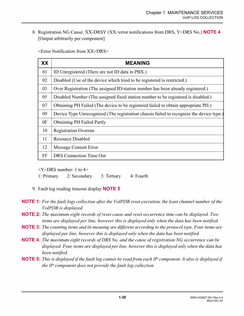
8. Registration NG Cause: XX-DRSY (XX=error notifications from DRS, Y=DRS No.) NOTE 4[Output arbitrarily per component]
<Error Notification from XX=DRS>
<Y=DRS number: 1 to 4>1: Primary 2: Secondary 3: Tertiary 4: Fourth
9. Fault log reading timeout display NOTE 5
NOTE 1: For the fault logs collection after the VoIPDB reset execution, the least channel number of the VoIPDB is displayed.
NOTE 2: The maximum eight records of reset cause and reset occurrence time can be displayed. Two items are displayed per line, however this is displayed only when the data has been notified.
NOTE 3: The counting items and its meaning are different according to the protocol type. Four items are displayed per line, however this is displayed only when the data has been notified.
NOTE 4: The maximum eight records of DRS No. and the cause of registration NG occurrence can be displayed. Four items are displayed per line, however this is displayed only when the data has been notified.
NOTE 5: This is displayed if the fault log cannot be read from each IP component. It also is displayed if the IP component does not provide the fault log collection.
XX MEANING01 ID Unregistered (There are not ID data in PBX.)
02 Disabled (Use of the device which tried to be registered is restricted.)
03 Over Registration (The assigned ID/station number has been already registered.)
05 Disabled Number (The assigned fixed station number to be registered is disabled.)
07 Obtaining PH Failed (The device to be registered failed to obtain appropriate PH.)
09 Device Type Unrecognized (The registration chassis failed to recognize the device type.)
0F Obtaining PH Failed Partly
10 Registration Overrun
11 Resource Disabled
12 Message Content Error
FF DRS Connection Time Out
Chapter 1 MAINTENANCE SERVICES
1-39 NWA-033627-001 Rev.4.095ch1001.fm
VoIP LOG COLLECTION
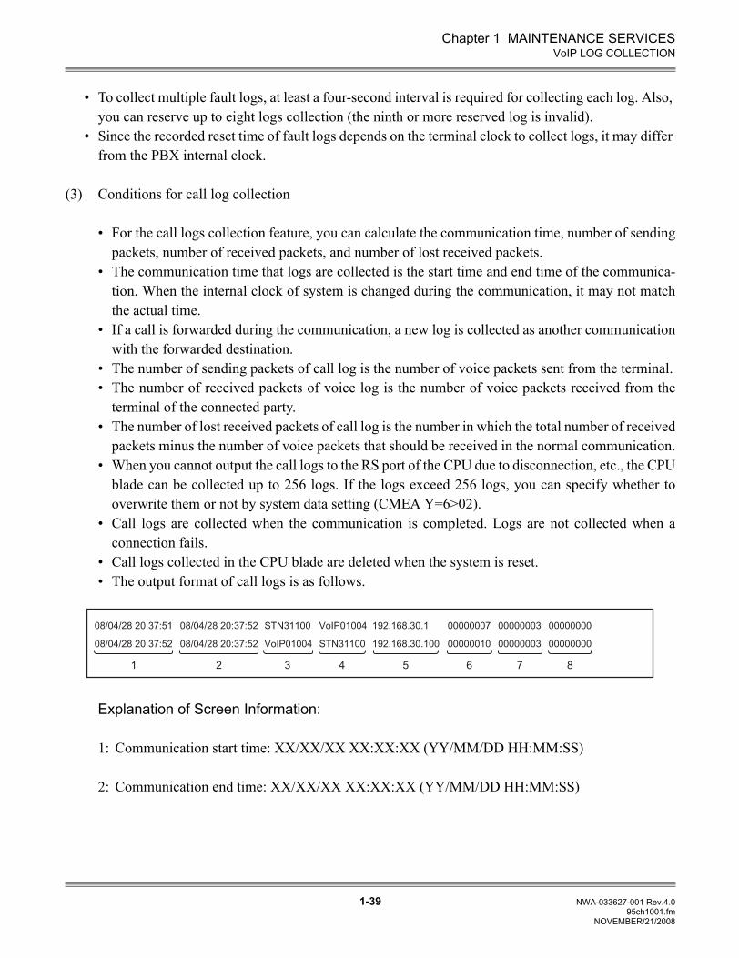
• To collect multiple fault logs, at least a four-second interval is required for collecting each log. Also, you can reserve up to eight logs collection (the ninth or more reserved log is invalid).
• Since the recorded reset time of fault logs depends on the terminal clock to collect logs, it may differ from the PBX internal clock.
(3) Conditions for call log collection
• For the call logs collection feature, you can calculate the communication time, number of sendingpackets, number of received packets, and number of lost received packets.
• The communication time that logs are collected is the start time and end time of the communica-tion. When the internal clock of system is changed during the communication, it may not matchthe actual time.
• If a call is forwarded during the communication, a new log is collected as another communicationwith the forwarded destination.
• The number of sending packets of call log is the number of voice packets sent from the terminal.• The number of received packets of voice log is the number of voice packets received from the
terminal of the connected party.• The number of lost received packets of call log is the number in which the total number of received
packets minus the number of voice packets that should be received in the normal communication.• When you cannot output the call logs to the RS port of the CPU due to disconnection, etc., the CPU
blade can be collected up to 256 logs. If the logs exceed 256 logs, you can specify whether tooverwrite them or not by system data setting (CMEA Y=6>02).
• Call logs are collected when the communication is completed. Logs are not collected when aconnection fails.
• Call logs collected in the CPU blade are deleted when the system is reset.• The output format of call logs is as follows.
Explanation of Screen Information:
1: Communication start time: XX/XX/XX XX:XX:XX (YY/MM/DD HH:MM:SS)
2: Communication end time: XX/XX/XX XX:XX:XX (YY/MM/DD HH:MM:SS)
08/04/28 20:37:51 08/04/28 20:37:52 STN31100 VoIP01004 192.168.30.1 00000007 00000003 00000000
08/04/28 20:37:52 08/04/28 20:37:52 VoIP01004 STN31100 192.168.30.100 00000010 00000003 00000000
1 2 3 4 5 7 86
NOVEMBER/21/2008
Chapter 1 MAINTENANCE SERVICES
1-40 NWA-033627-001 Rev.4.095ch1001.fm
VoIP LOG COLLECTION
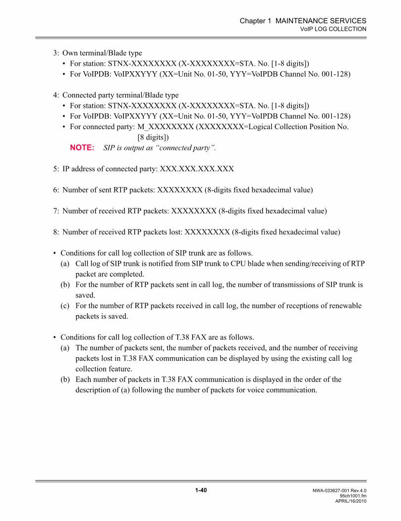
3: Own terminal/Blade type• For station: STNX-XXXXXXXX (X-XXXXXXXX=STA. No. [1-8 digits])• For VoIPDB: VoIPXXYYY (XX=Unit No. 01-50, YYY=VoIPDB Channel No. 001-128)
4: Connected party terminal/Blade type• For station: STNX-XXXXXXXX (X-XXXXXXXX=STA. No. [1-8 digits])• For VoIPDB: VoIPXXYYY (XX=Unit No. 01-50, YYY=VoIPDB Channel No. 001-128)• For connected party: M_XXXXXXXX (XXXXXXXX=Logical Collection Position No.
[8 digits])NOTE: SIP is output as “connected party”.
5: IP address of connected party: XXX.XXX.XXX.XXX
6: Number of sent RTP packets: XXXXXXXX (8-digits fixed hexadecimal value)
7: Number of received RTP packets: XXXXXXXX (8-digits fixed hexadecimal value)
8: Number of received RTP packets lost: XXXXXXXX (8-digits fixed hexadecimal value)
• Conditions for call log collection of SIP trunk are as follows.(a) Call log of SIP trunk is notified from SIP trunk to CPU blade when sending/receiving of RTP
packet are completed.(b) For the number of RTP packets sent in call log, the number of transmissions of SIP trunk is
saved.(c) For the number of RTP packets received in call log, the number of receptions of renewable
packets is saved.
• Conditions for call log collection of T.38 FAX are as follows.(a) The number of packets sent, the number of packets received, and the number of receiving
packets lost in T.38 FAX communication can be displayed by using the existing call log collection feature.
(b) Each number of packets in T.38 FAX communication is displayed in the order of the description of (a) following the number of packets for voice communication.
APRIL/16/2010
Chapter 1 MAINTENANCE SERVICES
1-41 NWA-033627-001 Rev.4.095ch1001.fm
VoIP LOG COLLECTION
(4) Conditions for RTP monitoring
• If the SIP trunk does not receive RTP for 10 seconds after establishing the path, the faultinformation (fault kind 043) is registered and the path is released.
• The fault information (fault kind 043) is registered whenever the path is released by RTP monitor-ing.
• The RTP monitoring starts when one packet is received from the originating office after a path isestablished. Even during ringing, RTP monitoring functions when sending/receiving RTP.
• When the path is released by RTP monitoring, the SIP call disconnect message is sent to theoriginating office.
APRIL/16/2010
Chapter 1 MAINTENANCE SERVICES
1-42 NWA-033627-001 Rev.4.095ch1001.fm
VoIP LOG COLLECTION
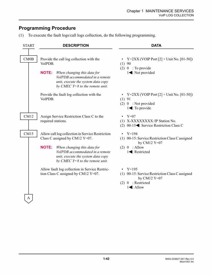
Programming Procedure(1) To execute the fault logs/call logs collection, do the following programming.
DESCRIPTION DATA
Provide the call log collection with the VoIPDB.
NOTE: When changing this data for VoIPDB accommodated in a remote unit, execute the system data copy by CMEC Y=8 to the remote unit.
•(1)(2)
Y=2XX (VOIP Port [2] + Unit No. [01-50])900 : To provide1 : Not provided
Provide the fault log collection with the VoIPDB.
•(1)(2)
Y=2XX (VOIP Port [2] + Unit No. [01-50])910 : Not provided1 : To provide
Assign Service Restriction Class C to the required stations.
•(1)(2)
Y=07X-XXXXXXXX:IP Station No.00-15 : Service Restriction Class C
Allow call log collection in Service Restriction Class C assigned by CM12 Y=07.
NOTE: When changing this data for VoIPDB accommodated in a remote unit, execute the system data copy by CMEC Y=8 to the remote unit.
•(1)
(2)
Y=19400-15: Service Restriction Class C assigned
by CM12 Y=070 : Allow1 : Restricted
Allow fault log collection in Service Restric-tion Class C assigned by CM12 Y=07.
•(1)
(2)
Y=19500-15: Service Restriction Class C assigned
by CM12 Y=070 : Restricted1 : Allow
START
CM0B
CM12
CM15
A
Chapter 1 MAINTENANCE SERVICES
1-43 NWA-033627-001 Rev.4.095ch1001.fm
VoIP LOG COLLECTION
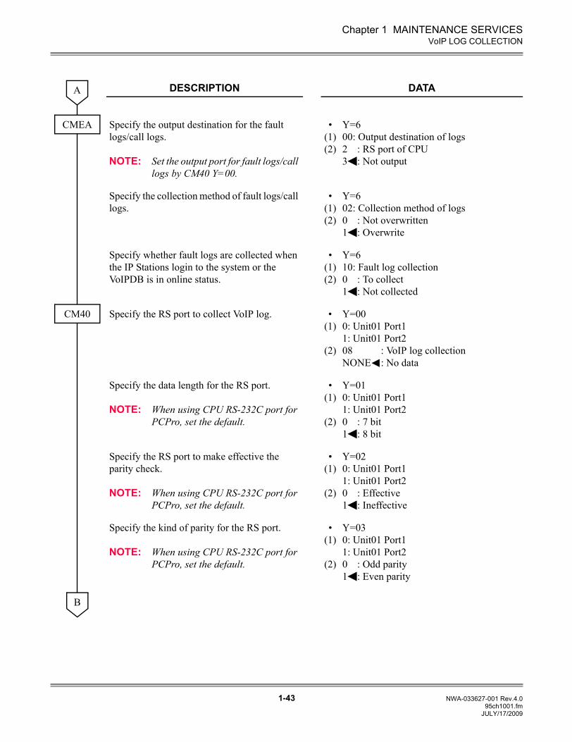
DESCRIPTION DATA
Specify the output destination for the fault logs/call logs.
NOTE: Set the output port for fault logs/call logs by CM40 Y=00.
•(1)(2)
Y=600: Output destination of logs2 : RS port of CPU3 : Not output
Specify the collection method of fault logs/call logs.
•(1)(2)
Y=602: Collection method of logs0 : Not overwritten1 : Overwrite
Specify whether fault logs are collected when the IP Stations login to the system or the VoIPDB is in online status.
•(1)(2)
Y=610: Fault log collection0 : To collect1 : Not collected
Specify the RS port to collect VoIP log. •(1)
(2)
Y=000: Unit01 Port11: Unit01 Port208 : VoIP log collectionNONE : No data
Specify the data length for the RS port.
NOTE: When using CPU RS-232C port for PCPro, set the default.
•(1)
(2)
Y=010: Unit01 Port11: Unit01 Port20 : 7 bit1 : 8 bit
Specify the RS port to make effective the parity check.
NOTE: When using CPU RS-232C port for PCPro, set the default.
•(1)
(2)
Y=020: Unit01 Port11: Unit01 Port20 : Effective1 : Ineffective
Specify the kind of parity for the RS port.
NOTE: When using CPU RS-232C port for PCPro, set the default.
•(1)
(2)
Y=030: Unit01 Port11: Unit01 Port20 : Odd parity1 : Even parity
A
CMEA
CM40
B
JULY/17/2009
Chapter 1 MAINTENANCE SERVICES
1-44 NWA-033627-001 Rev.4.095ch1001.fm
VoIP LOG COLLECTION
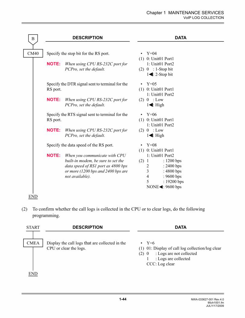
(2) To confirm whether the call logs is collected in the CPU or to clear logs, do the following programming.
DESCRIPTION DATA
Specify the stop bit for the RS port.
NOTE: When using CPU RS-232C port for PCPro, set the default.
•(1)
(2)
Y=040: Unit01 Port11: Unit01 Port20 : 1-Stop bit1 : 2-Stop bit
Specify the DTR signal sent to terminal for the RS port.
NOTE: When using CPU RS-232C port for PCPro, set the default.
•(1)
(2)
Y=050: Unit01 Port11: Unit01 Port20 : Low1 : High
Specify the RTS signal sent to terminal for the RS port.
NOTE: When using CPU RS-232C port for PCPro, set the default.
•(1)
(2)
Y=060: Unit01 Port11: Unit01 Port20 : Low1 : High
Specify the data speed of the RS port.
NOTE: When you communicate with CPU built-in modem, be sure to set the data speed of RS1 port as 4800 bps or more (1200 bps and 2400 bps are not available).
•(1)
(2)
Y=080: Unit01 Port11: Unit01 Port21 : 1200 bps2 : 2400 bps3 : 4800 bps4 : 9600 bps5 : 19200 bpsNONE : 9600 bps
DESCRIPTION DATA
Display the call logs that are collected in the CPU or clear the logs.
•(1)(2)
Y=601: Display of call log collection/log clear0 : Logs are not collected1 : Logs are collectedCCC: Log clear
B
CM40
END
START
CMEA
END
JULY/17/2009
Chapter 1 MAINTENANCE SERVICES
1-45 NWA-033627-001 Rev.4.095ch1001.fm
VoIP LOG COLLECTION
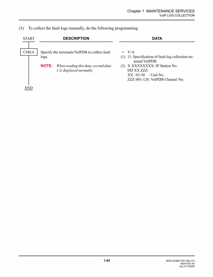
(3) To collect the fault logs manually, do the following programming.
DESCRIPTION DATA
Specify the terminals/VoIPDB to collect fault logs.
NOTE: When reading this data, second data 1 is displayed normally.
•(1)
(2)
Y=611: Specification of fault log collection ter-
minal/VoIPDBX-XXXXXXXX: IP Station No.DD XX ZZZ:XX :01-50 : Unit No.ZZZ:001-128: VoIPDB Channel No.
START
CMEA
END
JULY/17/2009
Chapter 1 MAINTENANCE SERVICES
1-46 NWA-033627-001 Rev.4.095ch1001.fm
QoS DISPLAY ON IP MULTILINE TERMINAL
QoS DISPLAY ON IP MULTILINE TERMINAL
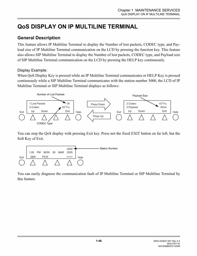
General DescriptionThis feature allows IP Multiline Terminal to display the Number of lost packets, CODEC type, and Pay-load size of IP Multiline Terminal communication on the LCD by pressing the function key. This featurealso allows SIP Multiline Terminal to display the Number of lost packets, CODEC type, and Payload sizeof SIP Multiline Terminal communication on the LCD by pressing the HELP key continuously.
Display Example:When QoS Display Key is pressed while an IP Multiline Terminal communicates or HELP Key is pressedcontinuously while a SIP Multiline Terminal communicates with the station number 3000, the LCD of IPMultiline Terminal or SIP Multiline Terminal displays as follows:
You can stop the QoS display with pressing Exit key. Press not the fixed EXIT button on far left, but theSoft Key of Exit.
You can easily diagnose the communication fault of IP Multiline Terminal or SIP Multiline Terminal bythis feature.
1.Lost Packet:
2.Codec:
UpExit Help
2.Codec:
3.Payload
Exit Help
Press Down
Press Up
ExitDown
34
G711u
G711u
40ms
Up ExitDown
Number of Lost Packets
CODEC Type
Payload Size
Help
3000
S&R >>>>PICK
1:26 PM MON 28 MAR 2005
Exit
Station Number
NOVEMBER/21/2008
Chapter 1 MAINTENANCE SERVICES
1-47 NWA-033627-001 Rev.4.095ch1001.fm
QoS DISPLAY ON IP MULTILINE TERMINAL
Service Conditions(1) Number of lost packets, CODEC type, and Payload size are displayed with pressing the Function key
that has been set during a communication.
(2) The displayed QoS information on the LCD is updated every 5 seconds.
(3) All information sent from the PBX is not displayed while the QoS information is displayed on theLCD.
(4) To stop the display of QoS information, press Soft key of Exit. If you do not that, the QoSinformation will keep being displayed.
(5) This feature is available for the IP Multiline Terminal version 2.81 or later.
(6) When using this feature for SIP Multiline Terminal, the data assignment of the QoS Display key(second data of CM90 Y=00 is set to “F1058”) is not necessary. QoS information is displayed withpressing the HELP key continuously.
Programming Procedure
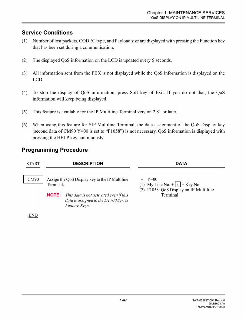
DESCRIPTION DATA
Assign the QoS Display key to the IP Multiline Terminal.
NOTE: This data is not activated even if this data is assigned to the DT700 Series Feature Keys.
•(1)(2)
Y=00My Line No. + + Key No.F1058: QoS Display on IP Multiline
Terminal
START
CM90,
END
NOVEMBER/21/2008
Chapter 1 MAINTENANCE SERVICES
1-48 NWA-033627-001 Rev.4.095ch1001.fm
STATION SERVICE STATUS DISPLAY
STATION SERVICE STATUS DISPLAY
General DescriptionThis feature enables to readout the setting status of the service for each station.
Service Conditions(1) The services whose setting status can be readout by this feature are the features that are set to single
line telephone, Multiline Terminal, PS, virtual station and built-in modem. The features that are setto DESKCON and ISDN telephone are not supported.
(2) Station numbers entered by the setting status readout command (CME4 Y=00, 01) are the stationnumber set to single line telephone, Multiline Terminal, virtual station, virtual station for PS, andbuilt-in modem. The station numbers for ISDN telephone cannot be entered ([DATA ERROR] isdisplayed if entered).
(3) The terminal connection status and the line status cannot be readout in offline. For the other features,the status can be readout regardless of online or offline.
(4) For the line status, when Sub Line is accommodated to Multiline Terminal and My Line number isinput to the first data, the status “Line is busy (1)” is displayed when incoming/outgoing calls to MyLine, and the status “Line is idle (0)” is displayed when incoming/outgoing calls to Sub Line.
(5) For Day/Night mode change, Day mode (D)/Night mode (N)/Mode A (A)/Mode B (B) are displayedeven if two kinds of modes (Day mode/Night mode) are set by CM65 Y=29.
NOVEMBER/21/2008
Chapter 1 MAINTENANCE SERVICES
1-49 NWA-033627-001 Rev.4.095ch1001.fm
STATION SERVICE STATUS DISPLAY
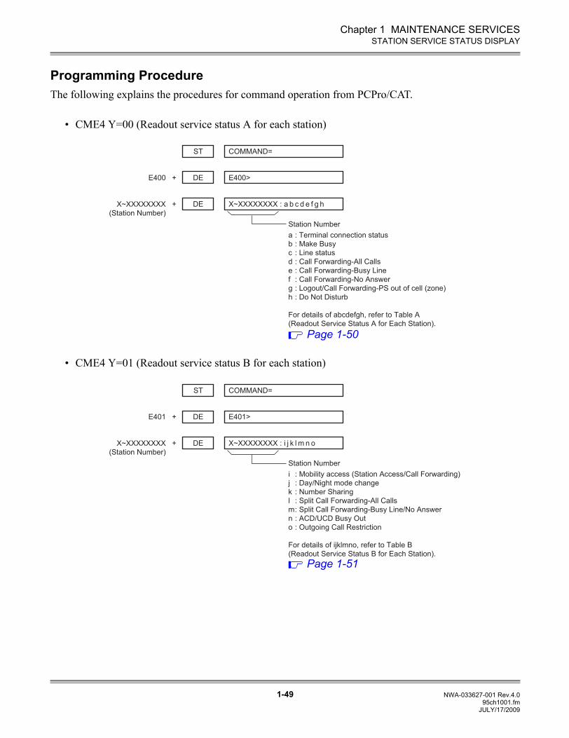
Programming ProcedureThe following explains the procedures for command operation from PCPro/CAT.
• CME4 Y=00 (Readout service status A for each station)
• CME4 Y=01 (Readout service status B for each station)
ST COMMAND=
+
DE+ E400>E400
DE X~XXXXXXXX : a b c d e f g hX~XXXXXXXX
(Station Number)
a : Terminal connection status
b : Make Busy
c : Line status
d : Call Forwarding-All Calls
e : Call Forwarding-Busy Line
f : Call Forwarding-No Answer
g : Logout/Call Forwarding-PS out of cell (zone)
h : Do Not Disturb
For details of abcdefgh, refer to Table A
(Readout Service Status A for Each Station).
Station Number
Page 1-50
ST COMMAND=
+
DE+ E401>E401
DE X~XXXXXXXX : i j k l m n oX~XXXXXXXX
(Station Number)
i : Mobility access (Station Access/Call Forwarding)
j : Day/Night mode change
k : Number Sharing
l : Split Call Forwarding-All Calls
m : Split Call Forwarding-Busy Line/No Answer
n : ACD/UCD Busy Out
o : Outgoing Call Restriction
For details of ijklmno, refer to Table B
(Readout Service Status B for Each Station).
Station Number
Page 1-51
JULY/17/2009
Chapter 1 MAINTENANCE SERVICES
1-50 NWA-033627-001 Rev.4.095ch1001.fm
STATION SERVICE STATUS DISPLAY
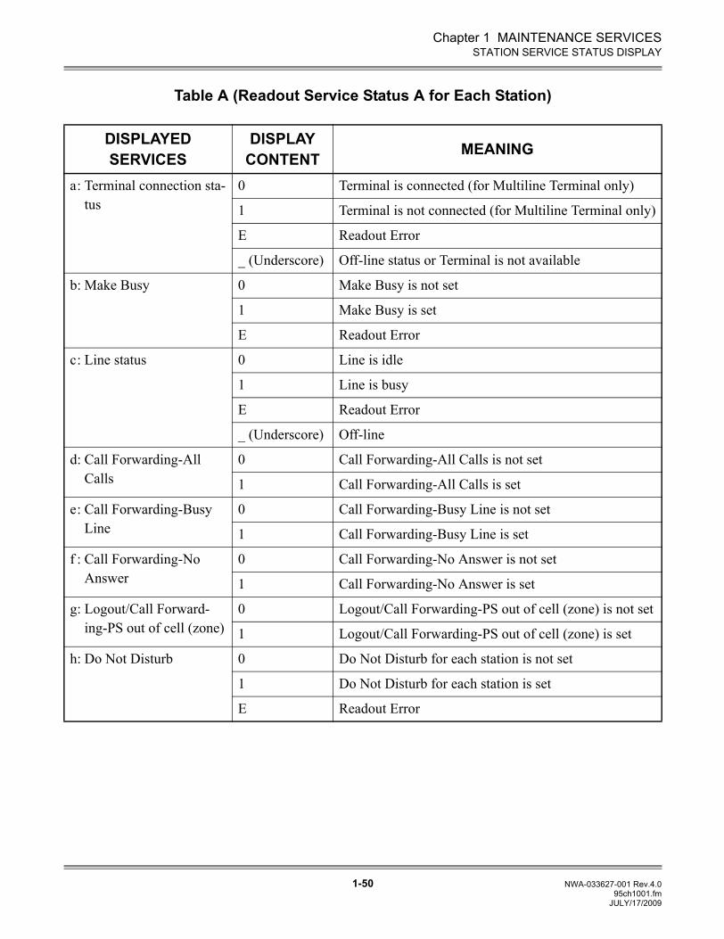
Table A (Readout Service Status A for Each Station)
DISPLAYED SERVICES
DISPLAY CONTENT MEANING
a: Terminal connection sta-tus
0 Terminal is connected (for Multiline Terminal only)
1 Terminal is not connected (for Multiline Terminal only)
E Readout Error
_ (Underscore) Off-line status or Terminal is not available
b: Make Busy 0 Make Busy is not set
1 Make Busy is set
E Readout Error
c: Line status 0 Line is idle
1 Line is busy
E Readout Error
_ (Underscore) Off-line
d: Call Forwarding-All Calls
0 Call Forwarding-All Calls is not set
1 Call Forwarding-All Calls is set
e: Call Forwarding-Busy Line
0 Call Forwarding-Busy Line is not set
1 Call Forwarding-Busy Line is set
f : Call Forwarding-No Answer
0 Call Forwarding-No Answer is not set
1 Call Forwarding-No Answer is set
g: Logout/Call Forward-ing-PS out of cell (zone)
0 Logout/Call Forwarding-PS out of cell (zone) is not set
1 Logout/Call Forwarding-PS out of cell (zone) is set
h: Do Not Disturb 0 Do Not Disturb for each station is not set
1 Do Not Disturb for each station is set
E Readout Error
JULY/17/2009
Chapter 1 MAINTENANCE SERVICES
1-51 NWA-033627-001 Rev.4.095ch1001.fm
STATION SERVICE STATUS DISPLAY
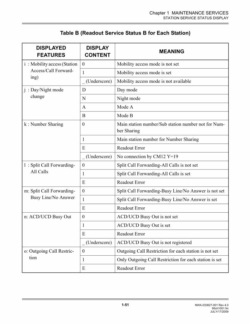
Table B (Readout Service Status B for Each Station)
DISPLAYED FEATURES
DISPLAY CONTENT MEANING
i : Mobility access (Station Access/Call Forward-ing)
0 Mobility access mode is not set
1 Mobility access mode is set
_ (Underscore) Mobility access mode is not available
j : Day/Night mode change
D Day mode
N Night mode
A Mode A
B Mode B
k : Number Sharing 0 Main station number/Sub station number not for Num-ber Sharing
1 Main station number for Number Sharing
E Readout Error
_ (Underscore) No connection by CM12 Y=19
l : Split Call Forwarding-All Calls
0 Split Call Forwarding-All Calls is not set
1 Split Call Forwarding-All Calls is set
E Readout Error
m: Split Call Forwarding-Busy Line/No Answer
0 Split Call Forwarding-Busy Line/No Answer is not set
1 Split Call Forwarding-Busy Line/No Answer is set
E Readout Error
n: ACD/UCD Busy Out 0 ACD/UCD Busy Out is not set
1 ACD/UCD Busy Out is set
E Readout Error
_ (Underscore) ACD/UCD Busy Out is not registered
o: Outgoing Call Restric-tion
0 Outgoing Call Restriction for each station is not set
1 Only Outgoing Call Restriction for each station is set
E Readout Error
JULY/17/2009
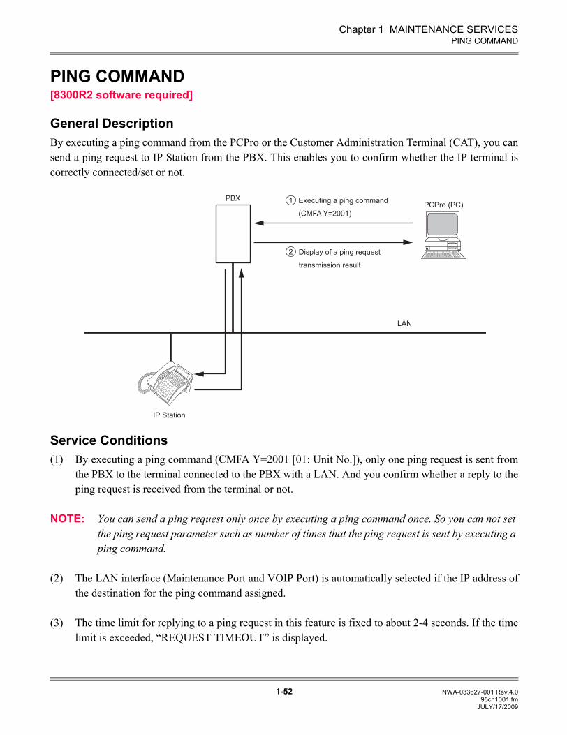
Chapter 1 MAINTENANCE SERVICES
1-52 NWA-033627-001 Rev.4.095ch1001.fm
PING COMMAND
PING COMMAND[8300R2 software required]
General DescriptionBy executing a ping command from the PCPro or the Customer Administration Terminal (CAT), you cansend a ping request to IP Station from the PBX. This enables you to confirm whether the IP terminal iscorrectly connected/set or not.
Service Conditions(1) By executing a ping command (CMFA Y=2001 [01: Unit No.]), only one ping request is sent from
the PBX to the terminal connected to the PBX with a LAN. And you confirm whether a reply to theping request is received from the terminal or not.
NOTE: You can send a ping request only once by executing a ping command once. So you can not set the ping request parameter such as number of times that the ping request is sent by executing a ping command.
(2) The LAN interface (Maintenance Port and VOIP Port) is automatically selected if the IP address ofthe destination for the ping command assigned.
(3) The time limit for replying to a ping request in this feature is fixed to about 2-4 seconds. If the timelimit is exceeded, “REQUEST TIMEOUT” is displayed.
PBX Executing a ping command
(CMFA Y=2001)
Display of a ping request
transmission result
PCPro (PC)
LAN
IP Station
NEC
NEC
ExitExit
HelpHelp
MIC
MIC
1
2
JULY/17/2009
Chapter 1 MAINTENANCE SERVICES
1-53 NWA-033627-001 Rev.4.095ch1001.fm
PING COMMAND
(4) You can not execute the ping command from multiple PCPro/CAT terminals at once. If you do that,“WAIT, BUSY NOW” is displayed.
(5) Even if a LAN port on the CPU blade is being used for PCPro/OAI or any other terminals, you canexecute the ping command.
(6) The following key operations are effective when the reply message resulting by executing the pingcommand is displayed.
• DE (space key): To send again a ping request to the same IP address as the last one.• - (hyphen key) : To send a ping request to the IP address with 1 subtracted from the last one.
Example: The ping request is sent to “192.168.1.2” if you press DE (space key) after sending itto “192.168.1.3”.
• S (return key) : To send a ping request to the IP address with 1 added to the last one.Example: The ping request is sent to “192.168.1.3” if you press S (return key) after sending it to
“192.168.1.2”.
NOTE: A LAN port on the CPU blade becomes occupied if you execute a ping command while DE (space key) is pressed.
(7) When LAN feature is not available due to a system data is not assigned or other reason,“HARDWARE ERROR” is displayed.
(8) The reply message resulting by executing the ping command is directly displayed in ICMP TYPE.And “OK”/ “ERROR” displayed in PCPro is not displayed. The reply message is as follows.
Example 1 <The reply message resulting by executing the ping command>: COMMAND=FA2001FA2001>192.168.1.2192.168.1.2: 0 ping OK (ICMP TYPE=0 Reply)
Example 2 <The reply message resulting by executing the ping command>: COMMAND=FA2001FA2001>192.168.1.2192.168.1.2: 3 ping NG (ICMP TYPE=3 Host unreachable)
JULY/17/2009
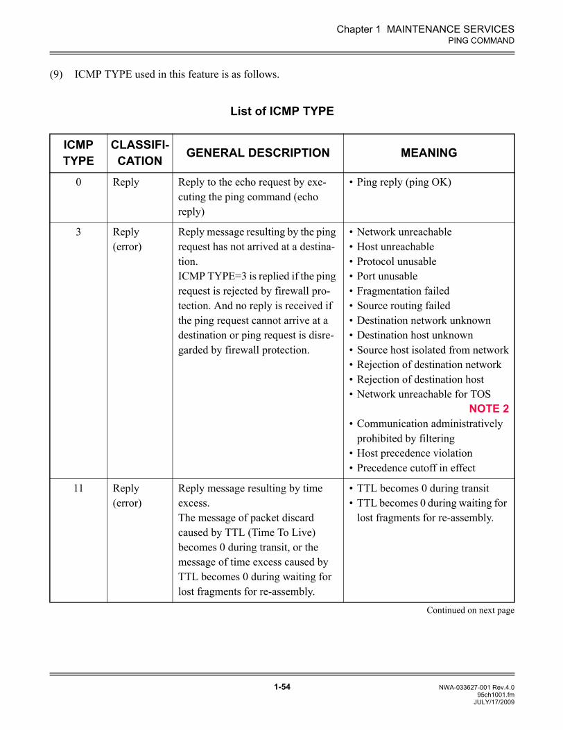
Chapter 1 MAINTENANCE SERVICES
1-54 NWA-033627-001 Rev.4.095ch1001.fm
PING COMMAND
(9) ICMP TYPE used in this feature is as follows.
List of ICMP TYPE
ICMP TYPE
CLASSIFI-CATION GENERAL DESCRIPTION MEANING
0 Reply Reply to the echo request by exe-cuting the ping command (echo reply)
• Ping reply (ping OK)
3 Reply (error)
Reply message resulting by the ping request has not arrived at a destina-tion.ICMP TYPE=3 is replied if the ping request is rejected by firewall pro-tection. And no reply is received if the ping request cannot arrive at a destination or ping request is disre-garded by firewall protection.
• Network unreachable• Host unreachable• Protocol unusable• Port unusable• Fragmentation failed• Source routing failed• Destination network unknown• Destination host unknown• Source host isolated from network• Rejection of destination network• Rejection of destination host• Network unreachable for TOS
NOTE 2• Communication administratively
prohibited by filtering• Host precedence violation• Precedence cutoff in effect
11 Reply (error)
Reply message resulting by time excess.The message of packet discard caused by TTL (Time To Live) becomes 0 during transit, or the message of time excess caused by TTL becomes 0 during waiting for lost fragments for re-assembly.
• TTL becomes 0 during transit• TTL becomes 0 during waiting for
lost fragments for re-assembly.
Continued on next page
JULY/17/2009
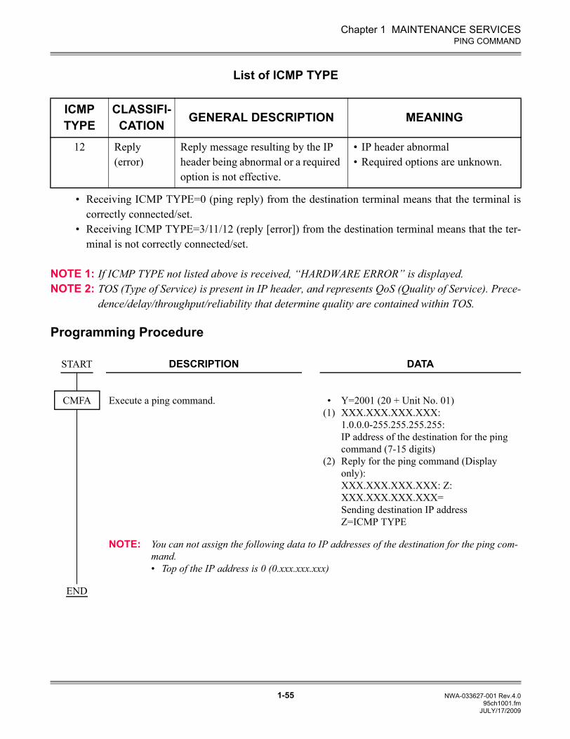
Chapter 1 MAINTENANCE SERVICES
1-55 NWA-033627-001 Rev.4.095ch1001.fm
PING COMMAND
List of ICMP TYPE
• Receiving ICMP TYPE=0 (ping reply) from the destination terminal means that the terminal iscorrectly connected/set.
• Receiving ICMP TYPE=3/11/12 (reply [error]) from the destination terminal means that the ter-minal is not correctly connected/set.
NOTE 1: If ICMP TYPE not listed above is received, “HARDWARE ERROR” is displayed.NOTE 2: TOS (Type of Service) is present in IP header, and represents QoS (Quality of Service). Prece-
dence/delay/throughput/reliability that determine quality are contained within TOS.
Programming Procedure
ICMP TYPE
CLASSIFI-CATION GENERAL DESCRIPTION MEANING
12 Reply (error)
Reply message resulting by the IP header being abnormal or a required option is not effective.
• IP header abnormal• Required options are unknown.
DESCRIPTION DATA
Execute a ping command. •(1)
(2)
Y=2001 (20 + Unit No. 01)XXX.XXX.XXX.XXX: 1.0.0.0-255.255.255.255:IP address of the destination for the ping command (7-15 digits)Reply for the ping command (Display only): XXX.XXX.XXX.XXX: Z: XXX.XXX.XXX.XXX= Sending destination IP address Z=ICMP TYPE
NOTE: You can not assign the following data to IP addresses of the destination for the ping com-mand.• Top of the IP address is 0 (0.xxx.xxx.xxx)
START
CMFA
END
JULY/17/2009
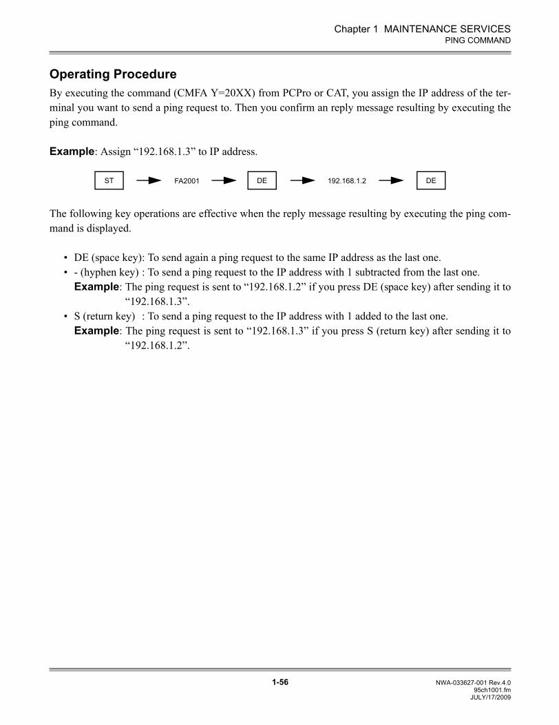
Chapter 1 MAINTENANCE SERVICES
1-56 NWA-033627-001 Rev.4.095ch1001.fm
PING COMMAND
Operating ProcedureBy executing the command (CMFA Y=20XX) from PCPro or CAT, you assign the IP address of the ter-minal you want to send a ping request to. Then you confirm an reply message resulting by executing theping command.
Example: Assign “192.168.1.3” to IP address.
The following key operations are effective when the reply message resulting by executing the ping com-mand is displayed.
• DE (space key): To send again a ping request to the same IP address as the last one.• - (hyphen key) : To send a ping request to the IP address with 1 subtracted from the last one.
Example: The ping request is sent to “192.168.1.2” if you press DE (space key) after sending it to“192.168.1.3”.
• S (return key) : To send a ping request to the IP address with 1 added to the last one.Example: The ping request is sent to “192.168.1.3” if you press S (return key) after sending it to
“192.168.1.2”.
FA2001ST DE DE192.168.1.2
JULY/17/2009
2-1 NWA-033627-001 Rev.4.095ch2001.fm
UNIVERGE SV8300System Maintenance Manual
Chapter
2
TROUBLESHOOTING
This chapter describes the precautions before troubleshooting, andthe troubleshooting procedure.
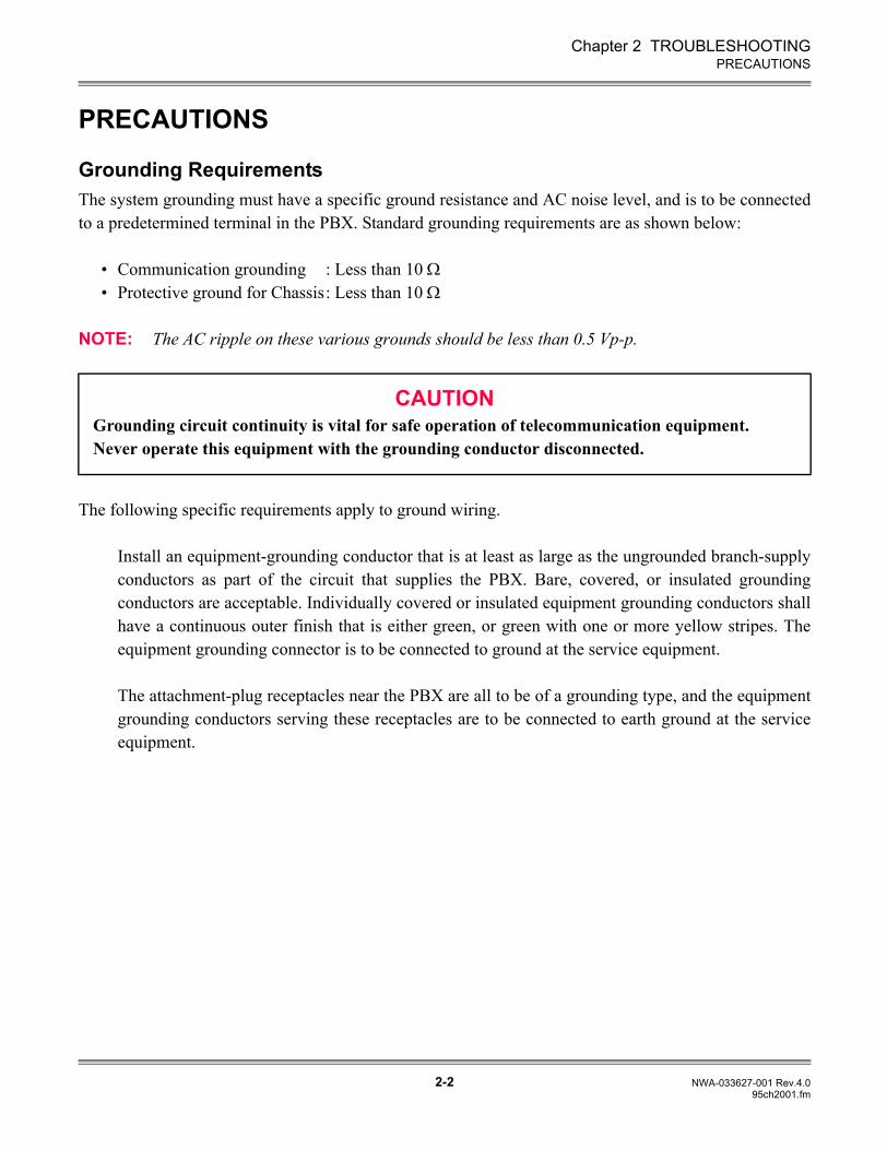
Chapter 2 TROUBLESHOOTING
2-2 NWA-033627-001 Rev.4.095ch2001.fm
PRECAUTIONS
PRECAUTIONS
Grounding RequirementsThe system grounding must have a specific ground resistance and AC noise level, and is to be connectedto a predetermined terminal in the PBX. Standard grounding requirements are as shown below:
• Communication grounding : Less than 10 Ω• Protective ground for Chassis: Less than 10 Ω
NOTE: The AC ripple on these various grounds should be less than 0.5 Vp-p.
The following specific requirements apply to ground wiring.
Install an equipment-grounding conductor that is at least as large as the ungrounded branch-supplyconductors as part of the circuit that supplies the PBX. Bare, covered, or insulated groundingconductors are acceptable. Individually covered or insulated equipment grounding conductors shallhave a continuous outer finish that is either green, or green with one or more yellow stripes. Theequipment grounding connector is to be connected to ground at the service equipment.
The attachment-plug receptacles near the PBX are all to be of a grounding type, and the equipmentgrounding conductors serving these receptacles are to be connected to earth ground at the serviceequipment.
CAUTIONGrounding circuit continuity is vital for safe operation of telecommunication equipment.Never operate this equipment with the grounding conductor disconnected.
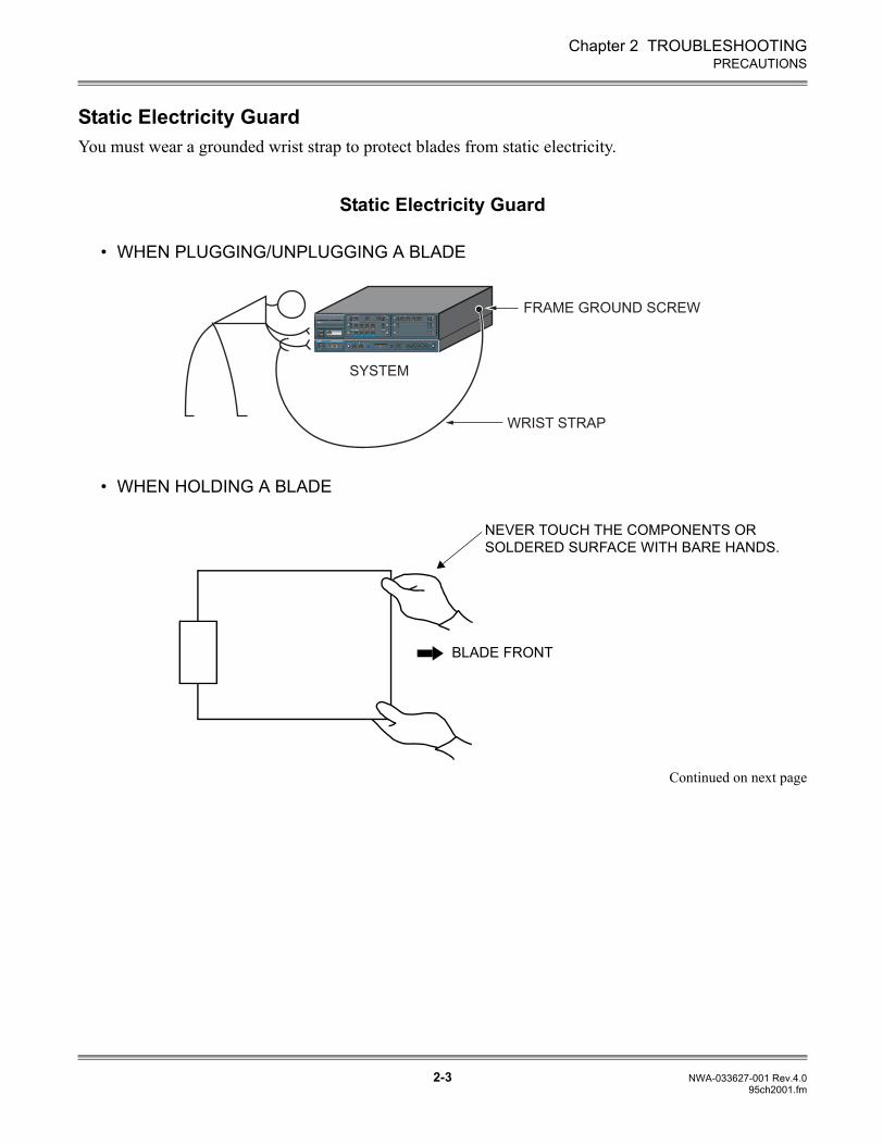
Chapter 2 TROUBLESHOOTING
2-3 NWA-033627-001 Rev.4.095ch2001.fm
PRECAUTIONS
Static Electricity GuardYou must wear a grounded wrist strap to protect blades from static electricity.
Static Electricity Guard
• WHEN PLUGGING/UNPLUGGING A BLADE
• WHEN HOLDING A BLADE
Continued on next page
WRIST STRAP
FRAME GROUND SCREW
SYSTEM
NEVER TOUCH THE COMPONENTS OR SOLDERED SURFACE WITH BARE HANDS.
BLADE FRONT
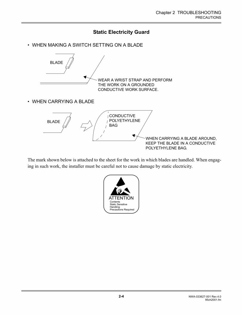
Chapter 2 TROUBLESHOOTING
2-4 NWA-033627-001 Rev.4.095ch2001.fm
PRECAUTIONS
Static Electricity Guard
• WHEN MAKING A SWITCH SETTING ON A BLADE
• WHEN CARRYING A BLADE
The mark shown below is attached to the sheet for the work in which blades are handled. When engag-ing in such work, the installer must be careful not to cause damage by static electricity.
WEAR A WRIST STRAP AND PERFORMTHE WORK ON A GROUNDEDCONDUCTIVE WORK SURFACE.
BLADE
WHEN CARRYING A BLADE AROUND, KEEP THE BLADE IN A CONDUCTIVE POLYETHYLENE BAG.
CONDUCTIVEPOLYETHYLENEBAG
BLADE
ATTENTIONContentsStatic SensitiveHandlingPrecautions Required
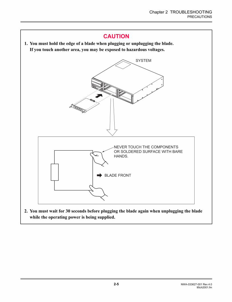
Chapter 2 TROUBLESHOOTING
2-5 NWA-033627-001 Rev.4.095ch2001.fm
PRECAUTIONS
CAUTION1. You must hold the edge of a blade when plugging or unplugging the blade.
If you touch another area, you may be exposed to hazardous voltages.
2. You must wait for 30 seconds before plugging the blade again when unplugging the blade while the operating power is being supplied.
SYSTEM
BLADE FRONT
NEVER TOUCH THE COMPONENTS
OR SOLDERED SURFACE WITH BARE
HANDS.
Chapter 2 TROUBLESHOOTING
2-6 NWA-033627-001 Rev.4.095ch2001.fm
PRECAUTIONS
Turning Power ON
(1) Turn the POWER switches of all the Units to ON.
Turning Power OFF(1) Turn the POWER switches of all the Units to OFF.
CAUTIONDo not turn the POWER switch of the Unit to OFF when the system is operating.
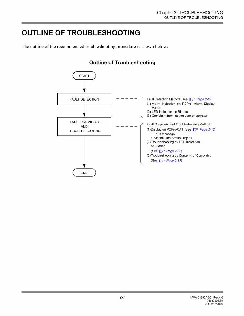
Chapter 2 TROUBLESHOOTING
2-7 NWA-033627-001 Rev.4.095ch2001.fm
OUTLINE OF TROUBLESHOOTING
OUTLINE OF TROUBLESHOOTING
The outline of the recommended troubleshooting procedure is shown below:
Outline of Troubleshooting
START
FAULT DIAGNOSISAND
TROUBLESHOOTING
Fault Detection Method (See Page 2-8)(1) Alarm Indication on PCPro, Alarm Display
Panel(2) LED Indication on Blades(3) Complaint from station user or operator
Fault Diagnosis and Troubleshooting Method(1)Display on PCPro/CAT (See Page 2-12)
• Fault Message• Station Line Status Display
(2)Troubleshooting by LED Indication on Blades(See Page 2-33)
(3)Troubleshooting by Contents of Complaint (See Page 2-37)
FAULT DETECTION
END
JULY/17/2009
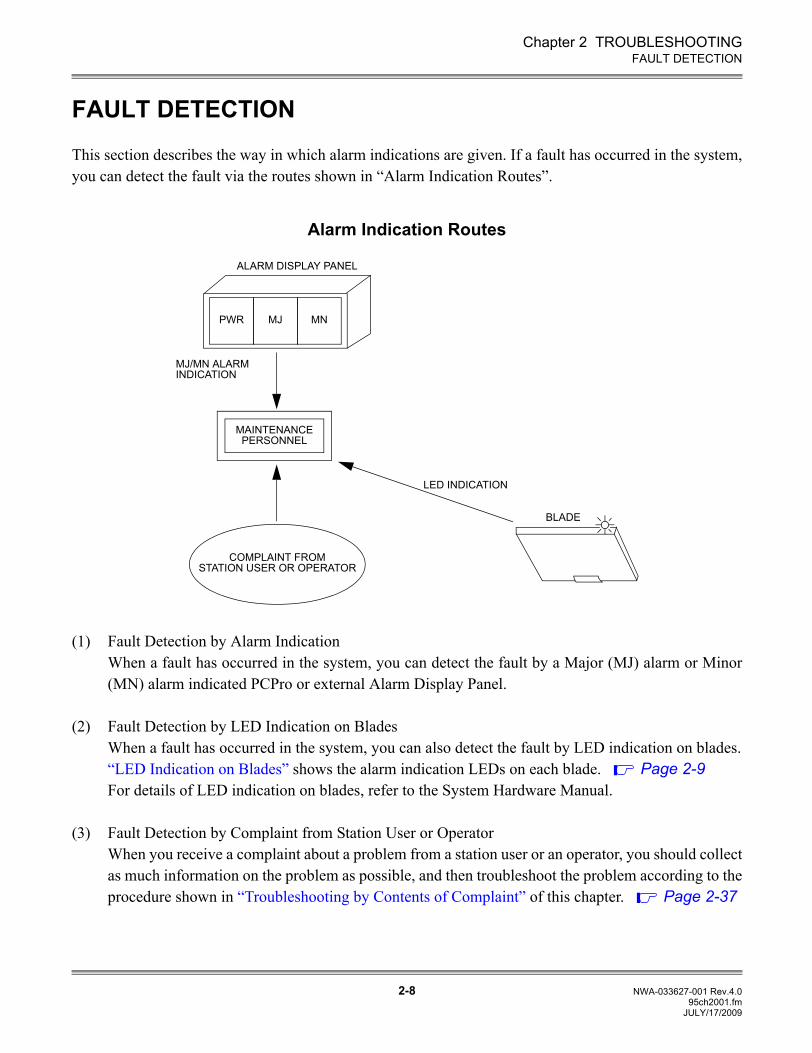
Chapter 2 TROUBLESHOOTING
2-8 NWA-033627-001 Rev.4.095ch2001.fm
FAULT DETECTION
FAULT DETECTION
This section describes the way in which alarm indications are given. If a fault has occurred in the system,you can detect the fault via the routes shown in “Alarm Indication Routes”.
Alarm Indication Routes
(1) Fault Detection by Alarm IndicationWhen a fault has occurred in the system, you can detect the fault by a Major (MJ) alarm or Minor(MN) alarm indicated PCPro or external Alarm Display Panel.
(2) Fault Detection by LED Indication on BladesWhen a fault has occurred in the system, you can also detect the fault by LED indication on blades.“LED Indication on Blades” shows the alarm indication LEDs on each blade. Page 2-9For details of LED indication on blades, refer to the System Hardware Manual.
(3) Fault Detection by Complaint from Station User or OperatorWhen you receive a complaint about a problem from a station user or an operator, you should collectas much information on the problem as possible, and then troubleshoot the problem according to theprocedure shown in “Troubleshooting by Contents of Complaint” of this chapter. Page 2-37
LED INDICATION
BLADE
MAINTENANCEPERSONNEL
COMPLAINT FROMSTATION USER OR OPERATOR
PWR MJ MN
ALARM DISPLAY PANEL
MJ/MN ALARMINDICATION
JULY/17/2009
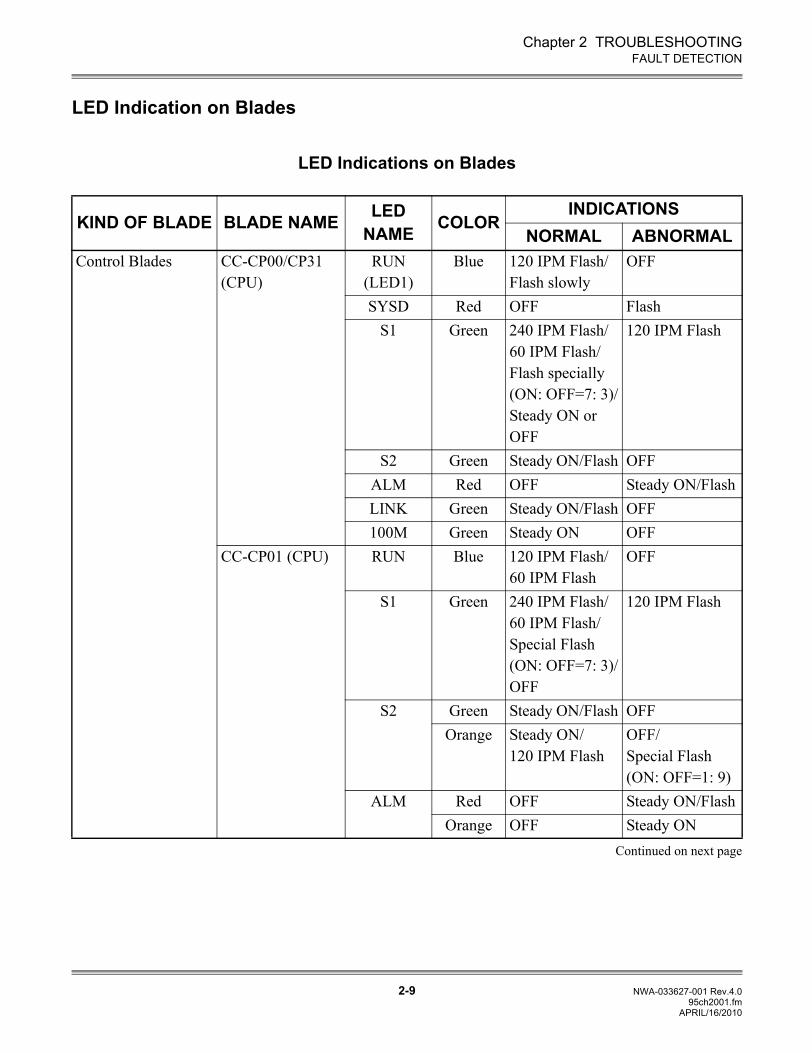
Chapter 2 TROUBLESHOOTING
2-9 NWA-033627-001 Rev.4.095ch2001.fm
FAULT DETECTION
LED Indication on Blades
LED Indications on Blades
KIND OF BLADE BLADE NAME LED NAME COLOR
INDICATIONSNORMAL ABNORMAL
Control Blades CC-CP00/CP31 (CPU)
RUN (LED1)
Blue 120 IPM Flash/Flash slowly
OFF
SYSD Red OFF FlashS1 Green 240 IPM Flash/
60 IPM Flash/Flash specially (ON: OFF=7: 3)/Steady ON or OFF
120 IPM Flash
S2 Green Steady ON/Flash OFFALM Red OFF Steady ON/FlashLINK Green Steady ON/Flash OFF100M Green Steady ON OFF
CC-CP01 (CPU) RUN Blue 120 IPM Flash/60 IPM Flash
OFF
S1 Green 240 IPM Flash/60 IPM Flash/Special Flash (ON: OFF=7: 3)/OFF
120 IPM Flash
S2 Green Steady ON/Flash OFFOrange Steady ON/
120 IPM FlashOFF/Special Flash (ON: OFF=1: 9)
ALM Red OFF Steady ON/FlashOrange OFF Steady ON
Continued on next page
APRIL/16/2010
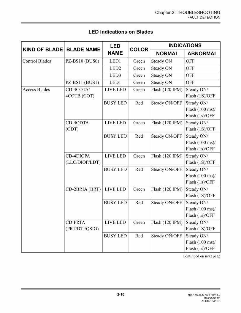
Chapter 2 TROUBLESHOOTING
2-10 NWA-033627-001 Rev.4.095ch2001.fm
FAULT DETECTION
LED Indications on Blades
KIND OF BLADE BLADE NAME LED NAME COLOR
INDICATIONSNORMAL ABNORMAL
Control Blades PZ-BS10 (BUS0) LED1 Green Steady ON OFFLED2 Green Steady ON OFFLED3 Green Steady ON OFF
PZ-BS11 (BUS1) LED1 Green Steady ON OFFAccess Blades CD-4COTA/
4COTB (COT)LIVE LED Green Flash (120 IPM) Steady ON/
Flash (1S)/OFFBUSY LED Red Steady ON/OFF Steady ON/
Flash (100 ms)/Flash (1s)/OFF
CD-4ODTA (ODT)
LIVE LED Green Flash (120 IPM) Steady ON/Flash (1S)/OFF
BUSY LED Red Steady ON/OFF Steady ON/Flash (100 ms)/Flash (1s)/OFF
CD-4DIOPA (LLC/DIOP/LDT)
LIVE LED Green Flash (120 IPM) Steady ON/Flash (1S)/OFF
BUSY LED Red Steady ON/OFF Steady ON/Flash (100 ms)/Flash (1s)/OFF
CD-2BRIA (BRT) LIVE LED Green Flash (120 IPM) Steady ON/Flash (1S)/OFF
BUSY LED Red Steady ON/OFF Steady ON/Flash (100 ms)/Flash (1s)/OFF
CD-PRTA (PRT/DTI/QSIG)
LIVE LED Green Flash (120 IPM) Steady ON/Flash (1S)/OFF
BUSY LED Red Steady ON/OFF Steady ON/Flash (100 ms)/Flash (1s)/OFF
Continued on next page
APRIL/16/2010
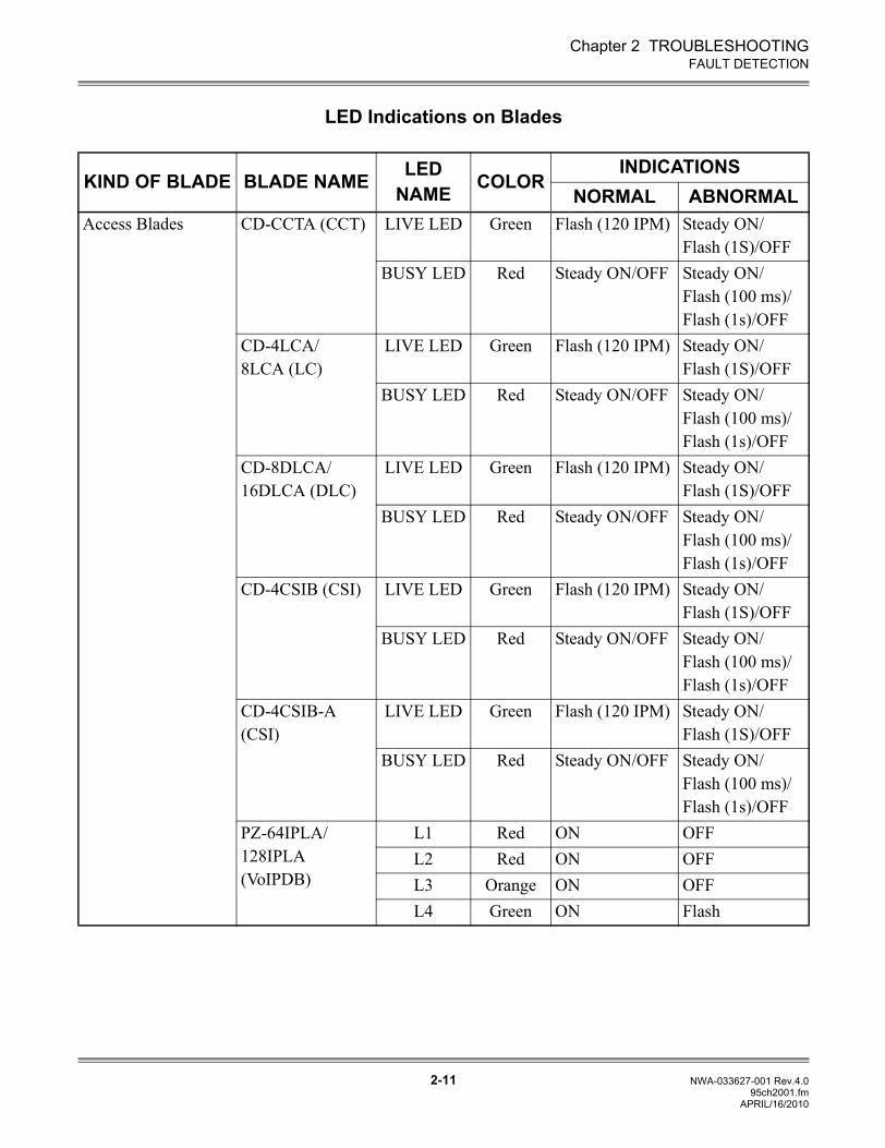
Chapter 2 TROUBLESHOOTING
2-11 NWA-033627-001 Rev.4.095ch2001.fm
FAULT DETECTION
LED Indications on Blades
KIND OF BLADE BLADE NAME LED NAME COLOR
INDICATIONSNORMAL ABNORMAL
Access Blades CD-CCTA (CCT) LIVE LED Green Flash (120 IPM) Steady ON/Flash (1S)/OFF
BUSY LED Red Steady ON/OFF Steady ON/Flash (100 ms)/Flash (1s)/OFF
CD-4LCA/8LCA (LC)
LIVE LED Green Flash (120 IPM) Steady ON/Flash (1S)/OFF
BUSY LED Red Steady ON/OFF Steady ON/Flash (100 ms)/Flash (1s)/OFF
CD-8DLCA/16DLCA (DLC)
LIVE LED Green Flash (120 IPM) Steady ON/Flash (1S)/OFF
BUSY LED Red Steady ON/OFF Steady ON/Flash (100 ms)/Flash (1s)/OFF
CD-4CSIB (CSI) LIVE LED Green Flash (120 IPM) Steady ON/Flash (1S)/OFF
BUSY LED Red Steady ON/OFF Steady ON/Flash (100 ms)/Flash (1s)/OFF
CD-4CSIB-A (CSI)
LIVE LED Green Flash (120 IPM) Steady ON/Flash (1S)/OFF
BUSY LED Red Steady ON/OFF Steady ON/Flash (100 ms)/Flash (1s)/OFF
PZ-64IPLA/128IPLA (VoIPDB)
L1 Red ON OFFL2 Red ON OFFL3 Orange ON OFFL4 Green ON Flash
APRIL/16/2010
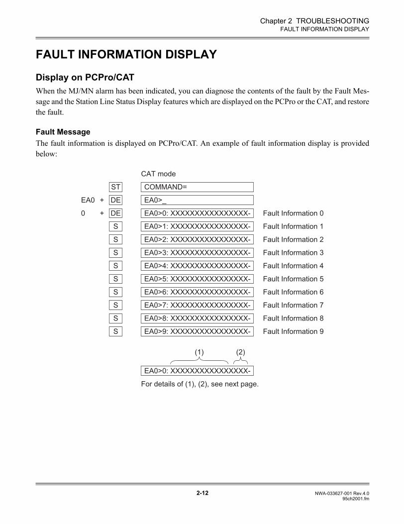
Chapter 2 TROUBLESHOOTING
2-12 NWA-033627-001 Rev.4.095ch2001.fm
FAULT INFORMATION DISPLAY
FAULT INFORMATION DISPLAY
Display on PCPro/CATWhen the MJ/MN alarm has been indicated, you can diagnose the contents of the fault by the Fault Mes-sage and the Station Line Status Display features which are displayed on the PCPro or the CAT, and restorethe fault.
Fault MessageThe fault information is displayed on PCPro/CAT. An example of fault information display is providedbelow:
DE EA0>0: XXXXXXXXXXXXXXXX- Fault Information 0
DE EA0>_
ST COMMAND=
S EA0>1: XXXXXXXXXXXXXXXX- Fault Information 1
S EA0>2: XXXXXXXXXXXXXXXX- Fault Information 2
S EA0>3: XXXXXXXXXXXXXXXX- Fault Information 3
S EA0>4: XXXXXXXXXXXXXXXX- Fault Information 4
S EA0>5: XXXXXXXXXXXXXXXX- Fault Information 5
S EA0>6: XXXXXXXXXXXXXXXX- Fault Information 6
S EA0>7: XXXXXXXXXXXXXXXX- Fault Information 7
S EA0>8: XXXXXXXXXXXXXXXX- Fault Information 8
S EA0>9: XXXXXXXXXXXXXXXX- Fault Information 9
For details of (1), (2), see next page.
(1)
CAT mode
EA0 +
0 +
EA0>0: XXXXXXXXXXXXXXXX-
(2)
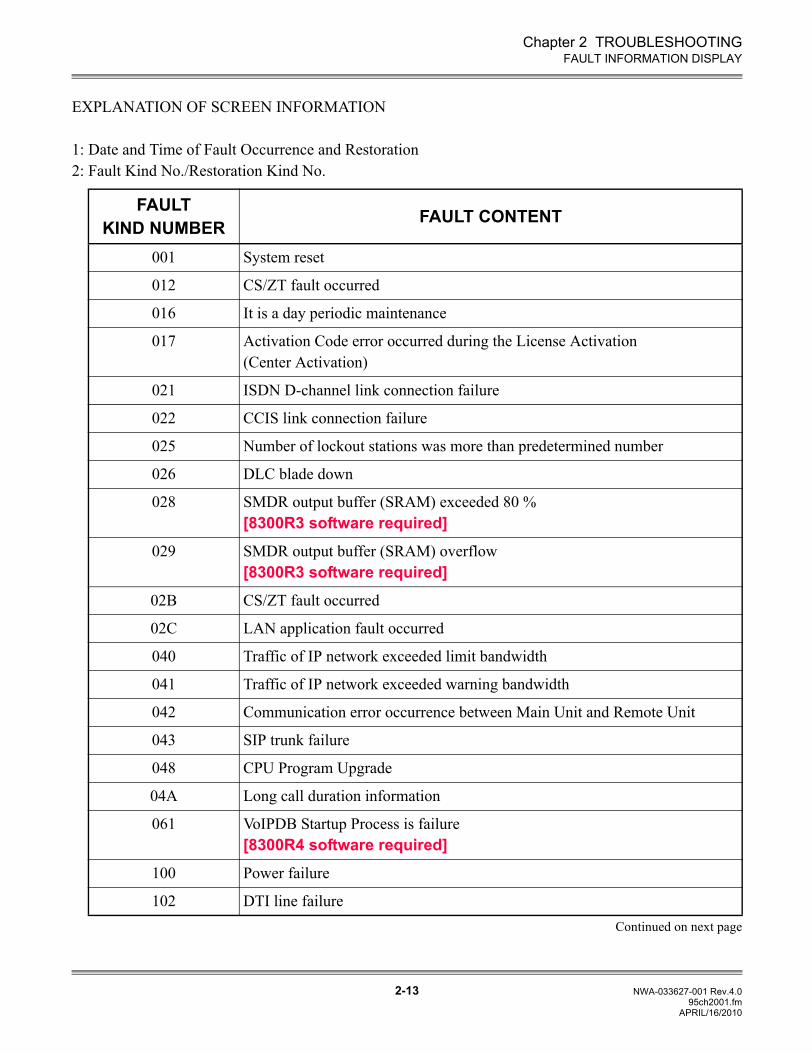
Chapter 2 TROUBLESHOOTING
2-13 NWA-033627-001 Rev.4.095ch2001.fm
FAULT INFORMATION DISPLAY
EXPLANATION OF SCREEN INFORMATION
1: Date and Time of Fault Occurrence and Restoration2: Fault Kind No./Restoration Kind No.
FAULTKIND NUMBER FAULT CONTENT
001 System reset
012 CS/ZT fault occurred
016 It is a day periodic maintenance
017 Activation Code error occurred during the License Activation (Center Activation)
021 ISDN D-channel link connection failure
022 CCIS link connection failure
025 Number of lockout stations was more than predetermined number
026 DLC blade down
028 SMDR output buffer (SRAM) exceeded 80 %[8300R3 software required]
029 SMDR output buffer (SRAM) overflow[8300R3 software required]
02B CS/ZT fault occurred
02C LAN application fault occurred
040 Traffic of IP network exceeded limit bandwidth
041 Traffic of IP network exceeded warning bandwidth
042 Communication error occurrence between Main Unit and Remote Unit
043 SIP trunk failure
048 CPU Program Upgrade
04A Long call duration information
061 VoIPDB Startup Process is failure[8300R4 software required]
100 Power failure
102 DTI line failureContinued on next page
APRIL/16/2010
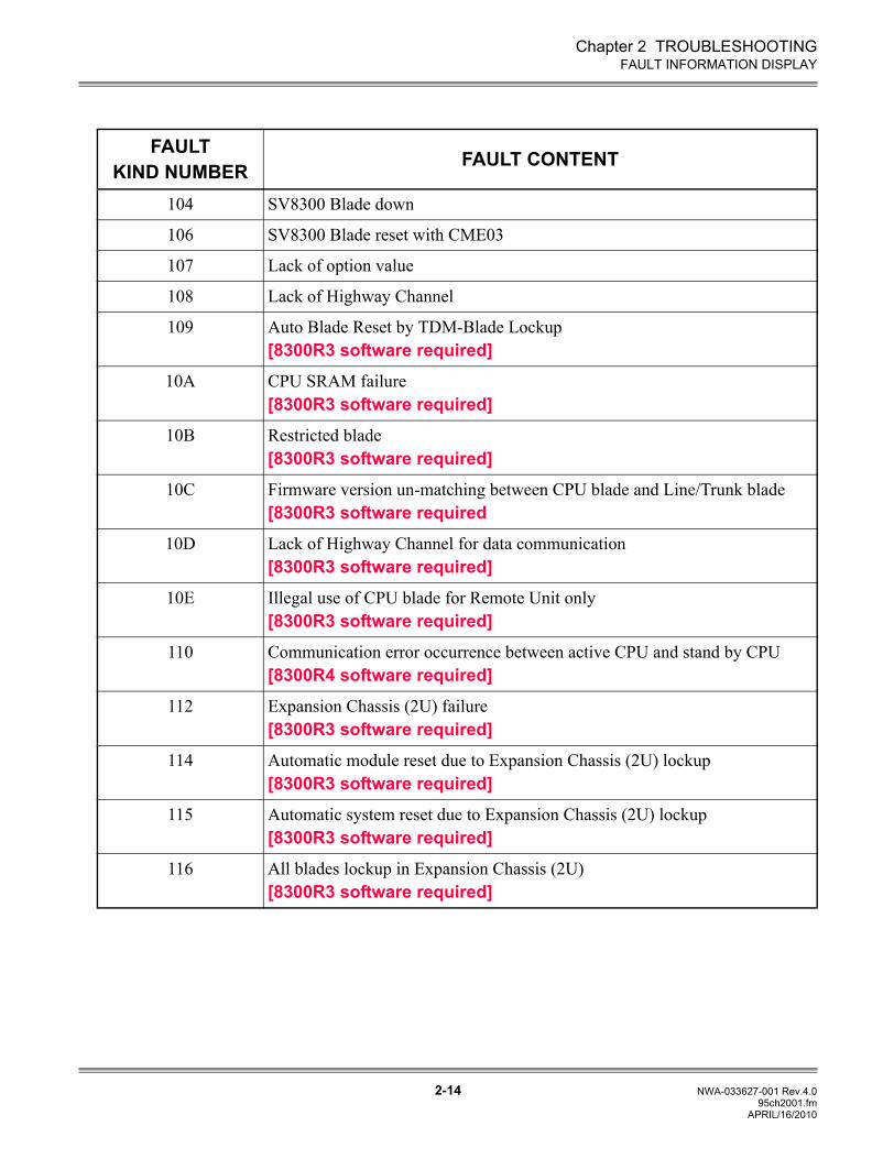
Chapter 2 TROUBLESHOOTING
2-14 NWA-033627-001 Rev.4.095ch2001.fm
FAULT INFORMATION DISPLAY
FAULTKIND NUMBER FAULT CONTENT
104 SV8300 Blade down
106 SV8300 Blade reset with CME03
107 Lack of option value
108 Lack of Highway Channel
109 Auto Blade Reset by TDM-Blade Lockup[8300R3 software required]
10A CPU SRAM failure[8300R3 software required]
10B Restricted blade[8300R3 software required]
10C Firmware version un-matching between CPU blade and Line/Trunk blade[8300R3 software required
10D Lack of Highway Channel for data communication[8300R3 software required]
10E Illegal use of CPU blade for Remote Unit only[8300R3 software required]
110 Communication error occurrence between active CPU and stand by CPU[8300R4 software required]
112 Expansion Chassis (2U) failure[8300R3 software required]
114 Automatic module reset due to Expansion Chassis (2U) lockup[8300R3 software required]
115 Automatic system reset due to Expansion Chassis (2U) lockup[8300R3 software required]
116 All blades lockup in Expansion Chassis (2U)[8300R3 software required]
APRIL/16/2010
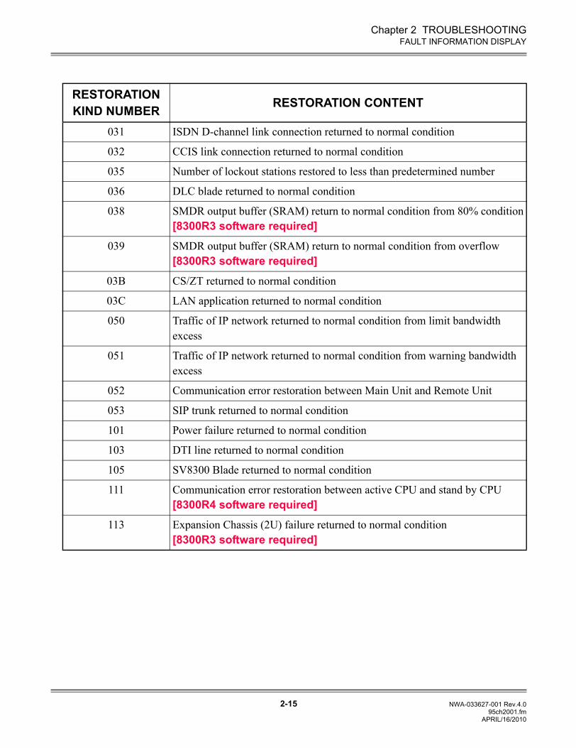
Chapter 2 TROUBLESHOOTING
2-15 NWA-033627-001 Rev.4.095ch2001.fm
FAULT INFORMATION DISPLAY
RESTORATIONKIND NUMBER RESTORATION CONTENT
031 ISDN D-channel link connection returned to normal condition
032 CCIS link connection returned to normal condition
035 Number of lockout stations restored to less than predetermined number
036 DLC blade returned to normal condition
038 SMDR output buffer (SRAM) return to normal condition from 80% condition[8300R3 software required]
039 SMDR output buffer (SRAM) return to normal condition from overflow[8300R3 software required]
03B CS/ZT returned to normal condition
03C LAN application returned to normal condition
050 Traffic of IP network returned to normal condition from limit bandwidth excess
051 Traffic of IP network returned to normal condition from warning bandwidth excess
052 Communication error restoration between Main Unit and Remote Unit
053 SIP trunk returned to normal condition
101 Power failure returned to normal condition
103 DTI line returned to normal condition
105 SV8300 Blade returned to normal condition
111 Communication error restoration between active CPU and stand by CPU[8300R4 software required]
113 Expansion Chassis (2U) failure returned to normal condition[8300R3 software required]
APRIL/16/2010
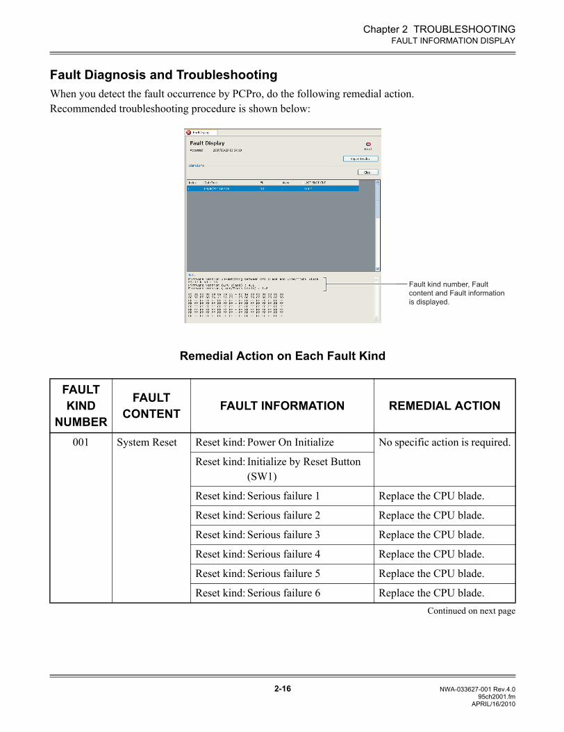
Chapter 2 TROUBLESHOOTING
2-16 NWA-033627-001 Rev.4.095ch2001.fm
FAULT INFORMATION DISPLAY
Fault Diagnosis and TroubleshootingWhen you detect the fault occurrence by PCPro, do the following remedial action.Recommended troubleshooting procedure is shown below:
Remedial Action on Each Fault Kind
FAULT KIND
NUMBER
FAULT CONTENT FAULT INFORMATION REMEDIAL ACTION
001 System Reset Reset kind: Power On Initialize No specific action is required.
Reset kind: Initialize by Reset Button (SW1)
Reset kind: Serious failure 1 Replace the CPU blade.
Reset kind: Serious failure 2 Replace the CPU blade.
Reset kind: Serious failure 3 Replace the CPU blade.
Reset kind: Serious failure 4 Replace the CPU blade.
Reset kind: Serious failure 5 Replace the CPU blade.
Reset kind: Serious failure 6 Replace the CPU blade.Continued on next page
Fault kind number, Fault
content and Fault information
is displayed.
APRIL/16/2010
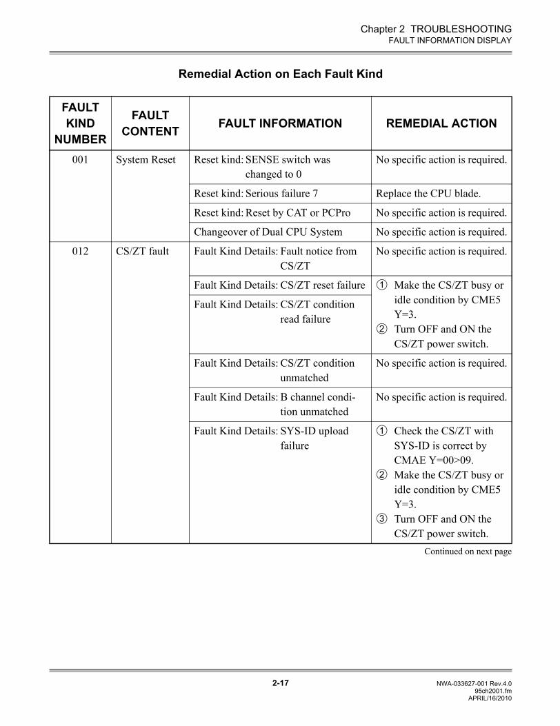
Chapter 2 TROUBLESHOOTING
2-17 NWA-033627-001 Rev.4.095ch2001.fm
FAULT INFORMATION DISPLAY
Remedial Action on Each Fault Kind
FAULT KIND
NUMBER
FAULT CONTENT FAULT INFORMATION REMEDIAL ACTION
001 System Reset Reset kind: SENSE switch was changed to 0
No specific action is required.
Reset kind: Serious failure 7 Replace the CPU blade.
Reset kind: Reset by CAT or PCPro No specific action is required.
Changeover of Dual CPU System No specific action is required.
012 CS/ZT fault Fault Kind Details: Fault notice from CS/ZT
No specific action is required.
Fault Kind Details: CS/ZT reset failure Make the CS/ZT busy or idle condition by CME5 Y=3. Turn OFF and ON the CS/ZT power switch.
Fault Kind Details: CS/ZT condition read failure
Fault Kind Details: CS/ZT condition unmatched
No specific action is required.
Fault Kind Details: B channel condi-tion unmatched
No specific action is required.
Fault Kind Details: SYS-ID upload failure
Check the CS/ZT with SYS-ID is correct by CMAE Y=00>09.Make the CS/ZT busy or idle condition by CME5 Y=3.Turn OFF and ON the CS/ZT power switch.
Continued on next page
1
2
1
2
3
APRIL/16/2010
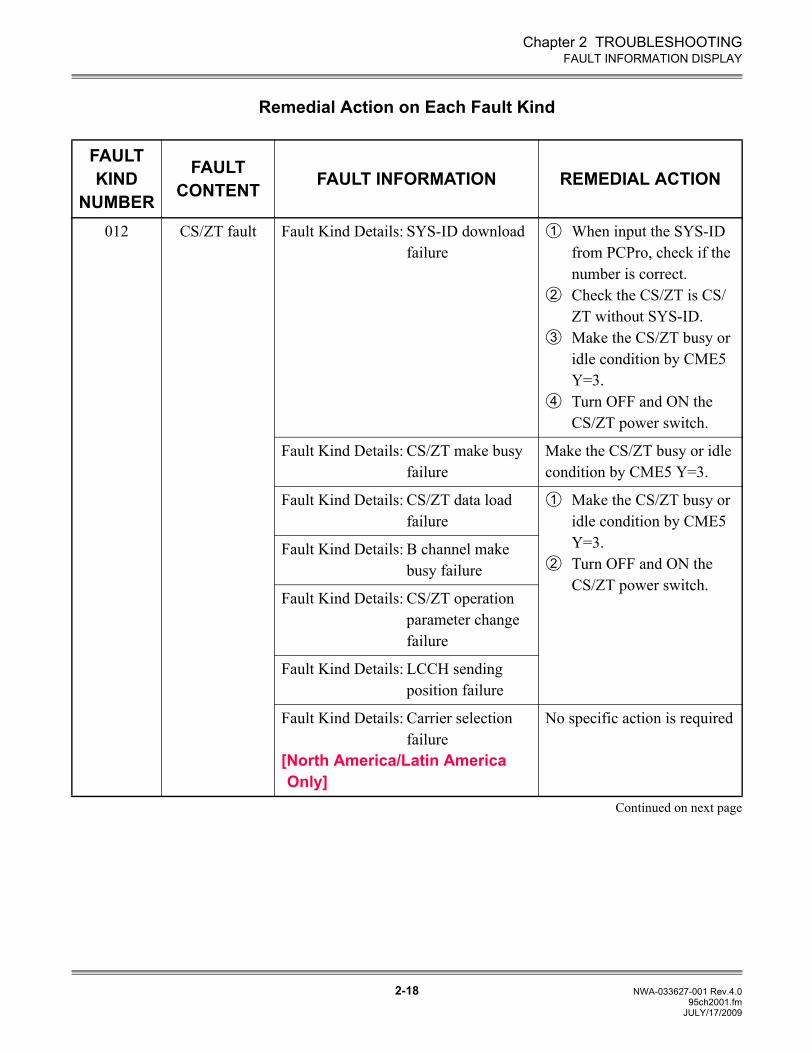
Chapter 2 TROUBLESHOOTING
2-18 NWA-033627-001 Rev.4.095ch2001.fm
FAULT INFORMATION DISPLAY
Remedial Action on Each Fault Kind
FAULT KIND
NUMBER
FAULT CONTENT FAULT INFORMATION REMEDIAL ACTION
012 CS/ZT fault Fault Kind Details: SYS-ID download failure
When input the SYS-ID from PCPro, check if the number is correct. Check the CS/ZT is CS/ZT without SYS-ID.Make the CS/ZT busy or idle condition by CME5 Y=3.Turn OFF and ON the CS/ZT power switch.
Fault Kind Details: CS/ZT make busy failure
Make the CS/ZT busy or idle condition by CME5 Y=3.
Fault Kind Details: CS/ZT data load failure
Make the CS/ZT busy or idle condition by CME5 Y=3. Turn OFF and ON the CS/ZT power switch.
Fault Kind Details: B channel make busy failure
Fault Kind Details: CS/ZT operation parameter change failure
Fault Kind Details: LCCH sending position failure
Fault Kind Details: Carrier selection failure
[North America/Latin America Only]
No specific action is required
Continued on next page
1
2
3
4
1
2
JULY/17/2009
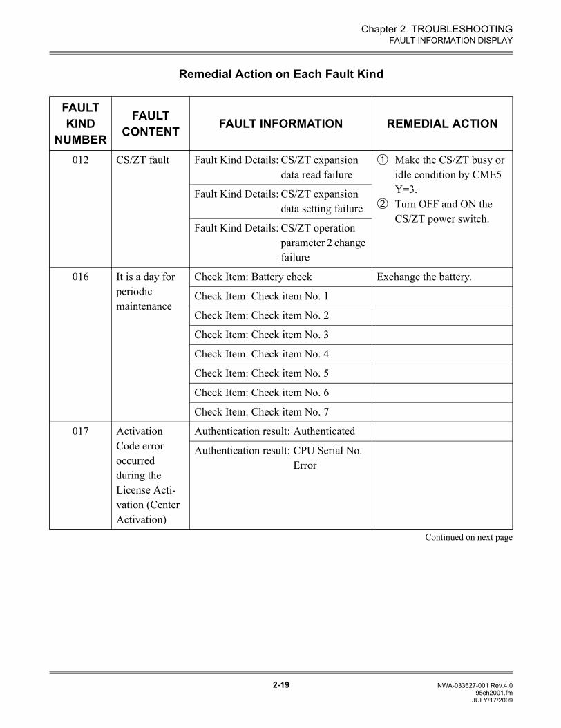
Chapter 2 TROUBLESHOOTING
2-19 NWA-033627-001 Rev.4.095ch2001.fm
FAULT INFORMATION DISPLAY
Remedial Action on Each Fault Kind
FAULT KIND
NUMBER
FAULT CONTENT FAULT INFORMATION REMEDIAL ACTION
012 CS/ZT fault Fault Kind Details: CS/ZT expansion data read failure
Make the CS/ZT busy or idle condition by CME5 Y=3. Turn OFF and ON the CS/ZT power switch.
Fault Kind Details: CS/ZT expansion data setting failure
Fault Kind Details: CS/ZT operation parameter 2 change failure
016 It is a day for periodic maintenance
Check Item: Battery check Exchange the battery.
Check Item: Check item No. 1
Check Item: Check item No. 2
Check Item: Check item No. 3
Check Item: Check item No. 4
Check Item: Check item No. 5
Check Item: Check item No. 6
Check Item: Check item No. 7
017 Activation Code error occurred during the License Acti-vation (Center Activation)
Authentication result: Authenticated
Authentication result: CPU Serial No. Error
Continued on next page
1
2
JULY/17/2009
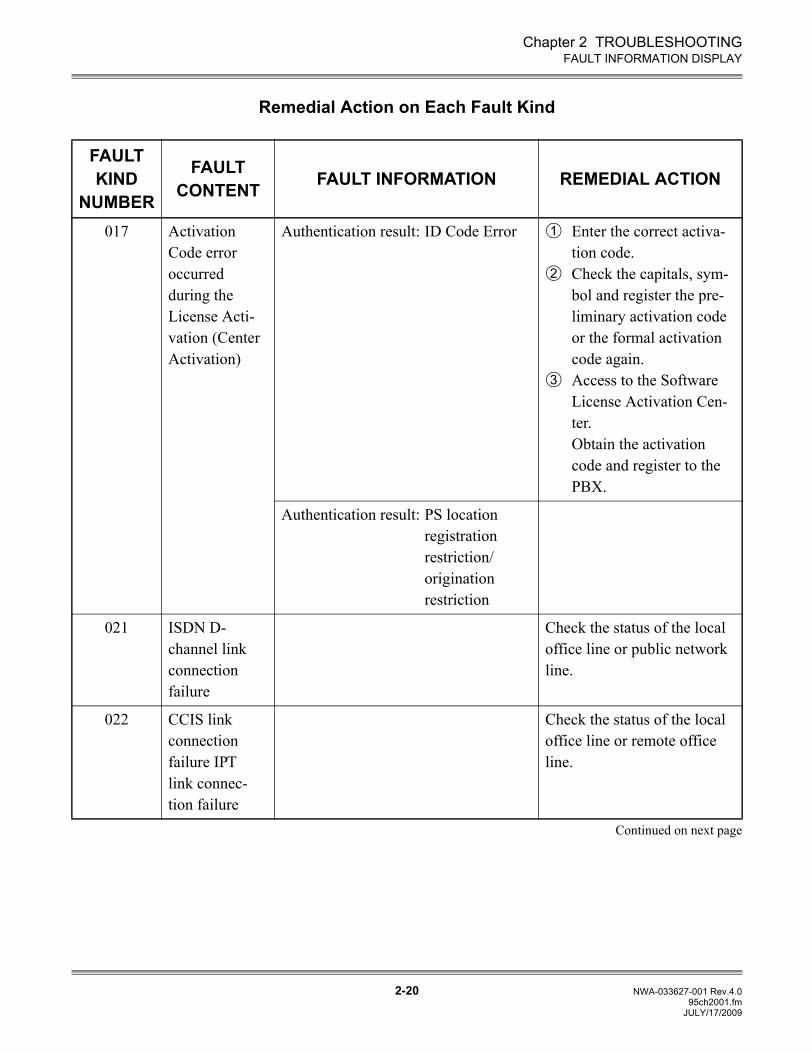
Chapter 2 TROUBLESHOOTING
2-20 NWA-033627-001 Rev.4.095ch2001.fm
FAULT INFORMATION DISPLAY
Remedial Action on Each Fault Kind
FAULT KIND
NUMBER
FAULT CONTENT FAULT INFORMATION REMEDIAL ACTION
017 Activation Code error occurred during the License Acti-vation (Center Activation)
Authentication result: ID Code Error Enter the correct activa-tion code.Check the capitals, sym-bol and register the pre-liminary activation code or the formal activation code again.Access to the Software License Activation Cen-ter. Obtain the activation code and register to the PBX.
Authentication result: PS location registration restriction/origination restriction
021 ISDN D-channel link connection failure
Check the status of the local office line or public network line.
022 CCIS link connection failure IPT link connec-tion failure
Check the status of the local office line or remote office line.
Continued on next page
1
2
3
JULY/17/2009
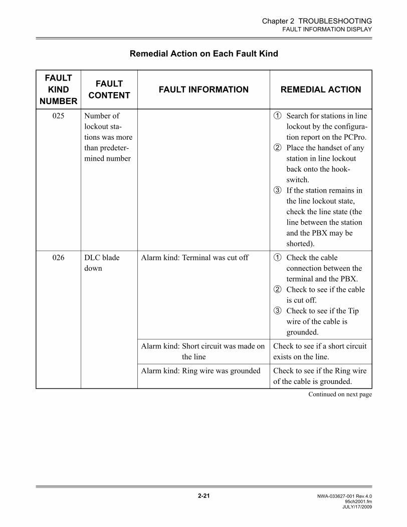
Chapter 2 TROUBLESHOOTING
2-21 NWA-033627-001 Rev.4.095ch2001.fm
FAULT INFORMATION DISPLAY
Remedial Action on Each Fault Kind
FAULT KIND
NUMBER
FAULT CONTENT FAULT INFORMATION REMEDIAL ACTION
025 Number of lockout sta-tions was more than predeter-mined number
Search for stations in line lockout by the configura-tion report on the PCPro.Place the handset of any station in line lockout back onto the hook-switch.If the station remains in the line lockout state, check the line state (the line between the station and the PBX may be shorted).
026 DLC blade down
Alarm kind: Terminal was cut off Check the cable connection between the terminal and the PBX.Check to see if the cable is cut off.Check to see if the Tip wire of the cable is grounded.
Alarm kind: Short circuit was made on the line
Check to see if a short circuit exists on the line.
Alarm kind: Ring wire was grounded Check to see if the Ring wire of the cable is grounded.
Continued on next page
1
2
3
1
2
3
JULY/17/2009
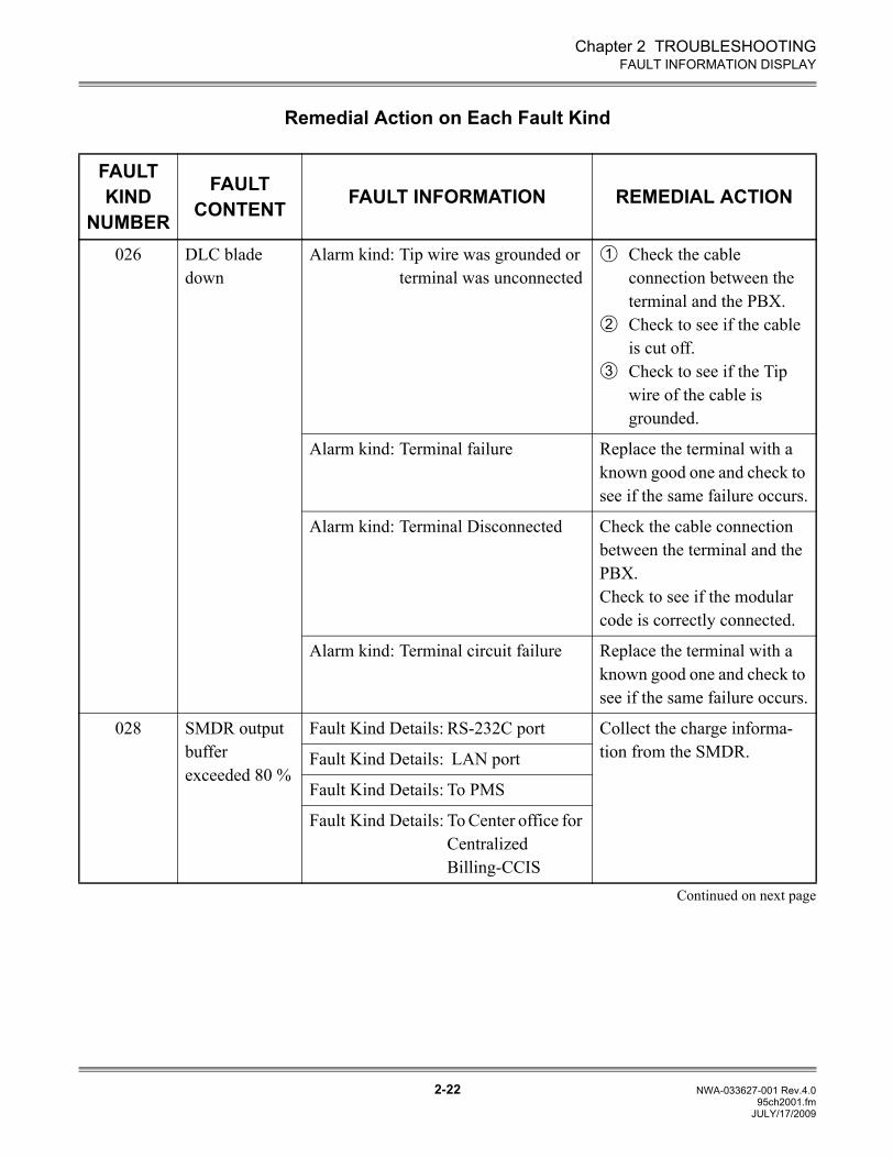
Chapter 2 TROUBLESHOOTING
2-22 NWA-033627-001 Rev.4.095ch2001.fm
FAULT INFORMATION DISPLAY
Remedial Action on Each Fault Kind
FAULT KIND
NUMBER
FAULT CONTENT FAULT INFORMATION REMEDIAL ACTION
026 DLC blade down
Alarm kind: Tip wire was grounded or terminal was unconnected
Check the cable connection between the terminal and the PBX.Check to see if the cable is cut off.Check to see if the Tip wire of the cable is grounded.
Alarm kind: Terminal failure Replace the terminal with a known good one and check to see if the same failure occurs.
Alarm kind: Terminal Disconnected Check the cable connection between the terminal and the PBX.Check to see if the modular code is correctly connected.
Alarm kind: Terminal circuit failure Replace the terminal with a known good one and check to see if the same failure occurs.
028 SMDR output buffer exceeded 80 %
Fault Kind Details: RS-232C port Collect the charge informa-tion from the SMDR.Fault Kind Details: LAN port
Fault Kind Details: To PMS
Fault Kind Details: To Center office for Centralized Billing-CCIS
Continued on next page
1
2
3
JULY/17/2009
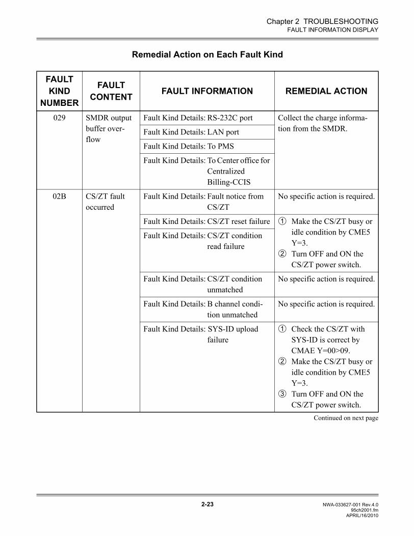
Chapter 2 TROUBLESHOOTING
2-23 NWA-033627-001 Rev.4.095ch2001.fm
FAULT INFORMATION DISPLAY
Remedial Action on Each Fault Kind
FAULT KIND
NUMBER
FAULT CONTENT FAULT INFORMATION REMEDIAL ACTION
029 SMDR output buffer over-flow
Fault Kind Details: RS-232C port Collect the charge informa-tion from the SMDR.Fault Kind Details: LAN port
Fault Kind Details: To PMS
Fault Kind Details: To Center office for Centralized Billing-CCIS
02B CS/ZT fault occurred
Fault Kind Details: Fault notice from CS/ZT
No specific action is required.
Fault Kind Details: CS/ZT reset failure Make the CS/ZT busy or idle condition by CME5 Y=3.Turn OFF and ON the CS/ZT power switch.
Fault Kind Details: CS/ZT condition read failure
Fault Kind Details: CS/ZT condition unmatched
No specific action is required.
Fault Kind Details: B channel condi-tion unmatched
No specific action is required.
Fault Kind Details: SYS-ID upload failure
Check the CS/ZT with SYS-ID is correct by CMAE Y=00>09.Make the CS/ZT busy or idle condition by CME5 Y=3.Turn OFF and ON the CS/ZT power switch.
Continued on next page
1
2
1
2
3
APRIL/16/2010
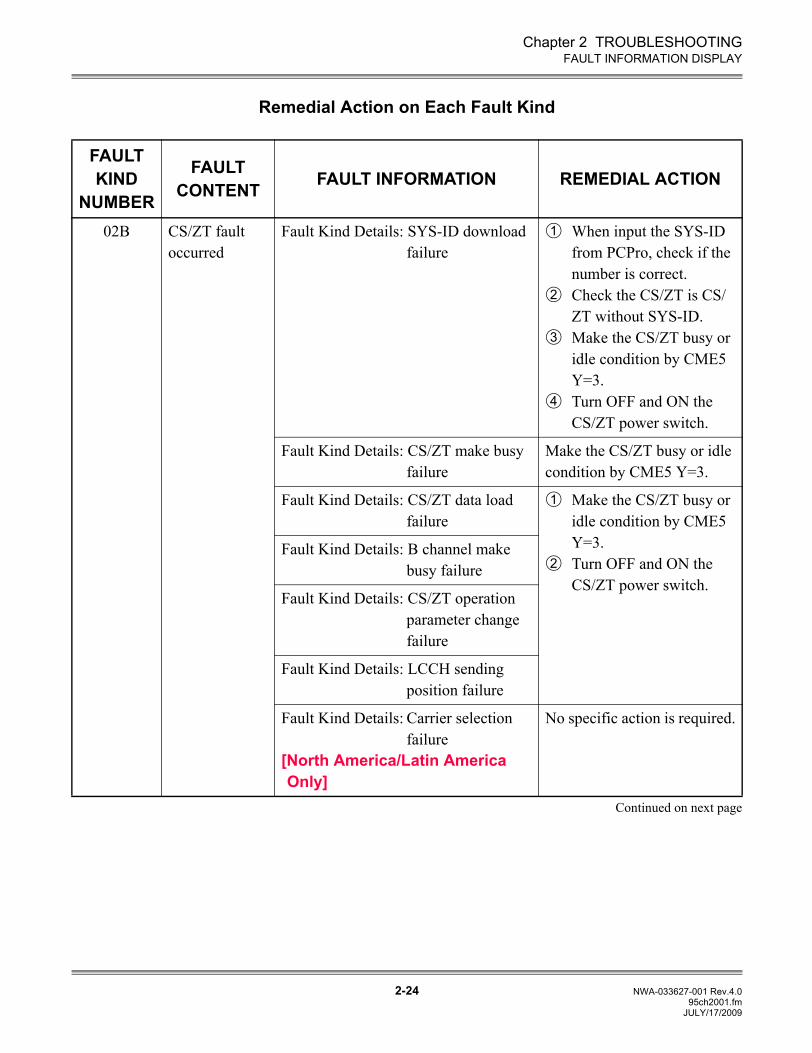
Chapter 2 TROUBLESHOOTING
2-24 NWA-033627-001 Rev.4.095ch2001.fm
FAULT INFORMATION DISPLAY
Remedial Action on Each Fault Kind
FAULT KIND
NUMBER
FAULT CONTENT FAULT INFORMATION REMEDIAL ACTION
02B CS/ZT fault occurred
Fault Kind Details: SYS-ID download failure
When input the SYS-ID from PCPro, check if the number is correct.Check the CS/ZT is CS/ZT without SYS-ID.Make the CS/ZT busy or idle condition by CME5 Y=3.Turn OFF and ON the CS/ZT power switch.
Fault Kind Details: CS/ZT make busy failure
Make the CS/ZT busy or idle condition by CME5 Y=3.
Fault Kind Details: CS/ZT data load failure
Make the CS/ZT busy or idle condition by CME5 Y=3.Turn OFF and ON the CS/ZT power switch.
Fault Kind Details: B channel make busy failure
Fault Kind Details: CS/ZT operation parameter change failure
Fault Kind Details: LCCH sending position failure
Fault Kind Details: Carrier selection failure
[North America/Latin America Only]
No specific action is required.
Continued on next page
1
2
3
4
1
2
JULY/17/2009
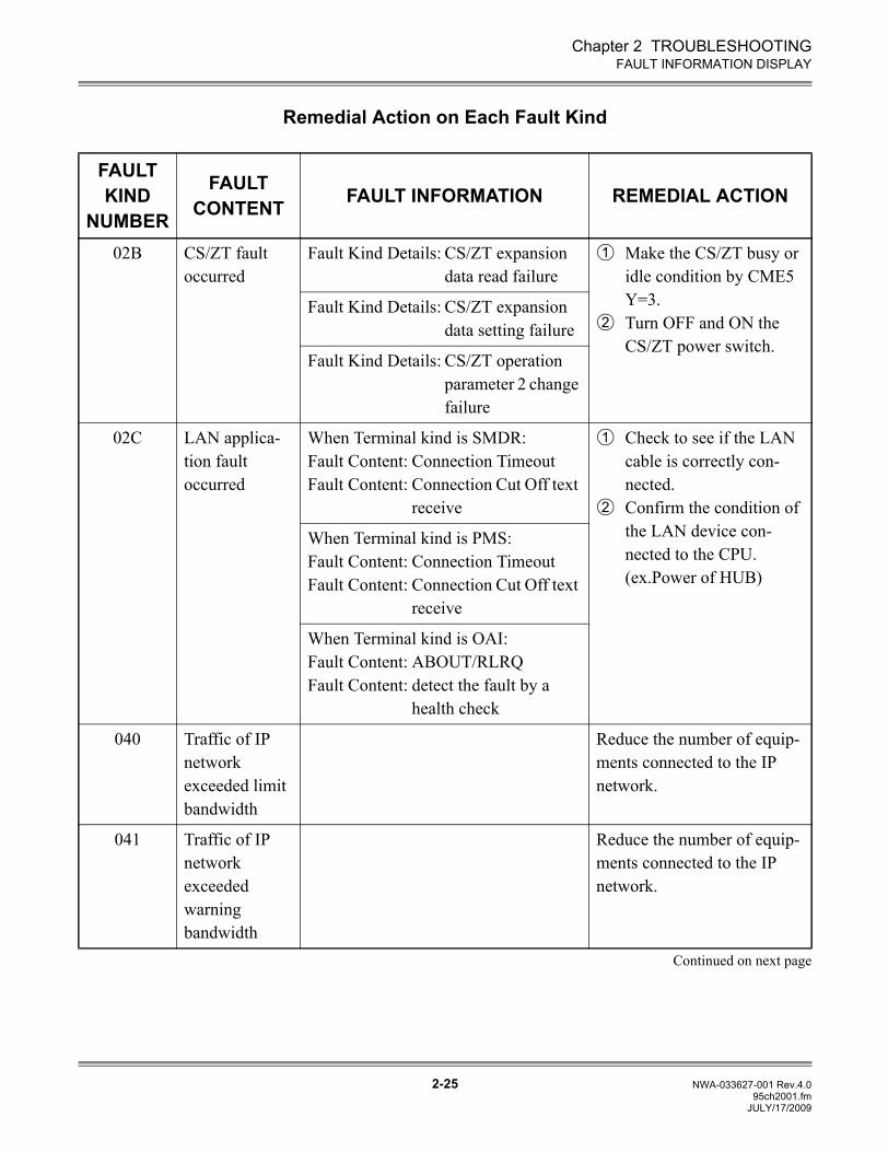
Chapter 2 TROUBLESHOOTING
2-25 NWA-033627-001 Rev.4.095ch2001.fm
FAULT INFORMATION DISPLAY
Remedial Action on Each Fault Kind
FAULT KIND
NUMBER
FAULT CONTENT FAULT INFORMATION REMEDIAL ACTION
02B CS/ZT fault occurred
Fault Kind Details: CS/ZT expansion data read failure
Make the CS/ZT busy or idle condition by CME5 Y=3.Turn OFF and ON the CS/ZT power switch.
Fault Kind Details: CS/ZT expansion data setting failure
Fault Kind Details: CS/ZT operation parameter 2 change failure
02C LAN applica-tion fault occurred
When Terminal kind is SMDR: Fault Content: Connection TimeoutFault Content: Connection Cut Off text
receive
Check to see if the LAN cable is correctly con-nected.Confirm the condition of the LAN device con-nected to the CPU.(ex.Power of HUB)
When Terminal kind is PMS: Fault Content: Connection TimeoutFault Content: Connection Cut Off text
receive
When Terminal kind is OAI: Fault Content: ABOUT/RLRQFault Content: detect the fault by a
health check
040 Traffic of IP network exceeded limit bandwidth
Reduce the number of equip-ments connected to the IP network.
041 Traffic of IP network exceeded warning bandwidth
Reduce the number of equip-ments connected to the IP network.
Continued on next page
1
2
1
2
JULY/17/2009
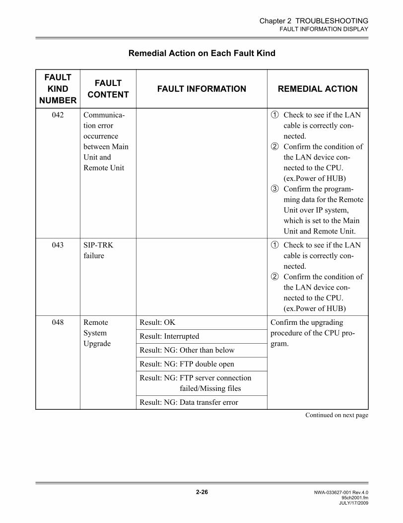
Chapter 2 TROUBLESHOOTING
2-26 NWA-033627-001 Rev.4.095ch2001.fm
FAULT INFORMATION DISPLAY
Remedial Action on Each Fault Kind
FAULT KIND
NUMBER
FAULT CONTENT FAULT INFORMATION REMEDIAL ACTION
042 Communica-tion error occurrence between Main Unit and Remote Unit
Check to see if the LAN cable is correctly con-nected.Confirm the condition of the LAN device con-nected to the CPU.(ex.Power of HUB)Confirm the program-ming data for the Remote Unit over IP system, which is set to the Main Unit and Remote Unit.
043 SIP-TRK failure
Check to see if the LAN cable is correctly con-nected.Confirm the condition of the LAN device con-nected to the CPU.(ex.Power of HUB)
048 Remote System Upgrade
Result: OK Confirm the upgrading procedure of the CPU pro-gram.
Result: Interrupted
Result: NG: Other than below
Result: NG: FTP double open
Result: NG: FTP server connectionfailed/Missing files
Result: NG: Data transfer errorContinued on next page
1
2
3
1
2
JULY/17/2009
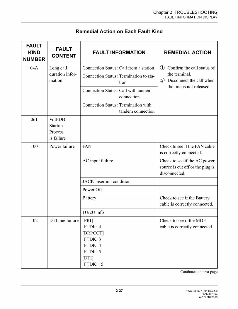
Chapter 2 TROUBLESHOOTING
2-27 NWA-033627-001 Rev.4.095ch2001.fm
FAULT INFORMATION DISPLAY
Remedial Action on Each Fault Kind
FAULT KIND
NUMBER
FAULT CONTENT FAULT INFORMATION REMEDIAL ACTION
04A Long call duration infor-mation
Connection Status: Call from a station Confirm the call status of the terminal.Disconnect the call when the line is not released.
Connection Status: Termination to sta-tion
Connection Status: Call with tandem connection
Connection Status: Termination with tandem connection
061 VoIPDB Startup Process is failure
100 Power failure FAN Check to see if the FAN cable is correctly connected.
AC input failure Check to see if the AC power source is cut off or the plug is disconnected.
JACK insertion condition
Power Off
Battery Check to see if the Battery cable is correctly connected.
1U/2U info
102 DTI line failure [PRI]FTDK: 4
[BRI/CCT]FTDK: 3FTDK: 4FTDK: 5
[DTI]FTDK: 15
Check to see if the MDF cable is correctly connected.
Continued on next page
1
2
APRIL/16/2010
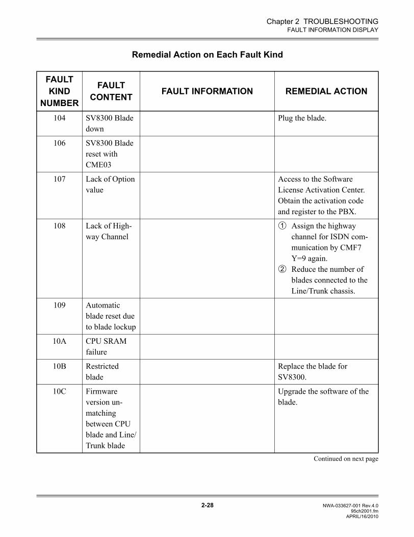
Chapter 2 TROUBLESHOOTING
2-28 NWA-033627-001 Rev.4.095ch2001.fm
FAULT INFORMATION DISPLAY
Remedial Action on Each Fault Kind
FAULT KIND
NUMBER
FAULT CONTENT FAULT INFORMATION REMEDIAL ACTION
104 SV8300 Blade down
Plug the blade.
106 SV8300 Blade reset with CME03
107 Lack of Option value
Access to the Software License Activation Center.Obtain the activation code and register to the PBX.
108 Lack of High-way Channel
Assign the highway channel for ISDN com-munication by CMF7 Y=9 again.Reduce the number of blades connected to the Line/Trunk chassis.
109 Automatic blade reset due to blade lockup
10A CPU SRAM failure
10B Restricted blade
Replace the blade for SV8300.
10C Firmware version un-matching between CPU blade and Line/Trunk blade
Upgrade the software of the blade.
Continued on next page
1
2
APRIL/16/2010
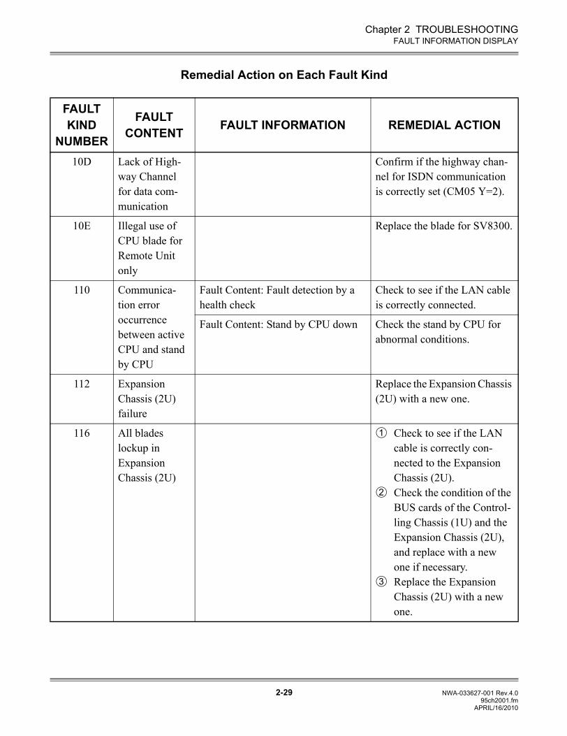
Chapter 2 TROUBLESHOOTING
2-29 NWA-033627-001 Rev.4.095ch2001.fm
FAULT INFORMATION DISPLAY
Remedial Action on Each Fault Kind
FAULT KIND
NUMBER
FAULT CONTENT FAULT INFORMATION REMEDIAL ACTION
10D Lack of High-way Channel for data com-munication
Confirm if the highway chan-nel for ISDN communication is correctly set (CM05 Y=2).
10E Illegal use of CPU blade for Remote Unit only
Replace the blade for SV8300.
110 Communica-tion error occurrence between active CPU and stand by CPU
Fault Content: Fault detection by a health check
Check to see if the LAN cable is correctly connected.
Fault Content: Stand by CPU down Check the stand by CPU for abnormal conditions.
112 Expansion Chassis (2U) failure
Replace the Expansion Chassis (2U) with a new one.
116 All blades lockup in Expansion Chassis (2U)
Check to see if the LAN cable is correctly con-nected to the Expansion Chassis (2U).Check the condition of the BUS cards of the Control-ling Chassis (1U) and the Expansion Chassis (2U), and replace with a new one if necessary.Replace the Expansion Chassis (2U) with a new one.
1
2
3
APRIL/16/2010
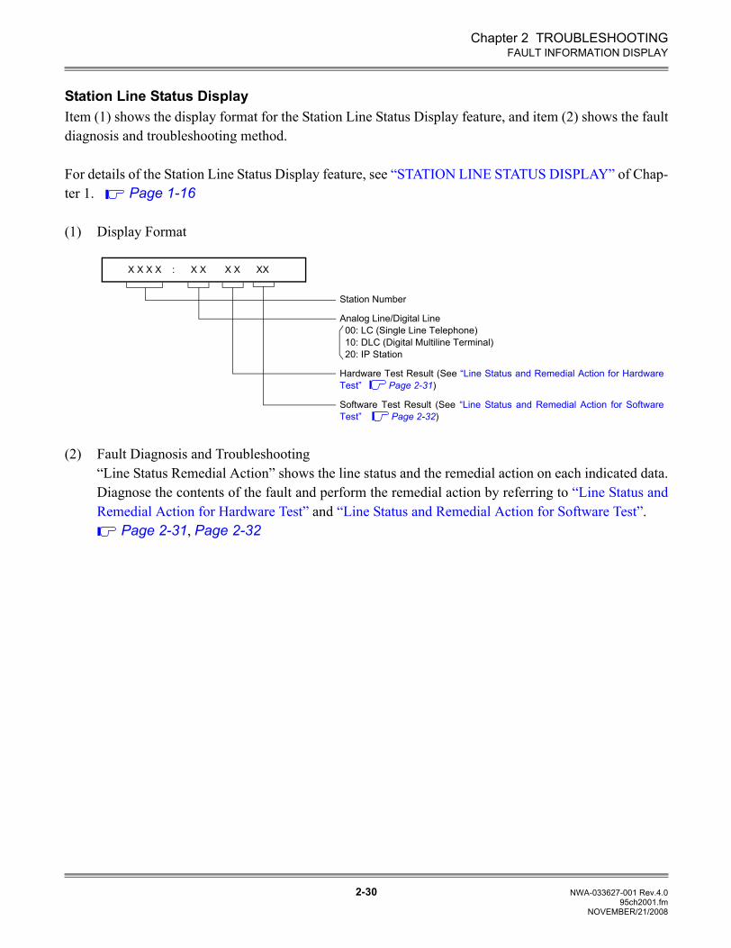
Chapter 2 TROUBLESHOOTING
2-30 NWA-033627-001 Rev.4.095ch2001.fm
FAULT INFORMATION DISPLAY
Station Line Status DisplayItem (1) shows the display format for the Station Line Status Display feature, and item (2) shows the faultdiagnosis and troubleshooting method.
For details of the Station Line Status Display feature, see “STATION LINE STATUS DISPLAY” of Chap-ter 1. Page 1-16
(1) Display Format
(2) Fault Diagnosis and Troubleshooting“Line Status Remedial Action” shows the line status and the remedial action on each indicated data.Diagnose the contents of the fault and perform the remedial action by referring to “Line Status andRemedial Action for Hardware Test” and “Line Status and Remedial Action for Software Test”.
Page 2-31, Page 2-32
X X X X : X X X X XX
Station Number
Analog Line/Digital Line00: LC (Single Line Telephone)10: DLC (Digital Multiline Terminal)20: IP Station
Hardware Test Result (See “Line Status and Remedial Action for HardwareTest” Page 2-31)
Software Test Result (See “Line Status and Remedial Action for SoftwareTest” Page 2-32)
NOVEMBER/21/2008
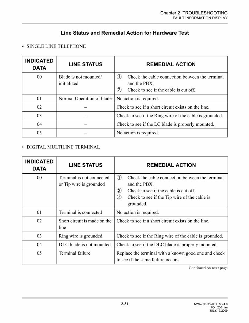
Chapter 2 TROUBLESHOOTING
2-31 NWA-033627-001 Rev.4.095ch2001.fm
FAULT INFORMATION DISPLAY
Line Status and Remedial Action for Hardware Test
• SINGLE LINE TELEPHONE
• DIGITAL MULTILINE TERMINAL
Continued on next page
INDICATED DATA LINE STATUS REMEDIAL ACTION
00 Blade is not mounted/initialized
Check the cable connection between the terminal and the PBX. Check to see if the cable is cut off.
01 Normal Operation of blade No action is required.
02 – Check to see if a short circuit exists on the line.
03 – Check to see if the Ring wire of the cable is grounded.
04 – Check to see if the LC blade is properly mounted.
05 – No action is required.
INDICATED DATA LINE STATUS REMEDIAL ACTION
00 Terminal is not connected or Tip wire is grounded
Check the cable connection between the terminal and the PBX.Check to see if the cable is cut off.Check to see if the Tip wire of the cable is grounded.
01 Terminal is connected No action is required.
02 Short circuit is made on the line
Check to see if a short circuit exists on the line.
03 Ring wire is grounded Check to see if the Ring wire of the cable is grounded.
04 DLC blade is not mounted Check to see if the DLC blade is properly mounted.
05 Terminal failure Replace the terminal with a known good one and check to see if the same failure occurs.
1
2
1
23
JULY/17/2009
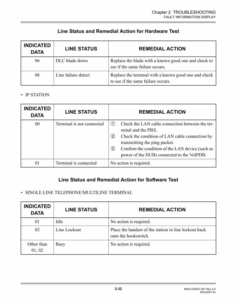
Chapter 2 TROUBLESHOOTING
2-32 NWA-033627-001 Rev.4.095ch2001.fm
FAULT INFORMATION DISPLAY
Line Status and Remedial Action for Hardware Test
• IP STATION
Line Status and Remedial Action for Software Test
• SINGLE LINE TELEPHONE/MULTILINE TERMINAL
INDICATED DATA LINE STATUS REMEDIAL ACTION
06 DLC blade down Replace the blade with a known good one and check to see if the same failure occurs.
08 Line failure detect Replace the terminal with a known good one and check to see if the same failure occurs.
INDICATED DATA LINE STATUS REMEDIAL ACTION
00 Terminal is not connected Check the LAN cable connection between the ter-minal and the PBX. Check the condition of LAN cable connection by transmitting the ping packet. Confirm the condition of the LAN device (such as power of the HUB) connected to the VoIPDB.
01 Terminal is connected No action is required.
INDICATED DATA LINE STATUS REMEDIAL ACTION
01 Idle No action is required.
02 Line Lockout Place the handset of the station in line lockout back onto the hookswitch.
Other than 01, 02
Busy No action is required.
1
2
3
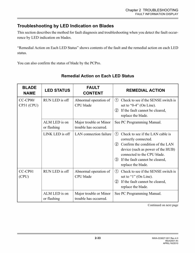
Chapter 2 TROUBLESHOOTING
2-33 NWA-033627-001 Rev.4.095ch2001.fm
FAULT INFORMATION DISPLAY
Troubleshooting by LED Indication on BladesThis section describes the method for fault diagnosis and troubleshooting when you detect the fault occur-rence by LED indication on blades.
“Remedial Action on Each LED Status” shows contents of the fault and the remedial action on each LEDstatus.
You can also confirm the status of blade by the PCPro.
Remedial Action on Each LED Status
BLADE NAME LED STATUS FAULT
CONTENT REMEDIAL ACTION
CC-CP00/CP31 (CPU)
RUN LED is off Abnormal operation of CPU blade
Check to see if the SENSE switch is set to “0-4” (On Line).If the fault cannot be cleared, replace the blade.
ALM LED is on or flashing
Major trouble or Minor trouble has occurred.
See PC Programming Manual.
LINK LED is off LAN connection failure Check to see if the LAN cable is correctly connected.Confirm the condition of the LAN device (such as power of the HUB) connected to the CPU blade.If the fault cannot be cleared, replace the blade.
CC-CP01 (CPU)
RUN LED is off Abnormal operation of CPU blade
Check to see if the SENSE switch is set to “1” (On Line).If the fault cannot be cleared, replace the blade.
ALM LED is on or flashing
Major trouble or Minor trouble has occurred.
See PC Programming Manual.
Continued on next page
1
2
1
2
3
1
2
APRIL/16/2010
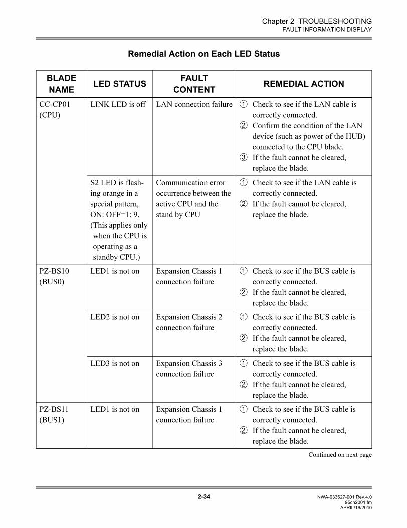
Chapter 2 TROUBLESHOOTING
2-34 NWA-033627-001 Rev.4.095ch2001.fm
FAULT INFORMATION DISPLAY
Remedial Action on Each LED Status
BLADE NAME LED STATUS FAULT
CONTENT REMEDIAL ACTION
CC-CP01 (CPU)
LINK LED is off LAN connection failure Check to see if the LAN cable is correctly connected.Confirm the condition of the LAN device (such as power of the HUB) connected to the CPU blade.If the fault cannot be cleared, replace the blade.
S2 LED is flash-ing orange in a special pattern, ON: OFF=1: 9.(This applies only when the CPU is operating as a standby CPU.)
Communication error occurrence between the active CPU and the stand by CPU
Check to see if the LAN cable is correctly connected.If the fault cannot be cleared, replace the blade.
PZ-BS10 (BUS0)
LED1 is not on Expansion Chassis 1 connection failure
Check to see if the BUS cable is correctly connected.If the fault cannot be cleared, replace the blade.
LED2 is not on Expansion Chassis 2 connection failure
Check to see if the BUS cable is correctly connected.If the fault cannot be cleared, replace the blade.
LED3 is not on Expansion Chassis 3 connection failure
Check to see if the BUS cable is correctly connected.If the fault cannot be cleared, replace the blade.
PZ-BS11 (BUS1)
LED1 is not on Expansion Chassis 1 connection failure
Check to see if the BUS cable is correctly connected.If the fault cannot be cleared, replace the blade.
Continued on next page
1
2
3
1
2
1
2
1
2
1
2
1
2
APRIL/16/2010
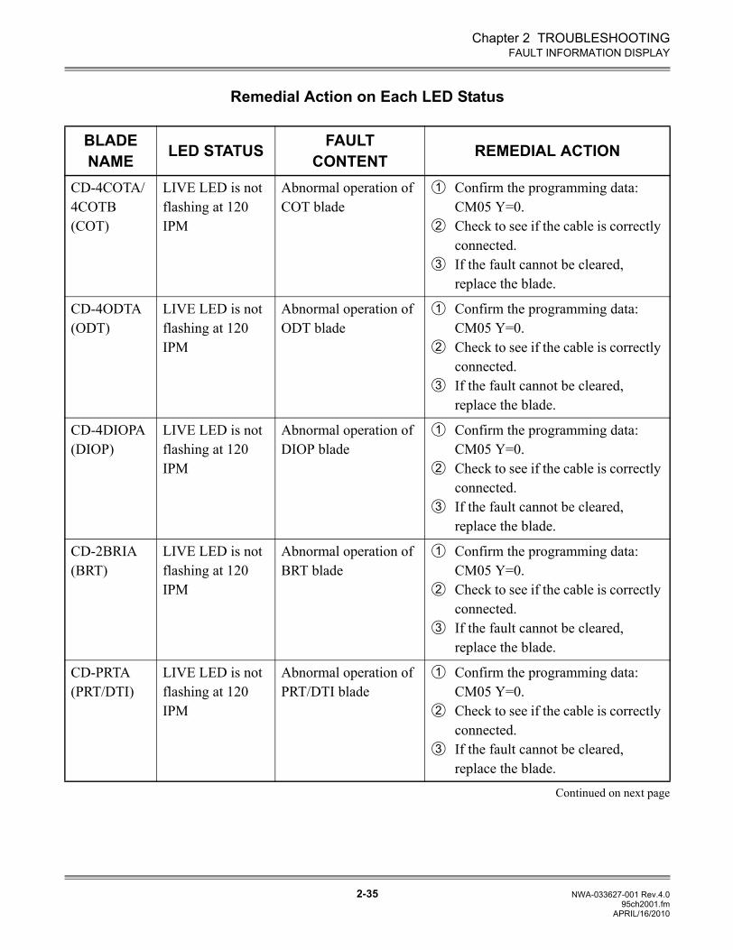
Chapter 2 TROUBLESHOOTING
2-35 NWA-033627-001 Rev.4.095ch2001.fm
FAULT INFORMATION DISPLAY
Remedial Action on Each LED Status
BLADE NAME LED STATUS FAULT
CONTENT REMEDIAL ACTION
CD-4COTA/4COTB (COT)
LIVE LED is not flashing at 120 IPM
Abnormal operation of COT blade
Confirm the programming data: CM05 Y=0.Check to see if the cable is correctly connected.If the fault cannot be cleared, replace the blade.
CD-4ODTA (ODT)
LIVE LED is not flashing at 120 IPM
Abnormal operation of ODT blade
Confirm the programming data: CM05 Y=0.Check to see if the cable is correctly connected.If the fault cannot be cleared, replace the blade.
CD-4DIOPA (DIOP)
LIVE LED is not flashing at 120 IPM
Abnormal operation of DIOP blade
Confirm the programming data: CM05 Y=0.Check to see if the cable is correctly connected.If the fault cannot be cleared, replace the blade.
CD-2BRIA (BRT)
LIVE LED is not flashing at 120 IPM
Abnormal operation of BRT blade
Confirm the programming data: CM05 Y=0.Check to see if the cable is correctly connected.If the fault cannot be cleared, replace the blade.
CD-PRTA (PRT/DTI)
LIVE LED is not flashing at 120 IPM
Abnormal operation of PRT/DTI blade
Confirm the programming data: CM05 Y=0.Check to see if the cable is correctly connected.If the fault cannot be cleared, replace the blade.
Continued on next page
1
2
3
1
2
3
1
2
3
1
2
3
1
2
3
APRIL/16/2010
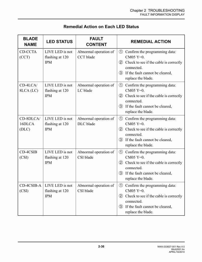
Chapter 2 TROUBLESHOOTING
2-36 NWA-033627-001 Rev.4.095ch2001.fm
FAULT INFORMATION DISPLAY
Remedial Action on Each LED Status
BLADE NAME LED STATUS FAULT
CONTENT REMEDIAL ACTION
CD-CCTA (CCT)
LIVE LED is not flashing at 120 IPM
Abnormal operation of CCT blade
Confirm the programming data: CM05 Y=0.Check to see if the cable is correctly connected.If the fault cannot be cleared, replace the blade.
CD-4LCA/8LCA (LC)
LIVE LED is not flashing at 120 IPM
Abnormal operation of LC blade
Confirm the programming data: CM05 Y=0.Check to see if the cable is correctly connected.If the fault cannot be cleared, replace the blade.
CD-8DLCA/16DLCA (DLC)
LIVE LED is not flashing at 120 IPM
Abnormal operation of DLC blade
Confirm the programming data: CM05 Y=0.Check to see if the cable is correctly connected.If the fault cannot be cleared, replace the blade.
CD-4CSIB (CSI)
LIVE LED is not flashing at 120 IPM
Abnormal operation of CSI blade
Confirm the programming data: CM05 Y=0.Check to see if the cable is correctly connected.If the fault cannot be cleared, replace the blade.
CD-4CSIB-A (CSI)
LIVE LED is not flashing at 120 IPM
Abnormal operation of CSI blade
Confirm the programming data: CM05 Y=0.Check to see if the cable is correctly connected.If the fault cannot be cleared, replace the blade.
1
2
3
1
2
3
1
2
3
1
2
3
1
2
3
APRIL/16/2010
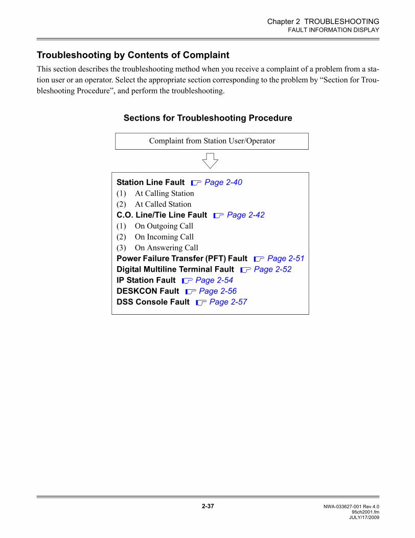
Chapter 2 TROUBLESHOOTING
2-37 NWA-033627-001 Rev.4.095ch2001.fm
FAULT INFORMATION DISPLAY
Troubleshooting by Contents of ComplaintThis section describes the troubleshooting method when you receive a complaint of a problem from a sta-tion user or an operator. Select the appropriate section corresponding to the problem by “Section for Trou-bleshooting Procedure”, and perform the troubleshooting.
Sections for Troubleshooting Procedure
Complaint from Station User/Operator
Station Line Fault Page 2-40(1) At Calling Station(2) At Called StationC.O. Line/Tie Line Fault Page 2-42(1) On Outgoing Call(2) On Incoming Call(3) On Answering CallPower Failure Transfer (PFT) Fault Page 2-51Digital Multiline Terminal Fault Page 2-52IP Station Fault Page 2-54 DESKCON Fault Page 2-56DSS Console Fault Page 2-57
JULY/17/2009
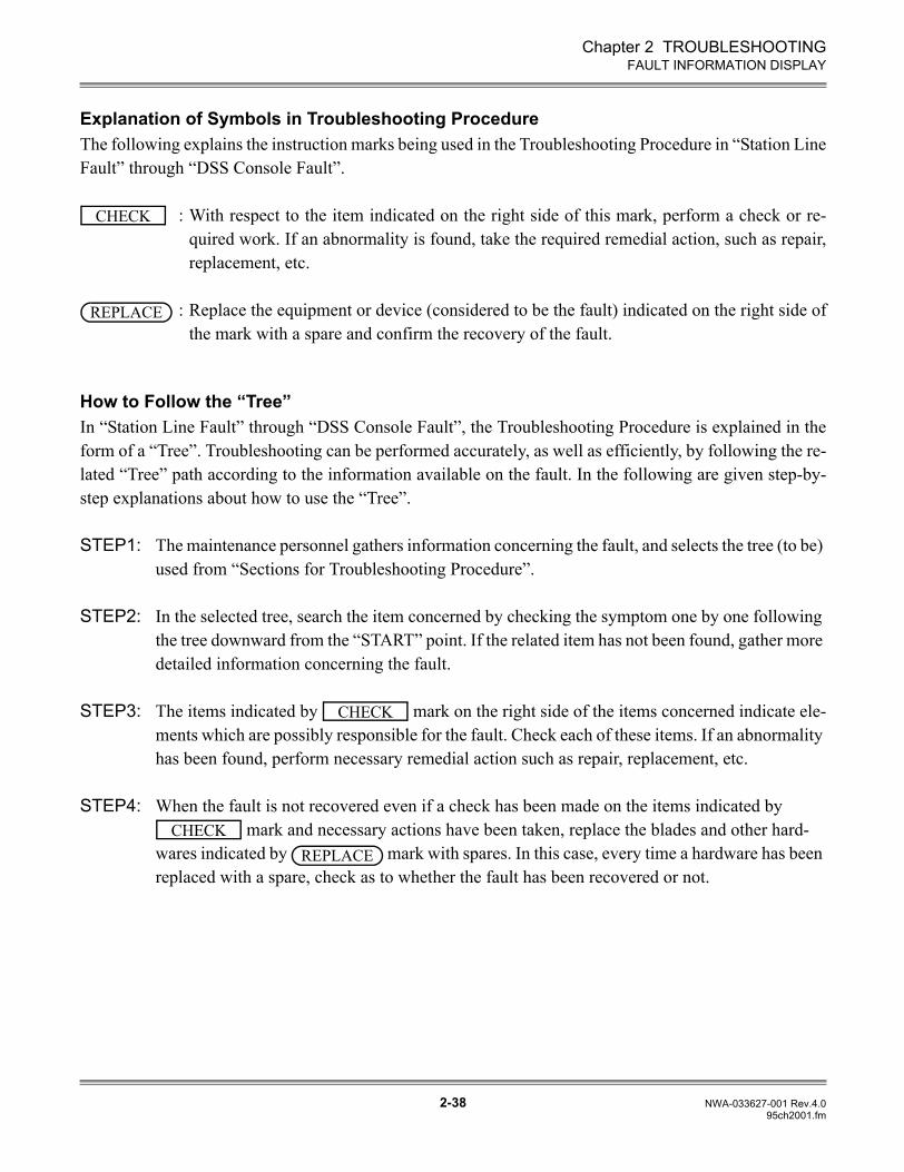
Chapter 2 TROUBLESHOOTING
2-38 NWA-033627-001 Rev.4.095ch2001.fm
FAULT INFORMATION DISPLAY
Explanation of Symbols in Troubleshooting ProcedureThe following explains the instruction marks being used in the Troubleshooting Procedure in “Station LineFault” through “DSS Console Fault”.
: With respect to the item indicated on the right side of this mark, perform a check or re-quired work. If an abnormality is found, take the required remedial action, such as repair,replacement, etc.
: Replace the equipment or device (considered to be the fault) indicated on the right side ofthe mark with a spare and confirm the recovery of the fault.
How to Follow the “Tree”In “Station Line Fault” through “DSS Console Fault”, the Troubleshooting Procedure is explained in theform of a “Tree”. Troubleshooting can be performed accurately, as well as efficiently, by following the re-lated “Tree” path according to the information available on the fault. In the following are given step-by-step explanations about how to use the “Tree”.
STEP1: The maintenance personnel gathers information concerning the fault, and selects the tree (to be) used from “Sections for Troubleshooting Procedure”.
STEP2: In the selected tree, search the item concerned by checking the symptom one by one following the tree downward from the “START” point. If the related item has not been found, gather more detailed information concerning the fault.
STEP3: The items indicated by mark on the right side of the items concerned indicate ele-ments which are possibly responsible for the fault. Check each of these items. If an abnormality has been found, perform necessary remedial action such as repair, replacement, etc.
STEP4: When the fault is not recovered even if a check has been made on the items indicated by mark and necessary actions have been taken, replace the blades and other hard-
wares indicated by mark with spares. In this case, every time a hardware has been replaced with a spare, check as to whether the fault has been recovered or not.
CHECK
REPLACE
CHECK
CHECKREPLACE
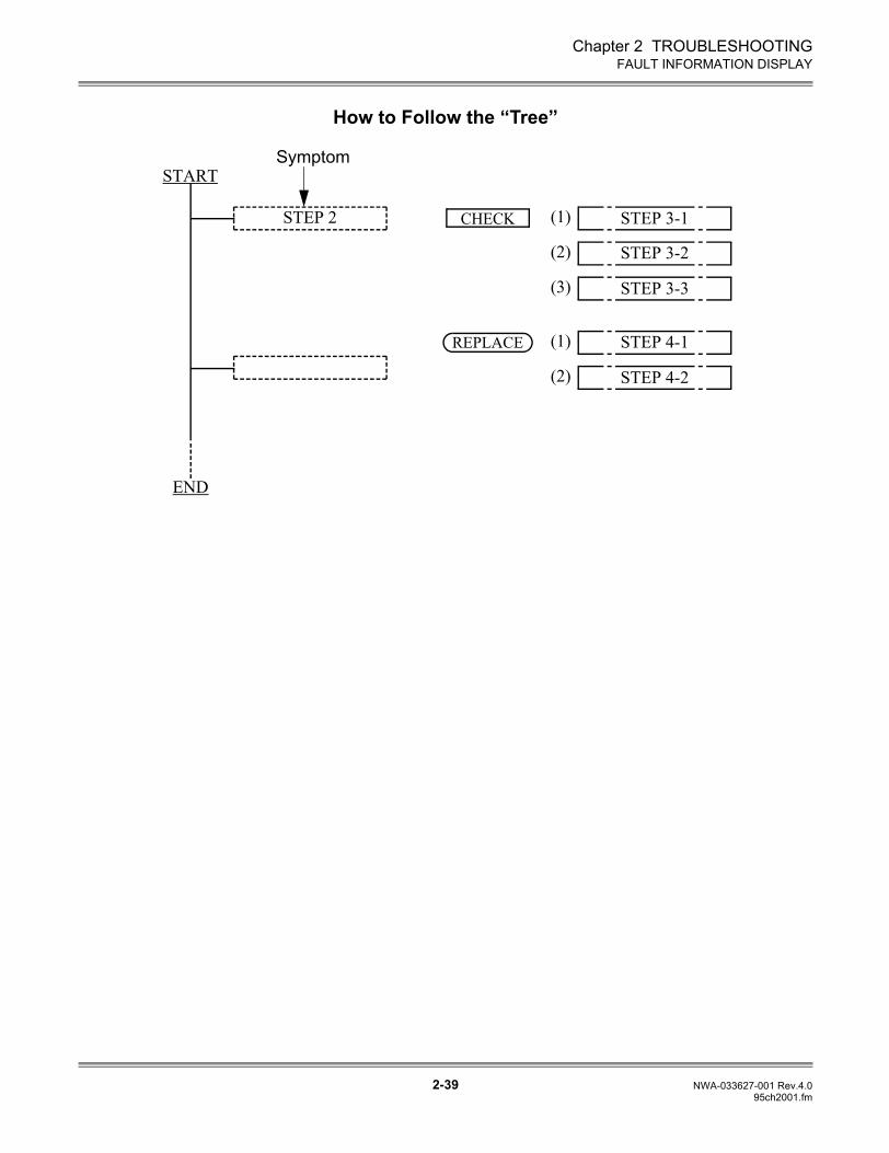
Chapter 2 TROUBLESHOOTING
2-39 NWA-033627-001 Rev.4.095ch2001.fm
FAULT INFORMATION DISPLAY
How to Follow the “Tree”
START
END
Symptom
STEP 2 STEP 3-1(1)
STEP 3-2(2)
STEP 4-1(1)
STEP 3-3(3)
STEP 4-2(2)
CHECK
REPLACE
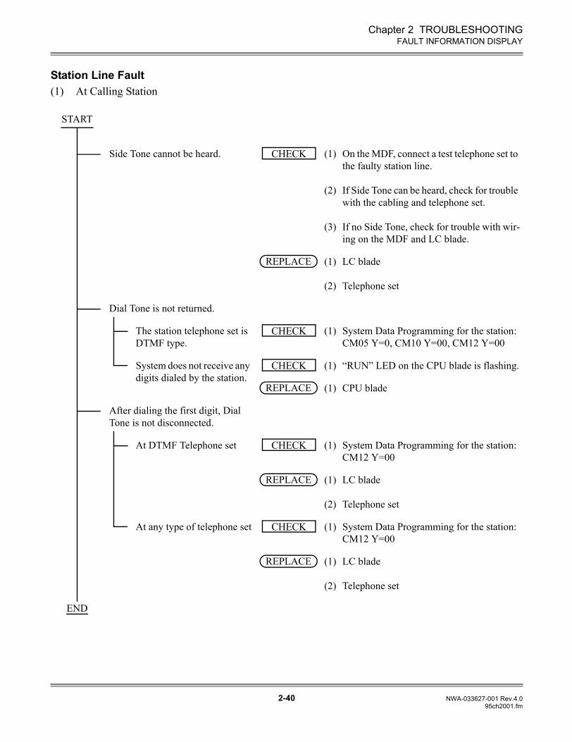
Chapter 2 TROUBLESHOOTING
2-40 NWA-033627-001 Rev.4.095ch2001.fm
FAULT INFORMATION DISPLAY
Station Line Fault(1) At Calling Station
Side Tone cannot be heard. (1)
(2)
(3)
On the MDF, connect a test telephone set to the faulty station line.
If Side Tone can be heard, check for trouble with the cabling and telephone set.
If no Side Tone, check for trouble with wir-ing on the MDF and LC blade.
(1)
(2)
LC blade
Telephone set
Dial Tone is not returned.
The station telephone set is DTMF type.
(1) System Data Programming for the station: CM05 Y=0, CM10 Y=00, CM12 Y=00
System does not receive any digits dialed by the station.
(1) “RUN” LED on the CPU blade is flashing.
(1) CPU blade
After dialing the first digit, Dial Tone is not disconnected.
At DTMF Telephone set (1) System Data Programming for the station: CM12 Y=00
(1)
(2)
LC blade
Telephone set
At any type of telephone set (1) System Data Programming for the station: CM12 Y=00
(1)
(2)
LC blade
Telephone set
START
CHECK
REPLACE
CHECK
CHECK
REPLACE
CHECK
REPLACE
CHECK
REPLACE
END
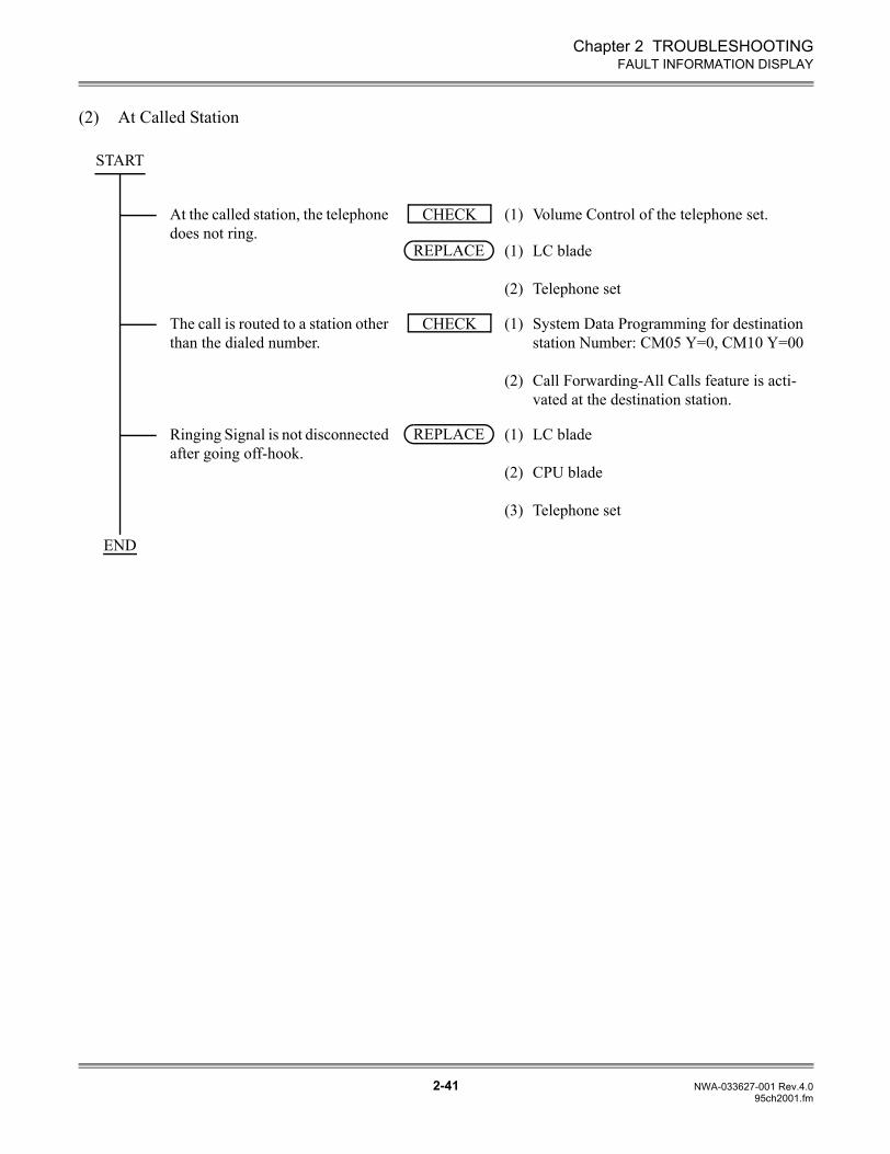
Chapter 2 TROUBLESHOOTING
2-41 NWA-033627-001 Rev.4.095ch2001.fm
FAULT INFORMATION DISPLAY
(2) At Called Station
At the called station, the telephone does not ring.
(1) Volume Control of the telephone set.
(1)
(2)
LC blade
Telephone set
The call is routed to a station other than the dialed number.
(1)
(2)
System Data Programming for destination station Number: CM05 Y=0, CM10 Y=00
Call Forwarding-All Calls feature is acti-vated at the destination station.
Ringing Signal is not disconnected after going off-hook.
(1)
(2)
(3)
LC blade
CPU blade
Telephone set
START
CHECK
REPLACE
CHECK
REPLACE
END
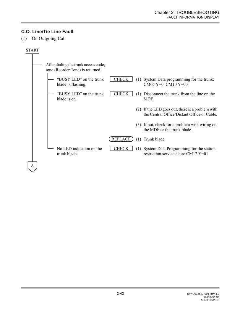
Chapter 2 TROUBLESHOOTING
2-42 NWA-033627-001 Rev.4.095ch2001.fm
FAULT INFORMATION DISPLAY
C.O. Line/Tie Line Fault(1) On Outgoing Call
After dialing the trunk access code, tone (Reorder Tone) is returned.
“BUSY LED” on the trunk blade is flashing.
(1) System Data programming for the trunk: CM05 Y=0, CM10 Y=00
“BUSY LED” on the trunk blade is on.
(1)
(2)
(3)
Disconnect the trunk from the line on the MDF.
If the LED goes out, there is a problem with the Central Office/Distant Office or Cable.
If not, check for a problem with wiring on the MDF or the trunk blade.
(1) Trunk blade
No LED indication on the trunk blade.
(1) System Data Programming for the station restriction service class: CM12 Y=01
START
CHECK
CHECK
REPLACE
CHECK
A
APRIL/16/2010
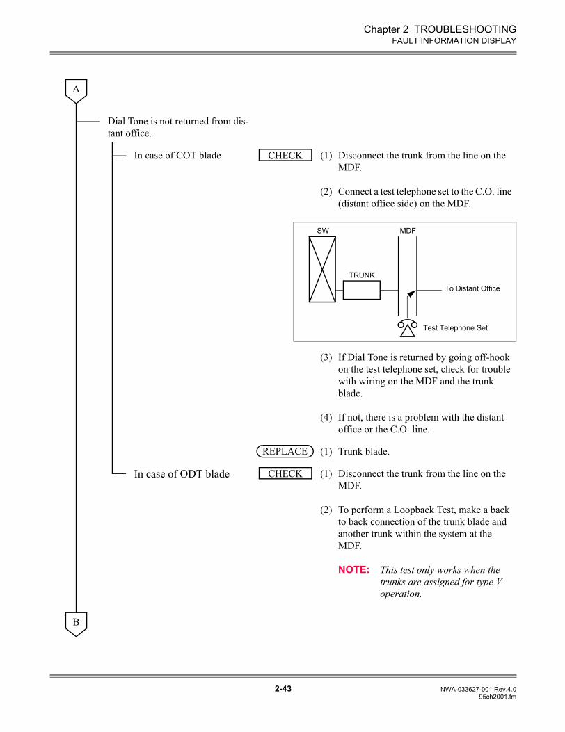
Chapter 2 TROUBLESHOOTING
2-43 NWA-033627-001 Rev.4.095ch2001.fm
FAULT INFORMATION DISPLAY
Dial Tone is not returned from dis-tant office.
In case of COT blade (1)
(2)
Disconnect the trunk from the line on the MDF.
Connect a test telephone set to the C.O. line (distant office side) on the MDF.
(3)
(4)
If Dial Tone is returned by going off-hook on the test telephone set, check for trouble with wiring on the MDF and the trunk blade.
If not, there is a problem with the distant office or the C.O. line.
(1) Trunk blade.
In case of ODT blade (1)
(2)
Disconnect the trunk from the line on the MDF.
To perform a Loopback Test, make a back to back connection of the trunk blade and another trunk within the system at the MDF.
NOTE: This test only works when the trunks are assigned for type V operation.
A
CHECK
SW MDF
TRUNK
To Distant Office
Test Telephone Set
REPLACE
CHECK
B
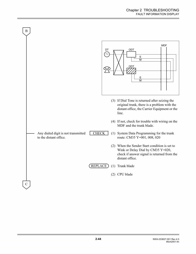
Chapter 2 TROUBLESHOOTING
2-44 NWA-033627-001 Rev.4.095ch2001.fm
FAULT INFORMATION DISPLAY
(3)
(4)
If Dial Tone is returned after seizing the original trunk, there is a problem with the distant office, the Carrier Equipment or the line.
If not, check for trouble with wiring on the MDF and the trunk blade.
Any dialed digit is not transmitted to the distant office.
(1)
(2)
System Data Programming for the trunk route: CM35 Y=001, 008, 020
When the Sender Start condition is set to Wink or Delay Dial by CM35 Y=020, check if answer signal is returned from the distant office.
(1)
(2)
Trunk blade
CPU blade
B
~
MDFDT ODT
ODT
EM
EM
CHECK
REPLACE
C
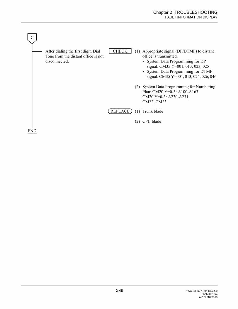
Chapter 2 TROUBLESHOOTING
2-45 NWA-033627-001 Rev.4.095ch2001.fm
FAULT INFORMATION DISPLAY
After dialing the first digit, Dial Tone from the distant office is not disconnected.
(1)
(2)
Appropriate signal (DP/DTMF) to distant office is transmitted. • System Data Programming for DP
signal: CM35 Y=001, 013, 023, 025• System Data Programming for DTMF
signal: CM35 Y=001, 013, 024, 026, 046
System Data Programming for Numbering Plan: CM20 Y=0-3: A100-A163, CM20 Y=0-3: A230-A231, CM22, CM23
(1)
(2)
Trunk blade
CPU blade
C
CHECK
REPLACE
END
APRIL/16/2010
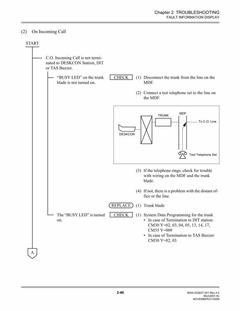
Chapter 2 TROUBLESHOOTING
2-46 NWA-033627-001 Rev.4.095ch2001.fm
FAULT INFORMATION DISPLAY
(2) On Incoming Call
C.O. Incoming Call is not termi-nated to DESKCON Station, DIT or TAS Buzzer.
“BUSY LED” on the trunk blade is not turned on.
(1)
(2)
Disconnect the trunk from the line on the MDF.
Connect a test telephone set to the line on the MDF.
(3)
(4)
If the telephone rings, check for trouble with wiring on the MDF and the trunk blade.
If not, there is a problem with the distant of-fice or the line.
(1) Trunk blade
The “BUSY LED” is turned on.
(1) System Data Programming for the trunk • In case of Termination to DIT station:
CM30 Y=02, 03, 04, 05, 13, 14, 17, CM35 Y=009
• In case of Termination to TAS Buzzer: CM30 Y=02, 03
START
CHECK
MDFTRUNK
To C.O. Line
Test Telephone Set
DESKCON
REPLACE
CHECK
A
NOVEMBER/21/2008
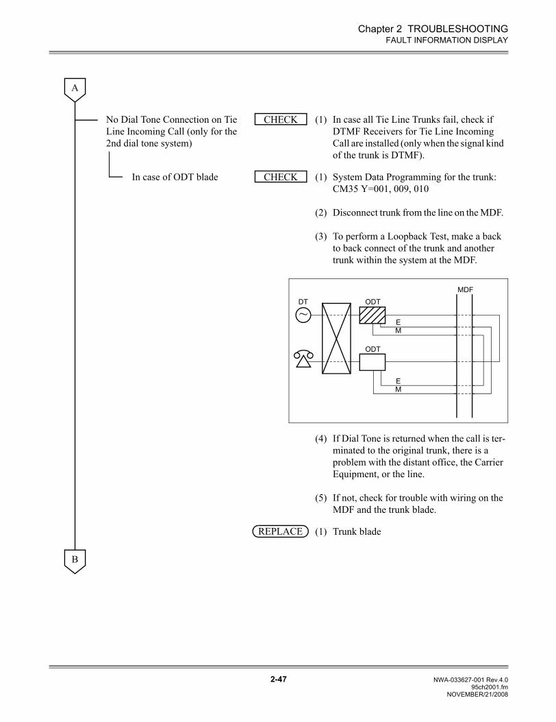
Chapter 2 TROUBLESHOOTING
2-47 NWA-033627-001 Rev.4.095ch2001.fm
FAULT INFORMATION DISPLAY
No Dial Tone Connection on Tie Line Incoming Call (only for the 2nd dial tone system)
(1) In case all Tie Line Trunks fail, check if DTMF Receivers for Tie Line Incoming Call are installed (only when the signal kind of the trunk is DTMF).
In case of ODT blade (1)
(2)
(3)
System Data Programming for the trunk: CM35 Y=001, 009, 010
Disconnect trunk from the line on the MDF.
To perform a Loopback Test, make a back to back connect of the trunk and another trunk within the system at the MDF.
(4)
(5)
If Dial Tone is returned when the call is ter-minated to the original trunk, there is a problem with the distant office, the Carrier Equipment, or the line.
If not, check for trouble with wiring on the MDF and the trunk blade.
(1) Trunk blade
A
CHECK
CHECK
~
MDFDT ODT
ODT
EM
EM
REPLACE
B
NOVEMBER/21/2008
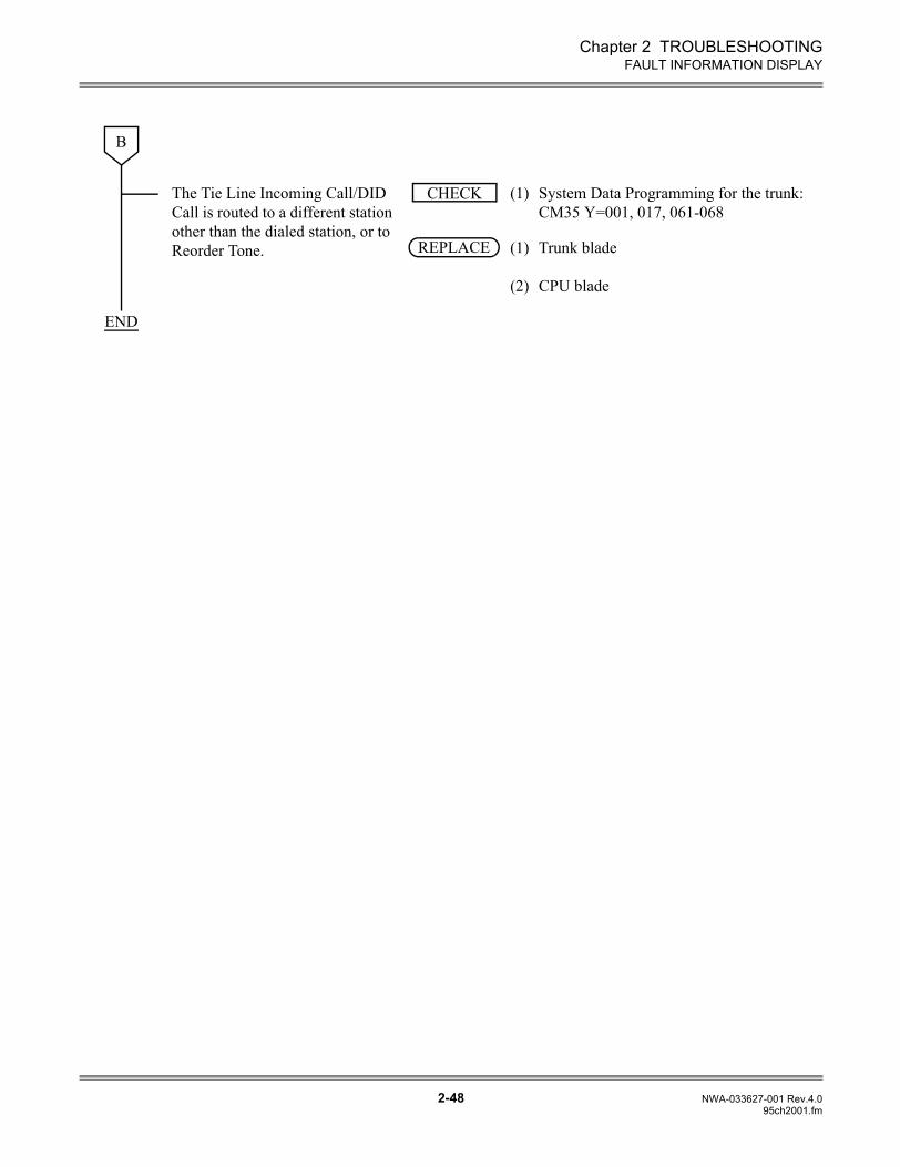
Chapter 2 TROUBLESHOOTING
2-48 NWA-033627-001 Rev.4.095ch2001.fm
FAULT INFORMATION DISPLAY
The Tie Line Incoming Call/DID Call is routed to a different station other than the dialed station, or to Reorder Tone.
(1) System Data Programming for the trunk: CM35 Y=001, 017, 061-068
(1)
(2)
Trunk blade
CPU blade
B
CHECK
REPLACE
END
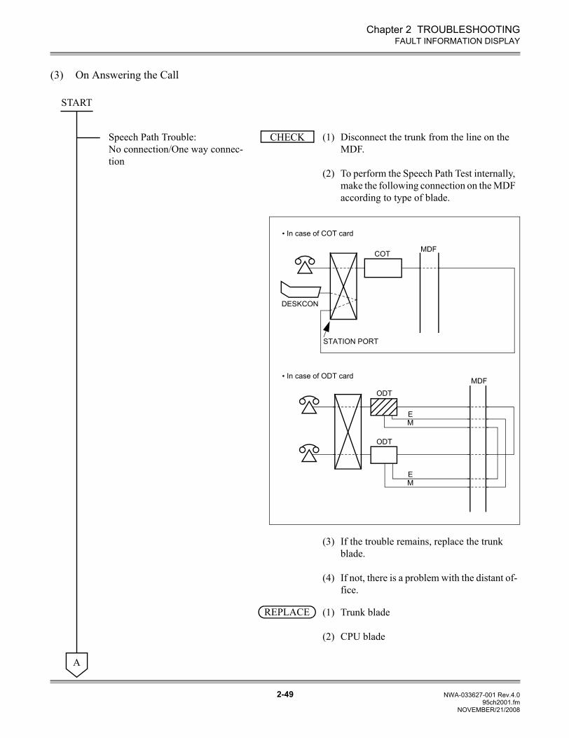
Chapter 2 TROUBLESHOOTING
2-49 NWA-033627-001 Rev.4.095ch2001.fm
FAULT INFORMATION DISPLAY
(3) On Answering the Call
Speech Path Trouble: No connection/One way connec-tion
(1)
(2)
Disconnect the trunk from the line on the MDF.
To perform the Speech Path Test internally, make the following connection on the MDF according to type of blade.
(3)
(4)
If the trouble remains, replace the trunk blade.
If not, there is a problem with the distant of-fice.
(1)
(2)
Trunk blade
CPU blade
START
CHECK
MDFODT
ODT
EM
EM
MDFCOT
DESKCON
STATION PORT
• In case of COT card
• In case of ODT card
REPLACE
A
NOVEMBER/21/2008
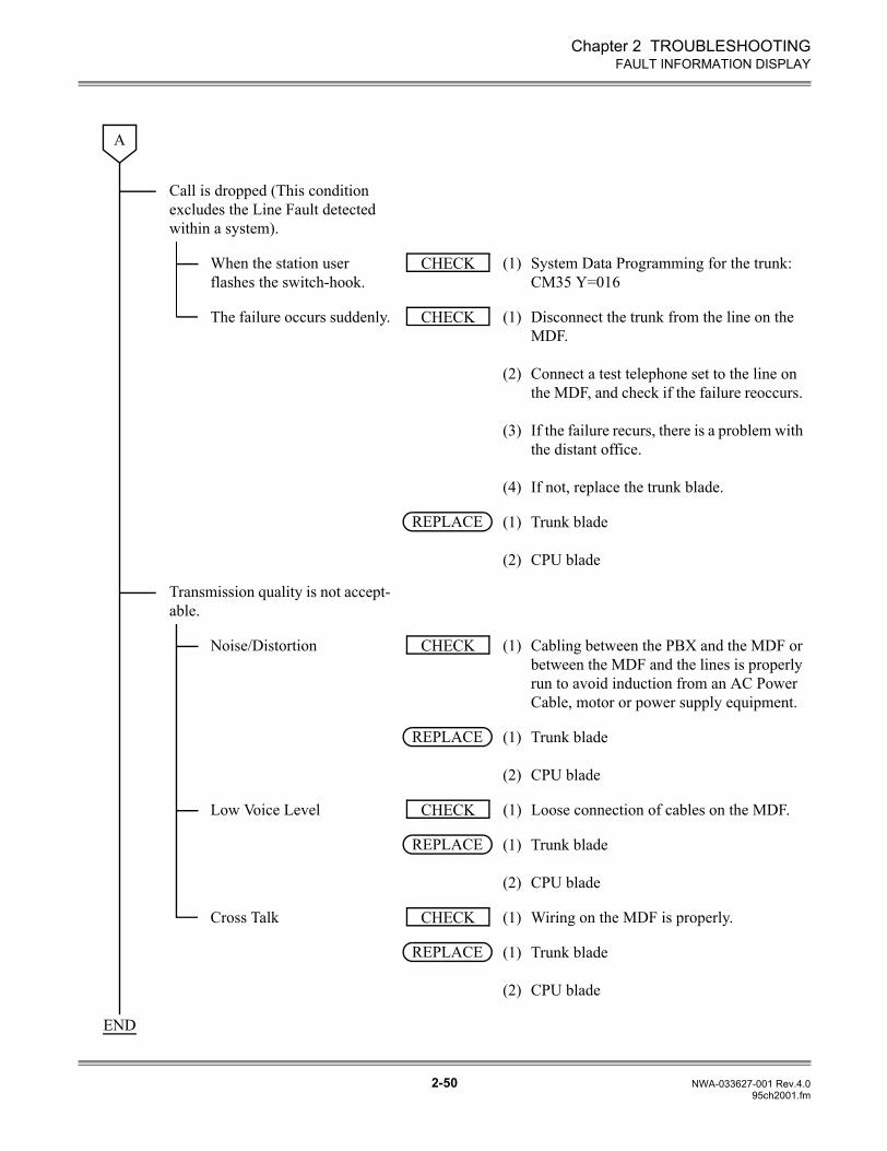
Chapter 2 TROUBLESHOOTING
2-50 NWA-033627-001 Rev.4.095ch2001.fm
FAULT INFORMATION DISPLAY
Call is dropped (This condition excludes the Line Fault detected within a system).
When the station user flashes the switch-hook.
(1) System Data Programming for the trunk: CM35 Y=016
The failure occurs suddenly. (1)
(2)
(3)
(4)
Disconnect the trunk from the line on the MDF.
Connect a test telephone set to the line on the MDF, and check if the failure reoccurs.
If the failure recurs, there is a problem with the distant office.
If not, replace the trunk blade.
(1)
(2)
Trunk blade
CPU blade
Transmission quality is not accept-able.
Noise/Distortion (1) Cabling between the PBX and the MDF or between the MDF and the lines is properly run to avoid induction from an AC Power Cable, motor or power supply equipment.
(1)
(2)
Trunk blade
CPU blade
Low Voice Level (1) Loose connection of cables on the MDF.
(1)
(2)
Trunk blade
CPU blade
Cross Talk (1) Wiring on the MDF is properly.
(1)
(2)
Trunk blade
CPU blade
A
CHECK
CHECK
REPLACE
CHECK
REPLACE
CHECK
REPLACE
CHECK
REPLACE
END
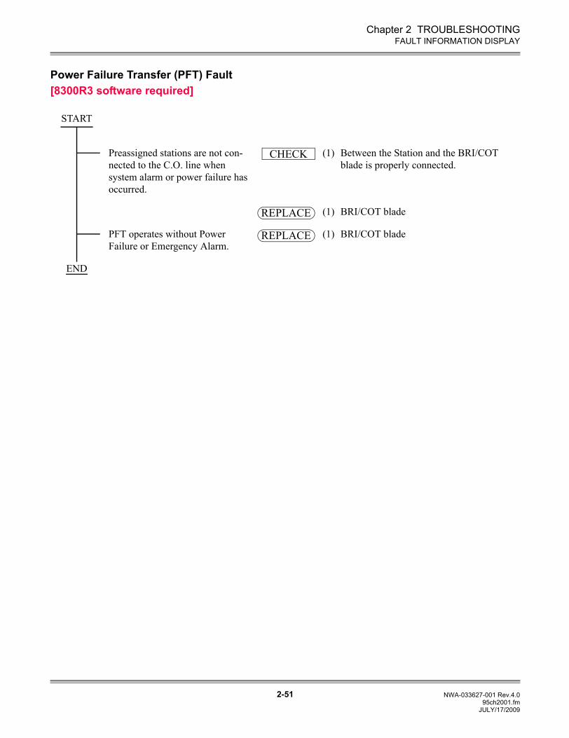
Chapter 2 TROUBLESHOOTING
2-51 NWA-033627-001 Rev.4.095ch2001.fm
FAULT INFORMATION DISPLAY
Power Failure Transfer (PFT) Fault[8300R3 software required]
Preassigned stations are not con-nected to the C.O. line when system alarm or power failure has occurred.
(1) Between the Station and the BRI/COT blade is properly connected.
(1) BRI/COT blade
PFT operates without Power Failure or Emergency Alarm.
(1) BRI/COT blade
START
CHECK
REPLACE
REPLACE
END
JULY/17/2009
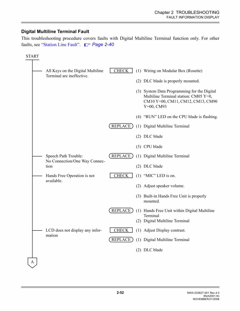
Chapter 2 TROUBLESHOOTING
2-52 NWA-033627-001 Rev.4.095ch2001.fm
FAULT INFORMATION DISPLAY
Digital Multiline Terminal FaultThis troubleshooting procedure covers faults with Digital Multiline Terminal function only. For otherfaults, see “Station Line Fault”. Page 2-40
All Keys on the Digital Multiline Terminal are ineffective.
(1)
(2)
(3)
(4)
Wiring on Modular Box (Rosette)
DLC blade is properly mounted.
System Data Programming for the Digital Multiline Terminal station: CM05 Y=0, CM10 Y=00, CM11, CM12, CM13, CM90 Y=00, CM93
“RUN” LED on the CPU blade is flashing.
(1)
(2)
(3)
Digital Multiline Terminal
DLC blade
CPU blade
Speech Path Trouble: No Connection/One Way Connec-tion
(1)
(2)
Digital Multiline Terminal
DLC blade
Hands Free Operation is not available.
(1)
(2)
(3)
“MIC” LED is on.
Adjust speaker volume.
Built-in Hands Free Unit is properly mounted.
(1)
(2)
Hands Free Unit within Digital Multiline Terminal Digital Multiline Terminal
LCD does not display any infor-mation
(1) Adjust Display contrast.
(1)
(2)
Digital Multiline Terminal
DLC blade
START
CHECK
REPLACE
REPLACE
CHECK
REPLACE
CHECK
REPLACE
A
NOVEMBER/21/2008
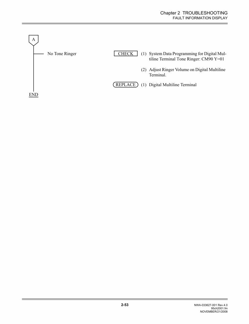
Chapter 2 TROUBLESHOOTING
2-53 NWA-033627-001 Rev.4.095ch2001.fm
FAULT INFORMATION DISPLAY
No Tone Ringer (1)
(2)
System Data Programming for Digital Mul-tiline Terminal Tone Ringer: CM90 Y=01
Adjust Ringer Volume on Digital Multiline Terminal.
(1) Digital Multiline Terminal
A
CHECK
REPLACE
END
NOVEMBER/21/2008
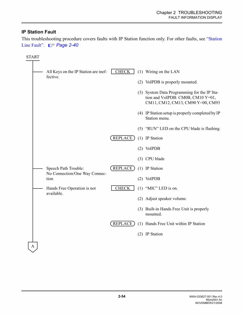
Chapter 2 TROUBLESHOOTING
2-54 NWA-033627-001 Rev.4.095ch2001.fm
FAULT INFORMATION DISPLAY
IP Station FaultThis troubleshooting procedure covers faults with IP Station function only. For other faults, see “StationLine Fault”. Page 2-40
All Keys on the IP Station are inef-fective.
(1)
(2)
(3)
(4)
(5)
Wiring on the LAN
VoIPDB is properly mounted.
System Data Programming for the IP Sta-tion and VoIPDB: CM0B, CM10 Y=01, CM11, CM12, CM13, CM90 Y=00, CM93
IP Station setup is properly completed by IP Station menu.
“RUN” LED on the CPU blade is flashing.
(1)
(2)
(3)
IP Station
VoIPDB
CPU blade
Speech Path Trouble: No Connection/One Way Connec-tion
(1)
(2)
IP Station
VoIPDB
Hands Free Operation is not available.
(1)
(2)
(3)
“MIC” LED is on.
Adjust speaker volume.
Built-in Hands Free Unit is properly mounted.
(1)
(2)
Hands Free Unit within IP Station
IP Station
START
CHECK
REPLACE
REPLACE
CHECK
REPLACE
A
NOVEMBER/21/2008
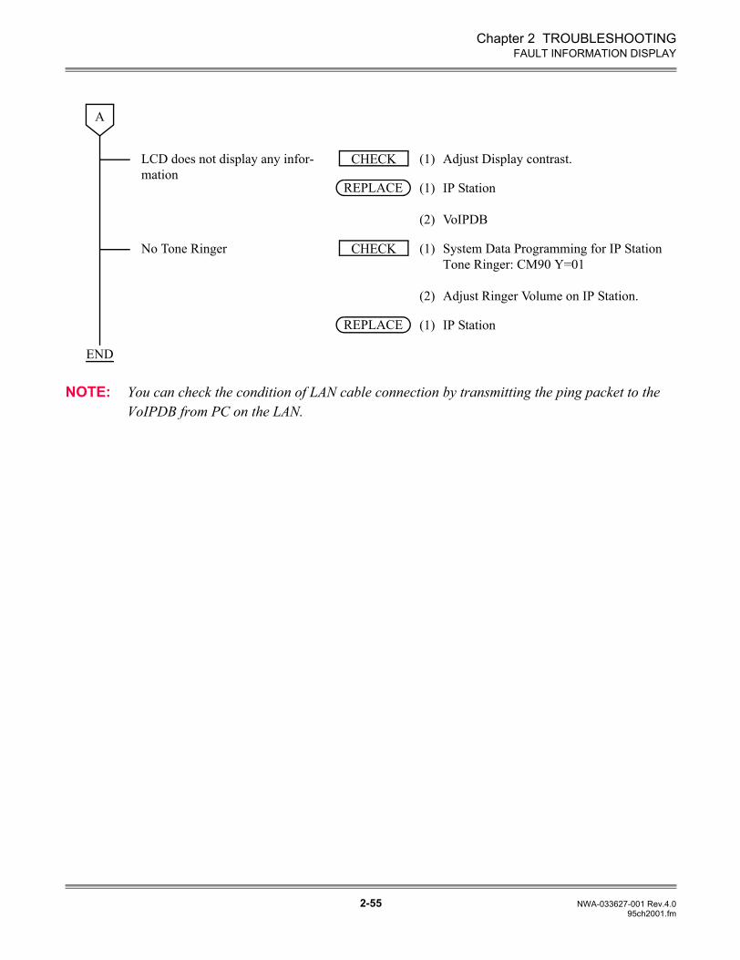
Chapter 2 TROUBLESHOOTING
2-55 NWA-033627-001 Rev.4.095ch2001.fm
FAULT INFORMATION DISPLAY
NOTE: You can check the condition of LAN cable connection by transmitting the ping packet to the VoIPDB from PC on the LAN.
LCD does not display any infor-mation
(1) Adjust Display contrast.
(1)
(2)
IP Station
VoIPDB
No Tone Ringer (1)
(2)
System Data Programming for IP Station Tone Ringer: CM90 Y=01
Adjust Ringer Volume on IP Station.
(1) IP Station
A
CHECK
REPLACE
CHECK
REPLACE
END
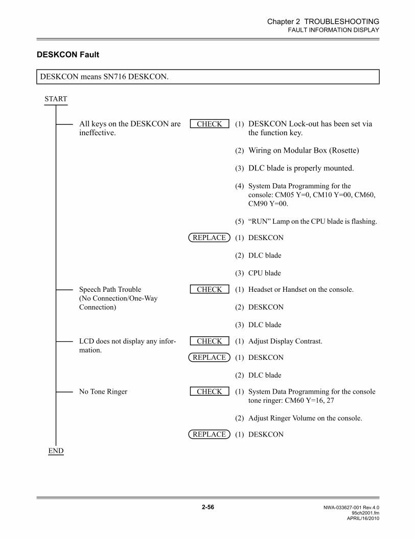
Chapter 2 TROUBLESHOOTING
2-56 NWA-033627-001 Rev.4.095ch2001.fm
FAULT INFORMATION DISPLAY
DESKCON Fault
DESKCON means SN716 DESKCON.
All keys on the DESKCON are ineffective.
(1)
(2)
(3)
(4)
(5)
DESKCON Lock-out has been set via the function key.
Wiring on Modular Box (Rosette)
DLC blade is properly mounted.
System Data Programming for the console: CM05 Y=0, CM10 Y=00, CM60, CM90 Y=00.
“RUN” Lamp on the CPU blade is flashing.
(1)
(2)
(3)
DESKCON
DLC blade
CPU blade
Speech Path Trouble (No Connection/One-Way Connection)
(1)
(2)
(3)
Headset or Handset on the console.
DESKCON
DLC blade
LCD does not display any infor-mation.
(1) Adjust Display Contrast.
(1)
(2)
DESKCON
DLC blade
No Tone Ringer (1)
(2)
System Data Programming for the console tone ringer: CM60 Y=16, 27
Adjust Ringer Volume on the console.
(1) DESKCON
START
CHECK
REPLACE
CHECK
CHECK
REPLACE
CHECK
REPLACE
END
APRIL/16/2010
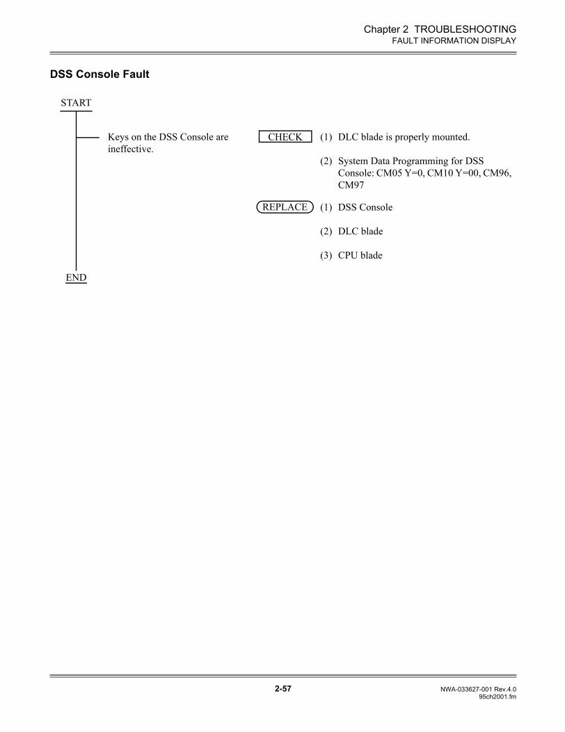
Chapter 2 TROUBLESHOOTING
2-57 NWA-033627-001 Rev.4.095ch2001.fm
FAULT INFORMATION DISPLAY
DSS Console Fault
Keys on the DSS Console are ineffective.
(1)
(2)
DLC blade is properly mounted.
System Data Programming for DSS Console: CM05 Y=0, CM10 Y=00, CM96, CM97
(1)
(2)
(3)
DSS Console
DLC blade
CPU blade
START
CHECK
REPLACE
END

2-58 NWA-033627-001 Rev.4.095ch2001.fm
THIS PAGE LEFT BLANK INTENTIONALLY.
NOVEMBER/21/2008


![NWA-033623-001 Issue 3 - TeleComcepts Command... · NWA-033623-001 ISSUE 3.0. ... [CMAA] DTI/BRT/PRT/CCT FUNCTIONS ... Dterm Dterm70 (Elite) Dterm75 (Series E) Dterm85 (Series i)](https://static.fdocuments.us/doc/165x107/5ad3738f7f8b9abd6c8df605/nwa-033623-001-issue-3-commandnwa-033623-001-issue-30-cmaa-dtibrtprtcct.jpg)