NUREG-1432 Vol. 1, Rev. 2 Standard Technical Specifications … · 2012-11-18 · Engineering...
189
NUREG-1432 Vol. 1, Rev. 2 Standard Technical Specifications Combustion Engineering Plants Specifications U.S. Nuclear Regulatory Commission Office of Nuclear Reactor Regulation Washington, DC 20555-0001
Transcript of NUREG-1432 Vol. 1, Rev. 2 Standard Technical Specifications … · 2012-11-18 · Engineering...

NUREG-1432 Vol. 1, Rev. 2
Standard Technical Specifications Combustion Engineering Plants
Specifications
U.S. Nuclear Regulatory Commission Office of Nuclear Reactor Regulation Washington, DC 20555-0001

NUREG-1432 Vol. 1, Rev. 2
Standard Technical Specifications Combustion Engineering Plants
Specifications
Manuscript Completed: April 2001 Date Published: June 2001
Division of Regulatory Improvement Programs Office of Nuclear Reactor Regulation U.S. Nuclear Regulatory Commission Washington, DC 20555-0001

"AVAIlABILITY OF REFERENCE MATERIALS IN NRC PUBLICATIONS
NRC Reference Material
As of November 1999, you may electronically access NUREG-series publications and other NRC records at NRC's Public Electronic Reading Room at www.nrc.gov/N RC/ADAMSfindex. html. Publicly released records include, to name a few, NU REG-series publications; Federal Register notices; applicant, licensee, and vendor documents and correspondence; NRC correspondence and internal memoranda; bulletins and information notices; inspection and investigative reports; licensee event reports; and Commission papers and their attachments.
NRC publications in the NUREG series, NRC regulations, and Title 10, Energy, in the Code of Federal Regulations may also be purchased from one of these two sources. 1. The Superintendent of Documents
U.S. Government Printing Office Mail Stop SSOP Washington, DC 20402-0001 Internet: bookstore.gpo.gov Telephone: 202-512-1800 Fax: 202-512-2250
2. The National Technical Information Service Springfield, VA 22161-0002 www.ntis.gov 1-800-553-6847 or, locally, 703-605-6000
A single copy of each NRC draft report for comment is available free, to the extent of supply, upon written request as follows: Address: Office of the Chief Information Officer,
Reproduction and Distribution Services Section
U.S. Nuclear Regulatory Commission Washington, DC 20555-0001
E-mail: DISTRIBUTION @nrc.gov Facsimile: 301-415-2289
Some publications in the NUREG series that are posted at NRC's Web site address www.nrc.gov/NRC/NUREGS/indexnum.html are updated periodically and may differ from the last printed version. Although references to material found on a Web site bear the date the material was accessed, the material available on the date cited may subsequently be removed from the site.
-rNon-NRC Reference Material
Documents available from public and special technical libraries include all open literature items, such as books, journal articles, and transactions, Federal Register notices, Federal and State legislation, and congressional reports. Such documents as theses, dissertations, foreign reports and translations, and non-NRC conference proceedings may be purchased from their sponsoring organization.
Copies of industry codes and standards used in a substantive manner in the NRC regulatory process are maintained at
The NRC Technical Library Two White Flint North 11545 Rockville Pike Rockville, MD 20852-2738
These standards are available in the library for reference use by the public. Codes and standards are usually copyrighted and may be purchased from the originating organization or, if they are American National Standards, from
American National Standards Institute 11 West 4 2 nd Street New York, NY 10036-8002 www.ansi.org 212-642-4900
J.
Legally binding regulatory requirements are stated only in laws; NRC regulations; licenses, including technical specifications; or orders, not in NUREG-series publications. The views expressed in contractor-prepared publications in this series are not necessarily those of the NRC.
The NUREG series comprises (1) technical and administrative reports and books prepared by the staff (NUREG-XXXX) or agency contractors (NUREG/CR-XXXX), (2) proceedings of conferences (NUREG/CP-XXXX), (3) reports resulting from international agreements (NUREG/IA-XXXX), (4) brochures (NUREG/BR-XXXX), and (5) compilations of legal decisions and orders of the Commission and Atomic and Safety Licensing Boards and of Directors' decisions under Section 2.206 of NRC's regulations (NUREG-0750).
PREFACE
This NUREG contains the improved Standard Technical Specifications (STS) for Combustion Engineering plants. Revision 2 incorporates the cumulative changes to Revision 1, which was published in April 1995. The changes reflected in Revision 2 resulted from the experience gained from license amendment applications to convert to these improved STS or to adopt partial improvements to existing technical specifications. This publication is the result of extensive public technical meetings and discussions among the Nuclear Regulatory Commission (NRC) staff and various nuclear power plant licensees, Nuclear Steam Supply System (NSSS) Owners Groups, and the Nuclear Energy Institute (NEI). The improved STS were developed based on the criteria in the Final Commission Policy Statement on Technical Specifications Improvements for Nuclear Power Reactors, dated July 22, 1993 (58 FR 39132), which was subsequently codified by changes to Section 36 of Part 50 of Title 10 of the Code of Federal Regulations (10 CFR 50.36) (60 FR 36953). Licensees are encouraged to upgrade their technical specifications consistent with those criteria and conforming, to the practical extent, to Revision 2 to the improved STS. The Commission continues to place the highest priority on requests for complete conversions to the improved STS. Licensees adopting portions of the improved STS to existing technical specifications should adopt all related requirements, as applicable, to achieve a high degree of standardization and consistency.
The Table of Contents is now a Table of Contents / Revision Summary where the revision number and date are listed for each specification and bases, in lieu of traditional page numbers. Each limiting condition for operation (LCO) starts with page 1, with a specification, e.g., "2.0" or bases "B 2.0" number prefix. Subsequent approved revisions to sections will be noted in the table of contents, as well as on each affected page, using a decimal number to indicate the number of revisions to that section, along with the date, e.g., (Rev 2.3, 04/01/01) indicates the third approved change and date since Revision 2.0 was published. Additionally, the final page of each LCO section will be a historical listing of the changes affecting that section. This publication will be maintained in electronic format. Subsequent revisions will not be printed in hard copy. Users may access the subsequent revisions to the STS in the PDF format at (http://www.nrc.gov/NRR/sts/sts.htm). This Web site will be updated as needed and the contents may differ from the last printed version. Users may print or download copies from the NRC Web site.
PAPERWORK REDUCTION ACT STATEMENT
The information collections contained in this NUREG are covered by the requirements of 10 CFR Parts 20 and 50, which were approved by the Office of Management and Budget, approval numbers 3150-0014 and 0011.
PUBLIC PROTECTION NOTIFICATION
If a means used to impose an information collection does not display a currently valid OMB control number, the NRC may not conduct or sponsor, and a person is not required to respond to, the information collection.
Rev. 2, 04/30/01CEOG STS iii

1.0 USE AND APPLICATION 1.1 Definitions ................................................ 2 04/30/01 1.2 Logical Connectors ......................................... 2 04/30/01 1.3 Completion Times .......................................... 2 04/30/01 1.4 Frequency ................................................ 2 04/30/01
2.0 SAFETY LIMITS (Analog) ....................................... 2 04/30/01 2.1 SLs 2.2 SL Violations
2.0 SAFETY LIMITS (Digital) ........................................ 2 04/30/01 2.1 SLs 2.2 SL Violations
3.0 LIMITING CONDITION FOR OPERATION APPLICABILITY ............. 2 04/30/01 3.0 SURVEILLANCE REQUIREMENT APPLICABILITY ................... 2 04/30/01
3.1 REACTIVITY CONTROL SYSTEMS 3.1.1 SHUTDOWN MARGIN (Analog) ........................... 2 04/30/01 3.1.2 Reactivity Balance (Analog) .............................. 2 04/30/01 3.1.3 Moderator Temperature Coefficient (Analog) ................... 2 04/30/01 3.1.4 Control Element Assembly Alignment (Analog) ................. 2 04/30/01 3.1.5 Shutdown Control Element Assembly Insertion Limits (Analog) ..... 2 04/30/01 3.1.6 Regulating Control Element Assembly Insertion Limits (Analog) .... 2 04/30/01 3.1.7 Special Test Exceptions - SHUTDOWN MARGIN (Analog) ........ 2 04/30/01 3.1.8 Special Test Exceptions - MODES 1 and 2 (Analog) ............. 2 04/30/01
3.1.1 SHUTDOWN MARGIN (Digital) ............................. 2 04/30/01 3.1.2 Reactivity Balance (Digital) ................................. 2 04/30/01 3.1.3 Moderator Temperature Coefficient (Digital) ................... 2 04/30/01 3.1.4 Control Element Assembly Alignment (Digital) .................. 2 04/30/01 3.1.5 Shutdown Control Element Assembly Insertion Limits (Digital) ..... 2 04/30/01 3.1.6 Regulating Control Element Assembly Insertion Limits (Digital) ..... 2 04/30/01 3.1.7 Part Length Control Element Assembly Insertion Limits (Digital) .... 2 04/30/01 3.1.8 Special Test Exceptions - SHUTDOWN MARGIN (Digital) ........ 2 04/30/01 3.1.9 Special Test Exceptions - MODES 1 and 2 (Digital) .............. 2 04/30/01
3.2 POWER DISTRIBUTION LIMITS 3.2.1 Linear Heat Rate (LHR) (Analog) ............................ 2 04/30/01 3.2.2 Total Planar Radial Peaking Factor (FT) (Analog) ............... 2 04/30/01 3.2.3 Total Integrated Radial Peaking Factor (Fr) (Analog) ............. 2 04/30/01 3.2.4 AZIMUTHAL POWER TILT (Tq) (Analog) ..................... 2 04/30/01 3.2.5 AXIAL SHAPE INDEX (ASI) (Analog) ........................ 2 04/30/01
3.2.1 Linear Heat Rate (LHR) (Digital) ............................ 2 04/30/01 3.2.2 Planar Radial Peaking Factors (Fxy) (Digital) ................... 2 04/30/01 3.2.3 AZIMUTHAL POWER TILT (Tq) (Digital) ...................... 2 04/30/01
CEOG STS v Rev. 2, 04/30/01
TABLE OF CONTENTS / REVISION SUMMARY Revision - Date

TABLE OF CONTENTS / REVISION SUMMARY
3.2 POWER DISTRIBUTION LIMITS (continued)
3.2.4 Departure From Nucleate Boiling Ratio (DNBR) (Digital) ......... 2 04/30/01 3.2.5 AXIAL SHAPE INDEX (ASI) (Digital) ......................... 2 04/30/01
INSTRUMENTATION Reactor Protective System Instrumentation - Operating (Analog) ... 2 Reactor Protective System Instrumentation - Shutdown (Analog) ... 2 Reactor Protective System Logic and Trip Initiation (Analog) ....... 2 Engineered Safety Features Actuation System Instrumentation
(Analog) ......................................... . . 2 Engineered Safety Features Actuation System Logic and Manual
Trip (Analog) ........................................ 2 Diesel Generator (DG) - Loss of Voltage Start (LOVS) (Analog) .... 2 Containment Purge Isolation Signal (CPIS) (Analog) ............. 2 Control Room Isolation Signal (CRIS) (Analog) ................. 2 Chemical and Volume Control System (CVCS) Isolation Signal
(A nalog) ............................................ 2 Shield Building Filtration Actuation Signal (SBFAS) (Analog) ........ 2 Post Accident Monitoring (PAM) Instrumentation (Analog)...'....... 2 Remote Shutdown System (Analog) ......................... 2 [Logarithmic] Power Monitoring Channels (Analog) .............. 2
3.3 3.3.1 3.3.2 3.3.3 3.3.4
3.3.5
3.3.6 3.3.7 3.3.8 3.3.9
3.3.10 3.3.11 3.3.12 3.3.13
3.3.1 3.3.2 3.3.3 3.3.4 3.3.5
3.3.6
3.3.7 3.3.8 3.3.9 3.3.10 3.3.11 3.3.12 3.3.13
3.4 3.4.1
3.4.2 3.4.3 3.4.4 3.4.5 3.4.6 3.4.7
REACTOR COOLANT SYSTEM (RCS) RCS Pressure, Temperature, and Flow [Departure from Nucleate
Boiling (DNB3 ] Lim its ............................... RCS Minimum Temperature for Criticality .................. RCS Pressure and Temperature (P/T) Limits ................ RCS Loops - MODES 1 and 2 ........................... RCS Loops - MODE 3 ................................. RCS Loops - MODE 4 ................................. RCS Loops - MODE 5, Loops Filled .......................
2 2 2 2
04/30/01 04/30/01 04/30/01
04/30/01
04/30/01 04/30/01 04/30/01 04/30/01
04/30/01 04/30/01 04/30/01 04/30/01 04/30/01
04/30/01 04/30/01 04/30/01 04/30/01
2 04/30/01
2 04/30/01 2 04/30/01 2 04/30/01 2 04/30/01 2 04/30/01 2 04/30/01 2 04/30/01 2 04/30/01
.2
.2
.2
.2
.2
.2
.2
04/30/01 04/30/01 04/30/01 04/30/01 04/30/01 04/30/01 04/30/01
CEOG STS
Reactor Protective System Instrumentation - Operating (Digital) .... Reactor Protective System Instrumentation - Shutdown (Digital) .... Control Element Assembly Calculators (CEACs) (Digital) ......... Reactor Protective System Logic and Trip Initiation (Digital) ....... Engineered Safety Features Actuation System Instrumentation
(D ig ital) ............................................ Engineered Safety Features Actuation System Logic and Manual
T rip (D igital) ......................................... Diesel Generator (DG) - Loss of Voltage Start (LOVS) (Digital) ..... Containment Purge Isolation Signal (CPIS) (Digital) ............. Control Room Isolation Signal (CRIS) (Digital) .................. Fuel Handling Isolation Signal (FHIS) (Digital) .................. Post Accident Monitoring (PAM) Instrumentation (Digital) ......... Remote Shutdown System (Digital) .......................... [Logarithmic] Power Monitoring Channels (Digital) ...............
Revision - Date
vi Rev. 2, 04/30/01

TABLE OF CONTENTS / REVISION SUMMARY
3.4 REACTOR COOLANT SYSTEM (RCS) (continued)
3.4.8 RCS Loops - MODE 5, Loops Not Filled ...................... 2 04/30/01 3.4.9 Pressurizer ............................................. 2 04/30/01 3.4.10 Pressurizer Safety Valves ................................. 2 04/30/01 3.4.11 Pressurizer Power Operated Relief Valves (PORVs) ............. 2 04/30/01 3.4.12 Low Temperature Overpressure Protection (LTOP) System ....... 2 04/30/01 3.4.13 RCS Operational LEAKAGE ............................... 2 04/30/01 3.4.14 RCS Pressure Isolation Valve (PIV) Leakage .................. 2 04/30/01 3.4.15 RCS Leakage Detection Instrumentation ...................... 2 04/30/01 3.4.16 RCS Specific Activity ..................................... 2 04/30/01 3.4.17 Special Test Exceptions (STE) RCS Loops .................... 2 04/30/01
3.5 EMERGENCY CORE COOLING SYSTEMS (ECCS) 3.5.1 Safety Injection Tanks (SITs) ............................... 2 04/30/01 3.5.2 ECCS - Operating ....................................... 2 04/30/01 3.5.3 ECCS - Shutdown ..................................... 2 04/30/01 3.5.4 Refueling Water Tank (RWT) .............................. 2 04/30/01 3.5.5 Trisodium Phosphate (TSP) .................................. 2 04/30/01
3.6 CONTAINMENT SYSTEMS 3.6.1 Containment (Atmospheric and Dual) ........................ 2 04/30/01 3.6.2 Containment Air Locks (Atmospheric and Dual) ................. 2 04/30/01 3.6.3 Containment Isolation Valves (Atmospheric and Dual) ............ 2 04/30/01 3.6.4 Containment Pressure (Atmospheric and Dual) ................. 2 04/30/01 3.6.5 Containment Air Temperature (Atmospheric and Dual) ........... 2 04/30/01 3.6.6A Containment Spray and Cooling System (Atmospheric and Dual)
(Credit taken for iodine removal by the Containment Spray System ) ............................................ 2 04/30/01
3.6.6B Containment Spray and Cooling Systems (Atmospheric and Dual) (Credit not taken for iodine removal by the Containment Spray System ) ............................................ 2 04/30/01
3.6.7 Spray Additive System (Atmospheric and Dual) ................. 2 04/30/01 3.6.8 Hydrogen Recombiners (Atmospheric and Dual) (if permanently
installed) ............................................ 2 04/30/01 3.6.9 Hydrogen Mixing System (HMS) (Atmospheric and Dual) ......... 2 04/30/01 3.6.10 Iodine Cleanup System (ICS) (Atmospheric and Dual) ............ 2 04/30/01 3.6.11 Shield Building (Dual) ..................................... 2 04/30/01 3.6.12 Vacuum Relief Valves (Dual) ............................... 2 04/30/01 3.6.13 Shield Building Exhaust Air Cleanup System (SBEACS) (Dual) ..... 2 04/30/01
3.7 PLANT SYSTEMS 3.7.1 Main Steam Safety Valves (MSSVs) ......................... 2 04/30/01 3.7.2 Main Steam Isolation Valves (MSIVs) ........................ 2 04/30/01 3.7.3 Main Feedwater Isolation Valves (MFIVs) [and [MFIV] Bypass
Valves ............................................. 2 04/30/01 3.7.4 Atmospheric Dump Valves (ADVs) .......................... 2 04/30/01 3.7.5 Auxiliary Feedwater (AFW) System .......................... 2 04/30/01
Rev. 2, 04/30/01
Revision - Date
CEOG STS vii

TABLE OF CONTENTS / REVISION SUMMARY
3.7 PLANT SYSTEMS (continued)
3.7.6 Condensate Storage Tank (CST) ............................ 2 04/30/01 3.7.7 Component Cooling Water (CCW) System .................... 2 04/30/01 3.7.8 Service Water System (SWS) .............................. 2 04/30/01 3.7.9 Ultimate Heat S3ink (UHS) ................................. 2 04/30/01 3.7.10 Essential Chilled Water (ECW) ............................. 2 04/30/01 3.7.11 Control Room Emergency Air Cleanup System (CREACS) ........ 2 04/30/01 3.7.12 Control Room Emergency Air Temperature Control System
(CREATCS) ........................................ 2 04/30/01 3.7.13 Emergency Core Cooling System (ECCS) Pump Room Exhaust
Air Cleanup System (PREACS) .......................... 2 04/30/01 3.7.14 Fuel Building Air Cleanup System (FBACS) .................... 2 04/30/01 3.7.15 Penetration Room Exhaust Air Cleanup System (PREACS) ....... 2 04/30/01
3.7.16 Fuel Storage Pool Water Level ............................. 2 04/30/01 [3.7.17 Fuel Storage Pool Boron Concentration ....................... 2 04/30/01 ] 3.7.18 Spent Fuel Assembly Storage .............................. 2 04/30/01] 3.7.19 Secondary Specific Activity ................................ 2 04/30/01
3.8 ELECTRICAL POWER SYSTEMS 3.8.1 AC Sources - Operating .......... ......................... 2 04/30/01 3.8.2 AC Sources - Shutdown ................................... 2 04/30/01 3.8.3 Diesel Fuel Oil, lube Oil, and Starting Air ..................... 2 04/30/01 3.8.4 DC Sources - L Operating ................................... 2 04/30/01 3.8.5 DC Sources - Shutdown ................................... 2 04/30/01 3.8.6 Battery Parameters ...................................... 2 04/30/01 3.8.7 Inverters - Operating ..................................... 2 04/30/01 3.8.8 Inverters - Shutdown ..................................... 2 04/30/01 3.8.9 Distribution Systems - Operating ............................ 2 04/30/01 3.8.10 Distribution Systems - Shutdown ............................ 2 04/30/01
3.9 REFUELING OPERATIONS 3.9.1 Boron Concentration ..................................... 2 04/30/01 3.9.2 Nuclear Instrumentation ................................... 2 04/30/01 3.9.3 Containment Penetrations .................... ' *............. ' 2 04/30/01 3.9.4 Shutdown Cooling (SDC) and Coolant Circulation - High Water
Level .............................................. 2 04/30/01 3.9.5 Shutdown Cooling (SDC) and Coolant Circulation - Low Water
Level .............................................. 2 04/30/01 3.9.6 Refueling W ater Level .................................... 2 04/30/01
4.0 DESIGN FEATURES ........................................... 2 04/30/01 4.1 Site Location 4.2 Reactor Core 4.3 Fuel Storage
CEOG STS viii Rev. 2, 04/30/01
Revision - Date

5.0 ADMINISTRATIVE CONTROLS 5.1 Responsibility .............................................. 2 04/30/01 5.2 Organization .............................................. 2 04/30/01 5.3 Unit Staff Qualifications ...................................... 2 04/30/01 5.4 Procedures ............................................. 2 04/30/01 5.5 Programs and Manuals ...................................... 2 04/30/01 5.6 Reporting Requirements ..................................... 2 04/30/01
[5.7 High Radiation Area ......................................... 2 04/30/01]
Rev. 2, 04/30/01
TABLE OF CONTENTS / REVISION SUMMARY Revision - Date
CEOG STS ix

Definitions 1.1
1.0 USE AND APPLICATION
1.1 Definitions
- NOTE The defined terms of this section appear in capitalized type and are applicable throughout these Technical Specifications and Bases.
Term Definition
ACTIONS
AXIAL SHAPE INDEX (ASI)
ACTIONS shall be that part of a Specification that prescribes Required Actions to be taken under designated Conditions within specified Completion Times.
ASI shall be the power generated in the lower half of the core less the power generated in the upper half of the core, divided by the sum of the power generated in the lower and upper halves of the core.
ASI = (LOWER - UPPER) / (LOWER + UPPER)
AZIMUTHAL POWER TILT (Tq) - Digital
AZIMUTHAL POWER TILT (Tq) - Analog
CHANNEL CALIBRATION
AZIMUTHAL POWER TILT shall be the power asymmetry between azimuthally symmetric fuel assemblies.
AZIMUTHAL POWER TILT shall be the maximum of the difference between the power generated in any core quadrant (upper or lower) (Pquad) and the average power of all quadrants (Payg) in that half (upper or lower) of the core, divided by the average power of all quadrants in that half (upper or lower) of the core.
Tq = Max I (Pquad - Pavg) / Pavg I
A CHANNEL CALIBRATION shall be the adjustment, as necessary, of the channel output such that it responds within the necessary range and accuracy to known values of the parameter that the channel monitors. The CHANNEL CALIBRATION shall encompass all devices in the channel required for channel OPERABILITY and the CHANNEL FUNCTIONAL TEST. Calibration of instrument channels with resistance temperature detector (RTD) or thermocouple sensors may consist of an inplace qualitative assessment of sensor behavior and normal calibration of the remaining adjustable devices in the channel. The CHANNEL
Rev. 2, 04/30/01CEOG STS 1.1 -1

Definitions 1.1
1.1 Definitions
CHANNEL CALIBRATION (continued)
CALIBRATION may be performed by means of any series of sequential, overlapping, or total channel steps.
CHANNELCHECK A CHANNEL CHECK shall be the qualitative assessment, by observation, of channel behavior during operation. This determination shall include, where possible, comparison of the channel indication and status to other indications or status derived from independent instrument channels measuring the same parameter.
CHANNEL FUNCTIONAL TEST A CHANNEL FUNCTIONAL TEST shall be:
a. Analog and bistable channels - the injection of a simulated or actual signal into the channel as close to the sensor as practicable to verify OPERABILITY of all devices in the channel required for channel OPERABILITY, and
b. Digital computer channels - the use of diagnostic programs to test digital computer hardware and the injection of simulated process data into the channel to verify OPERABILITY of all devices in the channel required for channel OPERABILITY.
The CHANNEL FUNCTIONAL TEST may be performed by means of any series of sequential, overlapping, or total channel steps so that the entire channel is tested.
CORE ALTERATION
CORE OPERATING LIMITS REPORT (COLR)
CORE ALTERATION shall be the movement of any fuel, sources, or reactivity control components [excluding control element assemblies (CEAs) withdrawn into the upper guide structure], within the reactor vessel with the vessel head removed and fuel in the vessel. Suspension of CORE ALTERATIONS shall not preclude completion of movement of a component to a safe position.
The COLR is the unit specific document that provides cycle specific parameter limits for the current reload cycle. These cycle specific parameter limits shall be determined for each reload cycle in accordance with Specification 5.6.5. Plant operation within these limits is addressed in individual Specifications.
CEOG STS Rev. 2, 04/30/011.1-2

Definitions 1.1
1.1 Definitions
DOSE EQUIVALENT 1-131
E - AVERAGE DISINTEGRATION ENERGY
ENGINEERED SAFETY FEATURE (ESF) RESPONSE TIME
LEAKAGE
DOSE EQUIVALENT 1-131 shall be that concentration of 1-131 (microcuries/gram) that alone would produce the same thyroid dose as the quantity and isotopic mixture of 1-131, 1-132, 1-133, 1-134, and 1-135 actually present. The thyroid dose conversion factors used for this calculation shall be those listed in [Table IIl of TID-14844, AEC, 1962, "Calculation of Distance Factors for Power and Test Reactor Sites," or those listed in Table E-7 of Regulatory Guide 1.109, Rev. 1, NRC, 1977, or ICRP 30, Supplement to Part 1, page 192-212, Table titled, "Committed Dose Equivalent in Target Organs or Tissues per Intake of Unit Activity"].
E shall be the average (weighted in proportion to the concentration of each radionuclide in the reactor coolant at the time of sampling) of the sum of the average beta and gamma energies per disintegration (in MeV) for isotopes, other than iodines, with half lives > [15] minutes, making up at least 95% of the total noniodine activity in the coolant.
The ESF RESPONSE TIME shall be that time interval from when the monitored parameter exceeds its ESF actuation setpoint at the channel sensor until the ESF equipment is capable of performing its safety function (i.e., the valves travel to their required positions, pump discharge pressures reach their required values, etc.). Times shall include diesel generator starting and sequence loading delays, where applicable. The response time may be measured by means of any series of sequential, overlapping, or total steps so that the entire response time is measured. In lieu of measurement, response time may be verified for selected components provided that the components and methodology for verification have been previously reviewed and approved by the NRC.
LEAKAGE shall be:
a. Identified LEAKAGE
1. LEAKAGE, such as that from pump seals or valve packing (except reactor coolant pump (RCP) seal water injection or leakoff), that is captured and conducted to collection systems or a sump or collecting tank,
Rev. 2, 04/30/01CEOG STS 1.1 -3

Definitions 1.1
1.1 Definitions
LEAKAGE (continued)
MODE
OPERABLE - OPERABILITY
PHYSICS TESTS
2. LEAKAGE into the containment atmosphere from sources that are both specifically located and known either not to interfere with the operation of leakage detection systems or not to be pressure boundary LEAKAGE, or
3. Reactor Coolant System (RCS) LEAKAGE through a steam generator (SG) to the Secondary System,
b. Unidentified LEAKAGE
All LEAKAGE (except RCP seal water injection or leakoff) that is not identified LEAKAGE, and
c. Pressure Boundary LEAKAGE
LEAKAGE (except SG LEAKAGE) through a nonisolable fault in an RCS component body, pipe wall, or vessel wall.
A MODE shall correspond to any one inclusive combination of core reactivity condition, power level, average reactor coolant temperature, and reactor vessel head closure bolt tensioning specified in Table 1.1-1 with fuel in the reactor vessel.
A system, subsystem, train, component, or device shall be OPERABLE or have OPERABILITY when it is capable of performing its specified safety function(s) and when all necessary attendant instrumentation, controls, normal or emergency electrical power, cooling and seal water, lubrication, and other auxiliary equipment that are required for the system, subsystem, train, component, or device to perform its specified safety function(s) are also capable of performing their related support function(s).
PHYSICS TESTS shall be those tests performed to measure the fundamental nuclear characteristics of the reactor core and related instrumentation.
These tests are:
CEOG STS Rev. 2, 04/30/011.1 -4

Definitions 1.1
1.1 Definitions
PHYSICS TESTS (continued)
PRESSURE AND TEMPERATURE LIMITS REPORT (PTLR)
RATED THERMAL POWER (RTP)
REACTOR PROTECTION SYSTEM (RPS) RESPONSE TIME
SHUTDOWN MARGIN (SDM)
a. Described in Chapter [14, Initial Test Program] of the FSAR,
b. Authorized under the provisions of 10 CFR 50.59, or
c. Otherwise approved by the Nuclear Regulatory Commission.
The PTLR is the unit specific document that provides the reactor vessel pressure and temperature limits, including heatup and cooldown rates, for the current reactor vessel fluence period. These pressure and temperature limits shall be determined for each fluence period in accordance with Specification 5.6.6. Plant operation within these operating limits is addressed in LCO 3.4.3, "RCS Pressure and Temperature (PIT) Limits," and LCO 3.4.12, "Low Temperature Overpressure Protection (LTOP) System."
RTP shall be a total reactor core heat transfer rate to the reactor coolant of [3410] MWt.
The RPS RESPONSE TIME shall be that time interval from when the monitored parameter exceeds its RPS trip setpoint at the channel sensor until electrical power to the CEAs drive mechanism is interrupted. The response time may be measured by means of any series of sequential, overlapping, or total steps so that the entire response time is measured. In lieu of measurement, response time may be verified for selected components provided that the components and methodology for verification have been previously reviewed and approved by the NRC.
SDM shall be the instantaneous amount of reactivity by which the reactor is subcritical or would be subcritical from its present condition assuming:
a. All full length CEAs (shutdown and regulating) are fully inserted except for the single CEA of highest reactivity worth, which is assumed to be fully withdrawn. However, with all CEAs verified fully inserted by two independent means, it is not necessary to account for a stuck CEA in the SDM calculation. With any CEAs not capable of being fully inserted, the reactivity worth of
Rev. 2, 04/30/01CEOG STS 1.1 -5

Definitions 1.1
1.1 Definitions
SDM (continued)
STAGGERED TEST BASIS
THERMAL POWER
these CEAs must be accounted for in the determination of SDM, and
[b. There is no change in part length CEA position.]
A STAGGERED TEST BASIS shall consist of the testing of one of the systems, subsystems, channels, or other designated components during the interval specified by the Surveillance Frequency, so that all systems, subsystems, channels, or other designated components are tested during n Surveillance Frequency intervals, where n is the total number of systems, subsystems, channels, or other designated components in the associated function.
THERMAL POWER shall be the total reactor core heat transfer rate to the reactor coolant.
CEOG STS Rev. 2, 04/30/01
-1
1.1-6

Definitions 1.1
Table 1.1-1 (page 1 of 1) MODES
REACTIVITY % RATED AVERAGE
MODE TITLE CONDITION THERMAL REACTOR COOLANT
(kenf) POWER(a) TEMPERATURE (OF)
1 Power Operation > 0.99 > 5 NA
2 Startup >0.99 •_ 5 NA
3 Hot Standby < 0.99 NA _ [350]
4 Hot Shutdown(b) < 0.99 NA [350] > Tavg > [200]
5 Cold Shutdown(b) < 0.99 NA _ [200]
6 Refueling(c) NA NA NA
Excluding decay heat.
All reactor vessel head closure bolts fully tensioned.
One or more reactor vessel head closure bolts less than fully tensioned.
Rev. 2, 04/30/01
(a)
(b)
(c)
CEOG STS 1.1 -7

Logical Connectors 1.2
1.0 USE AND APPLICATION
1.2 Logical Connectors
PURPOSE The purpose of this section is to explain the meaning of logical connectors.
Logical connectors are used in Technical Specifications (TS) to discriminate between, and yet connect, discrete Conditions, Required Actions, Completion Times, Surveillances, and Frequencies. The only logical connectors that appear in TS are AND and OR. The physical arrangement of these connectors constitutes logical conventions with specific meanings.
BACKGROUND Several levels of logic may be used to state Required Actions. These levels are identified by the placement (or nesting) of the logical connectors and by the number assigned to each Required Action. The first level of logic is identified by the first digit of the number assigned to a Required Action and the placement of the logical connector in the first level of nesting (i.e., left justified with the number of the Required Action). The successive levels of logic are identified by additional digits of the Required Action number and by successive indentions of the logical connectors.
When logical connectors are used to state a Condition, Completion Time, Surveillance, or Frequency, only the first level of logic is used, and the logical connector is left justified with the statement of the Condition, Completion Time, Surveillance, or Frequency.
EXAMPLES The following examples illustrate the use of logical connectors.
Rev. 2, 04/30/01CEOG STS 1.2- 1

Logical Connectors 1.2
1.2 Logical Connectors
EXAMPLES (continued)
EXAMPLE 1.2-1
ACTIONS
CONDITION REQUIRED ACTION COMPLETION TIME
A. ICO not met. A.1 Verify...
AND
A.2 Restore...
In this example the logical connector AND is used to indicate that when in Condil:ion A, both Required Actions A.1 and A.2 must be completed.
CEOG STS 1.2-2
Rev. 2, 04/30/01CEOG STS 1.2- 2

Logical Connectors 1.2
1.2 Logical Connectors
EXAMPLES (continued)
EXAMPLE 1.2-2
ACTIONS
CONDITION REQUIRED ACTION COMPLETION TIME
A. LCO not met. A.1 Trip...
OR
A.2.1 Verify...
AND
A.2.2.1 Reduce...
OR
A.2.2.2 Perform...
OR
A.3 Align...
This example represents a more complicated use of logical connectors. Required Actions A.1, A.2, and A.3 are alternative choices, only one of which must be performed as indicated by the use of the logical connector OR and the left justified placement. Any one of these three Actions may be chosen. If A.2 is chosen, then both A.2.1 and A.2.2 must be performed as indicated by the logical connector AND. Required Action A.2.2 is met by performing A.2.2.1 or A.2.2.2. The indented position of the logical connector OR indicates that A.2.2.1 and A.2.2.2 are alternative choices, only one of which must be performed.
Rev. 2, 04/30/01CEOG STS 1.2- 3

Completion Times 1.3
1.0 USE AND APPLICATION
1.3 Completion Times
PURPOSE The purpose of this section is to establish the Completion Time convention and to provide guidance for its use.
BACKGROUND Limiting Conditions for Operation (LCOs) specify minimum requirements for ensuring safe operation of the unit. The ACTIONS associated with an LCO state Conditions that typically describe the ways in which the requirements of the LCO can fail to be met. Specified with each stated Condition are Required Action(s) and Completion Time(s).
DESCRIPTION The Completion Time is the amount of time allowed for completing a Required Action. It is referenced to the time of discovery of a situation (e.g., inoperable equipment or variable not within limits) that requires entering an ACTIONS Condition unless otherwise specified, providing the unit is in a MODE or specified condition stated in the Applicability of the LCO. Required Actions must be completed prior to the expiration of the specified Completion Time. An ACTIONS Condition remains in effect and the Required Actions apply until the Condition no longer exists or the unit is not within the LCO Applicability.
If situations are discovered that require entry into more than one Condition at a time within a single LCO (multiple Conditions), the Required Actions for each Condition must be performed within the associated Completion Time. When in multiple Conditions, separate Completion Times are tracked for each Condition starting from the time of discovery of the situation that required entry into the Condition.
Once a Condition has been entered, subsequent trains, subsystems, components, or variables expressed in the Condition, discovered to be inoperable or not within limits, will not result in separate entry into the Condition, unless specifically stated. The Required Actions of the Condition continue to apply to each additional failure, with Completion Times based on initial entry into the Condition.
However, when a subsequent train, subsystem, component, or variable expressed in the Condition is discovered to be inoperable or not within limits, the Completion Time(s) may be extended. To apply this Completion Time extension, two criteria must first be met. The subsequent inoperability:
a. Must exist concurrent with the first inoperability and
Rev. 2, 04/30/01CEOG STS 1.3- 1

Completion Times 1.3
1.3 Completion Times
DESCRIPTION (continued)
b. Must remain inoperable or not within limits after the first inoperability is resolved.
The total Completion Time allowed for completing a Required Action to address the subsequent inoperability shall be limited to the more restrictive of either:
a. The stated Completion Time, as measured from the initial entry into the Condition, plus an additional 24 hours or
b. rhe stated Completion Time as measured from discovery of the subsequent inoperability.
The above Completion Time extensions do not apply to those Specifications that have exceptions that allow completely separate re-entry into the Condition (for each train, subsystem, component, or variable expressed in the Condition) and separate tracking of Completion Times based on this re-entry. These exceptions are stated in individual Specifications.
The above Completion Time extension does not apply to a Completion Time with a modified "time zero." This modified "time zero" may be expressed as a repetitive time (i.e., "once per 8 hours," where the Completion Time is referenced from a previous completion of the Required Action versus the time of Condition entry) or as a time modified by the phrase "from discovery..." Example 1.3-3 illustrates one use of this type of Completion Time. The 10 day Completion Time specified for Conditions A and B in Example 1.3-3 may not be extended.
EXAMPLES The following examples illustrate the use of Completion Times with different types of Conditions and changing Conditions.
Rev. 2, 04/30/01CEOG STS 1.3 -2

Completion Times 1.3
1.3 Completion Times
EXAMPLES (continued)
EXAMPLE 1.3-1
ACTIONS
CONDITION REQUIRED ACTION COMPLETION TIME
B. Required B.1 Be in MODE 3. 6 hours Action and associated AND Completion Time not met. B.2 Be in MODE 5. 36 hours
Condition B has two Required Actions. Each Required Action has its own separate Completion Time. Each Completion Time is referenced to the time that Condition B is entered.
The Required Actions of Condition B are to be in MODE 3 within 6 hours AND in MODE 5 within 36 hours. A total of 6 hours is allowed for reaching MODE 3 and a total of 36 hours (not 42 hours) is allowed for reaching MODE 5 from the time that Condition B was entered. If MODE 3 is reached within 3 hours, the time allowed for reaching MODE 5 is the next 33 hours because the total time allowed for reaching MODE 5 is 36 hours.
If Condition B is entered while in MODE 3, the time allowed for reaching MODE 5 is the next 36 hours.
Rev. 2, 04/30/01CEOG STS 1.3-3

Completion Times 1.3
1.3 Completion Times
EXAMPLES (continued)
EXAMPLE 1.3-2
ACTIONS
CONDITION REQUIRED ACTION COMPLETION TIME
A. One pump A.1 Restore pump to 7 days inoperable. OPERABLE
status.
B. Required B.1 Be in MODE 3. 6 hours Action and associated AND Completion Time not met. B.2 Be in MODE 5. 36 hours
When a pump is declared inoperable, Condition A is entered. If the pump is not restored to OPERABLE status within 7 days, Condition B is also entered and the Completion Time clocks for Required Actions B.1 and B.2 start. If the inoperable pump is restored to OPERABLE status after Condition B is entered, Condition A and B are exited, and therefore, the Required Actions of Condition B may be terminated.
When a second pump is declared inoperable while the first pump is still inoperable, Condition A is not re-entered for the second pump. LCO 3.0.3 is entered, since the ACTIONS do not include a Condition for more than one inoperable pump. The Completion Time clock for Condition A does not stop after LCO 3.0.3 is entered, but continues to be trackedc from the time Condition A was initially entered.
While in LCO 3.0.3, if one of the inoperable pumps is restored to OPERABLE status and the Completion Time for Condition A has not expired, LCO 3.0.3 may be exited and operation continued in accordance with Condition A.
While in LCO 3.0.3, if one of the inoperable pumps is restored to OPERABLE status and the Completion Time for Condition A has expired, LCO 3.0.3 may be exited and operation continued in accordance with Condition B. The Completion Time for Condition B is tracked from the time the Condition A Completion Time expired.
Rev. 2, 04/30/01CEOG STS 1.3- 4

Completion Times 1.3
1.3 Completion Times
EXAMPLES (continued)
On restoring one of the pumps to OPERABLE status, the Condition A Completion Time is not reset, but continues from the time the first pump was declared inoperable. This Completion Time may be extended if the pump restored to OPERABLE status was the first inoperable pump. A 24 hour extension to the stated 7 days is allowed, provided this does not result in the second pump being inoperable for > 7 days.
EXAMPLE 1.3-3
ACTIONS
CONDITION REQUIRED ACTION COMPLETION TIME
A. One A.1 Restore Function X 7 days Function X train to OPERABLE train status. AND inoperable.
10 days from discovery of failure to meet the LCO
B. One B.1 Restore Function Y 72 hours Function Y train to OPERABLE train status. AND inoperable.
10 days from discovery of failure to meet the LCO
C. One C.1 Restore Function X 72 hours Function X train to OPERABLE train status. inoperable.
OR AND
C.2 Restore Function Y 72 hours One train to OPERABLE Function Y status. train inoperable.
When one Function X train and one Function Y train are inoperable,
Rev. 2, 04/30/01CEOG STS 1.3- 5

Completion Times 1.3
1.3 Completion Times
EXAMPLES (continued)
Condition A and Condition B are concurrently applicable. The Completion Times for Condition A and Condition B are tracked separately for each train starting from the time each train was declared inoperable and the Condition was entered. A separate Completion Time is established for Condition C and tracked from the time the second train was declared inoperable (i.e., the time the situation described in Condition C was discovered).
If Required Action C.2 is completed within the specified Completion Time, Condil:ions B and C are exited. If the Completion Time for Required Action A.1 has not expired, operation may continue in accordance with Condilion A. The remaining Completion Time in Condition A is measured from the time the affected train was declared inoperable (i.e., initial entry into Condition A).
The Completion Times of Conditions A and B are modified by a logical connector, with a separate 10 day Completion Time measured from the time it was discovered the LCO was not met. In this example, without the separate Completion Time, it would be possible to alternate between Conditions A, B, and C in such a manner that operation could continue indefinitely without ever restoring systems to meet the LCO. The separate Completion Time modified by the phrase "from discovery of failure to meet the LCO" is designed to prevent indefinite continued operation while not meeting the LCO. This Completion Time allows for an exception to the normal "time zero" for beginning the Completion Time "clock." In this instance, the Completion Time "time zero" is specified as commencing at the time the LCO was initially not met, instead of at the time the associated Condition was entered.
CEOG STS Rev. 2, 04/30/011.3 -6

Completion Times 1.3
1.3 Completion Times
EXAMPLES (continued)
EXAMPLE 1.3-4
ACTIONS
CONDITION REQUIRED ACTION COMPLETION TIME
A. One or more A.1 Restore valve(s) to 4 hours valves OPERABLE status. inoperable.
B. Required B.1 Be in MODE 3. 6 hours Action and associated AND Completion Time not met. B.2 Be in MODE 4. 12 hours
A single Completion Time is used for any number of valves inoperable at the same time. The Completion Time associated with Condition A is based on the initial entry into Condition A and is not tracked on a per valve basis. Declaring subsequent valves inoperable, while Condition A is still in effect, does not trigger the tracking of separate Completion Times.
Once one of the valves has been restored to OPERABLE status, the Condition A Completion Time is not reset, but continues from the time the first valve was declared inoperable. The Completion Time may be extended if the valve restored to OPERABLE status was the first inoperable valve. The Condition A Completion Time may be extended for up to 4 hours provided this does not result in any subsequent valve being inoperable for > 4 hours.
If the Completion Time of 4 hours (including the extension) expires while one or more valves are still inoperable, Condition B is entered.
Rev. 2, 04/30/01CEOG STS 1.3- 7

Completion Times 1.3
1.3 Completion Times
EXAMPLES (continued)
EXAMPLE 1.3-5
ACTIONS
- NOTE Separate Condition entry is allowed for each inoperable valve.
CONDITION REQUIRED ACTION COMPLETION TIME
A. One or more A.1 Restore valve to 4 hours valves OPERABLE status. inoperable.
B. Required B.1 Be in MODE 3. 6 hours Action and associated AND Completion "Time not met. B.2 Be in MODE 4. 12 hours
The Note above the ACTIONS Table is a method of modifying how the Completion Time is tracked. If this method of modifying how the Completion Time is tracked was applicable only to a specific Condition, the Note would appear in that Condition rather than at the top of the ACTIONS Table.
The Note allows Condition A to be entered separately for each inoperable valve, and Completion Times tracked on a per valve basis. When a valve is declared inoperable, Condition A is entered and its Completion Time starts. If subsequent valves are declared inoperable, Condition A is entered for each valve and separate Completion Times start and are tracked for each valve.
If the Completion Time associated with a valve in Condition A expires, Condition B is entered for that valve. If the Completion Times associated with subsequent valves in Condition A expire, Condition B is entered separately for each valve and separate Completion Times start and are tracked for each valve. If a valve that caused entry into Condition B is restored to OPERABLE status, Condition B is exited for that valve.
Rev. 2, 04/30/01CEOG STS 1.3-8

Completion Times 1.3
1.3 Completion Times
EXAMPLES (continued)
Since the Note in this example allows multiple Condition entry and tracking of separate Completion Times, Completion Time extensions do not apply.
EXAMPLE 1.3-6
ACTIONS
CONDITION REQUIRED ACTION COMPLETION TIME
A. One channel A.1 Perform SR 3.x.x.x. Once per 8 hours inoperable.
OR
A.2 Reduce THERMAL 8 hours POWER to g 50% RTP.
B. Required B.1 Be in MODE 3. 6 hours Action and associated Completion Time not met.
Entry into Condition A offers a choice between Required Action A.1 orA.2. Required Action A.1 has a "once per" Completion Time, which qualifies for the 25% extension, per SR 3.0.2, to each performance after the initial performance. The initial 8 hour interval of Required Action A.1 begins when Condition A is entered and the initial performance of Required Action A.1 must be complete within the first 8 hour interval. If Required Action A.1 is followed and the Required Action is not met within the Completion Time (plus the extension allowed by SR 3.0.2), Condition B is entered. If Required Action A.2 is followed and the Completion Time of 8 hours is not met, Condition B is entered.
If after entry into Condition B, Required Action A.1 or A.2 is met, Condition B is exited and operation may then continue in Condition A.
Rev. 2, 04/30/01CEOG STS 1.3- 9

Completion Times 1.3
1.3 Completion Times
EXAMPLES (continued)
EXAMPLE 1.3-7
ACTIONS
CONDITION REQUIRED ACTION COMPLETION TIME
A. One A.1 Verify affected 1 hour subsystem subsystem isolated. inoperable. AND
Once per 8 hours thereafter
AND
A.2 Restore subsystem 72 hours to OPERABLE status.
B. Required B.1 Be in MODE 3. 6 hours Action and associated AND Completion Time not met. B.2 Be in MODE 5. 36 hours
Required Action A.1 has two Completion Times. The 1 hour Completion Time begins at the time the Condition is entered and each "Once per 8 hours thereafter" interval begins upon performance of Required Action A.1.
If after Condition A is entered, Required Action A.1 is not met within either the initial 1 hour or any subsequent 8 hour interval from the previoLIs performance (plus the extension allowed by SR 3.0.2), Condition B is entered. The Completion Time clock for Condition A does not stop after Condition B is entered, but continues from the time Condition A was initially entered. If Required Action A.1 is met after Condition B is entered, Condition B is exited and operation may continue in accordance with Condition A, provided the Completion Time for Required Action A.2 has not expired.
CEOG STS Rev. 2, 04/30/01
L
1.3- 10

Completion Times 1.3
1.3 Completion Times
IMMEDIATE When "Immediately" is used as a Completion Time, the Required Action COMPLETION TIME should be pursued without delay and in a controlled manner.
Rev. 2, 04/30/01CEOG STS 1.3- 11
Frequency 1.4
1.0 USE AND APPLICATION
1.4 Frequency
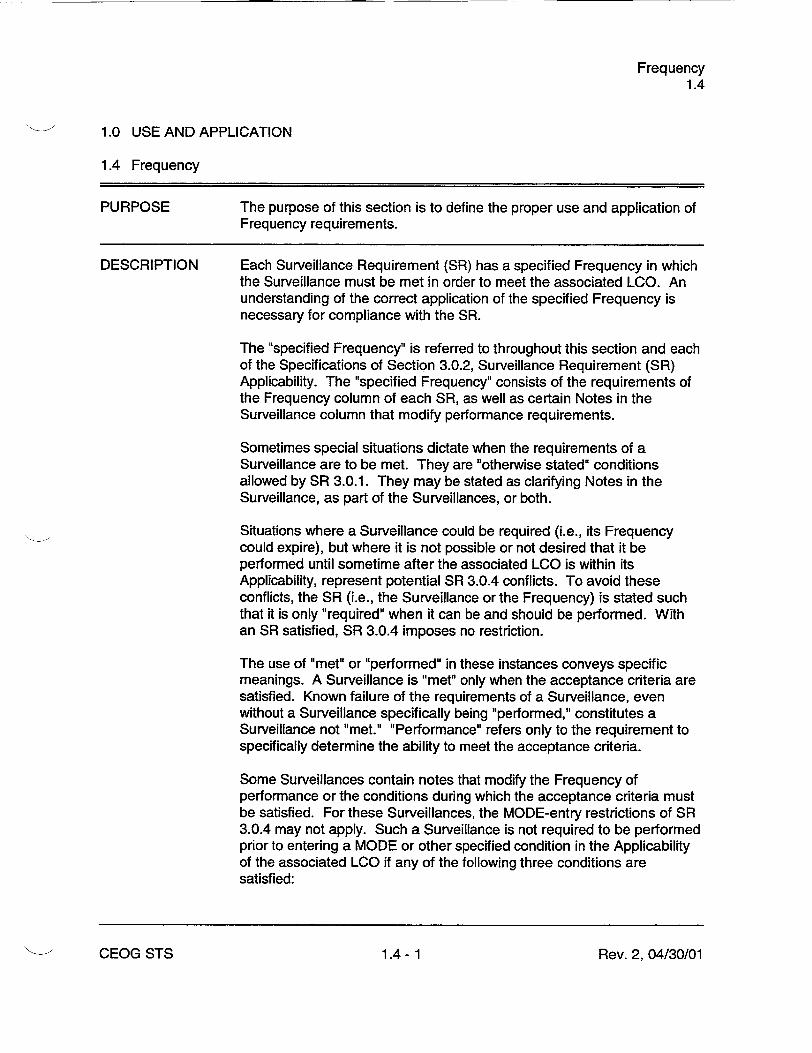
PURPOSE The purpose of this section is to define the proper use and application of Frequency requirements.
DESCRIPTION Each Surveillance Requirement (SR) has a specified Frequency in which the Surveillance must be met in order to meet the associated LCO. An understanding of the correct application of the specified Frequency is necessary for compliance with the SR.
The "specified Frequency" is referred to throughout this section and each of the Specifications of Section 3.0.2, Surveillance Requirement (SR) Applicability. The "specified Frequency" consists of the requirements of the Frequency column of each SR, as well as certain Notes in the Surveillance column that modify performance requirements.
Sometimes special situations dictate when the requirements of a Surveillance are to be met. They are "otherwise stated" conditions allowed by SR 3.0.1. They may be stated as clarifying Notes in the Surveillance, as part of the Surveillances, or both.
Situations where a Surveillance could be required (i.e., its Frequency could expire), but where it is not possible or not desired that it be performed until sometime after the associated LCO is within its Applicability, represent potential SR 3.0.4 conflicts. To avoid these conflicts, the SR (i.e., the Surveillance or the Frequency) is stated such that it is only "required" when it can be and should be performed. With an SR satisfied, SR 3.0.4 imposes no restriction.
The use of "met" or "performed" in these instances conveys specific meanings. A Surveillance is "met" only when the acceptance criteria are satisfied. Known failure of the requirements of a Surveillance, even without a Surveillance specifically being "performed," constitutes a Surveillance not "met." "Performance" refers only to the requirement to specifically determine the ability to meet the acceptance criteria.
Some Surveillances contain notes that modify the Frequency of performance or the conditions during which the acceptance criteria must be satisfied. For these Surveillances, the MODE-entry restrictions of SR 3.0.4 may not apply. Such a Surveillance is not required to be performed prior to entering a MODE or other specified condition in the Applicability of the associated LCO if any of the following three conditions are satisfied:
Rev. 2, 04/30/01CEOG STS 1.4- 1

Frequency 1.4
1.4 Frequency
DESCRIPTION (continued)
a. Fhe Surveillance is not required to be met in the MODE or other specified condition to be entered: or
b. The Surveillance is required to be met in the MODE or other specified condition to be entered, but has been performed within the specified Frequency (i.e., it is current) and is known not to be failed; or
c. The Surveillance is required to be met, but not performed, in the MODE or other specified condition to be entered, and is known no to be failed.
Examples 1.4-3, 1.4-4, 1.4-5, and 1.4-6 discusses these special situations.
EXAMPLES The following examples illustrate the various ways that Frequencies are specified. In these examples, the Applicability of the LCO (LCO not shown) is MODES 1, 2, and 3.
Rev. 2, 04/30/01CEOG STS 1.4- 2

Frequency 1.4
1.4 Frequency
EXAMPLES (continued)
EXAMPLE 1.4-1
SURVEILLANCE REQUIREMENTS
SURVEILLANCE FREQUENCY
Perform CHANNEL CHECK. 12 hours
Example 1.4-1 contains the type of SR most often encountered in the Technical Specifications (TS). The Frequency specifies an interval (12 hours) during which the associated Surveillance must be performed at least one time. Performance of the Surveillance initiates the subsequent interval. Although the Frequency is stated as 12 hours, an extension of the time interval to 1.25 times the stated Frequency is allowed by SR 3.0.2 for operational flexibility. The measurement of this interval continues at all times, even when the SR is not required to be met per SR 3.0.1 (such as when the equipment is inoperable, a variable is outside specified limits, or the unit is outside the Applicability of the LCO). If the interval specified by SR 3.0.2 is exceeded while the unit is in a MODE or other specified condition in the Applicability of the LCO, and the performance of the Surveillance is not otherwise modified (refer to Example 1.4-3), then SR 3.0.3 becomes applicable.
If the interval as specified by SR 3.0.2 is exceeded while the unit is not in a MODE or other specified condition in the Applicability of the LCO for which performance of the SR is required, the Surveillance must be performed within the Frequency requirements of SR 3.0.2 prior to entry into the MODE or other specified condition. Failure to do so would result in a violation of SR 3.0.4.
Rev. 2, 04/30/01CEOG STS 1.4- 3

Frequency 1.4
1.4 Frequency
EXAMPLES (continued)
EXAMPLE 1.4-2
SURVEILLANCE REQUIREMENTS
SURVEILLANCE FREQUENCY
Verify flow is within limits. Once within 12 hours after : 25% RTP
AND
24 hours thereafter
Example 1.4-2 has two Frequencies. The first is a one time performance Frequency, and the second is of the type shown in Example 1.4-1. The logical connector "AND" indicates that both Frequency requirements must be met. Each time reactor power is increased from a power level < 25% RTP to Ž 25% RTP, the Surveillance must be performed within 12 hours.
The Use of "once" indicates a single performance will satisfy the specified Frequency (assuming no other Frequencies are connected by "AND"). This type of Frequency does not qualify for the extension allowed by SR 3.0.2. "Thereafter' indicates future performances must be established per SR 3.0.2, but only after a specified condition is first met (i.e., the "once" performance in this example). If reactor power decreases to < 25% RTP, the measurement of both intervals stops. New intervals start upon reactor power reaching 25% RTP.
Rev. 2, 04/30/01CEOG STS 1.4- 4

Frequency 1.4
1.4 Frequency
EXAMPLES (continued)
EXAMPLE 1.4-3
SURVEILLANCE REQUIREMENTS
SURVEILLANCE FREQUENCY
- NOTENot required to be performed until 12 hours after : 25% RTP.
Perform channel adjustment. 7 days
The interval continues, whether or not the unit operation is < 25% RTP between performances.
As the Note modifies the required performance of the Surveillance, it is construed to be part of the "specified Frequency." Should the 7 day interval be exceeded while operation is < 25% RTP, this Note allows 12 hours after power reaches Ž 25% RTP to perform the Surveillance. The Surveillance is still considered to be performed within the "specified Frequency." Therefore, if the Surveillance were not performed within the 7 day (plus the extension allowed by SR 3.0.2) interval, but operation was < 25% RTP, it would not constitute a failure of the SR or failure to meet the LCO. Also, no violation of SR 3.0.4 occurs when changing MODES, even with the 7 day Frequency not met, provided operation does not exceed 12 hours with power Ž 25% RTP.
Once the unit reaches 25% RTP, 12 hours would be allowed for completing the Surveillance. If the Surveillance were not performed within this 12 hour interval, there would then be a failure to perform a Surveillance within the specified Frequency, and the provisions of SR 3.0.3 would apply.
Rev. 2, 04/30/01CEOG STS 1.4- 5

Frequency 1.4
1.4 Frequency
EXAMPLES (continued)
EXAMPLE 1.4-4
SURVEILLANCE REQUIREMENTS
SURVEILLANCE FREQUENCY
-NOTEOnly required to be met in MODE 1.
Verify leakage rates are within limits. 24 hours
Example 1.4.-4 specifies that the requirements of this Surveillance do not have to be met until the unit is in MODE 1. The interval measurement for the Frequency of this Surveillance continues at all times, as described in Example 1.4-1. However, the Note constitutes an "otherwise stated" exception to the Applicability of this Surveillance. Therefore, if the Surveillance were not performed within the 24 hour interval (plus the extension allowed by SR 3.0.2), but the unit was not in MODE 1, there would be no failure of the SR nor failure to meet the LCO. Therefore, no violation of SR 3.0.4 occurs when changing MODES, even with the 24 hour Frequency exceeded, provided the MODE change was not made into MODE 1. Prior to entering MODE 1 (assuming again that the 24 hour Frequency were not met), SR 3.0.4 would require satisfying the SR.
I.'-- o hev. 2, u4/3u0u1

Frequency 1.4
1.4 Frequency
EXAMPLES (continued)
EXAMPLE 1.4-5
SURVEILLANCE REQUIREMENTS
SURVEILLANCE FREQUENCY
- NOTE Only required to be performed in MODE 1.
Perform complete cycle of the valve. 7 days
The interval continues, whether or not the unit operation is in MODE 1,2 or 3 (the assumed Applicability of the associated LCO) between performances.
As the Note modifies the required performance of the Surveillance, the Note is construed to be part of the "specified Frequency." Should the 7 day interval be exceeded while operation is not in MODE 1, this Note allows entry into and operation in MODES 2 and 3 to perform the Surveillance. The Surveillance is still considered to be performed within the "specified Frequency" if completed prior to entering MODE 1. Therefore, if the Surveillance were not performed within the 7 day (plus the extension allowed by SR 3.0.2) interval, but operation was not in MODE 1, it would not constitute a failure of the SR or failure to meet the LCO. Also, no violation of SR 3.0.4 occurs when changing MODES, even with the 7 day Frequency not met, provided operation does not result in entry into MODE 1.
Once the unit reaches MODE 1, the requirement for the Surveillance to be performed within its specified Frequency applies and would require that the Surveillance had been performed. If the Surveillance were not performed prior to entering MODE 1, there would then be a failure to perform a Surveillance within the specified Frequency, and the provisions of SR 3.0.3 would apply.
Rev. 2, 04/30/01CEOG STS 1.4- 7

Frequency 1.4
1.4 Frequency
EXAMPLES (continued)
EXAMPLE 1.4-6
SURVEILLANCE REQUIREMENTS
SURVEILLANCE FREQUENCY
- NOTE Not required to be met in MODE 3.
Verify parameter is within limits. 24 hours
Example 1.4-[6] specifies that the requirements of this Surveillance do not have to be met while the unit is in MODE 3 (the assumed Applicability of the associated LCO is MODES 1,2, and 3). The interval measurement for the Frequency of this Surveillance continues at all times, as described in Example 1.4-1. However, the Note constitutes an "otherwise stated" exception to the Applicability of this Surveillance. Therefore, if the Surveillance were not performed within the 24 hour interval (plus the extension allowed by SR 3.0.2), and the unit was in MODE 3, there would be no failure of the SR nor failure to meet the LCO. Therefore, no violation of SR 3.0.4 occurs when changing MODES to enter MODE 3, even with the 24 hour Frequency exceeded, provided the MODE change does not result in entry into MODE 2. Prior to entering MODE 2 (assurming again that the 24 hour Frequency were not met), SR 3.0.4 would require satisfying the SR.
Rev. 2, 04/30/01CEOG STS 1.4- 8

SLs (Digital) 2.0
2.0 SAFETY LIMITS (SLs) (Digital)
2.1 SLs
2.1.1 Reactor Core SLs
2.1.1.1 In MODES 1 and 2, departure from nucleate boiling ratio (DNBR) shall be maintained at > [1.19].
2.1.1.2 In MODES 1 and 2, the peak linear heat rate (LHR) shall be maintained at _< [21.0] kW/ft.
2.1.2 Reactor Coolant System Pressure SL
In MODES 1, 2, 3, 4, and 5, the RCS pressure shall be maintained at _< [2750] psia.
2.2 SAFETY LIMIT VIOLATIONS
2.2.1 If SL 2.1.1.1 or SL 2.1.1.2 is violated, restore compliance and be in MODE 3 within 1 hour.
2.2.2 If SL 2.1.2 is violated:
2.2.2.1 In MODE 1 or 2, restore compliance and be in MODE 3 within 1 hour.
2.2.2.2 In MODE 3, 4, or 5, restore compliance within 5 minutes.
Rev. 2, 04/30/01CEOG STS 2.0- 1

600
UNACCEPTABLE OPERATION 580 UNACCEPTABLE
OPERATION
FOR PRE-CLAD COLLAPSE OPERATION ONLY
560 LIMITS CONTAIN NO ALLOWANCE 0 FOR INSTRUMENT ERROR OR FLUCTUATIONS
540 VALID FOR AXIAL SHAPES AND INTEGRATED ROD RADIAL PEAKING
FACTORS WITHIN LIMITS
520 REACTOR OPI-FATION LIMITED TO
< 500 0 F BY AC"UATION OF THE
SECONDARY SAFETY VALVES
500 I
FOR ILLUSTRATION ONLY. 194
L0DO NOT USE FOR OPERATION. 480 19
ACCEPTABLE OPERATION 1.8
60 !................0 0.2 0.4 0.6 0.8 1.0 1.2 1.4 1.6 1.8 2.0
FRACTION OF RATED THERMAL POWER
Figure 2.1.1-1 (page 1 of 1) Reactor Core Thermal Margin Safety Limit
Rev. 2, 04/30/01
SLs (Analog) 2.0
U
1,
a:E LU
LUJ
0
X
C-,
D-
4
CEOG STS 2.0 -2
LCO Applicability 3.0
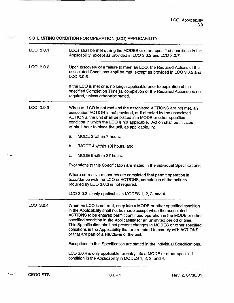
3.0 LIMITING CONDITION FOR OPERATION (LCO) APPLICABILITY
LCO 3.0.1 LCOs shall be met during the MODES or other specified conditions in the Applicability, except as provided in LCO 3.0.2 and LCO 3.0.7.
LCO 3.0.2 Upon discovery of a failure to meet an LCO, the Required Actions of the associated Conditions shall be met, except as provided in LCO 3.0.5 and LCO 3.0.6.
If the LCO is met or is no longer applicable prior to expiration of the specified Completion Time(s), completion of the Required Action(s) is not required, unless otherwise stated.
LCO 3.0.3 When an LCO is not met and the associated ACTIONS are not met, an associated ACTION is not provided, or if directed by the associated ACTIONS, the unit shall be placed in a MODE or other specified condition in which the LCO is not applicable. Action shall be initiated within 1 hour to place the unit, as applicable, in:
a. MODE 3 within 7 hours,
b. [MODE 4 within 13] hours, and
c. MODE 5 within 37 hours.
Exceptions to this Specification are stated in the individual Specifications.
Where corrective measures are completed that permit operation in accordance with the LCO or ACTIONS, completion of the actions required by LCO 3.0.3 is not required.
LCO 3.0.3 is only applicable in MODES 1, 2, 3, and 4.
LCO 3.0.4 When an LCO is not met, entry into a MODE or other specified condition in the Applicability shall not be made except when the associated ACTIONS to be entered permit continued operation in the MODE or other specified condition in the Applicability for an unlimited period of time. This Specification shall not prevent changes in MODES or other specified conditions in the Applicability that are required to comply with ACTIONS or that are part of a shutdown of the unit.
Exceptions to this Specification are stated in the individual Specifications.
LCO 3.0.4 is only applicable for entry into a MODE or other specified condition in the Applicability in MODES 1, 2, 3, and 4.
Rev. 2, 04/30/01CEOG STS 3.0- 1

LCO Applicability 3.0
3.0 LCO Applicability
LCO 3.0.4 (continued)
- REVIEWER'S NOTE LCO 3.0.4 has been revised so that changes in MODES or other specified conditions in the Applicability that are part of a shutdown of the unit shall not be prevented. In addition, LCO 3.0.4 has been revised so that it is only applicable for entry into a MODE or other specified condition in the Applicability in MODES 1, 2, 3, and 4. The MODE change restrictions in LCO 3.0.4 were previously applicable in all MODES. Before this version of LCO 3.0.4 can be implemented on a plant-specific basis, the licensee must review the existing technical specifications to determine where specific restrictions on MODE changes or Required Actions should be included in individual LCOs to justify this change; such an evaluation should be summarized in a matrix of all existing LCOs to facilitate NRC staff review of a conversion to the STS.
Equipment removed from service or declared inoperable to comply with ACTIONS may be returned to service under administrative control solely to perlorm testing required to demonstrate its OPERABILITY or the OPERABILITY of other equipment. This is an exception to LCO 3.0.2 for the system returned to service under administrative control to perform the testing required to demonstrate OPERABILITY.
When a supported system LCO is not met solely due to a support system LCO not being met, the Conditions and Required Actions associated with this supported system are not required to be entered. Only the support system LCO ACTIONS are required to be entered. This is an exception to LCO 3.0.2 for the supported system. In this event, an evaluation shall be performed in accordance with Specification 5.5.15, "Safety Function Determination Program (SFDP)." If a loss of safety function is determined to exist by this program, the appropriate Conditions and Required Actions of the LCO in which the loss of safety function exists are required to be entered.
When a support system's Required Action directs a supported system to be declared inoperable or directs entry into Conditions and Required Actions for a supported system, the applicable Conditions and Required Actions shall be entered in accordance with LCO 3.0.2.
Special test exception (STE) LCOs [in each applicable LCO section] allow specified Technical Specifications (TS) requirements to be changed to permit performance of special tests and operations. Unless otherwise specified, all other TS requirements remain unchanged. Compliance with
CEOG STS
LCO 3.0.5
LCO 3.0.6
LCO 3.0.7
3.0 -2 Rev. 2, 04/30/01

LCO Applicability 3.0
3.0 LCO Applicability
LCO 3.0.7 (continued)
STE LCOs is optional. When an STE LCO is desired to be met but is not met, the ACTIONS of the STE LCO shall be met. When an STE LCO is not desired to be met, entry into a MODE or other specified condition in the Applicability shall only be made in accordance with the other applicable Specifications.
Rev. 2, 04/30/013.0- 3CEOG STS

SR Applicability 3.0
3.0 SURVEILLANCE REQUIREMENT (SR) APPLICABILITY
SR 3.0.1 SRs shall be met during the MODES or other specified conditions in the Applicability for individual LCOs, unless otherwise stated in the SR. Failure to meet a Surveillance, whether such failure is experienced during the performance of the Surveillance or between performances of the Surveillance, shall be failure to meet the LCO. Failure to perform a Surveillance within the specified Frequency shall be failure to meet the LCO except as provided in SR 3.0.3. Surveillances do not have to be performed on inoperable equipment or variables outside specified limits.
SR 3.0.2 The specified Frequency for each SR is met if the Surveillance is performed within 1.25 times the interval specified in the Frequency, as measured from the previous performance or as measured from the time a specified condition of the Frequency is met.
For Frequencies specified as "once," the above interval extension does not apply.
If a Completion Time requires periodic performance on a "once per.. basis, the above Frequency extension applies to each performance after the initial performance.
Exceptions to this Specification are stated in the individual Specifications.
SR 3.0.3 If it is discovered that a Surveillance was not performed within its specified Frequency, then compliance with the requirement to declare the LCO riot met may be delayed, from the time of discovery, up to 24 hours or up to the limit of the specified Frequency, whichever is less. This delay period is permitted to allow performance of the Surveillance.
If the Surveillance is not performed within the delay period, the LCO must immediately be declared not met, and the applicable Condition(s) must be entered.
When the Surveillance is performed within the delay period and the Surveillance is not met, the LCO must immediately be declared not met, and the applicable Condition(s) must be entered.
SR 3.0.4 Entry into a MODE or other specified condition in the Applicability of an LCO shall not be made unless the LCO's Surveillances have been met within their specified Frequency. This provision shall not prevent entry into MODES or other specified conditions in the Applicability that are required to comply with ACTIONS or that are part of a shutdown of the unit.
Rev. 2, 04/30/01CEOG STS 3.0- 4

SR Applicability 3.0
3.0 SR Applicability
SR 3.0.4 (continued)
SR 3.0.4 is only applicable for entry into a MODE or other specified condition in the Applicability in MODES 1, 2, 3, and 4.
- REVIEWER'S NOTE SR 3.0.4 has been revised so that changes in MODES or other specified conditions in the Applicability that are part of a shutdown of the unit shall not be prevented. In addition, SR 3.0.4 has been revised so that it is only applicable for entry into a MODE or other specified condition in the Applicability in MODES 1, 2, 3, and 4. The MODE change restrictions in SR 3.0.4 were previously applicable in all MODES. Before this version of SR 3.0.4 can be implemented on a plant-specific basis, the licensee must review the existing technical specifications to determine where specific restrictions on MODE changes or Required Actions should be included in individual LCOs to justify this change; such an evaluation should be summarized in a matrix of all existing LCOs to facilitate NRC staff review of a conversion to the STS.
Rev. 2, 04/30/01CEOG STS 3.0- 5

SDM (Analog) 3.1.1
3.1 REACTIVITY CONTROL SYSTEMS
3.1.1 SHUTDOWN MARGIN (SDM) (Analog)
LCO 3.1.1
APPLICABILITY:
SHUTDOWN MARGIN (SDM) shall be within the limits specified in the COLR.
MODES 3, 4, and 5.
ACTIONS
CONDITION REQUIRED ACTION COMPLETION TIME
A. SDM not within limits. A.1 Initiate boration to restore 15 minutes SDM to within limits.
SURVEILLANCE REQUIREMENTS
SURVEILLANCE FREQUENCY
SR 3.1.1.1 Verify SDM to be within limits. 24 hours
Rev. 2, 04/30/01CEOG STS 3.1.1- 1

Reactivity Balance (Analog) 3.1.2
3.1 REACTIVITY CONTROL SYSTEMS
3.1.2 Reactivity Balance (Analog)
LCO 3.1.2
APPLICABILITY:
The core reactivity balance shall be within ± 1 % Ak/k of predicted values.
MODES 1 and 2.
ACTIONS
CONDITION REQUIRED ACTION COMPLETION TIME
A. Core reactivity balance A.1 Re-evaluate core design 7 days not within limit, and safety analysis and
determine that the reactor core is acceptable for continued operation.
AND
A.2 Establish appropriate 7 days operating restrictions and SRs.
B. Required Action and B.1 Be in MODE 3. 6 hours associated Completion Time not met.
Rev. 2, 04/30/01CEOG STS 3.1.2- 1

Reactivity Balance (Analog) 3.1.2
SURVEILLANCE REQUIREMENTS
"SURVEILLANCE FREQUENCY
S R 3 .1 .2 .1 ----------.. ---------------------------------- . . . . . . . . . - NOTES
1. The predicted reactivity values may be adjusted (normalized) to correspond to the measured core reactivity prior to exceeding a fuel burnup of 60 effective full power days (EFPD) after each fuel loading.
2. This Surveillance is not required to be perfor-med prior to entry into MODE 2.
Verify overall core reactivity balance is within Prior to entering _ 1.0% Ak/k of predicted values. MODE 1 after fuel
loading
AND
- NOTE Only required after 60 EFPD
31 EFPDI _________________________________________________________
Rev. 2, 04/30/01CEOG STS 3.1.2- 2

MTC (Analog) 3.1.3
3.1 REACTIVITY CONTROL SYSTEMS
3.1.3 Moderator Temperature Coefficient (MTC) (Analog)
LCO 3.1.3
APPLICABILITY:
The Moderator Temperature Coefficient (MTC) shall be maintained within the limits specified in the COLR. The maximum positive limit shall be that specified in Figure 3.1.3-1.
MODES 1 and 2.
ACTIONS
CONDITION REQUIRED ACTION COMPLETION TIME
A. MTC not within limits. A.1 Be in MODE 3. 6 hours
SURVEILLANCE REQUIREMENTS
SURVEILLANCE FREQUENCY
SR 3.1.3.1 Verify MTC is within the upper limit. Prior to entering MODE 1 after each fuel loading
Rev. 2, 04/30/01"-• CEOG STS 3.1.3- 1

MTC (Analog) 3.1.3
SURVEILLANVE REQUIREMENTS (continued)
SURVEILLANCE FREQUENCY
S R 3 .1 .3 .2 -------------------------------------------------------- NOTES
1. This Surveillance is not required to be performed prior to entry into MODE 1 or 2.
2. If the MTC is more negative than the COLR limit when extrapolated to the end of cycle, SR 3.1.3.2 may be repeated. Shutdown must occur prior to exceeding the minimum allowable boron concentration at which MTC is projected to exceed the lower limit.
Verify MTC is within the lower limit. Each fuel cycle within 7 effective full power days (EFPD) of reaching 40 EFPD core burnup
AND
Each fuel cycle within 7 EFPD of reaching 2/3 of expected core burnup
______________________________________________________________________ .5 ____________________________________________________
Rev. 2, 04/30/01CEOG STS 3.1.3-2

MTC (Analog) 3.1.3
FOR ILLUSTRATION ONLY.|1
DO NOT USE FOR OPERATION.ý
UNACCEPTABLE OPERATION REGION
POSITIVE MTC LIMIT LINE
Z- 770 0 71
U
CD
LL
W
0
I
LLI
-j
0
0
-. I
0 -_1 ACCEPTABLE OPERATION REGION
I I I I I I I
10 20 30 40 50 60 70 80 90 100
PERCENT OF RTP
Figure 3.1.3-1 (page 1 of 1) Allowable Positive MTC Limit
Rev. 2, 04/30/01
1.0
0.9
0.8
0.7
0.6
0.5
(100,0.3)
0.4k
0.3
0.2 -
0.1
0.00
-- .i v o
CEOG STS 3.1.3- 3

CEA Alignment (Analog) 3.1.4
3.1 REACTIVITY CONTROL SYSTEMS
3.1.4 Control Element Assembly (CEA) Alignment (Analog)
LCO 3.1.4 All Control Element Assemblies (CEAs) shall be OPERABLE and aligned to within [7] inches (indicated position) of their respective group, and [the CEA motion inhibit and the CEA deviation circuit shall be OPERABLE].
APPLICABILITY: MODES 1 and 2.
ACTIONS
CONDITION REQUIRED ACTION COMPLETION TIME
A. One or more CEAs A.1 Reduce THERMAL 1 hour trippable and misaligned POWER to _ 70% RTP. from its group by > [7 inches] and AND _ [15 inches].
A.2 Restore CEA Alignment. 2 hours OR
One CEA trippable and misaligned from its group by > [15 inches].
B. CEA motion inhibit B.1 Perform SR 3.1.4.1. 1 hour inoperable.
AND
Every 4 hours
thereafter
AND
B.2.1 Restore CEA motion 6 hours inhibit to OPERABLE status.
OR
Rev. 2, 04/30/01CEOG STS 3.1.4- 1

CEA Alignment (Analog) 3.1.4
ACTIONS (continued)
CONDITION REQUIRED ACTION COMPLETION TIME
B.2.2 ---------------------------
- NOTE Required Action B.2.2 shall not be performed when in conflict with either Required Action A.1, A.2, or C.1.
Place and maintain the 6 hours CEA drive switch in either the "off" or "manual" position, [and fully withdraw all CEAs in groups 3 and 4 and withdraw all CEAs in group 5 to < 5% insertion].
C. CEA deviation circuit C.1 Perform SR 3.1.4.1. 1 hour inoperable.
AND
Every 4 hours thereafter
D. Required Action and D.1 Be in MODE 3. 6 hours associated Completion Time not met.
OR
One or more CEAs untrippable.
OR
Two or more CEAs misaligned by > [15 inches].
CEOG STS Rev. 2, 04/30/013.1.4- 2

CEA Alignment (Analog) 3.1.4
SURVEILLANCE REQUIREMENTS
SURVEILLANCE FREQUENCY
SR 3.1.4.1 Verify the indicated position of each CEA to be within Within 1 hour [7 inches] of all other CEAs in its group. Following any
movement of > [7 inches]
AND
12 hours
SR 3.1.4.2 Verify the CEA motion inhibit is OPERABLE. 92 days
SR 3.1.4.3 Verify the CEA deviation circuit is OPERABLE. 31 days
SR 3.1.4.4 Verify CEA freedom of movement (trippability) by 92 days moving each individual CEA that is not fully inserted into the reactor core [5 inches] in either direction.
SR 3.1.4.5 Perform a CHANNEL FUNCTIONAL TEST of the 18 months reed switch position transmitter channel.
SR 3.1.4.6 Verify each CEA drop time is • [3.1] seconds. Prior to reactor criticality, after each removal of the reactor head
Rev. 2, 04/30/01CEOG STS 3.1.4- 3

Shutdown CEA Insertion Limits (Analog) 3.1.5
3.1 REACTIVITY CONTROL SYSTEMS
3.1.5 Shutdown Control Element Assembly (CEA) Insertion Limits (Analog)
LCO 3.1.5
APPLICABILITY:
All shutdown Control Element Assemblies (CEAs) shall be withdrawn to Ž [129] inches.
MODE 1, MODE 2 with any regulating CEA not fully inserted.
ACTIONS
- NOTE This LCO is not applicable while performing SR 3.1.4.5.
CONDITION REQUIRED ACTION COMPLETION TIME
A. One or more shutdown A.1 Restore shutdown CEA(s) 2 hours CEAs not within limit, to within limit.
B. Required Action and B.1 Be in MODE 3. 6 hours associated Completion Time not met.
SURVEILLANCE REQUIREMENTS
SURVEILLANCE FREQUENCY
SR 3.1.5.1 Verify each shutdown CEA is withdrawn 12 hours Ž [129] inches.
Rev. 2, 04/30/01CEOG STS 3.1.5- 1

Regulating CEA Insertion Limits (Analog) 3.1.6
3.1 REACTIVITY CONTROL SYSTEMS
3.1.6 Regulating Control Element Assembly (CEA) Insertion Limits (Analog)
LCO 3.1.6
APPLICABILITY:
The power dependent insertion limit (PDIL) alarm circuit shall be OPERABLE, and the regulating Control Element Assembly (CEA) groups shall be limited to the withdrawal sequence and to the insertion limits specified in the COLR.
MODES 1 and 2.
ACTIONS
- NOTE This LCO is not applicable while performing SR 3.1.4.5 [or during reactor power cutback operation].
CONDITION REQUIRED ACTION COMPLETION TIME
A. Regulating CEA groups A.1 Restore regulating CEA 2 hours inserted beyond the groups to within limits. transient insertion limit.
OR
A.2 Reduce THERMAL 2 hours POWER to less than or equal to the fraction of RTP allowed by the CEA group position and insertion limits specified in the COLR.
B. Regulating CEA groups B.1 Verify short term steady 15 minutes inserted between the state insertion limits are long term steady state not exceeded. insertion limit and the transient insertion limit OR for > 4 hours per 24 hour interval.
Rev. 2, 04/30/013.1.6- 1CEOG STS
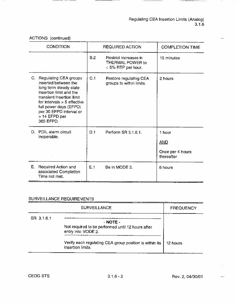
Regulating CEA Insertion Limits (Analog) 3.1.6
ACTIONS (continued)
CONDITION REQUIRED ACTION COMPLETION TIME
B.2 Restrict increases in 15 minutes THERMAL POWER to •< 5% RTP per hour.
C. Regulating CEA groups C.1 Restore regulating CEA 2 hours inserted between the groups to within limits. long term steady state insertion limit and the transient insertion limit for intervals > 5 effective full power days (EFPD') per 30 EFPD interval or > 14 EFPD per 365 EFPD.
D. PDIL alarm circuit D.1 Perform SR 3.1.6.1. 1 hour inoperable.
AND
Once per 4 hours thereafter
E. Required Action and E.1 Be in MODE 3. 6 hours associated Completion Time not met.
SURVEILLANCE REQUIREMENTS
SURVEILLANCE FREQUENCY
S R 3 .1 .6 .1 ------------------------------------------------------ NOTE
Not required to be performed until 12 hours after entry into MODE 2.
Verify each regulating CEA group position is within its 12 hours insertion limits.
Rev. 2, 04/30/01CEOG STS 3.1.6- 2

Regulating CEA Insertion Limits (Analog) 3.1.6
SURVEILLANCE REQUIREMENTS (continued)
SURVEILLANCE FREQUENCY
SR 3.1.6.2 Verify the accumulated times during which the 24 hours regulating CEA groups are inserted beyond the steady state insertion limits but within the transient insertion limits.
SR 3.1.6.3 Verify PDIL alarm circuit is OPERABLE. 31 days
Rev. 2, 04/30/01CEOG STS 3.1.6- 3
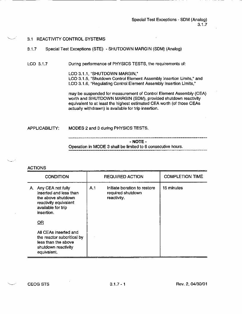
Special Test Exceptions - SDM (Analog) 3.1.7
3.1 REACTIVITY CONTROL SYSTEMS
3.1.7 Special Test Exceptions (STE) - SHUTDOWN MARGIN (SDM) (Analog)
During performance of PHYSICS TESTS, the requirements of:
LCO 3.1.1, "SHUTDOWN MARGIN," LCO 3.1.5, "Shutdown Control Element Assembly Insertion Limits," and LCO 3.1.6, "Regulating Control Element Assembly Insertion Limits,"
may be suspended for measurement of Control Element Assembly (CEA) worth and SHUTDOWN MARGIN (SDM), provided shutdown reactivity equivalent to at least the highest estimated CEA worth (of those CEAs actually withdrawn) is available for trip insertion.
APPLICABILITY: MODES 2 and 3 during PHYSICS TESTS.
- NOTE Operation in MODE 3 shall be limited to 6 consecutive hours.
ACTIONS
CONDITION REQUIRED ACTION COMPLETION TIME
A. Any CEA not fully A.1 Initiate boration to restore 15 minutes inserted and less than required shutdown the above shutdown reactivity. reactivity equivalent available for trip insertion.
OR
All CEAs inserted and the reactor subcritical by less than the above shutdown reactivity equivalent.
Rev. 2, 04/30/01
LCO 3.1.7
CEOG STS 3.1.7- 1

Special Test Exceptions - SDM (Analog) 3.1.7
SURVEILLANCE REQUIREMENTS
SURVEILLANCE FREQUENCY
SR 3.1.7.1 Verify that the position of each CEA not fully inserted 2 hours is within Ihe acceptance criteria for available negative reactivity addition.
S R 3 .1 .7 .2 ------------------------------------------------------ NOTE
Not required to be performed during initial power escalation following a refueling outage if SR 3.1.5.7 has been met. --------------------------------------
Verify that each CEA not fully inserted is capable of Once within full insertion when tripped from at least the 50% [7 days] prior to withdrawn position. reducing SDM to
less than the limits of LCO 3.1.1
CEOG STS 3.1.7- 2 Rev. 2, 04/30/01

Special Test Exceptions - MODES 1 and 2 (Analog) 3.1.8
3.1 REACTIVITY CONTROL SYSTEMS
3.1.8 Special Test Exceptions (STE) - MODES 1 and 2 (Analog)
During the performance of PHYSICS TESTS, the requirements of:
LCO 3.1.3, LCO 3.1.4, LCO 3.1.5, LCO 3.1.6, LCO 3.2.2, LCO 3.2.3, LCO 3.2.4,
"Moderator Temperature Coefficient," "Control Element Assembly Alignmen," "Shutdown Control Element Assembly Insertion Limits," "Regulating Control Element Assembly Insertion Limits," "Total Planar Radial Peaking Factor," "Total Integrated Radial Peaking Factor," and "AZIMUTHAL POWER TILT,"
may be suspended, provided THERMAL POWER is restricted to the test power plateau, which shall not exceed 85% RTP.
APPLICABILITY: MODES 1 and 2 during PHYSICS TESTS.
ACTIONS
CONDITION REQUIRED ACTION COMPLETION TIME
A. Test power plateau A.1 Reduce THERMAL 15 minutes exceeded. POWER to less than or
equal to test power plateau.
B. Required Action and B.1 Suspend PHYSICS 1 hour associated Completion TESTS. Time not met.
SURVEILLANCE REQUIREMENTS
SURVEILLANCE FREQUENCY
SR 3.1.8.1 Verify THERMAL POWER is equal to or less than the 1 hour test power plateau.
Rev. 2, 04/30/01
LCO 3.1.8
3.1.8- 1CEOG STS

Special Test Exception - SDM (Digital) 3.1.8
SURVEILLANCE REQUIREMENTS
SURVEILLANCE FREQUENCY
SR 3.1.8.1 Verify that the position of each CEA not fully inserted 2 hours is within the acceptance criteria for available negative reactivity addition.
S R 3 .1 .8 .2 ------------------------------------------------------ NOTE
Not required to be performed during initial power escalation following a refueling outage if SR 3.1.4.5 has been met.
Verify each full length CEA not fully inserted is Once within capable o- full insertion when tripped from at least the [7 days] prior to 50% withdrawn position. reducing SDM to
less than the limits of LCO 3.1.1
CEOG STS 3.1.8- 2 Rev. 2, 04/30/01

LHR (Analog) 3.2.1
3.2 POWER DISTRIBUTION LIMITS
3.2.1 Linear Heat Rate (LHR) (Analog)
LCO 3.2.1
APPLICABILITY:
LHR shall not exceed the limits specified in the COLR.
MODE 1.
ACTIONS
CONDITION REQUIRED ACTION COMPLETION TIME
A. LHR, as determined by A.1 Restore LHR to within 1 hour the Incore Detector limits. Monitoring System, exceeds the limits specified in the COLR, as indicated by four or more coincident incore channels.
OR
LHR, as determined by the Excore Detector Monitoring System, exceeds the limits as indicated by the ASI outside the power dependent control limits specified in the COLR.
B. Required Action and B.1 Be in MODE 2. 6 hours associated Completion Time not met.
Rev. 2, 04/30/01CEOG STS 3.2.1- 1

LHR (Analog) 3.2.1
SURVEILLANCE REQUIREMENTS
- NOTE Either the Excore Detector Monitoring System or the Incore Detector Monitoring System shall be used to determine LHR.
SURVEILLANCE FREQUENCY
SR 3.2.1.1 --- ----------------------------------------------------
- NOTEOnly required to be met when the Excore Detector Monitoring System is being used to determine LHR.
Verify ASI alarm setpoints are within the limits 31 days specified in the COLR.
SR 3.2.1.2 - NOTES
1. Only required to be met when the Incore Detector Monitoring System is being used to determine LHR.
2. Not required to be performed below 20% RTP.
Verify imoore detector local power density alarms 31 days satisfy the requirements of the core power distribution map, which shall be updated at least once per 31 days of accumulated operation in MODE 1.
S R 3 .2 .1 .3 ------------------------------------------------------ NOTES
1. Only required to be met when the Incore Detector Monitoring System is being used to determine LHR.
2. Not required to be performed below 20% RTP.
Verify incore detector local power density alarm 31 days setpoints are less than or equal to the limits specified in the COLR.
Rev. 2, 04/30/01CEOG STS 3.2.1- 2

FT (Analog) 3.2.2
3.2 POWER DISTRIBUTION LIMITS
3.2.2 Total Planar Radial Peaking Factor (FT) (Analog)
LCO 3.2.2
APPLICABILITY:
The calculated value of F.T shall not exceed the limits specified in the COLR.
MODE 1.
ACTIONS
CONDITION REQUIRED ACTION COMPLETION TIME
A. -------------------- A.1 Reduce THERMAL 6 hours - NOTE - POWER to bring the
Required Actions shall combination of THERMAL be completed if this POWER and Fm to within Condition is entered. the limits specified in the
COLR. FT not within limits.
AND
A.2 Withdraw the control 6 hours element assemblies (CEAs) to or beyond the long term steady state insertion limits of LCO 3.1.6, "Regulating CEAs," as specified in the COLR.
B. Required Action and B.1 Be in MODE 2. 6 hours associated Completion Time not met.
Rev. 2, 04/30/01CEOG STS 3.2.2- 1

F, (Analog) 3.2.2
SURVEILLANCE REQUIREMENTS
SURVEILLANCE
SR 3.2.2.1- NOTE
SR 3.2.2.;2 and SR 3.2.2.3 shall be completed each time SR 3.2.2.1 is required. FT shall be determined by using the incore detectors to obtain a power distribution map with all full length CEAs at or above the long term steady state insertion limit, as specified in the COLR.
Verify the value of FTj.
Ir
FREQUENCYi1
Once prior to operation above 70% RTP after each fuel loading
AND
Each 31 days of accumulated operation in MODE 1
SR 3.2.2.2 Verify the value of Fxy. In accordance with the Frequency requirements of SR 3.2.2.1
SR 3.2.2.3 Verify the value of Tq. In accordance with the Frequency requirements of SR 3.2.2.1
Rev. 2, 04/30/01CEOG STS 3.2.2- 2

FrT (Analog) 3.2.3
3.2 POWER DISTRIBUTION LIMITS
3.2.3 Total Integrated Radial Peaking Factor (Fr) (Analog)
LCO 3.2.3
APPLICABILITY:
The calculated value of Frshall be within the limits specified in the COLR.
MODE 1.
ACTIONS
CONDITION REQUIRED ACTION COMPLETION TIME
A. --------------------- A.1 Reduce THERMAL 6 hours - NOTE - POWER to bring the
Required Actions shall combination of THERMAL be completed if this POWER and Fmto within Condition is entered. limits specified in the
COLR. F Tnot within limit.
AND
A.2 Withdraw the control 6 hours element assemblies (CEAs) to or beyond the long term steady state insertion limits of LCO 3.1.6, "Regulating Control Element Assembly (CEA) Insertion Limits," as specified in the COLR.
AND
A.3 Establish a revised upper 6 hours THERMAL POWER limit as specified in the COLR.
B. Required Actions and B.1 Be in MODE 2. 6 hours associated Completion Times not met.
Rev. 2, 04/30/01CEOG STS 3.2.3- 1
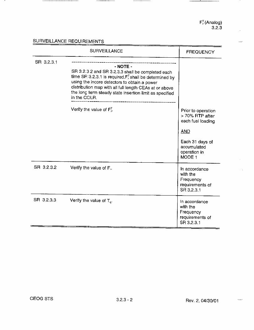
FrT (Analog) 3.2.3
SURVEILLANCE REQUIREMENTS
SURVEILLANCE
SR 3.2.3.1- NOTE
SR 3.2.3.2 and SR 3.2.3.3 shall be completed each time SR 3.2.3.1 is required.FTshall be determined by using the incore detectors to obtain a power distribution map with all full length CEAs at or above the long lerm steady state insertion limit as specified in the CC',LR.
Verify the value of FrT
FREQUENCY
Prior to operation > 70% RTP after each fuel loading
AND
Each 31 days of accumulated operation in MODE 1
SR 3.2.3.2 Verify the value of Fr. In accordance with the Frequency requirements of SR 3.2.3.1
SR 3.2.3.3 Verify the value of Tq. In accordance with the Frequency requirements of SR 3.2.3.1
CEOG STS Rev. 2, 04/30/01
I
3.2.3- 2
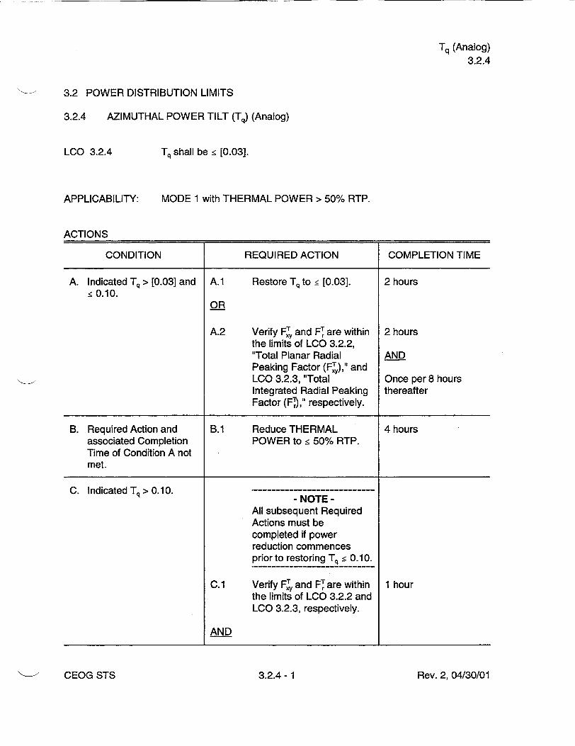
Tq (Analog) 3.2.4
3.2 POWER DISTRIBUTION LIMITS
3.2.4 AZIMUTHAL POWER TILT (Tq) (Analog)
LCO 3.2.4
APPLICABILITY:
Tq shall be _< [0.03].
MODE 1 with THERMAL POWER > 50% RTP.
ACTIONS
CONDITION REQUIRED ACTION COMPLETION TIME
A. Indicated Tq > [0.03] and A.1 Restore Tq to _< [0.03]. 2 hours <0.10.
OR
A.2 Verify F, and FT are within 2 hours the limits of LCO 3.2.2, "Total Planar Radial AND Peaking Factor (FT)," and LCO 3.2.3, "Total Once per 8 hours Integrated Radial Peaking thereafter Factor (FT),' respectively.
B. Required Action and B.1 Reduce THERMAL 4 hours associated Completion POWER to _< 50% RTP. Time of Condition A not met.
C. Indicated Tq >0.10. - NOTE
All subsequent Required Actions must be completed if power reduction commences prior to restoring Tq _< 0.10.
C.1 Verify FT and FT, are within 1 hour the limits of LCO 3.2.2 and LCO 3.2.3, respectively.
AND
Rev. 2, 04/30/01"• ~CEOG STS 3.2.4- 1

Tq (Analog)
3.2.4
ACTIONS (continued)
CONDITION REQUIRED ACTION COMPLETION TIME
C.2 Reduce THERMAL 2 hours POWER to < 50% RTP.
AND
C.3 Restore Tq to < [0.03]. Correct the cause of the out of limit condition prior to increasing THERMAL POWER. Subsequent power operation above 50% RTP may proceed provided that the measured Tq is verified _ [0.03] at least once per hours for 12 hours, or until verified at 95% RTP.
SURVEILLANCE REQUIREMENTS
Rev. 2, 04/30/01CEOG STS 3.2.4- 2

ASI (Analog) 3.2.5
3.2 POWER DISTRIBUTION LIMITS
3.2.5 AXIAL SHAPE INDEX (ASI) (Analog)
LCO 3.2.5
APPLICABILITY:
The ASI shall be maintained within the limits specified in the COLR.
MODE 1 with THERMAL POWER > 20% RTP.
ACTIONS
CONDITION REQUIRED ACTION COMPLETION TIME
A. ASI not within limits. A.1 Restore ASI to within 2 hours limits.
B. Required Action and B.1 Reduce THERMAL 4 hours associated Completion POWER to _< 20% RTP. Time not met.
SURVEILLANCE REQUIREMENTS
SURVEILLANCE FREQUENCY
SR 3.2.5.1 Verify ASI is within limits specified in the COLR. 12 hours
Rev. 2, 04/30/01CEOG STS 3.2.5- 1

RPS Instrumentation - Operating (Analog) 3.3.1
3.3 INSTRUMENTATION
3.3.1 Reactor Protective System (RPS) Instrumentation - Operating (Analog)
LCO 3.3.1 Four RPS trip units and associated instrument and bypass removal channels for each Function in Table 3.3.1-1 shall be OPERABLE.
APPLICABILITY: According to Table 3.3.1-1.
ACTIONS
- NOTE Separate Condition entry is allowed for each RPS Function.
CONDITION REQUIRED ACTION COMPLETION TIME
A. One or more Functions A.1 Place affected trip unit in 1 hour with one RPS trip unit or bypass or trip. associated instrument channel inoperable AND except for Condition C (excore channel not A.2.1 Restore channel to [48] hours calibrated with incore OPERABLE status. detectors).
OR
A.2.2 [Place affected tripunit in 48 hours] trip.
B. One or more Functions -----....... with two RPS trip units - NOTE
or associated instrument LCO 3.0.4 is not
channels inoperable applicable. except for Condition C (excore channel not B.1 Place one trip unit in 1 hour calibrated with incore bypass and place the detectors). other trip unit in trip.
AND
B.2 Restore one trip unit to [48] hours OPERABLE status.
Rev. 2, 04/30/01CEOG STS 3.3.1- 1

RPS Instrumentation - Operating (Analog) 3.3.1
ACTIONS (continued)
CONDITION REQUIRED ACTION COMPLETION TIME
C. One or more Functions C.1 Perform SR 3.3.1.3. 24 hours with one or more power range excore channels OR not calibrated with the incore detectors. C.2 Restrict THERMAL 24 hours
POWER to _< 90% RTP.
D. One or more Functions D.1 Disable bypass channel. 1 hour with one automatic bypass removal channel OR inoperable.
D.2.1 Place affected trip units in 1 hour bypass or trip.
AND
D.2.2.1 Restore bypass removal [48] hours channel and affected trip units to OPERABLE status.
OR
D.2.2.2 [ Place affected trip units in 48 hours ] trip.
E. One or more Functions with two automatic - NOTE bypass removal LCO 3.0.4 is not channels inoperable, applicable.
E.1 Disable bypass 1 hour channels.
OR
Rev. 2, 04/30/01CEOG STS 3.3.1 -2

RPS Instrumentation - Operating (Analog) 3.3.1
ACTIONS (continued)
CONDITION REQUIRED ACTION COMPLETION TIME
E.2.1 [ Place one affected trip unit 1 hour in bypass and place the other in trip for each affected trip Function.
AND
E.2.2 Restore one automatic [48] hours] bypass removal channel and the associated trip unit to OPERABLE status for each affected trip Function.
F. Required Action and F.1 Reduce THERMAL 6 hours associated Completion POWER to < 15% RTP. Time not met for Axial Power Distribution and Loss of Load Trip Functions.
G. Required Action and G.1 Be in MODE 3. 6 hours associated Completion Time not met except for Axial Power Distribution or Loss of Load Trip Functions.
SURVEILLANCE REQUIREMENTS
- NOTE Refer to Table 3.3.1-1 to determine which SR shall be performed for each RPS Function.
SURVEILLANCE FREQUENCY
SR 3.3.1.1 Perform a CHANNEL CHECK of each RPS 12 hours instrument channel except Loss of Load.
Rev. 2, 04/30/01CEOG STS 3.3.1- 3

RPS Instrumentation - Operating (Analog) 3.3.1
SURVEILLANCE REQUIREMENTS (continued)
SURVEILLANCE
SR 3.3.1.2- NOTES
1. Not required to be performed until 12 hours after THERMAL POWER is > [20]% RTP.
2. The daily calibration may be suspended during PHYSICS TESTS, provided the calibration is perfo-med upon reaching each major test power plateau and prior to proceeding to the next major test power plateau.
Perform calibration (heat balance only) and adjust the excore power range and AT power channels to agree with calorimetric calculation if the absolute difference is > [1.5]%.
FREQUENCY
24 hours
SR 3.3.1.3 -- ----------------------------------------------------- NOTE
Not required to be performed until 12 hours after THERMAL POWER is Ž [201% RTP.
Calibrate the power range excore channels using the 31 days incore detectors.
SR 3.3.1.4 Perform a CHANNEL FUNCTIONAL TEST of each [92] days RPS channel except Loss of Load and Power Rate of Change.
SR 3.3.1.5 -- ------------------------------------------------------ NOTE
Neutron detectors are excluded from CHANNEL CALIBRATION. ----------------------------------------
Perform a CHANNEL CALIBRATION on excore 92 days power range channels.
SR 3.3.1.6 Perform a CHANNEL FUNCTIONAL TEST of each Once within Power Rate of Change channel and each Loss of 7 days prior to Load functional unit. each reactor
startup
Rev. 2, 04/30/01
I
CEOG STS 3.3.1- 4

RPS Instrumentation - Operating (Analog) 3.3.1
SURVEILLANCE REQUIREMENTS (continued)
SURVEILLANCE FREQUENCY
SR 3.3.1.7 Perform a CHANNEL FUNCTIONAL TEST on each Once within automatic bypass removal function. 92 days prior to
each reactor startup
SR 3.3.1.8 -NOTE
Neutron detectors are excluded from CHANNEL CALIBRATION.
Perform a CHANNEL CALIBRATION of each RPS [18] months instrument channel, including bypass removal functions.
SR 3.3.1.9 - NOTE
Neutron detectors are excluded from RPS RESPONSE TIME testing.
Verify RPS RESPONSE TIME is within limits. [18] months on a STAGGERED TEST BASIS
Rev. 2, 04/30/01CEOG STS 3.3.1 - 5

RPS Instrumentation - Operating (Analog) 3.3.1
Table 3.3.1-1 (page 1 of 2) Reactor Protective System Instrumentation
APPLICABLE MODES OR OTHER SPECIFIED SURVEILLANCE
FUNCTION CONDITIONS REQUIREMENTS ALLOWABLE VALUE
1. Variable High 1,2 SR 3.3.1.1 • [10]% RTP above current Power Trip SR 3.3.1.2 THERMAL POWER but not
SR 3.3.1.3 < [30]% RTP nor SR 3.3.1.4 > [107]% RTP SR 3.3.1.5 SR 3.3.1.8 SR 3.3.1.9
2. Power Rate of 1,2 SR 3.3.1.1 ! [2.6] dpm Change - High(a) SR 3.3.1.6
SR 3.3.1.7 SR 3.3.1.8
3. Reactor Coolant 1,2 SR 3.3.1.1 Ž [95]% Flow - Low(b) SR 3.3.1.4
SR 3.3.1.7 SR 3.3.1.8 SR 3.3.1.9
4. Pressurizer 1,2 SR 3.3.1.1 • [2400] psia Pressure - High SR 3.3.1.4
SR 3.3.1.8 SR 3.3.1.9
5. Containment 1,2 [SR 3.3.1.1] • [4.0] psig Pressure - High SR 3.3.1.4
SR 3.3.1.8 SR 3.3.1.9
6. Steam Generatpr 1,2 SR 3.3.1.1 Ž [685] psia Pressure - Low") SR 3.3.1.4
SR 3.3.1.7 SR 3.3.1.8 SR 3.3.1.9
(a) Trip may be bypassed when THERMAL POWER is < [1 E-4]% RTP or > [13]% RTP. Bypass shall be automatically removed when THERMAL POWER is Ž [1E-4]% RTP and • [13]% RTP.
(b) Trips may be bypassed when THERMAL POWER is < [1 E-4]%. Bypass shall be automatically removed when THERMAL POWER is 2 [1 E-41% RTP. During testing pursuant to LCO 3.4.17, RCS Loops - Test Exceptions, trips may be bypassed below 5% RTP. Bypass shall be automatically removed when THERMAL POWER is Ž 5% RTP.
(c) Trip may be bypassed when steam generator pressure is < [785] psig. Bypass shall be automatically removed when steam generator pressure is > [785] psig.
Rev. 2, 04/30/01CEOG STS 3.3.1- 6

RPS Instrumentation - Operating (Analog) 3.3.1
Table 3.3.1-1 (page 1 of 2) Reactor Protective System Instrumentation
APPLICABLE MODES OR OTHER SPECIFIED SURVEILLANCE
FUNCTION CONDITIONS REQUIREMENTS ALLOWABLE VALUE
7a. Steam Generator A 1,2 SR 3.3.1.1 Ž [24.7]% Level - Low SR 3.3.1.4
SR 3.3.1.8 SR 3.3.1.9
7b. Steam Generator 1,2 SR 3.3.1.1 > [24.7]% B Level - Low SR 3.3.1.4
SR 3.3.1.8 SR 3.3.1.9
[8. Axial Power 1 (d) (e) SR 3.3.1.1 Figure 3.3.1-3] Distribution - SR 3.3.1.2
SR 3.3.1.3 SR 3.3.1.4 SR 3.3.1.5 SR 3.3.1.7 SR 3.3.1.8 SR 3.3.1.9
9a. Thermal 1,2 SR 3.3.1.1 Figures 3.3.1-1 and 3.3.1-2 Margin/Low SR 3.3.1.2 Pressure SR 3.3.1.3 (TM/LP)() SR 3.3.1.4
SR 3.3.1.5 SR 3.3.1.7
[SR 3.3.1.8] SR 3.3.1.9
[9b. Steam Generator 1, 2 SR 3.3.1.1 • [135] psid] Pressure SR 3.3.1.4 Difference(b) SR 3.3.1.8
SR 3.3.1.9
10. Loss of Load I(d) (e) SR 3.3.1.6 Ž [800] psig (turbine stop valve SR 3.3.1.7 control oil SR 3.3.1.8 pressure)
(b) Trips may be bypassed when THERMAL POWER is < [1 E-4]%. Bypass shall be automatically removed when THERMAL POWER is Ž [1 E-4]% RTP. During testing pursuant to LCO 3.4.17, trips may be bypassed below 5% RTP. Bypass shall be automatically removed when THERMAL POWER is > 5% RTP.
(d) Trip is not applicable and may be bypassed when THERMAL POWER is < [15]% RTP. Bypass shall be automatically removed when THERMAL POWER is Ž [15]% RTP.
(e) Trip is only applicable in mode 1 Ž15% RTP.
Rev. 2, 04/30/01CEOG STS 3.3.1- 7

RPS Instrumentation - Operating (Analog) 3.3.1
0.9 L -0.6 -0.5 -0.4 -0.3 -0.2 -0.1 0.0 0.1 0.2 0.3 0.4 0.5 0.6
ASI
Figure 3.3.1-1 (page 1 of 1) Thermal Margin/Low Pressure Trip Setpoint: ASI vs Ai
Rev. 2, 04/30/01
1.5
1.4
1.3
1.2
1.1
1.0
Al
CEOG STS 3.3.1 - 8

RPS Instrumentation - Operating (Analog) 3.3.1
(1.2,1.2)1.20
1.10
1.00
0.90
0.80
0.70
QR1 0.60
0.50
0.40
0.30
0.20
0.10
0.000.0 0.1 0.2 0.3 0.4 0.5 0.6 0.7 0.8 0.9
FRACTION OF RATED THERMAL POWER
1.0 1.1 1.2
Figure 3.3.1-2 (page 1 of 1) Thermal Margin/Low Pressure Trip Setpoint: Fraction of RTP vs QR 1
Rev. 2, 04/30/01
FOR ILLUSTRATION ONLY. DO NOT USE FOR OPERATION.1
QDNB = Ai x QRi
and
pTRIP =2892xQ.NB+17.I6XTIN -10682 V- VAR
CEOG STS 3.3.1 - 9

RPS Instrumentation - Operating (Analog) 3.3.1
1.30o
(0,1.20) 1.20 UNACCEPTABLE UNACCEPTABLE
OPERATION OPERATION
1.10 REGION REGION /
uJ
0~
-J
I F
w
t-
LL 0 z 0 F-)
LL
1.00
0.90
0.80
0.70
0.60
0.50
0.40
0.30
0.20
0. 1 5 , I I I I -0.8 -0.6 -.0.4 -0.2 0.0 0.2 0.4 0.6 0.8
PERIPHERAL AXIAL SHAPE INDEX, Y1
Figure 3.3.1-3 (page 1 of 1) Peripheral Axial Shape Index, Yi vs Fraction of RTP
3.3.1 - 10CEOG STS Rev. 2, 04/30/01
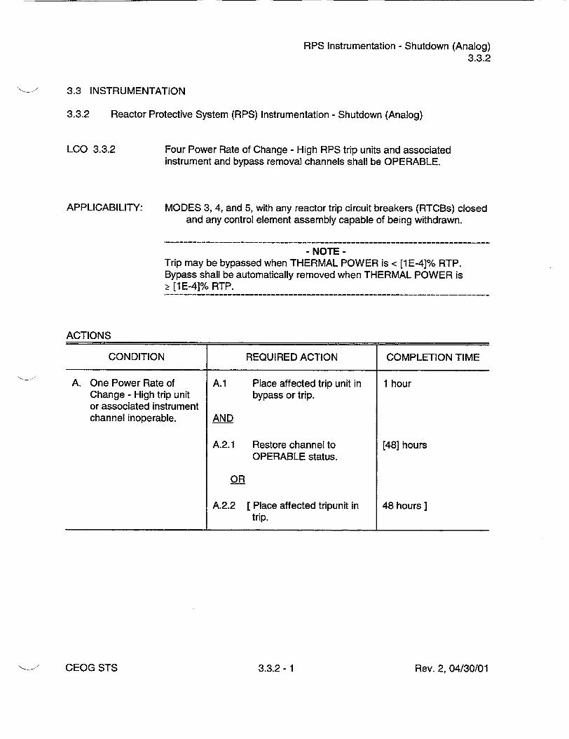
RPS Instrumentation - Shutdown (Analog) 3.3.2
3.3 INSTRUMENTATION
3.3.2 Reactor Protective System (RPS) Instrumentation - Shutdown (Analog)
LCO 3.3.2
APPLICABILITY:
Four Power Rate of Change - High RPS trip units and associated instrument and bypass removal channels shall be OPERABLE.
MODES 3, 4, and 5, with any reactor trip circuit breakers (RTCBs) closed and any control element assembly capable of being withdrawn.
- NOTE Trip may be bypassed when THERMAL POWER is < [1 E-4]% RTP. Bypass shall be automatically removed when THERMAL POWER is > [1 E-4]% RTP.
ACTIONS
CONDITION REQUIRED ACTION COMPLETION TIME
A. One Power Rate of A.1 Place affected trip unit in 1 hour Change - High trip unit bypass or trip. or associated instrument channel inoperable. AND
A.2.1 Restore channel to [48] hours
OPERABLE status.
OR
A.2.2 [ Place affected tripunit in 48 hours] trip.
Rev. 2, 04/30/01CEOG STS 3.3.2- 1

RPS Instrumentation - Shutdown (Analog) 3.3.2
ACTIONS (continued)
CONDITION REQUIRED ACTION COMPLETION TIME
B. Two Power Rate of ------------
Change - High trip units - NOTE or associated instrument LCO 3.0.4 is not channel inoperable, applicable.
B.1 Place one trip unit in 1 hour bypass and place the other trip unit in trip.
AND
B.2 [Restore one trip unitto 48 hours ] OPERABLE status.
C. One automatic bypass C.1 Disable bypass channel. 1 hour removal channel inoperable. OR
C.2.1 Place affected trip unit in 1 hour
bypass or trip.
AND
C.2.2.1 Restore bypass [48] hours removal channel and affected trip unit to OPERABLE status.
OR
C.2.2.2 [ Place affected tripunits in 48 hours] trip.
D. Two automatic bypass removal channels - NOTE inoperable. LCO 3.0.4 is not
applicable.
D.1 Disable bypass channels. 1 hour
OR
Rev. 2, 04/30/01CEOG STS 3.3.2- 2

RPS Instrumentation - Shutdown (Analog) 3.3.2
ACTIONS (continued)
CONDITION REQUIRED ACTION COMPLETION TIME
D.2.1 Place one affected trip unit 1 hour in bypass and place the other in trip.
AND
D.2.2 Restore one bypass [48] hours channel and the associated trip unit to OPERABLE status.
E. Required Action and E.1 Open all RTCBs. 6 hours associated Completion Time not met.
SURVEILLANCE REQUIREMENTS
SURVEILLANCE FREQUENCY
SR 3.3.2.1 Perform a CHANNEL CHECK of each wide range 12 hours power channel.
SR 3.3.2.2 Perform a CHANNEL FUNCTIONAL TEST on the 92 days Power Rate of Change trip function.
SR 3.3.2.3 Perform a CHANNEL FUNCTIONAL TEST on each 92 days automatic bypass removal function.
SR 3.3.2.4----------------------------------------- NOTE
Neutron detectors are excluded from CHANNEL CALIBRATION.
Perform a CHANNEL CALIBRATION, including [181 months bypass removal functions with Allowable Value _< [2.6] dpm.
Rev. 2, 04/30/01CEOG STS 3.3.2- 3
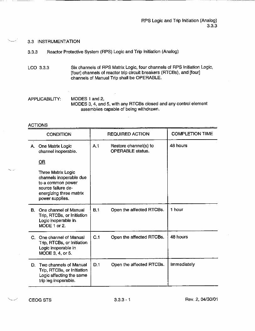
RPS Logic and Trip Initiation (Analog) 3.3.3
3.3 INSTRUMENTATION
3.3.3 Reactor Protective System (RPS) Logic and Trip Initiation (Analog)
LCO 3.3.3 Six channels of RPS Matrix Logic, four channels of RPS Initiation Logic, [four] channels of reactor trip circuit breakers (RTCBs), and [four] channels of Manual Trip shall be OPERABLE.
APPLICABILITY: MODES 1 and 2, MODES 3, 4, and 5, with any RTCBs closed and any control element
assemblies capable of being withdrawn.
ACTIONS
CONDITION REQUIRED ACTION COMPLETION TIME
A. One Matrix Logic A.1 Restore channel(s) to 48 hours
channel inoperable. OPERABLE status.
OR
Three Matrix Logic channels inoperable due to a common power source failure deenergizing three matrix power supplies.
B. One channel of Manual B.1 Open the affected RTCBs. 1 hour Trip, RTCBs, or Initiation Logic inoperable inMODE 1 or 2.
C. One channel of Manual C.1 Open the affected RTCBs. 48 hours Trip, RTCBs, or Initiation Logic inoperable in MODE 3, 4, or 5.
D. Two channels of Manual D.1 Open the affected RTCBs. Immediately Trip, RTCBs, or Initiation Logic affecting the same trip leg inoperable.
Rev. 2, 04/30/013.3.3- 1CEOG STS

RPS Logic and Trip Initiation (Analog) 3.3.3
ACTIONS (continued)
CONDITION REQUIRED ACTION COMPLETION TIME
E. Required Action and E.1 Be in MODE 3. 6 hours associated Completion Time of Condition A, B, AND or D not met.
E.2 Open all RTCBs. 6 hours OR
One or more Functions with two or more Manual Trip, Matrix Logic, Initiation Logic, or RTC13 channels inoperable for reasons other than Condition A or D.
SURVEILLANCE REQUIREMENTS
SURVEILLANCE FREQUENCY
SR 3.3.3.1 Perform a CHANNEL FUNCTIONAL TEST on each [31] days RTCB channel.
SR 3.3.3.2 Perform a CHANNEL FUNCTIONAL TEST on each [92] days RPS Logic: channel.
SR 3.3.3.3 Perform a CHANNEL FUNCTIONAL TEST on each Once within RPS Manual Trip channel. 7 days prior to
each reactor startup
SR 3.3.3.4 [Perform a CHANNEL FUNCTIONAL TEST, including [18] months] separate verification of the undervoltage and shunt trips, on each RTCB channel.
Rev. 2, 04/30/01 ICEOG STS 3.3.3- 2

ESFAS Instrumentation (Analog) 3.3.4
3.3 INSTRUMENTATION
3.3.4 Engineered Safety Features Actuation System (ESFAS) Instrumentation (Analog)
LCO 3.3.4
APPLICABILITY:
Four ESFAS trip units and associated instrument and bypass removal channels for each Function in Table 3.3.4-1 shall be OPERABLE.
MODES 1, 2, and 3.
ACTIONS
- NOTE Separate Condition entry is allowed for each ESFAS Function.
CONDITION REQUIRED ACTION COMPLETION TIME
A. [One Containment Spray A.1 Place affected trip 1 hour] Actuation Signal (CSAS) unit in bypass. trip unit or associated instrument inoperable.
B. One or more Functions B.1 Place affected trip unit in 1 hour with one ESFAS trip unit bypass or trip. or associated instrument channel (except CSAS) AND inoperable.
B.2.1 Restore channel to [48] hours OPERABLE status.
OR
B.2.2 [Place affected trip unit in 48 hours] trip.
Rev. 2, 04/30/01CEOG STS 3.3.4- 1

ESFAS Instrumentation (Analog) 3.3.4
ACTIONS (continued)
CONDITION REQUIRED ACTION COMPLETION TIME
C. One or more Functions ---------------------------with two ESFAS trip - NOTE units or associated LCO 3.0.4 is not instrument channels applicable. (except CSAS) inoperable. C.1 Place one trip unit in 1 hour
bypass and place the other trip unit in trip.
AND
C.2 Restore one trip unit to [48] hours OPERABLE status.
D. One or more Functions D.1 Disable bypass channel. 1 hour with one automatic bypass removal channel OR inoperable.
D.2.1 Place affected trip units in 1 hour bypass or trip.
AND
D.2.2.1 Restore bypass removal [48] hours channel and affected trip units to OPERABLE status.
OR
D.2.2.2 [ Place affected trip units in 48 hours] trip.
E. One or more Functions with two automatic - NOTE bypass removal LCO 3.0.4 is not channels inoperable, applicable.
E.1 Disable bypass channels. 1 hour
OR
Rev. 2, 04/30/01CEOG STS 3.3.4- 2
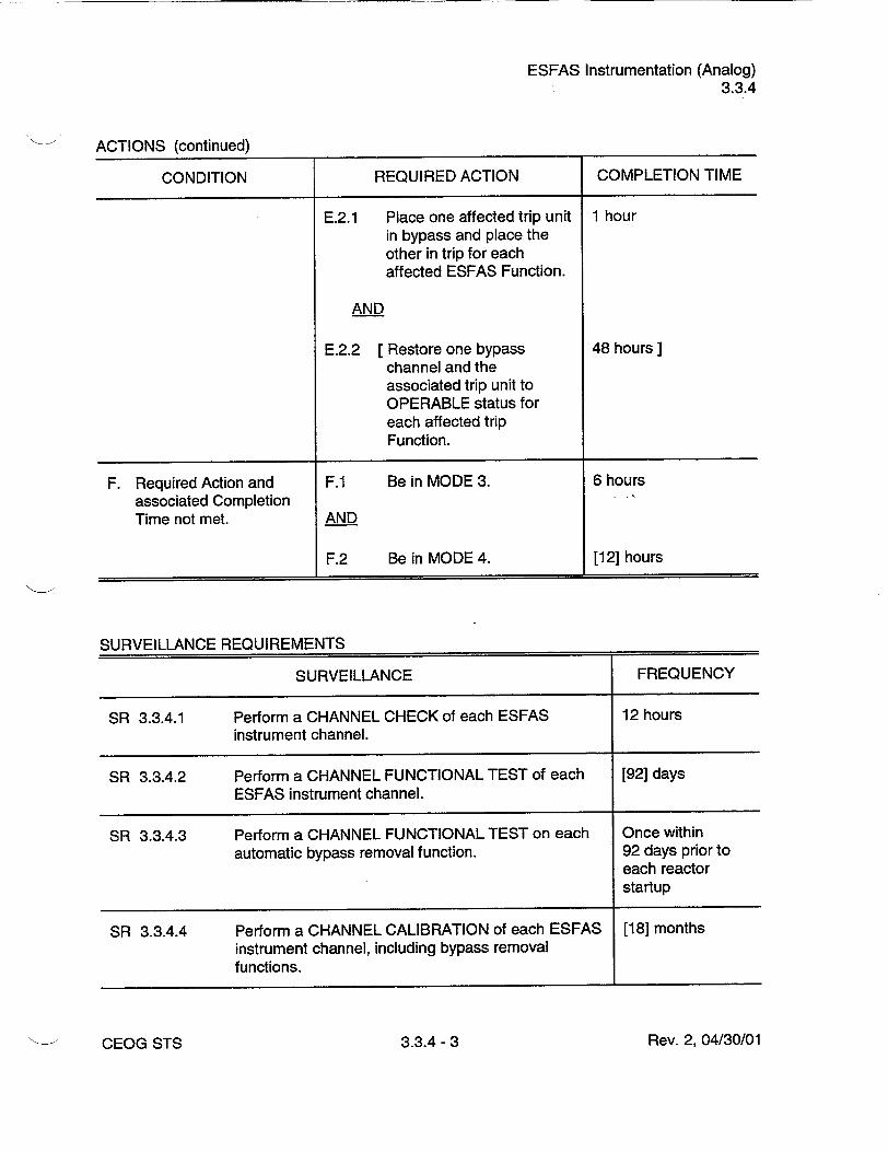
ESFAS Instrumentation (Analog) 3.3.4
ACTIONS (continued)
CONDITION REQUIRED ACTION COMPLETION TIME
E.2.1 Place one affected trip unit 1 hour in bypass and place the other in trip for each affected ESFAS Function.
AND
E.2.2 [Restore one bypass 48 hours] channel and the associated trip unit to OPERABLE status for each affected trip Function.
F. Required Action and F.1 Be in MODE 3. 6 hours associated Completion Time not met. AND
F.2 Be in MODE 4. [12] hours
SURVEILLANCE REQUIREMENTS
SURVEILLANCE FREQUENCY
SR 3.3.4.1 Perform a CHANNEL CHECK of each ESFAS 12 hours instrument channel.
SR 3.3.4.2 Perform a CHANNEL FUNCTIONAL TEST of each [92] days ESFAS instrument channel.
SR 3.3.4.3 Perform a CHANNEL FUNCTIONAL TEST on each Once within automatic bypass removal function. 92 days prior to
each reactor startup
SR 3.3.4.4 Perform a CHANNEL CALIBRATION of each ESFAS [18] months instrument channel, including bypass removal functions.
Rev. 2, 04/30/01CEOG STS 3.3.4- 3

ESFAS Instrumentation (Analog) 3.3.4
SURVEILLANCE REQUIREMENTS (continued)
SURVEILLANCE FREQUENCY
SR 3.3.4.5 Verify ESF RESPONSE TIME is within limits. [18] months on a STAGGERED TEST BASIS
Rev. 2, 04/30/01CEOG STS 3.3.4- 4

ESFAS Instrumentation (Analog) 3.3.4
Table 3.3.4-1 (page 1 of 2) Engineered Safety Features Actuation System Instrumentation
SURVEILLANCE ALLOWABLE FUNCTION MODES REQUIREMENTS VALUE
1. Safety Injection Actuation Signal (SIAS)
a. Containment Pressure - High 1,2,3 SR 3.3.4.1 • [19.0] psia SR 3.3.4.2 SR 3.3.4.4 SR 3.3.4.5
b. Pressurizer Pressure - Low(a) 1,2,3 SR 3.3.4.1 Ž [1687] psia SR 3.3.4.2 SR 3.3.4.3 SR 3.3.4.4 SR 3.3.4.5
2. Containment Spray Actuation Signal(b)
a. Containment Pressure - High 1,2,3 SR 3.3.4.1 • [19.0] psia SR 3.3.4.2 SR 3.3.4.4 SR 3.3.4.5
3. Containment Isolation Actuation Signal
a. Containment Pressure - High 1,2,3 SR 3.3.4.1 < [19.0] psia SR 3.3.4.2 SR 3.3.4.4 SR 3.3.4.5
[b. Containment Radiation - High 1,2,3 SR 3.3.4.1 • [2x SR 3.3.4.2 Background]] SR 3.3.4.4 SR 3.3.4.5
(a) Pressurizer Pressure - Low may be manually bypassed when pressurizer pressure is < [1800] psia. The
bypass shall be automatically removed whenever pressurizer pressure is Ž [1800] psia.
E (b) SIAS is also required as a permissive to initiate containment spray. ]
Rev. 2, 04/30/01CEOG STS 3.3.4- 5
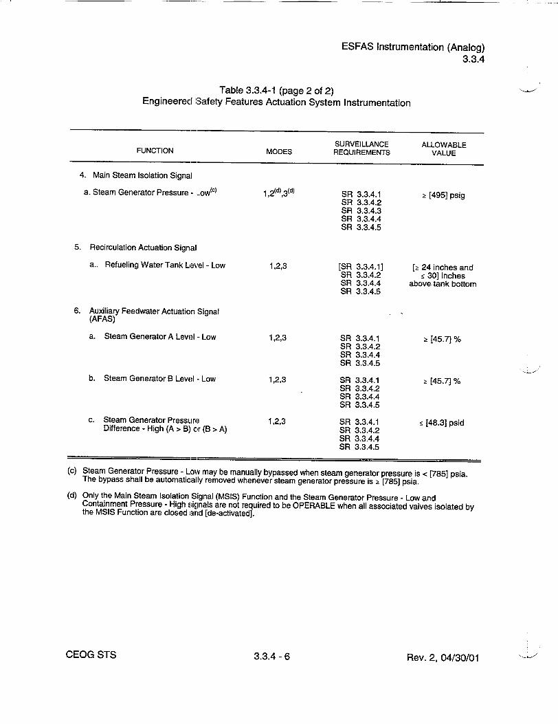
ESFAS Instrumentation (Analog) 3.3.4
Table 3.3.4-1 (page 2 of 2) Engineered Safety Features Actuation System Instrumentation
SURVEILLANCE ALLOWABLE FUNCTION MODES REQUIREMENTS VALUE
4. Main Steam Isolation Signal
a. Steam Generator Pressure - Low(c) 1 ,2 (d),3 (d) SR 3.3.4.1 Ž [495] psig SR 3.3.4.2 SR 3.3.4.3 SR 3.3.4.4 SR 3.3.4.5
5. Recirculation Actuation Signal
a.. Refueling Water Tank Level- Low 1,2,3 [SR 3.3.4.1] [t 24 inches and SR 3.3.4.2 g 30] inches SR 3.3.4.4 above tank bottom SR 3.3.4.5
6. Auxiliary Feedwater Actuation Signal (AFAS)
a. Steam Generator A Level - Low 1,2,3 SR 3.3.4.1 > [45.7] % SR 3.3.4.2 SR 3.3.4.4 SR 3.3.4.5
b. Steam Generator B Level - Low 1,2,3 SR 3.3.4.1 [ [45.7] % SR 3.3.4.2 SR 3.3.4.4 SR 3.3.4.5
c. Steam Generator Pressure 1,2,3 SR 3.3.4.1 • [48.3] psid Difference - High (A > B) or (B > A) SR 3.3.4.2
SR 3.3.4.4 SR 3.3.4.5
(c) Steam Generator Pressure - Low may be manually bypassed when steam generator pressure is < [785] psia. The bypass shall be automatically removed whenever steam generator pressure is • [785] psia.
(d) Only the Main Steam Isolation Signal (MSIS) Function and the Steam Generator Pressure - Low and Containment Pressure - High signals are not required to be OPERABLE when all associated valves isolated by the MSIS Function are closed and [de-activated].
Rev. 2, 04/30/01CEOG STS 3.3.4- 6

ESFAS Logic and Manual Trip (Analog) 3.3.5
3.3 INSTRUMENTATION
3.3.5 Engineered Safety Features Actuation System (ESFAS) Logic and Manual Trip (Analog)
LCO 3.3.5
APPLICABILITY:
Two ESFAS Manual Trip and two ESFAS Actuation Logic channels shall be OPERABLE for each ESFAS Function specified in Table 3.3.5-1.
According to Table 3.3.5-1.
ACTIONS
- NOTE Separate Condition entry is allowed for each Function.
CONDITION REQUIRED ACTION COMPLETION TIME
A. One or more Functions A.1 Restore channel to 48 hours with one Auxiliary OPERABLE status. Feedwater Actuation Signal (AFAS) Manual Trip or Actuation Logic channel inoperable.
B. Two AFAS Manual Trip B.1 Be in MODE 3. 6 hours or Actuation Logic channels inoperable. AND
OR B.2 Be in MODE 4. [12] hours
Required Action and associated Completion Time of Condition A not met.
C. One or more Functions C.1 Restore channel to 48 hours with one Manual Trip or OPERABLE status. Actuation Logic channel inoperable except AFAS.
Rev. 2, 04/30/01CEOG STS 3.3.5- 1
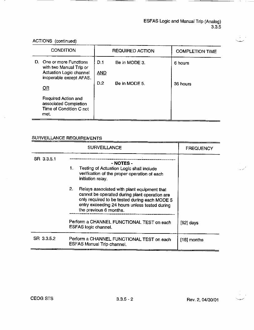
ESFAS Logic and Manual Trip (Analog) 3.3.5
ACTIONS (continued)
CONDITION REQUIRED ACTION COMPLETION TIME
D. One or more Functions D.1 Be in MODE 3. 6 hours with two Manual Trip or Actuation Logic channel AND inoperable except AFAS.
D.2 Be in MODE 5. 36 hours OR
Required Action and associated Completion Time of Condition C not met.
SURVEILLANCE REQUIREMENTS
SURVEILLANCE FREQUENCY
SR 3.3.5.1---------------------NOTES
1. Testing of Actuation Logic shall include verification of the proper operation of each initiation relay.
2. Relays associated with plant equipment that cannot be operated during plant operation are only required to be tested during each MODE 5 entry exceeding 24 hours unless tested during the previous 6 months.
Perform a CHANNEL FUNCTIONAL TEST on each [92] days ESFAS logic channel.
SR 3.3.5.2 Perform a CHANNEL FUNCTIONAL TEST on each [18] months ESFAS Manual Trip channel.
Rev. 2, 04/30/01CEOG STS 3.3.5- 2
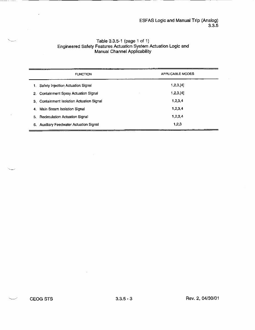
ESFAS Logic and Manual Trip (Analog) 3.3.5
Table 3.3.5-1 (page 1 of 1) Engineered Safety Features Actuation System Actuation Logic and
Manual Channel Applicability
FUNCTION APPLICABLE MODES
1. Safety Injection Actuation Signal 1,2,3,[4]
2. Containment Spray Actuation Signal 1,2,3,[4]
3.. Containment Isolation Actuation Signal 1,2,3,4
4. Main Steam Isolation Signal 1,2,3,4
5. Recirculation Actuation Signal 1,2,3,4
6. Auxiliary Feedwater Actuation Signal 1,2,3
Rev. 2, 04/30/01CEOG STS 3.3.5- 3

DG - LOVS (Analog) 3.3.6
3.3 INSTRUMENTATION
3.3.6 Diesel Generator (DG) - Loss of Voltage Start (LOVS) (Analog)
LCO 3.3.6
APPLICABILITY:
[Four] channels of Loss of Voltage Function and [four] channels of Degraded Voltage Function auto-initiation instrumentation per DG shall be OPERABLE.
MODES 1, 2, 3, and 4, When associated DG is required to be OPERABLE by LCO 3.8.2, "AC
Sources - Shutdown."
ACTIONS
- NOTE Separate Condition entry is allowed for each Function.
CONDITION REQUIRED ACTION COMPLETION TIME
A. One or more Functions A.1 Place channel in bypass or 1 hour with one channel per DG trip. inoperable.
AND
A.2.1 Restore channel to [48] hours
OPERABLE status.
OR
A.2.2 [ Place the channel intrip. 48 hours ]
B. One or more Functions B.1 Enter applicable 1 hour with two channels per Conditions and Required DG inoperable. Actions for the associated
DG made inoperable by DG - LOVS instrumentation.
OR
Rev. 2, 04/30/013.3.6- 1CEOG STS
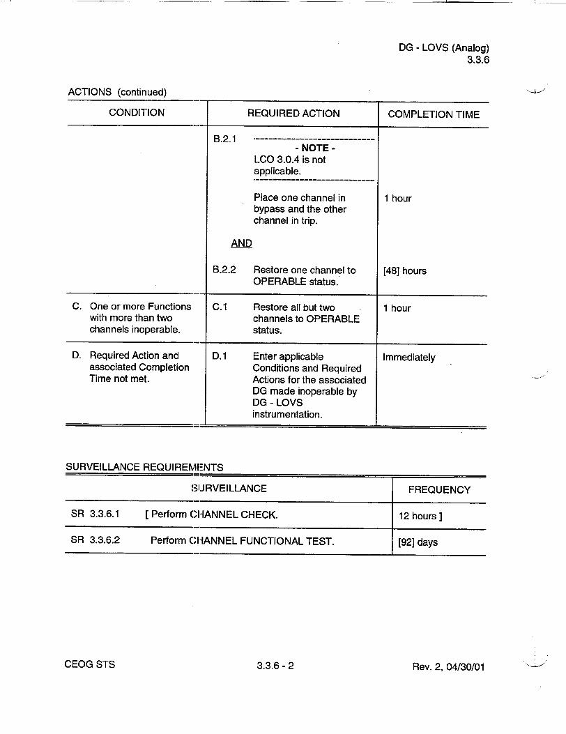
DG - LOVS (Analog) 3.3.6
ACTIONS (continued)
CONDITION REQUIRED ACTION COMPLETION TIME
B.2.1 - NOTE
LCO 3.0.4 is not applicable.
Place one channel in 1 hour bypass and the other channel in trip.
AND
B.2.2 Restore one channel to [48] hours OPERABLE status.
C. One or more Functions C.1 Restore all but two 1 hour with more than two channels to OPERABLE channels inoperable, status.
D. Required Action and D. 1 Enter applicable Immediately associated Completion Conditions and Required Time not met. Actions for the associated
DG made inoperable by DG - LOVS instrumentation.
SURVEILLANCE REQUIREMENTS
SUJRVEILLANCE FREQUENCY
SR 3.3.6.1 [Perform CHANNEL CHECK. 12 hours ]
SR 3.3.6.2 Perform CHANNEL FUNCTIONAL TEST. [92] days
Rev. 2, 04/30/01CEOG STS 3.3.6-2

DG - LOVS (Analog) 3.3.6
SURVEILLANCE REQUIREMENTS (continued)
SURVEILLANCE
Perform CHANNEL CALIBRATION with setpoint Allowable Values as follows:
a. Degraded Voltage Function > [3180] V and _< [3220] V
Time delay: Ž [ ] seconds and • [ ] seconds at [ ] V and
b. Loss of Voltage Function Ž [3180] V and < [3220] V
Time delay: > [ ] seconds and _ [ ] seconds at [IV.
FREQUENCY
[18] months
Rev. 2, 04/30/01
SR 3.3.6.3
CEOG STS 3.3.6- 3

CPIS (Analog) 3.3.7
3.3 INSTRUMENTATION
3.3.7 Containment Purge Isolation Signal (CPIS) (Analog)
LCO 3.3.7
APPLICABILITY:
[Four] CPIS containment radiation monitor channels and one CPIS automatic Actuation Logic and one Manual Trip train shall be OPERABLE.
During movement of [recently] irradiated fuel assemblies within containment.
ACTIONS
CONDITION REQUIRED ACTION COMPLETION TIME
A. One radiation monitor A.1 Place the affected channel 4 hours
channel inoperable, in trip.
OR
A.2 Suspend movement of Immediately [recently] irradiated fuel assemblies within containment.
B. One required Manual B.1 Place and maintain Immediately Trip or automatic containment purge and Actuation Logic train exhaust valves in closed inoperable, position.
OR OR
More than one radiation B.2 Enter applicable Immediately monitor channel Conditions and Required inoperable. Actions for affected valves
of LCO 3.9.3, OR "Containment
Penetrations," made Required Action and inoperable by isolation associated Completion instrumentation. Time of Condition A not met.
Rev. 2, 04/30/01CEOG STS 3.3.7- 1

CPIS (Analog) 3.3.7
SURVEILLANCE REQUIREMENTS
SURVEILLANCE FREQUENCY
SR 3.3.7.1 Perform a CHANNEL CHECK on each containment 12 hours radiation monitor channel.
SR 3.3.7.2 Perform a CHANNEL FUNCTIONAL TEST on each [92] days containment radiation monitor channel.
Verify CPIS high radiation setpoint is less than or equal to the Allowable Value of [220 mR/hr].
S R 3 .3 .7.3 ------------------------------------------------------ NOTE
Testing of Actuation Logic shall include verification of the proper operation of each initiation relay.
Perform a CHANNEL FUNCTIONAL TEST on each [31] days CPIS Actuation Logic channel.
SR 3.3.7.4 Perform a. CHANNEL CALIBRATION on each [18] months containment radiation monitor channel.
SR 3.3.7.5 Perform a CHANNEL FUNCTIONAL TEST on each [18] months CPIS Manual Trip channel.
SR 3.3.7.6 Verify CPI!S response time of each containment [18] months on a radiation channel is within limits. STAGGERED
TEST BASIS
CEOG STS Rev. 2, 04/30/013.3.7- 2

DG - LOVS (Digital) 3.3.7
SURVEILLANCE REQUIREMENTS (continued)
SURVEILLANCE
Perform CHANNEL CALIBRATION with setpoint Allowable Values as follows:
a. Degraded Voltage Function • [3180] V and < [3220] V
Time delay: > [ ] seconds and < [ ] seconds at [ ] V and
b. Loss of Voltage Function > [3180] V and _< [3220] V
Time delay: > [ ] seconds and _ [ seconds at []V.
FREQUENCY
[18] months
Rev. 2, 04/30/01
SR 3.3.7.3
CEOG STS 3.3.7- 3
I
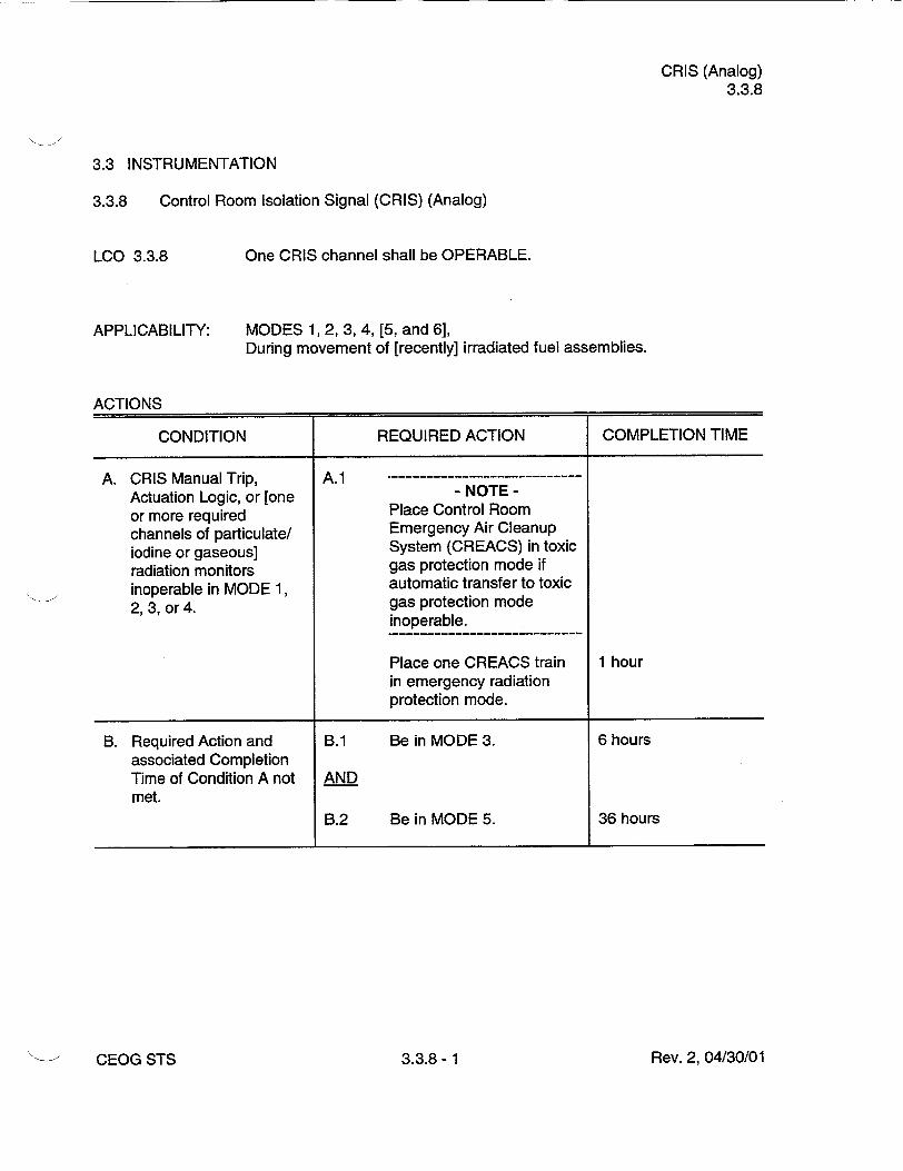
CRIS (Analog) 3.3.8
3.3 INSTRUMENTATION
3.3.8 Control Room Isolation Signal (CRIS) (Analog)
LCO 3.3.8 One CRIS channel shall be OPERABLE.
APPLICABILITY: MODES 1, 2, 3, 4, [5, and 6], During movement of [recently] irradiated fuel assemblies.
ACTIONS
CONDITION REQUIRED ACTION COMPLETION TIME
A. CRIS Manual Trip, A.1
Actuation Logic, or [one - NOTE or more required Place Control Room
channels of particulate/ Emergency Air Cleanup
iodine or gaseous] System (CREACS) in toxic
radiation monitors gas protection mode if
inoperable in MODE 1, automatic transfer to toxic
2, 3, or 4. gas protection mode inoperable.
Place one CREACS train 1 hour in emergency radiation protection mode.
B. Required Action and B.1 Be in MODE 3. 6 hours associated Completion Time of Condition A not AND met.
B.2 Be in MODE 5. 36 hours
Rev. 2, 04/30/01CEOG STS 3.3.8- 1

CRIS (Analog) 3.3.8
ACTIONS (continued)
CONDITION REQUIRED ACTION COMPLETION TIME
C. CRIS Manual Trip, C.1 Actuation Logic, or [one - NOTE or more required Place CREACS in toxic channels of particulate/ gas protection mode if iodine or gaseous] automatic transfer to toxic radiation monitors gas protection mode inoperable [in MODE 5 inoperable. or 6], during movement of [recently] irradiated Place one CREACS train Immediately fuel assemblies, in emergency radiation
protection mode.
OR
C.2.1 Suspend movement of Immediately [recently] irradiated fuel assemblies.
AND
- NOTE Limited plant cooldown or boron dilution is allowed provided the change is accounted for in the calculated SDM.
C.2.2 Suspend positive reactivity Immediately additions.
SURVEILLANCE REQUIREMENTS
SURVEILLANCE FREQUENCY
SR 3.3.8.1 Perform a CHANNEL CHECK on the required control 12 hours room radiation monitor channel.
CEOG STS 3.3.8- 2 Rev. 2, 04/30/01

CRIS (Analog) 3.3.8
SURVEILLANCE REQUIREMENTS (continued)
SURVEILLANCE FREQUENCY
SR 3.3.8.2 Perform a CHANNEL FUNCTIONAL TEST on the [92] days required CRIS radiation monitor channel.
Verify CRIS high radiation setpoint is less than or equal to the Allowable Value of [6E4] cpm above normal background.
SR 3.3.8.3 - NOTES
1. Surveillance of Actuation Logic shall include verification of the proper operation of each initiation relay.
2. Relays associated with plant equipment that cannot be operated during plant operation are only required to be tested during each MODE 5 entry exceeding 24 hours unless tested within the previous 6 months.
Perform a CHANNEL FUNCTIONAL TEST on the [31] days required CRIS Actuation Logic channel.
SR 3.3.8.4 Perform a CHANNEL CALIBRATION on the required [18] months CRIS radiation monitor channel.
SR 3.3.8.5 Perform a CHANNEL FUNCTIONAL TEST on the [18] months required CRIS Manual Trip channel.
SR 3.3.8.6 [Verify response time of required CRIS channel is [18] months] within limits.
Rev. 2, 04/30/01CEOG STS 3.3.8- 3

CVCS Isolation Signal (Analog) 3.3.9
3.3 INSTRUMENTATION
3.3.9 Chemical and Volume Control System (CVCS) Isolation Signal (Analog)
LCO 3.3.9
APPLICABILITY:
Four channels of West Penetration Room/Letdown Heat Exchanger Room pressure sensing and two Actuation Logic channels shall be OPERABLE.
MODES 1, 2, 3, and 4.
ACTIONS
CONDITION REQUIRED ACTION COMPLETION TIME
A. One Actuation Logic A.1 Restore the channel to 48 hours channel inoperable. OPERABLE status.
B. One CVCS isolation B.1 Place the channel in 1 hour instrument channel bypass or trip. inoperable.
AND
B.2.1 Restore the channel to 48 hours
OPERABLE status.
OR
B.2.2 Place the channel in trip. 48 hours
C. Two CVCS isolation - ----------
instrument channels - NOTE inoperable. LCO 3.0.4 is not
applicable.
C.1 Place one channel in 1 hour bypass and place the other channel in trip.
AND
C.2 Restore one channel to 48 hours OPERABLE status.
Rev. 2, 04/30/01CEOG STS 3.3.9- 1

CVCS Isolation Signal (Analog) 3.3.9
ACTIONS (continued)
CONDITION REQUIRED ACTION COMPLETION TIME
D. Two Actuation Logic D.1 Be in MODE 3. 6 hours channels inoperable.
AND OR
Required Action and D.2 Be in MODE 5. 36 hours associated Completion Time not met.
SURVEILLANCE REQUIREMENTS
SURVEILLANCE FREQUENCY
SR 3.3.9.1 Perform a CHANNEL CHECK. 12 hours
SR 3.3.9.2- ----------------NOTES
1. Testing of Actuation Logic shall include the verification of the proper operation of each initialion relay.
2. Relays associated with plant equipment that cannot be operated during plant operation are only required to be tested during each MODE 5 entry exceeding 24 hours unless tested within the previous 6 months.
Perform a CHANNEL FUNCTIONAL TEST on each 31 days CVCS isolation channel with setpoints in accordance with the following Allowable Values:
West Penetration Room Pressure - High < .5 psig
Letdown Fleat Exchanger Room Pressure - High <_.5 psig
SR 3.3.9.3 Perform a CHANNEL CALIBRATION on each CVCS 18 months isolation pressure indicating channel.
CEOG STS 3.3.9- 2 Rev. 2, 04/30/01
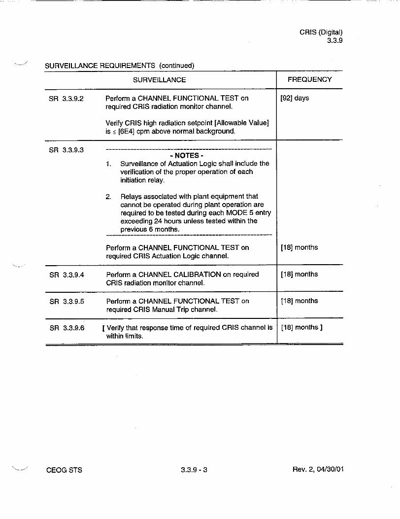
CRIS (Digital) 3.3.9
SURVEILLANCE REQUIREMENTS (continued)
SURVEILLANCE FREQUENCY
SR 3.3.9.2 Perform a CHANNEL FUNCTIONAL TEST on [92] days required CRIS radiation monitor channel.
Verify CRIS high radiation setpoint [Allowable Value] is _ [6E4] cpm above normal background.
SR 3.3.9.3 -NOTES
1. Surveillance of Actuation Logic shall include the verification of the proper operation of each initiation relay.
2. Relays associated with plant equipment that cannot be operated during plant operation are required to be tested during each MODE 5 entry exceeding 24 hours unless tested within the previous 6 months.
Perform a CHANNEL FUNCTIONAL TEST on [18] months required CRIS Actuation Logic channel.
SR 3.3.9.4 Perform a CHANNEL CALIBRATION on required [18] months CRIS radiation monitor channel.
SR 3.3.9.5 Perform a CHANNEL FUNCTIONAL TEST on [18] months required CRIS Manual Trip channel.
SR 3.3.9.6 [Verify that response time of required CRIS channel is [18] months] within limits.
Rev. 2, 04/30/01CEOG STS 3.3.9- 3

SBFAS (Analog) 3.3.10
3.3 INSTRUMENTATION
3.3.10 Shield Building Filtration Actuation Signal (SBFAS) (Analog)
LCO 3.3.10
APPLICABILITY:
Two channels of SBFAS automatic and two channels of Manual Trip shall be OPERABLE.
MODES 1, 2, 3, and 4.
ACTIONS
CONDITION REQUIRED ACTION COMPLETION TIME
A. One Manual Trip or A.1 Restore the channel to 48 hours Actuation Logic channel OPERABLE status. inoperable.
B. Required Action and B.1 Be in MODE 3. 6 hours associated Completion Time not met. AND
B.2 Be in MODE 5. 36 hours
SURVEILLANCE REQUIREMENTS
SURVEILLANCE FREQUENCY
SR 3.3.10.1 Perform a CHANNEL FUNCTIONAL TEST on each [92] days SBFAS automatic actuation channel.
SR 3.3.10.2 Perform a CHANNEL FUNCTIONAL TEST on each [18] months SBFAS Manual Trip channel.
Rev. 2, 04/30/01CEOG STS 3.3.10- 1

PAM Instrumentation (Analog) 3.3.11
3.3 INSTRUMENTATION
3.3.11 Post Accident Monitoring (PAM) Instrumentation (Analog)
The PAM instrumentation for each Function in Table 3.3.11 -1 shall be OPERABLE.
MODES 1, 2, and 3.
ACTIONS
- NOTES 1. LCO 3.0.4 is not applicable.
2. Separate Condition entry is allowed for each Function.
CONDITION REQUIRED ACTION COMPLETION TIME
A. One or more Functions A.1 Restore required channel 30 days with one required to OPERABLE status. channel inoperable.
B. Required Action and B.1 Initiate action in Immediately associated Completion accordance with Time of Condition A not Specification 5.6.7. met.
C. 1--------------------C Restore one channel to 7 days - NOTE - OPERABLE status.
Not applicable to hydrogen monitor channels.
One or more Functions with two required channels inoperable.
D. Two hydrogen monitor D.1 Restore one hydrogen 72 hours channels inoperable, monitor channel to
OPERABLE status.
Rev. 2, 04/30/01
LCO 3.3.11
APPLICABILITY:
CEOG STS 3.3.11- 1

PAM Instrumentation (Analog) 3.3.11
ACTIONS (continued)
CONDITION REQUIRED ACTION COMPLETION TIME
E. Required Action and E.1 Enter the Condition Immediately associated Completion referenced in Time of Condition C or D) Table 3.3.11-1 for the not met. channel.
F. As required by Required F.1 Be in MODE 3. 6 hours Action E.1 and referenced in AND Table 3.3.11-1.
F.2 Be in MODE 4. 12 hours
G. [As required by Required G. 1 Initiate action in Immediately] Action E.1 and accordance with referenced in Specification 5.6.7. Table 3.3.11-1.
SURVEILLANCE REQUIREMENTS
- NOTE These SRs apply to each PAM instrumentation Function in Table 3.3.11-1.
SURVEILLANCE FREQUENCY
SR 3.3.11.1 Perform CHANNEL CHECK for each required 31 days instrumentation channel that is normally energized.
SR 3.3.11.2 - NOTE
Neutron detectors are excluded from CHANNEL CALIBRA'TION.
Perform CHANNEL CALIBRATION. [18] months
Rev. 2, 04/30/01CEOG STS 3.3.11 -2

PAM Instrumentation (Analog) 3.3.11
Table 3.3.11-1 (page 1 of 1) Post Accident Monitoring Instrumentation
CONDITIONS REFERENCED FROM
REQUIRED FUNCTION REQUIRED CHANNELS ACTION E.1
1. [Logarithmic] Neutron Flux 2 F
2. Reactor Coolant System Hot Leg Temperature 2 per loop F
3. Reactor Coolant System Cold Leg Temperature 2 per loop F
4. Reactor Coolant System Pressure (wide range) 2 F
5. Reactor Vessel Water Level 2 [G]
6. Containment Sump Water Level (wide range) 2 F
7. Containment Pressure (wide range) 2 F
8. Penetration Flow Path Containment Isolation 2 per penetr on flow F Valve Position path a-0
9. Containment Area Radiation (high range) 2 [G]
10. Containment Hydrogen Monitors 2 F
11. Pressurizer Level 2 F
12. Steam Generator Water Level (wide range) 2 per steam generator F
13. Condensate Storage Tank Level 2 F
14. Core Exit Temperature - Quadrant [1] 2(c) F
15. Core Exit Temperature - Quadrant [2] 2 (c) F
16. Core Exit Temperature - Quadrant [3] 2 (c) F
17. Core Exit Temperature - Quadrant [4] 2(c) F
18. Auxiliary Feedwater Flow 2 F
(a) Not required for isolation valves whose associated penetration is isolated by at least one closed and deactivated automatic valve, closed manual valve, blind flange, or check valve with flow through the valve secured.
(b) Only one position indication channel is required for penetration flow paths with only one installed control room indication channel.
(c) A channel consists of two or more core exit thermocouples.
- REVIEWER'S NOTE Table 3.3.11-1 shall be amended for each unit as necessary to list: 1. All Regulatory Guide 1.97, Type A instruments and 2. All Regulatory Guide 1.97, Category I, non-Type A instruments specified in the unit's Regulatory Guide 1.97,
Safety Evaluation Report.
Rev. 2, 04/30/013.3.11- 3CEOG STS

Remote Shutdown System (Analog) 3.3.12
3.3 INSTRUMENTATION
3.3.12 Remote Shutdown System (Analog)
LCO 3.3.12
APPLICABILITY:
The Remote Shutdown System Functions shall be OPERABLE.
MODES 1, 2, and 3.
- NOTES 1. LCO 3.0.4 is not applicable.
2. Separate Condition entry is allowed for each Function.
ACTIONS
CONDITION REQUIRED ACTION COMPLETION TIME
A. One or more required A.1 Restore required 30 days Functions inoperable. Functions to OPERABLE
status.
B. Required Action and B.1 Be in MODE 3. 6 hours associated Completion Time not met. AND
B.2 Be in MODE 4. [12] hours
SURVEILLANCE REQUIREMENTS
SURVEILLANCE FREQUENCY
SR 3.3.12.1 [Perform CHANNEL CHECK for each required 31 days] instrumentation channel that is normally energized.
SR 3.3.12.2 Verify each required control circuit and transfer [18] months switch is capable of performing the intended function.
Rev. 2, 04/30/01CEOG STS 3.3.12- 1

Remote Shutdown System (Analog) 3.3.12
SURVEILLANCE REQUIREMENTS (continued)
SURVEILLANCE FREQUENCY
SR 3.3.12.3- --------------------------- NOTE
Neutron detectors are excluded from the CHANNEL CALIBRATION.
Perform CHANNEL CALIBRATION for each required [18] months instrumentation channel.
SR 3.3.12.4 [Perform CHANNEL FUNCTIONAL TEST of the 18 months J reactor trip circuit breaker open/closed indication.
Rev. 2, 04/30/01CEOG STS 3.3.12 -2

[Logarithmic] Power Monitoring Channels (Analog) 3.3.13
3.3 INSTRUMENTATION
3.3.13 [Logarithmic] Power Monitoring Channels (Analog)
LCO 3.3.13
APPLICABILITY:
Two channels of [logarithmic] power level monitoring instrumentation shall be OPERABLE.
MODES 3, 4, and 5, with the reactor trip circuit breakers open or Control Element Assembly (CEA) Drive System not capable of CEA withdrawal.
ACTIONS
CONDITION REQUIRED ACTION COMPLETION TIME
A. One or more required channel(s) inoperable. - NOTE
Limited plant cooldown or boron dilution is allowed provided the change is accounted for in the calculated SDM.
A.1 Suspend all operations Immediately involving positive reactivity additions.
AND
A.2 Perform SDM verification 4 hours in accordance with SR 3.1.1.1, if Tavg > AND 200 OF.
Once per 12 hours thereafter
Rev. 2, 04/30/01CEOG STS 3.3.13- 1
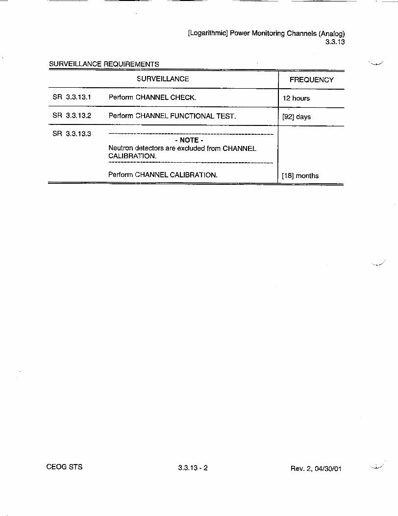
[Logarithmic] Power Monitoring Channels (Analog) 3.3.13
SURVEILLANCE REQUIREMENTS
SURVEILLANCE FREQUENCY
SR 3.3.13.1 Perform CHANNEL CHECK. 12 hours
SR 3.3.13.2 Perform CHANNEL FUNCTIONAL TEST. [92] days
S R 3 .3 .13 .3 ------------------------------------------------------- NOTE
Neutron detectors are excluded from CHANNEL CALIBRATION.
Perform CHANNEL CALIBRATION. [18] months
Rev. 2, 04/30/01CEOG STS 3.3.13 -2

SDM (Digital) 3.1.1
3.1 REACTIVITY CONTROL SYSTEMS
3.1.1 SHUTDOWN MARGIN (SDM) (Digital)
LCO 3.1.1 SHUTDOWN MARGIN (SDM) shall be within the limits provided in the COLR.
APPLICABILITY: MODES 3, 4, and 5.
ACTIONS
CONDITION REQUIRED ACTION COMPLETION TIME
A. SDM not within limit. A.1 Initiate boration to restore 15 minutes SDM to within limit.
SURVEILLANCE REQUIREMENTS
Rev. 2, 04/30/01CEOG STS 3.1.1- 1

Reactivity Balance (Digital) 3.1.2
3.1 REACTIVITY CONTROL SYSTEMS
3.1.2 Reactivity Balance (Digital)
LCO 3.1.2
APPLICABILITY:
The core reactivity balance shall be within ± 1 % Ak/k of predicted values.
MODES 1 and 2.
ACTIONS
CONDITION REQUIRED ACTION COMPLETION TIME
A. Core reactivity balance A.1 Re-evaluate core design 7 days not within limit, and safety analysis and
determine that the reactor core is acceptable for continued operation.
AND
A.2 Establish appropriate 7 days operating restrictions and SRs.
B. Required Action and B.1 Be in MODE 3. 6 hours associated Completion Time not met.
Rev. 2, 04/30/01CEOG STS 3.1.2- 1

Reactivity Balance (Digital) 3.1.2
SURVEILLANCE REQUIREMENTS
SURVEILLANCE FREQUENCY
SR 3.1.2.1 - NOTES
1. The predicted reactivity values may be adjusted (normalized) to correspond to the measured core reactivity prior to exceeding a fuel burnup of 60 effective full power days (EFPD) after each fuel loading.
2. This Surveillance is not required to be performed prior to entry into MODE 2.
Verify overall core reactivity balance is within Prior to entering + 1.0% Ak/k of predicted values. MODE 1 after fuel
loading
AND
- NOTE Only required after 60 EFPD
31 EFPD________________________________________________________________________________ L ___________________________________________________________
Rev. 2, 04/30/01CEOG STS 3.1.2- 2

MTC (Digital) 3.1.3
3.1 REACTIVITY CONTROL SYSTEMS
3.1.3 Moderator Temperature Coefficient (MTC) (Digital)
The Moderator Temperature Coefficient (MTC) shall be maintained within the limits specified in the COLR, and a maximum positive limit as specified below:
a. [0.5 E-4 Ak/kI°F] when THERMAL POWER is _ 70% RTP and
b. [0.0 Ak/k/°F] when THERMAL POWER is > 70% RTP.
APPLICABILITY: MODES 1 and 2.
ACTIONS
CONDITION REQUIRED ACTION COMPLETION TIME
A. MTC not within limits. A.1 Be in MODE 3. 6 hours
SURVEILLANCE REQUIREMENTS
SURVEILLANCE FREQUENCY
SR 3.1.3.1 Verify MTC is within the upper limit. Prior to entering MODE 1 after each fuel loading
Rev. 2, 04/30/01
LCO 3.1.3
CEOG STS 3.1.3- 1

MTC (Digital) 3.1.3
SURVEILLANCE REQUIREMENTS (continued)
SURVEILLANCE FREQUENCY
SR 3.1.3.2 - NOTES
1 This Surveillance is not required to be performed prior to entry into MODE 1 or 2.
2. If the MTC is more negative than the COLR limit when extrapolated to the end of cycle, SR 3.1.3.2 may be repeated. Shutdown must occur prior to exceeding the minimum allowable boron concentration at which MTC is projected to exceed the lower limit.
---------- - - --------------------------
Verify MTO is within the lower limit. Each fuel cycle within 7 effective full power days (EFPD) of reaching 40 EFPD core burnup
AND
Each fuel cycle within 7 EFPD of reaching 2/3 of expected core burnup
Rev. 2, 04/30/01CEOG STS 3.1.3- 2

CEA Alignment (Digital) 3.1.4
3.1 REACTIVITY CONTROL SYSTEMS
3.1.4 Control Element Assembly (CEA) Alignment (Digital)
LCO 3.1.4 All full length CEAs shall be OPERABLE.
AND
All full and part length CEAs shall be aligned to within [7 inches] (indicated position) of their respective groups.
APPLICABILITY: MODES 1 and 2.
ACTIONS
CONDITION REQUIRED ACTION COMPLETION TIME
A. One or more CEAs A.1 Reduce THERMAL 1 hour misaligned from its POWER in accordance group by > [7 inches] with Figure 3.1.4-1. and :g [19 inches].
AND OR
A.2 Restore CEA Alignment 2 hours One CEA misaligned from its group by > [19 inches].
B. Required Action and B.1 Be in MODE 3. 6 hours associated Completion Time not met.
OR
One or more full length CEAs untrippable.
OR
Two or more CEAs misaligned by > [19 inches].
Rev. 2, 04/30/01CEOG STS 3.1.4- 1

CEA Alignment (Digital) 3.1.4
SURVEILLANCE REQUIREMENTS
SURVEILLANCE FREQUENCY
SR 3.1.4.1 Verify the indicated position of each full and part 12 hours length CEA is within [7 inches] of all other CEAs in its group.
SR 3.1.4.2 Verify that, for each CEA, its OPERABLE CEA 12 hours position indicator channels indicate within [5 inches] of each other.
SR 3.1.4.3 Verify full length CEA freedom of movement 92 days (trippabilityil by moving each individual full length CEA that is not fully inserted in the core at least [5 inches].
SR 3.1.4.4 Perform a CHANNEL FUNCTIONAL TEST of each [18] months reed switch position transmitter channel.
SR 3.1.4.5 Verify each full length CEA drop time _< [3.5] seconds Prior to reactor and the arithmetic average of all full length CEA drop criticality, after times • [3.2] seconds. each removal of
the reactor head
Rev. 2, 04/30/01CEOG STS 3.1.4- 2

CEA Alignment (Digital) 3.1.4
- NOTE When core power is reduced to 60% RTP per this limit curve, further reduction is not required by this Specification.
[NOT TO BE USED FOR OPERATION. FOR ILLUSTRATION PURPOSES ONLY.]
Figure 3.1.4-1 (page 1 of 1) Required Power Reduction After CEA Deviation
Rev. 2, 04/30/01CEOG STS 3.1.4- 3

Shutdown CEA Insertion Limits (Digital) 3.1.5
3.1 REACTIVITY CONTROL SYSTEMS
3.1.5 Shutdown Control Element Assembly (CEA) Insertion Limits (Digital)
LCO 3.1.5
APPLICABILITY:
All shutdown Control Element Assemblies (CEAs) shall be withdrawn to > [145] inches.
MODE 1, MODE 2 with any regulating CEA not fully inserted.
ACTIONS
- NOTE This LCO is not applicable while performing SR 3.1.4.3.
CONDITION REQUIRED ACTION COMPLETION TIME
A. One or more shutdown A.1 Restore shutdown CEA(s) 2 hours CEAs not within limit, to within limit.
B. Required Action and B.1 Be in MODE 3. 6 hours associated Completion Time not met.
SURVEILLANCE REQUIREMENTS
SURVEILLANCE FREQUENCY
SR 3.1.5.1 Verify each shutdown CEA is withdrawn 12 hours Ž [145] inches.
Rev. 2, 04/30/01CEOG STS 3.1.5- 1

Regulating CEA Insertion Limits (Digital) 3.1.6
3.1 REACTIVITY CONTROL SYSTEMS
3.1.6 Regulating Control Element Assembly (CEA) Insertion Limits (Digital)
The power dependent insertion limit (PDIL) alarm circuit shall be OPERABLE and
a. With the Core Operating Limit Supervisory System (COLSS) in service, the regulating Control Element Assembly (CEA) groups shall be limited to the withdrawal sequence, insertion limits, and associated time restraints specified in the COLR.
b. With COLSS out of service, the regulating CEA groups shall be limited to the short term steady state insertion limit and associated time restraints specified in the COLR.
APPLICABILITY: MODES 1 and 2.
ACTIONS
- NOTE This LCO is not applicable while conducting SR 3.1.4.3 [or during reactor power cutback operation].
CONDITION REQUIRED ACTION COMPLETION TIME
A. Regulating CEA groups A.1 Restore regulating CEA 2 hours inserted beyond the groups to within limits. transient insertion limit with COLSS in service. OR
A.2 Reduce THERMAL 2 hours POWER to less than or equal to the fraction of RTP allowed by the CEA group position and insertion limits specified in the COLR.
Rev. 2, 04/30/01
LCO 3.1.6
CEOG STS 3.1.6- 1

Regulating CEA Insertion Limits (Digital) 3.1.6
ACTIONS (continued)
CONDITION REQUIRED ACTION COMPLETION TIME
B. Regulating CEA groups B.1 Verify short term steady 15 minutes inserted between the state insertion limits are long term steady state not exceeded. insertion limit and the transient insertion limit OR for > 4 hours per 24 hour interval with COLSS in B.2 Restrict increases in 15 minutes service. THERMAL POWER to
_g 5% RTP per hour.
C. Regulating CEA groups C.1 Restore regulating CEA 2 hours inserted between the groups to within limits. long term steady state insertion limit and the transient insertion limit for intervals > 5 effective full power days (EFPD) per 30 EFPD interval or > 14 EFPD per 365 EFPD interval with COLSS in service.
D. Regulating CEA groups D.1 Restore regulating CEA 2 hours inserted beyond the groups to within limits. short term steady state insertion limit with -OR COLSS out of service.
D.2 Reduce THERMAL 2 hours POWER to less than or equal to the fraction of RTP allowed by CEA group position and short term steady state insertion limit specified in the COLR.
E. PDIL alarm circuit E.1 Perform SR 3.1.6.1. 1 hour inoperable.
AND
Once per 4 hours thereafter
Rev. 2, 04/30/01CEOG STS 3.1.6- 2
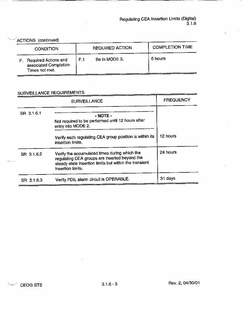
Regulating CEA Insertion Limits (Digital) 3.1.6
ACTIONS (continued)
CONDITION REQUIRED ACTION COMPLETION TIME
F. Required Actions and F.1 Be in MODE 3. 6 hours
associated Completion Times not met.
SURVEILLANCE REQUIREMENTS
SURVEILLANCE FREQUENCY
SR 3.1.6.1 ---- ---
- NOTE Not required to be performed until 12 hours after entry into MODE 2.
-------------------------------------------
Verify each regulating CEA group position is within its 12 hours
insertion limits.
SR 3.1.6.2 Verify the accumulated times during which the 24 hours
regulating CEA groups are inserted beyond the steady state insertion limits but within the transient insertion limits.
SR 3.1.6.3 Verify PDIL alarm circuit is OPERABLE. 31 days
Rev. 2, 04/30/01CEOG STS 3.1.6- 3

Part Length CEA Insertion Limits (Digital) 3.1.7
3.1 REACTIVITY CONTROL SYSTEMS
3.1.7 Part Length Control Element Assembly (CEA) Insertion Limits (Digital)
LCO 3.1.7
APPLICABILITY:
The part length Control Element Assembly (CEA) groups shall be limited to the insertion limits specified in the COLR.
MODE 1 > 20% RTP.
ACTIONS
- NOTE This LCO not applicable while exercising part length CEAs.
CONDITION REQUIRED ACTION COMPLETION TIME
A. Part length CEA groups A.1 Restore part length CEA 2 hours inserted beyond the groups to within the limit. transient insertion limit.
OR
A.2 Reduce THERMAL 2 hours POWER to less than or equal to that fraction of RTP specified in the COLR.
B. Part length CEA groups B.1 Restore part length CEA 2 hours inserted between the groups to within the long long term steady state term steady state insertion insertion limit and the limit. transient insertion limit for intervals -7 effective full power days (EFPD) per 30 EFPD or 2 14 EFPD per 365 EFPD interval.
Rev. 2, 04/30/01CEOG STS 3.1.7- 1

Part Length CEA Insertion Limits (Digital) 3.1.7
ACTIONS (continued)
CONDITION REQUIRED ACTION COMPLETION TIME
C. Required Action and C.1 Reduce THERMAL 4 hours associated Completion POWER to _ 20% RTP. Time of Condition B not met.
SURVEILLANCE REQUIREMENTS
SURVEILLANCE FREQUENCY
SR 3.1.7.1 Verify part length CEA group position. 12 hours
Rev. 2, 04/30/01CEOG STS 3.1.7- 2

Special Test Exception - SDM (Digital) 3.1.8
3.1 REACTIVITY CONTROL SYSTEMS
3.1.8 Special Test Exceptions (STE) - SHUTDOWN MARGIN (SDM) (Digital)
During performance of PHYSICS TESTS, the requirements of:
LCO 3.1.1, "SHUTDOWN MARGIN (SDM)-Tavg > 200'F," and LCO 3.1.6, "Regulating Control Element Assembly (CEA) Insertion Limits,"
may be suspended for measurement of CEA worth and SDM, provided shutdown reactivity equivalent to at least the highest estimated CEA worth (of those CEAs actually withdrawn) is available for trip insertion.
APPLICABILITY: MODES 2 and 3 during PHYSICS TESTS.
- NOTE Operation in MODE 3 shall be limited to 6 consecutive hours.
ACTIONS
CONDITION REQUIRED ACTION COMPLETION TIME
A. Any full length CEA not A.1 Initiate boration to restore 15 minutes fully inserted and less required shutdown than the required reactivity. shutdown reactivity available for trip insertion.
OR
All full length CEAs inserted and the reactor subcritical by less than the above required shutdown reactivity equivalent.
Rev. 2, 04/30/01
LCO 3.1.8
CEOG STS 3.1.8- 1

Special Test Exceptions - MODES 1 and 2 (Digital) 3.1.9
3.1 REACTIVITY CONTROL SYSTEMS
3.1.9 Special Test Exceptions (STE) - MODES 1 and 2 (Digital)
During performance of PHYSICS TESTS, the requirements of:
LCO 3.1.3, LCO 3.1.4, LCO 3.1.5, LCO 3.1.6, LCO 3.1.7, LCO 3.2.2, LCO 3.2.3,
"Moderator Temperature Coefficient," "Control Element Assembly Alignment," "Shutdown Control Element Assembly Insertion Limits," "Regulating Control Element Assembly Insertion Limits," "Part Length Control Element Assembly Insertion Limits," "Planar Radial Peaking Factors," and "AZIMUTHAL POWER TILT,"
may be suspended, provided THERMAL POWER is restricted to the test power plateau, which shall not exceed 85% RTP.
APPLICABILITY: MODES 1 and 2 during PHYSICS TESTS.
ACTIONS
CONDITION REQUIRED ACTION COMPLETION TIME
A. Test power plateau A.1 Reduce THERMAL 15 minutes exceeded. POWER to less than or
equal to the test power plateau.
B. Required Action and B.1 Suspend PHYSICS 1 hour associated Completion TESTS. Time not met.
SURVEILLANCE REQUIREMENTS
SURVEILLANCE FREQUENCY
SR 3.1.9.1 Verify THERMAL POWER equal to or less than the 1 hour test power plateau.
Rev. 2, 04/30/01
LCO 3.1.9
CEOG STS 3.1.9- 1

LHR (Digital) 3.2.1
3.2 POWER DISTRIBUTION LIMITS
3.2.1 Linear Heat Rate (LHR) (Digital)
LCO 3.2.1 LHR shall not exceed the limits specified in the COLR.
APPLICABILITY: MODE 1 with THERMAL POWER > 20% RTP.
ACTIONS
CONDITION REQUIRED ACTION COMPLETION TIME
A. Core Operating Limit A.1 Restore LHR to within 1 hour Supervisory System limits. (COLSS) calculated core power exceeds the COLSS calculated core power operating limit based on LHR.
B. LHR not within region of B.1 Determine trend in LHR. Once per 15 minutes acceptable operation when the COLSS is out AND of service.
B.2.1 With an adverse trend, 1 hour restore LHR to within limit.
OR
B.2.2 With no adverse trend, 4 hours restore LHR to within limits.
C. Required Action and C.1 Reduce THERMAL 6 hours associated Completion POWER to • 20% RTP. Time not met.
Rev. 2, 04/30/01CEOG STS 3.2.1 - 1

LHR (Digital) 3.2.1
SURVEILLANCE REQUIREMENTS
SURVEILLANCE FREQUENCY
SR 3.2.1.1 - NOTE
Only required to be met when COLSS is out of service. With COLSS in service, LHR is continuously monitored. ----------------------------------------------
Verify LHR, as indicated on each OPERABLE local 2 hours power density channel, is within its limit.
SR 3.2.1.2 Verify the COLSS margin alarm actuates at a 31 days THERMAL POWER equal to or less than the core power operating limit based on LHR.
Rev. 2, 04/30/01CEOG STS 3.2.1- 2

Fxy (Digital) 3.2.2
3.2 POWER DISTRIBUTION LIMITS
3.2.2 Planar Radial Peaking Factors (F4) (Digital)
LCO 3.2.2
APPLICABILITY:
The measured Planar Radial Peaking Factors (Fm) shall be equal to or less than the Planar Radial Peaking Factors (FC). (These factors are used in the Core Operating Limit Supervisory System (COLSS) and in the Core Protection Calculators (CPCs)).
MODE 1 with THERMAL POWER > 20% RTP.
ACTIONS
CONDITION REQUIRED ACTION COMPLETION TIME
A. Fm > FC. A.1.1 Adjust addressable CPC 6 hours constants to increase the multiplier applied to planar radial peaking by a factor
M F/I. F.
AND
A.1.2 Maintain a margin to the 6 hours COLSS operating limits of [(Fm / FC)-l.0] x 100%.
OR
A.2 Adjust the affected Fc 6 hours used in the COLSS and CPCs to a value greater than or equal to the measured Fmx
OR
A.3 Reduce THERMAL 6 hours POWER to _ 20% RTP.
Rev. 2, 04/30/01CEOG STS 3.2.2- 1

Fxy (Digital) 3.2.2
SURVEILLANCE REQUIREMENTS
SLiRVEILLANCE
Verify measured Fm obtained using the Incore Detector System is equal to or less than the value of Fc used in the COLSS and CPCs.
FREQUENCY
Once after each fuel loading with THERMAL POWER > 40% RTP but prior to operations above 70% RTP
AND
31 EFPD thereafter
Rev. 2, 04/30/01
SR 3.2.2.1
CEOG STS 3.2.2- 2

Tq (Digital) 3.2.3
3.2 POWER DISTRIBUTION LIMITS
3.2.3 AZIMUTHAL POWER TILT (Tq) (Digital)
LCO 3.2.3
APPLICABILITY:
The measured Tq shall be less than or equal to the Tq allowance used in the core protection calculators (CPCs).
MODE 1 with THERMAL POWER > 20% RTP.
ACTIONS
CONDITION REQUIRED ACTION COMPLETION TIME
A. Measured Tq greater A.1 Restore measured Tq. 2 hours than the allowance used in the CPCs and OR •[0.10].
A.2 Adjust the Tq allowance in 2 hours the CPCs to greater than or equal to the measured value.
B. Measured Tq > [0.10]. - NOTE-
All subsequent Required Actions must be completed if power reduction commences prior to restoring Tq to • [0.10].
B.1 Reduce THERMAL 4 hours
POWER to _ 50% RTP.
AND
B.2 Reduce Linear Power 16 hours Level - High trip setpoints to :g 55% RTP.
AND
Rev. 2, 04/30/01CEOG STS 3.2.3- 1

Tq (Digital)
3.2.3
ACTIONS (continued)
CONDITION REQUIRED ACTION COMPLETION TIME
B.3 Restore the measured Tq Prior to increasing to less than the Tq THERMAL POWER allowance used in the CPCs. ---------
- NOTE Correct the cause of the out of limit condition prior to increasing THERMAL POWER. Subsequent power operation > 50% RTP may proceed provided that the measured Tq is verified • [0.10] at least once per hours for 12 hours, or until verified at > 95% RTP
C. Required Actions and C.1 Reduce THERMAL 6 hours associated Completion POWER to _ 20%. Times not met.
SURVEILLANCE REQUIREMENTS
SURVEILLANCE FREQUENCY
SR 3.2.3.1- ---------------------------- NOTES
Only required to be met when COLSS is out of service. With COLSS in service, this parameter is continuously monitored.
Calculate Tq and verify it is within the limit. 12 hours
SR 3.2.3.2 Verify COLSS azimuthal tilt alarm is actuated at a Tq 31 days value less than the Tq value used in the CPCs.
Rev. 2, 04/30/01CEOG STS 3.2.3- 2

Tq (Digital) 3.2.3
SURVEILLANCE REQUIREMENTS (continued)
SURVEILLANCE FREQUENCY
SR 3.2.3.3 Independently confirm the validity of the COLSS 31 EFPD calculated Tq by use of the incore detectors.
Rev. 2, 04/30/01CEOG STS 3.2.3- 3

DNBR (Digital) 3.2.4
3.2 POWER DISTRIBUTION LIMITS
3.2.4 Departure From Nucleate Boiling Ratio (DNBR) (Digital)
The DNBR shall be maintained by one of the following methods:
a. Maintaining Core Operating Limit Supervisory System (COLSS) calculated core power less than or equal to COLSS calculated core power operating limit based on DNBR (when COLSS is in service, and either one or both control element assembly calculators (CEACs) are OPERABLE),
b. Maintaining COLSS calculated core power less than or equal to COLSS calculated core power operating limit based on DNBR decreased by the allowance specified in the COLR (when COLSS is in service and neither CEAC is OPERABLE),
c. Operating within the region of acceptable operation of Figure 3.2.4-1 specified in the COLR using any operable core protection calculator (CPC) channel (when COLSS is out of service and either one or both CEACs are OPERABLE), or
d. Operating within the region of acceptable operation of Figure 3.2.4-2 specified in the COLR using any operable CPC channel (when COLSS is out of service and neither CEAC is OPERABLE).
APPLICABILITY: MODE 1 with THERMAL POWER > 20% RTP.
ACTIONS
CONDITION REQUIRED ACTION COMPLETION TIME
A. COLSS calculated core A.1 Restore the DNBR to 1 hour power not within limit, within limit.
B. DNBR outside the region B.1 [Determine trend in DNBR. Once per 15 minutes] of acceptable operation when COLSS is out of AND service.
Rev. 2, 04/30/01
LCO 3.2.4
CEOG STS 3.2.4- 1

DNBR (Digital) 3.2.4
ACTIONS (continued)
CONDITION REQUIRED ACTION COMPLETION TIME
B.2.1 With an adverse trend, 1 hour restore DNBR to within limit.
OR
B.2.2 With no adverse trend, 4 hours restore DNBR to within limit.
C. Required Action and C.1 Reduce THERMAL 6 hours associated Completion POWER to • 20% RTP. Time not met.
SURVEILLANCE REQUIREMENTS
SURVEILLANCE FREQUENCY
SR 3.2.4.1- -------------------------NOTE
Only required to be met when COLSS is out of service. With COLSS in service, this parameter is continuously monitored.
--------- --------------------------Verify DNBR, as indicated on all OPERABLE DNBR 2 hours channels, is within the limit of Figure 3.2.4-1 or 3.2.42 of the COLR, as applicable.
SR 3.2.4.2 Verify COLSS margin alarm actuates at a THERMAL POWER level equal to or less than the core power 31 days operating limit based on DNBR.
Rev. 2, 04/30/01CEOG STS 3.2.4- 2

RPS Instrumentation - Operating (Digital) 3.3.1
3.3 INSTRUMENTATION
3.3.1 Reactor Protective System (RPS) Instrumentation - Operating (Digital)
LCO 3.3.1
APPLICABILITY:
Four RPS trip and bypass removal channels for each Function in Table 3.3.1-1 shall be OPERABLE.
According to Table 3.3.1-1.
ACTIONS
- NOTE Separate Condition entry is allowed for each RPS Function.
CONDITION REQUIRED ACTION COMPLETION TIME
A. One or more Functions A.1 Place channel in bypass or 1 hour with one automatic RPS trip. trip channel inoperable.
AND
A.2 Restore channel to Prior to entering OPERABLE status. MODE 2 following
next MODE 5 entry
B. One or more Functions B.1 with two automatic RPS - NOTE trip channels inoperable. LCO 3.0.4 is not
applicable.
Place one channel in 1 hour bypass and the other in trip.
C. One or more Functions C.1 Disable bypass channel. 1 hour with one automatic bypass removal channel OR inoperable.
Rev. 2, 04/30/01CEOG STS 3.3.1 - 1

RPS Instrumentation - Operating (Digital) 3.3.1
ACTIONS (continued)
CONDITION REQUIRED ACTION COMPLETION TIME
C.2.1 Place affected automatic 1 hour trip channel in bypass or trip.
AND
C.2.2 Restore bypass removal Prior to entering channel and associated MODE 2 following automatic trip channel to next MODE 5 entry OPERABLE status.
D. One or more Functions with two automatic - NOTE bypass removal LCO 3.0.4 is not channels inoperable, applicable.
D.1 Disable bypass channels. 1 hour
OR
D.2 Place one affected 1 hour automatic trip channel in bypass and place the other in trip.
E. One or more core E.1 Perform CHANNEL 12 hours protection calculator FUNCTIONAL TEST on (CPC) channels with a affected CPC. cabinet high temperature alarm.
F. One or more CPC F.1 Perform CHANNEL 24 hours channels with three or FUNCTIONAL TEST on more autorestarts during affected CPC. a 12 hour period.
G. Required Action and G.1 Be in MODE 3. 6 hours associated Completion Time not met.
Rev. 2, 04/30/01CEOG STS 3.3.1- 2

RPS Instrumentation - Operating (Digital) 3.3.1
SURVEILLANCE REQUIREMENTS
- NOTE Refer to Table 3.3.1-1 to determine which SR shall be performed for each RPS Function.
SURVEILLANCE FREQUENCY
SR 3.3.1.1 Perform a CHANNEL CHECK of each RPS 12 hours instrument channel except Loss of Load.
SR 3.3.1.2 - NOTE
Not required to be performed until 12 hours after THERMAL POWER Ž 70% RTP.
Verify total Reactor Coolant System (RCS) flow rate 12 hours as indicated by each CPC is less than or equal to the RCS total flow rate.
If necessary, adjust the CPC addressable constant flow coefficients such that each CPC indicated flow is less than or equal to the RCS flow rate.
SR 3.3.1.3 Check the CPC autorestart count. 12 hours
SR 3.3.1.4 -NOTES
1. Not required to be performed until 12 hours after THERMAL POWER > 20% RTP.
2. The daily calibration may be suspended during PHYSICS TESTS, provided the calibration is performed upon reaching each major test power plateau and prior to proceeding to the next major test power plateau.
Perform calibration (heat balance only) and adjust 24 hours the linear power level signals and the CPC addressable constant multipliers to make the CPC AT power and CPC nuclear power calculations agree with the calorimetric, if the absolute difference is > [2]%.
Rev. 2, 04/30/01CEOG STS 3.3.1- 3

RPS Instrumentation - Operating (Digital) 3.3.1
SURVEILLANCE REQUIREMENTS (continued)
SURVEILLANCE FREQUENCY
SR 3.3.1.5 - NOTE
Not required to be performed until 12 hours after THERMAL. POWER z 70% RTP. ----------------------------------------------
Verify total RCS flow rate indicated by each CPC is 31 days less than or equal to the RCS flow determined by calorimetrc calculations.
S R 3 .3 .1.6 -------------------------------------------------------NOTE
Not required to be performed until 12 hours after THERMAL. POWER ; 15% RTP. ----------------------------------------------
Verify linear power subchannel gains of the excore 31 days detectors are consistent with the values used to establish the shape annealing matrix elements in the CPCs.
SR 3.3.1.7 - NOTES
1. The CPC CHANNEL FUNCTIONAL TEST shall include verification that the correct values of addressable constants are installed in each OPERABLE CPC.
2. Not required to be performed for logarithmic power level channels until 2 hours after reducing logari(hmic power below 1 E-4% and only if reactor trip circuit breakers (RTCBs) are closed.
---- --------------------
Perform CHANNEL FUNCTIONAL TEST on each 92 days channel except Loss of Load and power range neutron flux.
SR 3.3.1.8- -----------NOTE
Neutron detectors are excluded from the CHANNEL CALIBRATION. ----------------.------------------------------
Perform CHANNEL CALIBRATION of the power 92 days range neutron flux channels.
Rev. 2, 04/30/01CEOG STS 3.3.1- 4
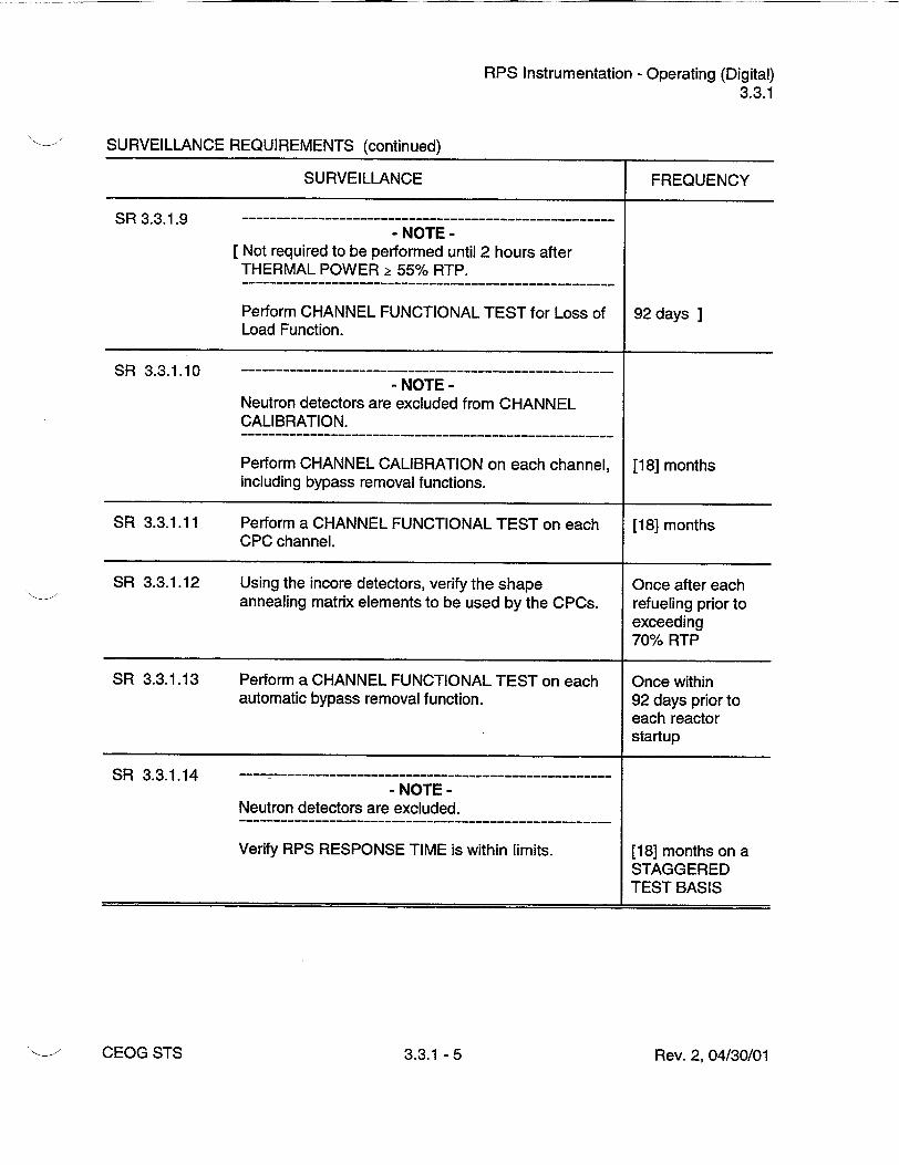
RPS Instrumentation - Operating (Digital) 3.3.1
SURVEILLANCE REQUIREMENTS (continued)
SURVEILLANCE FREQUENCY
SR 3.3.1.9 -NOTE
[Not required to be performed until 2 hours after THERMAL POWER > 55% RTP.
Perform CHANNEL FUNCTIONAL TEST for Loss of 92 days ] Load Function.
SR 3.3.1.10 - NOTE
Neutron detectors are excluded from CHANNEL CALIBRATION.
Perform CHANNEL CALIBRATION on each channel, [18] months including bypass removal functions.
SR 3.3.1.11 Perform a CHANNEL FUNCTIONAL TEST on each [18] months CPC channel.
SR 3.3.1.12 Using the incore detectors, verify the shape Once after each annealing matrix elements to be used by the CPCs. refueling prior to
exceeding 70% RTP
SR 3.3.1.13 Perform a CHANNEL FUNCTIONAL TEST on each Once within automatic bypass removal function. 92 days prior to
each reactor startup
SR 3.3.1.14 -------------------- NOTE
Neutron detectors are excluded.
Verify RPS RESPONSE TIME is within limits. [18] months on a STAGGERED TEST BASIS
Rev. 2, 04/30/01CEOG STS 3.3.1 - 5
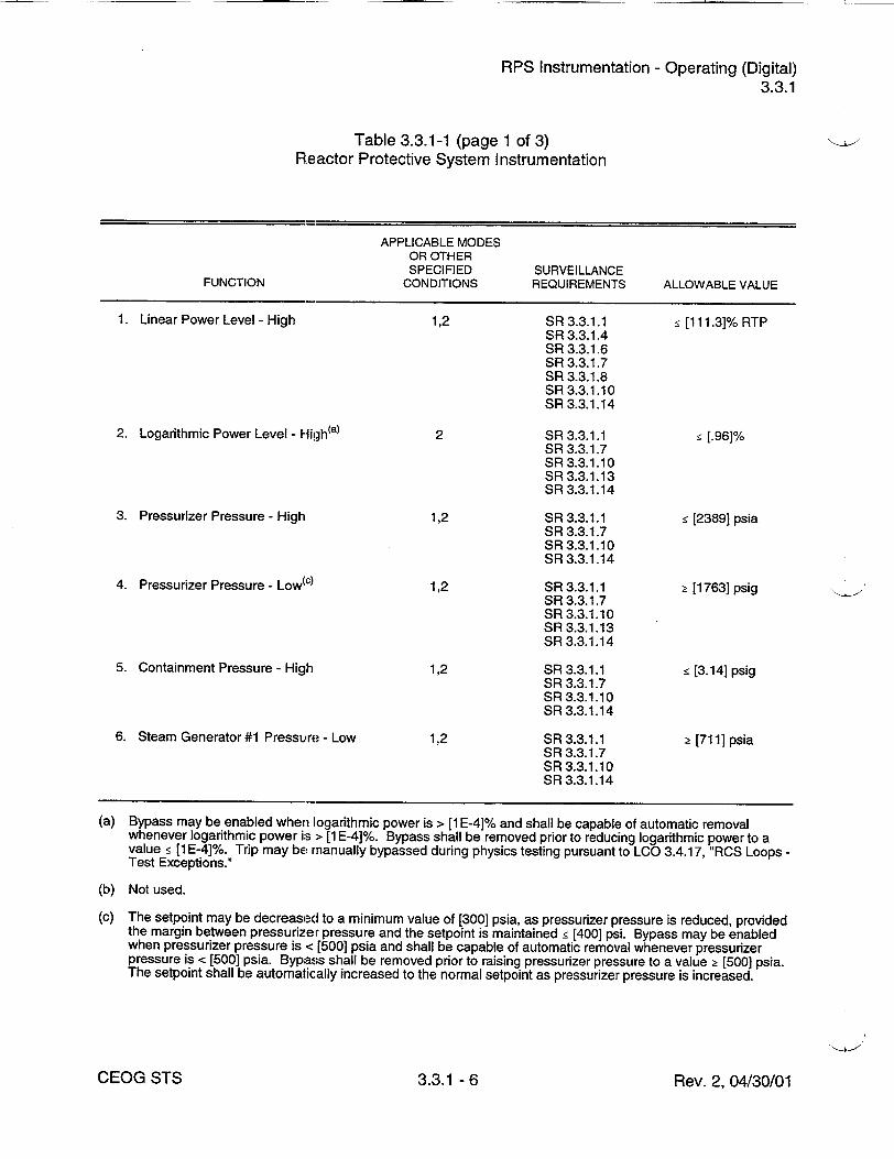
RPS Instrumentation - Operating (Digital) 3.3.1
Table 3.3.1-1 (page 1 of 3) Reactor Protective System Instrumentation
APPLICABLE MODES OR OTHER SPECIFIED SURVEILLANCE
FUNCTION CONDITIONS REQUIREMENTS ALLOWABLE VALUE
1. Linear Power Level - High 1,2 SR 3.3.1.1 [ 1111.31% RTP SR 3.3.1.4 SR 3.3.1.6 SR 3.3.1.7 SR 3.3.1.8 SR 3.3.1.10 SR 3.3.1.14
2. Logarithmic Power Level - Higlh(a) 2 SR 3.3.1.1 • [.96]% SR 3.3.1.7 SR 3.3.1.10 SR 3.3.1.13 SR 3.3.1.14
3. Pressurizer Pressure - High 1,2 SR 3.3.1.1 ! [2389] psia SR 3.3.1.7 SR 3.3.1.10 SR 3.3.1.14
4. Pressurizer Pressure - Low(c) 1,2 SR 3.3.1.1 Ž [1763] psig SR 3.3.1.7 SR 3.3.1.10 SR 3.3.1.13 SR 3.3.1.14
5. Containment Pressure - High 1,2 SR 3.3.1.1 • [3.14] psig SR 3.3.1.7 SR 3.3.1.10 SR 3.3.1.14
6. Steam Generator #1 Pressure - Low 1,2 SR 3.3.1.1 _ [711] psia SR 3.3.1.7 SR 3.3.1.10 SR 3.3.1.14
(a) Bypass may be enabled when logarithmic power is > [1 E-4]% and shall be capable of automatic removal whenever logarithmic power is > [1 E-4]%. Bypass shall be removed prior to reducing logarithmic power to a value ! [1 E-4]%. Trip may be manually bypassed during physics testing pursuant to LCO 3.4.17, "RCS Loops Test Exceptions."
(b) Not used.
(c) The setpoint may be decreased to a minimum value of [300] psia, as pressurizer pressure is reduced, provided the margin between pressurizer pressure and the setpoint is maintained g [400] psi. Bypass may be enabled when pressurizer pressure is < [500] psia and shall be capable of automatic removal whenever pressurizer pressure is < [500] psia. Bypass shall be removed prior to raising pressurizer pressure to a value 2t [500] psia. The setpoint shall be automatically increased to the normal setpoint as pressurizer pressure is increased.
Rev. 2, 04/30/01CEOG STS 3.3.1 - 6

RPS Instrumentation - Operating (Digital) 3.3.1
Table 3.3.1-1 (page 2 of 3) Reactor Protective System Instrumentation
APPLICABLE MODES OR OTHER SPECIFIED SURVEILLANCE
FUNCTION CONDITIONS REQUIREMENTS ALLOWABLE VALUE
7. Steam Generator #2 Pressure - Low 1,2 SR 3.3.1.1 Ž [711] psia SR 3.3.1.7 SR 3.3.1.10 SR 3.3.1.14
8. Steam Generator #1 Level - Low 1,2 SR 3.3.1.1 • [24.23]% SR 3.3.1.7 SR 3.3.1.10 SR 3.3.1.14
9. Steam Generator #2 Level - Low 1,2 SR 3.3.1.1 Ž [24.23]% SR 3.3.1.7 SR 3.3.1.10 SR 3.3.1.14
10. Steam Generator #1 Level- High 1,2 SR 3.3.1.1 • [90.74]% SR 3.3.1.7 SR 3.3.1.10 SR 3.3.1.14
11. Steam Generator #2 Level - High 1,2 SR 3.3.1.1 • [90.74]% SR 3.3.1.7 SR 3.3.1.10 SR 3.3.1.14
[12. Reactor Coolant FI.r, Steam 1,2 SR 3.3.1.1 Ramp: • [0.231] Generator #1 - Low SR 3.3.1.7 psid/sec.
SR 3.3.1.10 Floor: 2t [12.1] psid [SR 3.3.1.13] Step: • [7.231] psid] SR 3.3.1.14
[13. Reactor Coolant Flog, Steam 1,2 SR 3.3.1.1 Ramp: • [0.231] Generator #2 - Low SR 3.3.1.7 psid/sec.
SR 3.3.1.10 Floor: 2 [12.1] psid [SR 3.3.1.13] Step: • [7.231] psid] SR 3.3.1.14
(d) Bypass may be enabled when logarithmic power is < [1 E-04]% and shall be capable of automatic removal whenever logarithmic power is < [1 E-4]%. Bypass shall be removed prior to raising logarithmic power to a value Ž[1E-4]%. During testing pursuant LCO 3.4.17, bypass may be enabled when THERMAL POWER is < [5]% RTP and shall be capable of automatic removal whenever THERMAL POWER is < [5]% RTP. Bypass shall be removed above 5% RTP.
Rev. 2, 04/30/01CEOG STS 3.3.1- 7

RPS Instrumentation - Operating (Digital) 3.3.1
Table 3.3.1-1 (page 3 of 3) Reactor Protective System Instrumentation
APPLICABLE MODES OR OTHER SPECIFIED SURVEILLANCE
FUNCTION CONDITIONS REQUIREMENTS ALLOWABLE VALUE
[14. Loss of Load (turbine stop valve 1 SR 3.3.1.9 Ž [100] psig] control oil pressure)ýe) SR 3.3.1.10
[SR 3.3.1.13]
15. Local Power Density - High(d) 1,2 SR 3.3.1.1 <[21.0] kW/ft SR 3.3.1.2 SR 3.3.1.3 SR 3.3.1.4 SR 3.3.1.5 SR 3.3.1.7 SR 3.3.1.10 SR 3.3.1.11 SR 3.3.1.12 SR 3.3.1.13 SR 3.3.1.14
16. Departure From Nucleate Boiling 1,2 SR 3.3.1.1 Ž [1.31] Ratio (DNBR) - Low~d, SR 3.3.1.2
SR 3.3.1.3 SR 3.3.1.4 SR 3.3.1.5 SR 3.3.1.7 SR 3.3.1.10 SR 3.3.1.11 SR 3.3.1.12 SR 3.3.1.13 SR 3.3.1.14
(d) Bypass may be enabled when logarithmic power is < [1 E-04]% and shall be capable of automatic removal whenever logarithmic power is < [1 E-4]%. Bypass shall be removed prior to raising logarithmic power to a value >[1 E-4]%. During testing pursuant LCO 3.4.17, bypass may be enabled when THERMAL POWER is < [5]% RTP and shall be capable of automatic removal whenever THERMAL POWER is < [5]% RTP. Bypass shall be removed above 5% FITrP.
(e) Bypass may be enabled when -rHERMAL POWER is < [55]% RTP and shall be capable of automatic removal whenever THERMAL POWER is < [55]% RTP. Bypass shall be removed prior to raising THERMAL POWER to a value 2[551% RTP.
Rev. 2, 04/30/01CEOG STS 3.3.1 - 8

RPS Instrumentation - Shutdown (Digital) 3.3.2
3.3 INSTRUMENTATION
3.3.2 Reactor Protective System (RPS) Instrumentation - Shutdown (Digital)
LCO 3.3.2
APPLICABILITY:
Four RPS Logarithmic Power Level - High trip channels and associated instrument and bypass removal channels shall be OPERABLE.
MODES 3, 4, and 5, with any reactor trip circuit breakers (RTCBs) closed and any control element assembly capable of being withdrawn.
- NOTE Bypass may be enabled when logarithmic power is > [1 E-4]% and shall be capable of automatic removal whenever logarithmic power is > [1 E-4]%. Bypass shall be removed prior to reducing logarithmic power to a value _< [1 E-4]%. Trip may be manually bypassed during physics testing pursuant to LCO 3.4.17, "RCS Loops - Test Exceptions."
ACTIONS
CONDITION REQUIRED ACTION COMPLETION TIME
A. One RPS logarithmic A.1 Place channel in bypass or 1 hour power level trip channel trip. inoperable.
AND
A.2 Restore channel to Prior to entering OPERABLE status. MODE 2 following
next MODE 5 entry
B. Two RPS logarithmic B.1 power level trip channels - NOTE inoperable. LCO 3.0.4 is not
applicable.
Place one channel in 1 hour bypass and place the other in trip.
Rev. 2, 04/30/01CEOG STS 3.3.2- 1

RPS Instrumentation - Shutdown (Digital) 3.3.2
ACTIONS (continued)
CONDITION REQUIRED ACTION COMPLETION TIME
C. One automatic bypass C.1 Disable bypass channel. 1 hour removal channel inoperable. OR
C.2.1 Place affected automatic 1 hour trip channel in bypass or trip.
AND
C.2.2 Restore bypass removal Prior to entering channel and associated MODE 2 following automatic trip channel to next MODE 5 entry OPERABLE status.
D. Two automatic bypass removal channels - NOTE inoperable. LCO 3.0.4 is not
applicable.
D.1 Disable bypass channels. 1 hour
OR
D.2 Place one affected 1 hour automatic trip channel in bypass and place the other in trip.
E. Required Action and E.1 Open all RTCBs. 1 hour associated Completion Time not met.
SURVEILLANCE REQUIREMENTS
SURVEILLANCE FREQUENCY
SR 3.3.2.1 Perform a CHANNEL CHECK of each logarithmic 12 hours power channel.
Rev. 2, 04/30/01CEOG STS 3.3.2- 2

RPS Instrumentation - Shutdown (Digital) 3.3.2
SURVEILLANCE REQUIREMENTS (continued)
SURVEILLANCE FREQUENCY
SR 3.3.2.2 Perform a CHANNEL FUNCTIONAL TEST on each 92 days logarithmic power channel.
SR 3.3.2.3 Perform a CHANNEL FUNCTIONAL TEST on each Once within automatic bypass removal function. 92 days prior to
each reactor startup
SR 3.3.2.4 - NOTE
Neutron detectors are excluded from CHANNEL CALIBRATION.
Perform a CHANNEL CALIBRATION on each [18] months logarithmic power channel, including bypass removal function with Allowable Value for trip channels _< [.93]%.
SR 3.3.2.5 Verify RPS RESPONSE TIME is within limits. [18] months on a STAGGERED TEST BASIS
Rev. 2, 04/30/01CEOG STS 3.3.2- 3

CEACs (Digital) 3.3.3
3.3 INSTRUMENTATION
3.3.3 Control Element Assembly Calculators (CEACs) (Digital)
LCO 3.3.3
APPLICABILITY:
Two CEACs shall be OPERABLE.
MODES 1 and 2.
ACTIONS
CONDITION REQUIRED ACTION COMPLETION TIME
A. One CEAC inoperable. A.1 Perform SR 3.1.4.1. Once per 4 hours
AND
A.2 Restore CEAC to 7 days OPERABLE status.
B. Required Action and B.1 Verify the departure from 4 hours associated Completion nucleate boiling ratio Time of Condition A not requirement of LCO 3.2.4, met. "Departure from Nucleate
Boiling Ratio (DNBR)," is OR met [and the Reactor
Power Cutback System is Both CEACs inoperable, disabled].
AND
Rev. 2, 04/30/01CEOG STS 3.3.3- 1

CEACs (Digital) 3.3.3
ACTIONS (continued)
CONDITION REQUIRED ACTION COMPLETION TIME
B.2 Verify all full length and 4 hours part length control element assembly (CEA) groups are fully withdrawn and maintained fully withdrawn, except during Surveillance testing pursuant to SR 3.1.4.3 [or for control, when CEA group #6 may be inserted to a maximum of 127.5 inches].
AND
B.3 Verify the "RSPT/CEAC 4 hours Inoperable" addressable constant in each core protection calculator (CPC) is set to indicate that both CEACs are inoperable.
AND
B.4 Verify the Control Element 4 hours Drive Mechanism Control System is placed in "OFF" and maintained in "OFF," except during CEA motion permitted by Required Action B.2.
AND
B.5 Perform SR 3.1.4.1. Once per4 hours
Rev. 2, 04/30/01
C. Receipt of a CPC C.1 Perform CHANNEL 12 hours channel B or C cabinet FUNCTIONAL TEST on high temperature alarm. affected CEAC(s).
CEOG STS 3.3.3- 2

CEACs (Digital) 3.3.3
ACTIONS (continued)
CONDITION REQUIRED ACTION COMPLETION TIME
D. One or two CEACs with D.1 Perform CHANNEL 24 hours three or more FUNCTIONAL TEST on autorestarts during a affected CEAC. 12 hours period.
E. Required Action and E.1 Be in MODE 3. 6 hours associated Completion Time of Condition B, C, or D not met.
SURVEILLANCE REQUIREMENTS
SURVEILLANCE FREQUENCY
SR 3.3.3.1 Perform a CHANNEL CHECK. 12 hours
SR 3.3.3.2 Check the CEAC autorestart count. 12 hours
SR 3.3.3.3 Perform a CHANNEL FUNCTIONAL TEST. 92 days
SR 3.3.3.4 Perform a CHANNEL CALIBRATION. [18] months
SR 3.3.3.5 Perform a CHANNEL FUNCTIONAL TEST. [18] months
SR 3.3.3.6 Verify the isolation characteristics of each CEAC [18] months isolation amplifier and each optical isolator for CEAC to CPC data transfer.
Rev. 2, 04/30/01CEOG STS 3.3.3- 3

RPS Logic and Trip Initiation (Digital) 3.3.4
3.3 INSTRUMENTATION
3.3.4 Reactor Protective System (RPS) Logic and Trip Initiation (Digital)
LCO 3.3.4
APPLICABILITY:
Six channels of RPS Matrix Logic, four channels of RPS Initiation Logic, [four channels of reactor trip circuit breakers (RTCBs),] and four channels of Manual Trip shall be OPERABLE.
MODES 1 and 2, MODES 3, 4, and 5, with any RTCBs closed and any control element
assemblies capable of being withdrawn.
ACTIONS
CONDITION REQUIRED ACTION COMPLETION TIME A. One Matrix Logic A.1 Restore channel(s) to 48 hours
channel inoperable. OPERABLE status.
OR
Three Matrix Logic channels inoperable due to a common power source failure deenergizing three matrix power supplies.
B. One channel of Manual B.1 Open the affected RTCBs. 1 hour Trip, RTCBs, or Initiation Logic inoperable in MODE 1 or 2.
C. One channel of Manual C.1 Open the affected RTCBs. 48 hours Trip, RTCBs, or Initiation Logic inoperable in MODE 3, 4, or 5.
D. Two channels of Manual D.1 Open the affected RTCBs. Immediately Trip, RTCBs, or Initiation Logic affecting the same trip leg inoperable.
3.3.4- 1CEOG STS Rev. 2, 04/30/01

RPS Logic and Trip Initiation (Digital) 3.3.4
ACTIONS (continued)
CONDITION REQUIRED ACTION COMPLETION TIME
E. Required Action and E.1 Be in MODE 3. 6 hours associated Completion Time of Condition A, B, AND or D not met.
E.2 Open all RTCBs. 6 hours OR
One or more Functions with more than one Manual Trip, Matrix Logic, Initiation Logic, or RTCB channel inoperable for reasons other than Condition A or D.
SURVEILLANCE REQUIREMENTS
SURVEILLANCE FREQUENCY
SR 3.3.4.1 Perform a CHANNEL FUNCTIONAL TEST on each [31] days RTCB channel.
SR 3.3.4.2 Perform a CHANNEL FUNCTIONAL TEST on each [92] days RPS Logic channel.
SR 3.3.4.3 Perform a CHANNEL FUNCTIONAL TEST, including [18] months separate verification of the undervoltage and shunt trips, on each RTCB.
SR 3.3.4.4 Perform a CHANNEL FUNCTIONAL TEST on each Once within RPS Manual Trip channel. 7 days prior to
each reactor startup
Rev. 2, 04/30/01CEOG STS 3.3.4- 2

ESFAS Instrumentation (Digital) 3.3.5
3.3 INSTRUMENTATION
3.3.5 Engineered Safety Features Actuation System (ESFAS) Instrumentation (Digital)
LCO 3.3.5
APPLICABILITY:
Four ESFAS trip and bypass removal channels for each Function in Table 3.3.5-1 shall be OPERABLE.
According to Table 3.3.5-1.
ACTIONS
- NOTE Separate Condition entry is allowed for each ESFAS Function.
CONDITION REQUIRED ACTION COMPLETION TIME
A. One or more Functions A.1 Place channel in bypass or 1 hour with one automatic trip. ESFAS trip channel inoperable. AND
A.2 Restore channel to Prior to entering OPERABLE status. MODE 2 following
next MODE 5 entry
B. One or more Functions B.1------------------with two automatic - NOTE ESFAS trip channels LCO 3.0.4 is not inoperable, applicable.
Place one channel in 1 hour bypass and the other in trip.
C. One or more Functions C.1 Disable bypass channel. 1 hour with one automatic bypass removal channel OR inoperable.
Rev. 2, 04/30/01CEOG STS 3.3.5- 1

ESFAS Instrumentation (Digital) 3.3.5
ACTIONS (continued)
CONDITION REQUIRED ACTION COMPLETION TIME
C.2.1 Place affected automatic 1 hour trip channel in bypass or trip.
AND
C.2.2 Restore bypass removal Prior to entering channel and associated MODE 2 following automatic trip channel to next MODE 5 entry OPERABLE status.
D. One or more Functions with two automatic - NOTE bypass removal LCO 3.0.4 is not channels inoperable, applicable.
D.1 Disable bypass channels. 1 hour
OR
D.2 Place one affected 1 hour automatic trip channel in bypass and place the other in trip.
E. Required Action and E.1 Be in MODE 3. 6 hours associated Completion Time not met. AND
E.2 Be in MODE 4. [12] hours
Rev. 2, 04/30/01CEOG STS 3.3.5- 2

ESFAS Instrumentation (Digital) 3.3.5
SURVEILLANCE REQUIREMENTS
SURVEILLANCE FREQUENCY
SR 3.3.5.1 Perform a CHANNEL CHECK of each ESFAS 12 hours channel.
SR 3.3.5.2 Perform a CHANNEL FUNCTIONAL TEST of each 92 days ESFAS channel.
SR 3.3.5.3 Perform a CHANNEL CALIBRATION of each ESFAS [18] months channel, including bypass removal functions.
SR 3.3.5.4 Verify ESF RESPONSE TIME is within limits. [18] months on a STAGGERED TEST BASIS
SR 3.3.5.5 Perform a CHANNEL FUNCTIONAL TEST on each Once within automatic bypass removal channel. 92, days prior to
each reactor startup
Rev. 2, 04/30/01CEOG STS 3.3.5- 3

ESFAS Instrumentation (Digital) 3.3.5
Table 3.3.5-1 (page 1 of 2) Engineered Safety Features Actuation System Instrumentation
APPLICABLE MODES OR OTHER
SPECIFIED FUNCTION CONDITIONS ALLOWABLE VALUE
1. Safety Injection Actuation Signal(a)
a. Containment Pressure - High 1,2,3 < [3.14] psig
b. Pressurizer Pressure - Low(b) 1,2,3 Ž [1763] psia
2. Containment Spray Actuation Signal
a. Containment Pressure - High High 1,2,3 • [16.83] psia
b. Automatic SIAS 1,2,3 NA
3. Containment Isolation Actuation Signal
a. Containment Pressure - High 1,2,3 : [3.14] psig
b. Pressurizer Pressure - Low(b) 1,2,3 Ž [1763] psia
4. Main Steam Isolation Signal
a. Steam Generator Pressure - Low(c) 1 ,2 [(d) 3 c > [711] psig
b. Containment Pressure - High 1 ,2 (d),3 (d) g [3.14] psig
5. Recirculation Actuation Signal
a. Refueling Water Storage Tank Level - Low 1,2,3 [> 17.73 and : 19.27]%
(a) Automatic SIAS also initiates a Containment Cooling Actuation Signal (CCAS).
(b) The setpoint may be decreased to a minimum value of [300] psia, as pressurizer pressure is reduced, provided the margin between pressurizer pressure and the setpoint is maintained • [400] psia. Trips may be bypassed when pressurizer pressure is < [400] psia. Bypass shall be automatically removed when pressurizer pressure is 2 [500] psia. The setpoint shall be automatically increased to the normal setpoint as pressurizer pressure is increased.
(c) The setpoint may be decreased as steam pressure is reduced, provided the margin between steam pressure and the setpoint is maintained r [200] psig. The setpoint shall be automatically increased to the normal setpoint as steam pressure is increased.
(d) The Main Steam Isolation Signal (MSIS) Function (Steam Generator Pressure - Low and Containment Pressure - High signals) is not required to be OPERABLE when all associated valves isolated by the MSIS Function are closed and [de-activated].
CEOG STS Rev. 2, 04/30/013.3.5- 4

ESFAS Instrumentation (Digital) 3.3.5
Table 3.3.5-1 (page 2 of 2) Engineered Safety Features Actuation System Instrumentation
APPLICABLE MODES OR OTHER SPECIFIED
FUNCTION CONDITIONS ALLOWABLE VALUE
6. Emergency Feedwater Actuation Signal SG #1 (EFAS-1)
a. Steam Generator Level - Low 1,2,3 Ž [24.23]%
b. SG Pressure Difference - High 1,2,3 • [66.25] psid
[ c. Steam Generator Pressure - Low 1,2,3 > [711] psig]
7. Emergency Feedwater Actuation Signal SG #2 (EFAS-2)
a. Steam Generator Level - Low 1,2,3 • [24.23]%
b. SG Pressure Difference - High 1,2,3 g [66.25] psid
[ c. Steam Generator Pressure - Low 1,2,3 '1> [711] psig ]
Rev. 2, 04/30/01CEOG STS 3.3.5- 5

ESFAS Logic and Manual Trip (Digital) 3.3.6
3.3 INSTRUMENTATION
3.3.6 Engineered Safety Features Actuation System (ESFAS) Logic and Manual Trip (Digital)
LCO 3.3.6
APPLICABILITY:
Six channels of ESFAS Matrix Logic, four channels of ESFAS Initiation Logic, two channels of Actuation Logic, and two channels of Manual Trip shall be OPERABLE for each Function in Table 3.3.6-1.
According to Table 3.3.6-1.
ACTIONS
- NOTE Separate Condition entry is allowed for each Function.
CONDITION REQUIRED ACTION COMPLETION TIME
A. - ----------- A.1 Restore channel to 48 hours - NOTE - OPERABLE status.
This action also applies when three Matrix Logic channels are inoperable due to a common power source failure deenergizing three matrix power supplies.
One or more Functions with one Matrix Logic channel inoperable.
B. One or more Functions B.1 Restore channel to 48 hours with one Manual Trip or OPERABLE status. Initiation Logic channel inoperable.
Rev. 2, 04/30/01CEOG STS 3.3.6- 1

ESFAS Logic and Manual Trip (Digital) 3.3.6
ACTIONS (continued)
CONDITION REQUIRED ACTION COMPLETION TIME
° C. One or more Functions C.1 Open at least one contact Immediately with two Initiation Logic in the affected trip leg of channels affecting the both ESFAS Actuation same trip leg inoperable. Logics.
AND
C.2 Restore channels to 48 hours OPERABLE status.
D. One or more Functions D.1 ---------------------------with one Actuation Logic - NOTE channel inoperable. One channel of Actuation
Logic may be bypassed for up to 1 hour for Surveillances, provided the other channel is OPERABLE.
Restore inoperable 48 hours channel to OPERABLE status.
E. Two Actuation Logic E.1 Be in MODE 3. 6 hours channels inoperable
AND OR
E.2 Be in MODE 4. [12] hours Required Action and associated Completion Time of Conditions, for Containment Spray Actuation Signal, Main Steam Isolation Signal, or Emergency Feedwater Actuation Signal not met.
CEOG STS 3.3.6- 2 Rev. 2, 04/30/01
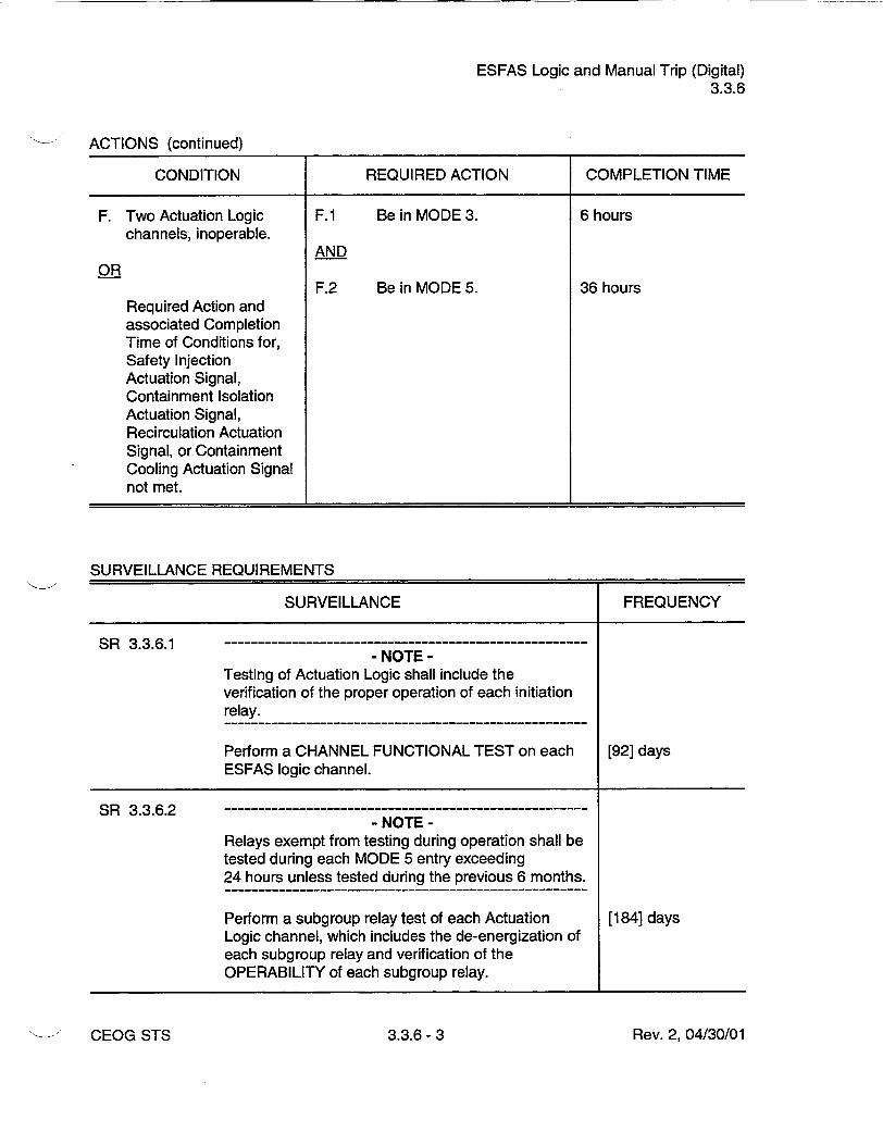
ESFAS Logic and Manual Trip (Digital) 3.3.6
ACTIONS (continued)
CONDITION REQUIRED ACTION COMPLETION TIME
F. Two Actuation Logic F.1 Be in MODE 3. 6 hours channels, inoperable.
AND OR
F.2 Be in MODE 5. 36 hours Required Action and associated Completion Time of Conditions for, Safety Injection Actuation Signal, Containment Isolation Actuation Signal, Recirculation Actuation Signal, or Containment Cooling Actuation Signal not met.
SURVEILLANCE REQUIREMENTS
SURVEILLANCE FREQUENCY
SR 3.3.6.1 - NOTE
Testing of Actuation Logic shall include the verification of the proper operation of each initiation relay.
Perform a CHANNEL FUNCTIONAL TEST on each [92] days ESFAS logic channel.
SR 3.3.6.2 - NOTE
Relays exempt from testing during operation shall be tested during each MODE 5 entry exceeding 24 hours unless tested during the previous 6 months.
Perform a subgroup relay test of each Actuation [184] days Logic channel, which includes the de-energization of each subgroup relay and verification of the OPERABILITY of each subgroup relay.
Rev. 2, 04/30/01CEOG STS 3.3.6- 3

ESFAS Logic and Manual Trip (Digital) 3.3.6
SURVEILLANCE REQUIREMENTS (continued)
SURVEILLANCE FREQUENCY
SR 3.3.6.3 Perform a CHANNEL FUNCTIONAL TEST on each [18] months ESFAS Manual Trip channel.
CEOG STS 3.3.6-4 Rev. 2, 04/30/01
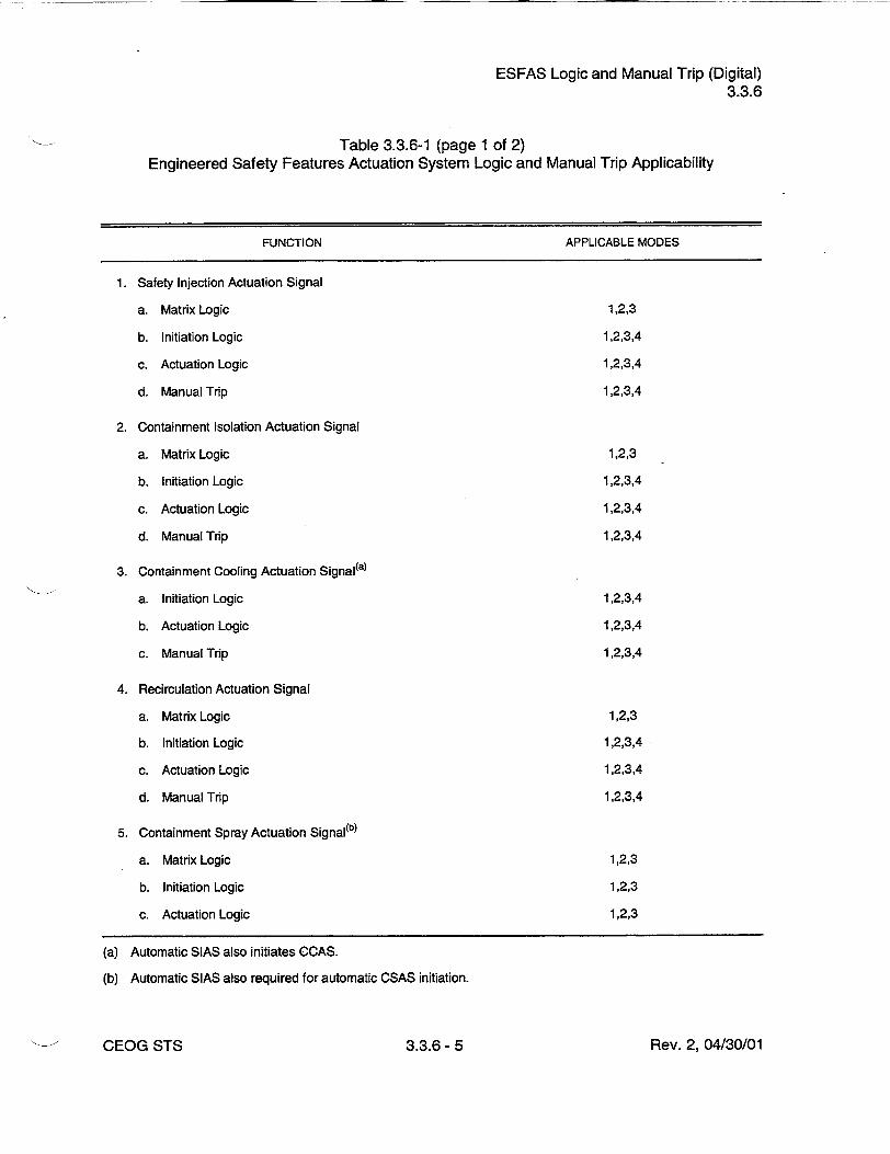
ESFAS Logic and Manual Trip (Digital) 3.3.6
Table 3.3.6-1 (page 1 of 2) Engineered Safety Features Actuation System Logic and Manual Trip Applicability
FUNCTION APPLICABLE MODES
1. Safety Injection Actuation Signal
a. Matrix Logic 1,2,3
b. Initiation Logic 1,2,3,4
c. Actuation Logic 1,2,3,4
d. Manual Trip 1,2,3,4
2. Containment Isolation Actuation Signal
a. Matrix Logic 1,2,3
b. Initiation Logic 1,2,3,4
c. Actuation Logic 1,2,3,4
d. Manual Trip 1,2,3,4
3. Containment Cooling Actuation Signal(a)
a. Initiation Logic 1,2,3,4
b. Actuation Logic 1,2,3,4
c. Manual Trip 1,2,3,4
4. Recirculation Actuation Signal
a. Matrix Logic 1,2,3
b. Initiation Logic 1,2,3,4
c. Actuation Logic 1,2,3,4
d. Manual Trip 1,2,3,4
5. Containment Spray Actuation Signal(b)
a. Matrix Logic 1,2,3
b. Initiation Logic 1,2,3
c. Actuation Logic 1,2,3
(a) Automatic SIAS also initiates CCAS.
(b) Automatic SIAS also required for automatic CSAS initiation.
Rev. 2, 04/30/01CEOG STS 3.3.6- 5

ESFAS Logic and Manual Trip (Digital) 3.3.6
Table 3.3.6-1 (page 2 of 2) Engineered Safety Features Actuation System Logic and Manual Trip Applicability
FUNCTION APPLICABLE MODES
5. Containment Spray Actuation Signal(b)
d. Manual Trip 1,2,3
6. Main Steam Isolation Signal
a. Matrix Logic 1,2,3
b. Initiation Logic 1,2,3
c. Actuation Logic 1,2,3
d. Manual Trip 1,2,3
7. Emergency Feedwater Actuation Signal SG #1 (EFAS-1)
a. Matrix Logic 1,2,3
b. Initiation Logic 1,2,3
c. Actuation Logic 1,2,3
d. Manual Trip 1,2,3
8. Emergency Feedwater Actuation Signal SG #2 (EFAS-2)
a. Matrix Logic 1,2,3
b. Initiation Logic 1,2,3
c. Actuation Logic 1,2,3
d. Manual Trip 1,2,3
(b) Automatic SIAS also required for automatic CSAS initiation.
CEOG STS Rev. 2, 04/30/013.3.6- 6

DG - LOVS (Digital) 3.3.7
3.3 INSTRUMENTATION
3.3.7 Diesel Generator (DG) - Loss of Voltage Start (LOVS) (Digital)
LCO 3.3.7
APPLICABILITY:
[Four] channels of Loss of Voltage Function and [four] channels of Degraded Voltage Function auto-initiation instrumentation per DG shall be OPERABLE.
MODES 1, 2, 3, and 4, When associated DG is required to be OPERABLE by LCO 3.8.2,
"AC Sources - Shutdown."
ACTIONS
- NOTE Separate Condition entry is allowed for each Function.
CONDITION REQUIRED ACTION COMPLETION TIME
A. One or more Functions A.1 Place channel in bypass or 1 hour with one channel per DG trip. inoperable.
AND
A.2 Restore channel to Prior to entering OPERABLE status. MODE 2 following
next MODE 5 entry
B. One or more Functions B.1 Enter applicable 1 hour with two channels per Conditions and Required DG inoperable. Actions for the associated
DG made inoperable by DG - LOVS instrumentation.
OR
Rev. 2, 04/30/01•- CEOG STS 3.3.7- 1

DG - LOVS (Digital) 3.3.7
ACTIONS (continued)
CONDITION REQUIRED ACTION COMPLETION TIME
B.2 - NOTE
LCO 3.0.4 is not applicable.
Place one channel in 1 hour bypass and the other channel in trip.
C. One or more Functions C. 1 Restore all but two 1 hour with more than two channels to OPERABLE channels inoperable, status.
D. Required Action and D.1 Enter applicable Immediately associated Completion Conditions and Required Time not met. Actions for the associated
DG made inoperable by DG - LOVS instrumentation.
SURVEILLANCE REQUIREMENTS
SUi RVEILLANCE FREQUENCY
SR 3.3.7.1 [Perform CHANNEL CHECK. 12 hours]
SR 3.3.7.2 Perform CHANNEL FUNCTIONAL TEST. [92] days
CEOG STS Rev. 2, 04/30/013.3.7-2
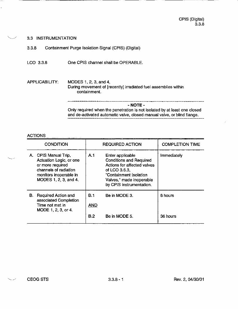
CPIS (Digital) 3.3.8
3.3 INSTRUMENTATION
3.3.8 Containment Purge Isolation Signal (CPIS) (Digital)
LCO 3.3.8
APPLICABILITY:
One CPIS channel shall be OPERABLE.
MODES 1, 2, 3, and 4, During movement of [recently] irradiated fuel assemblies within
containment.
- NOTE Only required when the penetration is not isolated by at least one closed and de-activated automatic valve, closed manual valve, or blind flange.
ACTIONS
CONDITION REQUIRED ACTION COMPLETION TIME
A. CPIS Manual Trip, A.1 Enter applicable Immediately Actuation Logic, or one Conditions and Required or more required Actions for affected valves channels of radiation of LCO 3.6.3, monitors inoperable in "Containment Isolation MODES 1, 2, 3, and 4. Valves," made inoperable
by CPIS instrumentation.
B. Required Action and B.1 Be in MODE 3. 6 hours associated Completion Time not met in AND MODE 1, 2, 3, or 4.
B.2 Be in MODE 5. 36 hours
Rev. 2, 04/30/01CEOG STS 3.3.8- 1
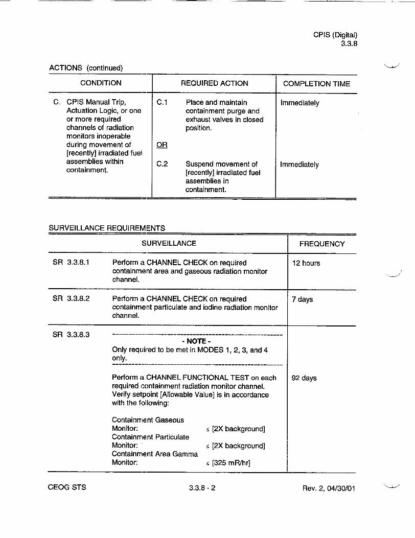
CPIS (Digital) 3.3.8
ACTIONS (continued)
CONDITION REQUIRED ACTION COMPLETION TIME
C. CPIS Manual Trip, C.1 Place and maintain Immediately Actuation Logic, or one containment purge and or more required exhaust valves in closed channels of radiation position. monitors inoperable during movement of OR [recently] irradiated fuel assemblies within C.2 Suspend movement of Immediately containment. [recently] irradiated fuel
assemblies in containment.
SURVEILLANCE REQUIREMENTS
SURVEILLANCE FREQUENCY
SR 3.3.8.1 Perform a CHANNEL CHECK on required 12 hours containment area and gaseous radiation monitor channel.
SR 3.3.8.2 Perform a CHANNEL CHECK on required 7 days containment particulate and iodine radiation monitor channel.
SR 3.3.8.3 -NOTE
Only required to be met in MODES 1, 2, 3, and 4 only.
Perform a CHANNEL FUNCTIONAL TEST on each 92 days required containment radiation monitor channel. Verify setpoint [Allowable Value] is in accordance with the following:
Containment Gaseous Monitor: • [2X background] Containment Particulate Monitor: • [2X background] Containment Area Gamma Monitor: • [325 mR/hr]
Rev. 2, 04/30/01CEOG STS 3.3.8-2

CPIS (Digital) 3.3.8
SURVEILLANCE REQUIREMENTS (continued)
SURVEILLANCE
- NOTE Only required to be met during CORE ALTERATIONS or during movement of irradiated fuel assemblies within containment.
Perform a CHANNEL FUNCTIONAL TEST on required containment radiation monitor channel. Verify setpoint [Allowable Value] is in accordance with the following:
Containment Gaseous Monitor: Containment Particulate Monitor: Containment Iodine Monitor: Containment Area Gamma Monitor:
•[2X background]
_ [2X background]
_ [2X background]
_ [2X background]
FREQUENCY
92 days
SR 3.3.8.5 - NOTE
Surveillance of Actuation Logic shall include the actuation of each initiation relay and verification of the proper operation of each initiation relay.
Perform a CHANNEL FUNCTIONAL TEST on [18] months required CPIS Actuation Logic channel.
SR 3.3.8.6 Perform a CHANNEL CALIBRATION on required [18] months containment radiation monitor channel.
SR 3.3.8.7 Verify that response time of required CPIS channel is [18] months within limits.
SR 3.3.8.8 Perform CHANNEL FUNCTIONAL TEST on required [18] months CPIS Manual Trip channel.
Rev. 2, 04/30/01
SR 3.3.8.4
CEOG STS 3.3.8- 3

CRIS (Digital) 3.3.9
3.3 INSTRUMENTATION
3.3.9 Control Room Isolation Signal (CRIS) (Digital)
LCO 3.3.9
APPLICABILITY:
One CRIS channel shall be OPERABLE.
MODES 1, 2, 3, 4, [5, and 6], During movement of [recently] irradiated fuel assemblies.
ACTIONS
CONDITION REQUIRED ACTION COMPLETION TIME
A. CRIS Manual Trip, A.1 Actuation Logic, or [one - NOTE
or more required Place Control Room channels of particulate/ Emergency Air Cleanup
iodine or gaseous] System (CREACS) in toxic radiation monitors gas protection mode if inoperable in MODE 1, automatic transfer to toxic 2, 3, or 4. gas protection mode
inoperable.
Place one CREACS train 1 hour in emergency radiation protection mode.
B. Required Action and B.1 Be in MODE 3. 6 hours associated Completion Time of Condition A not AND met.
B.2 Be in MODE 5. 36 hours
Rev. 2, 04/30/01CEOG STS 3.3.9 -1

CRIS (Digital) 3.3.9
ACTIONS (continued)
CONDITION REQUIRED ACTION COMPLETION TIME
C. CRIS Manual Trip, C.1 Actuation Logic, or - NOTE required particulate/ Place CREACS in toxic iodine or gaseous gas protection mode if radiation monitors automatic transfer to toxic inoperable [in MODE 5 gas protection mode or 6], or during inoperable. movement of [recently] irradiated fuel Place one CREACS train Immediately assemblies, in emergency radiation
protection mode.
OR
C.2.1 Suspend movement of Immediately [recently] irradiated fuel assemblies.
AND
- NOTE Limited plant cooldown or boron dilution is allowed provided the change is accounted for in the calculated SDM.
C.2.2 Suspend positive reactivity Immediately additions.
SURVEILLANCE REQUIREMENTS
S1JRVEILLANCE FREQUENCY
SR 3.3.9.1 Perform a CHANNEL CHECK on the required control 12 hours room radiation monitor channel.
Rev. 2, 04/30/01CEOG STS 3.3.9- 2
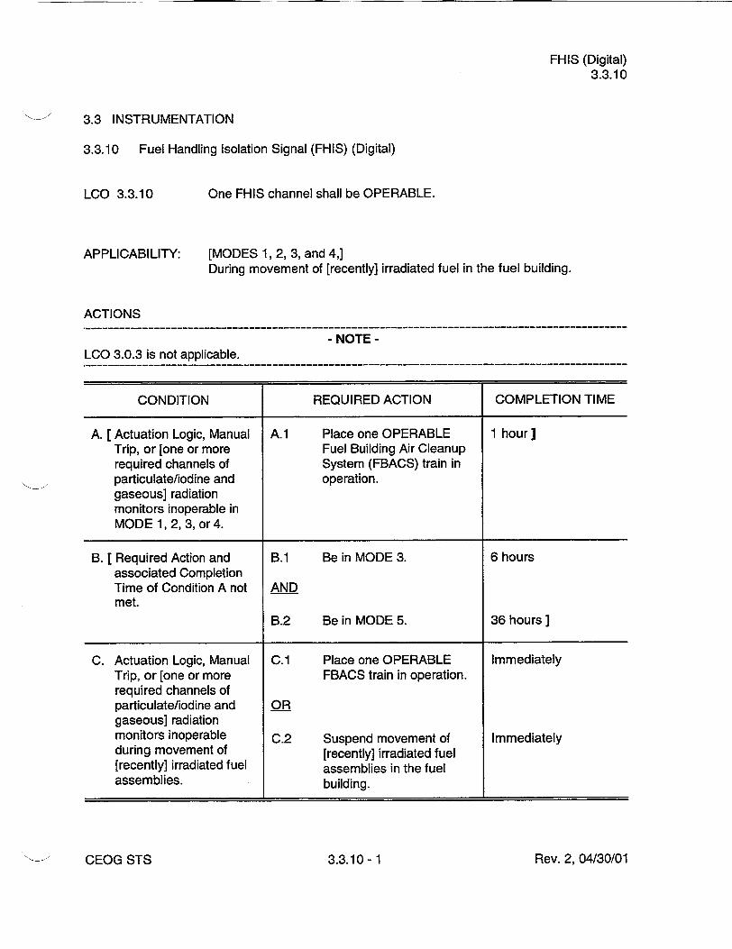
FHIS (Digital) 3.3.10
3.3 INSTRUMENTATION
3.3.10 Fuel Handling Isolation Signal (FHIS) (Digital)
LCO 3.3.10
APPLICABILITY:
One FHIS channel shall be OPERABLE.
[MODES 1, 2, 3, and 4,] During movement of [recently] irradiated fuel in the fuel building.
ACTIONS
- NOTE LCO 3.0.3 is not applicable.
CONDITION REQUIRED ACTION COMPLETION TIME
A. [Actuation Logic, Manual A.1 Place one OPERABLE 1 hour] Trip, or [one or more Fuel Building Air Cleanup required channels of System (FBACS) train in particulate/iodine and operation. gaseous] radiation monitors inoperable in MODE 1, 2, 3, or 4.
B. [Required Action and B.1 Be in MODE 3. 6 hours associated Completion Time of Condition A not AND met.
B.2 Be in MODE 5. 36 hours ]
C. Actuation Logic, Manual C.1 Place one OPERABLE Immediately Trip, or [one or more FBACS train in operation. required channels of particulate/iodine and OR gaseous] radiation monitors inoperable C.2 Suspend movement of Immediately during movement of [recently] irradiated fuel [recently] irradiated fuel assemblies in the fuel assemblies, building.
Rev. 2, 04/30/01CEOG STS 3.3.10- 1

FHIS (Digital) 3.3.10
SURVEILLANCE REQUIREMENTS
SURVEILLANCE FREQUENCY
SR 3.3.10.1 Perform a ,CHANNEL CHECK on required FHIS 12 hours radiation monitor channel.
SR 3.3.10.2 Perform a CHANNEL FUNCTIONAL TEST on 92 days required FHIS radiation monitor channel. Verify radiation monitor setpoint [Allowable Values]:
[Airborne Particulate/ Iodine: :5 [6E4] cpm above background]
Airborne Gaseous: _ [6E4] cpm above background
SR 3.3.10.3 -NOTE
Testing of Actuation Logic shall include the actuation of each initiation relay and verification of the proper operation cf each ignition relay. ----------------------- -----------Perform a CHANNEL FUNCTIONAL TEST on [18] months required FHIS Actuation Logic channel.
SR 3.3.10.4 Perform a CHANNEL FUNCTIONAL TEST on [18] months required FHIS Manual Trip logic.
SR 3.3.10.5 Perform a CHANNEL CALIBRATION on required [18] months FHIS radialion monitor channel.
SR 3.3.10.6 [ Verify response time of required FHIS channel is [18] months] within limits.
Rev. 2, 04/30/01CEOG STS 3.3.10- 2

PAM Instrumentation (Digital) 3.3.11
3.3 INSTRUMENTATION
3.3.11 Post Accident Monitoring (PAM) Instrumentation (Digital)
LCO 3.3.11
APPLICABILITY:
The PAM instrumentation for each Function in Table 3.3.11-1 shall be OPERABLE.
MODES 1, 2, and 3. During movement of [recently] irradiated fuel assemblies.
ACTIONS
- NOTES 1. LCO 3.0.4 not applicable.
2. Separate Condition entry is allowed for each Function.
CONDITION REQUIRED ACTION COMPLETION TIME
A. One or more Functions A.1 Restore required channel 30 days with one required to OPERABLE status. channel inoperable.
B. Required Action and B.1 Initiate action in Immediately associated Completion accordance with Time of Condition A not Specification 5.6.7. met.
C. - -------------- C.1 Restore one channel to 7 days - NOTE - OPERABLE status.
Not applicable to hydrogen monitor channels.
One or more Functions with two required channels inoperable.
D. Two hydrogen monitor D.1 Restore one hydrogen 72 hours channels inoperable, monitor channel to
OPERABLE status.
Rev. 2, 04/30/01CEOG STS 3.3.11 -1

PAM Instrumentation (Digital) 3.3.11
ACTIONS (continued)
CONDITION REQUIRED ACTION COMPLETION TIME
E. Required Action and E.1 Enter the Condition Immediately associated Completion referenced in Time of Condition C or D Table 3.3.11-1 for the not met. channel.
F. As required by Required F.1 Be in MODE 3. 6 hours Action E.1 and referenced in AND Table 3.3.11-1.
F.2 Be in MODE 4. 12 hours
G. [ As required by Required G.1 Initiate action in Immediately] Action E.1 and accordance with referenced in Specification 5.6.7. Table 3.3.11-1.
SURVEILLANCE REQUIREMENTS
- NOTE These SRs apply to each PAM instrumentation Function in Table 3.3.11-1.
SURVEILLANCE FREQUENCY
SR 3.3.11.1 Perform CHANNEL CHECK for each required 31 days instrumentation channel that is normally energized.
SR 3.3.11.2- ------------------------------ NOTE
Neutron detectors are excluded from the CHANNEL CALIBRATION. -----------------------------------------
Perform CHANNEL CALIBRATION. [18] months
Rev. 2, 04/30/01CEOG STS 3.3.11 -2
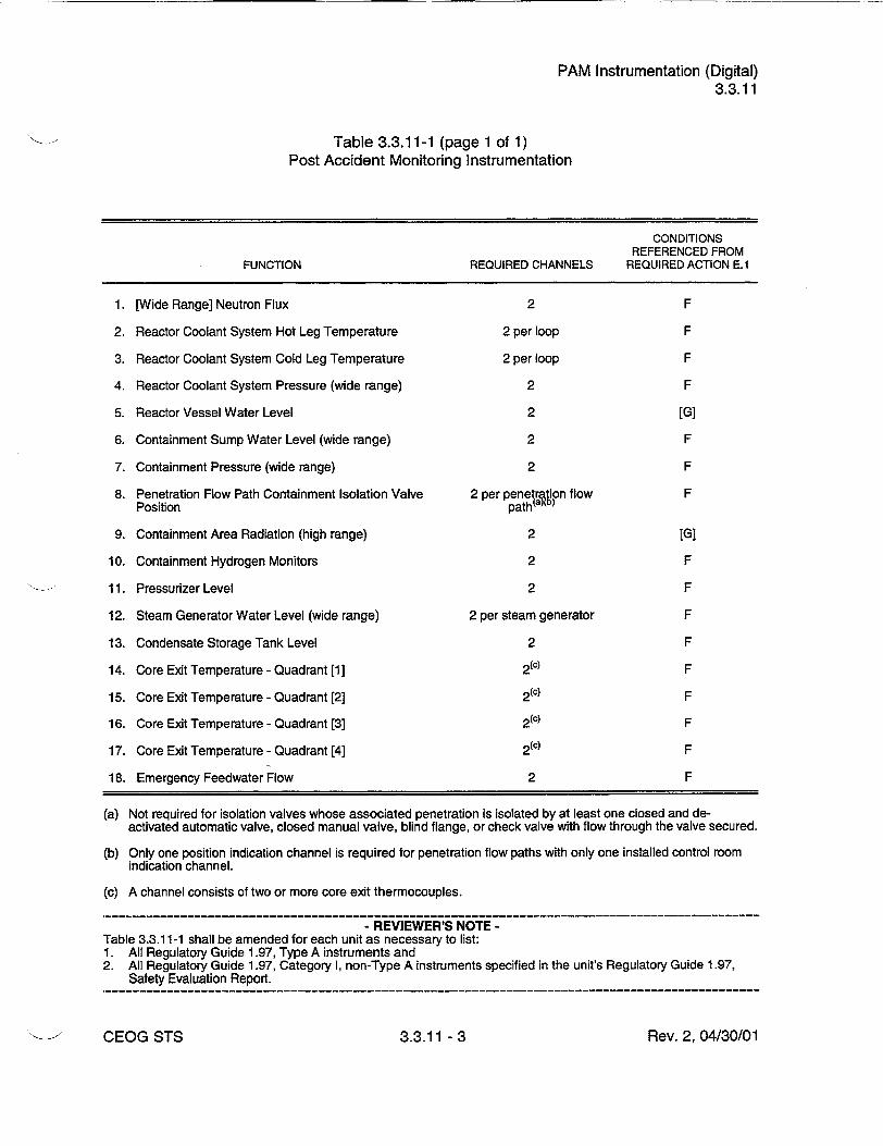
PAM Instrumentation (Digital) 3.3.11
Table 3.3.11-1 (page 1 of 1) Post Accident Monitoring Instrumentation
CONDITIONS REFERENCED FROM
FUNCTION REQUIRED CHANNELS REQUIRED ACTION E.1
1. [Wide Range] Neutron Flux 2 F
2. Reactor Coolant System Hot Leg Temperature 2 per loop F
3. Reactor Coolant System Cold Leg Temperature 2 per loop F
4. Reactor Coolant System Pressure (wide range) 2 F
5. Reactor Vessel Water Level 2 [G]
6. Containment Sump Water Level (wide range) 2 F
7. Containment Pressure (wide range) 2 F
8. Penetration Flow Path Containment Isolation Valve 2 per penetration flow F Position path(aJ J
9. Containment Area Radiation (high range) 2 [G]
10. Containment Hydrogen Monitors 2 F
11. Pressurizer Level 2 F
12. Steam Generator Water Level (wide range) 2 per steam generator F
13. Condensate Storage Tank Level 2 F
14. Core Exit Temperature - Quadrant [1] 2(c) F
15. Core Exit Temperature - Quadrant [2] 2 (c) F
16. Core Exit Temperature - Quadrant [3] 2 (c) F
17. Core Exit Temperature - Quadrant [4] 2 (c) F
18. Emergency Feedwater Flow 2 F
(a) Not required for isolation valves whose associated penetration is isolated by at least one closed and deactivated automatic valve, closed manual valve, blind flange, or check valve with flow through the valve secured.
(b) Only one position indication channel is required for penetration flow paths with only one installed control room indication channel.
(c) A channel consists of two or more core exit thermocouples.
- REVIEWER'S NOTE Table 3.3.11-1 shall be amended for each unit as necessary to list: 1. All Regulatory Guide 1.97, Type A instruments and 2. All Regulatory Guide 1.97, Category I, non-Type A instruments specified in the unit's Regulatory Guide 1.97,
Safety Evaluation Report.
Rev. 2, 04/30/01CEOG STS 3.3.11 - 3

Remote Shutdown System (Digital) 3.3.12
3.3 INSTRUMENTATION
3.3.12 Remote Shutdown System (Digital)
LCO 3.3.12
APPLICABILITY:
The Remote Shutdown System Functions shall be OPERABLE.
MODES 1, 2, and 3.
- NOTES 1. LCO 3.0.4 is not applicable.
2. Separate Condition entry is allowed for each Function.
ACTIONS
CONDITION REQUIRED ACTION COMPLETION TIME
A. One or more required A.1 Restore required 30 days Functions inoperable. Functions to OPERABLE
status.
B. Required Action and B.1 Be in MODE 3. 6 hours associated Completion Time not met. AND
B.2 Be in MODE 4. [12] hours
SURVEILLANCE REQUIREMENTS
SURVEILLANCE FREQUENCY
SR 3.3.12.1 [Perform CHANNEL CHECK for each required 31 days] instrumentation channel that is normally energized.
SR 3.3.12.2 Verify each required control circuit and transfer [18] months switch is capable of performing the intended function.
Rev. 2, 04/30/01CEOG STS 3.3.12- 1
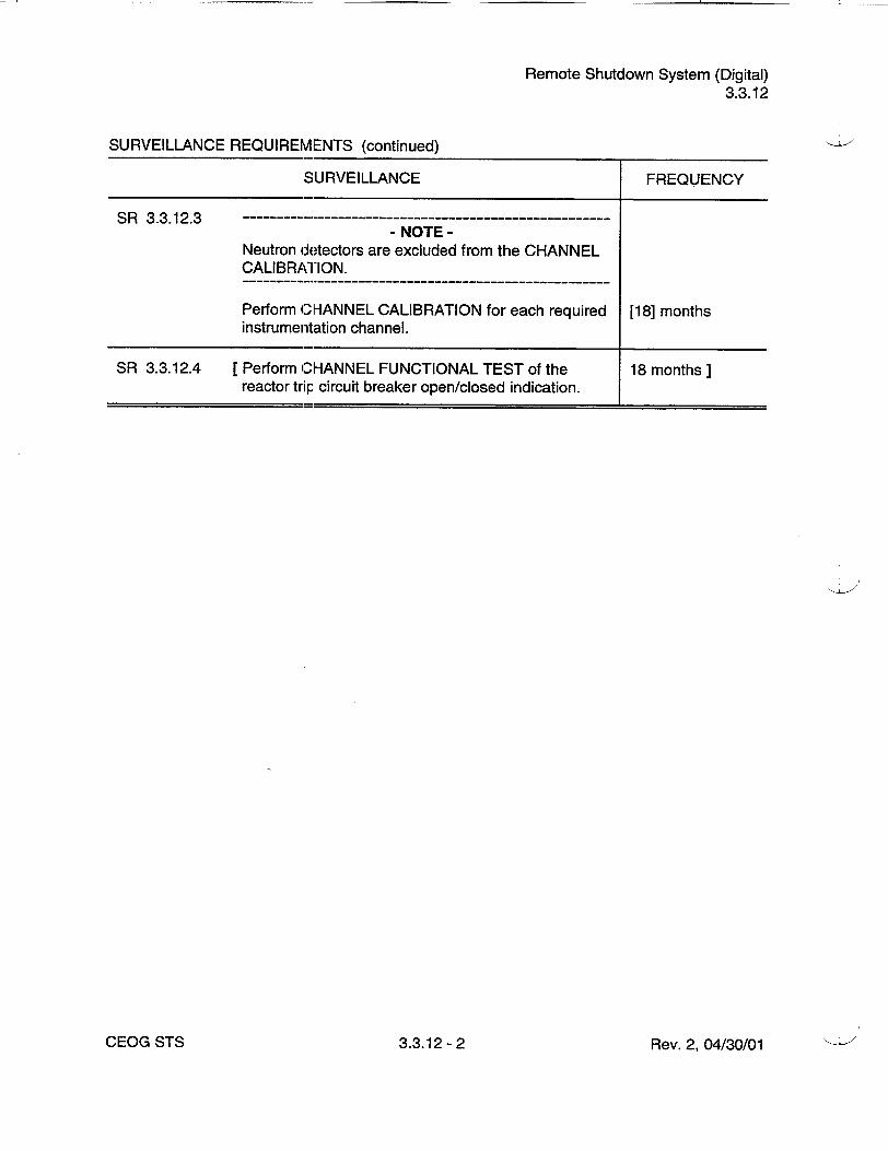
Remote Shutdown System (Digital) 3.3.12
SURVEILLANCE REQUIREMENTS (continued)
SURVEILLANCE FREQUENCY
SR 3.3.12.3 - NOTE
Neutron detectors are excluded from the CHANNEL CALIBRATION.
Perform CHANNEL CALIBRATION for each required [18] months instrumentation channel.
SR 3.3.12.4 [Perform CHANNEL FUNCTIONAL TEST of the 18 months] reactor trip, circuit breaker open/closed indication.
Rev. 2, 04/30/01CEOG STS 3.3.12 -2

[Logarithmic] Power Monitoring Channels (Digital) 3.3.13
3.3 INSTRUMENTATION
3.3.13 [Logarithmic] Power Monitoring Channels (Digital)
LCO 3.3.13
APPLICABILITY:
Two channels of [logarithmic] power level monitoring instrumentation shall be OPERABLE.
MODES 3, 4, and 5, with the reactor trip circuit breakers open or Control Element Assembly (CEA) Drive System not capable of CEA withdrawal.
ACTIONS
CONDITION REQUIRED ACTION COMPLETION TIME
A. One or more required -- NOTE- channels inoperable. - NOTE
Limited plant cooldown or boron dilution is allowed provided the change is accounted for in the calculated SDM.
A. 1 Suspend all operations Immediately involving positive reactivity additions.
AND
A.2 Perform SDM verification 4 hours in accordance with SR 3.1.1.1, if Tavg > AND 200 0F.
Once per 12 hours thereafter
Rev. 2, 04/30/01CEOG STS 3.3.13- 1

[Logarithmic] Power Monitoring Channels (Digital) 3.3.13
SURVEILLANCE REQUIREMENTS
,SURVEILLANCE FREQUENCY
SR 3.3.13.1 Perform CHANNEL CHECK. 12 hours
SR 3.3.13.2 Perform CHANNEL FUNCTIONAL TEST. [92] days
SR 3.3.13.3 --------------.---------------------------------------- NOTE
Neutron detectors are excluded from CHANNEL CALIBRATION.
Perform CHANNEL CALIBRATION. [18] months
Rev. 2, 04/30/01CEOG STS 3.3.13 -2

RCS Pressure, Temperature, and Flow [DNB] Limits 3.4.1
3.4 REACTOR COOLANT SYSTEM (RCS)
3.4.1 RCS Pressure, Temperature, and Flow [Departure from Nucleate Boiling (DNB)] Limits
LCO 3.4.1
APPLICABILITY:
RCS DNB parameters for pressurizer pressure, cold leg temperature, and RCS total flow rate shall be within the limits specified below:
a. Pressurizer pressure > [2025] psia and _< [2275] psia,
b. RCS cold leg temperature (Tc):
1. Ž [535]0F and _ [558]°F for < [70]% RTP or
2. Ž [544]°F and _g [588]0 F for , [70]% RTP, and
c. RCS total flow rate Ž [148 E6] lb/hour.
MODE 1.
- NOTE
Pressurizer pressure limit does not apply during:
a. THERMAL POWER ramp > 5% RTP per minute or
b. THERMAL POWER step> 10% RTP.
ACTIONS
CONDITION REQUIRED ACTION COMPLETION TIME
A. Pressurizer pressure or A.1 Restore parameter(s) to 2 hours RCS flow rate not within within limit. limits.
B. Required Action and B.1 Be in MODE 2. 6 hours associated Completion Time of Condition A not met.
Rev. 2, 04/30/01CEOG STS 3.4.1- 1

RCS Pressure, Temperature, and Flow [DNB] Limits 3.4.1
ACTIONS (continued)
CONDITION REQUIRED ACTION COMPLETION TIME
C. RCS cold leg C.1 Restore cold leg 2 hours temperature not within temperature to within limits, limits.
D. Required Action and D.1 Reduce THERMAL 6 hours associated Completion POWER to • [30]% RTP. Time of Condition-C not met.
SURVEILLANCE REQUIREMENTS
SURVEILLANCE FREQUENCY
SR 3.4.1.1 Verify pressurizer pressure Ž [2025] psia and 12 hours
! [2275] psia.
SR 3.4.1.2 Verify RCS cold leg temperature: 12 hours
1. a [535]°F and _• [558]°F for < [70]% RTP or
2. > [544]0 F and :g [558]°F for > [70]% RTP.
SR 3.4.1.3 -------------NOTE
Only required to be met in MODE 1.
Verify RCS total flow rate Ž [148 E6] lb/hour. 12 hours
SR 3.4.1.4- ---------------- ----------NOTE
Not required to be performed until [24] hours after > [90]% RTP.
Verify by precision heat balance that RCS total flow [18] months rate within limits specified in the COLR.
CEOG STS 3.4.1- 2 Rev. 2, 04/30/01
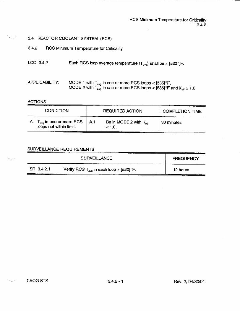
RCS Minimum Temperature for Criticality 3.4.2
3.4 REACTOR COOLANT SYSTEM (RCS)
3.4.2 RCS Minimum Temperature for Criticality
LCO 3.4.2
APPLICABILITY:
Each RCS loop average temperature (Tavg) shall be > [5200 ]F.
MODE 1 with Tavg in one or more RCS loops < [535]OF, MODE 2 with Tavg in one or more RCS loops < [535]°F and Keff Ž 1.0.
ACTIONS
CONDITION REQUIRED ACTION COMPLETION TIME
A. Tag in one or more RCS A.1 Be in MODE 2 with Keff 30 minutes loops not within limit. < 1.0.
SURVEILLANCE REQUIREMENTS
SURVEILLANCE FREQUENCY
SR 3.4.2.1 Verify RCS T,,,g in each loop ýý [520]°F. 12 hours
Rev. 2, 04/30/01CEOG STS 3.4.2- 1

RCS P/T Limits 3.4.3
3.4 REACTOR COOLANT SYSTEM (RCS)
3.4.3 RCS Pressure and Temperature (P/T) Limits
LCO 3.4.3
APPLICABILITY:
RCS pressure, RCS temperature, and RCS heatup and cooldown rates shall be maintained within the limits specified in the PTLR.
At all times.
ACTIONS
CONDITION REQUIRED ACTION COMPLETION TIME
A. -------------------- A.1 Restore parameter(s) to 30 minutes - NOTE - within limits.
Required Action A.2 shall be completed AND whenever this Condition is entered.
------------ A.2 Determine RCS is 72 hours
Requirements of acceptable for continued
LCO not met in MODE 1, operation.
2, 3, or4.
B. Required Action and B.1 Be in MODE 3. 6 hours associated Completion Time of Condition A not AND met.
B.2 Be in MODE 5 with 36 hours RCS pressure < [500] psig.
C. ------- --------- C.1 Initiate action to restore Immediately - NOTE - parameter(s) to within
Required Action C.2 limits. shall be completed whenever this Condition AND is entered.
Requirements of LCO not met any time in other than MODE 1, 2, 3, or 4.
Rev. 2, 04/30/01CEOG STS 3.4.3- 1

RCS P/T Limits 3.4.3
ACTIONS (continued)
CONDITION REQUIRED ACTION COMPLETION TIME
C.2 Determine RCS is Prior to entering acceptable for continued MODE 4 operation.
SURVEILLANCE REQUIREMENTS
SURVEILLANCE FREQUENCY
SR 3.4.3.1 -NOTE
Only required to be performed during RCS heatup and cooldown operations and RCS inservice leak and hydrostatic testing.
Verify RCS pressure, RCS temperature, and RCS 30 minutes heatup arid cooldown rates within limits specified in the PTLR.
Rev. 2, 04/30/01CEOG STS 3.4.3- 2

RCS Loops - MODES 1 and 2 3.4.4
3.4 REACTOR COOLANT SYSTEM (RCS)
3.4.4 RCS Loops - MODES 1 and 2
LCO 3.4.4
APPLICABILITY:
Two RCS loops shall be OPERABLE and in operation.
MODES 1 and 2.
ACTIONS
CONDITION REQUIRED ACTION COMPLETION TIME
A. Requirements of A.1 Be in MODE 3. 6 hours LCO not met.
SURVEILLANCE REQUIREMENTS
SURVEILLANCE FREQUENCY
SR 3.4.4.1 Verify each RCS loop is in operation. 12 hours
Rev. 2, 04/30/01CEOG STS 3.4.4- 1